EP2721871B1 - System and method for accessing a structure using directional antennas and a wireless token - Google Patents
System and method for accessing a structure using directional antennas and a wireless token Download PDFInfo
- Publication number
- EP2721871B1 EP2721871B1 EP12799757.5A EP12799757A EP2721871B1 EP 2721871 B1 EP2721871 B1 EP 2721871B1 EP 12799757 A EP12799757 A EP 12799757A EP 2721871 B1 EP2721871 B1 EP 2721871B1
- Authority
- EP
- European Patent Office
- Prior art keywords
- access
- user device
- wireless
- enclosed area
- wireless user
- Prior art date
- Legal status (The legal status is an assumption and is not a legal conclusion. Google has not performed a legal analysis and makes no representation as to the accuracy of the status listed.)
- Active
Links
Images
Classifications
-
- H—ELECTRICITY
- H04—ELECTRIC COMMUNICATION TECHNIQUE
- H04L—TRANSMISSION OF DIGITAL INFORMATION, e.g. TELEGRAPHIC COMMUNICATION
- H04L63/00—Network architectures or network communication protocols for network security
- H04L63/08—Network architectures or network communication protocols for network security for authentication of entities
- H04L63/0853—Network architectures or network communication protocols for network security for authentication of entities using an additional device, e.g. smartcard, SIM or a different communication terminal
-
- G—PHYSICS
- G07—CHECKING-DEVICES
- G07C—TIME OR ATTENDANCE REGISTERS; REGISTERING OR INDICATING THE WORKING OF MACHINES; GENERATING RANDOM NUMBERS; VOTING OR LOTTERY APPARATUS; ARRANGEMENTS, SYSTEMS OR APPARATUS FOR CHECKING NOT PROVIDED FOR ELSEWHERE
- G07C9/00—Individual registration on entry or exit
- G07C9/00174—Electronically operated locks; Circuits therefor; Nonmechanical keys therefor, e.g. passive or active electrical keys or other data carriers without mechanical keys
- G07C9/00309—Electronically operated locks; Circuits therefor; Nonmechanical keys therefor, e.g. passive or active electrical keys or other data carriers without mechanical keys operated with bidirectional data transmission between data carrier and locks
-
- H—ELECTRICITY
- H04—ELECTRIC COMMUNICATION TECHNIQUE
- H04L—TRANSMISSION OF DIGITAL INFORMATION, e.g. TELEGRAPHIC COMMUNICATION
- H04L63/00—Network architectures or network communication protocols for network security
- H04L63/10—Network architectures or network communication protocols for network security for controlling access to devices or network resources
- H04L63/107—Network architectures or network communication protocols for network security for controlling access to devices or network resources wherein the security policies are location-dependent, e.g. entities privileges depend on current location or allowing specific operations only from locally connected terminals
-
- H—ELECTRICITY
- H04—ELECTRIC COMMUNICATION TECHNIQUE
- H04W—WIRELESS COMMUNICATION NETWORKS
- H04W12/00—Security arrangements; Authentication; Protecting privacy or anonymity
- H04W12/08—Access security
- H04W12/084—Access security using delegated authorisation, e.g. open authorisation [OAuth] protocol
-
- H—ELECTRICITY
- H04—ELECTRIC COMMUNICATION TECHNIQUE
- H04W—WIRELESS COMMUNICATION NETWORKS
- H04W12/00—Security arrangements; Authentication; Protecting privacy or anonymity
- H04W12/08—Access security
- H04W12/088—Access security using filters or firewalls
-
- H—ELECTRICITY
- H04—ELECTRIC COMMUNICATION TECHNIQUE
- H04W—WIRELESS COMMUNICATION NETWORKS
- H04W4/00—Services specially adapted for wireless communication networks; Facilities therefor
- H04W4/30—Services specially adapted for particular environments, situations or purposes
- H04W4/33—Services specially adapted for particular environments, situations or purposes for indoor environments, e.g. buildings
-
- H—ELECTRICITY
- H04—ELECTRIC COMMUNICATION TECHNIQUE
- H04W—WIRELESS COMMUNICATION NETWORKS
- H04W4/00—Services specially adapted for wireless communication networks; Facilities therefor
- H04W4/80—Services using short range communication, e.g. near-field communication [NFC], radio-frequency identification [RFID] or low energy communication
-
- H—ELECTRICITY
- H04—ELECTRIC COMMUNICATION TECHNIQUE
- H04W—WIRELESS COMMUNICATION NETWORKS
- H04W48/00—Access restriction; Network selection; Access point selection
- H04W48/02—Access restriction performed under specific conditions
- H04W48/04—Access restriction performed under specific conditions based on user or terminal location or mobility data, e.g. moving direction, speed
Definitions
- the present invention generally relates to an access system including a wireless token and a proximity and location verification device. More particularly, the present invention pertains to a three point access system which includes a wireless token which transmits a request for access which ultimately results in a door being unlocked.
- an access system 20 advantageously permits a user to access a structure 40 using a wireless token 24.
- similar embodiments of the access system to be described also encompass systems for controlling access to other structures or openings/doors thereof.
- the access system 20 is particularly well suited to providing access to structures in which the authorized users are frequently changes, such as a hotel. As such, in the illustrated embodiment, according to FIG.
- the described system comprises an access system 20 for allowing a hotel guest to access their assigned hotel room 40 using a wireless token 24, which in the preferred form, is an electronic device capable of short range wireless communication, such as a device implementing Bluetooth®, Zigbee®, or some other low-power wireless communication protocol/standard.
- a wireless token 24 is an electronic device capable of short range wireless communication, such as a device implementing Bluetooth®, Zigbee®, or some other low-power wireless communication protocol/standard.
- Examples of other structures for which the novel access system may be adapted include other rooms within a hotel (i.e. workout rooms, pools, VIP lounges), office buildings, school/university buildings, laboratories, warehouses, and portions thereof, event ticket gates/turnstiles, movie theatres, safety deposit boxes, mailboxes, lockers, or other enclosures for which providing selective user access is desired.
- the access system 20 includes one or more wireless tokens 24 which allow a user to access their assigned hotel room without a traditional key or card.
- the access system 20 includes a data network 54.
- Data network 54 is preferably a private local area network (LAN) and may comprise the Internet, which is a TCP/IP based global network; however, the user of the term "Internet” herein shall be understood to refer to at least a portion of any public interconnected electronic network which interchanges data by packet-switching.
- Access system 20 additionally comprises a mechanical lock 34 for locking and unlocking a structure 40 (partially shown).
- a user gains access to the structure 40 via door 32.
- mechanical lock 34 is a mechanical door lock, which includes a locking mechanism similar to a common entry or exterior lock, but is further capable of self-unlocking in response to an electronic signal, in addition to other functionality described herein.
- mechanical lock 34 may include a cam lock, rotary latch, electro-mechanical lock, magnetic lock, or the like.
- lock 34 unlocks in response to an electrical signal sent from a wireless token 24 and/or access node 50.
- the electrical signal is sent wirelessly, such as over a low-power RF connection, such as a Zigbee® connection.
- the lock 34 returns to a locked state following the passage of a predetermined time period or a user opening and closing the door following the receipt of an unlock signal.
- lock 34 or door 40 may also include a mechanical key slot, key card, or other entry permitting authentication means 36 in addition to, or as backup for, that described herein with respect to lock 34.
- system 20 may be applied to access restrictions other than locks including, for example, an elevator control system providing limited access, a garage door, or others access barriers, as described later.
- Access system 20 also utilizes at least one access node 50 to interface with wireless token 24 and lock 34.
- Access node 50 is a wireless node implementing a common short-range wireless standard, such as Bluetooth® or ZigBee®, to those implemented by wireless token 24 and lock 34.
- Access node 50 is also connected to server 60 via firewall 52 and network 54.
- access system 20 includes a plurality of access nodes, such as access node 50, where each node is strategically positioned near a specified structure (i.e. a hotel room).
- the access nodes are preferably always in a active mode so that wireless tokens 24 may be connected with them on demand in the event the wireless token 24 is authorized, such as by having an authorized MAC address or some other selected security mechanism.
- the access nodes 50 are not in a discoverable mode and the pairing of the access nodes 50 with wireless token 24 occurs prior to the user's arrival programmatically.
- access node 50 is operatively connected to server 60 to process and authenticate electronic unlock requests from wireless tokens 24.
- Firewall 52 includes at least a hardware or software implemented firewall or other selected security features to prevent external access to server 60 or access node 50.
- the location information maintained by access node 50 is linked to the present/assigned location of the node and is used in processing any unlock request.
- an access node on the fourth floor of a hotel in downtown Chicago may be assigned a unique hotel identifier coupled with a hotel zone identifier.
- the node may be assigned a single identifier which is then linked to its location by the wireless token 24 or server 60.
- a mock floor plan is shown in FIG 3 .
- the mock floor plan illustrates a number of complete circles which denote the wireless range of a number of access nodes 50 for purposes of covering the entryway/hallway of a hotel floor and one or more doors.
- server 60 operates in conjunction with access node 50 over internal network 54 to authenticate any wireless token 24 which comes within its range.
- the access node 50 receives information from the wireless token 24 and seeks to identify one or more structures within its coverage area to which the wireless token 24 is authorized to enter.
- the server 60 serves to authenticate the request or a portion thereof using a reservations and occupancy database, while in other forms, the access node 50 may perform at least a portion of the authentication.
- server 60 processes each request corresponding to an authentication request received by access node 50 from wireless token 24, and upon proper authentication, confirms the authentication for one or more structures to access node 50 which then transmits an electronic signal to the corresponding lock(s), such as lock 34, notifying the lock to wake-up for a predetermined period of time in order to communication with nearby authorized wireless token 24.
- the access node 50 not only notifies lock 34 that it should wake-up, but also communicates information to lock 34 regarding which wireless token 24 it should be expecting.
- server 60 is described and illustrated as being a server, it should be understood that server 60 may be any computer, including a client server arrangement.
- Server 60 may interface with access node 50 by either a wireless or hardwired interconnection.
- the connection is a secured connection.
- a non-limiting example list of potential interfaces includes IR, optical, RF, serial port, IP network, and USB.
- the functions of server 60 and access node 50 may be integrated into one computer system.
- wireless token 24 connects to lock 34 and provides authorization information.
- the authorization information provided may be the same as the authorization information provided by wireless token 24 to access node 50, described above.
- the authorization information provided by wireless node 24 may be unlock information provided to wireless node 24 by access node 50 earlier in the process.
- lock 34 may communicate with access node 50 to confirm the authorization or wireless token 24. In the event the authorization information received by lock 34 is authorized, by whatever means selected, lock 34 determines that a legitimate unlock request is present.
- lock 34 assesses the location of wireless token 24 to determine whether it is within a designated area.
- lock 34 includes two directional antennas 38 and 39 which are operable to communicate with wireless token 24 over a low power wireless transmission protocol.
- FIG. 1 according to the illustrated form, lock 34 and antennas 38 and 39 are located within the mortise of door 32.
- antenna 38 faces outward from door 32 and structure 40 while antenna 39 faces inward from door 32 and into structure 40.
- RSSI received signal strength indication
- lock 34 can confirm that the requesting user device is within a designated area, such as an 2 foot semi-circular area on the outside of a door, based upon the signal strength received as well as the differential of the signal strength between the two opposite facing directional antennas. Such a confirmation ensures that access to a structure won't ever be improperly granted based upon a user device within the structure.
- a designated area such as an 2 foot semi-circular area on the outside of a door
- the mock floor plan shown in FIG. 3 illustrates a number of desired areas as small half circles outside of hotel room doors, which area the effective coverage areas for the required signal strength to be detected by antenna 38 with respect to wireless token 24. It is only when a wireless token 24 is within these areas that their respective doors may be opened if authorized.
- a number of larger half circles in the interior of the hotel rooms show the field of coverage of antennas 39 which are used to detect when wireless token is within the corresponding hotel room.
- lock 34 is operably coupled to an override switch (not shown) having an access disable state. Asserting the override switch prevents the access system 20 from permitting access to corresponding structure 40.
- the override switch may be asserted when a guest engages a deadbolt or bar latch within their hotel room.
- the override switch is incorporated into an electronic control, not shown here, accessible to the user within structure 40.
- FIG. 2 A flowchart illustrating one set of steps performed in configuring a wireless token 24 for use in accessing a structure 40 according to one embodiment of the present invention is shown in FIG. 2 .
- the process involves a wireless token 24 and the various other components of access system 20.
- the wireless token 24 may be a dedicated wireless token or another device, such as a mobile telephone, laptop, tablet, or other portable electronic device; however, it is understood that numerous other networked appliances are also intended.
- confirmation information stored by server 60 preferably identifies the hotel and the user and includes a check-in/check-out date along with details of the type of room requested/reserved.
- this confirmation information is received by server 60 as a result of a hotel booking being made for a user either online, in person, or over the phone.
- the wireless token 24 Upon checking into the hotel, or being authorized to access some other structure in other adaptations of the system 20, the wireless token 24 is automatically configured to pair with or otherwise connect to access nodes located near the structure 40. Additionally, the details of the assigned room or structure, including its number and location, are then stored by server 60 is association with wireless token 24. This ensures that access nodes 50 will proper identify the room wireless token 24 is assigned to access and be able to authenticate its request for access. It shall be appreciated that this process may be modified to accommodate more than one authorized hotel guest per room, such as having two wireless devices authorized to enter the same hotel room, or allowing a current guest to authorize the wireless device of another to access the hotel room for any portion of their remaining stay.
- FIG. 2 a flowchart illustrating one set of steps performed in allowing a user to access structure 40 using wireless token 24 and the various other components of access system 20 is shown. The following description is with continuing reference to access system 20 of FIG. 1
- the process begins at start point 200 with the user along with the wireless token 24 arriving in a location within range of an access node 50.
- a user device such as either a mobile telephone or wireless token 24, are detected by the access node 50 respectively.
- the access node determines whether or not the user is authorized to enter one of the structure entrances that is proximate to access node 50 (step 206). If the user is not authorized, the process ends at point 208. If the user is authorized, the user device connects to the access node 50 (step 210).
- the access node 50 compares its perceived signal strength from the nearest access nodes of the floor above and below (if available) to ensure that its signal is the strongest (step 212). If the user is determined to be on another floor, the process proceeds to and ends at step 214. Alternatively, if the access node 50 determines that the user is on its associated floor, the process proceeds to step 216. In step 216 the access node 50 collaborates with server 60 to confirm the credentials provided by the user device. In the event the credentials are not confirmed, the process ends at step 218.
- step 220 access node 50 sends a wake-up signal to the lock, such as lock 34, associated with the structure, such as structure 40, to which the user is authorized. Additionally, the access node 50 may detect the type of wireless standard the user device is capable of such that the proper wireless standard may be activated by the selected door lock 34 in step 220.
- the wake-up signal may also include an access code, such as a temporary alphanumeric code or the like, which must be matched by the user device in order to cause the lock to open.
- the second stage of the process beings in step 226 where the user device connects to the now active lock 34.
- the dual antennas 38 and 39 of lock 34 detect a RSSI from the user device (step 228).
- the central focus of the antennas 38 and 39 are directly opposite of one another.
- the central focus of the antennas 38 and 39 may only be offset by at least 130 degrees.
- the central focus may differ by 150 degrees or more. If the user device is determined to be inside of the structure, such as by having a stronger signal strength via the internally facing antenna 39, the process proceeds through steps 232, and 234, whereby it is determined that the user is already in the room and the process ends subject to starting over.
- the process proceeds to authenticate the request by comparing the security code provided by the user device to the stored access code received from node 50 (step 238) until lock 34 unlocks either provides the user with access to structure 40 (step 240) upon a successful authentication or the process ends at point 242.
- door lock 34 takes appropriate samples of RSSI relative to wireless token 24 on either side of door, using antennas 38 and 39.
- the samples may include several periodic RSSI readings which are then averaged or otherwise combine to reduce interference, noise, or the like from a single reading. Based upon these readings, lock 34 makes a determination of whether wireless token 24 is inside and outside of door 32. Additionally, the lock 34 may use the RSSI samples of antenna 38 to determine the distance wireless token 24 is from lock 34 for purposes of determining its presence within the defined proximity range outside of the door 32 as well. Once measurements averages are conducted, and presence of token/device and it is determined that he is in the proper unlock zone (range of outside proximity), the unlock of step 242 is granted.
- lock 34 may periodically transmit information to access node 50 for passing along to server 60 which indicates the user is still in the hotel room. This information may trigger the in-room temperature to be maintained, and upon detecting that the user is no longer in the room, the temperature may be raised to a user-specified or standard level or it may trigger the lights to be turned off, as described in U.S. Patent Application 10/126,486 to Sunyich entitled "Personalized Smart Room", which is hereby incorporated by reference to the extent not inconsistent.
Description
- The present invention generally relates to an access system including a wireless token and a proximity and location verification device. More particularly, the present invention pertains to a three point access system which includes a wireless token which transmits a request for access which ultimately results in a door being unlocked.
- Prior art systems exist for providing access to structures using wireless devices. For example,
U.S. Patent Publication 2010/201482 describes such a system. Traditionally, system such as this utilized wireless transmission ranges to establish a zone where the wireless device must be located in order to properly request and be granted access to the structure. However, such system does not provide for any detection of whether the wireless device seeking access is located inside or outside of the structure. To prevent the undesirable situation in which an authorized user, along with the wireless device, is within a structure, and an unlock request is transmitted to the access system, thereby permitting access to the structure, the present disclosure incorporates directional antennas within the system which operate to determine whether or not the wireless device requesting access is within the structure or properly outside of the structure. - The use of directional antennas and received signal strength indicators (RSSI) is not new, for example, see
US 2011/065391 . However, the unique application to a wireless access system such, such as that references above, to solve the technical problem of inside/outside detection for use in granting access to a structure within an access system has not previously been utilized. - The invention is defined in the independent claims. Particular embodiments are set out in the dependent claims.
-
-
FIG. 1 is a diagrammatic view of an access system according to one implementation of the present invention. -
FIG. 2 is a process flow diagram illustrating one set of steps performed in enabling a user to access a structure using the novel access system, including a wireless token. -
FIG. 3 is a mock floor plan illustrating the coverage areas of the access node and the two door lock antennas in a typical multi-room hotel setting. - Some of the embodiments described hereinafter are not embodiments of the invention according to the claims.
- For the purposes of promoting and understanding of the principles of the invention, reference will now be made to the embodiment illustrated in the drawings and specific language will be used to describe the same. It will nevertheless be understood that no limitation of the scope of the invention is thereby intended. Any alterations and further modifications in the described embodiments, and any further applications of the principles of the invention as described herein are contemplated as would normally occur to one skilled in the art to which the invention relates.
- Currently, systems exist, such as the Signature RFID/NFC system from VingCard, which provide a user access to a hotel room using their mobile phone. Alternatively, other point-to-point systems exist which provide access to an office, lab, or other secured area using a wireless token, such as an RFID tag or card. However, such systems are limited in that the token is limited to a single identifier which leaves open a crucial security flaw which would allow for duplication of the token's responsive signal. Additionally, given the wireless range of these tokens, an undesirable situation may arise in which the token is within range of the lock or RFID reader when inside of the secured area. This presents the possibility that access may be granted to anyone seeking entry at that time.
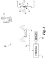
- As shown in
FIG. 1 , one embodiment of anaccess system 20 advantageously permits a user to access astructure 40 using awireless token 24. In addition to lodging and workplace access systems, it will be appreciated that similar embodiments of the access system to be described also encompass systems for controlling access to other structures or openings/doors thereof. In particular, theaccess system 20 is particularly well suited to providing access to structures in which the authorized users are frequently changes, such as a hotel. As such, in the illustrated embodiment, according toFIG. 1 , the described system comprises anaccess system 20 for allowing a hotel guest to access their assignedhotel room 40 using awireless token 24, which in the preferred form, is an electronic device capable of short range wireless communication, such as a device implementing Bluetooth®, Zigbee®, or some other low-power wireless communication protocol/standard. It shall be understood that many of the descriptions herein are made with respect to a hotel environment and are meant for illustrative purposes and that the concepts herein are generally applicable to a general safety and security access system and are not limited to only a hotel room access system. - Examples of other structures for which the novel access system may be adapted include other rooms within a hotel (i.e. workout rooms, pools, VIP lounges), office buildings, school/university buildings, laboratories, warehouses, and portions thereof, event ticket gates/turnstiles, movie theatres, safety deposit boxes, mailboxes, lockers, or other enclosures for which providing selective user access is desired.
- As shown in
FIG. 1 , according to the illustrative embodiment, theaccess system 20 includes one or morewireless tokens 24 which allow a user to access their assigned hotel room without a traditional key or card. Illustratively, in some embodiments, theaccess system 20 includes adata network 54.Data network 54 is preferably a private local area network (LAN) and may comprise the Internet, which is a TCP/IP based global network; however, the user of the term "Internet" herein shall be understood to refer to at least a portion of any public interconnected electronic network which interchanges data by packet-switching. -
Access system 20 additionally comprises amechanical lock 34 for locking and unlocking a structure 40 (partially shown). In the illustrated embodiment, a user gains access to thestructure 40 viadoor 32. In the illustrative embodiment,mechanical lock 34 is a mechanical door lock, which includes a locking mechanism similar to a common entry or exterior lock, but is further capable of self-unlocking in response to an electronic signal, in addition to other functionality described herein. For purposes of non-limiting example,mechanical lock 34 may include a cam lock, rotary latch, electro-mechanical lock, magnetic lock, or the like. According to the preferred form, lock 34 unlocks in response to an electrical signal sent from awireless token 24 and/oraccess node 50. In one form, the electrical signal is sent wirelessly, such as over a low-power RF connection, such as a Zigbee® connection. In a further preferred form, thelock 34 returns to a locked state following the passage of a predetermined time period or a user opening and closing the door following the receipt of an unlock signal. In some additional forms,lock 34 ordoor 40 may also include a mechanical key slot, key card, or other entry permitting authentication means 36 in addition to, or as backup for, that described herein with respect to lock 34. In addition, it shall be appreciated thatsystem 20 may be applied to access restrictions other than locks including, for example, an elevator control system providing limited access, a garage door, or others access barriers, as described later. -
Access system 20 also utilizes at least oneaccess node 50 to interface withwireless token 24 andlock 34.Access node 50, as illustrated, is a wireless node implementing a common short-range wireless standard, such as Bluetooth® or ZigBee®, to those implemented bywireless token 24 andlock 34.Access node 50 is also connected toserver 60 viafirewall 52 andnetwork 54. - In the illustrative form,
access system 20 includes a plurality of access nodes, such asaccess node 50, where each node is strategically positioned near a specified structure (i.e. a hotel room). The access nodes are preferably always in a active mode so thatwireless tokens 24 may be connected with them on demand in the event thewireless token 24 is authorized, such as by having an authorized MAC address or some other selected security mechanism. In a further form, theaccess nodes 50 are not in a discoverable mode and the pairing of theaccess nodes 50 withwireless token 24 occurs prior to the user's arrival programmatically. Illustratively, in some embodiments,access node 50 is operatively connected toserver 60 to process and authenticate electronic unlock requests fromwireless tokens 24.Firewall 52 includes at least a hardware or software implemented firewall or other selected security features to prevent external access toserver 60 oraccess node 50. - The location information maintained by
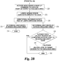
access node 50 is linked to the present/assigned location of the node and is used in processing any unlock request. For example, an access node on the fourth floor of a hotel in downtown Chicago may be assigned a unique hotel identifier coupled with a hotel zone identifier. Alternatively, the node may be assigned a single identifier which is then linked to its location by thewireless token 24 orserver 60. For purposes of illustrating the hierarchical relationship betweenaccess nodes 50 and the structures which fall within their range, a mock floor plan is shown inFIG 3 . The mock floor plan illustrates a number of complete circles which denote the wireless range of a number ofaccess nodes 50 for purposes of covering the entryway/hallway of a hotel floor and one or more doors. - According to the illustrated embodiment,
server 60 operates in conjunction withaccess node 50 overinternal network 54 to authenticate anywireless token 24 which comes within its range. In one form, when awireless token 24 comes within range of anaccess node 50, theaccess node 50 receives information from thewireless token 24 and seeks to identify one or more structures within its coverage area to which thewireless token 24 is authorized to enter. Theserver 60 serves to authenticate the request or a portion thereof using a reservations and occupancy database, while in other forms, theaccess node 50 may perform at least a portion of the authentication. In the illustrative embodiment,server 60 processes each request corresponding to an authentication request received byaccess node 50 fromwireless token 24, and upon proper authentication, confirms the authentication for one or more structures to accessnode 50 which then transmits an electronic signal to the corresponding lock(s), such aslock 34, notifying the lock to wake-up for a predetermined period of time in order to communication with nearby authorizedwireless token 24. In a further form, theaccess node 50 not only notifieslock 34 that it should wake-up, but also communicates information to lock 34 regarding whichwireless token 24 it should be expecting. - While
server 60 is described and illustrated as being a server, it should be understood thatserver 60 may be any computer, including a client server arrangement.Server 60 may interface withaccess node 50 by either a wireless or hardwired interconnection. Preferably, the connection is a secured connection. A non-limiting example list of potential interfaces includes IR, optical, RF, serial port, IP network, and USB. Additionally, the functions ofserver 60 andaccess node 50 may be integrated into one computer system. - Once
access node 50 as authenticatedwireless token 24 and woken-up a selectedlock 34, the process proceeds to a second level authentication between thewireless token 24 andlock 34. In the illustrated embodiment,wireless token 24 connects to lock 34 and provides authorization information. In one form, the authorization information provided may be the same as the authorization information provided bywireless token 24 to accessnode 50, described above. Alternatively, in another form, the authorization information provided bywireless node 24 may be unlock information provided towireless node 24 byaccess node 50 earlier in the process. Furthermore, in this form as well as other, upon receiving the authorization information fromwireless token 24,lock 34 may communicate withaccess node 50 to confirm the authorization orwireless token 24. In the event the authorization information received bylock 34 is authorized, by whatever means selected, lock 34 determines that a legitimate unlock request is present. - Additionally, either prior to or simultaneous with, lock 34 assesses the location of
wireless token 24 to determine whether it is within a designated area. For making this determination, lock 34 includes twodirectional antennas wireless token 24 over a low power wireless transmission protocol. As illustrated inFIG. 1 , according to the illustrated form, lock 34 andantennas door 32. According to the described form,antenna 38 faces outward fromdoor 32 andstructure 40 whileantenna 39 faces inward fromdoor 32 and intostructure 40. These antennas enablelock 34 to determine an approximate location ofwireless token 24 with respect to door 32 (i.e. inside or outside of structure 40) based upon a received signal strength indication (RSSI) determined by each ofdirectional antennas FIG. 3 illustrates a number of desired areas as small half circles outside of hotel room doors, which area the effective coverage areas for the required signal strength to be detected byantenna 38 with respect towireless token 24. It is only when awireless token 24 is within these areas that their respective doors may be opened if authorized. Furthermore, a number of larger half circles in the interior of the hotel rooms show the field of coverage ofantennas 39 which are used to detect when wireless token is within the corresponding hotel room. - Only after the authentication information received from
wireless token 24 is verified and the location ofwireless token 24 has been determined to be in the designated area will lock 34 unlock to permit the user access to the structure. - In still other embodiments, lock 34 is operably coupled to an override switch (not shown) having an access disable state. Asserting the override switch prevents the
access system 20 from permitting access to correspondingstructure 40. As one non-limiting example, the override switch may be asserted when a guest engages a deadbolt or bar latch within their hotel room. In some embodiments of theaccess system 20, the override switch is incorporated into an electronic control, not shown here, accessible to the user withinstructure 40. - A flowchart illustrating one set of steps performed in configuring a
wireless token 24 for use in accessing astructure 40 according to one embodiment of the present invention is shown inFIG. 2 . The process involves awireless token 24 and the various other components ofaccess system 20. The following description is with continuing reference to accesssystem 20 ofFIG. 1 . As shown inFIG. 1 , thewireless token 24 may be a dedicated wireless token or another device, such as a mobile telephone, laptop, tablet, or other portable electronic device; however, it is understood that numerous other networked appliances are also intended. - It shall be appreciated that initial reservation, check-in, and configuration information must be populated within
server 60 to enable to access methods described herein to be performed. For example, confirmation information stored byserver 60 preferably identifies the hotel and the user and includes a check-in/check-out date along with details of the type of room requested/reserved. In the preferred form, this confirmation information is received byserver 60 as a result of a hotel booking being made for a user either online, in person, or over the phone. - Upon checking into the hotel, or being authorized to access some other structure in other adaptations of the
system 20, thewireless token 24 is automatically configured to pair with or otherwise connect to access nodes located near thestructure 40. Additionally, the details of the assigned room or structure, including its number and location, are then stored byserver 60 is association withwireless token 24. This ensures thataccess nodes 50 will proper identify theroom wireless token 24 is assigned to access and be able to authenticate its request for access. It shall be appreciated that this process may be modified to accommodate more than one authorized hotel guest per room, such as having two wireless devices authorized to enter the same hotel room, or allowing a current guest to authorize the wireless device of another to access the hotel room for any portion of their remaining stay. - In continuing the description of the embodiment described with respect to
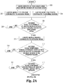
FIG. 2 , a flowchart illustrating one set of steps performed in allowing a user to accessstructure 40 usingwireless token 24 and the various other components ofaccess system 20 is shown. The following description is with continuing reference to accesssystem 20 ofFIG. 1 - As shown in
FIG. 2 , the process begins atstart point 200 with the user along with thewireless token 24 arriving in a location within range of anaccess node 50. Instep wireless token 24, are detected by theaccess node 50 respectively. Upon detecting the user device, the access node determines whether or not the user is authorized to enter one of the structure entrances that is proximate to access node 50 (step 206). If the user is not authorized, the process ends atpoint 208. If the user is authorized, the user device connects to the access node 50 (step 210). Next, in order to ensure that the user is on the proper floor, theaccess node 50 compares its perceived signal strength from the nearest access nodes of the floor above and below (if available) to ensure that its signal is the strongest (step 212). If the user is determined to be on another floor, the process proceeds to and ends atstep 214. Alternatively, if theaccess node 50 determines that the user is on its associated floor, the process proceeds to step 216. Instep 216 theaccess node 50 collaborates withserver 60 to confirm the credentials provided by the user device. In the event the credentials are not confirmed, the process ends atstep 218. If the credentials of the user device are confirmed, the process proceeds to step 220 whereaccess node 50 sends a wake-up signal to the lock, such aslock 34, associated with the structure, such asstructure 40, to which the user is authorized. Additionally, theaccess node 50 may detect the type of wireless standard the user device is capable of such that the proper wireless standard may be activated by the selecteddoor lock 34 instep 220. The wake-up signal may also include an access code, such as a temporary alphanumeric code or the like, which must be matched by the user device in order to cause the lock to open. - The second stage of the process beings in
step 226 where the user device connects to the nowactive lock 34. Thedual antennas lock 34 detect a RSSI from the user device (step 228). In the preferred form, the central focus of theantennas antennas antenna 39, the process proceeds throughsteps antenna 38 or a suitable ration, and at least a certain signal strength to indicate the desired proximity to lock 34 (step 236), the process proceeds to authenticate the request by comparing the security code provided by the user device to the stored access code received from node 50 (step 238) untillock 34 unlocks either provides the user with access to structure 40 (step 240) upon a successful authentication or the process ends at point 242. - In a further form,
door lock 34 takes appropriate samples of RSSI relative towireless token 24 on either side of door, usingantennas wireless token 24 is inside and outside ofdoor 32. Additionally, thelock 34 may use the RSSI samples ofantenna 38 to determine thedistance wireless token 24 is fromlock 34 for purposes of determining its presence within the defined proximity range outside of thedoor 32 as well. Once measurements averages are conducted, and presence of token/device and it is determined that he is in the proper unlock zone (range of outside proximity), the unlock of step 242 is granted. - In yet another form, lock 34 may periodically transmit information to access
node 50 for passing along toserver 60 which indicates the user is still in the hotel room. This information may trigger the in-room temperature to be maintained, and upon detecting that the user is no longer in the room, the temperature may be raised to a user-specified or standard level or it may trigger the lights to be turned off, as described inU.S. Patent Application 10/126,486 to Sunyich entitled "Personalized Smart Room", which is hereby incorporated by reference to the extent not inconsistent. - While the invention has been illustrated and described in detail in the drawings and foregoing description with respect to a hotel access system, the same is to be considered as illustrative and not restrictive in character. By way of non-limiting example, the system described herein may be applied to other enclosed areas where selective access is desired, including, other structures such as offices, amusement parks, military bases, restricted areas, vehicles, homes, etc.
Claims (13)
- An access system (20) allowing a user to access an enclosed area (40) using a wireless user device (24), the access system (20) comprising:a database adapted to store access permissions identifying at least one wireless user device authorized to access said enclosed area (40);a mechanical locking device (34) adapted to secure a point of entry (32) to said enclosed area (40), said mechanical locking device (34) operably connected to at least one short-range wireless receiver suitable for receiving an unlock request from said wireless user device (24) of the user and subsequently responding by granting access through said point of entry (32) when said unlock request is authorized using said database, characterized in thatwherein said at least one short-range wireless receiver includes a first and second directional antenna (38, 39), which are mounted to said point of entry (32), oriented such that the centers of the fields of reception of said first and second directional antennas are offset by an angle of at least 130 degrees, and configured to determine a received signal strength indicator for said wireless user device (24) of the user; andwherein said authorizing the unlock request requires a comparison of the received signal strength indicator for said wireless user device (24) of the user for each of said first and second directional antenna (38,39) such that the ratio of the received signal strength indicators indicates that said wireless user device (24) is outside of the enclosed area (40).
- The access system according to claim 1, wherein said at least one short-range wireless radio is a Bluetooth radio.
- The access system according to claim 1, wherein the centers of the fields of reception of said first and said second directional antennas (38, 39) are offset by an angle of at least 150 degrees.
- The access system according to claim 1, wherein said enclosed area (40) is a structure and (40) said point of entry is a door (32).
- The access system according to claim 4, wherein said mechanical locking device (34) is located in the mortise of said door (32).
- The access system according to claim 4, wherein at least one of said first and said second directional antennas (38, 39) is located in the mortise of said door (32).
- The access system according to claim 4, wherein said structure (40) is a hotel room.
- The access system according to claim 1, wherein said wireless user device (24) is a mobile telephone.
- A method of using an access system for granting access to an enclosed area to a user using a wireless user device (24), the method comprising the steps of:maintaining a database storing access permissions identifying at least one wireless user device (24); of the user authorized to access one or more enclosed areas (40);receiving a first unlock request for an identified enclosed area (40) at an access node (50) from the wireless user device (24) of the user, wherein at least one point of entry (32) of said enclosed area (40) is within the transmission range of said access node (50);authenticating at least a portion of said first unlock request using said database;transmitting a wake-up request and an access code from said access node to a short range wireless receiver operably connected to said mechanical locking device (34) securing a point of entry (32) to said identified enclosed area (40);receiving a second unlock request at said short range wireless receiver from the wireless user device (24) of the user, wherein said second unlock request includes a security code; andunlocking said mechanical lock device to provide access to said enclosed area in the event that said security code matches said access code, characterized in that the method further includes the steps of:determining a received signal strength indicator for said wireless user device for each of a first and second directional antenna (38, 39) mounted to said point of entry (32) and orientated such that the centers of the fields of reception of said first and said second directional antennas (38, 39) are offset by an angle of at least 130 degrees; andwherein said unlocking requires the step of comparing the received signal strength indicators for said wireless user device for each of said first and second directional antenna such that the ratio of the received (38, 39) signal strength indicators indicates that said wireless user device (24) of the user is outside of said enclosed area (40).
- The method for granting access according to claim 9, wherein the centers of the fields of reception of said first and said second directional antennas (38, 39) are offset by an angle of at least 150 degrees.
- The method for granting access according to claim 9, wherein said enclosed area (40) is a structure and said point of entry is a door (32).
- The method for granting access according to claim 11, wherein said mechanical locking device (34) is located in the mortise of said door (32).
- The method for granting access according to claim 12, wherein at least one of said first and said second directional antennas (38, 39) is located in the mortise of said door (32).
Applications Claiming Priority (2)
| Application Number | Priority Date | Filing Date | Title |
|---|---|---|---|
| US201161498169P | 2011-06-17 | 2011-06-17 | |
| PCT/US2012/042683 WO2012174387A2 (en) | 2011-06-17 | 2012-06-15 | System and method for accessing a structure using directional antennas and a wireless token |
Publications (3)
| Publication Number | Publication Date |
|---|---|
| EP2721871A2 EP2721871A2 (en) | 2014-04-23 |
| EP2721871A4 EP2721871A4 (en) | 2015-03-18 |
| EP2721871B1 true EP2721871B1 (en) | 2020-08-12 |
Family
ID=47357768
Family Applications (1)
| Application Number | Title | Priority Date | Filing Date |
|---|---|---|---|
| EP12799757.5A Active EP2721871B1 (en) | 2011-06-17 | 2012-06-15 | System and method for accessing a structure using directional antennas and a wireless token |
Country Status (7)
| Country | Link |
|---|---|
| US (1) | US20140125453A1 (en) |
| EP (1) | EP2721871B1 (en) |
| JP (1) | JP6552195B2 (en) |
| AU (1) | AU2012271443B2 (en) |
| CA (1) | CA2845510A1 (en) |
| ES (1) | ES2813355T3 (en) |
| WO (1) | WO2012174387A2 (en) |
Families Citing this family (29)
| Publication number | Priority date | Publication date | Assignee | Title |
|---|---|---|---|---|
| WO2012077993A2 (en) * | 2010-12-09 | 2012-06-14 | (주)지트론 | Door lock system |
| WO2013146564A1 (en) * | 2012-03-30 | 2013-10-03 | ソニー株式会社 | Terminal device, communication method, program, and communication system |
| US9485607B2 (en) * | 2013-05-14 | 2016-11-01 | Nokia Technologies Oy | Enhancing the security of short-range communication in connection with an access control device |
| US9888378B2 (en) * | 2013-06-27 | 2018-02-06 | International Business Machines Corporation | Associating a user identity to a wireless signal |
| US9373208B2 (en) * | 2013-09-11 | 2016-06-21 | Sony Corporation | Secure remote control for operating closures such as garage doors |
| US9948359B2 (en) * | 2013-09-20 | 2018-04-17 | At&T Intellectual Property I, L.P. | Secondary short-range wireless assist for wireless-based access control |
| FI125687B (en) * | 2013-10-01 | 2016-01-15 | Rollock Oy | Locking arrangement and method for determining the presence and position of a device transmitting a radio signal |
| US20150102903A1 (en) * | 2013-10-11 | 2015-04-16 | Wal-Mart Stores, Inc. | Secure Delivery Receptacle |
| US10126737B2 (en) | 2013-11-22 | 2018-11-13 | The Chamberlain Group, Inc. | Remotely operating a movable barrier operator with auxiliary device |
| SE538146C2 (en) | 2013-12-06 | 2016-03-15 | Sweden Connectivity Ab | Passive locking system including means for inside and outside detection |
| JP6478484B2 (en) * | 2014-05-22 | 2019-03-06 | 三菱電機株式会社 | Electric lock system and electric lock system control method |
| US9337951B2 (en) | 2014-07-31 | 2016-05-10 | Yousef Dhahi ALONAZY | Device and method for limiting an extent of a wireless network service |
| EP3072754A1 (en) | 2015-03-27 | 2016-09-28 | Assa Abloy AB | Method, device, computer program and computer program product for determining whether a portable key device is located in an active area in relation to a barrier |
| EP3073284A1 (en) | 2015-03-27 | 2016-09-28 | Assa Abloy AB | Method, device, computer program and computer program product for determining whether a portable key device is located in an active area in relation to a barrier |
| US9613478B2 (en) | 2015-05-18 | 2017-04-04 | Unikey Technologies Inc. | Wireless access control system for a door including door position based authentication and related methods |
| US9852561B2 (en) | 2015-05-18 | 2017-12-26 | Unikey Technologies Inc. | Wireless access control system for a door including proximity based lock disabling and related methods |
| US9858738B2 (en) | 2015-07-17 | 2018-01-02 | Wal-Mart Stores, Inc. | Apparatus and method to determine whether to unlock a delivered-package vault |
| CN105246030A (en) * | 2015-08-25 | 2016-01-13 | 深圳市一米阳光科技有限公司 | Automatic Bluetooth entrance/exit determination system and method |
| KR102323166B1 (en) * | 2015-11-23 | 2021-11-10 | 주식회사 슈프리마 | Method and system for managing a door entry using beacon signal |
| US9805533B2 (en) * | 2015-11-23 | 2017-10-31 | Suprema Inc. | Method and system for managing door access using beacon signal |
| US9697661B1 (en) * | 2015-12-28 | 2017-07-04 | Unikey Technologies Inc. | Wireless access control system including closed door position and exterior area remote access wireless communications device based lock switching and related methods |
| US9697658B1 (en) * | 2015-12-28 | 2017-07-04 | Unikey Technologies Inc. | Wireless access control system including closed door position and interior area remote access wireless communications device based lock switching and related methods |
| US10769877B2 (en) | 2017-03-02 | 2020-09-08 | OpenPath Security Inc. | Secure handsfree proximity-based access control |
| CN106968514A (en) * | 2017-03-29 | 2017-07-21 | 歌尔科技有限公司 | A kind of intelligent door lock |
| US10557300B2 (en) * | 2017-07-19 | 2020-02-11 | Amesbury Group, Inc. | Garage door access remote |
| CN109281545A (en) * | 2017-07-19 | 2019-01-29 | 雅帝科技股份有限公司 | Operate easy electronic lock |
| JP6931794B2 (en) | 2017-07-19 | 2021-09-08 | パナソニックIpマネジメント株式会社 | Drowsiness estimation device and awakening guidance device |
| US10599826B2 (en) | 2017-09-05 | 2020-03-24 | OpenPath Security Inc. | Decoupled authorization for restricted resource access |
| US10445956B2 (en) | 2017-09-05 | 2019-10-15 | OpenPath Security Inc. | Access control reader for secure handsfree access with mobile devices |
Family Cites Families (13)
| Publication number | Priority date | Publication date | Assignee | Title |
|---|---|---|---|---|
| JPH0688461A (en) * | 1992-09-07 | 1994-03-29 | Tokai Rika Co Ltd | Antenna for electric wave key receiver |
| CA2324679A1 (en) * | 2000-10-26 | 2002-04-26 | Lochisle Inc. | Method and system for physical access control using wireless connection to a network |
| US8462994B2 (en) * | 2001-01-10 | 2013-06-11 | Random Biometrics, Llc | Methods and systems for providing enhanced security over, while also facilitating access through, secured points of entry |
| JP2003315476A (en) * | 2002-04-24 | 2003-11-06 | Seiko Epson Corp | Timepiece |
| JP4510474B2 (en) * | 2004-01-20 | 2010-07-21 | 株式会社東海理化電機製作所 | Entrance / exit management system |
| US7446644B2 (en) * | 2005-01-14 | 2008-11-04 | Secureall Corporation | Universal hands free key and lock system |
| JP2006219925A (en) * | 2005-02-14 | 2006-08-24 | Matsushita Electric Ind Co Ltd | Lock control device, lock control system, and program |
| US20090289873A1 (en) * | 2007-12-19 | 2009-11-26 | Robert Schilling | Object direction indication through the use of multiple antenna beams |
| EP2235886B1 (en) * | 2007-12-31 | 2012-09-26 | Schlage Lock Company | Method and system for remotely controlling access to an access point |
| US20110065391A1 (en) * | 2008-05-27 | 2011-03-17 | Akihiko Shiotsuki | Wireless communication apparatus for changing directional pattern of variable directivity antenna according to variations in radio wave propagation enviroment |
| JP2010101711A (en) * | 2008-10-22 | 2010-05-06 | Rcs:Kk | Guidance support system for pedestrian |
| US8791790B2 (en) * | 2009-02-10 | 2014-07-29 | Yikes Llc | System and method for accessing a structure using a mobile device |
| JP5177684B2 (en) * | 2009-03-13 | 2013-04-03 | オムロンオートモーティブエレクトロニクス株式会社 | Vehicle communication apparatus and method, and program |
-
2012
- 2012-06-15 AU AU2012271443A patent/AU2012271443B2/en not_active Ceased
- 2012-06-15 WO PCT/US2012/042683 patent/WO2012174387A2/en unknown
- 2012-06-15 JP JP2014516036A patent/JP6552195B2/en not_active Expired - Fee Related
- 2012-06-15 ES ES12799757T patent/ES2813355T3/en active Active
- 2012-06-15 EP EP12799757.5A patent/EP2721871B1/en active Active
- 2012-06-15 CA CA2845510A patent/CA2845510A1/en not_active Abandoned
-
2013
- 2013-12-13 US US14/105,279 patent/US20140125453A1/en not_active Abandoned
Non-Patent Citations (1)
| Title |
|---|
| None * |
Also Published As
| Publication number | Publication date |
|---|---|
| WO2012174387A3 (en) | 2013-02-21 |
| JP2014522924A (en) | 2014-09-08 |
| EP2721871A2 (en) | 2014-04-23 |
| US20140125453A1 (en) | 2014-05-08 |
| JP6552195B2 (en) | 2019-07-31 |
| AU2012271443B2 (en) | 2016-05-12 |
| CA2845510A1 (en) | 2012-12-20 |
| WO2012174387A2 (en) | 2012-12-20 |
| EP2721871A4 (en) | 2015-03-18 |
| ES2813355T3 (en) | 2021-03-23 |
| AU2012271443A1 (en) | 2014-02-06 |
Similar Documents
| Publication | Publication Date | Title |
|---|---|---|
| EP2721871B1 (en) | System and method for accessing a structure using directional antennas and a wireless token | |
| US9501884B2 (en) | System and method for accessing a structure using directional antennas and a wireless token | |
| US9361741B2 (en) | System and method for accessing a structure using a mobile device | |
| US9336635B2 (en) | System and method for permitting secure access to a structure | |
| US9367975B2 (en) | System for permitting secure access to a restricted area | |
| US10085135B2 (en) | Radio frequency patch antenna and system for permitting secure access to a restricted area | |
| US9558604B2 (en) | System for permitting secure access to a restricted area | |
| US20100201536A1 (en) | System and method for accessing a structure using a mobile device | |
| EP3528214B1 (en) | Method for selectively opening a second lock from a first lock using short-range communications (src) | |
| US20190325677A1 (en) | Home security system with automatic authorization functionality | |
| US20220130190A1 (en) | Systems and methods for premises access control | |
| US11282318B1 (en) | Method of controlling access | |
| EP3561789A1 (en) | Improved home security system with automatic authorization functionality |
Legal Events
| Date | Code | Title | Description |
|---|---|---|---|
| PUAI | Public reference made under article 153(3) epc to a published international application that has entered the european phase |
Free format text: ORIGINAL CODE: 0009012 |
|
| 17P | Request for examination filed |
Effective date: 20131231 |
|
| AK | Designated contracting states |
Kind code of ref document: A2 Designated state(s): AL AT BE BG CH CY CZ DE DK EE ES FI FR GB GR HR HU IE IS IT LI LT LU LV MC MK MT NL NO PL PT RO RS SE SI SK SM TR |
|
| RIN1 | Information on inventor provided before grant (corrected) |
Inventor name: MCINTYRE, JIM, E. Inventor name: ROBERTSON, ANDREW, JOSEPH Inventor name: ROBERTSON, WILLIAM, BENJAMIN |
|
| DAX | Request for extension of the european patent (deleted) | ||
| A4 | Supplementary search report drawn up and despatched |
Effective date: 20150216 |
|
| RIC1 | Information provided on ipc code assigned before grant |
Ipc: H04W 48/04 20090101AFI20150210BHEP Ipc: G07C 9/00 20060101ALI20150210BHEP Ipc: H04W 12/06 20090101ALI20150210BHEP Ipc: B60R 25/24 20130101ALI20150210BHEP Ipc: E05B 53/00 20060101ALI20150210BHEP Ipc: H04W 4/08 20090101ALI20150210BHEP Ipc: H04W 4/00 20090101ALI20150210BHEP Ipc: H04W 12/08 20090101ALI20150210BHEP Ipc: H04W 4/04 20090101ALI20150210BHEP Ipc: H04L 29/06 20060101ALI20150210BHEP |
|
| STAA | Information on the status of an ep patent application or granted ep patent |
Free format text: STATUS: EXAMINATION IS IN PROGRESS |
|
| 17Q | First examination report despatched |
Effective date: 20180502 |
|
| REG | Reference to a national code |
Ref country code: DE Ref legal event code: R079 Ref document number: 602012071771 Country of ref document: DE Free format text: PREVIOUS MAIN CLASS: H04W0048040000 Ipc: H04W0012080000 |
|
| GRAP | Despatch of communication of intention to grant a patent |
Free format text: ORIGINAL CODE: EPIDOSNIGR1 |
|
| RIC1 | Information provided on ipc code assigned before grant |
Ipc: H04W 48/04 20090101ALI20200124BHEP Ipc: H04W 4/33 20180101ALI20200124BHEP Ipc: H04W 12/08 20090101AFI20200124BHEP Ipc: H04L 29/06 20060101ALI20200124BHEP |
|
| STAA | Information on the status of an ep patent application or granted ep patent |
Free format text: STATUS: GRANT OF PATENT IS INTENDED |
|
| INTG | Intention to grant announced |
Effective date: 20200305 |
|
| GRAS | Grant fee paid |
Free format text: ORIGINAL CODE: EPIDOSNIGR3 |
|
| GRAA | (expected) grant |
Free format text: ORIGINAL CODE: 0009210 |
|
| STAA | Information on the status of an ep patent application or granted ep patent |
Free format text: STATUS: THE PATENT HAS BEEN GRANTED |
|
| AK | Designated contracting states |
Kind code of ref document: B1 Designated state(s): AL AT BE BG CH CY CZ DE DK EE ES FI FR GB GR HR HU IE IS IT LI LT LU LV MC MK MT NL NO PL PT RO RS SE SI SK SM TR |
|
| REG | Reference to a national code |
Ref country code: GB Ref legal event code: FG4D |
|
| REG | Reference to a national code |
Ref country code: CH Ref legal event code: EP Ref country code: CH Ref legal event code: NV Representative=s name: ABREMA AGENCE BREVETS ET MARQUES, GANGUILLET, CH |
|
| REG | Reference to a national code |
Ref country code: IE Ref legal event code: FG4D |
|
| REG | Reference to a national code |
Ref country code: DE Ref legal event code: R096 Ref document number: 602012071771 Country of ref document: DE |
|
| REG | Reference to a national code |
Ref country code: AT Ref legal event code: REF Ref document number: 1302783 Country of ref document: AT Kind code of ref document: T Effective date: 20200915 |
|
| REG | Reference to a national code |
Ref country code: SE Ref legal event code: TRGR |
|
| REG | Reference to a national code |
Ref country code: LT Ref legal event code: MG4D |
|
| REG | Reference to a national code |
Ref country code: NL Ref legal event code: MP Effective date: 20200812 |
|
| PG25 | Lapsed in a contracting state [announced via postgrant information from national office to epo] |
Ref country code: FI Free format text: LAPSE BECAUSE OF FAILURE TO SUBMIT A TRANSLATION OF THE DESCRIPTION OR TO PAY THE FEE WITHIN THE PRESCRIBED TIME-LIMIT Effective date: 20200812 Ref country code: NO Free format text: LAPSE BECAUSE OF FAILURE TO SUBMIT A TRANSLATION OF THE DESCRIPTION OR TO PAY THE FEE WITHIN THE PRESCRIBED TIME-LIMIT Effective date: 20201112 Ref country code: GR Free format text: LAPSE BECAUSE OF FAILURE TO SUBMIT A TRANSLATION OF THE DESCRIPTION OR TO PAY THE FEE WITHIN THE PRESCRIBED TIME-LIMIT Effective date: 20201113 Ref country code: LT Free format text: LAPSE BECAUSE OF FAILURE TO SUBMIT A TRANSLATION OF THE DESCRIPTION OR TO PAY THE FEE WITHIN THE PRESCRIBED TIME-LIMIT Effective date: 20200812 Ref country code: BG Free format text: LAPSE BECAUSE OF FAILURE TO SUBMIT A TRANSLATION OF THE DESCRIPTION OR TO PAY THE FEE WITHIN THE PRESCRIBED TIME-LIMIT Effective date: 20201112 Ref country code: HR Free format text: LAPSE BECAUSE OF FAILURE TO SUBMIT A TRANSLATION OF THE DESCRIPTION OR TO PAY THE FEE WITHIN THE PRESCRIBED TIME-LIMIT Effective date: 20200812 |
|
| REG | Reference to a national code |
Ref country code: AT Ref legal event code: MK05 Ref document number: 1302783 Country of ref document: AT Kind code of ref document: T Effective date: 20200812 |
|
| PG25 | Lapsed in a contracting state [announced via postgrant information from national office to epo] |
Ref country code: PL Free format text: LAPSE BECAUSE OF FAILURE TO SUBMIT A TRANSLATION OF THE DESCRIPTION OR TO PAY THE FEE WITHIN THE PRESCRIBED TIME-LIMIT Effective date: 20200812 Ref country code: LV Free format text: LAPSE BECAUSE OF FAILURE TO SUBMIT A TRANSLATION OF THE DESCRIPTION OR TO PAY THE FEE WITHIN THE PRESCRIBED TIME-LIMIT Effective date: 20200812 Ref country code: NL Free format text: LAPSE BECAUSE OF FAILURE TO SUBMIT A TRANSLATION OF THE DESCRIPTION OR TO PAY THE FEE WITHIN THE PRESCRIBED TIME-LIMIT Effective date: 20200812 Ref country code: RS Free format text: LAPSE BECAUSE OF FAILURE TO SUBMIT A TRANSLATION OF THE DESCRIPTION OR TO PAY THE FEE WITHIN THE PRESCRIBED TIME-LIMIT Effective date: 20200812 Ref country code: IS Free format text: LAPSE BECAUSE OF FAILURE TO SUBMIT A TRANSLATION OF THE DESCRIPTION OR TO PAY THE FEE WITHIN THE PRESCRIBED TIME-LIMIT Effective date: 20201212 |
|
| REG | Reference to a national code |
Ref country code: ES Ref legal event code: FG2A Ref document number: 2813355 Country of ref document: ES Kind code of ref document: T3 Effective date: 20210323 |
|
| PG25 | Lapsed in a contracting state [announced via postgrant information from national office to epo] |
Ref country code: CZ Free format text: LAPSE BECAUSE OF FAILURE TO SUBMIT A TRANSLATION OF THE DESCRIPTION OR TO PAY THE FEE WITHIN THE PRESCRIBED TIME-LIMIT Effective date: 20200812 Ref country code: EE Free format text: LAPSE BECAUSE OF FAILURE TO SUBMIT A TRANSLATION OF THE DESCRIPTION OR TO PAY THE FEE WITHIN THE PRESCRIBED TIME-LIMIT Effective date: 20200812 Ref country code: DK Free format text: LAPSE BECAUSE OF FAILURE TO SUBMIT A TRANSLATION OF THE DESCRIPTION OR TO PAY THE FEE WITHIN THE PRESCRIBED TIME-LIMIT Effective date: 20200812 Ref country code: RO Free format text: LAPSE BECAUSE OF FAILURE TO SUBMIT A TRANSLATION OF THE DESCRIPTION OR TO PAY THE FEE WITHIN THE PRESCRIBED TIME-LIMIT Effective date: 20200812 Ref country code: SM Free format text: LAPSE BECAUSE OF FAILURE TO SUBMIT A TRANSLATION OF THE DESCRIPTION OR TO PAY THE FEE WITHIN THE PRESCRIBED TIME-LIMIT Effective date: 20200812 |
|
| REG | Reference to a national code |
Ref country code: DE Ref legal event code: R097 Ref document number: 602012071771 Country of ref document: DE |
|
| PG25 | Lapsed in a contracting state [announced via postgrant information from national office to epo] |
Ref country code: AL Free format text: LAPSE BECAUSE OF FAILURE TO SUBMIT A TRANSLATION OF THE DESCRIPTION OR TO PAY THE FEE WITHIN THE PRESCRIBED TIME-LIMIT Effective date: 20200812 Ref country code: AT Free format text: LAPSE BECAUSE OF FAILURE TO SUBMIT A TRANSLATION OF THE DESCRIPTION OR TO PAY THE FEE WITHIN THE PRESCRIBED TIME-LIMIT Effective date: 20200812 |
|
| PLBE | No opposition filed within time limit |
Free format text: ORIGINAL CODE: 0009261 |
|
| STAA | Information on the status of an ep patent application or granted ep patent |
Free format text: STATUS: NO OPPOSITION FILED WITHIN TIME LIMIT |
|
| PG25 | Lapsed in a contracting state [announced via postgrant information from national office to epo] |
Ref country code: SK Free format text: LAPSE BECAUSE OF FAILURE TO SUBMIT A TRANSLATION OF THE DESCRIPTION OR TO PAY THE FEE WITHIN THE PRESCRIBED TIME-LIMIT Effective date: 20200812 |
|
| 26N | No opposition filed |
Effective date: 20210514 |
|
| PG25 | Lapsed in a contracting state [announced via postgrant information from national office to epo] |
Ref country code: IT Free format text: LAPSE BECAUSE OF FAILURE TO SUBMIT A TRANSLATION OF THE DESCRIPTION OR TO PAY THE FEE WITHIN THE PRESCRIBED TIME-LIMIT Effective date: 20200812 |
|
| PG25 | Lapsed in a contracting state [announced via postgrant information from national office to epo] |
Ref country code: SI Free format text: LAPSE BECAUSE OF FAILURE TO SUBMIT A TRANSLATION OF THE DESCRIPTION OR TO PAY THE FEE WITHIN THE PRESCRIBED TIME-LIMIT Effective date: 20200812 |
|
| PGFP | Annual fee paid to national office [announced via postgrant information from national office to epo] |
Ref country code: CH Payment date: 20210616 Year of fee payment: 10 Ref country code: SE Payment date: 20210610 Year of fee payment: 10 |
|
| PGFP | Annual fee paid to national office [announced via postgrant information from national office to epo] |
Ref country code: ES Payment date: 20210708 Year of fee payment: 10 |
|
| REG | Reference to a national code |
Ref country code: DE Ref legal event code: R119 Ref document number: 602012071771 Country of ref document: DE |
|
| PG25 | Lapsed in a contracting state [announced via postgrant information from national office to epo] |
Ref country code: MC Free format text: LAPSE BECAUSE OF FAILURE TO SUBMIT A TRANSLATION OF THE DESCRIPTION OR TO PAY THE FEE WITHIN THE PRESCRIBED TIME-LIMIT Effective date: 20200812 |
|
| GBPC | Gb: european patent ceased through non-payment of renewal fee |
Effective date: 20210615 |
|
| REG | Reference to a national code |
Ref country code: BE Ref legal event code: MM Effective date: 20210630 |
|
| PG25 | Lapsed in a contracting state [announced via postgrant information from national office to epo] |
Ref country code: LU Free format text: LAPSE BECAUSE OF NON-PAYMENT OF DUE FEES Effective date: 20210615 |
|
| PG25 | Lapsed in a contracting state [announced via postgrant information from national office to epo] |
Ref country code: IE Free format text: LAPSE BECAUSE OF NON-PAYMENT OF DUE FEES Effective date: 20210615 Ref country code: GB Free format text: LAPSE BECAUSE OF NON-PAYMENT OF DUE FEES Effective date: 20210615 Ref country code: DE Free format text: LAPSE BECAUSE OF NON-PAYMENT OF DUE FEES Effective date: 20220101 |
|
| PG25 | Lapsed in a contracting state [announced via postgrant information from national office to epo] |
Ref country code: FR Free format text: LAPSE BECAUSE OF NON-PAYMENT OF DUE FEES Effective date: 20210630 |
|
| PG25 | Lapsed in a contracting state [announced via postgrant information from national office to epo] |
Ref country code: BE Free format text: LAPSE BECAUSE OF NON-PAYMENT OF DUE FEES Effective date: 20210630 |
|
| REG | Reference to a national code |
Ref country code: CH Ref legal event code: PL Ref country code: SE Ref legal event code: EUG |
|
| PG25 | Lapsed in a contracting state [announced via postgrant information from national office to epo] |
Ref country code: SE Free format text: LAPSE BECAUSE OF NON-PAYMENT OF DUE FEES Effective date: 20220616 Ref country code: PT Free format text: LAPSE BECAUSE OF FAILURE TO SUBMIT A TRANSLATION OF THE DESCRIPTION OR TO PAY THE FEE WITHIN THE PRESCRIBED TIME-LIMIT Effective date: 20201214 Ref country code: LI Free format text: LAPSE BECAUSE OF NON-PAYMENT OF DUE FEES Effective date: 20220630 Ref country code: CH Free format text: LAPSE BECAUSE OF NON-PAYMENT OF DUE FEES Effective date: 20220630 |
|
| PG25 | Lapsed in a contracting state [announced via postgrant information from national office to epo] |
Ref country code: HU Free format text: LAPSE BECAUSE OF FAILURE TO SUBMIT A TRANSLATION OF THE DESCRIPTION OR TO PAY THE FEE WITHIN THE PRESCRIBED TIME-LIMIT; INVALID AB INITIO Effective date: 20120615 Ref country code: CY Free format text: LAPSE BECAUSE OF FAILURE TO SUBMIT A TRANSLATION OF THE DESCRIPTION OR TO PAY THE FEE WITHIN THE PRESCRIBED TIME-LIMIT Effective date: 20200812 |
|
| REG | Reference to a national code |
Ref country code: ES Ref legal event code: FD2A Effective date: 20230804 |
|
| PG25 | Lapsed in a contracting state [announced via postgrant information from national office to epo] |
Ref country code: ES Free format text: LAPSE BECAUSE OF NON-PAYMENT OF DUE FEES Effective date: 20220616 |