EP3071848B1 - Vorrichtung zur montage an der karosserie eines fahrzeugs - Google Patents
Vorrichtung zur montage an der karosserie eines fahrzeugs Download PDFInfo
- Publication number
- EP3071848B1 EP3071848B1 EP14808481.7A EP14808481A EP3071848B1 EP 3071848 B1 EP3071848 B1 EP 3071848B1 EP 14808481 A EP14808481 A EP 14808481A EP 3071848 B1 EP3071848 B1 EP 3071848B1
- Authority
- EP
- European Patent Office
- Prior art keywords
- bottom part
- vehicle
- configuration
- upper housing
- flexible
- Prior art date
- Legal status (The legal status is an assumption and is not a legal conclusion. Google has not performed a legal analysis and makes no representation as to the accuracy of the status listed.)
- Not-in-force
Links
- 239000000463 material Substances 0.000 claims description 20
- 239000007779 soft material Substances 0.000 claims description 20
- 238000000034 method Methods 0.000 claims description 11
- 239000004677 Nylon Substances 0.000 claims description 6
- 229920001778 nylon Polymers 0.000 claims description 6
- 229920000642 polymer Polymers 0.000 claims description 6
- 238000003825 pressing Methods 0.000 claims description 3
- 239000002131 composite material Substances 0.000 claims description 2
- 239000004033 plastic Substances 0.000 claims description 2
- 230000007246 mechanism Effects 0.000 description 10
- 238000003780 insertion Methods 0.000 description 3
- 230000037431 insertion Effects 0.000 description 3
- 230000004913 activation Effects 0.000 description 2
- 238000000465 moulding Methods 0.000 description 2
- 230000008569 process Effects 0.000 description 2
- 238000004804 winding Methods 0.000 description 2
- 230000008859 change Effects 0.000 description 1
- 230000008878 coupling Effects 0.000 description 1
- 238000010168 coupling process Methods 0.000 description 1
- 238000005859 coupling reaction Methods 0.000 description 1
- 230000001419 dependent effect Effects 0.000 description 1
- 230000007774 longterm Effects 0.000 description 1
- 238000004519 manufacturing process Methods 0.000 description 1
- 238000003860 storage Methods 0.000 description 1
Images



Classifications
-
- B—PERFORMING OPERATIONS; TRANSPORTING
- B60—VEHICLES IN GENERAL
- B60R—VEHICLES, VEHICLE FITTINGS, OR VEHICLE PARTS, NOT OTHERWISE PROVIDED FOR
- B60R9/00—Supplementary fittings on vehicle exterior for carrying loads, e.g. luggage, sports gear or the like
- B60R9/04—Carriers associated with vehicle roof
- B60R9/058—Carriers associated with vehicle roof characterised by releasable attaching means between carrier and roof
-
- B—PERFORMING OPERATIONS; TRANSPORTING
- B60—VEHICLES IN GENERAL
- B60R—VEHICLES, VEHICLE FITTINGS, OR VEHICLE PARTS, NOT OTHERWISE PROVIDED FOR
- B60R9/00—Supplementary fittings on vehicle exterior for carrying loads, e.g. luggage, sports gear or the like
- B60R9/04—Carriers associated with vehicle roof
-
- F—MECHANICAL ENGINEERING; LIGHTING; HEATING; WEAPONS; BLASTING
- F16—ENGINEERING ELEMENTS AND UNITS; GENERAL MEASURES FOR PRODUCING AND MAINTAINING EFFECTIVE FUNCTIONING OF MACHINES OR INSTALLATIONS; THERMAL INSULATION IN GENERAL
- F16B—DEVICES FOR FASTENING OR SECURING CONSTRUCTIONAL ELEMENTS OR MACHINE PARTS TOGETHER, e.g. NAILS, BOLTS, CIRCLIPS, CLAMPS, CLIPS OR WEDGES; JOINTS OR JOINTING
- F16B47/00—Suction cups for attaching purposes; Equivalent means using adhesives
- F16B47/006—Suction cups for attaching purposes; Equivalent means using adhesives the suction cups being activated by the rotation of a cranked lever arm
Definitions
- the present invention relates in a first aspect to a system for mounting on the surface of the body of a vehicle for securing one or more items to a vehicle.
- the present invention relates to the use of a system according to the first aspect.
- the present invention relates to a method of securing goods on or in a vehicle.
- a carrying rack which enables fastening larger items or goods on the top of the vehicle, thus allowing transportation of goods which in itself is too large to accommodate in the cabin of the car.
- a carrying rack may comprise a set of two rails which are adapted to be mounted in the drip moulding of the car.
- such a rack may comprise a frame extending in a width approximately corresponding to the width of the roof of the vehicle, and extending in a longitudinal direction corresponding to approximately the length of the roof of the vehicle.
- US 6 059 010 discloses a roller sunshade which is adapted to be easily mounted on and dismounted from a car roof without the need of any tools.
- the roller sunshade comprises more than one sucker mechanism and an automatic sunshade winding mechanism.
- Each sucker mechanism is adapted to be mounted on the car roof by vacuum suction in that the sucker mechanism comprises a main body having a flexible lower disc portion which is intended to come into contact with the car roof and which is intended to shift its configuration between a flat and a curved configuration by the turn of a handling bar, thereby allowing creation of a vacuum between the lower disc portion and the car roof.
- the upper part of the main body of the sucker mechanism comprises a seat having an insertion opening for receiving a supporting bar for the sunshade winding mechanism.
- US 6 059 010 does not relate to a system for securing goods to the top of a vehicle. Moreover, once dismounted from the car roof the roller sunshade is still having its original long extention in one direction, making it difficult to accommodate in the interior of a car when not in use.
- EP 2 302 235 A1 discloses a vacuum suction device.
- the device comprises a support shell and an associated flexible suction cup as well as an actuating mechanism which upon actuation acts on the suction cup in order to produce a vacuum between the suction cup and a surface facing the suction cup.
- the actuation of the actuation mechanism provides changing of the suction cup via a coupling mechanism from an engaged configuration providing a vacuum and a disengaged configuration providing no vacuum.
- the device comprises means which may provide a partial vacuum beneath the suction cup.
- the device is primarily for use as a lifting device or for use as a handle for example in a bathroom.
- EP 2 302 235 A1 does not disclose that the device comprises any fastening means for the purpose of tethering items to the device.
- the present invention relates to a system comprising one or more devices and one or more brackets, wherein each said device is for mounting on the surface of the body of a vehicle for securing one or more items to a vehicle; said device in the orientation intended for use comprising:
- the one or more brackets is comprising an elongate rail; and that said attachment means is/are arranged at an end of said rail or at a middle part of said rail; said rail is a telescopic rail being adapted to shift its configuration between an extracted configuration and a contracted configuration.
- the present invention relates to a use of a system according to the first aspect of the present invention for securing one or more items to a vehicle.
- the present invention relates to a method of securing goods to a vehicle, said method comprising:
- the invention according to the first, the second, and the third aspect provides for a smaller and more useable and flexible means for securing items to a vehicle.
- the invention is advantageous as a supplementary fixation point for goods being transported on a prior art roof rack in that the device according to the first aspect of the present invention may be fixed on the surface of a body of a vehicle, and subsequently a line or rope may be tethered between the hole of the device and the goods to be transported.
- the invention implies the advantages that, in contrast to the prior art roof racks, it can be easily and fast mounted on and dismounted from a surface of a vehicle, even if performed singlehanded.
- the system of the invention allows building up on the surface of the body of a vehicle a rack-like system which better allows for attachment of goods and/or items.
- the present invention relates to a system comprising one or more devices and one or more brackets, wherein each said device is for mounting on the surface of the body of a vehicle for securing one or more items to a vehicle; said device in the orientation intended for use comprising:
- the one or more brackets is comprising an elongate rail; and that said attachment means is/are arranged at an end of said rail or at a middle part of said rail; said rail is a telescopic rail being adapted to shift its configuration between an extracted configuration and a contracted configuration.
- the system may be suitable for fixing onto any smooth, relatively planar surface.
- the device is disclosed with special attention to the use on the surface of a body of a vehicle, such as a car.
- the device of the system comprises an upper housing made of a relatively hard material and a bottom part made of a flexible, relatively soft material.
- the term "in the orientation intended for use” shall be understood to mean in an orientation in which the device of the system is fastened upon the roof of a vehicle and in which the upper housing in oriented above the bottom part of a flexible, relatively soft material.
- the term "in the orientation intended for use” shall within the meaning defined above not in any way exclude the use or suitability of arranging the device in any other orientation.
- the soft material is configured to change curvature, by actuation thereof, from a disengaged configuration, in which a bottom surface of the bottom part is essentially planar, to an engaged configuration, in which the bottom surface of the bottom part is concave.
- actuation will allow the device of the system to be sucked and fixed onto a smooth and relatively planer surface, such as the surface of the body of a vehicle.
- the upper housing of the device of the system comprises one or more through going holes for providing means for securing one or more items to said vehicle. Accordingly, once being sucked to a smooth and relatively planer surface, goods and/or items may be fastened to the one or more through-going holes of the device.
- the bottom part of a flexible, relatively soft material of the device of the system is having a circular or essentially circular circumference.
- Such a geometry of the bottom part will better allow the bottom part to attain a concave configuration.
- the surface area of the bottom surface of the bottom part of a flexible, relatively soft material of the device of the system is 75 - 700 cm 2 , such as 100 - 675 cm 2 , for example 125 - 650 cm 2 , e.g. 150 - 625 cm 2 , for example 175 - 600 cm 2 , such as 200 - 575 cm 2 , e.g. 225 - 550 cm 2 , such as 250 - 525 cm 2 ,e.g. 275 - 500 cm 2 , for example 300 - 475 cm 2 , such as 325 - 450 cm 2 , e.g. 350 - 425 cm 2 , such as 375 - 400 cm 2 .
- the upper housing of the device of the system is made of a polymer or polymer composite material, such as nylon or nylon-based material, i.e. nylon mixed with other material(s).
- the bottom part of the device of the system is made of a flexible, relatively soft material is made of a polymer, such as rubber or a plastic.
- the actuator means of the device of the system comprises a lever having a first end and a second end, wherein said lever at a position near its first end being pivotally mounted in said upper housing, wherein said lever, preferable near its first end, being mechanically connected to an actuation rod extending downwardly and being mechanically connected to the bottom part of said device, said actuation rod preferably being connected to a central part of bottom part of said device of said system.
- This design provides for a mechanically strong actuator which at the same time is easy to handle upon engaging and disengaging the bottom part of the device.
- the flexible, relatively soft material of the bottom part of the device of the system in its interior comprises a relative stiff sheet material; and wherein said actuation rod being mechanically connected to said relative stiff sheet material.
- This embodiment provides for a strong attachment of the actuation rod to the bottom part.
- the device of the system comprising a lock for locking against theft of said actuator, said lock being configured to lock said actuator means in its engaged configuration, in which the bottom surface of the bottom part is concave; and wherein said lock optionally also being configured to allow locking of said actuator means in its disengaged configuration, in which the bottom surface of the bottom part is essentially planar.
- Locks make it possible to leave a vehicle with one or more devices attached to the body in an engaged configuration without the risk of theft.
- the one or more through going holes provided in the upper housing of the device of the system is having a cross-sectional area of 1 - 30 cm 2 , such as 2 - 28 cm 2 , e.g. 4 - 26 cm 2 , such as 6 - 24 cm 2 , for example 8 - 22 cm 2 , e.g. 10 - 20 cm 2 , such as 12 - 18 cm 2 or 14 - 16 cm 2 .
- Such cross-sectional areas of the one or more through going holes provided in the upper housing provide easy access when attaching a tethering or a line or the like to the one or more through going holes.
- the lever of the device of the system is being spring loaded by a spring.
- Spring loading the lever may imply that a user upon engaging applies more pressure to the device and thus provides better contact between the lower surface of the bottom part and the surface upon which the devise is intended to be attached.
- the attachment means comprises a snap on lock for being releasable attached to said one or more through going holes in said upper part of said device of said system.
- a snap lock allows for fast and easy attachment of a bracket to a device.
- the system comprises a separate fixation part for fixation of the bracket, said device being configured to receive said fixation part from the opposite side of the through going hole, compared to the side from which the bracket is received.
- the fixation part serves the purpose of locking the bracket so that it does not loosen accidentally.
- the system comprises two or more brackets.
- Two or more brackets better allows for attachment of goods and/or items.
- the telescopic rail included in the system allows for minimizing the space necessary to store the system when not in use.
- the system comprises telescopic rail(s)
- the user may easily find storage space for the system inside the vehicle, when not in use for tethering goods or items.
- the present invention relates to the use of a system according to the first aspect for securing one or more items to a vehicle.
- the present invention relates to a method of securing goods to a vehicle, said method comprising:
- one or more systems according to the first aspect of the invention is provided, in step i); and in this step vi) said one or more items optionally being tethered to said bracket(s) or said rails of said system.
- FIG. 1a two types of a prior art roof rack for a vehicle is illustrated in Fig. 1a and lb, respectively.
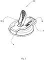
- Fig. 2 shows in a perspective view a device 100 to be used in the system of the first aspect of the present invention.
- the device is intended for mounting on the surface of the body of a vehicle for securing one or more items to said vehicle.
- the device in the orientation intended for use comprising: an upper housing 2 and a bottom part 4.
- the upper housing 2 is made of a relatively hard material; and bottom part 4 is made of a flexible, relatively soft material.
- the upper housing is provided with a thorough going hole for providing means for securing one or more items to said vehicle. 2, 3, 4, 5 or even more holes may also be provided.
- Fig 2 also shows that actuator means 10 in the form of a lever 14 is pivotally mounted on the upper housing 2 of the device 100.
- the lever is mechanically attached to the bottom part 4 of the flexible, relatively soft material in such a way that by activation of the lever, the bottom part may shift its configuration between a disengaged configuration, in which the bottom surface 6 of the bottom part 4 is essentially planar, and an engaged configuration, in which the bottom surface 6 of the bottom part 4 is concave.
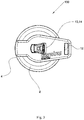
- Fig 3 shows the device 100 of fig. 2 as seen from above.
- fig. 4 shows a cross-sectional view of the device of fig. 2 .
- Fig. 4 shows the device 100 comprising the upper housing 2 and a bottom part 4 which comprises a bottom surface 6 and a top surface 8.
- the bottom part is made of a flexible, relatively soft material which is capable of switching its configuration between a disengaged configuration, in which the bottom surface 6 of the bottom part 4 is essentially planar, and an engaged configuration, in which the bottom surface 6 of the bottom part 4 is concave.
- the bottom part 4 comprises in its interior a relatively rigid sheet material 22 which is mechanically connected to an actuation rod 20 which at its opposite end is connected to a first end 16 of a lever 14.
- the lever is pivotally mounted to the upper housing.
- a spring 26 for spring loading the bottom part is arranged between the top surface of the bottom part 4 and the first end of the lever.
- the lifting of the bottom part 4 will establish a vacuum between said surface of said vehicle and said bottom surface 6 of the bottom part 4.
- the established vacuum will ensure safe and long term fastening of the device 100 to the surface of the body of the vehicle.
- the previously established vacuum will be pressure equalized to the surrounding pressure. This means that the device 100 can be removed from the surface of the body of the vehicle.
- Fig. 5 shows a system according to the first aspect of the present invention.
- the system depicted in fig. 5 comprises a device 100 as shown in fig. 2 , 3 and 4 in combination with a bracket 300.
- the bracket 300 is releasable attached to the through going hole 12 in the upper housing 2 of the device 100.
- a fixation part 29 is mounted in the opposite side of the hole12, compared to the side from which the bracket 300 is received. The fixation part 29 secures that the bracket will not accidentally and unintentionally be released during transport of goods.
- the rail 400 comprises an oblong element which is fixed to the bracket at its middle part.
- the rail serves the purpose of being a support for goods to be transported.
- attachment means of the bracket 300 is show in fig. 6a and in a close-up view in fig. 6b .
- the attachment means 28 of the bracket 300 comprises two spaced-apart arms 28 arranged at the end of the bracket 300.
- the arms are flexible and may be bended against each other upon insertion into the hole 12 of the upper housing 2 of the device 100. Upon full insertion of these arms 28 the arms will lock themselves into a locked position by engaging against the material of the upper housing defining the edge of the hole 12.
- a fixation part 29 is subsequently inserted into the hole 12 from the below, opposite side of the hole. This ensures that the two arms 28 cannot be bended and thus secures that the bracket 300 will not be unintentionally released.
Landscapes
- Engineering & Computer Science (AREA)
- Mechanical Engineering (AREA)
- General Engineering & Computer Science (AREA)
- Fittings On The Vehicle Exterior For Carrying Loads, And Devices For Holding Or Mounting Articles (AREA)
- Connection Of Plates (AREA)
Claims (15)
- System (200), das eine oder mehrere Vorrichtungen (100) und eine oder mehrere Klammern (300) umfasst, wobei jede diese Vorrichtung (100) zum Befestigen an der Oberfläche der Karosserie eines Fahrzeugs zum Sichern eines oder mehrerer Gegenstände an einem Fahrzeug ist; die Vorrichtung in der zur Verwendung vorgesehenen Ausrichtung umfassend:ein oberes Gehäuse (2), das aus einem relativ harten Material hergestellt ist;ein Unterteil (4), das aus einem flexiblen, relativ weichen Material hergestellt ist, wobei das flexible, relativ weiche Material eine untere Oberfläche (6) und eine obere Oberfläche (8) umfasst;wobei das Unterteil (4) konfiguriert ist, um seine Konfiguration zwischen einer gelösten Konfiguration, in der die untere Oberfläche (6) des Unterteils (4) im Wesentlichen eben ist, und einer Eingriffskonfiguration wechseln zu können, in der die untere Oberfläche (6) des Unterteils (4) konkav ist;wobei das obere Gehäuse ein Betätigungsmittel (10) zum Betätigen des Unterteils zum Wechseln der Konfiguration des Unterteils zwischen der gelösten Konfiguration und der Eingriffskonfiguration umfasst;wobei das Betätigungsmittel (10) konfiguriert ist, um das Unterteil in der Eingriffskonfiguration zu halten, bis es in eine gelöste Konfiguration gelöst wird;wobei das obere Gehäuse eine oder mehrere durchgehende Löcher (12) zum Bereitstellen von Mitteln zum Sichern eines oder mehrerer Gegenstände an einem Fahrzeug umfasst;wobei die eine oder mehreren Klammern Befestigungsmittel (28) umfassen, das/die konfiguriert ist/sind, um an der einen oder den mehreren von den durchgehenden Löchern (12) in dem oberen Gehäuse (2) der Vorrichtung entfernbar befestigt zu werden;wobei die eine oder mehreren Klammern eine längliche Schiene (400) umfassen und wobei das/die Befestigungsmittel an einem Ende der Schiene oder in einem mittleren Teil der Schiene angeordnet ist/sind;dadurch gekennzeichnet, dass die Schiene eine teleskopische Schiene ist, die angepasst ist, um ihre Konfiguration zwischen einer ausgezogenen Konfiguration und einer zusammengezogenen Konfiguration zu wechseln.
- System nach Anspruch 1, wobei das Unterteil (4) aus einem flexiblen, relativ weichen Material der Vorrichtung einen kreisförmigen oder im Wesentlichen kreisförmigen Umfang hat.
- System nach Anspruch 1 oder 2, wobei die Fläche der unteren Oberfläche (6) des Unterteils (4) aus einem flexiblen, relativ weichen Material der Vorrichtung 75 - 700 cm2, wie etwa 100 - 675 cm2, beispielsweise 125-650 cm2, z.B. 150 - 625 cm2, beispielsweise 175 - 600 cm2, wie etwa 200 - 575 cm2, z.B. 225 - 550 cm2, wie etwa 250 - 525 cm2, z.B. 275 - 500 cm2, beispielsweise 300 - 475 cm2, wie etwa 325 - 450 cm2, z.B. 350 - 425 cm2, wie etwa 375 - 400 cm2 ist.
- System nach einem der vorstehenden Ansprüche, wobei das obere Gehäuse (2) der Vorrichtung aus einem Polymer oder Polymerverbundmaterial, wie etwa Nylon oder einem Nylon-basierten Material, d.h. Nylon gemischt mit anderen Material(ien), hergestellt ist; und/oder wobei das Unterteil (4) aus einem flexiblen, relativ weichen Material der Vorrichtung aus einem Polymer, wie etwa Gummi oder Kunststoff, hergestellt ist.
- System nach einem der vorstehenden Ansprüche, wobei das Betätigungsmittel der Vorrichtung (10) einen Hebel (14) mit einem ersten Ende (16) und einem zweiten Ende (18) umfasst, wobei der Hebel in einer Position in der Nähe seines ersten Endes in dem oberen Gehäuse schwenkbar befestigt ist, wobei der Hebel, bevorzugt in der Nähe seines ersten Endes, mechanisch mit einer Betätigungsstange (20) verbunden ist, die sich nach unten erstreckt und mechanisch mit dem Unterteil (4) der Vorrichtung verbunden ist, wobei die Betätigungsstange bevorzugt mit einem zentralen Teil des Unterteils der Vorrichtung verbunden ist.
- System nach einem der vorstehenden Ansprüche, wobei das flexible, relativ weiche Material der Vorrichtung in seinem Inneren ein relativ steifes Plattenmaterial (22) umfasst und wobei die Betätigungsstange mechanisch mit dem relativ steifen Plattenmaterial verbunden ist.
- System nach einem der vorstehenden Ansprüche, wobei die Vorrichtung eine Verriegelung (24) zum Verriegeln gegen Diebstahl des Betätigungselements umfasst, wobei die Verriegelung konfiguriert ist, um das Betätigungsmittel (10) in seiner Eingriffskonfiguration, in der die untere Oberfläche des Unterteils konkav ist, zu verriegeln, und wobei die Verriegelung wahlweise auch konfiguriert ist, um eine Verriegelung des Betätigungsmittels (10) in seiner gelösten Konfiguration, in der die untere Oberfläche (6) des Unterteils (4) im Wesentlichen eben ist, zu erlauben.
- System nach einem der vorstehenden Ansprüche, wobei das eine oder die mehreren durchgehenden Löcher, das/die in dem oberen Gehäuse der Vorrichtung bereitgestellt ist/sind, eine Querschnittsfläche von 1 - 30 cm2, wie etwa 2 - 28 cm2, z.B. 4 - 26 cm2, wie etwa 6 - 24 cm2, beispielsweise 8 - 22 cm2, z.B. 10 - 20 cm2, wie etwa 12 -18 cm2 oder 14 -16 cm2 hat/haben.
- System nach einem der vorstehenden Ansprüche, wobei der Hebel der Vorrichtung mittels einer Feder (26) federbelastet ist.
- System nach einem der vorstehenden Ansprüche, wobei das/die Befestigungsmittel (28) der Klammer(n) eine Schnappverriegelung umfasst(umfassen), um an der einen oder den mehreren durchgehenden Löchern in dem oberen Teil der Vorrichtung entfernbar befestigt zu werden.
- System nach einem der vorstehenden Ansprüche, wobei das System (200) einen separaten Befestigungsteil (29) für eine Befestigung der Klammer (300) umfasst, wobei die Vorrichtung (100) konfiguriert ist, um den Befestigungsteil (29) von der gegenüberliegenden Seite des durchgehenden Lochs (12) zu empfangen, verglichen mit der Seite, von der die Klammer empfangen wird.
- System nach einem der vorstehenden Ansprüche, wobei das System zwei oder mehr Klammern (300) umfasst.
- Verwendung eines Systems (200) nach einem der Ansprüche 1-12 zum Sichern eines oder mehrerer Gegenstände an einem Fahrzeug.
- Verfahren zum Sichern von Gütern an einem Fahrzeug, wobei das Verfahren umfasst:i) Bereitstellen eines oder mehrerer Systeme (200) nach einem der Ansprüche 1- 13;ii) Sicherstellen, dass das Betätigungsmittel (10) zum Betätigen des Unterteils (4) der einen oder mehreren Vorrichtungen eine gelöste Konfiguration hat;iii) Inkontaktbringen des Unterteils (4) der einen oder mehreren Vorrichtungen (100) mit der Oberfläche einer Karosserie eines Fahrzeugs;iv) Pressen des Unterteils der einen oder mehreren Vorrichtungen (100) gegen die Oberfläche der Karosserie eines Fahrzeugs;v) Wechseln des Betätigungsmittels (10) der einen oder mehreren Vorrichtungen von der gelösten Konfiguration in eine Eingriffskonfiguration, wodurch auch das Unterteil (4) von einer gelösten Konfiguration in eine Eingriffskonfiguration wechselt, wodurch somit erlaubt wird, dass die eine oder mehreren Vorrichtungen mittels Saugwirkung an der Oberfläche der Karosserie eines Fahrzeugs befestigt wird/werden;vi) Anbinden eines oder mehrerer Gegenstände, die an der Karosserie des Fahrzeugs angeordnet sind, an eine oder mehrere der Vorrichtungen (100).
- Verfahren nach Anspruch 14, wobei in Schritt vi) der eine oder die mehreren Gegenstände wahlweise an den Klammer(n) (300) oder den Schienen (400) des Systems (200) angebunden wird/werden.
Priority Applications (1)
| Application Number | Priority Date | Filing Date | Title |
|---|---|---|---|
| PL14808481T PL3071848T3 (pl) | 2013-11-18 | 2014-11-13 | Urządzenie do montażu na powierzchni nadwozia pojazdu |
Applications Claiming Priority (2)
| Application Number | Priority Date | Filing Date | Title |
|---|---|---|---|
| DK201370693A DK178077B1 (en) | 2013-11-18 | 2013-11-18 | Anordning til montering på overfladen af et køretøjs karrosseri |
| PCT/DK2014/000054 WO2015070868A1 (en) | 2013-11-18 | 2014-11-13 | A device for mounting on the surface of the body of a vehicle |
Publications (2)
| Publication Number | Publication Date |
|---|---|
| EP3071848A1 EP3071848A1 (de) | 2016-09-28 |
| EP3071848B1 true EP3071848B1 (de) | 2018-05-23 |
Family
ID=50928321
Family Applications (1)
| Application Number | Title | Priority Date | Filing Date |
|---|---|---|---|
| EP14808481.7A Not-in-force EP3071848B1 (de) | 2013-11-18 | 2014-11-13 | Vorrichtung zur montage an der karosserie eines fahrzeugs |
Country Status (7)
| Country | Link |
|---|---|
| US (1) | US10300864B2 (de) |
| EP (1) | EP3071848B1 (de) |
| DK (3) | DK178077B1 (de) |
| ES (1) | ES2684605T3 (de) |
| PL (1) | PL3071848T3 (de) |
| PT (1) | PT3071848T (de) |
| WO (1) | WO2015070868A1 (de) |
Families Citing this family (4)
| Publication number | Priority date | Publication date | Assignee | Title |
|---|---|---|---|---|
| US9688213B2 (en) * | 2013-09-27 | 2017-06-27 | David B. Lisle | Automobile board carrier |
| US10743665B1 (en) * | 2019-09-20 | 2020-08-18 | Hip Innovations, Llc | Releaseably mountable revolving shelf |
| USD963372S1 (en) | 2020-07-08 | 2022-09-13 | Hip Innovations, Llc | Revolving shelf |
| CN120477504A (zh) * | 2025-07-11 | 2025-08-15 | 永康市贝亲工贸有限公司 | 一种防滑塑料椅及其防滑检测装置 |
Family Cites Families (22)
| Publication number | Priority date | Publication date | Assignee | Title |
|---|---|---|---|---|
| GB1401918A (en) * | 1973-03-07 | 1975-08-06 | Staples Dev Ltd | Suction attachment means for supporting articles upon road vehicles |
| US4218036A (en) * | 1978-08-28 | 1980-08-19 | Re-Trac Corporation | Bracket for mounting a rear view mirror on a vehicle |
| US4601419A (en) * | 1985-07-29 | 1986-07-22 | Bird Henry B | Automobile roof-mounted carrier |
| US4694544A (en) * | 1986-08-22 | 1987-09-22 | Jon Chapman | Releasable connector |
| US5423466A (en) * | 1992-11-12 | 1995-06-13 | Moon; Soo M. | Ski carrier |
| US5454540A (en) | 1994-05-06 | 1995-10-03 | Gary McPherson | Suction cup release mechanism |
| US6045111A (en) * | 1998-08-10 | 2000-04-04 | Chien Lu Hardware Co., Ltd. | Fixing sucker structure |
| US6059010A (en) * | 1999-07-15 | 2000-05-09 | Formosa Saint Jose Corporation | Roller sunshade for mounting on car roof |
| TW447424U (en) * | 2000-05-16 | 2001-07-21 | Formosa Saint Jose Corp | Retaining device for sled capable of adjusting position |
| US6908138B2 (en) * | 2003-08-28 | 2005-06-21 | Formosa Saint Jose Corporation | Awning supported on roof panel for use outdoors |
| GB2426784B (en) | 2005-06-01 | 2010-06-02 | Croydex Ltd | Structure having a mounting means |
| US8261937B2 (en) | 2006-07-14 | 2012-09-11 | 3M Innovative Properties Company | Attachment system and dispensers used therewith |
| US7628364B2 (en) * | 2006-08-17 | 2009-12-08 | Supa Technology Co., Ltd. | Fixation device |
| JP2009216111A (ja) * | 2008-03-07 | 2009-09-24 | Sony Corp | 吸盤装置および物品取り付け装置 |
| EP2302235B1 (de) * | 2009-09-29 | 2012-11-07 | Bohle AG | Vakkumsauger |
| WO2009132161A2 (en) * | 2008-04-25 | 2009-10-29 | Faurecia Interior Systems U.S.A., Inc. | Spine member and accessory module apparatus |
| NL2001699C2 (nl) | 2008-06-18 | 2009-12-22 | Huiskes Wilhelmus Jan Baptist | Verbindingsinrichting voor het bij elkaar houden van objecten. |
| WO2010135750A1 (en) * | 2009-05-22 | 2010-11-25 | Clingo.Com Llc | Universal stands for portable electronic devices |
| CA2775120C (en) * | 2009-09-22 | 2020-09-22 | Charles L. Casagrande | Vacuum mounted carrier for a vehicle |
| DE202010005517U1 (de) * | 2010-05-28 | 2010-09-30 | Chen, Lung-Chih, Tanzih | Saugnapf |
| DE102012107050A1 (de) * | 2012-08-01 | 2014-02-06 | C. & E. Fein Gmbh | Saugheber und Dichtflansch für einen Saugheber |
| DE202013102899U1 (de) | 2013-07-02 | 2013-07-23 | Design Supplies Int'l Corp. | Wandcontainerhalter |
-
2013
- 2013-11-18 DK DK201370693A patent/DK178077B1/da not_active IP Right Cessation
-
2014
- 2014-03-25 DK DKBA201400051U patent/DK201400051U3/da not_active IP Right Cessation
- 2014-11-13 PT PT14808481T patent/PT3071848T/pt unknown
- 2014-11-13 DK DK14808481.7T patent/DK3071848T3/en active
- 2014-11-13 US US15/037,294 patent/US10300864B2/en active Active
- 2014-11-13 EP EP14808481.7A patent/EP3071848B1/de not_active Not-in-force
- 2014-11-13 WO PCT/DK2014/000054 patent/WO2015070868A1/en not_active Ceased
- 2014-11-13 ES ES14808481.7T patent/ES2684605T3/es active Active
- 2014-11-13 PL PL14808481T patent/PL3071848T3/pl unknown
Non-Patent Citations (1)
| Title |
|---|
| None * |
Also Published As
| Publication number | Publication date |
|---|---|
| US20160272124A1 (en) | 2016-09-22 |
| US10300864B2 (en) | 2019-05-28 |
| DK3071848T3 (en) | 2018-09-03 |
| DK178077B1 (en) | 2015-05-04 |
| DK201400051U3 (da) | 2014-06-13 |
| ES2684605T3 (es) | 2018-10-03 |
| EP3071848A1 (de) | 2016-09-28 |
| PT3071848T (pt) | 2018-10-09 |
| WO2015070868A1 (en) | 2015-05-21 |
| PL3071848T3 (pl) | 2019-03-29 |
Similar Documents
| Publication | Publication Date | Title |
|---|---|---|
| EP3863875B1 (de) | Festzurranordnung für laderaumabdeckung | |
| US20240247520A1 (en) | Container and Latching System | |
| CN109661328B (zh) | 交通工具挂接安装的自行车支架 | |
| CN108327644B (zh) | 车顶行李架及包含其的车辆 | |
| US7261060B1 (en) | Pet transporter construction defining interior space for pet | |
| US10300864B2 (en) | System for mounting on the surface of the body of a vehicle | |
| US20160347210A1 (en) | Child Safety Seat | |
| US11052828B2 (en) | Cargo rack for trucks | |
| US20090120981A1 (en) | Load-supporting device | |
| EP2157884B1 (de) | Regalkastensystem und verfahren zur herstellung eines kastens eines solchen systems | |
| US9481313B2 (en) | Ergonomic ladder rack for work vans | |
| US11679724B2 (en) | Collapsible and adaptable car roof rack | |
| US10500110B2 (en) | Wheelchair loading system | |
| US20080296330A1 (en) | Mountable storage arrangement | |
| EP2684768A1 (de) | Zusätzliche Querstange für Passagierträger | |
| US20140110446A1 (en) | Apparatus for holding an item within a vehicle and methods of using the same | |
| CN118946703A (zh) | 后部安装式帐篷 | |
| US8016171B2 (en) | Vehicle article carrier having single sided release cross bar | |
| US20190308559A1 (en) | Loading surface in a vehicle | |
| US20110163140A1 (en) | Transport device | |
| JP5619589B2 (ja) | 着脱自在かつ収納自在なクロスバーを備える車用荷台 | |
| KR101458575B1 (ko) | 자전거 거치대가 형성된 철도차량용 객차 | |
| US6068230A (en) | Device for storing a hard-top | |
| CN222452066U (zh) | 一种用于货物绑绳钩安装的挂杆 | |
| JP3134981U (ja) | 荷台シート装置 |
Legal Events
| Date | Code | Title | Description |
|---|---|---|---|
| PUAI | Public reference made under article 153(3) epc to a published international application that has entered the european phase |
Free format text: ORIGINAL CODE: 0009012 |
|
| 17P | Request for examination filed |
Effective date: 20160519 |
|
| AK | Designated contracting states |
Kind code of ref document: A1 Designated state(s): AL AT BE BG CH CY CZ DE DK EE ES FI FR GB GR HR HU IE IS IT LI LT LU LV MC MK MT NL NO PL PT RO RS SE SI SK SM TR |
|
| AX | Request for extension of the european patent |
Extension state: BA ME |
|
| DAX | Request for extension of the european patent (deleted) | ||
| STAA | Information on the status of an ep patent application or granted ep patent |
Free format text: STATUS: EXAMINATION IS IN PROGRESS |
|
| 17Q | First examination report despatched |
Effective date: 20170721 |
|
| GRAP | Despatch of communication of intention to grant a patent |
Free format text: ORIGINAL CODE: EPIDOSNIGR1 |
|
| STAA | Information on the status of an ep patent application or granted ep patent |
Free format text: STATUS: GRANT OF PATENT IS INTENDED |
|
| INTG | Intention to grant announced |
Effective date: 20171220 |
|
| GRAS | Grant fee paid |
Free format text: ORIGINAL CODE: EPIDOSNIGR3 |
|
| GRAJ | Information related to disapproval of communication of intention to grant by the applicant or resumption of examination proceedings by the epo deleted |
Free format text: ORIGINAL CODE: EPIDOSDIGR1 |
|
| GRAL | Information related to payment of fee for publishing/printing deleted |
Free format text: ORIGINAL CODE: EPIDOSDIGR3 |
|
| STAA | Information on the status of an ep patent application or granted ep patent |
Free format text: STATUS: EXAMINATION IS IN PROGRESS |
|
| GRAP | Despatch of communication of intention to grant a patent |
Free format text: ORIGINAL CODE: EPIDOSNIGR1 |
|
| STAA | Information on the status of an ep patent application or granted ep patent |
Free format text: STATUS: GRANT OF PATENT IS INTENDED |
|
| INTC | Intention to grant announced (deleted) | ||
| GRAA | (expected) grant |
Free format text: ORIGINAL CODE: 0009210 |
|
| STAA | Information on the status of an ep patent application or granted ep patent |
Free format text: STATUS: THE PATENT HAS BEEN GRANTED |
|
| INTG | Intention to grant announced |
Effective date: 20180403 |
|
| AK | Designated contracting states |
Kind code of ref document: B1 Designated state(s): AL AT BE BG CH CY CZ DE DK EE ES FI FR GB GR HR HU IE IS IT LI LT LU LV MC MK MT NL NO PL PT RO RS SE SI SK SM TR |
|
| REG | Reference to a national code |
Ref country code: GB Ref legal event code: FG4D |
|
| REG | Reference to a national code |
Ref country code: CH Ref legal event code: EP |
|
| REG | Reference to a national code |
Ref country code: IE Ref legal event code: FG4D |
|
| REG | Reference to a national code |
Ref country code: AT Ref legal event code: REF Ref document number: 1001752 Country of ref document: AT Kind code of ref document: T Effective date: 20180615 |
|
| REG | Reference to a national code |
Ref country code: DE Ref legal event code: R096 Ref document number: 602014025935 Country of ref document: DE |
|
| REG | Reference to a national code |
Ref country code: DK Ref legal event code: T3 Effective date: 20180827 |
|
| REG | Reference to a national code |
Ref country code: NL Ref legal event code: FP |
|
| REG | Reference to a national code |
Ref country code: SE Ref legal event code: TRGR |
|
| REG | Reference to a national code |
Ref country code: ES Ref legal event code: FG2A Ref document number: 2684605 Country of ref document: ES Kind code of ref document: T3 Effective date: 20181003 |
|
| REG | Reference to a national code |
Ref country code: PT Ref legal event code: SC4A Ref document number: 3071848 Country of ref document: PT Date of ref document: 20181009 Kind code of ref document: T Free format text: AVAILABILITY OF NATIONAL TRANSLATION Effective date: 20180822 |
|
| REG | Reference to a national code |
Ref country code: LT Ref legal event code: MG4D |
|
| REG | Reference to a national code |
Ref country code: NO Ref legal event code: T2 Effective date: 20180523 |
|
| PG25 | Lapsed in a contracting state [announced via postgrant information from national office to epo] |
Ref country code: FI Free format text: LAPSE BECAUSE OF FAILURE TO SUBMIT A TRANSLATION OF THE DESCRIPTION OR TO PAY THE FEE WITHIN THE PRESCRIBED TIME-LIMIT Effective date: 20180523 Ref country code: BG Free format text: LAPSE BECAUSE OF FAILURE TO SUBMIT A TRANSLATION OF THE DESCRIPTION OR TO PAY THE FEE WITHIN THE PRESCRIBED TIME-LIMIT Effective date: 20180823 Ref country code: LT Free format text: LAPSE BECAUSE OF FAILURE TO SUBMIT A TRANSLATION OF THE DESCRIPTION OR TO PAY THE FEE WITHIN THE PRESCRIBED TIME-LIMIT Effective date: 20180523 |
|
| RAP2 | Party data changed (patent owner data changed or rights of a patent transferred) |
Owner name: EASYSTRAP INC. |
|
| PG25 | Lapsed in a contracting state [announced via postgrant information from national office to epo] |
Ref country code: RS Free format text: LAPSE BECAUSE OF FAILURE TO SUBMIT A TRANSLATION OF THE DESCRIPTION OR TO PAY THE FEE WITHIN THE PRESCRIBED TIME-LIMIT Effective date: 20180523 Ref country code: HR Free format text: LAPSE BECAUSE OF FAILURE TO SUBMIT A TRANSLATION OF THE DESCRIPTION OR TO PAY THE FEE WITHIN THE PRESCRIBED TIME-LIMIT Effective date: 20180523 Ref country code: LV Free format text: LAPSE BECAUSE OF FAILURE TO SUBMIT A TRANSLATION OF THE DESCRIPTION OR TO PAY THE FEE WITHIN THE PRESCRIBED TIME-LIMIT Effective date: 20180523 Ref country code: GR Free format text: LAPSE BECAUSE OF FAILURE TO SUBMIT A TRANSLATION OF THE DESCRIPTION OR TO PAY THE FEE WITHIN THE PRESCRIBED TIME-LIMIT Effective date: 20180824 |
|
| PG25 | Lapsed in a contracting state [announced via postgrant information from national office to epo] |
Ref country code: EE Free format text: LAPSE BECAUSE OF FAILURE TO SUBMIT A TRANSLATION OF THE DESCRIPTION OR TO PAY THE FEE WITHIN THE PRESCRIBED TIME-LIMIT Effective date: 20180523 Ref country code: CZ Free format text: LAPSE BECAUSE OF FAILURE TO SUBMIT A TRANSLATION OF THE DESCRIPTION OR TO PAY THE FEE WITHIN THE PRESCRIBED TIME-LIMIT Effective date: 20180523 Ref country code: RO Free format text: LAPSE BECAUSE OF FAILURE TO SUBMIT A TRANSLATION OF THE DESCRIPTION OR TO PAY THE FEE WITHIN THE PRESCRIBED TIME-LIMIT Effective date: 20180523 Ref country code: SK Free format text: LAPSE BECAUSE OF FAILURE TO SUBMIT A TRANSLATION OF THE DESCRIPTION OR TO PAY THE FEE WITHIN THE PRESCRIBED TIME-LIMIT Effective date: 20180523 |
|
| REG | Reference to a national code |
Ref country code: DE Ref legal event code: R097 Ref document number: 602014025935 Country of ref document: DE |
|
| PG25 | Lapsed in a contracting state [announced via postgrant information from national office to epo] |
Ref country code: SM Free format text: LAPSE BECAUSE OF FAILURE TO SUBMIT A TRANSLATION OF THE DESCRIPTION OR TO PAY THE FEE WITHIN THE PRESCRIBED TIME-LIMIT Effective date: 20180523 |
|
| PLBE | No opposition filed within time limit |
Free format text: ORIGINAL CODE: 0009261 |
|
| STAA | Information on the status of an ep patent application or granted ep patent |
Free format text: STATUS: NO OPPOSITION FILED WITHIN TIME LIMIT |
|
| 26N | No opposition filed |
Effective date: 20190226 |
|
| PG25 | Lapsed in a contracting state [announced via postgrant information from national office to epo] |
Ref country code: SI Free format text: LAPSE BECAUSE OF FAILURE TO SUBMIT A TRANSLATION OF THE DESCRIPTION OR TO PAY THE FEE WITHIN THE PRESCRIBED TIME-LIMIT Effective date: 20180523 |
|
| PG25 | Lapsed in a contracting state [announced via postgrant information from national office to epo] |
Ref country code: MC Free format text: LAPSE BECAUSE OF FAILURE TO SUBMIT A TRANSLATION OF THE DESCRIPTION OR TO PAY THE FEE WITHIN THE PRESCRIBED TIME-LIMIT Effective date: 20180523 Ref country code: LU Free format text: LAPSE BECAUSE OF NON-PAYMENT OF DUE FEES Effective date: 20181113 |
|
| REG | Reference to a national code |
Ref country code: IE Ref legal event code: MM4A |
|
| PG25 | Lapsed in a contracting state [announced via postgrant information from national office to epo] |
Ref country code: IE Free format text: LAPSE BECAUSE OF NON-PAYMENT OF DUE FEES Effective date: 20181113 |
|
| PGFP | Annual fee paid to national office [announced via postgrant information from national office to epo] |
Ref country code: DK Payment date: 20190906 Year of fee payment: 6 |
|
| PG25 | Lapsed in a contracting state [announced via postgrant information from national office to epo] |
Ref country code: AL Free format text: LAPSE BECAUSE OF FAILURE TO SUBMIT A TRANSLATION OF THE DESCRIPTION OR TO PAY THE FEE WITHIN THE PRESCRIBED TIME-LIMIT Effective date: 20180523 |
|
| PGFP | Annual fee paid to national office [announced via postgrant information from national office to epo] |
Ref country code: NO Payment date: 20191118 Year of fee payment: 6 Ref country code: SE Payment date: 20191118 Year of fee payment: 6 Ref country code: DE Payment date: 20191120 Year of fee payment: 6 Ref country code: NL Payment date: 20191118 Year of fee payment: 6 Ref country code: PT Payment date: 20191015 Year of fee payment: 6 |
|
| PGFP | Annual fee paid to national office [announced via postgrant information from national office to epo] |
Ref country code: IT Payment date: 20191120 Year of fee payment: 6 Ref country code: ES Payment date: 20191205 Year of fee payment: 6 Ref country code: BE Payment date: 20191118 Year of fee payment: 6 Ref country code: FR Payment date: 20191115 Year of fee payment: 6 Ref country code: PL Payment date: 20191104 Year of fee payment: 6 |
|
| PG25 | Lapsed in a contracting state [announced via postgrant information from national office to epo] |
Ref country code: TR Free format text: LAPSE BECAUSE OF FAILURE TO SUBMIT A TRANSLATION OF THE DESCRIPTION OR TO PAY THE FEE WITHIN THE PRESCRIBED TIME-LIMIT Effective date: 20180523 |
|
| PGFP | Annual fee paid to national office [announced via postgrant information from national office to epo] |
Ref country code: CH Payment date: 20191118 Year of fee payment: 6 Ref country code: AT Payment date: 20191119 Year of fee payment: 6 Ref country code: MT Payment date: 20191031 Year of fee payment: 6 |
|
| PGFP | Annual fee paid to national office [announced via postgrant information from national office to epo] |
Ref country code: GB Payment date: 20191118 Year of fee payment: 6 |
|
| PG25 | Lapsed in a contracting state [announced via postgrant information from national office to epo] |
Ref country code: MK Free format text: LAPSE BECAUSE OF NON-PAYMENT OF DUE FEES Effective date: 20180523 Ref country code: HU Free format text: LAPSE BECAUSE OF FAILURE TO SUBMIT A TRANSLATION OF THE DESCRIPTION OR TO PAY THE FEE WITHIN THE PRESCRIBED TIME-LIMIT; INVALID AB INITIO Effective date: 20141113 Ref country code: CY Free format text: LAPSE BECAUSE OF FAILURE TO SUBMIT A TRANSLATION OF THE DESCRIPTION OR TO PAY THE FEE WITHIN THE PRESCRIBED TIME-LIMIT Effective date: 20180523 |
|
| PG25 | Lapsed in a contracting state [announced via postgrant information from national office to epo] |
Ref country code: IS Free format text: LAPSE BECAUSE OF FAILURE TO SUBMIT A TRANSLATION OF THE DESCRIPTION OR TO PAY THE FEE WITHIN THE PRESCRIBED TIME-LIMIT Effective date: 20180923 |
|
| REG | Reference to a national code |
Ref country code: GB Ref legal event code: 732E Free format text: REGISTERED BETWEEN 20200917 AND 20200923 |
|
| REG | Reference to a national code |
Ref country code: AT Ref legal event code: UEP Ref document number: 1001752 Country of ref document: AT Kind code of ref document: T Effective date: 20180523 |
|
| REG | Reference to a national code |
Ref country code: DE Ref legal event code: R119 Ref document number: 602014025935 Country of ref document: DE |
|
| REG | Reference to a national code |
Ref country code: NO Ref legal event code: MMEP Ref country code: DK Ref legal event code: EBP Effective date: 20201130 |
|
| REG | Reference to a national code |
Ref country code: SE Ref legal event code: EUG |
|
| REG | Reference to a national code |
Ref country code: CH Ref legal event code: PL |
|
| REG | Reference to a national code |
Ref country code: NL Ref legal event code: MM Effective date: 20201201 |
|
| REG | Reference to a national code |
Ref country code: AT Ref legal event code: MM01 Ref document number: 1001752 Country of ref document: AT Kind code of ref document: T Effective date: 20201113 |
|
| GBPC | Gb: european patent ceased through non-payment of renewal fee |
Effective date: 20201113 |
|
| PG25 | Lapsed in a contracting state [announced via postgrant information from national office to epo] |
Ref country code: PT Free format text: LAPSE BECAUSE OF NON-PAYMENT OF DUE FEES Effective date: 20210513 Ref country code: NO Free format text: LAPSE BECAUSE OF NON-PAYMENT OF DUE FEES Effective date: 20201130 |
|
| REG | Reference to a national code |
Ref country code: BE Ref legal event code: MM Effective date: 20201130 |
|
| PG25 | Lapsed in a contracting state [announced via postgrant information from national office to epo] |
Ref country code: LI Free format text: LAPSE BECAUSE OF NON-PAYMENT OF DUE FEES Effective date: 20201130 Ref country code: SE Free format text: LAPSE BECAUSE OF NON-PAYMENT OF DUE FEES Effective date: 20201114 Ref country code: NL Free format text: LAPSE BECAUSE OF NON-PAYMENT OF DUE FEES Effective date: 20201201 Ref country code: CH Free format text: LAPSE BECAUSE OF NON-PAYMENT OF DUE FEES Effective date: 20201130 Ref country code: AT Free format text: LAPSE BECAUSE OF NON-PAYMENT OF DUE FEES Effective date: 20201113 |
|
| PG25 | Lapsed in a contracting state [announced via postgrant information from national office to epo] |
Ref country code: IT Free format text: LAPSE BECAUSE OF NON-PAYMENT OF DUE FEES Effective date: 20201113 Ref country code: FR Free format text: LAPSE BECAUSE OF NON-PAYMENT OF DUE FEES Effective date: 20201130 |
|
| PG25 | Lapsed in a contracting state [announced via postgrant information from national office to epo] |
Ref country code: DK Free format text: LAPSE BECAUSE OF NON-PAYMENT OF DUE FEES Effective date: 20201130 Ref country code: GB Free format text: LAPSE BECAUSE OF NON-PAYMENT OF DUE FEES Effective date: 20201113 Ref country code: DE Free format text: LAPSE BECAUSE OF NON-PAYMENT OF DUE FEES Effective date: 20210601 |
|
| REG | Reference to a national code |
Ref country code: ES Ref legal event code: FD2A Effective date: 20220202 |
|
| PG25 | Lapsed in a contracting state [announced via postgrant information from national office to epo] |
Ref country code: ES Free format text: LAPSE BECAUSE OF NON-PAYMENT OF DUE FEES Effective date: 20201114 |
|
| PG25 | Lapsed in a contracting state [announced via postgrant information from national office to epo] |
Ref country code: MT Free format text: LAPSE BECAUSE OF NON-PAYMENT OF DUE FEES Effective date: 20201113 |
|
| PG25 | Lapsed in a contracting state [announced via postgrant information from national office to epo] |
Ref country code: BE Free format text: LAPSE BECAUSE OF NON-PAYMENT OF DUE FEES Effective date: 20201130 |
|
| PG25 | Lapsed in a contracting state [announced via postgrant information from national office to epo] |
Ref country code: PL Free format text: LAPSE BECAUSE OF NON-PAYMENT OF DUE FEES Effective date: 20201113 |