EP3071100B1 - Method and device for detecting a neural response in a neural measurement - Google Patents
Method and device for detecting a neural response in a neural measurement Download PDFInfo
- Publication number
- EP3071100B1 EP3071100B1 EP14863597.2A EP14863597A EP3071100B1 EP 3071100 B1 EP3071100 B1 EP 3071100B1 EP 14863597 A EP14863597 A EP 14863597A EP 3071100 B1 EP3071100 B1 EP 3071100B1
- Authority
- EP
- European Patent Office
- Prior art keywords
- neural
- window
- filter template
- measurement
- response
- Prior art date
- Legal status (The legal status is an assumption and is not a legal conclusion. Google has not performed a legal analysis and makes no representation as to the accuracy of the status listed.)
- Active
Links
Images


Classifications
-
- A—HUMAN NECESSITIES
- A61—MEDICAL OR VETERINARY SCIENCE; HYGIENE
- A61B—DIAGNOSIS; SURGERY; IDENTIFICATION
- A61B5/00—Measuring for diagnostic purposes; Identification of persons
- A61B5/72—Signal processing specially adapted for physiological signals or for diagnostic purposes
- A61B5/7235—Details of waveform analysis
- A61B5/7246—Details of waveform analysis using correlation, e.g. template matching or determination of similarity
-
- A—HUMAN NECESSITIES
- A61—MEDICAL OR VETERINARY SCIENCE; HYGIENE
- A61B—DIAGNOSIS; SURGERY; IDENTIFICATION
- A61B5/00—Measuring for diagnostic purposes; Identification of persons
- A61B5/24—Detecting, measuring or recording bioelectric or biomagnetic signals of the body or parts thereof
-
- A—HUMAN NECESSITIES
- A61—MEDICAL OR VETERINARY SCIENCE; HYGIENE
- A61B—DIAGNOSIS; SURGERY; IDENTIFICATION
- A61B5/00—Measuring for diagnostic purposes; Identification of persons
- A61B5/48—Other medical applications
- A61B5/4848—Monitoring or testing the effects of treatment, e.g. of medication
-
- A—HUMAN NECESSITIES
- A61—MEDICAL OR VETERINARY SCIENCE; HYGIENE
- A61B—DIAGNOSIS; SURGERY; IDENTIFICATION
- A61B5/00—Measuring for diagnostic purposes; Identification of persons
- A61B5/68—Arrangements of detecting, measuring or recording means, e.g. sensors, in relation to patient
- A61B5/6846—Arrangements of detecting, measuring or recording means, e.g. sensors, in relation to patient specially adapted to be brought in contact with an internal body part, i.e. invasive
- A61B5/6867—Arrangements of detecting, measuring or recording means, e.g. sensors, in relation to patient specially adapted to be brought in contact with an internal body part, i.e. invasive specially adapted to be attached or implanted in a specific body part
- A61B5/6877—Nerve
-
- A—HUMAN NECESSITIES
- A61—MEDICAL OR VETERINARY SCIENCE; HYGIENE
- A61B—DIAGNOSIS; SURGERY; IDENTIFICATION
- A61B5/00—Measuring for diagnostic purposes; Identification of persons
- A61B5/72—Signal processing specially adapted for physiological signals or for diagnostic purposes
- A61B5/7203—Signal processing specially adapted for physiological signals or for diagnostic purposes for noise prevention, reduction or removal
-
- A—HUMAN NECESSITIES
- A61—MEDICAL OR VETERINARY SCIENCE; HYGIENE
- A61B—DIAGNOSIS; SURGERY; IDENTIFICATION
- A61B5/00—Measuring for diagnostic purposes; Identification of persons
- A61B5/72—Signal processing specially adapted for physiological signals or for diagnostic purposes
- A61B5/7235—Details of waveform analysis
- A61B5/7253—Details of waveform analysis characterised by using transforms
- A61B5/7257—Details of waveform analysis characterised by using transforms using Fourier transforms
-
- A—HUMAN NECESSITIES
- A61—MEDICAL OR VETERINARY SCIENCE; HYGIENE
- A61N—ELECTROTHERAPY; MAGNETOTHERAPY; RADIATION THERAPY; ULTRASOUND THERAPY
- A61N1/00—Electrotherapy; Circuits therefor
- A61N1/18—Applying electric currents by contact electrodes
- A61N1/32—Applying electric currents by contact electrodes alternating or intermittent currents
- A61N1/36—Applying electric currents by contact electrodes alternating or intermittent currents for stimulation
- A61N1/3605—Implantable neurostimulators for stimulating central or peripheral nerve system
- A61N1/3606—Implantable neurostimulators for stimulating central or peripheral nerve system adapted for a particular treatment
- A61N1/36071—Pain
-
- A—HUMAN NECESSITIES
- A61—MEDICAL OR VETERINARY SCIENCE; HYGIENE
- A61N—ELECTROTHERAPY; MAGNETOTHERAPY; RADIATION THERAPY; ULTRASOUND THERAPY
- A61N1/00—Electrotherapy; Circuits therefor
- A61N1/18—Applying electric currents by contact electrodes
- A61N1/32—Applying electric currents by contact electrodes alternating or intermittent currents
- A61N1/36—Applying electric currents by contact electrodes alternating or intermittent currents for stimulation
- A61N1/3605—Implantable neurostimulators for stimulating central or peripheral nerve system
- A61N1/36128—Control systems
- A61N1/36135—Control systems using physiological parameters
- A61N1/36139—Control systems using physiological parameters with automatic adjustment
-
- A—HUMAN NECESSITIES
- A61—MEDICAL OR VETERINARY SCIENCE; HYGIENE
- A61B—DIAGNOSIS; SURGERY; IDENTIFICATION
- A61B2562/00—Details of sensors; Constructional details of sensor housings or probes; Accessories for sensors
- A61B2562/04—Arrangements of multiple sensors of the same type
- A61B2562/046—Arrangements of multiple sensors of the same type in a matrix array
-
- A—HUMAN NECESSITIES
- A61—MEDICAL OR VETERINARY SCIENCE; HYGIENE
- A61B—DIAGNOSIS; SURGERY; IDENTIFICATION
- A61B5/00—Measuring for diagnostic purposes; Identification of persons
- A61B5/72—Signal processing specially adapted for physiological signals or for diagnostic purposes
- A61B5/7271—Specific aspects of physiological measurement analysis
- A61B5/7282—Event detection, e.g. detecting unique waveforms indicative of a medical condition
-
- G—PHYSICS
- G06—COMPUTING; CALCULATING OR COUNTING
- G06F—ELECTRIC DIGITAL DATA PROCESSING
- G06F2218/00—Aspects of pattern recognition specially adapted for signal processing
Definitions
- the present invention relates to detection of a neural response, such as a neural response caused by a stimulus.
- the present invention relates to detection of a compound action potential by using one or more electrodes implanted proximal to the neural pathway to obtain a neural measurement.
- a neuromodulation system applies an electrical pulse to neural tissue in order to generate a therapeutic effect.
- a neuromodulation system typically comprises an implanted electrical pulse generator, and a power source such as a battery that may be rechargeable by transcutaneous inductive transfer.
- An electrode array is connected to the pulse generator, and is positioned close to the neural pathway(s) of interest.
- An electrical pulse applied to the neural pathway by an electrode causes the depolarisation of neurons, which generates propagating action potentials whether antidromic, orthodromic, or both, to achieve the therapeutic effect.
- the electrical pulse is applied to the dorsal column (DC) of the spinal cord and the electrode array is positioned in the dorsal epidural space.
- the dorsal column fibres being stimulated in this way inhibit the transmission of pain from that segment in the spinal cord to the brain.
- the electrical stimulus generated in a neuromodulation system triggers a neural action potential which then has either an inhibitory or excitatory effect.
- Inhibitory effects can be used to modulate an undesired process such as the transmission of pain, or excitatory effects can be used to cause a desired effect such as the contraction of a muscle or stimulation of the auditory nerve.
- the action potentials generated among a large number of fibres sum to form a compound action potential (CAP).
- the CAP is the sum of responses from a large number of single fibre action potentials.
- the measurement comprises the result of a large number of different fibres depolarising.
- the propagation velocity is determined largely by the fibre diameter and for large myelinated fibres as found in the dorsal root entry zone (DREZ) and nearby dorsal column the velocity can be over 60 ms -1 .
- the CAP generated from the firing of a group of similar fibres is measured as a positive peak P 1 . in the recorded potential, then a negative peak N 1 , followed by a second positive peak P 2 .
- the measured profile of some CAPs may be of reversed polarity, with two negative peaks and one positive peak.
- CAP detection in an implanted device.
- Typical implants have a power budget which permits a limited number, for example in the hundreds or low thousands, of processor instructions per stimulus, in order to maintain a desired battery lifetime. Accordingly, if a CAP detector for an implanted device is to be used regularly (e.g. once a second), then the detector should preferably consume only a small fraction of the power budget and thus desirably should require only in the tens of processor instructions in order to complete its task.
- the present invention provides a method according to claim 1.
- the present invention provides an implantable device according to claim 15.
- the window may comprise a triangular window.
- the triangular window may be a standard triangular window of length Z, comprising coefficients w(n) as follows:
- the filter template comprises four half-cycles of an alternating waveform.
- a matched filter comprising a three-peaked template shaped somewhat like the expected three-peaked CAP response, used to correlate against an obtained neural measurement, can optimise SNR when the noise is white, but that artefact is not while noise and that such three-peaked matched filters may perform less optimally in CAP detection in the presence of artifact.
- the filter template may comprise four half cycles of a sine wave, modified by being amplitude modulated by a triangular window, thus comprising four alternating peaks.
- the filter template may comprise four half cycles of a cosine wave, modified by having an amplitude fitted within a triangular window, thus comprising five alternating peaks.
- Inverses of such filter templates, i.e. having opposite polarity, may be employed in some embodiments.
- the alternating waveform in alternative embodiments may be non-sinusoidal, but is preferably a continuous curve, and may in some embodiments resemble the profile of a neural response albeit comprising four half cycles.
- the present invention thus provides for selection of a filter template having improved artifact rejection.
- the present invention recognises that artifact can be reasonably accurately modelled as a sum of two exponentials having distinct time constants, and that because a Bartlett filter template window rejects the first three terms of a Taylor expansion of e x , namely the DC, linear, and quadratic terms, such embodiments of the present invention thus facilitate artifact rejection.
- a method for processing a neural measurement obtained in the presence of artifact, in order to detect whether a neural response is present in the neural measurement comprising:
- a device for processing a neural measurement obtained in the presence of artifact, in order to detect whether a neural response is present in the neural measurement comprising:
- the first filter template may be anti-symmetric so as to create an imaginary DFT output, while the second filter template may be symmetric so as to create a real DFT output.
- the second time offset may be offset by 90 degrees, or 270 degrees, from the first time offset.
- the first and/or second filter template may each comprise four half cycles of an alternating waveform, amplitude modulated by a triangular window.
- the first filter template may comprise four half cycles of a sinusoid waveform amplitude modulated by a triangular window
- the second filter template may comprise four half cycles of a cosine waveform amplitude modulated by the triangular window.
- a method for efficiently determining an optimum time delay when a signal to artifact ratio is greater than one, at which a first or single point of the cross-correlation between the neural measurement and the filter template should be produced comprising:
- a method for efficiently determining an optimum time delay at which a first or single point of the cross-correlation between the neural measurement and the filter template should be produced comprising:
- the optimum time delay may then be used to define the single point at which the cross-correlation between the neural measurement and the filter template should be produced.
- the optimum time delay may be calculated regularly, for example prior to every attempted detection of a neural response, or occasionally, for example at one second intervals or in response to a detected change in the user's posture.
- the fundamental frequency may be the frequency of the three phases of the CAP and/or may be the frequency of the four cycles of the filter template.
- a length of the filter template is preferably selected so that the filter template comprises a number of filter points which, at a sampling rate at which the neural measurement is assessed, is four-thirds of the duration of a typical neural response.
- the measurement is obtained in accordance with the teachings of International Patent Publication No. WO 2012/155183 , by the present applicant.
- the detector output is used in a closed loop feedback circuit to control neuromodulation, for example in conjunction with the techniques of International Patent Publication No. WO 2012/155188 , by the present applicant.
- the present invention thus recognises that the amplitude of an evoked response can be measured by calculating the dot product of a neural measurement and a filter template, provided that the filter template is substantially orthogonal with the artefact and has a dot-product with the response which is close to that of a matched filter matched to the evoked response.
- the filter template rejects DC, rejects first order signals (signals having a constant slope), and rejects low frequency signals which decay exponentially, such as artefact.
- the filter is preferably configured so as to be able to operate upon signals which occurred immediately after a stimulus.
- the filter template may comprise one or more basis functions derived from a sinusoidal binomial transform (SBT), for example.
- SBT sinusoidal binomial transform
- the window preferably comprises a flat central portion, as returned by the SBT, rather than a triangular peak for example, in order to better reject DC and ramp components of a Taylor expansion and thus better reject artifact.
- Some embodiments of the invention may use multiple identical filter template elements, but shifted in time.
- FIG. 1 illustrates an implantable device 100 suitable for implementing the present invention.
- Device 100 comprises an implanted control unit 110, which controls application of neural stimuli, and controls a measurement process for obtaining a measurement of a neural response evoked by the stimuli from each of a plurality of electrodes.
- the control unit 110 includes a storage memory (or other storage device(s), not shown) for storing a lookup table that contains data defining a therapy map, setting out a relationship between applied stimuli regimes and the desired neural response .
- Device 100 further comprises an electrode array 120 consisting of a three by eight array of electrodes 122, each of which may be selectively used as either the stimulus electrode or sense electrode, or both.
- FIG. 2 is a schematic of a feedback controller implemented by the control unit 110, based on recruitment.
- An important component of such feedback control is a recruitment estimator 210, which is tasked with the difficult operation of, in a simple form, detecting whether a neural response is present in a neural measurement output by the spinal cord potential (SCP) amplifier, or in a more complex form determining an amplitude of any such neural response.
- SCP spinal cord potential
- the evoked CAP measurements in this embodiment are made by use of the neural response measurement techniques set out in International Patent Publication No. WO2012/155183 .
- FIG. 3a illustrates a neural response detector 300 in accordance with one embodiment of the invention.
- a digitised sampled form of the neural measurement obtained by the SCP amplifier is taken as the input 302.
- a filter template 304 is created at 306 by modulating a sine wave 308 with a Bartlett window 310.
- the template is likely to be predefined in this manner and simply retrieved from a memory or the like within control unit 1 10.
- a dot product of a suitable window of the neural measurement 302 and the filter template 304 is calculated at 312, 314, to produce the detector output 316, which is a single value scalar.
- the detector 300 may be modified as shown in Figure 3b by the addition of a gain term "a" for example to allow the correlator to produce approximately the same result as a peak-to-peak ECAP detector for comparison.
- Figure 4 illustrates the amplitude profile of the filter template 304 used in the detector 300 of Figure 3 .
- Figure 4 further illustrates the Bartlett window 310 used to amplitude modulate the sine wave 308.
- Figure 4 also shows an additional filter template 402, comprising a cosine wave amplitude modulated by the Bartlett window 310.
- the filter templates 304 and 402 each comprise a sufficient number of points such that at the sampling rate used the filter templates each cover a time period of almost 2 ms, which is four-thirds of the duration of an expected neural response in this embodiment,
- Figure 5a illustrates an evoked response 502 in the absence of artefact, the four-lobe filter template 304, and the sliding dot product or cross correlation thereof, 504.
- the response 502 comprises three lobes
- the filter template 304 comprises four lobes and is four-thirds the expected length of the response 502.
- the evoked response 502 is substantially passed to the output of the detector 300 by the filter template 304
- Figure 5b illustrates the correlation 508 of the four lobe filter template 304 with pure artefact 506, illustrating that artefact is substantially blocked or heavily attenuated by the filter template 304 and thus not passed to the output of the detector 300.
- the performance of the four-lobe filter template 304 at passing an expected neural response is within 2dB of that of a matched filter, but with significantly improved artifact rejection.
- the present embodiment further provides for calculation of only a single point of the correlation as the output 316 of detector 300, as a single point requires only 20 samples when sampling a 2 ms window at 10 kHz.
- the arrival time of the neural response, or its position within the neural measurement 302 is not known a priori, it is necessary to determine an optimal time delay or offset between the neural measurement and the template filter, at which the single point of the correlation should then be calculated.
- the aim is to calculate the single point at the peak of the curve 504, and no other. To this end, the present embodiment efficiently determines the optimal time delay, by noting the following.
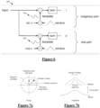
- the hardware 600 used to compute one term of X k ′ is illustrated in Figure 6 .
- the sine template 304 and cosine template 402 shown in Figure 4 are used in the circuit 600.
- detector 300 using the filter template 304 Figure 3 ) computes the imaginary part of the third term of the windowed DFT.
- references to the output of the detector 300 are to be understood as being the imaginary part of the third term of the windowed DFT, and this is important to an understanding of the following further refinements of the invention.
- Figure 7b shows a triangular window and a single lobed response, this is for simplicity of representation and is intended to represent the four lobed filter template 304 and the three lobed response 502, respectively.
- Exploring different time delay adjustments by sliding the offset or delay in the time domain ( Figure 7b ), rotates the coordinate system of the measurement ( Figure 7a ). When the evoked response phase aligns with the imaginary axis of Figure 7a , the output of the detector 300 is at its maximum.
- the output of the detector 300 is the projection of the (complex) evoked response onto the imaginary axis.
- the present embodiment further incorporates the third and fourth aspects of the invention, and recognises that the artifact 506 can be well modelled as being a sum of two exponentials, of differing time constant.
- phase of the DFT terms of a single exponential depend on the time constant of the exponential, as shown in Figure 8 for the filter template 304.
- the present embodiment recognises that the phase of each DFT term is unchanged by time delay.
- Figure 9 illustrates the filter output vector components arising from artefact only, when modelled as two exponentials.
- a 2 and B 2 are the two artifact phase vectors. These can be added using vector addition to produce the total artefact 902.
- the detector 300 will thus produce an output 904 which is the imaginary part of this vector; the projection of 902 onto the y-axis.
- the lengths of the two vectors reduce exponentially, but at different rates as the time constants are different, B2 decaying rapidly and A2 decaying slowly.
- the phases remain unchanged as per equation (8), resulting in the situation shown in Figure 9b .
- the total artefact vector is now 912, which due to the different relative contributions from each exponential component is of slightly changed phase to 902.
- the detector 3 00 will thus produce an output 914.
- Figures 10a and 10b illustrate, at respective times, the detector output vector components arising from artefact modelled as two exponentials and from an evoked response.
- V 1 and V 2 are the two artifact phase vectors
- CAP is the evoked response vector. These can be added using vector addition to produce the total artefact 1002.
- the detector 300 will thus produce an output 1004 which is the imaginary part of this vector; the projection of 1002 onto the y-axis.
- the lengths of the two artefact vectors have reduced exponentially, at different rates as the time constants are different, with V 2 decaying rapidly and V 1 decaying slowly.
- the time constant ⁇ 1 of the first (slow) exponential term is typically in the range 300 ⁇ s to 30 ms, more typically 500 ⁇ s to 3 ms and most commonly about 1 ms
- the time constant ⁇ 2 of the second (fast) exponential term is typically in the range 60 - 500 ⁇ s, more typically 100 - 300 ⁇ s, and most commonly about 150 ⁇ s.
- the method of this embodiment relies on making two complex measurements of the evoked response, at points in time separated by one quarter of a cycle, as shown in Figure 11a .
- the timing of the measurements is optimised in the manner described above in relation to Figure 7 , so that the first measurement (m I and m2) has a purely imaginary evoked response contribution (i.e. the evoked response aligns with the sin correlator 304), and the second measurement (m3 and m4) is purely real (i.e. aligns with the cosine 402). This leads to four measurements, m1 to m4.
- Figure 11b illustrates the locations of these four measurements m1 to m4 on the real and imaginary detector outputs.
- a difficulty in implementing this algorithm with measured data is that it measures two signals at once, namely the evoked response and the fast exponential, and each forms a noise source for the other.
- the phase of the evoked response is not known exactly, and this introduces errors into Figure 11b .
- the exponential estimation algorithm does not always find a solution, so the present embodiment further provides a second estimation method for these circumstances.
- This further estimation method recognises that the above algorithms can be extended by adding an additional correlation, to allow the phase of the evoked response to be calculated instead of being used as an input.
- an FFT will compute this faster than a DFT, especially if the FFT is factored to use the smallest number of multiply operations.
- a good choice of DFT length might be 16, factored as ( F 2 ⁇ F 2 ) ⁇ ( F 2 ⁇ F 2 ). For this factorization the twiddle factors between the F 2 operations are trivial, and so the only complex multiply required is in the middle.
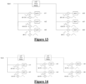
- Figure 14 illustrates an alternative embodiment utilising six measurement points.
- the evoked response in the spine (having three phases) takes approximately 1 ms.
- the evoked response will take around 30 samples. Consequently in such embodiments the filter template having four phases will comprise approximately 40 tap values, or data points.
- die length of the filter may comprise correspondingly greater or fewer filter taps.
- template is used to refer to a filter used via correlation to detect an ECAP.
- a template may be comprised of one or more wavelets or basis functions, or may be derived by some other method, and is configured to preferentially pass an ECAP but preferentially block or be orthogonal to artifact.
- Figure 15a illustrates sinusoidal binomial vectors in accordance with further embodiments of the invention.
- Figure 15b shows the generation of three-lobe, four-lobe and five-lobe templates.
- a notable property of the SBT is that its basis functions of the same length are orthogonal.
- the method used to generate the templates of Figure 15 up to five-lobes can be extended to a greater number of lobes.
- the window is not triangular for three or five lobed filter templates, but has a flat central portion in both cases, and in the case of five lobes the window having a piecewise linear rise and fall.
- the three lobed filter template window proposed by the present embodiments is not triangular but is a flat topped window, which has been found to significantly improve artefact rejection as compared to a triangular window of a three lobed filter template.
- SBT sinusoidal binomial transform
- Figure 16a illustrates the point values of a four lobed, 32 point filter template generated in accordance with the teachings of Figure 15 .
- Figure 16b illustrates the point values of a three lobed, 33 point filter template generated in accordance with the teachings of Figure 15 and in particular having a flat topped window.
- cosine templates of 3, 5 or more lobes can be similarly generated, noting the Figure 4 example for a four half cycles cosine template 402.
- the preceding embodiments further describe a filter template built using a triangular window.
- the triangular window is superior to the Bartlett, Hanning, rectangular and the Kaiser-Bessel for a variety of beta values.
- the performance of the four-lobe triangular template can be within 2dB of a matched filter for optimised offset.
- alternative embodiments may utilise windows other than the triangular window to useful effect, and such embodiments are thus within the scope of the present invention.
- some embodiments of the invention may use multiple identical templates, but shifted in time. Even though these are not orthogonal, a successive approximation method creatitig a compound template may provide better approximation. Additionally or alternatively, some embodiments may use templates that are a sum of templates of different frequencies, templates of different offset and/or templates of different numbers of lobes.
- a benefit of some embodiments of the present invention is that in some embodiments the detector produces an output based on a single neural measurement, without requiring multiple neural measurements to produce a detector output. Such embodiments may thus provide a swift response time of a feedback control loop utilising the detector output.
Landscapes
- Health & Medical Sciences (AREA)
- Life Sciences & Earth Sciences (AREA)
- Engineering & Computer Science (AREA)
- Animal Behavior & Ethology (AREA)
- Veterinary Medicine (AREA)
- Biomedical Technology (AREA)
- Public Health (AREA)
- General Health & Medical Sciences (AREA)
- Biophysics (AREA)
- Physics & Mathematics (AREA)
- Heart & Thoracic Surgery (AREA)
- Molecular Biology (AREA)
- Medical Informatics (AREA)
- Pathology (AREA)
- Surgery (AREA)
- Signal Processing (AREA)
- Physiology (AREA)
- Artificial Intelligence (AREA)
- Computer Vision & Pattern Recognition (AREA)
- Psychiatry (AREA)
- Neurology (AREA)
- Neurosurgery (AREA)
- Nuclear Medicine, Radiotherapy & Molecular Imaging (AREA)
- Radiology & Medical Imaging (AREA)
- Pain & Pain Management (AREA)
- Mathematical Physics (AREA)
- Measurement And Recording Of Electrical Phenomena And Electrical Characteristics Of The Living Body (AREA)
- Electrotherapy Devices (AREA)
Description
- The present invention relates to detection of a neural response, such as a neural response caused by a stimulus. In particular the present invention relates to detection of a compound action potential by using one or more electrodes implanted proximal to the neural pathway to obtain a neural measurement.
- Electrical neuromodulation is used or envisaged for use to treat a variety of disorders including chronic pain, Parkinson's disease, and migraine, and to restore function such as hearing and motor function. A neuromodulation system applies an electrical pulse to neural tissue in order to generate a therapeutic effect. Such a system typically comprises an implanted electrical pulse generator, and a power source such as a battery that may be rechargeable by transcutaneous inductive transfer. An electrode array is connected to the pulse generator, and is positioned close to the neural pathway(s) of interest. An electrical pulse applied to the neural pathway by an electrode causes the depolarisation of neurons, which generates propagating action potentials whether antidromic, orthodromic, or both, to achieve the therapeutic effect.
- When used to relieve chronic pain for example, the electrical pulse is applied to the dorsal column (DC) of the spinal cord and the electrode array is positioned in the dorsal epidural space. The dorsal column fibres being stimulated in this way inhibit the transmission of pain from that segment in the spinal cord to the brain.
- In general, the electrical stimulus generated in a neuromodulation system triggers a neural action potential which then has either an inhibitory or excitatory effect. Inhibitory effects can be used to modulate an undesired process such as the transmission of pain, or excitatory effects can be used to cause a desired effect such as the contraction of a muscle or stimulation of the auditory nerve.
- The action potentials generated among a large number of fibres sum to form a compound action potential (CAP). The CAP is the sum of responses from a large number of single fibre action potentials. When a CAP is electrically recorded, the measurement comprises the result of a large number of different fibres depolarising. The propagation velocity is determined largely by the fibre diameter and for large myelinated fibres as found in the dorsal root entry zone (DREZ) and nearby dorsal column the velocity can be over 60 ms-1. The CAP generated from the firing of a group of similar fibres is measured as a positive peak P1. in the recorded potential, then a negative peak N1, followed by a second positive peak P2. This is caused by the region of activation passing the recording electrode as the action potentials propagate along the individual fibres, producing the typical three-peaked response profile. Depending on stimulus polarity and the sense electrode configuration, the measured profile of some CAPs may be of reversed polarity, with two negative peaks and one positive peak.
- Approaches proposed for obtaining a neural measurement are described by the present applicant in International Patent Publication No.
WO 2012/155183 , and also byKing (US Patent No. 5,913,882 ),Nygard (US Patent No. 5,758,651 ) andDaly (US Patent Application No. 2007/0225767 ), for example, - To better understand the effects of neuromodulation and/or other neural stimuli, and for example to provide a stimulator controlled by neural response feedback, it is desirable to accurately detect a CAP resulting from the stimulus. Evoked responses are less difficult to detect when they appear later in time than the artifact, or when the signal-to-noise ratio is sufficiently high. The artifact is often restricted to a time of 1 - 2 ms after the stimulus and so, provided the neural response is detected after this time window, a response measurement can be more easily obtained. This is the case in surgical monitoring where there are large distances (e.g. more than 12 cm for nerves conducting at 60 m-1) between the stimulating and recording electrodes so that the propagation time from the stimulus site to the recording electrodes exceeds 2ms.
- However to characterize the responses from the dorsal columns, high stimulation currents and close proximity between electrodes are required, and therefore in such situations the measurement process must overcome artifact directly. However, this can be a difficult task as an observed CAP signal component in the neural measurement will typically have a maximum amplitude in the range of microvolts. In contrast a stimulus applied to evoke the CAP is typically several volts and results in electrode artifact, which manifests in the neural measurement as a decaying output of several millivolts partly or wholly contemporaneously with the CAP signal, presenting a significant obstacle to isolating or even detecting the much smaller CAP signal of interest.
- For example, to resolve a 10uV CAP with luV resolution in the presence of an input 5V stimulus, for example, requires an amplifier with a dynamic range of 134dB, which is impractical in implant systems. As the neural response can be contemporaneous with the stimulus and/or the stimulus artefact, CAP measurements present a difficult challenge of measurement amplifier design. In practice, many non-ideal aspects of a circuit lead to artefact, and as these mostly have a decaying exponential appearance that can be of positive or negative polarity, their identification and elimination can be laborious.
- The difficulty of this problem is further exacerbated when attempting to implement CAP detection in an implanted device. Typical implants have a power budget which permits a limited number, for example in the hundreds or low thousands, of processor instructions per stimulus, in order to maintain a desired battery lifetime. Accordingly, if a CAP detector for an implanted device is to be used regularly (e.g. once a second), then the detector should preferably consume only a small fraction of the power budget and thus desirably should require only in the tens of processor instructions in order to complete its task.
- Any discussion of documents, acts, materials, devices, articles or the like which has been included in the present specification is solely for the purpose of providing a context for the present invention. It is not to be taken as an admission that any or all of these matters form part of the prior art base or were common general knowledge in the field relevant to the present invention as it existed before the priority date of each claim of this application.
- Throughout this specification the word "comprise", or variations such as "comprises" or "comprising", will be understood to imply the inclusion of a stated element, integer or step, or group of elements, integers or steps, but not the exclusion of any other element, integer or step, or group of elements, integers or steps.
- In this specification, a statement that an element may be "at least one of" a list of options is to be understood that the element may be any one of the listed options, or may be any combination of two or more of the listed options.
- According to a first aspect the present invention provides a method according to claim 1.
- According to a second aspect the present invention provides an implantable device according to
claim 15. - The window may comprise a triangular window. The triangular window may be a standard triangular window of length Z, comprising coefficients w(n) as follows:
- For L odd:

- For L even:

- In preferred embodiments of the invention, the filter template comprises four half-cycles of an alternating waveform. Such embodiments recognise that a matched filter, comprising a three-peaked template shaped somewhat like the expected three-peaked CAP response, used to correlate against an obtained neural measurement, can optimise SNR when the noise is white, but that artefact is not while noise and that such three-peaked matched filters may perform less optimally in CAP detection in the presence of artifact.
- The filter template may comprise four half cycles of a sine wave, modified by being amplitude modulated by a triangular window, thus comprising four alternating peaks. Alternatively the filter template may comprise four half cycles of a cosine wave, modified by having an amplitude fitted within a triangular window, thus comprising five alternating peaks. Inverses of such filter templates, i.e. having opposite polarity, may be employed in some embodiments. The alternating waveform in alternative embodiments may be non-sinusoidal, but is preferably a continuous curve, and may in some embodiments resemble the profile of a neural response albeit comprising four half cycles.
- The present invention thus provides for selection of a filter template having improved artifact rejection. The present invention recognises that artifact can be reasonably accurately modelled as a sum of two exponentials having distinct time constants, and that because a Bartlett filter template window rejects the first three terms of a Taylor expansion of ex , namely the DC, linear, and quadratic terms, such embodiments of the present invention thus facilitate artifact rejection.
- Disclosed is furthermore a method for processing a neural measurement obtained in the presence of artifact, in order to detect whether a neural response is present in the neural measurement, the method comprising:
- obtaining a neural measurement from one or more sense electrodes;
- at a first time offset, correlating the neural measurement against a first filter template to produce a first measure m1 , the first filter template comprising an alternating waveform of a first phase;
- at the first time offset, correlating the neural measurement against a second filter template to produce a second measure m 2, the second filter template comprising an alternating waveform of a second phase 90 degrees offset to the first phase;
- at a second time offset, being at a non-integer multiple of 180 degrees offset from the first time offset, correlating the neural measurement against the first filter template to produce a third measure m3 ;
- at the second time offset, correlating the neural measurement against the second filter template to produce a fourth measure m4 ; and
- processing m1 to m4 to detect whether a neural response exists in the neural measurement.
- Disclosed is furthermore a device for processing a neural measurement obtained in the presence of artifact, in order to detect whether a neural response is present in the neural measurement, the device comprising:
- measurement circuitry for obtaining a neural measurement from one or more sense electrodes; and
- a processor configured to:
- at a first time offset, correlate the neural measurement against a first filter template to produce a first measure m1 , the first filter template comprising an alternating waveform of a first phase;
- at the first time offset, correlate the neural measurement against a second filter template to produce a second measure m2 , the second filter template comprising an alternating waveform of a second phase 90 degrees offset to the first phase;
- at a second time offset, being at a non-integer multiple of180 degrees offset from the first time offset, correlate the neural measurement against the first filter template to produce a third measure m3 ;
- at the second time offset, correlate the neural measurement against the second filter template to produce a fourth measure m4 ; and
- process m1 to m4 to detect whether a neural response exists in the neural measurement
- The first filter template may be anti-symmetric so as to create an imaginary DFT output, while the second filter template may be symmetric so as to create a real DFT output.
- The second time offset may be offset by 90 degrees, or 270 degrees, from the first time offset.
- The first and/or second filter template may each comprise four half cycles of an alternating waveform, amplitude modulated by a triangular window. For example the first filter template may comprise four half cycles of a sinusoid waveform amplitude modulated by a triangular window, and the second filter template may comprise four half cycles of a cosine waveform amplitude modulated by the triangular window. Alternatively, the alternating waveform of the first and second filter templates may be amplitude modulated by a Kaiser Bessel window, for example having β = 6.
- These disclosures are further advantageous when applied in relation to an implanted device, in that performing a correlation of a filter template with a neural measurement typically requires only in the tens of processor instructions, and thus consumes a suitably small fraction of the power budget of a typical implant, as compared for example to a double exponential matched filter approach which would require hundreds of processor instructions. It is preferred that only a single point of the correlation is calculated, at a predefined optimal time delay.
- Further provided is a method for efficiently determining an optimum time delay when a signal to artifact ratio is greater than one, at which a first or single point of the cross-correlation between the neural measurement and the filter template should be produced, the method comprising:
- at an approximate time delay between the neural response and the filter template, computing real and imaginary parts of the fundamental frequency of the DFT of the neural measurement,
- calculating a phase defined by the real and imaginary parts;
- relative to the fundamental frequency, calculating the time adjustment needed to change the calculated phase to pi/2; and
- defining the optimum time delay as being the sum of the approximate time delay and the time adjustment.
- Further provided is a method for efficiently determining an optimum time delay at which a first or single point of the cross-correlation between the neural measurement and the filter template should be produced, the method comprising:
- at the first time offset, correlating the neural measurement against a third filter template to produce a fifth measure m3 , the third filter template comprising an alternating waveform at double the frequency of the first filter template and of a third phase;
- at the second time offset, correlating the neural measurement against the third filter template to produce a sixth measure m6 ; and
- determining from m 5 and m6 a decay in artefact between the first time offset and the second time offset.
- The optimum time delay may then be used to define the single point at which the cross-correlation between the neural measurement and the filter template should be produced. The optimum time delay may be calculated regularly, for example prior to every attempted detection of a neural response, or occasionally, for example at one second intervals or in response to a detected change in the user's posture.
- The fundamental frequency may be the frequency of the three phases of the CAP and/or may be the frequency of the four cycles of the filter template.
- A length of the filter template is preferably selected so that the filter template comprises a number of filter points which, at a sampling rate at which the neural measurement is assessed, is four-thirds of the duration of a typical neural response.
- In preferred embodiments the measurement is obtained in accordance with the teachings of International Patent Publication No.
WO 2012/155183 , by the present applicant. In further preferred embodiments the detector output is used in a closed loop feedback circuit to control neuromodulation, for example in conjunction with the techniques of International Patent Publication No.WO 2012/155188 , by the present applicant. - The present invention thus recognises that the amplitude of an evoked response can be measured by calculating the dot product of a neural measurement and a filter template, provided that the filter template is substantially orthogonal with the artefact and has a dot-product with the response which is close to that of a matched filter matched to the evoked response. The filter template rejects DC, rejects first order signals (signals having a constant slope), and rejects low frequency signals which decay exponentially, such as artefact. The filter is preferably configured so as to be able to operate upon signals which occurred immediately after a stimulus.
- While four lobes provides the optimal trade-off between rejection of artifact and noise gain, alternative embodiments of the present invention may usefully employ a filter template comprising greater or fewer lobes. In such embodiments the filter template may comprise one or more basis functions derived from a sinusoidal binomial transform (SBT), for example, In embodiments comprising a three or five lobed filter template the window preferably comprises a flat central portion, as returned by the SBT, rather than a triangular peak for example, in order to better reject DC and ramp components of a Taylor expansion and thus better reject artifact. Some embodiments of the invention may use multiple identical filter template elements, but shifted in time. Even though these are not orthogonal, a successive approximation method creating a compound template may provide better approximation. Additionally or alternatively, some embodiments may use templates that are a sum of templates of different frequencies, templates of different offset and/or templates of different numbers of lobes.
- An example of the invention will now be described with reference to the accompanying drawings, in which:
-
Figure 1 illustrates an implantable device suitable for implementing the present invention; -
Figure 2 is a schematic of a feedback controller to effect stimulus control in response to recruitment; -
Figure 3a illustrates a neural response detector in accordance with one embodiment of the invention, andFigure 3b illustrates a modified version of the embodiment ofFigure 3a ; -
Figure 4 illustrates the amplitude profile of the filter template used in the detector ofFigure 3 ; and a cosine filter template, and the Bartlett window; -
Figure 5a illustrates the ability of the filter template to pass an evoked response, andFigure 5b illustrates the ability of the filter template to block artefact; -
Figure 6 illustrates hardware to compute a complex term of the windowed DFT; -
Figure 7 illustrates the effect of a clinical fitting procedure of the evoked response detector; -
Figure 8 illustrates the dependency of the phase of the DFT terms of an exponential on the time constant of the exponential; -
Figures 9a and 9b illustrate, at respective times, the detector output vector components arising from artefact only, when modelled as two exponentials; -
Figures 10a and 10b illustrate, at respective times, the detector output vector components arising from artefact modelled as two exponentials and from an evoked response; -
Figures 11a and 11b illustrate a four point measurement technique for measuring a CAP; -
Figure 12 illustrates exponential estimation and subtraction; -
Figure 13 illustrates a system for 6 point detection for when relative phase between evoked response and sampling window is unknown; -
Figure 14 illustrates an alternative embodiment for 6-point detection; -
Figures 15a and 15b illustrates generation of filter templates having three, four and five lobes, respectively; and -
Figures 16a and 16b respectively illustrate four and three lobed filter template point values, derived from the approach ofFigure 15 . -
Figure 1 illustrates animplantable device 100 suitable for implementing the present invention.Device 100 comprises an implantedcontrol unit 110, which controls application of neural stimuli, and controls a measurement process for obtaining a measurement of a neural response evoked by the stimuli from each of a plurality of electrodes. Thecontrol unit 110 includes a storage memory (or other storage device(s), not shown) for storing a lookup table that contains data defining a therapy map, setting out a relationship between applied stimuli regimes and the desired neural response .Device 100 further comprises anelectrode array 120 consisting of a three by eight array ofelectrodes 122, each of which may be selectively used as either the stimulus electrode or sense electrode, or both. -
Figure 2 is a schematic of a feedback controller implemented by thecontrol unit 110, based on recruitment. An important component of such feedback control is arecruitment estimator 210, which is tasked with the difficult operation of, in a simple form, detecting whether a neural response is present in a neural measurement output by the spinal cord potential (SCP) amplifier, or in a more complex form determining an amplitude of any such neural response. - The evoked CAP measurements in this embodiment are made by use of the neural response measurement techniques set out in International Patent Publication No.
WO2012/155183 . -
Figure 3a illustrates aneural response detector 300 in accordance with one embodiment of the invention. A digitised sampled form of the neural measurement obtained by the SCP amplifier is taken as theinput 302. Afilter template 304 is created at 306 by modulating asine wave 308 with aBartlett window 310. In alternative embodiments the template is likely to be predefined in this manner and simply retrieved from a memory or the like within control unit 1 10. A dot product of a suitable window of theneural measurement 302 and thefilter template 304 is calculated at 312, 314, to produce thedetector output 316, which is a single value scalar. Thedetector 300 may be modified as shown inFigure 3b by the addition of a gain term "a" for example to allow the correlator to produce approximately the same result as a peak-to-peak ECAP detector for comparison. -
Figure 4 illustrates the amplitude profile of thefilter template 304 used in thedetector 300 ofFigure 3 .Figure 4 further illustrates theBartlett window 310 used to amplitude modulate thesine wave 308. To assist in the following discussion,Figure 4 also shows anadditional filter template 402, comprising a cosine wave amplitude modulated by theBartlett window 310. It is noted on the x-axis ofFigure 4 that thefilter templates -
Figure 5a illustrates an evokedresponse 502 in the absence of artefact, the four-lobe filter template 304, and the sliding dot product or cross correlation thereof, 504. Again, it is noted that theresponse 502 comprises three lobes, whereas thefilter template 304 comprises four lobes and is four-thirds the expected length of theresponse 502. As can be seen in the slidingdot product 504, the evokedresponse 502 is substantially passed to the output of thedetector 300 by thefilter template 304, In contrastFigure 5b illustrates thecorrelation 508 of the fourlobe filter template 304 withpure artefact 506, illustrating that artefact is substantially blocked or heavily attenuated by thefilter template 304 and thus not passed to the output of thedetector 300. In this embodiment, the performance of the four-lobe filter template 304 at passing an expected neural response is within 2dB of that of a matched filter, but with significantly improved artifact rejection. - It is noted that when sampling at 10 kHz, for example, 20 samples will be obtained in a 2 ms window, so that to determine the entire cross correlation will require 400 multiply/add operations. Accordingly, rather than calculating the entire cross-correlation between a measured neural response and the filter template, the present embodiment further provides for calculation of only a single point of the correlation as the
output 316 ofdetector 300, as a single point requires only 20 samples when sampling a 2 ms window at 10 kHz. Noting that the arrival time of the neural response, or its position within theneural measurement 302, is not known a priori, it is necessary to determine an optimal time delay or offset between the neural measurement and the template filter, at which the single point of the correlation should then be calculated. The aim is to calculate the single point at the peak of thecurve 504, and no other. To this end, the present embodiment efficiently determines the optimal time delay, by noting the following. - The DFT is defined by:

- In equation (1), and in the rest of this document, frequency-domain signals are represented by capital letters, and time-domain signals using layer-case. When using the DFT for spectral analysis, it is usual to multiply the data by a window W(n) so this becomes:

- This can be expressed in traditional magnitude and phase terms where the magnitude of the windowed DFT term is


- The
hardware 600 used to compute one term of
Figure 6 . Notably, thesine template 304 andcosine template 402 shown inFigure 4 are used in thecircuit 600. Comparing this arrangement to the previous equation, for which the third term is:
detector 300 using the filter template 304 (Figure 3 ) computes the imaginary part of the third term of the windowed DFT. Thus, references to the output of thedetector 300 are to be understood as being the imaginary part of the third term of the windowed DFT, and this is important to an understanding of the following further refinements of the invention. - This also provides insight into what happens as the time delay is adjusted during a clinical fitting procedure, as shown in
Figure 7 . WhileFigure 7b shows a triangular window and a single lobed response, this is for simplicity of representation and is intended to represent the fourlobed filter template 304 and the threelobed response 502, respectively. Exploring different time delay adjustments by sliding the offset or delay in the time domain (Figure 7b ), rotates the coordinate system of the measurement (Figure 7a ). When the evoked response phase aligns with the imaginary axis ofFigure 7a , the output of thedetector 300 is at its maximum. This also presents a computationally efficient solution to the problem when at this phase, when the correlator output is maximum, the real part of the spectral component is zero, so its calculation can be avoided as depicted inFigure 3 , saving processor cycles. The output of thedetector 300 is the projection of the (complex) evoked response onto the imaginary axis. - When considering the entire cross correlation as the evoked response slides across the window (
Figure 7b ), the evoked response vector inFigure 7a rotates a full 360 degrees around the origin at least twice, and thus changes relatively quickly However as shown at the bottom ofFigure 7b , the amplitude of the convolution of the evoked response and the window changes relatively slowly. Accordingly, the present embodiment recognises that a swift technique to align the evoked response with the imaginary axis and thus find the peak in the correlator output is to: - 1. Roughly align the window and the signal S(t);
- 2. Calculate the imaginary (sin) and real (cosine) terms:
- a. I = S(t).W(t).sin(1KHz.2π.t), and
- b. Q = S(t). W(t).cos(1KHz.2πt);
- 3. Find the angle to the y-axis using atan(Q/I);
- 4. As the template has fixed known frequency, calculate the time shift needed to set the sin term to its maximum,
- 5. Calculate the imaginary (sin) and real (cosine) terms for the new delay. The cosine term should be much smaller than the sin term confirming that the method worked.
- Such embodiments may be particularly advantageous as compared to a clinical process requiring exploration of the varying delays in order to find a peak
- The present embodiment further incorporates the third and fourth aspects of the invention, and recognises that the
artifact 506 can be well modelled as being a sum of two exponentials, of differing time constant. Each exponential component has a voltage and a time value, leading to
- If


complex correlator 600 ofFigure 6 . - If we take some signal


- Thus, the phase of the DFT terms of a single exponential depend on the time constant of the exponential, as shown in
Figure 8 for thefilter template 304. However, the present embodiment recognises that the phase of each DFT term is unchanged by time delay. -
Figure 9 illustrates the filter output vector components arising from artefact only, when modelled as two exponentials. At a first time, shown inFigure 9a , A2 and B2 are the two artifact phase vectors. These can be added using vector addition to produce thetotal artefact 902. Thedetector 300 will thus produce anoutput 904 which is the imaginary part of this vector; the projection of 902 onto the y-axis. As time passes, the lengths of the two vectors reduce exponentially, but at different rates as the time constants are different, B2 decaying rapidly and A2 decaying slowly. However, the phases remain unchanged as per equation (8), resulting in the situation shown inFigure 9b . The total artefact vector is now 912, which due to the different relative contributions from each exponential component is of slightly changed phase to 902. Thedetector 3 00 will thus produce anoutput 914. -
Figures 10a and 10b illustrate, at respective times, the detector output vector components arising from artefact modelled as two exponentials and from an evoked response. At a first time t, shown inFigure 10 , V1 and V2 are the two artifact phase vectors, and CAP is the evoked response vector. These can be added using vector addition to produce thetotal artefact 1002. Thedetector 300 will thus produce anoutput 1004 which is the imaginary part of this vector; the projection of 1002 onto the y-axis. At a later time t+dt the lengths of the two artefact vectors have reduced exponentially, at different rates as the time constants are different, with V2 decaying rapidly and V1 decaying slowly. However, the phases remain unchanged as per equation (8), as shown inFigure 10b . In contrast, the amplitude of the evoked response vector CAP changes relatively slowly as discussed in relation toFigure 7b , but undergoes a change in phase as discussed in relation toFigure 7a , Thus, as shown inFigure 10b , the CAP vector rotates without undergoing a significant amplitude change. Thus, at one moment (Figure 10a ) the CAP vector can be orthogonal to V2, and at a later time (Figure 10b ) can be aligned with V2, - When modelling the artefact as a sum of two exponential terms, it has been determined from measurements of actual artefact that the time constant τ1 of the first (slow) exponential term is typically in the
range 300 µs to 30 ms, more typically 500 µs to 3 ms and most commonly about 1 ms, and that the time constant τ2 of the second (fast) exponential term is typically in the range 60 - 500 µs, more typically 100 - 300 µs, and most commonly about 150 µs. - The method of this embodiment, utilising the third and fourth aspects of the invention, relies on making two complex measurements of the evoked response, at points in time separated by one quarter of a cycle, as shown in
Figure 11a . The timing of the measurements is optimised in the manner described above in relation toFigure 7 , so that the first measurement (m I and m2) has a purely imaginary evoked response contribution (i.e. the evoked response aligns with the sin correlator 304), and the second measurement (m3 and m4) is purely real (i.e. aligns with the cosine 402). This leads to four measurements, m1 to m4. There are four unknowns - the magnitude of the artifact, the magnitude of the evoked response, the phase of the artifact and the time constant of the fast exponential. The slow exponential component of the artifact is well rejected by thefilter template 304 and thus can be omitted. It is known that the artifact contribution to the sin and cos correlators has a fixed ratio. Using simple algebra the unknowns can be eliminated. Therefore any CAP present in the neural measurement can be calculated as being:

-
Figure 11b illustrates the locations of these four measurements m1 to m4 on the real and imaginary detector outputs. - Knowing k also allows the evaluation of τ, and of the fast artifact exponential:

- To find the voltage of the fast exponential term for the artifact, one can further calculate the DFT of the exponential which is what would be expected from the detectors for an exponential input of that time constant, normalized to 1.0:

- Then, an estimation of the fast artifact term is:

- Having calculated the above, it is possible to improve the SAR of the signal by subtracting the estimated exponential, as shown in
Figure 12 . - A difficulty in implementing this algorithm with measured data is that it measures two signals at once, namely the evoked response and the fast exponential, and each forms a noise source for the other. Usually, the phase of the evoked response is not known exactly, and this introduces errors into
Figure 11b . When the evoked response is larger than the exponential, and the phase of the evoked response is not known, the exponential estimation algorithm does not always find a solution, so the present embodiment further provides a second estimation method for these circumstances. This further estimation method recognises that the above algorithms can be extended by adding an additional correlation, to allow the phase of the evoked response to be calculated instead of being used as an input. - When the relative phase (θ) of the evoked response to the sampling window is unknown, the proposal of
Figure 11 has 5 unknowns and 4 measurements, so the unknowns cannot be found. By adding two more DFT points this can be overcome, as shown inFigure 13 . These additional points (m5 and m6) are evaluated at a frequency equal to half the fundamental of the evoked response - to which the evoked response is orthogonal. Therefore these two additional points allow k to be evaluated:
- In turn, the five terms a,b,k,θ and c can be found. For some phase θ between the measurement window and the evoked response:


- The phase will change slowly, so once θ is known, it is possible to adjust the delay of the sampling window, and then revert to the four point algorithm of
Figure 11 . - When considering implementation of the six point technique of
Figure 13 , it is noted that in some embodiments an FFT will compute this faster than a DFT, especially if the FFT is factored to use the smallest number of multiply operations. A good choice of DFT length might be 16, factored as (F 2∘F 2)∘(F 2∘F 2). For this factorization the twiddle factors between the F 2 operations are trivial, and so the only complex multiply required is in the middle. -
Figure 14 illustrates an alternative embodiment utilising six measurement points. - It is further noted that running the calculation after the evoked response is finished allows the slow exponential to be measured.
- The evoked response in the spine (having three phases) takes approximately 1 ms. In embodiments employing a sample rate of 30KHz or a simple interval of 33us, the evoked response will take around 30 samples. Consequently in such embodiments the filter template having four phases will comprise approximately 40 tap values, or data points. In alternative embodiments, using an alternative sampling rate or measuring a faster or slower CAP, die length of the filter may comprise correspondingly greater or fewer filter taps.
- While the preceding embodiments have been described in relation to a filter template which comprises four half cycles, alternative embodiments of the present invention may nevertheless usefully employ a filter template comprising greater or fewer lobes. The present invention thus recognises that the ideal number if lobes is four. This is in contrast to a two lobe filter, which will have equal first and second lobes and will thus put more emphasis on the early parts of the signal where the signal-to-artifact is worse. Further, a filter with an odd number of lobes does not tend to have good artifact rejection properties. Moreover, if one were to use a six-lobe filter, or higher even-number lobed filter, the window becomes too wide relative to the 3-lobed neural response, and at least half the correlation time would just be looking at noise. Since most of the problematic artifact is in the first two lobes, a 6 lobe filter will tend not to provide better artifact rejection than the four-lobe filter. Four lobes thus provides the optimal trade-off between rejection of artifact and noise gain.
- Nevertheless, alternative embodiments of the present invention may usefully employ a filter template comprising greater or fewer lobes. We now describe the mathematical properties of templates of other embodiments of the invention. The term "template" is used to refer to a filter used via correlation to detect an ECAP. A template may be comprised of one or more wavelets or basis functions, or may be derived by some other method, and is configured to preferentially pass an ECAP but preferentially block or be orthogonal to artifact.
Figure 15a illustrates sinusoidal binomial vectors in accordance with further embodiments of the invention.Figure 15b shows the generation of three-lobe, four-lobe and five-lobe templates. A notable property of the SBT is that its basis functions of the same length are orthogonal. It is to be appreciated that the method used to generate the templates ofFigure 15 up to five-lobes can be extended to a greater number of lobes. It is further noted that the window is not triangular for three or five lobed filter templates, but has a flat central portion in both cases, and in the case of five lobes the window having a piecewise linear rise and fall. Thus, the three lobed filter template window proposed by the present embodiments is not triangular but is a flat topped window, which has been found to significantly improve artefact rejection as compared to a triangular window of a three lobed filter template. - That is, an important property of the sinusoidal binomial transform (SBT) is its ability to reject polynomial signals. If an SBT template of order n is used, it will reject all the terms of the Taylor series up to order n.
-
Figure 16a illustrates the point values of a four lobed, 32 point filter template generated in accordance with the teachings ofFigure 15 .Figure 16b illustrates the point values of a three lobed, 33 point filter template generated in accordance with the teachings ofFigure 15 and in particular having a flat topped window. - It is further to be appreciated that cosine templates of 3, 5 or more lobes can be similarly generated, noting the
Figure 4 example for a four halfcycles cosine template 402. - The preceding embodiments further describe a filter template built using a triangular window. The triangular window is superior to the Bartlett, Hanning, rectangular and the Kaiser-Bessel for a variety of beta values. The performance of the four-lobe triangular template can be within 2dB of a matched filter for optimised offset. Nevertheless, alternative embodiments may utilise windows other than the triangular window to useful effect, and such embodiments are thus within the scope of the present invention.
- Moreover, while the described embodiments use a single term of the SBT for response detection, the present invention further recognises that there are possible extensions to this method Therefore, some embodiments of the invention may use multiple identical templates, but shifted in time. Even though these are not orthogonal, a successive approximation method creatitig a compound template may provide better approximation. Additionally or alternatively, some embodiments may use templates that are a sum of templates of different frequencies, templates of different offset and/or templates of different numbers of lobes.
- A benefit of some embodiments of the present invention is that in some embodiments the detector produces an output based on a single neural measurement, without requiring multiple neural measurements to produce a detector output. Such embodiments may thus provide a swift response time of a feedback control loop utilising the detector output.
Claims (15)
- A method for processing a neural measurement obtained in the presence of artefact, in order to detect whether a neural response is present in the neural measurement, the method comprising:obtaining by an implanted device, a neural measurement from one or more sense electrodes, the neural measurement being obtained in the presence of artefact;the implanted device correlating the neural measurement against a filter template, the filter template comprising at least three half cycles of an alternating waveform, amplitude modulated by a window, wherein the filter template rejects DC, rejects first order signals, and rejects low frequency signals which decay exponentially; andthe implanted device determining from an output of the correlating whether a neural response is present in the neural measurement.
- The method of claim 1 wherein the window comprises a triangular window.
- The method of claim 2 wherein the triangular window is a standard triangular window of length L comprising coefficients w(n) as follows:For L odd:
 For L even:
- The method of claim 2 wherein the triangular window is a Bartlett window in which samples 1 and L are zero.
- The method of claim 1 wherein the window comprises one of a Hanning window, a rectangular window or a Kaiser-Bessel window.
- The method of claim 1 wherein the window comprises one or more basis functions derived from a sinusoidal binomial transform.
- The method of any one of claims 1 to 6 wherein the filter template comprises four halfcycles of an alternating waveform.
- The method of any one of claims 1 to 7 wherein the filter template comprises half cycles of a sine wave, modified by being amplitude modulated by the window.
- The method of any one of claims 1 to 7 wherein the filter template comprises half cycles of a cosine wave, modified by being amplitude modulated by the window.
- The method of any one of claims 1 to 9 wherein only a single point of the correlation is calculated.
- The method of claim 10 wherein the single point of the correlation is calculated at a predefined optimal time delay.
- The method of claim 11, further comprising determining the optimum time delay when a signal to artefact ratio is greater than one, at which a first or single point of the cross-correlation between the neural measurement and the filter template should be produced, by:at an approximate time delay between the neural response and the filter template, computing real and imaginary parts of the fundamental frequency of the DFT of the neural measurement;calculating a phase defined by the real and imaginary parts;relative to a fundamental frequency of the template, calculating the time adjustment needed to change the calculated phase to π/2; anddefining the optimum time delay as being the sum of the approximate time delay and the time adjustment.
- The method of claim 11 or claim 12, wherein the optimum time delay is recalculated prior to every attempted detection of a neural response.
- The method of claim 11 or claim 12, wherein the optimum time delay is recalculated in response to a detected change in the user's posture.
- An implantable device for processing a neural measurement obtained in the presence of artefact, in order to detect whether a neural response is present in the neural measurement, the device comprising:measurement circuitry for obtaining a neural measurement from one or more sense electrodes; anda processor configured to correlate the neural measurement against a filter template, the filter template comprising at least three half cycles of an alternating waveform, amplitude modulated by a window, wherein the filter template rejects DC, rejects first order signals, and rejects low frequency signals which decay exponentially; and the processor further configured to determine from an output of the correlating whether a neural response is present in the neural measurement.
Applications Claiming Priority (2)
| Application Number | Priority Date | Filing Date | Title |
|---|---|---|---|
| AU2013904519A AU2013904519A0 (en) | 2013-11-22 | Method and Device for Detecting a Neural Response in a Neural Measurement | |
| PCT/AU2014/050369 WO2015074121A1 (en) | 2013-11-22 | 2014-11-22 | Method and device for detecting a neural response in a neural measurement |
Publications (4)
| Publication Number | Publication Date |
|---|---|
| EP3071100A1 EP3071100A1 (en) | 2016-09-28 |
| EP3071100A4 EP3071100A4 (en) | 2017-07-12 |
| EP3071100C0 EP3071100C0 (en) | 2024-01-03 |
| EP3071100B1 true EP3071100B1 (en) | 2024-01-03 |
Family
ID=53178729
Family Applications (1)
| Application Number | Title | Priority Date | Filing Date |
|---|---|---|---|
| EP14863597.2A Active EP3071100B1 (en) | 2013-11-22 | 2014-11-22 | Method and device for detecting a neural response in a neural measurement |
Country Status (7)
| Country | Link |
|---|---|
| US (5) | US10426409B2 (en) |
| EP (1) | EP3071100B1 (en) |
| JP (1) | JP6671021B2 (en) |
| CN (2) | CN110623637B (en) |
| AU (1) | AU2014353891B2 (en) |
| CA (1) | CA2929874C (en) |
| WO (1) | WO2015074121A1 (en) |
Families Citing this family (58)
| Publication number | Priority date | Publication date | Assignee | Title |
|---|---|---|---|---|
| US9089267B2 (en) | 2010-06-18 | 2015-07-28 | Cardiac Pacemakers, Inc. | Methods and apparatus for adjusting neurostimulation intensity using evoked responses |
| WO2012155185A1 (en) | 2011-05-13 | 2012-11-22 | National Ict Australia Ltd | Method and apparatus for measurement of neural response |
| WO2012155189A1 (en) | 2011-05-13 | 2012-11-22 | National Ict Australia Ltd | Method and apparatus for estimating neural recruitment - f |
| ES2694156T3 (en) | 2011-05-13 | 2018-12-18 | Saluda Medical Pty Limited | Apparatus for the measurement of the neural response |
| US9872990B2 (en) | 2011-05-13 | 2018-01-23 | Saluda Medical Pty Limited | Method and apparatus for application of a neural stimulus |
| US20140236042A1 (en) | 2011-05-13 | 2014-08-21 | Saluda Medical Pty. Ltd. | Method and apparatus for measurement of neural response |
| DK2908905T3 (en) | 2012-11-06 | 2020-12-14 | Saluda Medical Pty Ltd | SYSTEM FOR CONTROLLING ELECTRICAL CONDITIONS IN TISSUE |
| AU2013344311B2 (en) | 2012-11-06 | 2017-11-30 | Saluda Medical Pty Ltd | Method and system for controlling electrical conditions of tissue |
| CA2929971C (en) | 2013-11-15 | 2023-03-07 | Saluda Medical Pty Ltd | Monitoring brain neural potentials |
| JP6671021B2 (en) | 2013-11-22 | 2020-03-25 | サルーダ・メディカル・ピーティーワイ・リミテッド | Method and device for detecting a neural response in a neural measurement |
| EP3122247B1 (en) | 2014-03-28 | 2025-05-07 | Saluda Medical Pty Ltd | Assessing neural state from action potentials |
| CA2944042C (en) | 2014-05-05 | 2023-08-29 | Saluda Medical Pty Ltd | Improved neural measurement |
| CN106714896B (en) | 2014-07-25 | 2020-04-21 | 萨鲁达医疗有限公司 | Nerve stimulation dosing |
| US11006846B2 (en) | 2014-11-17 | 2021-05-18 | Saluda Medical Pty Ltd | Method and device for detecting a neural response in neural measurements |
| AU2015362075B2 (en) | 2014-12-11 | 2021-03-11 | Saluda Medical Pty Ltd | Implantable electrode positioning |
| EP3218046B1 (en) | 2014-12-11 | 2024-04-17 | Saluda Medical Pty Ltd | Device and computer program for feedback control of neural stimulation |
| WO2016115596A1 (en) | 2015-01-19 | 2016-07-28 | Saluda Medical Pty Ltd | Method and device for neural implant communication |
| CN107530543B (en) | 2015-04-09 | 2021-03-02 | 萨鲁达医疗有限公司 | Electrode-to-nerve distance estimation |
| ES2989752T3 (en) | 2015-05-31 | 2024-11-27 | Closed Loop Medical Pty Ltd | Adjustment of brain neurostimulator electrodes |
| JP2018516150A (en) | 2015-05-31 | 2018-06-21 | サルーダ・メディカル・ピーティーワイ・リミテッド | Cranial nerve activity monitoring |
| CA2980482C (en) | 2015-06-01 | 2023-09-26 | Saluda Medical Pty Ltd | Motor fibre neuromodulation |
| US11191966B2 (en) | 2016-04-05 | 2021-12-07 | Saluda Medical Pty Ltd | Feedback control of neuromodulation |
| US10406368B2 (en) | 2016-04-19 | 2019-09-10 | Boston Scientific Neuromodulation Corporation | Pulse generator system for promoting desynchronized firing of recruited neural populations |
| CN109561849B (en) * | 2016-06-24 | 2023-01-13 | 萨鲁达医疗有限公司 | Artifact reduced neural stimulation |
| US11612751B2 (en) | 2017-08-11 | 2023-03-28 | Boston Scientific Neuromodulation Corporation | Stimulation configuration variation to control evoked temporal patterns |
| US11129987B2 (en) | 2017-10-04 | 2021-09-28 | Boston Scientific Neuromodulation Corporation | Adjustment of stimulation in a stimulator using detected evoked compound action potentials |
| AU2019205211B2 (en) | 2018-01-08 | 2021-08-05 | Boston Scientific Neuromodulation Corporation | Automatic adjustment of sub-perception therapy in an implantable stimulator using detected compound action potentials |
| WO2019157559A1 (en) | 2018-02-15 | 2019-08-22 | Saluda Medical Pty Limited | Power efficient stimulators |
| US20190275331A1 (en) | 2018-03-12 | 2019-09-12 | Boston Scientific Neuromodulation Corporation | Neural Stimulation with Decomposition of Evoked Compound Action Potentials |
| US10974042B2 (en) | 2018-03-26 | 2021-04-13 | Boston Scientific Neuromodulation Corporation | System and methods for heart rate and electrocardiogram extraction from a spinal cord stimulation system |
| US11040202B2 (en) | 2018-03-30 | 2021-06-22 | Boston Scientific Neuromodulation Corporation | Circuitry to assist with neural sensing in an implantable stimulator device |
| CA3098468A1 (en) | 2018-04-27 | 2019-10-31 | Saluda Medical Pty Ltd | Neurostimulation of mixed nerves |
| US11241580B2 (en) * | 2018-06-01 | 2022-02-08 | Boston Scientific Neuromodulation Corporation | Artifact reduction in a sensed neural response |
| JP7387650B2 (en) | 2018-06-21 | 2023-11-28 | メドトロニック,インコーポレイテッド | Control of electrical stimulation therapy by ECAP |
| JP7344231B2 (en) * | 2018-06-21 | 2023-09-13 | メドトロニック,インコーポレイテッド | Control of electrical stimulation therapy by ECAP |
| CA3123328A1 (en) * | 2018-12-17 | 2020-06-25 | Saluda Medical Pty Ltd | Improved detection of action potentials |
| EP4218902B1 (en) | 2019-03-29 | 2024-08-14 | Boston Scientific Neuromodulation Corporation | Circuitry to assist with neural sensing in an implantable stimulator device in the presence of stimulation artifacts |
| EP3897822B1 (en) | 2019-03-29 | 2024-08-14 | Boston Scientific Neuromodulation Corporation | Neural sensing in an implantable stimulator device during the provision of active stimulation |
| US11504526B2 (en) | 2019-05-30 | 2022-11-22 | Boston Scientific Neuromodulation Corporation | Methods and systems for discrete measurement of electrical characteristics |
| WO2020257705A1 (en) | 2019-06-20 | 2020-12-24 | Boston Scientific Neuromodulation Corporation | Methods and systems for interleaving waveforms for electrical stimulation and measurement |
| JP7595639B2 (en) * | 2019-07-12 | 2024-12-06 | サルーダ・メディカル・ピーティーワイ・リミテッド | SYSTEM, METHOD, AND NON-TRANSITORY COMPUTER READABLE MEDIUM FOR AUTOMATED ASSESSMENT OF NEURAL RESPONSE RECORDINGS - Patent application |
| WO2021021659A1 (en) | 2019-07-26 | 2021-02-04 | Boston Scientific Neuromodulation Corporation | Methods and systems for storage, retrieval, and visualization of signals and signal features |
| CN114025833B (en) | 2019-07-26 | 2025-02-14 | 波士顿科学神经调制公司 | Methods and systems for electrical stimulation adjustment based on patient-specific factors |
| CN114555178B (en) | 2019-08-06 | 2025-05-16 | 波士顿科学神经调制公司 | Neural sensing in implantable stimulator devices during passive charge recovery |
| AU2020369847B2 (en) | 2019-10-21 | 2024-01-11 | Boston Scientific Neuromodulation Corporation | Assessment and adjustment of time-varying pulse patterns in a spinal cord stimulator system |
| US11547855B2 (en) | 2019-10-25 | 2023-01-10 | Medtronic, Inc. | ECAP sensing for high frequency neurostimulation |
| US11931582B2 (en) | 2019-10-25 | 2024-03-19 | Medtronic, Inc. | Managing transient overstimulation based on ECAPs |
| US12128235B2 (en) | 2020-03-06 | 2024-10-29 | Medtronic, Inc. | Controlling electrical stimulation based on a sensed stimulation signal |
| TWI740593B (en) * | 2020-03-16 | 2021-09-21 | 醫博科技股份有限公司 | Posture adjustment system |
| US12097373B2 (en) | 2020-06-10 | 2024-09-24 | Medtronic, Inc. | Control policy settings for electrical stimulation therapy |
| US11857793B2 (en) | 2020-06-10 | 2024-01-02 | Medtronic, Inc. | Managing storage of sensed information |
| US11707626B2 (en) | 2020-09-02 | 2023-07-25 | Medtronic, Inc. | Analyzing ECAP signals |
| US11896828B2 (en) | 2020-10-30 | 2024-02-13 | Medtronic, Inc. | Implantable lead location using ECAP |
| CN117062649A (en) * | 2021-02-09 | 2023-11-14 | 萨鲁达医疗有限公司 | Intra-stimulus recruitment control |
| US12329971B2 (en) | 2021-07-16 | 2025-06-17 | Saluda Medical Pty Ltd | Adaptation of neurostimulation therapy to age-related physiological changes |
| US12208269B2 (en) | 2022-03-14 | 2025-01-28 | Medtronic, Inc. | Calibration for ECAP sensing |
| AU2023350708A1 (en) * | 2022-10-01 | 2025-04-03 | Saluda Medical Pty Limited | Improved measurement of evoked neural response characteristics |
| WO2025015371A1 (en) * | 2023-07-14 | 2025-01-23 | Saluda Medical Pty Ltd | Improved analysis of mixed electrophysiological responses to neural stimulation |
Family Cites Families (359)
| Publication number | Priority date | Publication date | Assignee | Title |
|---|---|---|---|---|
| US3724467A (en) | 1971-04-23 | 1973-04-03 | Avery Labor Inc | Electrode implant for the neuro-stimulation of the spinal cord |
| US3736434A (en) | 1971-06-07 | 1973-05-29 | Westinghouse Air Brake Co | Fail-safe electronic comparator circuit |
| US3817254A (en) | 1972-05-08 | 1974-06-18 | Medtronic Inc | Transcutaneous stimulator and stimulation method |
| US3898472A (en) | 1973-10-23 | 1975-08-05 | Fairchild Camera Instr Co | Occupancy detector apparatus for automotive safety system |
| US4158196A (en) | 1977-04-11 | 1979-06-12 | Crawford George E Jr | Man-machine interface system |
| FR2419720A1 (en) | 1978-03-14 | 1979-10-12 | Cardiofrance Co | IMPLANTABLE HEART STIMULATOR WITH THERAPEUTIC AND DIAGNOSTIC FUNCTIONS |
| US4474186A (en) | 1979-07-17 | 1984-10-02 | Georgetown University | Computerized electro-oculographic (CEOG) system with feedback control of stimuli |
| US4807643A (en) | 1982-08-16 | 1989-02-28 | University Of Iowa Research Foundation | Digital electroneurometer |
| US4628934A (en) | 1984-08-07 | 1986-12-16 | Cordis Corporation | Method and means of electrode selection for pacemaker with multielectrode leads |
| CA1279101C (en) | 1985-10-10 | 1991-01-15 | Christopher Van Den Honert | Multichannel electrical stimulator with improved channel isolation |
| US4817628A (en) | 1985-10-18 | 1989-04-04 | David L. Zealear | System and method for evaluating neurological function controlling muscular movements |
| DE3831809A1 (en) | 1988-09-19 | 1990-03-22 | Funke Hermann | DEVICE DETERMINED AT LEAST PARTLY IN THE LIVING BODY |
| US5143081A (en) | 1990-07-27 | 1992-09-01 | New York University | Randomized double pulse stimulus and paired event analysis |
| US5172690A (en) | 1990-10-26 | 1992-12-22 | Telectronics Pacing Systems, Inc. | Automatic stimulus artifact reduction for accurate analysis of the heart's stimulated response |
| US5139020A (en) | 1991-03-08 | 1992-08-18 | Telectronics Pacing Systems, Inc. | Method and apparatus for controlling the hemodynamic state of a patient based on systolic time interval measurements detecting using doppler ultrasound techniques |
| US5184615A (en) | 1991-03-08 | 1993-02-09 | Telectronics Pacing Systems, Inc. | Apparatus and method for detecting abnormal cardiac rhythms using evoked potential measurements in an arrhythmia control system |
| US5156154A (en) | 1991-03-08 | 1992-10-20 | Telectronics Pacing Systems, Inc. | Monitoring the hemodynamic state of a patient from measurements of myocardial contractility using doppler ultrasound techniques |
| US5188106A (en) | 1991-03-08 | 1993-02-23 | Telectronics Pacing Systems, Inc. | Method and apparatus for chronically monitoring the hemodynamic state of a patient using doppler ultrasound |
| US5215100A (en) | 1991-04-29 | 1993-06-01 | Occupational Preventive Diagnostic, Inc. | Nerve condition monitoring system and electrode supporting structure |
| AU656163B2 (en) | 1991-07-15 | 1995-01-27 | Medtronic, Inc. | Medical stimulator with operational amplifier output circuit |
| US5324311A (en) | 1992-09-04 | 1994-06-28 | Siemens Pacesetter, Inc. | Coaxial bipolar connector assembly for implantable medical device |
| US5497781A (en) | 1992-10-30 | 1996-03-12 | Chen; Yunquan | Recording biological signals using Hilbert transforms |
| DE69328194T2 (en) | 1992-12-22 | 2000-09-21 | Cochlear Pty Ltd | DEVICE AND SYSTEM FOR TELEMETRY |
| GB9302335D0 (en) | 1993-02-05 | 1993-03-24 | Macdonald Alexander J R | Electrotherapeutic apparatus |
| US5417719A (en) | 1993-08-25 | 1995-05-23 | Medtronic, Inc. | Method of using a spinal cord stimulation lead |
| US5431693A (en) | 1993-12-10 | 1995-07-11 | Intermedics, Inc. | Method of verifying capture of the heart by a pacemaker |
| US5476486A (en) | 1994-03-04 | 1995-12-19 | Telectronics Pacing Systems, Inc. | Automatic atrial pacing pulse threshold determination utilizing an external programmer and a V-sense electrode |
| US5458623A (en) | 1994-03-04 | 1995-10-17 | Telectronics Pacing Systems, Inc. | Automatic atrial pacing threshold determination utilizing an external programmer and a surface electrogram |
| JP2596372B2 (en) | 1994-04-21 | 1997-04-02 | 日本電気株式会社 | Evoked potential measurement device |
| AUPM883794A0 (en) | 1994-10-17 | 1994-11-10 | University Of Melbourne, The | Multiple pulse stimulation |
| US5785651A (en) | 1995-06-07 | 1998-07-28 | Keravision, Inc. | Distance measuring confocal microscope |
| US6463328B1 (en) | 1996-02-02 | 2002-10-08 | Michael Sasha John | Adaptive brain stimulation method and system |
| US6066163A (en) | 1996-02-02 | 2000-05-23 | John; Michael Sasha | Adaptive brain stimulation method and system |
| FR2796562B1 (en) | 1996-04-04 | 2005-06-24 | Medtronic Inc | TECHNIQUES FOR STIMULATING LIVING TISSUE AND RECORDING WITH LOCAL CONTROL OF ACTIVE SITES |
| US5702429A (en) | 1996-04-04 | 1997-12-30 | Medtronic, Inc. | Neural stimulation techniques with feedback |
| WO1997037720A1 (en) | 1996-04-04 | 1997-10-16 | Medtronic, Inc. | Living tissue stimulation and recording techniques |
| US6493576B1 (en) | 1996-06-17 | 2002-12-10 | Erich Jaeger Gmbh | Method and apparatus for measuring stimulus-evoked potentials of the brain |
| WO1997048447A1 (en) | 1996-06-20 | 1997-12-24 | Advanced Bionics Corporation | Self-adjusting cochlear implant system and method for fitting same |
| US6246912B1 (en) | 1996-06-27 | 2001-06-12 | Sherwood Services Ag | Modulated high frequency tissue modification |
| US5792212A (en) | 1997-03-07 | 1998-08-11 | Medtronic, Inc. | Nerve evoked potential measurement system using chaotic sequences for noise rejection |
| US5895416A (en) | 1997-03-12 | 1999-04-20 | Medtronic, Inc. | Method and apparatus for controlling and steering an electric field |
| US5873898A (en) | 1997-04-29 | 1999-02-23 | Medtronic, Inc. | Microprocessor capture detection circuit and method |
| US7628761B2 (en) * | 1997-07-01 | 2009-12-08 | Neurometrix, Inc. | Apparatus and method for performing nerve conduction studies with localization of evoked responses |
| US5999848A (en) | 1997-09-12 | 1999-12-07 | Alfred E. Mann Foundation | Daisy chainable sensors and stimulators for implantation in living tissue |
| US6522932B1 (en) | 1998-02-10 | 2003-02-18 | Advanced Bionics Corporation | Implantable, expandable, multicontact electrodes and tools for use therewith |
| CA2223668C (en) | 1998-02-23 | 2000-07-11 | James Stanley Podger | The strengthened quad antenna structure |
| US6421566B1 (en) | 1998-04-30 | 2002-07-16 | Medtronic, Inc. | Selective dorsal column stimulation in SCS, using conditioning pulses |
| US6027456A (en) | 1998-07-10 | 2000-02-22 | Advanced Neuromodulation Systems, Inc. | Apparatus and method for positioning spinal cord stimulation leads |
| US7277758B2 (en) | 1998-08-05 | 2007-10-02 | Neurovista Corporation | Methods and systems for predicting future symptomatology in a patient suffering from a neurological or psychiatric disorder |
| US7231254B2 (en) | 1998-08-05 | 2007-06-12 | Bioneuronics Corporation | Closed-loop feedback-driven neuromodulation |
| US6212431B1 (en) | 1998-09-08 | 2001-04-03 | Advanced Bionics Corporation | Power transfer circuit for implanted devices |
| US20060217782A1 (en) | 1998-10-26 | 2006-09-28 | Boveja Birinder R | Method and system for cortical stimulation to provide adjunct (ADD-ON) therapy for stroke, tinnitus and other medical disorders using implantable and external components |
| US6253109B1 (en) | 1998-11-05 | 2001-06-26 | Medtronic Inc. | System for optimized brain stimulation |
| US6114164A (en) | 1998-12-07 | 2000-09-05 | The Regents Of The University Of Michigan | System and method for emulating an in vivo environment of a muscle tissue specimen |
| US6898582B2 (en) | 1998-12-30 | 2005-05-24 | Algodyne, Ltd. | Method and apparatus for extracting low SNR transient signals from noise |
| US6909917B2 (en) | 1999-01-07 | 2005-06-21 | Advanced Bionics Corporation | Implantable generator having current steering means |
| ES2358189T3 (en) | 1999-07-21 | 2011-05-06 | Med-El Elektromedizinische Geräte GmbH | COCLEAR IMPLANT OF MULTIPLE CHANNELS WITH TELEMETRY OF THE NEURONAL RESPONSE. |
| US6516227B1 (en) | 1999-07-27 | 2003-02-04 | Advanced Bionics Corporation | Rechargeable spinal cord stimulator system |
| US6381496B1 (en) | 1999-10-01 | 2002-04-30 | Advanced Bionics Corporation | Parameter context switching for an implanted device |
| EP1244496A1 (en) | 1999-12-17 | 2002-10-02 | Advanced Bionics Corporation | Magnitude programming for implantable electrical stimulator |
| US6473649B1 (en) | 1999-12-22 | 2002-10-29 | Cardiac Pacemakers, Inc. | Rate management during automatic capture verification |
| US20020055688A1 (en) | 2000-05-18 | 2002-05-09 | Jefferson Jacob Katims | Nervous tissue stimulation device and method |
| AU2001268473A1 (en) | 2000-06-20 | 2002-01-02 | Advanced Bionics Corporation | Apparatus for treatment of mood and/or anxiety disorders by electrical brain stimulation and/or drug infusion |
| US7305268B2 (en) | 2000-07-13 | 2007-12-04 | Northstar Neurscience, Inc. | Systems and methods for automatically optimizing stimulus parameters and electrode configurations for neuro-stimulators |
| US7831305B2 (en) | 2001-10-15 | 2010-11-09 | Advanced Neuromodulation Systems, Inc. | Neural stimulation system and method responsive to collateral neural activity |
| AU2001237911A1 (en) | 2000-10-30 | 2002-05-21 | Neuropace, Inc. | System and method for determining stimulation parameters for the treatment of epileptic seizures |
| US7089059B1 (en) | 2000-11-03 | 2006-08-08 | Pless Benjamin D | Predicting susceptibility to neurological dysfunction based on measured neural electrophysiology |
| WO2002043623A1 (en) | 2000-11-29 | 2002-06-06 | Cochlear Limited | Pre-curved cochlear implant electrode array |
| US6594524B2 (en) * | 2000-12-12 | 2003-07-15 | The Trustees Of The University Of Pennsylvania | Adaptive method and apparatus for forecasting and controlling neurological disturbances under a multi-level control |
| US6600954B2 (en) | 2001-01-25 | 2003-07-29 | Biocontrol Medical Bcm Ltd. | Method and apparatus for selective control of nerve fibers |
| US8060208B2 (en) | 2001-02-20 | 2011-11-15 | Case Western Reserve University | Action potential conduction prevention |
| WO2002082982A1 (en) | 2001-04-18 | 2002-10-24 | Cochlear Limited | Method and apparatus for measurement of evoked neural response |
| US6658293B2 (en) | 2001-04-27 | 2003-12-02 | Medtronic, Inc. | Method and system for atrial capture detection based on far-field R-wave sensing |
| US6816744B2 (en) | 2001-05-29 | 2004-11-09 | Reproductive Health Technologies, Inc. | Device and system for remote for in-clinic trans-abdominal/vaginal/cervical acquisition, and detection, analysis, and communication of maternal uterine and maternal and fetal cardiac and fetal brain activity from electrical signals |
| US6936012B2 (en) | 2001-06-18 | 2005-08-30 | Neurometrix, Inc. | Method and apparatus for identifying constituent signal components from a plurality of evoked physiological composite signals |
| ES2329452T3 (en) | 2001-07-11 | 2009-11-26 | Cns Response, Inc. | PROCEDURE TO PREACH THE RESULT OF TREATMENTS. |
| US6449512B1 (en) | 2001-08-29 | 2002-09-10 | Birinder R. Boveja | Apparatus and method for treatment of urological disorders using programmerless implantable pulse generator system |
| US7778711B2 (en) | 2001-08-31 | 2010-08-17 | Bio Control Medical (B.C.M.) Ltd. | Reduction of heart rate variability by parasympathetic stimulation |
| US7778703B2 (en) | 2001-08-31 | 2010-08-17 | Bio Control Medical (B.C.M.) Ltd. | Selective nerve fiber stimulation for treating heart conditions |
| US20140046407A1 (en) | 2001-08-31 | 2014-02-13 | Bio Control Medical (B.C.M.) Ltd. | Nerve stimulation techniques |
| US8571653B2 (en) | 2001-08-31 | 2013-10-29 | Bio Control Medical (B.C.M.) Ltd. | Nerve stimulation techniques |
| IL145700A0 (en) | 2001-09-30 | 2002-06-30 | Younis Imad | Electrode system for neural applications |
| DE10151020A1 (en) | 2001-10-16 | 2003-04-30 | Infineon Technologies Ag | Circuit arrangement, sensor array and biosensor array |
| US7493157B2 (en) * | 2001-10-24 | 2009-02-17 | Gozani Shai N | Devices and methods for the non-invasive detection of spontaneous myoelectrical activity |
| US7286876B2 (en) | 2001-10-26 | 2007-10-23 | Cardiac Pacemakers, Inc. | Template-based capture verification for multi-site pacing |
| AUPR879201A0 (en) | 2001-11-09 | 2001-12-06 | Cochlear Limited | Subthreshold stimulation of a cochlea |
| US7286878B2 (en) | 2001-11-09 | 2007-10-23 | Medtronic, Inc. | Multiplexed electrode array extension |
| US20050171579A1 (en) | 2001-11-09 | 2005-08-04 | Claudia Tasche | Stimulating device |
| US6993384B2 (en) | 2001-12-04 | 2006-01-31 | Advanced Bionics Corporation | Apparatus and method for determining the relative position and orientation of neurostimulation leads |
| US7881805B2 (en) | 2002-02-04 | 2011-02-01 | Boston Scientific Neuromodulation Corporation | Method for optimizing search for spinal cord stimulation parameter settings |
| US7317948B1 (en) | 2002-02-12 | 2008-01-08 | Boston Scientific Scimed, Inc. | Neural stimulation system providing auto adjustment of stimulus output as a function of sensed impedance |
| US20030153959A1 (en) | 2002-02-12 | 2003-08-14 | Thacker James R. | Neural stimulation system providing auto adjustment of stimulus output as a function of sensed coupling efficiency |
| US6931281B2 (en) | 2002-04-12 | 2005-08-16 | Pacesetter, Inc. | Method and apparatus for monitoring myocardial conduction velocity for diagnostics of therapy optimization |
| WO2003103484A2 (en) | 2002-06-05 | 2003-12-18 | Nervetrack Ltd. | Method and apparatus for measuring nerve signals in nerve fibers |
| US7203548B2 (en) | 2002-06-20 | 2007-04-10 | Advanced Bionics Corporation | Cavernous nerve stimulation via unidirectional propagation of action potentials |
| CA2492555A1 (en) | 2002-07-17 | 2004-01-22 | Remidi (Uk) Limited | Apparatus for the application of electrical pulses to the human body |
| AU2002951218A0 (en) * | 2002-09-04 | 2002-09-19 | Cochlear Limited | Method and apparatus for measurement of evoked neural response |
| US7328068B2 (en) | 2003-03-31 | 2008-02-05 | Medtronic, Inc. | Method, system and device for treating disorders of the pelvic floor by means of electrical stimulation of the pudendal and associated nerves, and the optional delivery of drugs in association therewith |
| US7415307B2 (en) | 2002-10-31 | 2008-08-19 | Medtronic, Inc. | Ischemia detection based on cardiac conduction time |
| WO2004041069A2 (en) | 2002-11-01 | 2004-05-21 | George Mason Intellectual Properties, Inc. | Methods and devices for determining brain state |
| US7206640B1 (en) | 2002-11-08 | 2007-04-17 | Advanced Bionics Corporation | Method and system for generating a cochlear implant program using multi-electrode stimulation to elicit the electrically-evoked compound action potential |
| US7171261B1 (en) | 2002-12-20 | 2007-01-30 | Advanced Bionics Corporation | Forward masking method for estimating neural response |
| US20040122482A1 (en) | 2002-12-20 | 2004-06-24 | James Tung | Nerve proximity method and device |
| US8632469B2 (en) | 2003-02-21 | 2014-01-21 | 3Dt Holdings, Llc | Devices, systems, and methods for mapping organ profiles |
| US7636602B2 (en) | 2003-04-02 | 2009-12-22 | Neurostream Technologies General Partnership | Fully implantable nerve signal sensing and stimulation device and method for treating foot drop and other neurological disorders |
| DE10318071A1 (en) | 2003-04-17 | 2004-11-25 | Forschungszentrum Jülich GmbH | Device for desynchronizing neuronal brain activity |
| US20040254494A1 (en) | 2003-06-11 | 2004-12-16 | Spokoyny Eleonora S. | Method and appartaus for use in nerve conduction studies |
| US7194796B2 (en) | 2003-07-10 | 2007-03-27 | Hitachi Global Storage Technologies Netherlands B.V. | Method for creating a magnetic head |
| US7582062B2 (en) | 2003-09-12 | 2009-09-01 | Medical Research Council | Methods of neural centre location and electrode placement in the central nervous system |
| US20050107674A1 (en) * | 2003-09-30 | 2005-05-19 | Jayant Parthasarathy | DC offset cancellation techniques |
| US7930037B2 (en) | 2003-09-30 | 2011-04-19 | Medtronic, Inc. | Field steerable electrical stimulation paddle, lead system, and medical device incorporating the same |
| US8489196B2 (en) | 2003-10-03 | 2013-07-16 | Medtronic, Inc. | System, apparatus and method for interacting with a targeted tissue of a patient |
| US7236834B2 (en) | 2003-12-19 | 2007-06-26 | Medtronic, Inc. | Electrical lead body including an in-line hermetic electronic package and implantable medical device using the same |
| US7412287B2 (en) | 2003-12-22 | 2008-08-12 | Cardiac Pacemakers, Inc. | Automatic sensing vector selection for morphology-based capture verification |
| US7295881B2 (en) | 2003-12-29 | 2007-11-13 | Biocontrol Medical Ltd. | Nerve-branch-specific action-potential activation, inhibition, and monitoring |
| US20060020291A1 (en) | 2004-03-09 | 2006-01-26 | Gozani Shai N | Apparatus and method for performing nerve conduction studies with multiple neuromuscular electrodes |
| US20050203600A1 (en) | 2004-03-12 | 2005-09-15 | Scimed Life Systems, Inc. | Collapsible/expandable tubular electrode leads |
| US8224459B1 (en) | 2004-04-30 | 2012-07-17 | Boston Scientific Neuromodulation Corporation | Insertion tool for paddle-style electrode |
| GB0409806D0 (en) | 2004-04-30 | 2004-06-09 | Univ Brunel | Nerve blocking method and system |
| US7369900B2 (en) | 2004-05-08 | 2008-05-06 | Bojan Zdravkovic | Neural bridge devices and methods for restoring and modulating neural activity |
| US8078284B2 (en) | 2004-05-25 | 2011-12-13 | Second Sight Medical Products, Inc. | Retinal prosthesis with a new configuration |
| US7993906B2 (en) | 2004-05-28 | 2011-08-09 | The Board Of Trustees Of The Leland Stanford Junior University | Closed-loop electrical stimulation system for cell cultures |
| CA2569724A1 (en) | 2004-06-15 | 2005-12-29 | Cochlear Americas | Automatic determination of the threshold of an evoked neural response |
| US8249698B2 (en) | 2004-08-31 | 2012-08-21 | The University Of Akron | General diagnostic and real-time applications of discrete hermite functions to digital data |
| US8239029B2 (en) | 2004-10-21 | 2012-08-07 | Advanced Neuromodulation Systems, Inc. | Stimulation of the amygdalohippocampal complex to treat neurological conditions |
| US8332047B2 (en) | 2004-11-18 | 2012-12-11 | Cardiac Pacemakers, Inc. | System and method for closed-loop neural stimulation |
| US10537741B2 (en) | 2004-12-03 | 2020-01-21 | Boston Scientific Neuromodulation Corporation | System and method for choosing electrodes in an implanted stimulator device |
| US8103352B2 (en) | 2004-12-03 | 2012-01-24 | Second Sight Medical Products, Inc. | Mimicking neural coding in retinal ganglion cells with short pulse electrical stimulation |
| US7957793B2 (en) * | 2004-12-22 | 2011-06-07 | Wisconsin Alumni Research Foundation | Methods for identifying neuronal spikes |
| US20110307030A1 (en) | 2005-03-24 | 2011-12-15 | Michael Sasha John | Methods for Evaluating and Selecting Electrode Sites of a Brain Network to Treat Brain Disorders |
| WO2006091636A2 (en) * | 2005-02-23 | 2006-08-31 | Digital Intelligence, L.L.C. | Signal decomposition and reconstruction |
| US20070185409A1 (en) | 2005-04-20 | 2007-08-09 | Jianping Wu | Method and system for determining an operable stimulus intensity for nerve conduction testing |
| US20060264752A1 (en) | 2005-04-27 | 2006-11-23 | The Regents Of The University Of California | Electroporation controlled with real time imaging |
| US7818052B2 (en) * | 2005-06-01 | 2010-10-19 | Advanced Bionics, Llc | Methods and systems for automatically identifying whether a neural recording signal includes a neural response signal |
| US7343200B2 (en) | 2005-06-01 | 2008-03-11 | Advanced Bionics, Llc | Methods and systems for automatically determining a neural response threshold current level |
| US20070231335A1 (en) | 2005-07-20 | 2007-10-04 | Bruce Beutler | Compositions and methods for treating Gram positive bacterial infection in a mammalian subject |
| US7450992B1 (en) | 2005-08-18 | 2008-11-11 | Advanced Neuromodulation Systems, Inc. | Method for controlling or regulating therapeutic nerve stimulation using electrical feedback |
| US8639329B2 (en) | 2005-08-30 | 2014-01-28 | Georgia Tech Research Corporation | Circuits and methods for artifact elimination |
| US20070073354A1 (en) | 2005-09-26 | 2007-03-29 | Knudson Mark B | Neural blocking therapy |
| US9168383B2 (en) | 2005-10-14 | 2015-10-27 | Pacesetter, Inc. | Leadless cardiac pacemaker with conducted communication |
| US7616990B2 (en) | 2005-10-24 | 2009-11-10 | Cardiac Pacemakers, Inc. | Implantable and rechargeable neural stimulator |
| US7957796B2 (en) | 2005-10-28 | 2011-06-07 | Cyberonics, Inc. | Using physiological sensor data with an implantable medical device |
| US7853322B2 (en) | 2005-12-02 | 2010-12-14 | Medtronic, Inc. | Closed-loop therapy adjustment |
| US20070287931A1 (en) | 2006-02-14 | 2007-12-13 | Dilorenzo Daniel J | Methods and systems for administering an appropriate pharmacological treatment to a patient for managing epilepsy and other neurological disorders |
| US7894905B2 (en) | 2006-03-13 | 2011-02-22 | Neuropace, Inc. | Implantable system enabling responsive therapy for pain |
| US7689289B2 (en) | 2006-03-22 | 2010-03-30 | Medtronic, Inc. | Technique for adjusting the locus of excitation of electrically excitable tissue with paired pulses |
| US8190251B2 (en) | 2006-03-24 | 2012-05-29 | Medtronic, Inc. | Method and apparatus for the treatment of movement disorders |
| US7835804B2 (en) | 2006-04-18 | 2010-11-16 | Advanced Bionics, Llc | Removing artifact in evoked compound action potential recordings in neural stimulators |
| DE102006018851A1 (en) | 2006-04-22 | 2007-10-25 | Biotronik Crm Patent Ag | Active medical device implant with at least two diagnostic and / or therapeutic functions |
| US7792584B2 (en) | 2006-04-25 | 2010-09-07 | Medtronic, Inc. | System and method for characterization of atrial wall using digital signal processing |
| US7515968B2 (en) | 2006-04-28 | 2009-04-07 | Medtronic, Inc. | Assembly method for spinal cord stimulation lead |
| US8099172B2 (en) | 2006-04-28 | 2012-01-17 | Advanced Neuromodulation Systems, Inc. | Spinal cord stimulation paddle lead and method of making the same |
| US9084901B2 (en) | 2006-04-28 | 2015-07-21 | Medtronic, Inc. | Cranial implant |
| US8818517B2 (en) | 2006-05-05 | 2014-08-26 | Advanced Bionics Ag | Information processing and storage in a cochlear stimulation system |
| US20080051647A1 (en) | 2006-05-11 | 2008-02-28 | Changwang Wu | Non-invasive acquisition of large nerve action potentials (NAPs) with closely spaced surface electrodes and reduced stimulus artifacts |
| US20070282217A1 (en) | 2006-06-01 | 2007-12-06 | Mcginnis William J | Methods & systems for intraoperatively monitoring nerve & muscle frequency latency and amplitude |
| WO2008004204A1 (en) | 2006-07-06 | 2008-01-10 | University Of Limerick | An electrical stimulation device for nerves or muscles |
| US7714340B2 (en) | 2006-09-06 | 2010-05-11 | Palo Alto Research Center Incorporated | Nitride light-emitting device |
| US8532741B2 (en) | 2006-09-08 | 2013-09-10 | Medtronic, Inc. | Method and apparatus to optimize electrode placement for neurological stimulation |
| US9162051B2 (en) | 2006-09-21 | 2015-10-20 | Neuropace, Inc. | Treatment of language, behavior and social disorders |
| US8588927B2 (en) | 2006-10-06 | 2013-11-19 | Neurostream Technologies General Partnership | Implantable pulse generator |
| US7881803B2 (en) | 2006-10-18 | 2011-02-01 | Boston Scientific Neuromodulation Corporation | Multi-electrode implantable stimulator device with a single current path decoupling capacitor |
| US8280514B2 (en) | 2006-10-31 | 2012-10-02 | Advanced Neuromodulation Systems, Inc. | Identifying areas of the brain by examining the neuronal signals |
| US8160719B2 (en) | 2006-12-19 | 2012-04-17 | Greatbatch Ltd. | Braided electrical lead |
| US8057390B2 (en) | 2007-01-26 | 2011-11-15 | The Regents Of The University Of Michigan | High-resolution mapping of bio-electric fields |
| US8224453B2 (en) | 2007-03-15 | 2012-07-17 | Advanced Neuromodulation Systems, Inc. | Spinal cord stimulation to treat pain |
| US8406877B2 (en) | 2007-03-19 | 2013-03-26 | Cardiac Pacemakers, Inc. | Selective nerve stimulation with optionally closed-loop capabilities |
| US8255045B2 (en) * | 2007-04-03 | 2012-08-28 | Nuvasive, Inc. | Neurophysiologic monitoring system |
| JP2008277497A (en) | 2007-04-27 | 2008-11-13 | Toshiba Corp | Design system of semiconductor integrated circuit, design method of semiconductor integrated circuit, manufacturing method of semiconductor device and semiconductor device |
| US8083685B2 (en) | 2007-05-08 | 2011-12-27 | Propep, Llc | System and method for laparoscopic nerve detection |
| US9042978B2 (en) | 2007-05-11 | 2015-05-26 | Neurometrix, Inc. | Method and apparatus for quantitative nerve localization |
| US7742810B2 (en) | 2007-05-23 | 2010-06-22 | Boston Scientific Neuromodulation Corporation | Short duration pre-pulsing to reduce stimulation-evoked side-effects |
| US7634315B2 (en) | 2007-05-31 | 2009-12-15 | Pacesetter, Inc. | Techniques to monitor and trend nerve damage and recovery |
| KR100897528B1 (en) | 2007-06-22 | 2009-05-15 | 주식회사 사이버메드 | Determination method of the position of the electrodes |
| US8649858B2 (en) | 2007-06-25 | 2014-02-11 | Boston Scientific Neuromodulation Corporation | Architectures for an implantable medical device system |
| US8417342B1 (en) | 2007-07-03 | 2013-04-09 | University Of Mississippi Medical Center | Gastrointestinal electrical stimulation device and method for treating gastrointestinal disorders |
| US8391993B2 (en) | 2007-07-13 | 2013-03-05 | Cochlear Limited | Using interaction to measure neural excitation |
| US8063770B2 (en) | 2007-08-01 | 2011-11-22 | Peter Costantino | System and method for facial nerve monitoring |
| US9173585B2 (en) | 2007-08-29 | 2015-11-03 | Cochlear Limited | Method and device for intracochlea impedance measurement |
| US8515547B2 (en) | 2007-08-31 | 2013-08-20 | Cardiac Pacemakers, Inc. | Wireless patient communicator for use in a life critical network |
| EP2197534B1 (en) | 2007-09-25 | 2018-03-07 | Neosync, INC. | Device with two rotatable permanent magnets for application to the head of a subject |
| WO2009042172A2 (en) | 2007-09-26 | 2009-04-02 | Medtronic, Inc. | Frequency selective monitoring of physiological signals |
| US8129031B2 (en) | 2007-10-02 | 2012-03-06 | Baxter International Inc. | Films containing microlayer structures |
| WO2009046764A1 (en) | 2007-10-10 | 2009-04-16 | Neurotech S.A. | Neurostimulator and method for regulting the same |
| WO2009051965A1 (en) * | 2007-10-14 | 2009-04-23 | Board Of Regents, The University Of Texas System | A wireless neural recording and stimulating system for pain management |
| DE102007051847B4 (en) | 2007-10-30 | 2014-07-17 | Forschungszentrum Jülich GmbH | Device for stimulating neurons with a pathologically synchronous and oscillatory neuronal activity |
| AU2008320991B2 (en) | 2007-11-14 | 2012-01-19 | Med-El Elektromedizinische Geraete Gmbh | Cochlear implant stimulation artifacts |
| US8195287B2 (en) | 2007-12-05 | 2012-06-05 | The Invention Science Fund I, Llc | Method for electrical modulation of neural conduction |
| US20090157155A1 (en) | 2007-12-18 | 2009-06-18 | Advanced Bionics Corporation | Graphical display of environmental measurements for implantable therapies |
| GB0800797D0 (en) | 2008-01-16 | 2008-02-27 | Cambridge Entpr Ltd | Neural interface |
| JPWO2009119236A1 (en) | 2008-03-26 | 2011-07-21 | テルモ株式会社 | Treatment device |
| US20090248085A1 (en) | 2008-03-31 | 2009-10-01 | Cochlear Limited | Tissue injection fixation system for a prosthetic device |
| GR1006568B (en) | 2008-04-22 | 2009-10-13 | Αλεξανδρος Μπερης | Method and system for recording of, and aiding in, the regeneration of a peripheral nerve. |
| US9492655B2 (en) | 2008-04-25 | 2016-11-15 | Boston Scientific Neuromodulation Corporation | Stimulation system with percutaneously deliverable paddle lead and methods of making and using |
| EP2282813B1 (en) | 2008-04-29 | 2017-03-15 | Medtronic, Inc. | Therapy program modification |
| US8315703B2 (en) | 2008-04-30 | 2012-11-20 | Advanced Neuromodulation Systems, Inc. | Methods for targeting deep brain sites to treat mood and/or anxiety disorders |
| WO2009137119A1 (en) | 2008-05-09 | 2009-11-12 | Medtronic, Inc. | Peripheral nerve field stimulation control |
| US7890182B2 (en) | 2008-05-15 | 2011-02-15 | Boston Scientific Neuromodulation Corporation | Current steering for an implantable stimulator device involving fractionalized stimulation pulses |
| US20090287277A1 (en) | 2008-05-19 | 2009-11-19 | Otologics, Llc | Implantable neurostimulation electrode interface |
| WO2009146427A1 (en) | 2008-05-29 | 2009-12-03 | Neurometrix, Inc. | Method and apparatus for quantitative nerve localization |
| US20090306491A1 (en) | 2008-05-30 | 2009-12-10 | Marcus Haggers | Implantable neural prosthetic device and methods of use |
| US8346368B2 (en) | 2008-05-30 | 2013-01-01 | Cochlear Limited | Sound processing method and system |
| US8437861B2 (en) | 2008-07-11 | 2013-05-07 | Medtronic, Inc. | Posture state redefinition based on posture data and therapy adjustments |
| US8150531B2 (en) | 2008-07-11 | 2012-04-03 | Medtronic, Inc. | Associating therapy adjustments with patient posture states |
| CN102112045B (en) | 2008-07-29 | 2013-08-07 | 皇家飞利浦电子股份有限公司 | System and method for communicating information between implantable devices |
| US7941713B2 (en) | 2008-08-27 | 2011-05-10 | Taiwan Semiconductor Manufacturing Company, Ltd. | Programmable self-test for random access memories |
| US9044155B2 (en) | 2008-09-17 | 2015-06-02 | Med-El Elektromedizinische Geraete Gmbh | Stimulus artifact removal for neuronal recordings |
| WO2010033369A1 (en) | 2008-09-17 | 2010-03-25 | National Ict Australia Limited (Nicta) | Knitted electrode assembly for an active implantable medical device |
| US8428733B2 (en) | 2008-10-16 | 2013-04-23 | Medtronic, Inc. | Stimulation electrode selection |
| CN102197711A (en) | 2008-10-27 | 2011-09-21 | 皇家飞利浦电子股份有限公司 | Method of driving a short-arc discharge lamp |
| US9987493B2 (en) | 2008-10-28 | 2018-06-05 | Medtronic, Inc. | Medical devices and methods for delivery of current-based electrical stimulation therapy |
| US8301263B2 (en) | 2008-10-31 | 2012-10-30 | Medtronic, Inc. | Therapy module crosstalk mitigation |
| WO2010051382A1 (en) | 2008-10-31 | 2010-05-06 | Medtronic, Inc. | Mood circuit monitoring to control therapy delivery |
| US8560060B2 (en) | 2008-10-31 | 2013-10-15 | Medtronic, Inc. | Isolation of sensing and stimulation circuitry |
| US8688210B2 (en) | 2008-10-31 | 2014-04-01 | Medtronic, Inc. | Implantable medical device crosstalk evaluation and mitigation |
| US8255057B2 (en) | 2009-01-29 | 2012-08-28 | Nevro Corporation | Systems and methods for producing asynchronous neural responses to treat pain and/or other patient conditions |
| WO2010057046A2 (en) | 2008-11-13 | 2010-05-20 | Proteus Biomedical, Inc. | Multiplexed multi-electrode neurostimulation devices |
| US8504160B2 (en) | 2008-11-14 | 2013-08-06 | Boston Scientific Neuromodulation Corporation | System and method for modulating action potential propagation during spinal cord stimulation |
| US9463321B2 (en) | 2008-11-14 | 2016-10-11 | Boston Scientific Neuromodulation Corporation | System and method for adjusting automatic pulse parameters to selectively activate nerve fibers |
| CA2761278C (en) | 2008-12-05 | 2022-06-14 | Spr Therapeutics, Llc | Systems and methods to place one or more leads in tissue to electrically stimulate nerves of passage to treat pain |
| US9084551B2 (en) | 2008-12-08 | 2015-07-21 | Medtronic Xomed, Inc. | Method and system for monitoring a nerve |
| US20100179626A1 (en) | 2009-01-09 | 2010-07-15 | Medtronic, Inc. | System and method for implanting a paddle lead |
| US20100222858A1 (en) | 2009-02-27 | 2010-09-02 | Meloy T Stuart | Method and system for neurally augmenting sexual function during sexual activity |
| CA2749673A1 (en) | 2009-03-13 | 2010-09-16 | Baxano, Inc. | Flexible neural localization devices and methods |
| US10252074B2 (en) | 2009-03-20 | 2019-04-09 | ElectroCore, LLC | Nerve stimulation methods for averting imminent onset or episode of a disease |
| US10286212B2 (en) | 2009-03-20 | 2019-05-14 | Electrocore, Inc. | Nerve stimulation methods for averting imminent onset or episode of a disease |
| WO2010114854A1 (en) * | 2009-03-30 | 2010-10-07 | Neurometrix, Inc. | Power approach to biomedical signal analysis |
| US8504154B2 (en) | 2009-03-30 | 2013-08-06 | Medtronic, Inc. | Physiological signal amplifier with voltage protection and fast signal recovery |
| WO2010117382A1 (en) | 2009-04-08 | 2010-10-14 | National Ict Australia Limited (Nicta) | Electronics package for an active implantable medical device |
| EP2416840B1 (en) | 2009-04-08 | 2015-09-16 | Saluda Medical Pty Limited | Stitched components of an active implantable medical device |
| US20100258342A1 (en) | 2009-04-08 | 2010-10-14 | National Ict Australia Limited (Nicta) | Bonded hermetic feed through for an active implantable medical device |
| ES2624748T3 (en) | 2009-04-22 | 2017-07-17 | Nevro Corporation | Selective high frequency modulation of the spinal cord for pain inhibition with reduced side effects, and associated systems and methods |
| US8744588B2 (en) * | 2009-05-07 | 2014-06-03 | Hani Midani | Method and system for connecting an impaired nervous system to a muscle or a group of muscles based on template matching and intelligent end points |
| US20120226187A1 (en) | 2009-05-29 | 2012-09-06 | University of Washington Center for Commercialization | Vestibular Implant |
| US20100331926A1 (en) | 2009-06-24 | 2010-12-30 | Boston Scientific Neuromodulation Corporation | Reversing recruitment order by anode intensification |
| EP2456515A4 (en) | 2009-07-20 | 2013-01-23 | Nat Ict Australia Ltd | NEURO-STIMULATION |
| US8105178B2 (en) | 2009-07-24 | 2012-01-31 | Nike, Inc. | Side locking adjustable shaft connection systems for removably connecting a golf club head and shaft |
| US8498710B2 (en) | 2009-07-28 | 2013-07-30 | Nevro Corporation | Linked area parameter adjustment for spinal cord stimulation and associated systems and methods |
| US20110028859A1 (en) | 2009-07-31 | 2011-02-03 | Neuropace, Inc. | Methods, Systems and Devices for Monitoring a Target in a Neural System and Facilitating or Controlling a Cell Therapy |
| CN102946797B (en) | 2009-08-14 | 2016-12-07 | D·伯顿 | Anesthesia and depth of consciousness monitor system |
| US20110066017A1 (en) * | 2009-09-11 | 2011-03-17 | Medtronic, Inc. | Method and apparatus for post-shock evaluation using tissue oxygenation measurements |
| US20110093042A1 (en) | 2009-10-21 | 2011-04-21 | Medtronic, Inc. | Stimulation with utilization of case electrode |
| US11045221B2 (en) | 2009-10-30 | 2021-06-29 | Medtronic, Inc. | Steerable percutaneous paddle stimulation lead |
| EP2504500B1 (en) | 2009-11-26 | 2015-04-15 | Saluda Medical Pty Limited | Forming feedthroughs for hermetically sealed housings using two-material powder injection molding |
| US8886323B2 (en) | 2010-02-05 | 2014-11-11 | Medtronic, Inc. | Electrical brain stimulation in gamma band |
| AU2011224323B2 (en) | 2010-03-11 | 2016-06-23 | Mainstay Medical Limited | Modular stimulator for treatment of back pain, implantable RF ablation system and methods of use |
| US9888864B2 (en) | 2010-03-12 | 2018-02-13 | Inspire Medical Systems, Inc. | Method and system for identifying a location for nerve stimulation |
| MX2012010841A (en) | 2010-03-22 | 2013-01-29 | Univ City New York Res Found | Charge-enhanced neural electric stimulation system. |
| US9814885B2 (en) | 2010-04-27 | 2017-11-14 | Medtronic, Inc. | Stimulation electrode selection |
| US8888699B2 (en) | 2010-04-29 | 2014-11-18 | Medtronic, Inc. | Therapy using perturbation and effect of physiological systems |
| JP5464072B2 (en) | 2010-06-16 | 2014-04-09 | ソニー株式会社 | Muscle activity diagnosis apparatus and method, and program |
| US9089267B2 (en) * | 2010-06-18 | 2015-07-28 | Cardiac Pacemakers, Inc. | Methods and apparatus for adjusting neurostimulation intensity using evoked responses |
| AU2013277009B2 (en) | 2010-06-18 | 2016-01-07 | Cardiac Pacemakers, Inc. | Neurostimulation system with control using evoked responses |
| EP2598092B1 (en) | 2010-07-29 | 2018-12-05 | MED-EL Elektromedizinische Geräte GmbH | Electrically evoked brainstem response measurements via implant prosthesis |
| JP2013536044A (en) | 2010-08-23 | 2013-09-19 | ラファエル デベロップメント コーポレイション リミテッド | Defibrillation pulse delivery and respiratory cycle synchronization |
| EP2611494A4 (en) | 2010-08-31 | 2014-01-15 | Saluda Medical Pty Ltd | Distributed implant systems |
| US8684921B2 (en) * | 2010-10-01 | 2014-04-01 | Flint Hills Scientific Llc | Detecting, assessing and managing epilepsy using a multi-variate, metric-based classification analysis |
| EP2443995A3 (en) | 2010-10-21 | 2013-02-27 | Syncrophi Systems Ltd. | An ECG apparatus with lead-off detection |
| US9420960B2 (en) | 2010-10-21 | 2016-08-23 | Medtronic, Inc. | Stereo data representation of biomedical signals along a lead |
| US8805697B2 (en) | 2010-10-25 | 2014-08-12 | Qualcomm Incorporated | Decomposition of music signals using basis functions with time-evolution information |
| WO2012056882A1 (en) | 2010-10-27 | 2012-05-03 | 株式会社村田製作所 | Detection circuit |
| US9155503B2 (en) | 2010-10-27 | 2015-10-13 | Cadwell Labs | Apparatus, system, and method for mapping the location of a nerve |
| US8788047B2 (en) | 2010-11-11 | 2014-07-22 | Spr Therapeutics, Llc | Systems and methods for the treatment of pain through neural fiber stimulation |
| KR101198515B1 (en) | 2010-12-15 | 2012-11-06 | 에스케이하이닉스 주식회사 | Operating method of semiconductor memory device |
| US9326698B2 (en) | 2011-02-18 | 2016-05-03 | The Trustees Of The University Of Pennsylvania | Method for automatic, unsupervised classification of high-frequency oscillations in physiological recordings |
| KR101241943B1 (en) | 2011-03-29 | 2013-03-11 | 한국과학기술연구원 | Artificial Nerve Networking System and Method for Functional Recovery of Damaged Nerve |
| US9155879B2 (en) | 2011-04-08 | 2015-10-13 | University Of Utah Research Foundation | Virtual electrodes for high-density electrode arrays |
| US8515545B2 (en) | 2011-04-29 | 2013-08-20 | Greatbatch Ltd. | Current steering neurostimulator device with unidirectional current sources |
| US10448889B2 (en) | 2011-04-29 | 2019-10-22 | Medtronic, Inc. | Determining nerve location relative to electrodes |
| US9789307B2 (en) | 2011-04-29 | 2017-10-17 | Medtronic, Inc. | Dual prophylactic and abortive electrical stimulation |
| WO2012155189A1 (en) | 2011-05-13 | 2012-11-22 | National Ict Australia Ltd | Method and apparatus for estimating neural recruitment - f |
| EP2707087B1 (en) | 2011-05-13 | 2018-05-02 | Saluda Medical Pty Limited | Method and apparatus for controlling a neural stimulus - e |
| DK2707095T3 (en) | 2011-05-13 | 2018-12-17 | Saluda Medical Pty Ltd | DEVICE FOR APPLYING A NEURAL STIMULUS |
| WO2012155185A1 (en) | 2011-05-13 | 2012-11-22 | National Ict Australia Ltd | Method and apparatus for measurement of neural response |
| ES2694156T3 (en) | 2011-05-13 | 2018-12-18 | Saluda Medical Pty Limited | Apparatus for the measurement of the neural response |
| US9872990B2 (en) | 2011-05-13 | 2018-01-23 | Saluda Medical Pty Limited | Method and apparatus for application of a neural stimulus |
| US20140236042A1 (en) | 2011-05-13 | 2014-08-21 | Saluda Medical Pty. Ltd. | Method and apparatus for measurement of neural response |
| WO2012162349A1 (en) | 2011-05-24 | 2012-11-29 | Med-El Elektromedizinische Geraete Gmbh | Progressive parameter scan for cochlear implants |
| US20130172774A1 (en) | 2011-07-01 | 2013-07-04 | Neuropace, Inc. | Systems and Methods for Assessing the Effectiveness of a Therapy Including a Drug Regimen Using an Implantable Medical Device |
| EP2739345A4 (en) | 2011-08-04 | 2015-04-15 | Univ Ramot | Il-1 receptor antagonist-coated electrode and uses thereof |
| US9888861B2 (en) | 2011-08-25 | 2018-02-13 | Medtronic, Inc. | Method and apparatus for detecting a biomarker in the presence of electrical stimulation |
| US8483836B2 (en) | 2011-09-07 | 2013-07-09 | Greatbatch Ltd. | Automated search to identify a location for electrical stimulation to treat a patient |
| WO2013063111A1 (en) | 2011-10-24 | 2013-05-02 | Purdue Research Foundation | Method and apparatus for closed-loop control of nerve activation |
| WO2013075171A1 (en) | 2011-11-24 | 2013-05-30 | National Ict Australia Ltd | Electrode assembly for an active implantable medical device |
| WO2013116161A1 (en) | 2012-01-30 | 2013-08-08 | The Regents Of The University Of California | System and methods for closed-loop cochlear implant |
| FR2988996B1 (en) | 2012-04-06 | 2015-01-23 | Uromems | METHOD AND DEVICE FOR CONTROLLING AN IMPLANTABLE DEVICE |
| EP2841152A1 (en) | 2012-04-27 | 2015-03-04 | Boston Scientific Neuromodulation Corporation | Timing channel circuitry for creating pulses in an implantable stimulator device |
| WO2013173551A1 (en) | 2012-05-16 | 2013-11-21 | University Of Utah Research Foundation | Charge steering high density electrode array |
| WO2013188871A1 (en) | 2012-06-15 | 2013-12-19 | Case Western Reserve University | Implantable cuff and method for functional electrical stimulation and monitoring |
| US10315027B2 (en) | 2012-06-21 | 2019-06-11 | Neuronano Ab | Medical microelectrode, method for its manufacture, and use thereof |
| TWI498101B (en) | 2012-08-30 | 2015-09-01 | Univ Nat Chiao Tung | Method of analyzing nerve fiber distribution and measuring standardized induced compound motion electric potential |
| DE102012218057A1 (en) | 2012-10-02 | 2014-04-03 | Forschungszentrum Jülich GmbH | DEVICE AND METHOD FOR INVESTIGATING A NARROW INTERACTION BETWEEN DIFFERENT BRAIN SIZES |
| AU2013344311B2 (en) | 2012-11-06 | 2017-11-30 | Saluda Medical Pty Ltd | Method and system for controlling electrical conditions of tissue |
| DK2908905T3 (en) | 2012-11-06 | 2020-12-14 | Saluda Medical Pty Ltd | SYSTEM FOR CONTROLLING ELECTRICAL CONDITIONS IN TISSUE |
| US8880167B2 (en) | 2013-02-13 | 2014-11-04 | Flint Hills Scientific, Llc | Selective recruitment and activation of fiber types in nerves for the control of undesirable brain state changes |
| US9533148B2 (en) | 2013-02-22 | 2017-01-03 | Boston Scientific Neuromodulation Corporation | Neurostimulation system and method for automatically adjusting stimulation and reducing energy requirements using evoked action potential |
| US10105091B2 (en) | 2013-03-12 | 2018-10-23 | The Cleveland Clinic Foundation | Methods of using nerve evoked potentials to monitor a surgical procedure |
| US20140276925A1 (en) | 2013-03-12 | 2014-09-18 | Spinal Modulation, Inc. | Methods and systems for use in guiding implantation of a neuromodulation lead |
| US9446235B2 (en) | 2013-03-14 | 2016-09-20 | Medtronic, Inc. | Low frequency electrical stimulation therapy for pelvic floor disorders |
| US9610444B2 (en) | 2013-03-15 | 2017-04-04 | Pacesetter, Inc. | Erythropoeitin production by electrical stimulation |
| AU2014237614B2 (en) | 2013-03-15 | 2017-03-30 | Boston Scientific Neuromodulation Corporation | Techniques for current steering directional programming in a neurostimulation system |
| WO2014145222A2 (en) | 2013-03-15 | 2014-09-18 | Boston Scientific Neuromodulation Corporation | Systems and methods for delivering sub-threshold therapy to a patient |
| US9427581B2 (en) | 2013-04-28 | 2016-08-30 | ElectroCore, LLC | Devices and methods for treating medical disorders with evoked potentials and vagus nerve stimulation |
| US20140350634A1 (en) | 2013-05-21 | 2014-11-27 | Duke University | Devices, systems and methods for deep brain stimulation parameters |
| US11083402B2 (en) | 2013-06-04 | 2021-08-10 | Medtronic, Inc. | Patient state determination based on one or more spectral characteristics of a bioelectrical brain signal |
| US9545516B2 (en) | 2013-07-19 | 2017-01-17 | Med-El Elektromedizinische Geraete Gmbh | Triphasic pulses to reduce undesirable side-effects in cochlear implants |
| WO2015009984A1 (en) | 2013-07-19 | 2015-01-22 | Med-El Elektromedizinische Geraete Gmbh | Triphasic pulses to reduce undesirable side-effects in cochlear implants |
| WO2015066617A1 (en) | 2013-11-01 | 2015-05-07 | Medtronic Xomed, Inc. | Foley catheter with ring electrodes |
| CA2929971C (en) | 2013-11-15 | 2023-03-07 | Saluda Medical Pty Ltd | Monitoring brain neural potentials |
| JP6671021B2 (en) | 2013-11-22 | 2020-03-25 | サルーダ・メディカル・ピーティーワイ・リミテッド | Method and device for detecting a neural response in a neural measurement |
| EP3094371B1 (en) | 2014-01-17 | 2019-04-03 | Medtronic Inc. | Movement disorder symptom control |
| EP3122247B1 (en) | 2014-03-28 | 2025-05-07 | Saluda Medical Pty Ltd | Assessing neural state from action potentials |
| CA2944042C (en) | 2014-05-05 | 2023-08-29 | Saluda Medical Pty Ltd | Improved neural measurement |
| US9302112B2 (en) | 2014-06-13 | 2016-04-05 | Pacesetter, Inc. | Method and system for non-linear feedback control of spinal cord stimulation |
| CN106714896B (en) | 2014-07-25 | 2020-04-21 | 萨鲁达医疗有限公司 | Nerve stimulation dosing |
| US9814880B2 (en) | 2014-09-23 | 2017-11-14 | Boston Scientific Neuromodulation Corporation | Short pulse width stimulation |
| US10471260B2 (en) | 2014-09-23 | 2019-11-12 | Boston Scientific Neuromodulation Corporation | Method and apparatus for calibrating dorsal horn stimulation using sensors |
| CN107073266B (en) | 2014-09-23 | 2020-08-11 | 波士顿科学神经调制公司 | System and method for receiving user-provided selections of electrode lists |
| WO2016061045A1 (en) | 2014-10-13 | 2016-04-21 | Cardiac Pacemakers, Inc. | Systems and methods for delivering vagal therapy |
| US10471268B2 (en) | 2014-10-16 | 2019-11-12 | Mainstay Medical Limited | Systems and methods for monitoring muscle rehabilitation |
| US9597507B2 (en) | 2014-10-31 | 2017-03-21 | Medtronic, Inc. | Paired stimulation pulses based on sensed compound action potential |
| US9610448B2 (en) | 2014-11-12 | 2017-04-04 | Pacesetter, Inc. | System and method to control a non-paresthesia stimulation based on sensory action potentials |
| US11006846B2 (en) | 2014-11-17 | 2021-05-18 | Saluda Medical Pty Ltd | Method and device for detecting a neural response in neural measurements |
| US10603484B2 (en) | 2014-11-25 | 2020-03-31 | Medtronic Bakken Research Center B.V. | System and method for neurostimulation and/or neurorecording |
| AU2015362075B2 (en) | 2014-12-11 | 2021-03-11 | Saluda Medical Pty Ltd | Implantable electrode positioning |
| US20160166164A1 (en) | 2014-12-11 | 2016-06-16 | Saluda Medical Pty Limited | Method and Apparatus for Detecting Neural Injury |
| EP3218046B1 (en) | 2014-12-11 | 2024-04-17 | Saluda Medical Pty Ltd | Device and computer program for feedback control of neural stimulation |
| US9387325B1 (en) | 2014-12-19 | 2016-07-12 | Pacesetter, Inc. | System and method to control dorsal root stimulation parameters based on frequency decomposition |
| WO2016115596A1 (en) | 2015-01-19 | 2016-07-28 | Saluda Medical Pty Ltd | Method and device for neural implant communication |
| CN107530543B (en) | 2015-04-09 | 2021-03-02 | 萨鲁达医疗有限公司 | Electrode-to-nerve distance estimation |
| AU2016249420A1 (en) | 2015-04-17 | 2017-11-09 | Micron Devices Llc | Flexible circuit for an implantable device |
| ES2989752T3 (en) | 2015-05-31 | 2024-11-27 | Closed Loop Medical Pty Ltd | Adjustment of brain neurostimulator electrodes |
| JP2018516150A (en) | 2015-05-31 | 2018-06-21 | サルーダ・メディカル・ピーティーワイ・リミテッド | Cranial nerve activity monitoring |
| CA2980482C (en) | 2015-06-01 | 2023-09-26 | Saluda Medical Pty Ltd | Motor fibre neuromodulation |
| US10188353B2 (en) | 2015-09-22 | 2019-01-29 | Cardiac Pacemakers, Inc. | Systems and methods for monitoring autonomic health |
| US10033917B1 (en) | 2015-11-13 | 2018-07-24 | Apple Inc. | Dynamic optical shift/tilt lens |
| CN108367153A (en) | 2015-12-04 | 2018-08-03 | 波士顿科学神经调制公司 | System and method for sharing treatment example in neural modulation system |
| EP3184145B1 (en) | 2015-12-22 | 2024-03-20 | Ecole Polytechnique Fédérale de Lausanne (EPFL) | System for selective spatiotemporal stimulation of the spinal cord |
| US9925379B2 (en) | 2015-12-22 | 2018-03-27 | Pacesetter, Inc. | System and method for managing stimulation of select A-beta fiber components |
| AU2017221321B2 (en) | 2016-02-19 | 2021-04-15 | Nalu Medical, Inc. | Apparatus with enhanced stimulation waveforms |
| US11191966B2 (en) | 2016-04-05 | 2021-12-07 | Saluda Medical Pty Ltd | Feedback control of neuromodulation |
| CN109310329A (en) | 2016-05-31 | 2019-02-05 | 加利福尼亚大学董事会 | System and method for reducing noise caused by stimulation artifacts in neural signals received by neuromodulation devices |
| CN109561849B (en) | 2016-06-24 | 2023-01-13 | 萨鲁达医疗有限公司 | Artifact reduced neural stimulation |
| US10576265B2 (en) | 2016-09-10 | 2020-03-03 | Boston Scientific Neuromodulation Corporation | Pulse definition circuitry for creating stimulation waveforms in an implantable pulse generator |
| US20180104493A1 (en) | 2016-10-19 | 2018-04-19 | Boston Scientific Neuromodulation Corporation | Methods to program sub-perception spinal cord stimulation |
| EP3532152B1 (en) | 2016-10-28 | 2020-11-25 | Medtronic, Inc. | High frequency stimulation based on low frequency titration gauge |
| EP4223358A1 (en) | 2016-12-21 | 2023-08-09 | Duke University | Method to design temporal patterns of nervous system stimulation |
| EP3589188B1 (en) | 2017-03-02 | 2024-07-24 | Cornell University | A sensory evoked diagnostic for the assessment of cognitive brain function |
| CA3055631A1 (en) | 2017-03-15 | 2018-09-20 | The Regents Of The University Of California | Removal of stimulation artifact in multi-channel neural recordings |
| EP3434321A1 (en) | 2017-07-26 | 2019-01-30 | BIOTRONIK SE & Co. KG | Neural stimulation and recording, particularly for neuromodulation closed-loop control |
| AU2018414327B2 (en) | 2018-03-23 | 2025-02-06 | Saluda Medical Pty Ltd | System for managing clinical data |
| CA3098468A1 (en) | 2018-04-27 | 2019-10-31 | Saluda Medical Pty Ltd | Neurostimulation of mixed nerves |
| US11241580B2 (en) | 2018-06-01 | 2022-02-08 | Boston Scientific Neuromodulation Corporation | Artifact reduction in a sensed neural response |
| ES2966511T3 (en) | 2018-10-23 | 2024-04-22 | Saluda Medical Pty Ltd | Controlled neural stimulation device |
| JP2022505633A (en) | 2018-10-23 | 2022-01-14 | サルーダ・メディカル・ピーティーワイ・リミテッド | Minimize artifacts in neurostimulation therapy |
| WO2020082128A1 (en) | 2018-10-23 | 2020-04-30 | Saluda Medical Pty Ltd | Current source for neurostimulation |
| US20220007987A1 (en) | 2018-10-30 | 2022-01-13 | Saluda Medical Pty Ltd | Automated Neural Conduction Velocity Estimation |
| WO2020087135A1 (en) | 2018-11-02 | 2020-05-07 | Saluda Medical Pty Ltd | Characterisation of neurostimulation therapeutic efficacy |
| CA3123328A1 (en) | 2018-12-17 | 2020-06-25 | Saluda Medical Pty Ltd | Improved detection of action potentials |
-
2014
- 2014-11-22 JP JP2016533127A patent/JP6671021B2/en active Active
- 2014-11-22 CN CN201910600901.7A patent/CN110623637B/en active Active
- 2014-11-22 CN CN201480070858.3A patent/CN105848574B9/en active Active
- 2014-11-22 AU AU2014353891A patent/AU2014353891B2/en active Active
- 2014-11-22 CA CA2929874A patent/CA2929874C/en active Active
- 2014-11-22 EP EP14863597.2A patent/EP3071100B1/en active Active
- 2014-11-22 US US15/037,038 patent/US10426409B2/en active Active
- 2014-11-22 WO PCT/AU2014/050369 patent/WO2015074121A1/en active Application Filing
-
2019
- 2019-08-09 US US16/537,468 patent/US11337658B2/en active Active
-
2022
- 2022-04-08 US US17/716,545 patent/US11890113B2/en active Active
-
2023
- 2023-12-21 US US18/393,080 patent/US12048564B2/en active Active
-
2024
- 2024-06-17 US US18/745,219 patent/US20240407732A1/en active Pending
Also Published As
| Publication number | Publication date |
|---|---|
| US20240407732A1 (en) | 2024-12-12 |
| CN105848574B9 (en) | 2020-01-21 |
| CN110623637A (en) | 2019-12-31 |
| US10426409B2 (en) | 2019-10-01 |
| US20220233150A1 (en) | 2022-07-28 |
| CA2929874A1 (en) | 2015-05-28 |
| EP3071100A1 (en) | 2016-09-28 |
| US12048564B2 (en) | 2024-07-30 |
| US20200029914A1 (en) | 2020-01-30 |
| WO2015074121A1 (en) | 2015-05-28 |
| CN105848574A (en) | 2016-08-10 |
| US11337658B2 (en) | 2022-05-24 |
| US20240180496A1 (en) | 2024-06-06 |
| CN110623637B (en) | 2022-07-22 |
| JP2017501767A (en) | 2017-01-19 |
| US11890113B2 (en) | 2024-02-06 |
| US20160287182A1 (en) | 2016-10-06 |
| AU2014353891B2 (en) | 2020-02-06 |
| CA2929874C (en) | 2023-06-13 |
| CN105848574B (en) | 2019-07-02 |
| EP3071100C0 (en) | 2024-01-03 |
| JP6671021B2 (en) | 2020-03-25 |
| EP3071100A4 (en) | 2017-07-12 |
| AU2014353891A1 (en) | 2016-06-23 |
Similar Documents
| Publication | Publication Date | Title |
|---|---|---|
| US12048564B2 (en) | Method and device for detecting a neural response in a neural measurement | |
| US12329527B2 (en) | Method and device for detecting a neural response in neural measurements | |
| CN113194831B (en) | Improved action potential detection | |
| Cohen | Multivariate cross-frequency coupling via generalized eigendecomposition | |
| Masse et al. | Non-causal spike filtering improves decoding of movement intention for intracortical BCIs | |
| Klein et al. | Stimulus-invariant processing and spectrotemporal reverse correlation in primary auditory cortex | |
| Sovilj et al. | Influence of Wilbraham-Gibbs Phenomenon on Digital Stochastic Measurement of EEG Signal over an Interval | |
| Lütkenhöner | Auditory signal detection appears to depend on temporal integration of subthreshold activity in auditory cortex | |
| Tambaro et al. | A firing rate independent threshold estimation for neuronal spike detection methods | |
| Cui et al. | A Fast Multitaper Power Spectrum Estimation in Nonuniformly Sampled Time Series | |
| Amador et al. | Spatiotemporal Properties of the α Rhythm | |
| WO2024065013A1 (en) | Improved measurement of evoked neural response characteristics | |
| Mirchandani et al. | Determining dominant frequency with data-adaptive windows | |
| Xiao et al. | Time-Frequency Analysis Based on Matching Pursuit and Its Application on Epilepsy | |
| Shi | Modeling electroencephalography (EEG) in the frequency domain and the time domain | |
| Amador et al. | Spatiotemporal Properties of the a Rhythm |
Legal Events
| Date | Code | Title | Description |
|---|---|---|---|
| PUAI | Public reference made under article 153(3) epc to a published international application that has entered the european phase |
Free format text: ORIGINAL CODE: 0009012 |
|
| STAA | Information on the status of an ep patent application or granted ep patent |
Free format text: STATUS: REQUEST FOR EXAMINATION WAS MADE |
|
| 17P | Request for examination filed |
Effective date: 20160608 |
|
| AK | Designated contracting states |
Kind code of ref document: A1 Designated state(s): AL AT BE BG CH CY CZ DE DK EE ES FI FR GB GR HR HU IE IS IT LI LT LU LV MC MK MT NL NO PL PT RO RS SE SI SK SM TR |
|
| AX | Request for extension of the european patent |
Extension state: BA ME |
|
| DAX | Request for extension of the european patent (deleted) | ||
| A4 | Supplementary search report drawn up and despatched |
Effective date: 20170613 |
|
| RIC1 | Information provided on ipc code assigned before grant |
Ipc: G06K 9/00 20060101ALI20170607BHEP Ipc: G06F 19/00 20110101ALI20170607BHEP Ipc: A61N 1/36 20060101ALI20170607BHEP Ipc: A61B 5/00 20060101ALI20170607BHEP Ipc: A61B 5/04 20060101AFI20170607BHEP Ipc: A61N 1/05 20060101ALI20170607BHEP |
|
| RIN1 | Information on inventor provided before grant (corrected) |
Inventor name: SINGLE, PETER SCOTT VALLACK Inventor name: KARANTONIS, DEAN MICHAEL |
|
| STAA | Information on the status of an ep patent application or granted ep patent |
Free format text: STATUS: EXAMINATION IS IN PROGRESS |
|
| 17Q | First examination report despatched |
Effective date: 20210602 |
|
| STAA | Information on the status of an ep patent application or granted ep patent |
Free format text: STATUS: EXAMINATION IS IN PROGRESS |
|
| REG | Reference to a national code |
Ref country code: DE Ref legal event code: R079 Ref document number: 602014089274 Country of ref document: DE Free format text: PREVIOUS MAIN CLASS: A61B0005040000 Ipc: A61N0001050000 Ref country code: DE Ref legal event code: R079 Free format text: PREVIOUS MAIN CLASS: A61B0005040000 Ipc: A61N0001050000 |
|
| RIC1 | Information provided on ipc code assigned before grant |
Ipc: A61B 5/24 20210101ALI20230502BHEP Ipc: A61N 1/36 20060101ALI20230502BHEP Ipc: A61B 5/00 20060101ALI20230502BHEP Ipc: A61N 1/05 20060101AFI20230502BHEP |
|
| P01 | Opt-out of the competence of the unified patent court (upc) registered |
Effective date: 20230308 |
|
| GRAP | Despatch of communication of intention to grant a patent |
Free format text: ORIGINAL CODE: EPIDOSNIGR1 |
|
| STAA | Information on the status of an ep patent application or granted ep patent |
Free format text: STATUS: GRANT OF PATENT IS INTENDED |
|
| INTG | Intention to grant announced |
Effective date: 20230710 |
|
| GRAS | Grant fee paid |
Free format text: ORIGINAL CODE: EPIDOSNIGR3 |
|
| GRAA | (expected) grant |
Free format text: ORIGINAL CODE: 0009210 |
|
| STAA | Information on the status of an ep patent application or granted ep patent |
Free format text: STATUS: THE PATENT HAS BEEN GRANTED |
|
| RIN1 | Information on inventor provided before grant (corrected) |
Inventor name: KARANTONIS, DEAN MICHAEL Inventor name: SINGLE, PETER SCOTT VALLACK |
|
| AK | Designated contracting states |
Kind code of ref document: B1 Designated state(s): AL AT BE BG CH CY CZ DE DK EE ES FI FR GB GR HR HU IE IS IT LI LT LU LV MC MK MT NL NO PL PT RO RS SE SI SK SM TR |
|
| REG | Reference to a national code |
Ref country code: GB Ref legal event code: FG4D |
|
| REG | Reference to a national code |
Ref country code: CH Ref legal event code: EP |
|
| REG | Reference to a national code |
Ref country code: DE Ref legal event code: R096 Ref document number: 602014089274 Country of ref document: DE |
|
| REG | Reference to a national code |
Ref country code: IE Ref legal event code: FG4D |
|
| U01 | Request for unitary effect filed |
Effective date: 20240201 |
|
| P04 | Withdrawal of opt-out of the competence of the unified patent court (upc) registered |
Effective date: 20240206 |
|
| U07 | Unitary effect registered |
Designated state(s): AT BE BG DE DK EE FI FR IT LT LU LV MT NL PT SE SI Effective date: 20240209 |
|
| PG25 | Lapsed in a contracting state [announced via postgrant information from national office to epo] |
Ref country code: ES Free format text: LAPSE BECAUSE OF FAILURE TO SUBMIT A TRANSLATION OF THE DESCRIPTION OR TO PAY THE FEE WITHIN THE PRESCRIBED TIME-LIMIT Effective date: 20240103 |
|
| PG25 | Lapsed in a contracting state [announced via postgrant information from national office to epo] |
Ref country code: ES Free format text: LAPSE BECAUSE OF FAILURE TO SUBMIT A TRANSLATION OF THE DESCRIPTION OR TO PAY THE FEE WITHIN THE PRESCRIBED TIME-LIMIT Effective date: 20240103 |
|
| PG25 | Lapsed in a contracting state [announced via postgrant information from national office to epo] |
Ref country code: IS Free format text: LAPSE BECAUSE OF FAILURE TO SUBMIT A TRANSLATION OF THE DESCRIPTION OR TO PAY THE FEE WITHIN THE PRESCRIBED TIME-LIMIT Effective date: 20240503 |
|
| PG25 | Lapsed in a contracting state [announced via postgrant information from national office to epo] |
Ref country code: GR Free format text: LAPSE BECAUSE OF FAILURE TO SUBMIT A TRANSLATION OF THE DESCRIPTION OR TO PAY THE FEE WITHIN THE PRESCRIBED TIME-LIMIT Effective date: 20240404 |
|
| PG25 | Lapsed in a contracting state [announced via postgrant information from national office to epo] |
Ref country code: HR Free format text: LAPSE BECAUSE OF FAILURE TO SUBMIT A TRANSLATION OF THE DESCRIPTION OR TO PAY THE FEE WITHIN THE PRESCRIBED TIME-LIMIT Effective date: 20240103 Ref country code: RS Free format text: LAPSE BECAUSE OF FAILURE TO SUBMIT A TRANSLATION OF THE DESCRIPTION OR TO PAY THE FEE WITHIN THE PRESCRIBED TIME-LIMIT Effective date: 20240403 |
|
| PG25 | Lapsed in a contracting state [announced via postgrant information from national office to epo] |
Ref country code: CZ Free format text: LAPSE BECAUSE OF FAILURE TO SUBMIT A TRANSLATION OF THE DESCRIPTION OR TO PAY THE FEE WITHIN THE PRESCRIBED TIME-LIMIT Effective date: 20240103 |
|
| PG25 | Lapsed in a contracting state [announced via postgrant information from national office to epo] |
Ref country code: RS Free format text: LAPSE BECAUSE OF FAILURE TO SUBMIT A TRANSLATION OF THE DESCRIPTION OR TO PAY THE FEE WITHIN THE PRESCRIBED TIME-LIMIT Effective date: 20240403 Ref country code: NO Free format text: LAPSE BECAUSE OF FAILURE TO SUBMIT A TRANSLATION OF THE DESCRIPTION OR TO PAY THE FEE WITHIN THE PRESCRIBED TIME-LIMIT Effective date: 20240403 Ref country code: IS Free format text: LAPSE BECAUSE OF FAILURE TO SUBMIT A TRANSLATION OF THE DESCRIPTION OR TO PAY THE FEE WITHIN THE PRESCRIBED TIME-LIMIT Effective date: 20240503 Ref country code: HR Free format text: LAPSE BECAUSE OF FAILURE TO SUBMIT A TRANSLATION OF THE DESCRIPTION OR TO PAY THE FEE WITHIN THE PRESCRIBED TIME-LIMIT Effective date: 20240103 Ref country code: GR Free format text: LAPSE BECAUSE OF FAILURE TO SUBMIT A TRANSLATION OF THE DESCRIPTION OR TO PAY THE FEE WITHIN THE PRESCRIBED TIME-LIMIT Effective date: 20240404 Ref country code: CZ Free format text: LAPSE BECAUSE OF FAILURE TO SUBMIT A TRANSLATION OF THE DESCRIPTION OR TO PAY THE FEE WITHIN THE PRESCRIBED TIME-LIMIT Effective date: 20240103 |
|
| PG25 | Lapsed in a contracting state [announced via postgrant information from national office to epo] |
Ref country code: PL Free format text: LAPSE BECAUSE OF FAILURE TO SUBMIT A TRANSLATION OF THE DESCRIPTION OR TO PAY THE FEE WITHIN THE PRESCRIBED TIME-LIMIT Effective date: 20240103 |
|
| PG25 | Lapsed in a contracting state [announced via postgrant information from national office to epo] |
Ref country code: PL Free format text: LAPSE BECAUSE OF FAILURE TO SUBMIT A TRANSLATION OF THE DESCRIPTION OR TO PAY THE FEE WITHIN THE PRESCRIBED TIME-LIMIT Effective date: 20240103 |
|
| REG | Reference to a national code |
Ref country code: DE Ref legal event code: R097 Ref document number: 602014089274 Country of ref document: DE |
|
| PG25 | Lapsed in a contracting state [announced via postgrant information from national office to epo] |
Ref country code: SM Free format text: LAPSE BECAUSE OF FAILURE TO SUBMIT A TRANSLATION OF THE DESCRIPTION OR TO PAY THE FEE WITHIN THE PRESCRIBED TIME-LIMIT Effective date: 20240103 |
|
| PG25 | Lapsed in a contracting state [announced via postgrant information from national office to epo] |
Ref country code: SK Free format text: LAPSE BECAUSE OF FAILURE TO SUBMIT A TRANSLATION OF THE DESCRIPTION OR TO PAY THE FEE WITHIN THE PRESCRIBED TIME-LIMIT Effective date: 20240103 |
|
| PG25 | Lapsed in a contracting state [announced via postgrant information from national office to epo] |
Ref country code: SM Free format text: LAPSE BECAUSE OF FAILURE TO SUBMIT A TRANSLATION OF THE DESCRIPTION OR TO PAY THE FEE WITHIN THE PRESCRIBED TIME-LIMIT Effective date: 20240103 Ref country code: SK Free format text: LAPSE BECAUSE OF FAILURE TO SUBMIT A TRANSLATION OF THE DESCRIPTION OR TO PAY THE FEE WITHIN THE PRESCRIBED TIME-LIMIT Effective date: 20240103 Ref country code: RO Free format text: LAPSE BECAUSE OF FAILURE TO SUBMIT A TRANSLATION OF THE DESCRIPTION OR TO PAY THE FEE WITHIN THE PRESCRIBED TIME-LIMIT Effective date: 20240103 |
|
| PLBE | No opposition filed within time limit |
Free format text: ORIGINAL CODE: 0009261 |
|
| STAA | Information on the status of an ep patent application or granted ep patent |
Free format text: STATUS: NO OPPOSITION FILED WITHIN TIME LIMIT |
|
| 26N | No opposition filed |
Effective date: 20241007 |
|
| U20 | Renewal fee for the european patent with unitary effect paid |
Year of fee payment: 11 Effective date: 20241126 |
|
| P05 | Withdrawal of opt-out of the competence of the unified patent court (upc) changed |
Free format text: CASE NUMBER: APP_6770/2024 Effective date: 20240209 |
|
| PGFP | Annual fee paid to national office [announced via postgrant information from national office to epo] |
Ref country code: GB Payment date: 20241120 Year of fee payment: 11 |
|
| PGFP | Annual fee paid to national office [announced via postgrant information from national office to epo] |
Ref country code: CH Payment date: 20241201 Year of fee payment: 11 |
|
| PG25 | Lapsed in a contracting state [announced via postgrant information from national office to epo] |
Ref country code: MC Free format text: LAPSE BECAUSE OF FAILURE TO SUBMIT A TRANSLATION OF THE DESCRIPTION OR TO PAY THE FEE WITHIN THE PRESCRIBED TIME-LIMIT Effective date: 20240103 |