EP3070525B1 - Optische vorrichtung - Google Patents
Optische vorrichtung Download PDFInfo
- Publication number
- EP3070525B1 EP3070525B1 EP15197987.9A EP15197987A EP3070525B1 EP 3070525 B1 EP3070525 B1 EP 3070525B1 EP 15197987 A EP15197987 A EP 15197987A EP 3070525 B1 EP3070525 B1 EP 3070525B1
- Authority
- EP
- European Patent Office
- Prior art keywords
- light
- fluorescent wheel
- lens unit
- light source
- fluorescent
- Prior art date
- Legal status (The legal status is an assumption and is not a legal conclusion. Google has not performed a legal analysis and makes no representation as to the accuracy of the status listed.)
- Active
Links
Images


Classifications
-
- G—PHYSICS
- G03—PHOTOGRAPHY; CINEMATOGRAPHY; ANALOGOUS TECHNIQUES USING WAVES OTHER THAN OPTICAL WAVES; ELECTROGRAPHY; HOLOGRAPHY
- G03B—APPARATUS OR ARRANGEMENTS FOR TAKING PHOTOGRAPHS OR FOR PROJECTING OR VIEWING THEM; APPARATUS OR ARRANGEMENTS EMPLOYING ANALOGOUS TECHNIQUES USING WAVES OTHER THAN OPTICAL WAVES; ACCESSORIES THEREFOR
- G03B21/00—Projectors or projection-type viewers; Accessories therefor
- G03B21/14—Details
- G03B21/20—Lamp housings
- G03B21/2006—Lamp housings characterised by the light source
- G03B21/2033—LED or laser light sources
- G03B21/204—LED or laser light sources using secondary light emission, e.g. luminescence or fluorescence
-
- F—MECHANICAL ENGINEERING; LIGHTING; HEATING; WEAPONS; BLASTING
- F21—LIGHTING
- F21V—FUNCTIONAL FEATURES OR DETAILS OF LIGHTING DEVICES OR SYSTEMS THEREOF; STRUCTURAL COMBINATIONS OF LIGHTING DEVICES WITH OTHER ARTICLES, NOT OTHERWISE PROVIDED FOR
- F21V13/00—Producing particular characteristics or distribution of the light emitted by means of a combination of elements specified in two or more of main groups F21V1/00 - F21V11/00
- F21V13/12—Combinations of only three kinds of elements
- F21V13/14—Combinations of only three kinds of elements the elements being filters or photoluminescent elements, reflectors and refractors
-
- F—MECHANICAL ENGINEERING; LIGHTING; HEATING; WEAPONS; BLASTING
- F21—LIGHTING
- F21V—FUNCTIONAL FEATURES OR DETAILS OF LIGHTING DEVICES OR SYSTEMS THEREOF; STRUCTURAL COMBINATIONS OF LIGHTING DEVICES WITH OTHER ARTICLES, NOT OTHERWISE PROVIDED FOR
- F21V14/00—Controlling the distribution of the light emitted by adjustment of elements
- F21V14/08—Controlling the distribution of the light emitted by adjustment of elements by movement of the screens or filters
-
- G—PHYSICS
- G03—PHOTOGRAPHY; CINEMATOGRAPHY; ANALOGOUS TECHNIQUES USING WAVES OTHER THAN OPTICAL WAVES; ELECTROGRAPHY; HOLOGRAPHY
- G03B—APPARATUS OR ARRANGEMENTS FOR TAKING PHOTOGRAPHS OR FOR PROJECTING OR VIEWING THEM; APPARATUS OR ARRANGEMENTS EMPLOYING ANALOGOUS TECHNIQUES USING WAVES OTHER THAN OPTICAL WAVES; ACCESSORIES THEREFOR
- G03B33/00—Colour photography, other than mere exposure or projection of a colour film
-
- G—PHYSICS
- G03—PHOTOGRAPHY; CINEMATOGRAPHY; ANALOGOUS TECHNIQUES USING WAVES OTHER THAN OPTICAL WAVES; ELECTROGRAPHY; HOLOGRAPHY
- G03B—APPARATUS OR ARRANGEMENTS FOR TAKING PHOTOGRAPHS OR FOR PROJECTING OR VIEWING THEM; APPARATUS OR ARRANGEMENTS EMPLOYING ANALOGOUS TECHNIQUES USING WAVES OTHER THAN OPTICAL WAVES; ACCESSORIES THEREFOR
- G03B21/00—Projectors or projection-type viewers; Accessories therefor
- G03B21/14—Details
- G03B21/16—Cooling; Preventing overheating
-
- H—ELECTRICITY
- H04—ELECTRIC COMMUNICATION TECHNIQUE
- H04N—PICTORIAL COMMUNICATION, e.g. TELEVISION
- H04N9/00—Details of colour television systems
- H04N9/12—Picture reproducers
- H04N9/31—Projection devices for colour picture display, e.g. using electronic spatial light modulators [ESLM]
- H04N9/3141—Constructional details thereof
- H04N9/315—Modulator illumination systems
- H04N9/3158—Modulator illumination systems for controlling the spectrum
Definitions
- the present invention relates to an optical device, and in particular to a projector.
- a projector utilizes a laser source (commonly a blue light laser source) and a fluorescent element to provide projection light.
- a thermal decay may decrease the induction efficiency of the fluorescent element because said fluorescent element, commonly a fluorescent wheel, commonly irradiates at one point only.
- An alternative (but still conventional) technique for a device is the usage of a filter system instead.
- the utility model CN 202 771 146 U discloses such a conventional dual-lamp illumination device, with two (conventional, i.e. not laser) white light sources and a filter-color wheel.
- the filter-color wheel includes a plurality of filters, to filter the light that is then output.
- a well-known problem with the light sources that are employed in the above mentioned devices is that these lamps have to be replaced regularly. Aside from that, the intensities of the lights are not optimal.
- the patent application US 2013 / 0 033 682 A1 discloses a projector, including a projection lens set, a digital micro-mirror device, a prism unit, a light guide unit and a light source device.
- the light source device includes a LED positioned in a first optical path and is generating a first light that preferably is red light; a laser light source positioned in a second optical path and generating a second light that preferably is blue light; and a color wheel that is generating a third light by irradiation, wherein this light preferably is green light.
- the three lights are combined.
- the above mentioned invention partially relies on a semi-conventional lamp, namely a LED, and partially on a laser light source.
- the problems of the conventional lamps are a short life-span and a bad intensity.
- a laser light source is applied that appears to be directly applied (i.e. for generating blue-light) and in combination with a fluorescent wheel that appears to be irradiated at one point, thus generating the above mentioned negative heating effects.
- the patent application WO 2014 / 174559 A1 discloses a light source apparatus with a plurality of light sources while restricting the number of components. More specifically a first and a second excitation light are generated by the light sources and are respectively guided to a first and a second emitting point on a light wheel which is a fluorescent wheel. Then, the fluorescent light can be output from the light source apparatus.
- the disclosed apparatus only reduces the number of optical devices that are in the respective optical paths (i.e. lenses etc.) but not the number of light sources.
- the patent application US 2012/0 300 178 A1 discloses a lighting device to output light of predetermined color, including (at least) a first and a second light source, a first and a second phosphor, that are concentrically applied to a main body (i.e. a wheel), wherein the light of the first and the second light source (i.e. preferably blue laser light sources) is guided to the respective phosphors to emit fluorescence, wherein the color wheel usually contains sections to emit red and green light.
- the device comprises another light source (i.e. also a laser) that produces blue laser light, which is then combined with the red and green light.
- said technique increases the lifespan of the device by using laser light sources and a sophisticated fluorescence wheel with a two point irradiation.
- three light sources need to be employed to achieve optimal results in particular with respect to inducing efficiency.
- An optical device comprises a fluorescent wheel, a first light source engine and a second light source engine.
- the fluorescent wheel includes a fluorescent powder area (an area including a fluorescent powder) and two transparent portions.
- the first light source engine provides a first light beam, wherein the first light beam forms a first light spot on the fluorescent powder area of the fluorescent wheel or passes through one of the transparent portions.
- the second light source engine provides a second light beam, wherein the second light beam forms a second light spot on the fluorescent powder area of the fluorescent wheel or passes through one of the transparent portions, and the first light spot is separated from the second light spot.
- a first straight line passes through the center of the fluorescent wheel and the first light spot
- a second straight line passes through the center of the fluorescent wheel and the second light spot
- an included angle between the first straight line and the second straight line is between 45 and 180 degrees.
- a first distance is formed between the first light spot and the center of the fluorescent wheel
- a second distance is formed between the second light spot and the center of the fluorescent wheel
- the first distance differs from the second distance
- the fluorescent wheel comprises a first transparent portion and a second transparent portion.
- the first transparent portion corresponds to the first light source engine
- the second transparent portion corresponds to the second light source engine
- the first light beam passes through the first transparent portion
- the second light beam passes through the second transparent portion.
- the first light source engine is independent from the second light source engine.
- the first light source engine comprises a first light source, a first lens unit and a first dichroic mirror.
- the first light beam travels from the first light source, passing through a first lens group of the first lens unit, the first dichroic mirror, a second lens group of the first lens unit, the first transparent portion or the second transparent portion of the fluorescent wheel, a third lens group of the first lens unit, and a fourth lens group of the first lens unit to be output.
- the first light beam travels from the first light source, passing through the first lens group of the first lens unit, the first dichroic mirror, the second lens group of the first lens unit to the fluorescent wheel, and fluorescent powder in the fluorescent powder area of the fluorescent wheel is induced by the first light beam and generates a first induced light, and the first induced light travels from the fluorescent wheel, passing through second lens group of the first lens unit, reflected by the first dichroic mirror and passing through the fourth lens group of the first lens unit to be output.
- the second light source engine comprises a second light source, a second lens unit and a second dichroic mirror.
- the second light beam travels from the second light source, passing through a fifth lens group of the second lens unit, the second dichroic mirror, a sixth lens group of the second lens unit, the first transparent portion or the second transparent portion of the fluorescent wheel, a seventh lens group of the second lens unit, and an eighth lens group of the second lens unit to be output.
- the second light beam travels from the second light source, passing through the fifth lens group of the second lens unit, the second dichroic mirror, the sixth lens group of the second lens unit to the fluorescent wheel, and the fluorescent powder in the fluorescent powder area of the fluorescent wheel is induced by the second light beam and generates a second induced light, and the second induced light travels from the fluorescent wheel, passing through sixth lens group of the second lens unit, reflected by the second dichroic mirror and passing through the eighth lens group of the second lens unit to be output.
- the first light source engine comprises a first sub light source, a second sub light source, a first lens unit and a first dichroic mirror.
- the first light beam travels from the first sub light source, passing a portion of the first lens unit, the first dichroic mirror to the fluorescent wheel, fluorescent powder in the fluorescent powder area of the fluorescent wheel is induced by the first light beam to generate a first induced light, and the first induced light travels from the fluorescent wheel, passing through a portion of the first lens unit, and reflected by the first dichroic mirror to be output, and a third light beam travels from the second light source, passing a portion of the first lens unit and the first dichroic mirror to be output.
- the second light source engine comprises a third sub light source, a fourth sub light source, a second lens unit and a second dichroic mirror.
- the second light beam travels from the third sub light source, passing a portion of the second lens unit, the second dichroic mirror to the fluorescent wheel, the fluorescent powder in the fluorescent powder area of the fluorescent wheel is induced by the second light beam to generate a second induced light, and the second induced light travels from the fluorescent wheel, passing through a portion of the second lens unit, and reflected by the second dichroic mirror to be output, and a fourth light beam travels from the fourth light source, passing a portion of the second lens unit and the second dichroic mirror to be output.
- the first light source engine comprises a first light source, a first lens unit and a first reflector.
- the first light beam travels from the first light source, passing through a portion of the first lens unit and the fluorescent wheel, a portion of the first light beam directly passing through the fluorescent wheel, fluorescent powder in the fluorescent powder area of the fluorescent wheel is induced by the other portion of the first light beam to generate a first induced light, and the first induced light passes through the fluorescent wheel, and both the first induced light and the portion of the first light beam directly passing through the fluorescent wheel are reflected by the first reflector to be output.
- the second light source engine comprises a second light source, a second lens unit and a second reflector.
- the second light beam travels from the second light source, passing through a portion of the second lens unit and the fluorescent wheel, a portion of the second light beam directly passing through the fluorescent wheel, the fluorescent powder in the fluorescent powder area of the fluorescent wheel is induced by the other portion of the second light beam to generate a second induced light, and the second induced light passes through the fluorescent wheel, and both the second induced light and the portion of the second light beam directly passing through the fluorescent wheel are reflected by the second reflector to be output.
- the fluorescent powder area of the fluorescent wheel comprises a first section, a second section and a third section, a color of the first section differs from a color of the second section, a color of the third section differs from the color of the first section, and the first section, the second section and the third section are arranged along the circumference of the fluorescent wheel.
- the first light spot is separated from the second light spot to decrease the power of single one light spot, and the heat accumulation is therefore decreased.
- the heat accumulation cannot be improved even if the first light spot is separated from the second light spot.
- the applicant found that the heat accumulation can be markedly improved by separating the first light spot from the second light spot.
- the phase angle between the first light spot and the second light spot is between 45 and 180 degrees (180 degrees being preferred)
- the heat accumulation is decreased, thermal decay is prevented, and the inducing efficiency of the fluorescent element is maintained.
- the power of the first light spot is 95W
- the power of the second light spot is 95W.
- the temperature of the fluorescent wheel of the embodiment of the disclosure is decreased to 160°C from 190°C, and the illumination of the embodiment of the disclosure is increased from 4% to 5%.
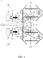
- Fig. 1 shows an optical device 1 of a first embodiment of the disclosure, including a fluorescent wheel 10, a first light source engine 100 and a second light source engine 200.
- Fig. 2 shows a fluorescent wheel 10 of an embodiment of the disclosure.
- the fluorescent wheel 10 includes a fluorescent powder area 15 coated with fluorescent powder.
- the first light source engine 100 provides a first light beam 110.
- the first light beam 110 forms a first light spot 11 on the fluorescent powder area 15 of the fluorescent wheel 10.
- the second light source engine 200 provides a second light beam 210.
- the second light beam 210 forms a second light spot 12 on the fluorescent powder area 15 of the fluorescent wheel 10, and the first light spot 11 is separated from the second light spot 12.
- a first straight line S 1 connects the center C of the fluorescent wheel 10 and the first light spot 11.
- a second straight line S2 connects the center C of the fluorescent wheel 10 and the second light spot 12.
- An included angle ⁇ between the first straight line S1 and the second straight line S2 is between 45 and 180 degrees. In this embodiment, the included angle ⁇ between the first straight line S1 and the second straight line S2 is 180 degrees. In another embodiment, the included angle ⁇ between the first straight line S1 and the second straight line S2 can be 45 degrees.
- the first light spot is separated from the second light spot to decrease the power of single one light spot, and the heat accumulation is therefore decreased.
- the heat accumulation cannot be decreased even if the first light spot is separated from the second light spot.
- the applicant found that the heat accumulation can be markedly decreased by separating the first light spot from the second light spot.
- the phase angle between the first light spot and the second light spot is between 45 and 180 degrees (180 degrees being preferred)
- the heat accumulation is decreased, thermal decay is prevented, and the inducing efficiency of the fluorescent element is maintained.
- the power of the first light spot 11 is 95W
- the power of the second light spot 12 is 95W.
- the temperature of the fluorescent wheel of the embodiment of the disclosure is only 160°C the conventional design is 190°C, and the illumination of the embodiment of the disclosure can be increased 4% to 5%.
- the distance between the first light spot and the center of the fluorescent wheel equals the distance between the second light spot and the center of the fluorescent wheel.
- a first distance d1 is formed between the first light spot 11 and the center C of the fluorescent wheel 10.
- a second distance d2 is formed between the second light spot 12 and the center C of the fluorescent wheel 10.
- the first distance d1 differs from the second distance d2.
- the heat accumulation is further decreased by the difference between the first distance d1 and the second distance d2.
- the power of the first light source engine can be different from the power of the second light source engine to make the temperature of the fluorescent wheel 10 uniform.
- the fluorescent wheel 10 comprises a first transparent portion 13 and a second transparent portion 14.
- the first transparent portion 13 corresponds to the first light source engine 100
- the second transparent portion 14 corresponds to the second light source engine 200.
- the first light beam 110 passes through the first transparent portion 13, and the second light beam 210 passes through the second transparent portion 14.
- the fluorescent wheel 10 rotates continuously. Therefore, when the second transparent portion 14 corresponds to the first light source engine 100, the first transparent portion 13 corresponds to the second light source engine 200.
- the first light beam 110 passes through the second transparent portion 14, and the second light beam 210 passes through the first transparent portion 13.
- the transparent portions can be empty notches or made of transparent material, such as transparent glass.
- the first light source engine is independent from the second light source engine.
- Fig. 1 shows an embodiment of single-chip digital light processing optical device.
- the first light source engine comprises a first light source 120, a first lens unit (L1 ⁇ L10) and a first dichroic mirror 130.
- the first light beam 110 travels from the first light source 120, and passes through a first lens group (L1, L2) of the first lens unit, the first dichroic mirror 130, a second lens group (L3, L4) of the first lens unit, the fluorescent wheel 10, a third lens group (L5, L6, L7, L8, L9) of the first lens unit, and a fourth lens group (L10) of the first lens unit to be output (in one embodiment, a blue light is output, wherein the first light beam 110 passes through the first transparent portion 13 and the second transparent portion 14 of the rotating fluorescent wheel 10).
- the first light beam 110 travels from the first light source 120, passing through the first lens group (L1, L2) of the first lens unit, the first dichroic mirror 130, the second lens group (L3, L4) of the first lens unit to the fluorescent wheel 10, then the light spot 11 is located in the fluorescent powder area 15.
- the fluorescent powder in the fluorescent powder area 15 of the fluorescent wheel 10 is induced by the first light beam 110 and generates a first induced light 111 (in one embodiment, the first induced light is red light and green light).
- the first induced light 111 travels from the fluorescent wheel 10, passing through the second lens group (L4, L3) of the first lens unit, reflected by the first dichroic mirror 130 and passing through the fourth lens group (L10) of the first lens unit to be output.
- the second light source engine comprises a second light source 220, a second lens unit (L21 ⁇ L30) and a second dichroic mirror 230.
- the second light beam 210 travels from the second light source 220, passing through a fifth lens group (L21, L22) of the second lens unit, the second dichroic mirror 230, a sixth lens group (L23, L24) of the second lens unit, the fluorescent wheel 10, a seventh lens group (L25, L26, L27, L28, L29) of the second lens unit, and an eighth lens group (L30) of the second lens unit to be output (in one embodiment, a blue light is output, wherein the first light beam 110 passes through the first transparent portion 13 and the second transparent portion 14 of the rotating fluorescent wheel 10).
- the second light beam 210 travels from the second light source 220, passing through the fifth lens group (L21, L22) of the second lens unit, the second dichroic mirror 230, the sixth lens group (L23, L24) of the second lens unit to the fluorescent wheel 10, then the light spot 12 is located in the fluorescent powder area 15.
- the fluorescent powder in the fluorescent powder area 15 of the fluorescent wheel 10 is induced by the second light beam 210 and generates a second induced light 211 (in one embodiment, the second induced light is red light and green light).
- the second induced light 211 travels from the fluorescent wheel 10, passing through sixth lens group (L24, L23) of the second lens unit, reflected by the second dichroic mirror 230 and passing through the eighth lens group (L30) of the second lens unit to be output.
- the embodiment above shows a single-chip digital light processing optical device. However, the embodiment is not meant to restrict the disclosure.
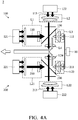
- Fig. 4A shows a three-chip digital light processing optical device 2. In the embodiment of Fig. 4A , the elements with similar functions follow the labels of the embodiment of Fig. 1 .
- the first light source engine 100 comprises a first sub light source 121, a second sub light source 122, a first lens unit (L1 ⁇ L4) and a first dichroic mirror 130.
- the first light beam 110 (in one embodiment, the first light beam is blue light) travels from the first sub light source 121, passing the first lens group (L1) of the first lens unit, the first dichroic mirror 130, and the third lens group (L3) of the first lens unit to the fluorescent wheel 10, the fluorescent powder in the fluorescent powder area 15 of the fluorescent wheel 10 is induced by the first light beam 110 to generate a first induced light 111 (in one embodiment, the first induced light is red light and green light).
- the first induced light 111 travels from the fluorescent wheel 10, passing through the third lens group (L3) of the first lens unit, and reflected by the first dichroic mirror 130 to be output through the fourth lens group (L4) of the first lens unit.
- a third light beam 113 travels from the second light source 122, passing the second lens group (L2) of the first lens unit and the first dichroic mirror 130 to be output through the fourth lens group (L4) of the first lens unit (in one embodiment, the third light beam is blue light).
- the second light source engine 200 comprises a third sub light source 221, a fourth sub light source 222, a second lens unit (L21 ⁇ L24) and a second dichroic mirror 230.
- the second light beam 210 (in one embodiment, the second light beam is blue light) travels from the third sub light source 221, passing the fifth lens group (L21) of the second lens unit, the second dichroic mirror 230 and the seventh lens group (L23) to the fluorescent wheel 10.
- the fluorescent powder in the fluorescent powder area 15 of the fluorescent wheel 10 is induced by the second light beam 210 to generate a second induced light 211 (in one embodiment, the second induced light is red light and blue light), and the second induced light 211 travels from the fluorescent wheel 10, passing through the seventh lens group (L23) of the second lens unit, and reflected by the second dichroic mirror 230 to be output through the eighth lens group (L24) of the second lens unit.
- a fourth light beam 213 travels from the fourth light source 222, passing the sixth lens group (L22) of the second lens unit and the second dichroic mirror 230 to be output through the eighth lens group (L24) of the second lens unit (in one embodiment, the fourth light beam is blue light).
- the fluorescent wheel 10 has no transparent portion.
- a transmissive fluorescent wheel is utilizes.
- the first light source engine 100 of the optical device 3 comprises a first light source 120, a first lens unit (L1 ⁇ L3) and a first reflector 140.
- the first light beam 110 (in this embodiment, the first light beam is blue light) travels from the first light source 120, passing through the first lens group (L1) of the first lens unit and the fluorescent wheel 10, the second lens group (L2) of the first lens unit, the first reflector 140 and the third lens group (L3) of the first lens unit to be output.
- a plurality of gaps are formed within the fluorescent powder in the fluorescent powder area 15 of the fluorescent wheel 10.
- the second light source engine 200 comprises a second light source 220, a second lens unit (L21 ⁇ L23) and a second reflector 240.
- the second light beam 210 (in this embodiment, the second light beam is blue light) travels from the second light source 220, passing through the fourth lens group (L21) of the second lens unit, the fluorescent wheel, the fifth lens group (L22) of the second lens unit, the second reflector 240 and the six lens group (L23) of the second lens unit to be output.
- a plurality of gaps are formed within the fluorescent powder in the fluorescent powder area 15 of the fluorescent wheel 10. Therefore, a portion of the second light beam 210 directly passing through the fluorescent wheel 10 via the gaps, and the fluorescent powder in the fluorescent powder area 15 of the fluorescent wheel is induced by the other portion of the second light beam 210 to generate a second induced light (in this embodiment, the second induced light is red light and green light).
- the second induced light passes through the fluorescent wheel 10 (the second induced light and the portion of the second light beam directly passing through the fluorescent wheel are presented by a second combination light 214).
- the second combination light 214 is reflected by the second reflector 240 to be output.
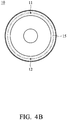
- Figs. 5B and 5C show the fluorescent wheel 10 of the embodiment of Fig. 5A , wherein the fluorescent wheel 10 has no transparent portion.
- the fluorescent wheel 10 comprises a transmissive substrate 17, a spectral coating layer 16 and a fluorescent agents coating layer 18.
- the transmissive substrate 17 is made of glass.
- the spectral coating layer 16 allows a blue light to pass through and reflects a yellow light.
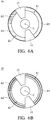
- Figs. 6A and 6B show another embodiment of the disclosure, wherein the fluorescent wheel 10 has a first transparent portion 13 and a second transparent portion 14.
- the fluorescent powder area of the fluorescent wheel 10 comprises a first section (green fluorescent powder) A1, a second section (yellow fluorescent powder) A2 and a third section (yellow fluorescent powder) A3.
- the color of the first section A1 differs from the color of the second section A2.
- the color of the third section A3 differs from the color of the first section A1.
- the first section A1, the second section A2 and the third section A3 are arranged along the circumference of the fluorescent wheel.
- the color of the second section A2 is the same as the color of the third section A3, however, the disclosure is not meant to restrict the disclosure.
- a first distance is formed between the first light spot 11 and the center C of the fluorescent wheel 10.
- a second distance is formed between the second light spot 12 and the center C of the fluorescent wheel 10.
- the first distance can be the same as the second distance ( Fig. 6A ). In another embodiment, the first distance can be different from the second distance ( Fig. 6B ).
- the colors of the first section, the second section and the third section can be modified in other embodiments.
Landscapes
- Physics & Mathematics (AREA)
- Engineering & Computer Science (AREA)
- General Physics & Mathematics (AREA)
- General Engineering & Computer Science (AREA)
- Multimedia (AREA)
- Optics & Photonics (AREA)
- Projection Apparatus (AREA)
- Non-Portable Lighting Devices Or Systems Thereof (AREA)
- Spectroscopy & Molecular Physics (AREA)
Claims (12)
- Optische Vorrichtung (1), umfassend:ein Fluoreszenzrad (10), das einen fluoreszierenden Pulverbereich (15) aufweist;eine erste Lichtquelleneinrichtung (100), die einen ersten Lichtstrahl (110) bereitstellt, wobei der erste Lichtstrahl (110) einen ersten Lichtfleck (11) auf dem fluoreszierenden Pulverbereich (15) des Fluoreszenzrades (10) ausbildet; undeine zweite Lichtquelleneinrichtung (200), die einen zweiten Lichtstrahl (210) bereitstellt, wobei der zweite Lichtstrahl (210) einen zweiten Lichtfleck (12) auf dem fluoreszierenden Pulverbereich (15) des Fluoreszenzrades (10) ausbildet und der erste Lichtfleck (11) von dem zweiten Lichtfleck (12) getrennt ist;dadurch gekennzeichnet, dassdas Fluoreszenzrad (10) ferner einen ersten Spalt (13) und einen zweiten Spalt (14) umfasst, wobei der erste Spalt (13) und der zweite Spalt (14) so ausgelegt sind, dass der erste Lichtstrahl (110) oder der zweite Lichtstrahl (210) jeweils einen der Spalte (13, 14) durchlaufen kann, anstatt den ersten Lichtfleck (11) und den zweiten Lichtfleck (12) auf dem Fluoreszenzrad (10) auszubilden.
- Optische Vorrichtung (1) nach Anspruch 1, wobei ein Winkel (θ), der zwischen einer ersten geraden Linie (S1), die einen Mittelpunkt (C) des Fluoreszenzrades (10) und den ersten Lichtfleck (11) miteinander verbindet, und einer zweiten geraden Linie (S2), die den Mittelpunkt (C) des Fluoreszenzrades (10) und den zweiten Lichtfleck (12) miteinander verbindet, liegt, im Bereich zwischen 45° und 180° liegt.
- Optische Vorrichtung (1) nach Anspruch 1 oder 2, wobei zwischen dem ersten Lichtfleck (11) und einem Mittelpunkt (C) des Fluoreszenzrades (10) ein erster Abstand (d1) ausgebildet ist, zwischen dem zweiten Lichtfleck (12) und dem Mittelpunkt (C) des Fluoreszenzrades (10) ein zweiter Abstand (D2) ausgebildet ist und der erste Abstand (d1) von dem zweiten Abstand (d2) abweicht.
- Optische Vorrichtung (1) nach einem der vorangehenden Ansprüche, wobei wenn der erste Spalt (13) der ersten Lichtquelleneinrichtung (100) zugeordnet ist, der zweite Spalt (14) der zweiten Lichtquelleneinrichtung (200) zugeordnet ist, und wobei der erste Lichtstrahl (110) den ersten Spalt (13) durchläuft und der zweite Lichtstrahl (210) den zweiten Spalt (14) durchläuft.
- Optische Vorrichtung (1) nach einem der vorhergehenden Ansprüche, wobei die erste Lichtquelleneinrichtung (100) unabhängig von der zweiten Lichtquelleneinrichtung (200) ist.
- Optische Vorrichtung (1) nach Anspruch 4, wobei
die erste Lichtquelleneinrichtung (100) eine erste Lichtquelle (120), eine erste Linseneinheit und einen ersten dichroitischen Spiegel (130) umfasst, wobei
in einem ersten Betriebszustand der erste Lichtstrahl (110) von der ersten Lichtquelle (120) abgestrahlt wird und eine erste Linsengruppe (L1, L2) der ersten Linseneinheit (120), den ersten dichroitischen Spiegel (130), eine zweite Linsengruppe (L3, L4) der ersten Linseneinheit, den ersten Spalt (13) oder den zweiten Spalt (14) des Fluoreszenzrades (10), eine dritte Linsengruppe (L5, L6, L7, L8, L9) der ersten Linseneinheit und eine vierte Linsengruppe (L10) der ersten Linseneinheit passiert, um ausgegeben zu werden, wobei
in einem zweiten Betriebszustand der erste Lichtstrahl (110) von der ersten Lichtquelle (120) abgestrahlt wird, die erste Linsengruppe (L1, L2) der ersten Linseneinheit, den ersten dichroitischen Spiegel (130) und die zweite Linsengruppe (L3, L4) der ersten Linseneinheit bis zum Fluoreszenzrad (10) passiert und
das fluoreszierende Pulver (10) in dem ersten fluoreszierenden Pulverbereich (15) des Fluoreszenzrades (10) durch den ersten Lichtstrahl (110) angeregt wird und ein erstes induziertes Licht (111) erzeugt und das erste induzierte Licht (111) sich ausgehend von dem Fluoreszenzrad (10) durch die zweite Linsengruppe (L3, L4) der ersten Linseneinheit ausbreitet, von dem ersten dichroitischen Spiegel (130) reflektiert wird und sich durch die vierte Linsengruppe (L10) der ersten Linseneinheit ausbreitet, um ausgegeben zu werden. - Optische Vorrichtung (1) nach Anspruch 6, wobei
die zweite Lichtquelleneinrichtung (200) eine zweite Lichtquelle (220), eine zweite Linseneinheit und einen zweiten dichroitischen Spiegel (230) aufweist, wobei
in dem ersten Betriebszustand der zweite Lichtstrahl (210) von der zweiten Lichtquelle (220) abgestrahlt wird und sich entlang einer fünften Linsengruppe (L21, L22) der zweiten Linseneinheit, dem zweiten dichroitischen Spiegel (230), einer sechsten Linse (L23, L24) der zweiten Linseneinheit, dem ersten Spalt (13) oder dem zweiten Spalt (14) des Fluoreszenzrades (10), einer siebten Linsengruppe (L25, L26, L27, L28, L29) der zweiten Linseneinheit und einer achten Linsengruppe (L30) der zweiten Linseneinheit ausbreitet, um ausgegeben zu werden, wobei
in dem zweiten Betriebszustand der zweite Lichtstrahl (210) von der zweiten Lichtquelle abgestrahlt wird und sich durch die fünfte Linsengruppe (L21, L22) der zweiten Linseneinheit, entlang dem zweiten dichroitischen Spiegel (230) und durch die sechste Linsengruppe (L23, L24) der zweiten Linseneinheit hin zum Fluoreszenzrad (10) ausbreitet und
das fluoreszierende Pulver in der fluoreszierenden Pulverbereich (15) des Fluoreszenzrades (10) durch den zweiten Lichtstrahl (210) angeregt wird und ein zweites induziertes Licht (211) erzeugt und das zweite induzierte Licht (211) von dem Fluoreszenzrad (10) abgestrahlt wird und die sechste Linsengruppe (L23, L24) der zweiten Linseneinheit durchläuft, von dem zweiten dichroitischen Spiegel (230) reflektiert wird und die achte Linsengruppe (L30) der zweiten Linseneinheit durchläuft, um ausgegeben zu werden. - Optische Vorrichtung (1) nach einem der vorhergehenden Ansprüche, wobei
die erste Lichtquelleneinrichtung (100) eine erste Teillichtquelle (121), eine zweite Teillichtquelle (122), eine erste Linseneinheit (L1 ∼ L4) und einen ersten dichroitischen Spiegel (130) aufweist, wobei der erste Lichtstrahl (110) von der ersten Teillichtquelle (121) abgestrahlt wird und einen Abschnitt der ersten Linseneinheit (L1 ∼ L4) und den ersten dichroitischen Spiegel (10) bis zum Fluoreszenzrad (10) passiert, fluoreszierende Pulver in dem fluoreszierenden Pulverbereich (15) des Fluoreszenzrades (10) durch den ersten Lichtstrahl (110) angeregt wird, um ein erstes induziertes Licht (111) zu erzeugen, und das erste induzierte Licht (111) sich ausgehend von dem Fluoreszenzrad (10) ausbreitet, einen Abschnitt der ersten Linseneinheit (L1 ∼ L4) durchläuft und von dem ersten dichroitischen Spiegel (130) reflektiert wird um ausgegeben zu werden, und wobei sich ein dritter Lichtstrahl (113) ausgehend von der zweiten Lichtquelle (122) ausbreitet und einen Abschnitt der ersten Linseneinheit (L1 ∼ L4) und den ersten dichroitischen Spiegel (130) passiert, um ausgegeben zu werden. - Optische Vorrichtung (1) nach Anspruch 8, wobei die zweite Lichtquelleneinrichtung (200) eine dritte Teillichtquelle (221), eine vierte Teillichtquelle (222), eine zweite Linseneinheit (L21 ∼ L24)) und einen zweiten dichroitischen Spiegel aufweist, wobei sich der zweite Lichtstrahl (210) ausgehend von der dritten Teillichtquelle (221) ausbreitet und einen Abschnitt der zweiten Linseneinheit (L21 ∼ L24) und den zweiten dichroitischen Spiegel (230) bis zum Fluoreszenzrad (10) passiert, das fluoreszierende Pulver in dem fluoreszierenden Pulverbereich (15) des Fluoreszenzrads (10) durch den zweiten Lichtstrahl (210) angeregt wird, um ein zweites induziertes Licht (211) zu erzeugen, und das zweite induzierte Licht (211) sich ausgehend von dem Fluoreszenzrad (10) ausbreitet, einen Abschnitt der zweiten Linseneinheit (L21 ∼ L24) durchläuft und von dem zweiten dichroitischen Spiegel (230) reflektiert wird um ausgegeben zu werden, und wobei sich ein vierter Lichtstrahl (213) ausgehend von der vierten Teillichtquelle (222) ausbreitet, einen Abschnitt der zweiten Linseneinheit (L21 ∼ L24) und den zweiten dichroitischen Spiegel (230) passiert, um ausgegeben zu werden.
- Optische Vorrichtung (1) nach Anspruch 4, wobei die erste Lichtquelleneinrichtung (100) eine erste Lichtquelle (120), eine erste Linseneinheit (L1 ∼ L3) und einen ersten Reflektor (140) umfasst, wobei sich der erste Lichtstrahl (110) ausgehend von der ersten Lichtquelle (120) ausbreitet, einen Abschnitt der ersten Linseneinheit (L1 ∼ L3) und das Fluoreszenzrad (10) passiert, ein Teil des ersten Lichtstrahls (110) direkt das Fluoreszenzrad (10) durchläuft, ein fluoreszierendes Pulver in dem fluoreszierenden Pulverbereich (15) des Fluoreszenzrades (10) durch den anderen Teil des ersten Lichtstrahls (110) angeregt wird, um ein erstes induziertes Licht zu erzeugen, und wobei das erste induzierte Licht durch das Fluoreszenzrad (10) hindurchtritt und wobei sowohl das erste induzierte Licht als auch der Teil des ersten Lichtstrahls (110), der direkt das Fluoreszenzrad (10) durchläuft, von dem ersten Reflektor (140) reflektiert wird, um ausgegeben zu werden.
- Optische Vorrichtung (1) nach Anspruch 10, wobei die zweite Lichtquelleneinrichtung (200) eine zweite Lichtquelle (220), eine zweite Linseneinheit (L21 ∼ L23) und einen zweiten Reflektor (240) umfasst, wobei der zweite Lichtstrahl (210) sich ausgehend von der zweiten Lichtquelle (220) ausbreitet und einen Abschnitt der zweiten Linseneinheit (L21 ∼ L23) und das Fluoreszenzrad (10) passiert, wobei ein Teil des zweiten Lichtstrahls (210) das Fluoreszenzrad (10) direkt durchläuft, das fluoreszierende Pulver in dem fluoreszierenden Pulverbereich (15) des Fluoreszenzrades (10) durch den anderen Teil des zweiten Lichtstrahls (210) angeregt wird, um ein zweites induziertes Licht zu erzeugen, und wobei das zweite induzierte Licht durch das Fluoreszenzrad (10) hindurchtritt und wobei sowohl das zweite induzierte Licht als auch der Teil des zweiten Lichtstrahls (210), der direkt durch das Fluoreszenzrad (10) hindurchtritt, von dem zweiten Reflektor (240) reflektiert werden, um ausgegeben zu werden.
- Optische Vorrichtung (1) nach einem der Ansprüche 1 bis 11, wobei der fluoreszierende Pulverbereich (15) des Fluoreszenzrades (10) einen ersten Abschnitt (A1), einen zweiten Abschnitt (A2) und einen dritten Abschnitt (A3) aufweist, wobei sich die Farbe des ersten Abschnitts (A1) von der Farbe des zweiten Abschnitts (A2) unterscheidet, die Farbe des dritten Abschnitts (A3) sich von der Farbe des ersten Abschnitts (A1) unterscheidet und der zweite Abschnitt (A2) und der dritte Abschnitt (A3) entlang eines Umfangs des Fluoreszenzrades (10) angeordnet sind.
Applications Claiming Priority (1)
| Application Number | Priority Date | Filing Date | Title |
|---|---|---|---|
| US201562136126P | 2015-03-20 | 2015-03-20 |
Publications (2)
| Publication Number | Publication Date |
|---|---|
| EP3070525A1 EP3070525A1 (de) | 2016-09-21 |
| EP3070525B1 true EP3070525B1 (de) | 2017-11-01 |
Family
ID=54834658
Family Applications (1)
| Application Number | Title | Priority Date | Filing Date |
|---|---|---|---|
| EP15197987.9A Active EP3070525B1 (de) | 2015-03-20 | 2015-12-04 | Optische vorrichtung |
Country Status (5)
| Country | Link |
|---|---|
| US (1) | US10088130B2 (de) |
| EP (1) | EP3070525B1 (de) |
| JP (1) | JP6207649B2 (de) |
| CN (1) | CN105988274A (de) |
| TW (1) | TWI585505B (de) |
Families Citing this family (3)
| Publication number | Priority date | Publication date | Assignee | Title |
|---|---|---|---|---|
| CN106527026A (zh) * | 2016-12-09 | 2017-03-22 | 上海晟智电子科技有限公司 | 一种激光投影光源实现装置及方法 |
| CN108267913B (zh) * | 2016-12-30 | 2021-06-08 | 中强光电股份有限公司 | 光源模块以及投影装置 |
| CN113138525B (zh) * | 2020-01-20 | 2024-03-22 | 苏州佳世达光电有限公司 | 投影装置 |
Family Cites Families (14)
| Publication number | Priority date | Publication date | Assignee | Title |
|---|---|---|---|---|
| TW200700883A (en) * | 2005-06-20 | 2007-01-01 | Benq Corp | Light source module of a projector and color wheel thereof |
| JP5617288B2 (ja) * | 2010-03-18 | 2014-11-05 | セイコーエプソン株式会社 | 照明装置及びプロジェクター |
| JP5767444B2 (ja) * | 2010-06-16 | 2015-08-19 | ソニー株式会社 | 光源装置及び画像投影装置 |
| JP5914878B2 (ja) * | 2011-04-20 | 2016-05-11 | パナソニックIpマネジメント株式会社 | 光源装置及び投写型表示装置 |
| JP5870259B2 (ja) * | 2011-05-25 | 2016-02-24 | パナソニックIpマネジメント株式会社 | 照明装置および該照明装置を備える投射型表示装置 |
| JP5987382B2 (ja) * | 2011-07-22 | 2016-09-07 | 株式会社リコー | 照明装置、ならびに、投射装置および投射装置の制御方法 |
| TWI439793B (zh) * | 2011-08-03 | 2014-06-01 | Hon Hai Prec Ind Co Ltd | 投影機光源裝置 |
| CN103246145B (zh) * | 2012-02-09 | 2015-02-18 | 台达电子工业股份有限公司 | 光源系统 |
| TWI467242B (zh) * | 2012-05-29 | 2015-01-01 | Delta Electronics Inc | 提供複數視角影像之投影裝置 |
| CN202771146U (zh) | 2012-07-12 | 2013-03-06 | 芜湖雅图数字视频技术有限公司 | 一种双灯照明装置及投影仪 |
| WO2014174559A1 (ja) * | 2013-04-22 | 2014-10-30 | 日立マクセル株式会社 | 光源装置及び映像表示装置 |
| TWI468842B (zh) * | 2013-05-07 | 2015-01-11 | 台達電子工業股份有限公司 | 用於調控投影裝置的出光波長之方法 |
| US9664989B2 (en) | 2013-05-23 | 2017-05-30 | Texas Instruments Incorporated | Multi-spatial light modulator image display projector architectures using solid state light sources |
| TW201503515A (zh) * | 2013-07-12 | 2015-01-16 | Delta Electronics Inc | 適用於投影系統之雷射光源模組 |
-
2015
- 2015-07-03 CN CN201510385594.7A patent/CN105988274A/zh active Pending
- 2015-07-03 TW TW104121612A patent/TWI585505B/zh active
- 2015-11-24 US US14/950,920 patent/US10088130B2/en active Active
- 2015-12-04 EP EP15197987.9A patent/EP3070525B1/de active Active
-
2016
- 2016-03-18 JP JP2016054705A patent/JP6207649B2/ja active Active
Non-Patent Citations (1)
| Title |
|---|
| None * |
Also Published As
| Publication number | Publication date |
|---|---|
| TW201635003A (zh) | 2016-10-01 |
| US10088130B2 (en) | 2018-10-02 |
| EP3070525A1 (de) | 2016-09-21 |
| US20160273737A1 (en) | 2016-09-22 |
| JP2016177286A (ja) | 2016-10-06 |
| CN105988274A (zh) | 2016-10-05 |
| TWI585505B (zh) | 2017-06-01 |
| JP6207649B2 (ja) | 2017-10-04 |
Similar Documents
| Publication | Publication Date | Title |
|---|---|---|
| US9175829B2 (en) | Illumination apparatus with phosphor wheel | |
| TWI486699B (zh) | 光源系統 | |
| US9798134B2 (en) | Side-illuminated excitation optics apparatus and systems | |
| JP6419729B2 (ja) | 車両用灯具 | |
| CN104870887B (zh) | 光源装置 | |
| US7506985B2 (en) | Projection light source having multiple light emitting diodes | |
| KR20080085732A (ko) | 백색 광원 장치 | |
| CN102971672A (zh) | 包括固态光源和发光材料的投影系统 | |
| CN205450551U (zh) | 色轮模组、光源模组和投影系统 | |
| EP3070525B1 (de) | Optische vorrichtung | |
| CN103946629A (zh) | 在能运动的载体上具有荧光材料的照明装置 | |
| JP2015146396A (ja) | 発光装置、車両用灯具、及び、車両用照明装置 | |
| US11493838B2 (en) | Optical device | |
| CN105223760A (zh) | 波长转换装置及投影机 | |
| TWM337676U (en) | LED projection lamp | |
| JP2015184407A (ja) | 照明装置および映像表示装置 | |
| CN210573158U (zh) | 激光光源系统、投影机及照明设备 | |
| JP2016177272A (ja) | 光源装置および投写型表示装置 | |
| WO2012172672A1 (ja) | 蛍光体カラーホイルおよびそれを内蔵する投写型表示装置 | |
| TWM536329U (zh) | 照明裝置 | |
| CN108292085A (zh) | 投影仪装置 | |
| JP5623937B2 (ja) | 照明装置用レンズおよび照明装置 | |
| RU2543402C2 (ru) | Световой сигнал | |
| CN210038428U (zh) | 光源装置、激光投影装置以及车辆照明灯 | |
| TWI587066B (zh) | 光學裝置 |
Legal Events
| Date | Code | Title | Description |
|---|---|---|---|
| PUAI | Public reference made under article 153(3) epc to a published international application that has entered the european phase |
Free format text: ORIGINAL CODE: 0009012 |
|
| AK | Designated contracting states |
Kind code of ref document: A1 Designated state(s): AL AT BE BG CH CY CZ DE DK EE ES FI FR GB GR HR HU IE IS IT LI LT LU LV MC MK MT NL NO PL PT RO RS SE SI SK SM TR |
|
| AX | Request for extension of the european patent |
Extension state: BA ME |
|
| 17P | Request for examination filed |
Effective date: 20170209 |
|
| RBV | Designated contracting states (corrected) |
Designated state(s): AL AT BE BG CH CY CZ DE DK EE ES FI FR GB GR HR HU IE IS IT LI LT LU LV MC MK MT NL NO PL PT RO RS SE SI SK SM TR |
|
| GRAP | Despatch of communication of intention to grant a patent |
Free format text: ORIGINAL CODE: EPIDOSNIGR1 |
|
| RAP1 | Party data changed (applicant data changed or rights of an application transferred) |
Owner name: DELTA ELECTRONICS, INC. |
|
| INTG | Intention to grant announced |
Effective date: 20170530 |
|
| GRAS | Grant fee paid |
Free format text: ORIGINAL CODE: EPIDOSNIGR3 |
|
| GRAA | (expected) grant |
Free format text: ORIGINAL CODE: 0009210 |
|
| AK | Designated contracting states |
Kind code of ref document: B1 Designated state(s): AL AT BE BG CH CY CZ DE DK EE ES FI FR GB GR HR HU IE IS IT LI LT LU LV MC MK MT NL NO PL PT RO RS SE SI SK SM TR |
|
| REG | Reference to a national code |
Ref country code: GB Ref legal event code: FG4D |
|
| REG | Reference to a national code |
Ref country code: CH Ref legal event code: EP Ref country code: AT Ref legal event code: REF Ref document number: 942618 Country of ref document: AT Kind code of ref document: T Effective date: 20171115 |
|
| REG | Reference to a national code |
Ref country code: FR Ref legal event code: PLFP Year of fee payment: 3 |
|
| REG | Reference to a national code |
Ref country code: IE Ref legal event code: FG4D |
|
| REG | Reference to a national code |
Ref country code: DE Ref legal event code: R096 Ref document number: 602015005716 Country of ref document: DE |
|
| REG | Reference to a national code |
Ref country code: NL Ref legal event code: MP Effective date: 20171101 |
|
| REG | Reference to a national code |
Ref country code: LT Ref legal event code: MG4D |
|
| REG | Reference to a national code |
Ref country code: AT Ref legal event code: MK05 Ref document number: 942618 Country of ref document: AT Kind code of ref document: T Effective date: 20171101 |
|
| PG25 | Lapsed in a contracting state [announced via postgrant information from national office to epo] |
Ref country code: FI Free format text: LAPSE BECAUSE OF FAILURE TO SUBMIT A TRANSLATION OF THE DESCRIPTION OR TO PAY THE FEE WITHIN THE PRESCRIBED TIME-LIMIT Effective date: 20171101 Ref country code: SE Free format text: LAPSE BECAUSE OF FAILURE TO SUBMIT A TRANSLATION OF THE DESCRIPTION OR TO PAY THE FEE WITHIN THE PRESCRIBED TIME-LIMIT Effective date: 20171101 Ref country code: NL Free format text: LAPSE BECAUSE OF FAILURE TO SUBMIT A TRANSLATION OF THE DESCRIPTION OR TO PAY THE FEE WITHIN THE PRESCRIBED TIME-LIMIT Effective date: 20171101 Ref country code: ES Free format text: LAPSE BECAUSE OF FAILURE TO SUBMIT A TRANSLATION OF THE DESCRIPTION OR TO PAY THE FEE WITHIN THE PRESCRIBED TIME-LIMIT Effective date: 20171101 Ref country code: LT Free format text: LAPSE BECAUSE OF FAILURE TO SUBMIT A TRANSLATION OF THE DESCRIPTION OR TO PAY THE FEE WITHIN THE PRESCRIBED TIME-LIMIT Effective date: 20171101 Ref country code: NO Free format text: LAPSE BECAUSE OF FAILURE TO SUBMIT A TRANSLATION OF THE DESCRIPTION OR TO PAY THE FEE WITHIN THE PRESCRIBED TIME-LIMIT Effective date: 20180201 |
|
| PG25 | Lapsed in a contracting state [announced via postgrant information from national office to epo] |
Ref country code: LV Free format text: LAPSE BECAUSE OF FAILURE TO SUBMIT A TRANSLATION OF THE DESCRIPTION OR TO PAY THE FEE WITHIN THE PRESCRIBED TIME-LIMIT Effective date: 20171101 Ref country code: BG Free format text: LAPSE BECAUSE OF FAILURE TO SUBMIT A TRANSLATION OF THE DESCRIPTION OR TO PAY THE FEE WITHIN THE PRESCRIBED TIME-LIMIT Effective date: 20180201 Ref country code: HR Free format text: LAPSE BECAUSE OF FAILURE TO SUBMIT A TRANSLATION OF THE DESCRIPTION OR TO PAY THE FEE WITHIN THE PRESCRIBED TIME-LIMIT Effective date: 20171101 Ref country code: RS Free format text: LAPSE BECAUSE OF FAILURE TO SUBMIT A TRANSLATION OF THE DESCRIPTION OR TO PAY THE FEE WITHIN THE PRESCRIBED TIME-LIMIT Effective date: 20171101 Ref country code: AT Free format text: LAPSE BECAUSE OF FAILURE TO SUBMIT A TRANSLATION OF THE DESCRIPTION OR TO PAY THE FEE WITHIN THE PRESCRIBED TIME-LIMIT Effective date: 20171101 Ref country code: GR Free format text: LAPSE BECAUSE OF FAILURE TO SUBMIT A TRANSLATION OF THE DESCRIPTION OR TO PAY THE FEE WITHIN THE PRESCRIBED TIME-LIMIT Effective date: 20180202 Ref country code: IS Free format text: LAPSE BECAUSE OF FAILURE TO SUBMIT A TRANSLATION OF THE DESCRIPTION OR TO PAY THE FEE WITHIN THE PRESCRIBED TIME-LIMIT Effective date: 20180301 |
|
| PG25 | Lapsed in a contracting state [announced via postgrant information from national office to epo] |
Ref country code: CZ Free format text: LAPSE BECAUSE OF FAILURE TO SUBMIT A TRANSLATION OF THE DESCRIPTION OR TO PAY THE FEE WITHIN THE PRESCRIBED TIME-LIMIT Effective date: 20171101 Ref country code: DK Free format text: LAPSE BECAUSE OF FAILURE TO SUBMIT A TRANSLATION OF THE DESCRIPTION OR TO PAY THE FEE WITHIN THE PRESCRIBED TIME-LIMIT Effective date: 20171101 Ref country code: EE Free format text: LAPSE BECAUSE OF FAILURE TO SUBMIT A TRANSLATION OF THE DESCRIPTION OR TO PAY THE FEE WITHIN THE PRESCRIBED TIME-LIMIT Effective date: 20171101 Ref country code: CY Free format text: LAPSE BECAUSE OF FAILURE TO SUBMIT A TRANSLATION OF THE DESCRIPTION OR TO PAY THE FEE WITHIN THE PRESCRIBED TIME-LIMIT Effective date: 20171101 Ref country code: SK Free format text: LAPSE BECAUSE OF FAILURE TO SUBMIT A TRANSLATION OF THE DESCRIPTION OR TO PAY THE FEE WITHIN THE PRESCRIBED TIME-LIMIT Effective date: 20171101 |
|
| REG | Reference to a national code |
Ref country code: DE Ref legal event code: R097 Ref document number: 602015005716 Country of ref document: DE |
|
| PG25 | Lapsed in a contracting state [announced via postgrant information from national office to epo] |
Ref country code: RO Free format text: LAPSE BECAUSE OF FAILURE TO SUBMIT A TRANSLATION OF THE DESCRIPTION OR TO PAY THE FEE WITHIN THE PRESCRIBED TIME-LIMIT Effective date: 20171101 Ref country code: SM Free format text: LAPSE BECAUSE OF FAILURE TO SUBMIT A TRANSLATION OF THE DESCRIPTION OR TO PAY THE FEE WITHIN THE PRESCRIBED TIME-LIMIT Effective date: 20171101 Ref country code: IT Free format text: LAPSE BECAUSE OF FAILURE TO SUBMIT A TRANSLATION OF THE DESCRIPTION OR TO PAY THE FEE WITHIN THE PRESCRIBED TIME-LIMIT Effective date: 20171101 Ref country code: PL Free format text: LAPSE BECAUSE OF FAILURE TO SUBMIT A TRANSLATION OF THE DESCRIPTION OR TO PAY THE FEE WITHIN THE PRESCRIBED TIME-LIMIT Effective date: 20171101 |
|
| PLBE | No opposition filed within time limit |
Free format text: ORIGINAL CODE: 0009261 |
|
| STAA | Information on the status of an ep patent application or granted ep patent |
Free format text: STATUS: NO OPPOSITION FILED WITHIN TIME LIMIT |
|
| REG | Reference to a national code |
Ref country code: IE Ref legal event code: MM4A |
|
| PG25 | Lapsed in a contracting state [announced via postgrant information from national office to epo] |
Ref country code: LU Free format text: LAPSE BECAUSE OF NON-PAYMENT OF DUE FEES Effective date: 20171204 Ref country code: MT Free format text: LAPSE BECAUSE OF NON-PAYMENT OF DUE FEES Effective date: 20171204 |
|
| 26N | No opposition filed |
Effective date: 20180802 |
|
| REG | Reference to a national code |
Ref country code: FR Ref legal event code: PLFP Year of fee payment: 4 |
|
| PG25 | Lapsed in a contracting state [announced via postgrant information from national office to epo] |
Ref country code: IE Free format text: LAPSE BECAUSE OF NON-PAYMENT OF DUE FEES Effective date: 20171204 |
|
| PG25 | Lapsed in a contracting state [announced via postgrant information from national office to epo] |
Ref country code: SI Free format text: LAPSE BECAUSE OF FAILURE TO SUBMIT A TRANSLATION OF THE DESCRIPTION OR TO PAY THE FEE WITHIN THE PRESCRIBED TIME-LIMIT Effective date: 20171101 |
|
| PG25 | Lapsed in a contracting state [announced via postgrant information from national office to epo] |
Ref country code: MC Free format text: LAPSE BECAUSE OF FAILURE TO SUBMIT A TRANSLATION OF THE DESCRIPTION OR TO PAY THE FEE WITHIN THE PRESCRIBED TIME-LIMIT Effective date: 20171101 Ref country code: HU Free format text: LAPSE BECAUSE OF FAILURE TO SUBMIT A TRANSLATION OF THE DESCRIPTION OR TO PAY THE FEE WITHIN THE PRESCRIBED TIME-LIMIT; INVALID AB INITIO Effective date: 20151204 |
|
| REG | Reference to a national code |
Ref country code: CH Ref legal event code: PL |
|
| PG25 | Lapsed in a contracting state [announced via postgrant information from national office to epo] |
Ref country code: MK Free format text: LAPSE BECAUSE OF FAILURE TO SUBMIT A TRANSLATION OF THE DESCRIPTION OR TO PAY THE FEE WITHIN THE PRESCRIBED TIME-LIMIT Effective date: 20171101 |
|
| PG25 | Lapsed in a contracting state [announced via postgrant information from national office to epo] |
Ref country code: CH Free format text: LAPSE BECAUSE OF NON-PAYMENT OF DUE FEES Effective date: 20181231 Ref country code: LI Free format text: LAPSE BECAUSE OF NON-PAYMENT OF DUE FEES Effective date: 20181231 |
|
| PG25 | Lapsed in a contracting state [announced via postgrant information from national office to epo] |
Ref country code: TR Free format text: LAPSE BECAUSE OF FAILURE TO SUBMIT A TRANSLATION OF THE DESCRIPTION OR TO PAY THE FEE WITHIN THE PRESCRIBED TIME-LIMIT Effective date: 20171101 |
|
| PG25 | Lapsed in a contracting state [announced via postgrant information from national office to epo] |
Ref country code: PT Free format text: LAPSE BECAUSE OF FAILURE TO SUBMIT A TRANSLATION OF THE DESCRIPTION OR TO PAY THE FEE WITHIN THE PRESCRIBED TIME-LIMIT Effective date: 20171101 |
|
| PG25 | Lapsed in a contracting state [announced via postgrant information from national office to epo] |
Ref country code: AL Free format text: LAPSE BECAUSE OF FAILURE TO SUBMIT A TRANSLATION OF THE DESCRIPTION OR TO PAY THE FEE WITHIN THE PRESCRIBED TIME-LIMIT Effective date: 20171101 |
|
| PGFP | Annual fee paid to national office [announced via postgrant information from national office to epo] |
Ref country code: DE Payment date: 20251022 Year of fee payment: 11 |
|
| PGFP | Annual fee paid to national office [announced via postgrant information from national office to epo] |
Ref country code: GB Payment date: 20251016 Year of fee payment: 11 |
|
| PGFP | Annual fee paid to national office [announced via postgrant information from national office to epo] |
Ref country code: FR Payment date: 20251023 Year of fee payment: 11 |
|
| PGFP | Annual fee paid to national office [announced via postgrant information from national office to epo] |
Ref country code: BE Payment date: 20251117 Year of fee payment: 11 |