EP3070511A2 - Electronic device having heat radiator and method for controlling the electronic device - Google Patents
Electronic device having heat radiator and method for controlling the electronic device Download PDFInfo
- Publication number
- EP3070511A2 EP3070511A2 EP16157122.9A EP16157122A EP3070511A2 EP 3070511 A2 EP3070511 A2 EP 3070511A2 EP 16157122 A EP16157122 A EP 16157122A EP 3070511 A2 EP3070511 A2 EP 3070511A2
- Authority
- EP
- European Patent Office
- Prior art keywords
- electronic device
- fan
- heat
- portable electronic
- frame
- Prior art date
- Legal status (The legal status is an assumption and is not a legal conclusion. Google has not performed a legal analysis and makes no representation as to the accuracy of the status listed.)
- Granted
Links
- 238000000034 method Methods 0.000 title abstract description 21
- 230000003287 optical effect Effects 0.000 claims abstract description 16
- 238000009792 diffusion process Methods 0.000 claims description 29
- 238000012546 transfer Methods 0.000 claims description 29
- 238000001514 detection method Methods 0.000 claims description 20
- 210000003128 head Anatomy 0.000 claims description 15
- 230000004044 response Effects 0.000 claims description 5
- 239000000463 material Substances 0.000 description 16
- 238000004891 communication Methods 0.000 description 13
- 230000006870 function Effects 0.000 description 12
- OKTJSMMVPCPJKN-UHFFFAOYSA-N Carbon Chemical compound [C] OKTJSMMVPCPJKN-UHFFFAOYSA-N 0.000 description 8
- 238000010586 diagram Methods 0.000 description 8
- 230000033001 locomotion Effects 0.000 description 6
- 238000013459 approach Methods 0.000 description 5
- -1 electricity Substances 0.000 description 5
- 239000011521 glass Substances 0.000 description 4
- 229910052751 metal Inorganic materials 0.000 description 4
- 239000002184 metal Substances 0.000 description 4
- 229910052799 carbon Inorganic materials 0.000 description 3
- 238000009833 condensation Methods 0.000 description 3
- 230000005494 condensation Effects 0.000 description 3
- 238000007599 discharging Methods 0.000 description 3
- 239000013013 elastic material Substances 0.000 description 3
- 230000014509 gene expression Effects 0.000 description 3
- 238000012986 modification Methods 0.000 description 3
- 230000004048 modification Effects 0.000 description 3
- 230000005855 radiation Effects 0.000 description 3
- 239000010935 stainless steel Substances 0.000 description 3
- 229910001220 stainless steel Inorganic materials 0.000 description 3
- RYGMFSIKBFXOCR-UHFFFAOYSA-N Copper Chemical compound [Cu] RYGMFSIKBFXOCR-UHFFFAOYSA-N 0.000 description 2
- XEEYBQQBJWHFJM-UHFFFAOYSA-N Iron Chemical compound [Fe] XEEYBQQBJWHFJM-UHFFFAOYSA-N 0.000 description 2
- 229910052782 aluminium Inorganic materials 0.000 description 2
- XAGFODPZIPBFFR-UHFFFAOYSA-N aluminium Chemical compound [Al] XAGFODPZIPBFFR-UHFFFAOYSA-N 0.000 description 2
- 230000003190 augmentative effect Effects 0.000 description 2
- 239000011248 coating agent Substances 0.000 description 2
- 238000000576 coating method Methods 0.000 description 2
- 238000002591 computed tomography Methods 0.000 description 2
- 229910052802 copper Inorganic materials 0.000 description 2
- 239000010949 copper Substances 0.000 description 2
- 238000013461 design Methods 0.000 description 2
- 239000000446 fuel Substances 0.000 description 2
- 229910021389 graphene Inorganic materials 0.000 description 2
- 229910002804 graphite Inorganic materials 0.000 description 2
- 239000010439 graphite Substances 0.000 description 2
- 208000013057 hereditary mucoepithelial dysplasia Diseases 0.000 description 2
- 238000007654 immersion Methods 0.000 description 2
- 210000001747 pupil Anatomy 0.000 description 2
- 230000000007 visual effect Effects 0.000 description 2
- 229910000861 Mg alloy Inorganic materials 0.000 description 1
- 229910001069 Ti alloy Inorganic materials 0.000 description 1
- 238000002583 angiography Methods 0.000 description 1
- 238000013473 artificial intelligence Methods 0.000 description 1
- 230000005540 biological transmission Effects 0.000 description 1
- 229910021393 carbon nanotube Inorganic materials 0.000 description 1
- 239000002041 carbon nanotube Substances 0.000 description 1
- 230000015556 catabolic process Effects 0.000 description 1
- 239000000919 ceramic Substances 0.000 description 1
- 239000004020 conductor Substances 0.000 description 1
- 238000001816 cooling Methods 0.000 description 1
- 238000006731 degradation reaction Methods 0.000 description 1
- 230000008021 deposition Effects 0.000 description 1
- 238000000151 deposition Methods 0.000 description 1
- 229910003460 diamond Inorganic materials 0.000 description 1
- 239000010432 diamond Substances 0.000 description 1
- 230000009977 dual effect Effects 0.000 description 1
- 239000000428 dust Substances 0.000 description 1
- 230000005611 electricity Effects 0.000 description 1
- 238000002567 electromyography Methods 0.000 description 1
- 238000005516 engineering process Methods 0.000 description 1
- 230000002708 enhancing effect Effects 0.000 description 1
- 238000001914 filtration Methods 0.000 description 1
- 238000005286 illumination Methods 0.000 description 1
- 238000003384 imaging method Methods 0.000 description 1
- 230000006698 induction Effects 0.000 description 1
- 238000009434 installation Methods 0.000 description 1
- 230000002452 interceptive effect Effects 0.000 description 1
- 229910052742 iron Inorganic materials 0.000 description 1
- 239000003562 lightweight material Substances 0.000 description 1
- 238000002595 magnetic resonance imaging Methods 0.000 description 1
- 229910001092 metal group alloy Inorganic materials 0.000 description 1
- 230000002093 peripheral effect Effects 0.000 description 1
- 238000007747 plating Methods 0.000 description 1
- 238000012545 processing Methods 0.000 description 1
- 239000004065 semiconductor Substances 0.000 description 1
- 230000001953 sensory effect Effects 0.000 description 1
- 239000004984 smart glass Substances 0.000 description 1
- XLYOFNOQVPJJNP-UHFFFAOYSA-N water Substances O XLYOFNOQVPJJNP-UHFFFAOYSA-N 0.000 description 1
Images


Classifications
-
- H—ELECTRICITY
- H05—ELECTRIC TECHNIQUES NOT OTHERWISE PROVIDED FOR
- H05K—PRINTED CIRCUITS; CASINGS OR CONSTRUCTIONAL DETAILS OF ELECTRIC APPARATUS; MANUFACTURE OF ASSEMBLAGES OF ELECTRICAL COMPONENTS
- H05K7/00—Constructional details common to different types of electric apparatus
- H05K7/20—Modifications to facilitate cooling, ventilating, or heating
- H05K7/20009—Modifications to facilitate cooling, ventilating, or heating using a gaseous coolant in electronic enclosures
- H05K7/20209—Thermal management, e.g. fan control
-
- H—ELECTRICITY
- H05—ELECTRIC TECHNIQUES NOT OTHERWISE PROVIDED FOR
- H05K—PRINTED CIRCUITS; CASINGS OR CONSTRUCTIONAL DETAILS OF ELECTRIC APPARATUS; MANUFACTURE OF ASSEMBLAGES OF ELECTRICAL COMPONENTS
- H05K7/00—Constructional details common to different types of electric apparatus
- H05K7/20—Modifications to facilitate cooling, ventilating, or heating
- H05K7/20954—Modifications to facilitate cooling, ventilating, or heating for display panels
- H05K7/20972—Forced ventilation, e.g. on heat dissipaters coupled to components
-
- G—PHYSICS
- G02—OPTICS
- G02B—OPTICAL ELEMENTS, SYSTEMS OR APPARATUS
- G02B27/00—Optical systems or apparatus not provided for by any of the groups G02B1/00 - G02B26/00, G02B30/00
- G02B27/0006—Optical systems or apparatus not provided for by any of the groups G02B1/00 - G02B26/00, G02B30/00 with means to keep optical surfaces clean, e.g. by preventing or removing dirt, stains, contamination, condensation
-
- G—PHYSICS
- G02—OPTICS
- G02B—OPTICAL ELEMENTS, SYSTEMS OR APPARATUS
- G02B27/00—Optical systems or apparatus not provided for by any of the groups G02B1/00 - G02B26/00, G02B30/00
- G02B27/01—Head-up displays
- G02B27/017—Head mounted
-
- G—PHYSICS
- G02—OPTICS
- G02B—OPTICAL ELEMENTS, SYSTEMS OR APPARATUS
- G02B27/00—Optical systems or apparatus not provided for by any of the groups G02B1/00 - G02B26/00, G02B30/00
- G02B27/01—Head-up displays
- G02B27/017—Head mounted
- G02B27/0176—Head mounted characterised by mechanical features
-
- H—ELECTRICITY
- H05—ELECTRIC TECHNIQUES NOT OTHERWISE PROVIDED FOR
- H05K—PRINTED CIRCUITS; CASINGS OR CONSTRUCTIONAL DETAILS OF ELECTRIC APPARATUS; MANUFACTURE OF ASSEMBLAGES OF ELECTRICAL COMPONENTS
- H05K5/00—Casings, cabinets or drawers for electric apparatus
- H05K5/0017—Casings, cabinets or drawers for electric apparatus with operator interface units
-
- H—ELECTRICITY
- H05—ELECTRIC TECHNIQUES NOT OTHERWISE PROVIDED FOR
- H05K—PRINTED CIRCUITS; CASINGS OR CONSTRUCTIONAL DETAILS OF ELECTRIC APPARATUS; MANUFACTURE OF ASSEMBLAGES OF ELECTRICAL COMPONENTS
- H05K5/00—Casings, cabinets or drawers for electric apparatus
- H05K5/02—Details
- H05K5/03—Covers
-
- H—ELECTRICITY
- H05—ELECTRIC TECHNIQUES NOT OTHERWISE PROVIDED FOR
- H05K—PRINTED CIRCUITS; CASINGS OR CONSTRUCTIONAL DETAILS OF ELECTRIC APPARATUS; MANUFACTURE OF ASSEMBLAGES OF ELECTRICAL COMPONENTS
- H05K7/00—Constructional details common to different types of electric apparatus
- H05K7/20—Modifications to facilitate cooling, ventilating, or heating
- H05K7/20009—Modifications to facilitate cooling, ventilating, or heating using a gaseous coolant in electronic enclosures
- H05K7/20127—Natural convection
-
- H—ELECTRICITY
- H05—ELECTRIC TECHNIQUES NOT OTHERWISE PROVIDED FOR
- H05K—PRINTED CIRCUITS; CASINGS OR CONSTRUCTIONAL DETAILS OF ELECTRIC APPARATUS; MANUFACTURE OF ASSEMBLAGES OF ELECTRICAL COMPONENTS
- H05K7/00—Constructional details common to different types of electric apparatus
- H05K7/20—Modifications to facilitate cooling, ventilating, or heating
- H05K7/20009—Modifications to facilitate cooling, ventilating, or heating using a gaseous coolant in electronic enclosures
- H05K7/20136—Forced ventilation, e.g. by fans
-
- G—PHYSICS
- G02—OPTICS
- G02B—OPTICAL ELEMENTS, SYSTEMS OR APPARATUS
- G02B27/00—Optical systems or apparatus not provided for by any of the groups G02B1/00 - G02B26/00, G02B30/00
- G02B27/01—Head-up displays
- G02B27/0101—Head-up displays characterised by optical features
- G02B2027/014—Head-up displays characterised by optical features comprising information/image processing systems
-
- G—PHYSICS
- G02—OPTICS
- G02B—OPTICAL ELEMENTS, SYSTEMS OR APPARATUS
- G02B27/00—Optical systems or apparatus not provided for by any of the groups G02B1/00 - G02B26/00, G02B30/00
- G02B27/01—Head-up displays
- G02B27/0149—Head-up displays characterised by mechanical features
- G02B2027/0154—Head-up displays characterised by mechanical features with movable elements
- G02B2027/0156—Head-up displays characterised by mechanical features with movable elements with optionally usable elements
-
- G—PHYSICS
- G02—OPTICS
- G02B—OPTICAL ELEMENTS, SYSTEMS OR APPARATUS
- G02B27/00—Optical systems or apparatus not provided for by any of the groups G02B1/00 - G02B26/00, G02B30/00
- G02B27/01—Head-up displays
- G02B27/017—Head mounted
- G02B2027/0178—Eyeglass type
Abstract
Description
- The present disclosure relates to an electronic device having a heat radiator, and a method for controlling the electronic device.
- Some electronic devices are wearable on a body, and are generally called wearable devices. Wearable devices include a head-mounted display or device (HMD), smart glasses, a smart watch or wristband, a contact lens-type device, a ring-type device, a shoe-type device, a clothes-type device, a glove-type device, and the like. Wearable devices may be configured in various shapes that make them wearable on a human body or detachably attached to clothes. As the wearable devices are worn and are easily accessible, they have improved portability and accessibility for users.
- An HMD wearable on or around a user's head is an exemplary wearable electronic device. HMDs may be classified largely into a see-through type and a see-closed type. The see-through type provides augmented reality (AR), whereas the see-closed type provides virtual reality (VR).
- For example, Google Glass is the see-through type. Google Glass may provide information that is not available by just looking at the real world with naked eyes by merging and combining virtual objects based on the real world using the features of a semi-transparent lens. Sony HMZ is an example of the see-closed type. Sony HMZ is an electronic device with two displays placed in front of a user's eyes. As the user only views content received through an external input (a game, a movie, streaming, broadcasting, or the like) on an independent screen, Sony HMZ may provide the user with a great sense of immersion.
- When a processor intensive application such as a video and three-dimensional (3D) content is executed in conventional HMDs, the built-in display module, the graphics processing unit (GPU), and/or an electronic device such as a detachable terminal generates heat, resulting in degradation of the performance of the HMD and/or the detachable electronic device.
- Moreover, a user may have difficulty in comfortably viewing or playing a processor intensive VR application due to heat emitted from the HMD or the electronic device detachably attached to the HMD.
- The above information is presented as background information only to assist with an understanding of the present disclosure. No determination has been made, and no assertion is made, as to whether any of the above might be applicable as prior art with regard to the present disclosure.
- An aspect of the present disclosure is to provide an electronic device having a heat radiator for efficiently radiating heat generated along with operation of an HMD or operation of an electronic device detachably mounted to the HMD, and a method for controlling the electronic device.
- In accordance with an aspect of the present disclosure, there is provided an electronic device. The electronic device includes a frame including at least one optical assembly and a structure configured to receive a portable electronic device including a display, wherein an image is on the display can be seen through the at least one optical assembly when the portable electronic device is in the structure, a wearing member connected to the frame and configured to be worn together with the frame on the head of a user, and a heat radiator configured to remove heat from a space between the display and the optical assembly to outside the electronic device when the portable electronic device is received in the structure and is turned on.
- In accordance with another aspect of the present disclosure, there is provided an electronic device. The electronic device includes a frame including at least one optical assembly and a structure to receive a portable electronic device including a display, and wherein when an image on the display can be seen through the at least one optical assembly when the portable electronic device is mounted in the structure, a wearing member connected to the frame and configured to be worn together with the frame on the head of a user, and a fan configured to generate air flow in a space between the display and the optical assembly when the portable electronic device is mounted in the structure and is turned on.
- In accordance with another aspect of the present disclosure, there is provided a method for controlling heat radiation in an electronic device. The method includes making a determination of whether a user is wearing the electronic device with a portable electronic device mounted thereon, the portable electronic device displaying a screen according to at least one of a virtual reality (VR) operation and a see-through operation, and operating a heat radiator installed in the electronic device to remove heat from the portable electronic device.
- In accordance with another aspect of the present disclosure, there is provided a method for controlling heat radiation in an electronic device. The method includes detecting temperature of a portable electronic device when the portable electronic device is mounted in the electronic device and is displaying images according to at least one of a virtual reality (VR) operation and a see-through operation, and operating a heat radiator installed in the electronic device to remove heat from the portable electronic device according to the detected temperature.
- In accordance with another aspect of the present disclosure, there is provided a method for controlling heat radiation in an electronic device. The method includes making a determination of whether a user is wearing the electronic device with a portable electronic device mounted thereon, the portable electronic device displaying a screen according to at least one of a virtual reality (VR) operation and a see-through operation, detecting temperature of the portable electronic device, and operating a heat radiator installed in the electronic device to remove heat from the portable electronic device.
- Other aspects, advantages, and salient features of the disclosure will become apparent to those skilled in the art from the following detailed description, which, taken in conjunction with the annexed drawings, discloses exemplary embodiments of the disclosure.
- The above and other aspects, features and advantages of certain exemplary embodiments of the present disclosure will be more apparent from the following description taken in conjunction with the accompanying drawings, in which:
-
FIG. 1 illustrates an example in which a portable electronic device is mounted on a device according to various embodiments of the present disclosure; -
FIG. 2 illustrates an example in which a user wears a device with a portable electronic device mounted thereon according to various embodiments of the present disclosure; -
FIG. 3 is a perspective view of an exemplary device from an oblique angle, according to various embodiments of the present disclosure; -
FIG. 4 is a perspective view of an exemplary device from an oblique angle, according to various embodiments of the present disclosure; -
FIG. 5 is a block diagram of an exemplary device according to various embodiments of the present disclosure; -
FIG. 6 is an exploded perspective view of a heat radiator in an electronic device according to various embodiments of the present disclosure; -
FIG. 7 illustrates air flow generated by a heat radiator in an electronic device according to various embodiments of the present disclosure; -
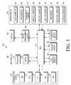
FIG. 8 is an assembled perspective view of an electronic device according to various embodiments of the present disclosure; -
FIG. 9 is an enlarged view of an upper part of a heat radiator according to various embodiments of the present disclosure; -
FIG. 10 is a sectional view of the heat radiator illustrated inFIG. 9 , taken along line A-A'; -
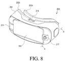
FIG. 11A illustrates another embodiment of a fan cover member according to various embodiments of the present disclosure; -
FIG. 11B is a sectional view of a fan cover member according to another embodiment mounted on a frame according to various embodiments of the present disclosure; -
FIG. 12A illustrates a hole cover mounted on a fan cover member having a through hole according to various embodiments of the present disclosure; -
FIG. 12B is a sectional view of a fan cover with a hole cover, mounted on a frame according to various embodiments of the present disclosure; -
FIG. 13 is a sectional view of a filtering mesh mounted in an electronic device according to various embodiments of the present disclosure; -
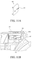
FIG. 14 is a perspective view of a heat diffusion member mounted in at least a part of a device according to various embodiments of the present disclosure; -
FIG. 15 is a perspective view of an electronic device having a heat transfer member in at least a part of a device according to various embodiments of the present disclosure; -
FIG. 16 is a sectional view of an electronic device having a heat transfer member in at least a part of a device according to various embodiments of the present disclosure; -
FIG. 17 is a view illustrating parts of a display, which contact a heat transfer member in a portable electronic device according to various embodiments of the present disclosure; -
FIG. 18 is a view illustrating a first area and a second area that are defined with respect to a lens assembly in a device according to various embodiments of the present disclosure; -
FIG. 19 is a view illustrating a device having a connection hole formed therein according to various embodiments of the present disclosure; -
FIG. 20 is a view illustrating introduction of air into a first area and a second area through a connection hole in an electronic device according to various embodiments of the present disclosure; -
FIG. 21 is a block diagram of a structure for controlling operation of a heat radiator in an electronic device according to various embodiments of the present disclosure; -
FIG. 22 is a block diagram illustrating operating modes of a heat radiator according to input modes of an electronic device according to various embodiments of the present disclosure; -
FIG. 23 is a block diagram illustrating operating modes of a heat radiator according to input modes set for an electronic device according to various embodiments of the present disclosure; -
FIG. 24 is a flowchart illustrating an embodiment of a heat control method in an electronic device according to various embodiments of the present disclosure; -
FIG. 25 is a flowchart illustrating another embodiment of the heat control method in an electronic device according to various embodiments of the present disclosure; and -
FIG. 26 is a flowchart illustrating another embodiment of the heat control method in an electronic device according to various embodiments of the present disclosure. - Throughout the drawings, like reference numerals will be understood to refer to like parts, components, and structures.
- Various embodiments of the present disclosure are described with reference to the accompanying drawings. Various embodiments of the present disclosure can be subject to various modifications and implemented. Specific embodiments are illustrated in the drawings and described in detail. However, the scope of the present disclosure is not intended to be limited to the particular embodiments and it is to be understood that the present disclosure covers all modifications, equivalents, and/or alternatives falling within the scope and spirit of the present disclosure. In relation to a description of the drawings, like reference numerals denote the same components.
- The terms as used in the present disclosure are provided to describe specific embodiments, and are not intended to limit the scope of other embodiments. It is to be understood that singular forms include plural referents unless the context clearly dictates otherwise.
- In the present disclosure, the term "have," "may have," "include," or "may include" signifies the presence of a specific function, operation, or component, not excluding the presence of one or more additional functions, operations, or components. Also, in various embodiments of the present disclosure, the term "have," "may have," "include," or "may include" signifies the presence of a specific feature, number, step, operation, component, or part, or their combination, not excluding the presence or addition of one or more other features, numbers, steps, operations, components, or parts, or a combination thereof.
- In the present disclosure, the term "and/or" may cover all possible combinations of enumerated words. For example, "A and/or B" may represent just A, just B, or both A and B.
- Expressions such as "first" and "second" may modify various components in various embodiments, not limit the components. For example, the expressions do not limit the sequence and/or importance of the components. These expressions are generally to be used to distinguish one component from another component. For example, a first user equipment (UE) and a second UE may be the same UEs or different UEs. Accordingly, a first component may be referred to as a second component and vice versa without departing the scope of the present disclosure.
- When it is said that when a first component is "operatively or communicatively coupled with/to" or "connected to" a second component, it should be understood that the first component is connected to the second component directly or through at least another component. On the other hand, when it is said that a first component is "directly connected to" or "directly coupled to" a second component, it should be understood that there is no other component between the first and second components.
- Unless otherwise defined, the terms and words including technical or scientific terms used in the following description and claims may have the same meanings as generally understood by those skilled in the art. The terms as generally defined in dictionaries may be interpreted as having the same or similar meanings as or to contextual meanings of related technology. Unless otherwise defined, the terms should not be interpreted as ideally or excessively formal meanings.
- An electronic device according to various embodiments of the present disclosure may also be referred to as, for example, a portable electronic device or a device, which is described in the later-described various embodiments of the present disclosure.
- According to various embodiments of the present disclosure, an electronic device may be, for example, a smartphone, a tablet personal computer (PC), a mobile phone, a video phone, an e-book reader, a desktop PC, a laptop PC, a netbook computer, a personal digital assistant (PDA), a portable multimedia player (PMP), an MP3 player, a mobile medical equipment, a camera, and a wearable device (for example, a head-mounted device (HMD) such as electronic glasses, electronic clothes, an electronic bracelet, an electronic necklace, an electronic appcessory, an electronic tattoo, or a smart watch).
- According to some embodiments, an electronic device may be a smart home appliance. For example, the smart home appliance may be at least one of a television (TV), a digital versatile disk (DVD) player, an audio player, a refrigerator, an air conditioner, a vacuum cleaner, an oven, a micro oven, a washer, an air purifier, a set-top box, a TV box (for example, Samsung HomeSync™, Apple TV™, Google TV™, or the like), a game console, an electronic dictionary, an electronic key, a camcorder, and an electronic picture frame.
- According to some embodiments, an electronic device may be at least one of a medical device (for example, a magnetic resonance angiography (MRA) device, a magnetic resonance imaging (MRI) device, a computed tomography (CT) device, an imaging device, an ultrasonic device, or the like), a navigation device, a global positioning system (GPS) receiver, an event data recorder (EDR), a flight data recorder (FDR), an automotive infotainment device, a naval electronic device (for example, a naval navigation device, a gyrocompass, or the like), an avionic electronic device, a security device, an in-vehicle head unit, an industrial or consumer robot, an automatic teller machine (ATM) in a financial facility, and a point of sales (POS) device in a shop.
- According to some embodiments, an electronic device may be at least one of furniture, part of a building/structure, an electronic board, an electronic signature receiving device, a projector, and various measuring devices (for example, water, electricity, gas or electro-magnetic wave measuring devices).
- According to various embodiments, an electronic device may be one or a combination of two or more of the foregoing devices. According to various embodiments, an electronic device may be a flexible device. In addition, it will be apparent to one having ordinary skill in the art that an electronic device according to various embodiments of the present disclosure is not limited to the foregoing devices.
- The term "user" as used in various embodiments of the present disclosure may refer to a person or device (for example, artificial intelligence electronic device) that uses an electronic device. Furthermore, the term "wearer" as used in various embodiments of the present disclosure may refer to a person that wears an HMD on the head and uses content provided by the HMD or an electronic device detachably mounted on the HMD.
-
FIG. 1 illustrates an example in which a portableelectronic device 300 is mounted on adevice 200 according to various embodiments of the present disclosure, andFIG. 2 illustrates an example in which a user wears thedevice 200 with the portableelectronic device 300 mounted thereon according to various embodiments of the present disclosure.FIG. 3 is a perspective view of thedevice 200 taken from a different direction, according to various embodiments of the present disclosure, andFIG. 4 is a perspective view of thedevice 200 taken from the front, according to various embodiments of the present disclosure. - Referring to
FIGS. 1 to 4 , an electronic device of the present disclosure (hereinafter, referred to as an 'HMD') may be thedevice 200 with a display or a transparent/semi-transparent lens and able to physically attach to a portableelectronic device 300. The HMD may be configured to be fixed on the head of a user and selectively implement a user interface (UI). According to an embodiment of the present disclosure, the portableelectronic device 300 having a display may be fixed to thedevice 200 or detachably mounted on thedevice 200. - The HMD of the present disclosure may provide at least one of a see-though function for providing augmented reality (AR) or a see-closed function for providing virtual reality (VR).
- The see-through function may typically refer to, for example, a function for transferring a real external object(s) to the eyes of a user through the display or the transparent/semi-transparent lens and providing the object(s) and/or a virtual object to the user as visual input or as other sensory input. The see-through function may provide the user with additional information about an actually viewed object and images of the object. In another embodiment, additional information may be provided to the user through a hologram without a display or a lens.
- The see-closed function may be provided by means of a separate display. In an embodiment, the HMD may be configured to have two displays placed in front of the eyes of the user, so that the user may view content (a game, a movie, streaming video, a broadcast, or the like) through the displays. The see-closed function may provide the user with a sense of immersion using an independent screen.
- The HMD of the present disclosure may include the portable
electronic device 300, thedevice 200, and aheat radiator 400. - The portable
electronic device 300 may be, for example, a smartphone, a mobile phone, a navigation device, a game device, a TV, a head unit for vehicles, a laptop computer, a tablet computer, a personal media player (PMP), or a personal digital assistant (PDA). The electronic device may be implemented as a pocket-sized portable communication terminal with a radio communication function. According to an embodiment of the present disclosure, the electronic device may be a flexible device or a flexible display. The portableelectronic device 300 may be detachably mounted on thedevice 200 and display a screen according to at least one of a VR operation and a see-through operation. - The
device 200 may have a mountingsurface 212 in at least a part of the periphery of thedevice 200 on which the portableelectronic device 300 is mounted, and thedevice 200 may fit on the face of a user. - The heat radiator 400 (
FIG. 6 ) may be provided in thedevice 200, specifically on a side surface of aframe 202 of thedevice 200. One ormore heat radiators 400 may be provided to remove heat generated by the portableelectronic device 300. - The
device 200 may include theframe 202 and acover 204. - A space or structure for accommodating, for example, the portable
electronic device 300 may be included in theframe 202. Theframe 202 may further include alens assembly 202b (or optical assembly) including twolenses electronic device 300 and the eyes of the user. If the portableelectronic device 300 is mounted on thedevice 200, theconnector 216 may be provided on a side surface of theframe 202 to electrically connect thedevice 200 to the portableelectronic device 300 so that thedevice 200 and the portableelectronic device 300 may interact with each other. Thelens assembly 202b including the twolenses electronic device 300 and the eyes of the user in theframe 202. - An outlet for discharging air introduced in to the
frame 202 through theheat radiator 400 may be provided in at least a part of theframe 202, specifically under theframe 202. The outlet may be formed separately in theframe 202 or a hole formed between theframe 202 and thelens assembly 202b may be used as the outlet. The outlet for discharging air will be described later. - The
frame 202 may be formed of a relatively lightweight material such as, for example, plastic for good wearability. However, the material of theframe 202 is not limited thereto. In another embodiment, the material of theframe 202 may include at least one of various other materials such as, for example, glass, ceramic, a metal such as aluminum, iron, stainless steel (STS), and a metal alloy such as a titanium alloy or a magnesium alloy, for an increased strength or enhanced looks. - The
frame 202 may include, for example, a touch panel as a UI on a part of an outer surface of theframe 202. The touch panel may be provided on the outer surface of theframe 202 so that the positions of one or more displays or the positions of thelenses control device 214 may be provided in theframe 202 to control the portableelectronic device 300. Thecontrol device 214 will be described later. - The
cover 204 is detachably mounted on thedevice 200. If the portableelectronic device 300 is mounted on thedevice 200, thecover 204 may fix the portableelectronic device 300 to thedevice 200. Thecover 204 may cover the periphery of the rear surface of the portableelectronic device 300 to keep the portableelectronic device 300 securely mounted on thedevice 200. - While it is described by way of example that the
cover 204 is provided on one surface of thedevice 200 to keep the portableelectronic device 300 mounted on thedevice 200 in the embodiment of the present disclosure, the present disclosure is not limited thereto. For example, the mountingsurface 212 may be provided on at least a part of thedevice 200 so that the portableelectronic device 300 may be mounted on the mountingsurface 212. If a structure is provided to fixedly support the portableelectronic device 300 at both sides of the mountingsurface 212, thecover 204 may not be needed. - According to an embodiment of the present disclosure, the
frame 202 may include a support member (or 'wearing member') 206, thelens assembly 202b the mountingsurface 212, theconnector 216, aface contact 202a, thecontrol device 214, aposition adjuster 218, and a mounting opening unit 260 (FIG. 6 ). - The
support member 206 may secure thedevice 200 to the user's head. Thesupport member 206 may be, for example, a band formed of an elastic material, eyeglass temples, a helmet, or a strap. Thesupport member 206 may bring theframe 202 into close contact with the area of the face around the eyes of the user. - The
lens assembly 202b includes thelenses frame 202. The wearer may view a screen on a display (not shown) through thelenses lenses face contact 202a, to be described below, so that the user may view the screen of the display, and the other surface of each of thelenses surface 212 so that a screen of the display of the portableelectronic device 300 mounted on the front surface of thedevice 200 may be viewed. - The mounting
surface 212 may recede from at least a part of theframe 202, specifically the front surface of theframe 202, thus providing a space in which the portableelectronic device 300 may fit. The mountingsurface 212 may be a mechanical structure with which to detachably mount the portableelectronic device 300 on thedevice 200. The mountingsurface 212 may be formed of a flexible material or a deformable material such as an elastic material so as to accommodate various portableelectronic devices 300 of different sizes. Since the mountingsurface 212 is formed of a flexible or deformable material, when the portableelectronic device 300 mounted on the mountingsurface 212 is fixed by thecover 204 or a structure securing the portableelectronic device 300, the display of the portableelectronic device 300 may be brought into close contact with the mountingsurface 212 without being scratched or breaking. Theconnector 216 and asupport 217, which will be described later, are provided on the mountingsurface 212 in order to electrically connect the portableelectronic device 300 to thedevice 200 while supporting the portableelectronic device 300 onto the mountingsurface 212. - The
connector 216 may be provided so that when the portableelectronic device 300 is mounted on thedevice 200, theconnector 216 may be connected to aconnection terminal 302 of the portableelectronic device 300 and thus enable communication between thedevice 200 and the portableelectronic device 300. Specifically, theconnector 216 may be disposed at a side of the mountingsurface 212 and fixedly support a side of the portableelectronic device 300 while electrically connecting to theconnection terminal 302 of the portableelectronic device 300, as illustrated inFIG. 4 andFIG. 6 . - The
support 217 may be positioned on theframe 202, specifically at the other side of the mountingsurface 212 from theconnector 216 in order to support the side opposite to theconnection terminal 302 of the portableelectronic device 300, as illustrated inFIG. 4 andFIG. 6 . Therefore, when the portableelectronic device 300 is mounted on the mountingsurface 212, one side of the portableelectronic device 300 may be supported by theconnector 216 in electrical connection to theconnector 216, and the other side of the portableelectronic device 300 may be supported by thesupport 217. - The
face contact 202a is positioned in at least a part of theframe 202, specifically on a rear surface of theframe 202, as illustrated inFIG. 4 . When the user wears the HMD on the face, theface contact 202a contacts the face of the user. Theface contact 202a may be generally shaped to fit the face of a user, and may include a porous, elastic body in at least a part of theface contact 202a so that theface contact 202a may be stably brought into close contact with the face of the user, and may remove moisture caused by heat generated from the user's body. A part of theface contact 202a may include a nose recess that fits over the nose of the user. - The
control device 214 may be installed on a surface of theframe 202, for example, on the outer surface of theframe 202. Thecontrol device 214 may be an adjustment device with which the user adjusts an input for controlling the HMD, for example, the position of the display of the portableelectronic device 300, or an adjustment unit with which the user adjusts the positions of thelenses control device 214 may also be used to control the portableelectronic device 300. For example, thecontrol device 214 may include at least one of a physical key, a physical button, a touch panel, a joystick, a button, a wheel key, and a touch pad. If thecontrol device 214 is configured as a touch panel, thecontrol device 214 may receive a user's touch input. The touch input may be a direct touch input on the touch panel or a hovering input above the touch panel. If thecontrol device 214 is configured as a touch pad, thecontrol device 214 may display a graphical user interface (GUI) for controlling functions of the portableelectronic device 300. For example, a GUI for controlling sound or images may be displayed. - As described before, when the portable
electronic device 300 is mounted on thedevice 200, theconnection terminal 302 of the portableelectronic device 300 may be connected to theconnector 216 of thedevice 200 and thus a touch input received by the touch panel may be transmitted to the portableelectronic device 300. The portableelectronic device 300 may control a function corresponding to the touch input received from the touch panel in response to the touch input. For example, the portableelectronic device 300 may control a sound volume or video play in response to the received touch input. - The
position adjuster 218 may be installed on a surface of theframe 202, for example, on an outer top surface of theframe 202. Theposition adjuster 218 may adjust the position of the display of the portableelectronic device 300 or the positions of thelenses control device 214. - The portable
electronic device 300 may be, for example, a smart phone with a camera installed on its rear surface. The user may mount the portableelectronic device 300 on the mountingsurface 212 of thedevice 200 so that the front of the portableelectronic device 300 where the display is may face thelenses 28 and 210. The user may fix the portableelectronic device 300 to thedevice 200 by covering the portableelectronic device 300 with thecover 204. The user may wear thedevice 200 with the portableelectronic device 300 on his head, as illustrated inFIG. 2 . The user may view a screen on the display of the portableelectronic device 300 through thelenses worn device 200. - The mounting opening unit 260 (
FIG. 6 ) may be provided on a side surface of theframe 202. The heat radiator 400 (FIG. 6 ) may be installed inside the mountingopening unit 260 and thus the mountingopening unit 260 may introduce external air into thedevice 200, specifically theframe 202 along with operation of theheat radiator 400. -
FIG. 5 is a block diagram of adevice 500 according to various embodiments of the present disclosure. - Referring to
FIG. 5 , thedevice 500 may include a micro controller unit (MCU) 510, acommunication module 520, asensor module 530, aninput module 540, aneye tracking module 550, a vibratingmodule 552, anadjustable optics module 554, apower management module 560, and abattery 562. - The
MCU 510 may be a controller of thedevice 500, which controls other components (for example, thecommunication module 520, thesensor module 530, theinput module 540, theeye tracking module 550, the vibratingmodule 552, theadjustable optics module 554, thepower management module 560, and the battery 562) by executing an operating system (OS) or an embedded software program. TheMCU 510 may include a processor and a memory. - The
communication module 520 may perform data transmission and reception between the portableelectronic device 300 and thedevice 500 by electrically connecting the portableelectronic device 300 and thedevice 500 through wired or wireless communication. According to an embodiment, thecommunication module 520 may include a universal serial bus (USB)module 521, aWiFi module 522, a Bluetooth (BT)module 523, a near field communication (NFC)module 524, and a global positioning system (GPS)module 525. According to an embodiment, at least two of theUSB module 521, theWiFi module 522, theBT module 523, theNFC module 524, and theGPS module 525 may be included in a single integrated chip (IC) or IC package. - The
sensor module 530 may measure physical quantities or detect operational states of thedevice 500, and convert the measured or detected information into electric signals. Thesensor module 530 may include at least one of, for example, anaccelerometer 531, agyro sensor 532, ageomagnetic sensor 533, amagnetic sensor 534, aproximity sensor 535, agesture sensor 536, agrip sensor 537, abiometric sensor 538, and anapproach sensor 539. Thedevice 500 may sense movement of the head of the wearer wearing thedevice 500 using at least one of, for example, theaccelerometer 531, thegyro sensor 532, and thegeomagnetic sensor 533. Thedevice 500 may sense whether thedevice 500 is worn using, for example, theproximity sensor 535 or thegrip sensor 537. According to an embodiment, thedevice 500 may sense whether the user wears thedevice 500 by at least one of, for example, infrared (IR) recognition, pressure recognition, and sensing of a variation in capacitance (or a dielectric constant). The gesture sensor 436 may sense a motion of a hand or finger of the user and receive information about the sensed motion as an input of thedevice 500. Thedevice 500 may sense that an object is approaching the user by means of the approach sensor 439. Additionally or alternatively, thesensor module 530 may include a biometric sensor such as an electrical-nose (E-nose) sensor, an electromyography (EMG) sensor, an ElectroEncephaloGram (EEG) sensor, an electrocardiogram (ECG) sensor, an iris sensor, and a finger print sensor, and recognize biometric information about the user using the biometric sensor. Thesensor module 530 may further include a control circuit for controlling one or more sensors included therein. - The
input module 540 may be thecontrol device 214 illustrated inFIG. 1 . Theinput module 540 may include atouch pad 541 and abutton 542. Thetouch pad 541 may operate in at least one of, for example, capacitive, resistive, infrared, and ultrasonic methods. Thetouch pad 541 may further include a control circuit. If thetouch pad 541 is a capacitive type, physical contact or proximity may be recognized. Thetouch pad 541 may further include a tactile layer to thereby provide haptic feedback to the user. Thebutton 542 may include, for example, a physical button, an optical key, or a keypad. - The
power management module 560 may manage power of thedevice 500. While not shown, thepower management module 560 may include a power management integrated circuit (PMIC), a charger IC, and/or a battery fuel gauge. - The PMIC may be loaded in, for example, an IC or a single on chip (SoC) semiconductor. Charging may be wireless or wired. The charger IC may be used in charging a battery and prevent introduction of overvoltage or overcurrent from a charger. According to an embodiment, there may be a charger IC for at least one of wired charging and wireless charging. Wireless charging may be performed, for example, in a magnetic resonance scheme, a magnetic induction scheme, or an electromagnetic wave scheme, and may use additional circuits for wireless charging, such as a coil loop, a resonance circuit, and/or a rectifier.
- The battery fuel gauge may measure, for example, a charge level, a voltage while charging, current, and/or temperature of the
battery 562. Thebattery 562 may include, for example, a rechargeable battery or a solar battery. - The
eye tracking module 550 may track the eyes of the user with at least one of, for example, an electrical oculography (EOG) sensor, a coil system, a dual purkinje system, a bright pupil system, and a dark pupil system. Theeye tracking module 550 may include a micro camera for eye tracking. - The vibrating
module 552 may generate mechanical vibrations from electrical signals. This may be used to notify the user of incoming calls, status updates (e.g. message/email waiting), and the like in place of or in addition to audible and/or visual notices. - The
adjustable optics module 554 may measure an inter-pupil distance (IPD) of the user so that the user may view an image suitable for the user's sight. Thedevice 500 may adjust the distance between the lenses according to the IPD of the user measured by theadjustable optics module 554. Thedevice 500 may transmit the IPD of the user measured by theadjustable optics module 554 to the portableelectronic device 300 so that the display position of a screen may be adjusted on the display of the portableelectronic device 300. - The
MCU 510 may transmit a motion signal sensed through a motion sensor of thesensor module 530 to the portableelectronic device 300. The motion sensor may be at least one of theaccelerometer 531, thegyro sensor 532, and thegeomagnetic sensor 533. - The
MCU 510 may sense that an object is approaching the user and transmit an approach sensing signal to the portableelectronic device 300. TheMCU 510 may measure a direction from which the object is approaching the wearer of thedevice 500 and transmit information indicating the measured direction to the portableelectronic device 300. - An IR sensor, an ultrasonic sensor, a radio frequency (RF) sensor, and/or a space sensor like radar may be used as the
approach sensor 539. The RF sensor may be, for example, a WiSee sensor and/or an AllSee sensor. According to an embodiment, a wireless communication module may be used as theapproach sensor 539. The wireless communication module may be at least one of, for example, theWiFi module 522, theBT module 523, theNFC module 524, and theGPS module 525. If an object is approaching thedevice 500, the object may weaken the received signal strength indication (RSSI) of a wireless communication signal received at the wireless communication module. If the RSSI rapidly drops below a predetermined threshold for a stationary user, theMCU 510 may sense that an object is approaching. Furthermore, theMCU 510 may sense an object-approaching direction from the direction in which the RSSI drops below the predetermined threshold. -
FIG. 6 is an exploded perspective view of a heat radiator in an electronic device according to various embodiments of the present disclosure, andFIG. 7 illustrates air flow generated from theheat radiator 400 in an electronic device according to various embodiments of the present disclosure. When "in theframe 202," "in to theframe 202" or "inside theframe 202" is stated in the present disclosure, it should be understood to mean the "first area" shown inFIGS. 18 and20 . - Referring to
FIGS. 6 and7 , a HMD may be provided with theheat radiator 400. Specifically, theheat radiator 400 may be disposed in thedevice 200, specifically on a side surface of theframe 202. Theheat radiator 400 may help dissipate heat generated by the portableelectronic device 300 by introducing external air in to theframe 202. Theheat radiator 400 may be a fan type with a blade, or a piezo cooler. When theheat radiator 400 is operating, theheat radiator 400 may dissipate the heat discharged from the portableelectronic device 300 by bringing external air in to theframe 202. - Heat from the portable
electronic device 300 may be transferred to the air introduced in to theframe 202 through theheat radiator 400, and then the air may be discharged through an outlet in theframe 202, which may be, for example, on the bottom surface of theframe 202. Accordingly, theheat radiator 400 may control discharge of heat generated by the portableelectronic device 300 by bringing in external air in to theframe 202. Or theheat radiator 400 may control discharge of heat generated by the portableelectronic device 300 by discharging air inside the frame to the outside. That is, the interior of theframe 202 may be heated with heat generated by the portableelectronic device 300 and heated air inside theframe 202 may be discharged to the outside, thus making it more comfortable for the user of thedevice 200. - If air inside the
frame 202 is discharged to the outside, a heat diffusion member 600 (FIG. 14 ) may be installed to more efficiently transfer heat from the portableelectronic device 300 to the air in theframe 202. Theheat diffusion member 600 may be, for example, a graphite sheet, a heat transfer member containing carbon such as graphene, a metal member such as a copper sheet, or a heat transfer member such as a heat pipe or heat sink may be installed. Accordingly, heat transfer members 700 (FIG. 15 ) may be installed in the vicinity of the heat diffusion member 600 (FIG. 14 ) or the air outlet (not shown) to better remove excess heat. - The
heat radiator 400 may include thefan 410, thefan duct 420, and thefan cover member 430. Thefan 410 and thefan duct 420 may be installed in theframe 202, specifically in the mounting opening unit 260 (FIG. 6 ). Thefan 410 may be configured as a blade or a piezo cooler. As thefan 410 operates, thefan 410 sucks air from the outside and supplies the air in to theframe 202, thus controlling cooling of the portableelectronic device 300. - The
fan duct 420 may be provided to surround thefan 410. Thefan duct 420 may be installed on a peripheral surface of the mountingopening unit 260. Thefan cover member 430 may be engaged on the exterior of theframe 202 to guide flow of air from the outside. - The
heat radiator 400 may be on one side of thedevice 200 or both sides of thedevice 200. Various embodiments of the disclosure may place theheat radiator 400 in different parts of theframe 202 according to design and/or implementation needs. -
FIG. 8 is an assembled perspective view of an electronic device according to various embodiments of the present disclosure,FIG. 9 is an enlarged view of an upper part of a heat radiator according to various embodiments of the present disclosure, andFIG. 10 is an enlarged sectional view ofFIG. 8 , taken along line A-A'. - Referring to
FIGS. 8 and9 , theheat radiator 400, including thefan 410 and thefan duct 420, may be accommodated in the mounting opening unit 260 (FIG. 6 ) formed on a side surface of theframe 202, and at least one opening may be formed in the mountingopening unit 260 to allow introduction of air for thefan 410. - The
fan cover member 430 may be provided to cover thefan 410 and thefan duct 420 mounted in the mountingopening unit 260. Thefan cover member 430 may be detachably mounted on the front surface of the mountingopening unit 260 on the outer surface of theframe 202. The size of thefan cover member 430 may be equal to or larger than the size of the mountingopening unit 260. Thefan cover member 430 may fixedly protrude from the surface of thedevice 200, thus forming anair inlet 400a between the periphery of thefan cover member 430 and thedevice 200. As theair inlet 400a is formed along the periphery of thefan cover member 430, theair inlet 400a may prevent direct introduction of external air to thefan 410. Furthermore, thefan cover member 430 may hide thefan 410 from the outside, thus enhancing the design aspect of thedevice 200. -
FIG. 11A illustrates another embodiment of thefan cover member 430, andFIG. 11B is a sectional view of thefan cover member 430 installed in theframe 202 according to various embodiments of the present disclosure. - Referring to
FIGS. 11A and 11B , at least one throughhole 431 may be formed in the surface of thefan cover member 430. The throughhole 431 may be provided to allow more air in to theframe 202. In the present disclosure, a throughhole 431 may be formed in various shapes other than a circle. -
FIG. 12A illustrates ahole cover 432 provided in thefan cover member 430 having the throughhole 431 formed therein according to various embodiments of the present disclosure, andFIG. 12B is a sectional view of thefan cover member 430 with thehole cover 432, mounted on theframe 202 according to various embodiments of the present disclosure. - Referring to
FIGS. 12A and 12B , thehole cover 432 may be provided in thefan cover member 430. Thehole cover 432 may be detachably attached on the throughhole 431, covering the throughhole 431. In an ordinary situation of the HMD, for example, if the temperature of the portableelectronic device 300 is not high or a temperature detection value of a later-describedsecond sensing unit 270 is equal to or lower than a predetermined threshold temperature, thehole cover 432 may be provided to cover the throughhole 431. On the other hand, if the temperature of the portableelectronic device 300 rapidly increases or the temperature detection value of the later-describedsecond sensing unit 270 exceeds a threshold temperature during a normal operation state of thefan 410, the throughhole 431 may be opened by removing thehole cover 432 from thefan cover member 430. As the throughhole 431 is opened by removing thehole cover 432 from thefan cover member 430, more external air may be introduced in to theframe 202. -
FIG. 13 is a sectional view of adustproof mesh 1305 installed in an electronic device according to various embodiments of the present disclosure. - Referring to
FIG. 13 , thedustproof mesh 1305 may be provided before or after thefan 410 and/or thefan duct 420 to restrict introduction of foreign materials. - When the
fan 410 operates and thus external air is introduced in to theframe 202, foreign materials such as external dust may be introduced in to theframe 202. The foreign materials may attach to the surfaces of parts requiring transparency such as thelenses dustproof mesh 1305 may be disposed on at least one surface, for example, a surface before thefan 410 and thefan duct 420, or after thefan 410 and thefan duct 420 in order to filter foreign materials. Thedustproof mesh 1305 may be formed of various materials in various shapes as well as a mesh type. For example, thedustproof mesh 1305 may be formed of, for example, felt through which air passes or a multi-porous elastic material. -
FIG. 14 is a perspective view of theheat diffusion member 600 on at least one surface of thedevice 200 according to various embodiments of the present disclosure. - Referring to
FIG. 14 , theheat diffusion member 600 may be provided in thedevice 200 to receive heat from the portableelectronic device 300 and diffuse the heat. Theheat diffusion member 600 may be provided on a surface of thedevice 200, for example, the mountingsurface 212 on which the portableelectronic device 300 is mounted. That is, if the portableelectronic device 300 is mounted on thedevice 200, a surface may be formed around thelenses electronic device 300 faces the mountingsurface 212. Theheat diffusion member 600 may be provided on a surface on thedevice 200 which the portableelectronic device 300 faces thedevice 200, forward from the mountingsurface 212 to thereby receive heat from the portableelectronic device 300. Theheat diffusion member 600 may be provided to receive heat generated from the portableelectronic device 300 as radiant heat and radiate the heat. Theheat diffusion member 600 may be shaped into '' around one surfaces of the
lenses surface 212. Theheat diffusion member 600 may be formed of a material containing a metal having high heat conductivity such as aluminum, copper, STS, or a carbon-containing material such as graphite, carbon nanotubes, or graphene. - Furthermore, the
heat diffusion member 600 may be formed with a coating such as, for example, diamond like carbon (DLC) coating, plating, or deposition. The heat diffusion member may also comprise, for example, a heat pipe. - The
heat diffusion member 600 may be a part of a front case assembled on the front surface of theframe 202 in thedevice 200. Or the whole front case assembled on theframe 202 may be provided as theheat diffusion member 600 in thedevice 200. For example, the mountingsurface 212 for accommodating the portableelectronic device 300 may be formed to be thermally conductive and heat generated from the portableelectronic device 300 may be transferred to thedevice 200, which may be cooled by air flowing in theframe 202. The thermally conductive material may be, for example, thermally conductive plastic, or metal as mentioned above. -
FIG. 15 is a perspective view of thedevice 200 having theheat transfer members 700 in at least a part of thedevice 200 according to various embodiments of the present disclosure,FIG. 16 is a front sectional view of thedevice 200 having theheat transfer members 700 in at least a part of thedevice 200 according to various embodiments of the present disclosure, andFIG. 17 illustrates a part of the display of the portableelectronic device 300 that contacts theheat transfer members 700 according to various embodiments of the present disclosure. - Referring to
FIGS. 15 ,16 , and17 , the heat transfer member 700s may be provided between theheat diffusion member 600 and the portableelectronic device 300 to transfer heat from the portableelectronic device 300 to theheat diffusion member 600 via conduction. Theheat transfer members 700 may distribute the heat generated from the portableelectronic device 300 faster than the heat is transferred to theheat diffusion member 600 as radiant heat. - The
heat transfer members 700 may be as thick as or thicker than a space between the portableelectronic device 300 and theheat diffusion member 600. If theheat transfer members 700 are thicker than the space, the portableelectronic device 300 and theheat diffusion member 600 may be brought into closer contact. As a consequence, heat may be transferred more readily from the portableelectronic device 300 to theheat diffusion member 600. - The
heat transfer members 700 may be formed of a thermal interface material (TIM), or theheat transfer members 700 may be formed of a cushioning material capable of heat transfer, such as thermally conductive sponge. While it is described in various embodiments of the present disclosure that theheat transfer members 700 are formed of a TIM or thermally conductive sponge, by way of example, the present disclosure is not limited thereto. Theheat transfer members 700 may be formed of any other material that is capable of transferring heat from the portableelectronic device 300 to theheat diffusion member 600. - According to an embodiment of the present disclosure, the
heat transfer members 700 are disposed at the center of theheat diffusion member 600, by way of example. Thus, theheat transfer members 700 may be positioned in an inactive area, between active areas of the display screen of the portableelectronic device 300 facing thelenses - As the
heat transfer members 700 are positioned between thelenses heat transfer members 700 may uniformly distribute heat generated by the portableelectronic device 300 to theheat diffusion member 600. However, the installation position of theheat transfer members 700 is not limited to a specific position. For example, theheat transfer members 700 may be positioned in any area corresponding to the inactive area(s) of a display surface of the portableelectronic device 300. Thus, theheat transfer members 700 may prevent interference with the active display areas. -
FIG. 18 illustrates thedevice 200 divided into a first area and a second area with respect to thelens assembly 202b according to various embodiments of the present disclosure,FIG. 19 illustrates thedevice 200 havingconnection holes 220 according to various embodiments of the present disclosure, andFIG. 20 illustrates introduction of air from the first area to the second area through the connection holes 220 in the electronic device according to various embodiments of the present disclosure. - Referring to
FIGS. 18 ,19 , and20 , thedevice 200 may be divided into the first area and the second area with respect to thelens assembly 202b of theframe 202. The first area may be an area in which air is introduced through theheat radiator 400 in theframe 202, and the second area may be area between the first area and the face of the user. - External air may be introduced into the first area through the
fan 410 of theheat radiator 400 to remove heat generated by the portableelectronic device 300. However, when the user wears the HMD, heat generated by the face of the user may heat air inside the second area, thus causing condensation on the surfaces of thelenses fan 410 operates, the temperature difference between the surface of thelenses lenses lenses lens assembly 202b facing the second area so that the first area and the second area may share air flow with each other. The connection holes 220 may connect the first area to the second area inside theframe 202 so that air flowing in the first area may be introduced into the second area. - The air introduced from the first area to the second area through the connection holes 220 may come out through openings formed on the
face contact 202a that contacts the face of the user. Since air flows to the second area through the connection holes 220, the temperature difference between the first area and the second area may become smaller, and even though the user wears the HMD for a long time, moisture may not condense on the surfaces of thelenses -
FIG. 21 is a block diagram of a structure for controlling operation of theheat radiator 400 in an electronic device according to various embodiments of the present disclosure. - Referring to
FIG. 21 , thedevice 200 may include afirst sensing unit 265, thesecond sensing unit 270, and acontroller 250. Thefirst sensing unit 265 may be provided on thedevice 200, for example, on the surface of theface contact 202a. Thefirst sensing unit 265 may be provided to sense that thedevice 200 with the portableelectronic device 300 mounted thereon is worn on the face of the user. - The
first sensing unit 265 may include a mechanical member such as a switch or a button. Or thefirst sensing unit 265 may include at least one of a proximity sensor, an illumination sensor, and a grip sensor. In an embodiment of the present disclosure, thefirst sensing unit 265 is a proximity sensor, by way of example. When the user wears thedevice 200 on the head, the proximity sensor senses wearing of thedevice 200 on the head of the user. It may be determined whether to operate theheat radiator 400, for example, thefan 410 depending on whether a signal generated from the proximity sensor has been detected. That is, if a signal indicating thedevice 200 is on the head of the user is detected from the proximity sensor, thefan 410 may be operated according to the detection value, and heat generated by thedevice 200 may be dissipated by thefan 410. - While the present disclosure is described in the context that the
heat radiator 400 is operated in response to detection of the proximity sensor, this is purely exemplary and does not limit the present disclosure. Thus, many modifications or variations may be made, for example, like control of operation of theheat radiator 400 according to a detection value of thesecond sensing unit 270 after operation of the proximity sensor, as described below. - The
second sensing unit 270 may be provided in thedevice 200 or the portableelectronic device 300. Thesecond sensing unit 270 may be provided to sense heat generated by the portableelectronic device 300. Thesecond sensing unit 270 may be, for example, a temperature sensor. While thesecond sensing unit 270 is described as being provided in thedevice 200 in an embodiment of the present disclosure, thesecond sensing unit 270 may be provided in the portableelectronic device 300 in order to sense the temperature of the portableelectronic device 300 more accurately. - The
controller 250 may be provided to control operation of theheat radiator 400 according to a detection value sensed in at least one of thefirst sensing unit 265 and thesecond sensing unit 270. Also, thecontroller 250 may be provided to control an operating mode of theheat radiator 400 according to an input mode that has been set. -
FIG. 22 is a block diagram illustrating operating modes of theheat radiator 400 according to detection values of thesecond sensing unit 270 in an electronic device according to various embodiments of the present disclosure. - Referring to
FIG. 22 , theheat radiator 400, specifically thefan 410, may operate at a different speed according to a detection value of thesecond sensing unit 270 according to an embodiment of the present disclosure (seeFIG. 23 ). For example, if a temperature value detected by thesecond sensing unit 270 is equal to or lower than a predetermined threshold temperature T(ref), thecontroller 250 may control operation of thefan 410 in a predetermined first fan operating mode DM1 corresponding to a first fan speed. If the temperature value detected by thesecond sensing unit 270 is higher than the predetermined threshold temperature T(ref), thecontroller 250 may control operation of thefan 410 in a predetermined second fan operating mode DM2 corresponding to a second fan speed, where the second fan speed may be higher than the first fan speed. -
FIG. 23 is a block diagram illustrating operating modes of theheat radiator 400 according to modes of an electronic device that have been set according to various embodiments of the present disclosure. - Referring to
FIG. 23 , theheat radiator 400 may operate at a different speed according to an input mode that has been set, unlike the foregoing embodiment. For example, three input modes, a first mode M1, a second mode M2, and a third mode M3, may be defined so that thefan 410 may operate at three different speeds. If the first mode M1 is selected, thecontroller 250 may control operation of thefan 410 and thefan duct 420 in a normal mode (NM) having a first speed. If the second mode M2 is selected, thecontroller 250 may control operation of thefan 410 and thefan duct 420 in a high quality mode (HQM) having a second speed higher than the first speed. If the third mode M3 is selected, thecontroller 250 may control operation of thefan 410 and thefan duct 420 in a power saving mode (PSM) having a third speed lower than the first speed. - The
heat radiator 400 may be used usually in the NM according to user selection. If theheat radiator 400 is used in the NM, thefan 410 may operate at have the predetermined first speed (in revolutions per minute or RPM). Also, theheat radiator 400 may be used in the PSM according to user selection. If theheat radiator 400 is used in the PSM, less heat may be removed from the portableelectronic device 300 than in the NM, but the heat radiator will also use less power. Also, theheat radiator 400 may be used in the HQM according to user selection. If theheat radiator 400 is used in the HQM, more heat may be removed from the portableelectronic device 300 than in the NM. Depending on the type of thefan 410, more noise may be generated due to the higher RPM of thefan 410 in the HQM. However, removal of more heat may allow a processor intensive VR application may be executed stably. - Operation of the
heat radiator 400 may be controlled according to a detection value of at least one of thefirst sensing unit 265 and thesecond sensing unit 270 in the present disclosure. For example, theheat radiator 400 may be turned on/off according to a detection value of thefirst sensing unit 265 as described in more detail below with respect toFIG. 24 . Or theheat radiator 400 may be turned on/off according to a detection value of thesecond sensing unit 270 as described in more detail below with respect toFIG. 25 . Or theheat radiator 400 may be turned on/off according to detection values of thefirst sensing unit 265 and thesecond sensing unit 270 as described in more detail below with respect toFIG. 26 . -
FIG. 24 is a flowchart illustrating an embodiment of a heat control method in an electronic device according to various embodiments of the present disclosure. - Referring to
FIG. 24 , the heat control method may include determining whether a user is wearing thedevice 200 with the portableelectronic device 300 mounted thereon, and the portableelectronic device 300 displaying a screen according to at least one of a VR operation and a see-through operation (S110). Depending upon whether the user is wearing thedevice 200, theheat radiator 400 installed in thedevice 200 may be turned on to remove heat from the portable electronic device 300 (S210 or S220). - That is, the
device 200 determines whether the user is wearing thedevice 200 through thefirst sensing unit 265 in operation S110. Then, thedevice 200 operates theheat radiator 400 by turning on theheat radiator 400 in operation S210 if thefirst sensing unit 265 indicates thedevice 200 is being worn by the user, or turns off theheat radiator 400 in operation S220 if thefirst sensing unit 265 indicates thedevice 200 is not being worn by the user. - While not shown, the heat control method may further include detecting the temperature of the
device 200 through thesecond sensing unit 270 after determining whether the user is wearing thedevice 200. As described before with reference toFIG. 23 , if a detection value sensed by thesecond sensing unit 270 is equal to or smaller than a predetermined threshold, theheat radiator 400 may operate in the first fan operating mode DM1. If the detection value sensed by thesecond sensing unit 270 is larger than the predetermined threshold, theheat radiator 400 may operate in the second fan operating mode DM2, which is faster than the first fan operating mode DM1. - Furthermore, if the
heat radiator 400 is turned on, the operating speed of theheat radiator 400 may be different according to an input mode which has been set, as illustrated inFIG. 23 . For example, if the first mode M1 is selected, thefan 410 and thefan duct 420 may operate in the NM having the first speed. If the second mode M2 is selected, thefan 410 and thefan duct 420 may operate in the HQM having the second speed higher than the first speed. If the third mode M3 is selected, thefan 410 and thefan duct 420 may operate in the PSM having the third speed lower than the first speed. -
FIG. 25 is a flowchart illustrating another embodiment of the heat control method in an electronic device according to various embodiments of the present disclosure. - Referring to
FIG. 25 , the heat control method may include detecting the temperature of the portableelectronic device 300 displaying a screen according to at least one of a VR operation and a see-through operation, mounted on the first electronic device or the device 200 (S120 and S130), and operating theheat radiator 400 installed in thedevice 200 to remove heat from the portableelectronic device 300 according to the temperature (S230 or S240). - That is, when the
second sensing unit 270 is operated (S120), thedevice 200 detects the temperature of the portableelectronic device 300 through thesecond sensing unit 270 and compares the detected temperature with a predetermined threshold (S130). If the temperature detected by thesecond sensing unit 270 is equal to or lower than the threshold temperature T(ref), theheat radiator 400 is turned on. Theheat radiator 400 may be turned on to operate in the first fan operating mode DM1 (S230). If the temperature detected by thesecond sensing unit 270 is higher than the temperature T(ref), theheat radiator 400 is turned on. Theheat radiator 400 may be turned on to operate in the second fan operating mode DM2 (S240). -
FIG. 26 is a flowchart illustrating another embodiment of the heat control method in an electronic device according to various embodiments of the present disclosure. - Referring to
FIG. 26 , the heat control method may include determining whether a user wears thedevice 200 with the portableelectronic device 300 mounted thereon around the face of the user, the portableelectronic device 300 displaying a screen according to at least one of a VR operation and a see-through operation (S110), detecting the temperature of the portableelectronic device 300 according to operation of the portable electronic device 300 (S120 and S130), and operating theheat radiator 400 installed in thedevice 200 to remove heat from the portable electronic device 300 (S210, S230, and S240). - That is, the
device 200 determines whether the user is wearing thedevice 200 through the first sensing unit 265 (S110). Then, thedevice 200 operates theheat radiator 400 by turning on theheat radiator 400 according to a detection value of the first sensing unit 265 (S210) or turns off theheat radiator 400 according to the detection value of the first sensing unit 265 (S220). - When the
heat radiator 400 is operating (S210), thesecond sensing unit 270 may detect the temperature of the device 200 (S120). As described before with reference toFIG. 22 , if a detection value sensed by thesecond sensing unit 270 is equal to or smaller than a predetermined threshold temperature T(ref) (S130), theheat radiator 400 may operate in the first fan operating mode DM1 (S230). If the detection value sensed by thesecond sensing unit 270 is larger than the predetermined threshold temperature T(ref), theheat radiator 400 may operate in the second fan operating mode DM2 (S240), which is faster than in the first fan operating mode DM1. - The operating speed of the
heat radiator 400 may be different according to an input mode which has been set, as illustrated inFIG. 23 . For example, if the first mode M1 is selected, thefan 410 and thefan duct 420 may operate in the NM having the first speed. If the second mode M2 is selected, thefan 410 and thefan duct 420 may operate in the HQM having the second speed higher than the first speed. If the third mode M3 is selected, thefan 410 and thefan duct 420 may operate in the PSM having the third speed lower than the first speed. - As is apparent from the foregoing description, an electronic device according to various embodiments of the present disclosure efficiently removes heat generated during operation of an HMD. Thus, a wearer can have stable operation of the HMD.
- According to various embodiments of the present disclosure, the electronic device moves some of the external air introduced into a first area by a heat radiator to a second area inward toward the user from the first area. Therefore, the temperature difference between the first area and the second area can be lessened and condensation on the surfaces of lenses provided in the HMD can be alleviated.
- According to various embodiments of the present disclosure, the electronic device can control operation of the heat radiator according to the user wearing the HMD or the temperature of the electronic device sensed by a sensing unit.
- While the disclosure has been shown and described with reference to certain exemplary embodiments, it will be understood by those skilled in the art that various changes in form and details may be made to those embodiments without departing from the spirit and scope of the disclosure as defined by the appended claims and their equivalents.
Claims (15)
- An electronic device comprising:a frame including at least one optical assembly and a structure configured to receive a portable electronic device including a display, wherein an image is on the display can be seen through the at least one optical assembly when the portable electronic device is in the structure;a wearing member connected to the frame and configured to be worn together with the frame on a head of a user; anda heat radiator configured to remove heat from a space between the display and the optical assembly to outside the electronic device.
- The electronic device of claim 1, wherein the heat radiator comprises a fan, and wherein the frame comprises a mounting opening unit in which the fan is mounted, and the fan is configured to introduce air from outside the electronic device in to the frame or discharge air in the frame to outside the electronic device.
- The electronic device of claim 2, wherein the heat radiator further comprises:a fan duct surrounding the fan; anda fan cover member detachably mounted to cover the mounting opening unit.
- The electronic device of claim 3, wherein the fan cover member substantially covers the mounting opening unit, and wherein an air inlet is formed between a periphery of the fan cover member and the electronic device by the fan cover member being over a surface of the electronic device.
- The electronic device of claim 3, wherein at least one through hole is formed in the fan cover member, and wherein the fan cover member further comprises a hole cover detachably mounted on the fan cover member to cover the through hole.
- The electronic device of claim 2, wherein a filter is further included to filter air drawn in by the fan.
- The electronic device of claim 1, wherein the heat radiator comprises a heat diffusion member.
- The electronic device of claim 7, wherein the heat diffusion member is inserted into a part of a front case provided on a front surface of the frame or is the front case.
- The electronic device of claim7, further comprising a heat transfer member between the heat diffusion member and the portable electronic device, for transferring heat from the portable electronic device to the heat diffusion member, and
wherein the heat transfer member is disposed in at least one of: a center of the heat diffusion member and in an inactive area of a screen of the portable electronic device. - The electronic device of claim 1, wherein when the electronic device is worn on a head of the user, the heat radiator is configured to generate an air flow from at least a part of a space between the optical assembly and eyes of the user, and wherein a connection hole is formed for air flow to the space between the optical assembly and the eyes of the user.
- The electronic device of claim 1, further comprising a proximity sensor, wherein when the portable electronic device is received in the structure, the heat radiator is configured to operate in response to a signal from the proximity sensor.
- The electronic device of claim 11, further comprising a controller configured to control operation of the heat radiator in response to the signal from the proximity sensor, and wherein the controller is configured to control an operating mode of the heat radiator according to an input mode that has been set.
- The electronic device of claim 12, wherein the heat radiator comprises a fan, and wherein the controller is configured to control the fan to operate in at least one of: a normal mode for operating the fan at a first speed, a high quality mode for operating the fan at a second speed faster than the first speed, and a power saving mode for operating the fan at a third speed slower than the first speed.
- The electronic device of claim 13, wherein a signal is provided to the controller by at least one of: the portable electronic device and a temperature sensor included in the electronic device, and wherein the temperature sensor is configured to sense heat generated from the portable electronic device.
- The electronic device of claim 14, wherein if a detection value corresponding to the signal is equal to or smaller than a predetermined threshold, the controller controls the fan to rotate in a first fan operating mode, and if the detection value corresponding to the signal from the temperature sensor is larger than the predetermined threshold, the controller controls the fan to rotate in a second fan operating mode in which the fan rotates faster than in the first fan operating mode.
Applications Claiming Priority (1)
| Application Number | Priority Date | Filing Date | Title |
|---|---|---|---|
| KR1020150028640A KR102439993B1 (en) | 2015-02-27 | 2015-02-27 | Electronic device having heat radiating apparatus and controling method thereof |
Publications (3)
| Publication Number | Publication Date |
|---|---|
| EP3070511A2 true EP3070511A2 (en) | 2016-09-21 |
| EP3070511A3 EP3070511A3 (en) | 2017-01-11 |
| EP3070511B1 EP3070511B1 (en) | 2018-03-14 |
Family
ID=55699315
Family Applications (1)
| Application Number | Title | Priority Date | Filing Date |
|---|---|---|---|
| EP16157122.9A Active EP3070511B1 (en) | 2015-02-27 | 2016-02-24 | Electronic device having heat radiator and method for controlling the electronic device |
Country Status (4)
| Country | Link |
|---|---|
| US (1) | US9839166B2 (en) |
| EP (1) | EP3070511B1 (en) |
| KR (1) | KR102439993B1 (en) |
| CN (1) | CN105934134B (en) |
Cited By (4)
| Publication number | Priority date | Publication date | Assignee | Title |
|---|---|---|---|---|
| RU172721U1 (en) * | 2017-01-16 | 2017-07-21 | Александр Владимирович Золин | Augmented Reality Glasses |
| WO2018132031A1 (en) * | 2017-01-16 | 2018-07-19 | Александр Владимирович ЗОЛИН | Augmented reality glasses |
| EP3392690A1 (en) * | 2017-04-19 | 2018-10-24 | Oculus VR, LLC | System for discharging heat out of head-mountend display based on hybrid fan and heat pipe |
| EP3757643A1 (en) * | 2019-06-28 | 2020-12-30 | Valeo Comfort and Driving Assistance | Head-up display |
Families Citing this family (90)
| Publication number | Priority date | Publication date | Assignee | Title |
|---|---|---|---|---|
| US9420075B2 (en) | 2014-07-16 | 2016-08-16 | DODOcase, Inc. | Virtual reality viewer and input mechanism |
| US20160127716A1 (en) * | 2014-10-29 | 2016-05-05 | Juan Carlos Ramiro | Virtual reality underwater mask |
| KR102524322B1 (en) * | 2015-09-25 | 2023-04-24 | 삼성전자주식회사 | Band connecting device and head-mounted display apparatus having the same |
| US20170184863A1 (en) * | 2015-12-24 | 2017-06-29 | Sulon Technologies Inc. | Cooling system for head mounted device |
| JP2017195514A (en) * | 2016-04-20 | 2017-10-26 | キヤノン株式会社 | Head mount device and gripping device |
| CN106019597A (en) * | 2016-07-27 | 2016-10-12 | 北京小米移动软件有限公司 | Virtual reality glasses |
| KR20180013009A (en) * | 2016-07-28 | 2018-02-07 | 삼성전자주식회사 | Interface connector device including compatible gender |
| CN106132169A (en) * | 2016-08-16 | 2016-11-16 | 青岛歌尔声学科技有限公司 | A kind of wear-type virtual reality device |
| WO2018049622A1 (en) * | 2016-09-14 | 2018-03-22 | 深圳市柔宇科技有限公司 | Head-mounted display apparatus and eye patch thereof |
| TWI605329B (en) * | 2016-09-22 | 2017-11-11 | 建準電機工業股份有限公司 | Head wearable display device |
| US10095461B2 (en) * | 2016-09-23 | 2018-10-09 | Intel IP Corporation | Outside-facing display for head-mounted displays |
| US10168798B2 (en) * | 2016-09-29 | 2019-01-01 | Tower Spring Global Limited | Head mounted display |
| CN106646871B (en) * | 2016-10-20 | 2024-03-12 | 深圳纳德光学有限公司 | Head-mounted display with heat radiation system |
| CN108108011A (en) * | 2016-11-24 | 2018-06-01 | 京东方科技集团股份有限公司 | A kind of virtual reality all-in-one machine |
| CN107995957B (en) * | 2016-12-29 | 2021-01-12 | 深圳市柔宇科技有限公司 | Head-mounted display device |
| US10437343B2 (en) * | 2017-01-06 | 2019-10-08 | Samsung Electronics Co., Ltd. | Augmented reality control of internet of things devices |
| CN106873183A (en) * | 2017-01-17 | 2017-06-20 | 上海电力学院 | Multifunctional 3 D glasses |
| CN106852076B (en) * | 2017-01-23 | 2019-06-04 | 昆山国显光电有限公司 | A kind of radiator structure and the VR glasses using it |
| CN106932905A (en) * | 2017-02-27 | 2017-07-07 | 阿里巴巴集团控股有限公司 | Virtual reality helmet |
| CN106950695A (en) * | 2017-03-31 | 2017-07-14 | 谢亦瞻 | A kind of VR glasses |
| US11494986B2 (en) * | 2017-04-20 | 2022-11-08 | Samsung Electronics Co., Ltd. | System and method for two dimensional application usage in three dimensional virtual reality environment |
| US10261555B1 (en) * | 2017-04-28 | 2019-04-16 | Google Llc | Airflow in augmented and/or virtual reality head mounted display device |
| US11366491B2 (en) * | 2017-05-04 | 2022-06-21 | Htc Corporation | Head-mounted display device |
| TWI624707B (en) * | 2017-05-18 | 2018-05-21 | Syndiant Inc | Double-eye head-mounted device with a distance adjustment mechanism |
| IL303933B1 (en) * | 2017-05-30 | 2024-04-01 | Magic Leap Inc | Power supply assembly with fan assembly for electronic device |
| CN107238930A (en) | 2017-07-19 | 2017-10-10 | 北京小米移动软件有限公司 | Virtual reality glasses |
| TWI626473B (en) * | 2017-07-25 | 2018-06-11 | 廣達電腦股份有限公司 | Head-mounted display |
| US11138915B2 (en) | 2017-07-28 | 2021-10-05 | Magic Leap, Inc. | Fan assembly for displaying an image |
| US10579114B1 (en) | 2017-08-15 | 2020-03-03 | Facebook Technologies, Llc | Heat dissipating assembly for head-mounted displays |
| US10492346B2 (en) | 2017-09-07 | 2019-11-26 | Apple Inc. | Thermal regulation for head-mounted display |
| US10405467B2 (en) * | 2017-09-29 | 2019-09-03 | Google Llc | Integrated thermal door component for head mounted display |
| US10416735B2 (en) * | 2017-10-10 | 2019-09-17 | Google Llc | Heat pipe thermal component for cooling system |
| CN107949236B (en) * | 2017-10-27 | 2019-09-27 | 中国船舶重工集团公司第七二三研究所 | A kind of synthesis heat-exchanger rig based on conduction |
| CN107656373A (en) * | 2017-11-08 | 2018-02-02 | 深圳创维新世界科技有限公司 | visual device |
| CN107703635A (en) * | 2017-11-17 | 2018-02-16 | 重庆创通联达智能技术有限公司 | A kind of VR glasses and its radiator structure |
| CN108125679A (en) * | 2017-12-22 | 2018-06-08 | 玉林市玉州区万通华信科技服务部 | A kind of portable cardiac electric data sampler |
| FR3077650A1 (en) * | 2018-02-05 | 2019-08-09 | Valeo Comfort And Driving Assistance | HIGH HEAD DISPLAY FOR MOTOR VEHICLE |
| KR102580702B1 (en) * | 2018-02-22 | 2023-09-20 | 삼성전자주식회사 | Electronic device including moisture inducing structure |
| TWI658683B (en) * | 2018-02-22 | 2019-05-01 | 宏碁股份有限公司 | Head mount display |
| CN108650367B (en) * | 2018-04-20 | 2020-08-04 | 歌尔科技有限公司 | Cell-phone fixture and wear product |
| US20190354148A1 (en) * | 2018-05-17 | 2019-11-21 | Microsoft Technology Licensing, Llc | Conducting heat through a hinge |
| KR102090094B1 (en) * | 2018-05-23 | 2020-03-17 | 주식회사 브이알이지이노베이션 | VR Headset Device Providing Wide Viewing Angle |
| US11076510B2 (en) * | 2018-08-13 | 2021-07-27 | Facebook Technologies, Llc | Heat management device and method of manufacture |
| KR102619540B1 (en) * | 2018-08-20 | 2023-12-29 | 주식회사 테그웨이 | Feedback device and method for providing thermal using the same |
| JP7042194B2 (en) * | 2018-08-31 | 2022-03-25 | 株式会社日立エルジーデータストレージ | Image projection optical module and head-mounted display |
| CN112740136A (en) * | 2018-09-26 | 2021-04-30 | 索尼公司 | Temperature control device, garment, and attachment aid |
| TWI735906B (en) * | 2018-10-08 | 2021-08-11 | 宏達國際電子股份有限公司 | Head-mounted display device |
| CN109358424B (en) * | 2018-10-23 | 2020-12-04 | 重庆工程学院 | Be suitable for VR equipment of wearing in motion |
| CN110720073B (en) * | 2018-10-30 | 2022-03-25 | 深圳市大疆创新科技有限公司 | Head-mounted electronic equipment |
| US10823969B1 (en) | 2018-12-14 | 2020-11-03 | Google Llc | Heat transfer through frame component of head-mounted device |
| KR102424311B1 (en) * | 2019-03-27 | 2022-07-22 | 다보(주) | Telescope type viewing system having mobile device for augmented reality |
| US11758702B2 (en) * | 2019-04-30 | 2023-09-12 | Apple Inc. | Noise mitigation for head-mounted device |
| US10579111B1 (en) * | 2019-05-03 | 2020-03-03 | Facebook Technologies, Llc | Heat management device for eyecup assemblies of head mounted displays |
| CN110376745A (en) * | 2019-07-30 | 2019-10-25 | 华育昌(肇庆)智能科技研究有限公司 | Convenient for the VR glasses of heat dissipation |
| CN110376746B (en) * | 2019-08-01 | 2021-09-07 | 华育昌(肇庆)智能科技研究有限公司 | VR glasses |
| CN110471183A (en) * | 2019-08-06 | 2019-11-19 | 衡振兴 | A kind of Virtual Reality glasses with massage functions |
| CN110716308A (en) * | 2019-09-06 | 2020-01-21 | 华为技术有限公司 | Face guard and head-mounted display device |
| TWI723613B (en) * | 2019-11-04 | 2021-04-01 | 宏星技術股份有限公司 | Head-mounted display |
| CN111356339B (en) * | 2020-02-28 | 2022-02-08 | 上海天马微电子有限公司 | Vehicle-mounted heat dissipation system and heat dissipation method |
| US11860444B2 (en) | 2020-04-15 | 2024-01-02 | Apple Inc. | Electronic devices with covering structures |
| US11910568B2 (en) * | 2020-04-20 | 2024-02-20 | Cisco Technology, Inc. | Heat dissipation system with microelectromechanical system (MEMS) for cooling electronic or photonic components |
| US11815693B2 (en) | 2020-04-20 | 2023-11-14 | Apple Inc. | Head-mounted electronic device |
| US11737218B2 (en) * | 2020-06-09 | 2023-08-22 | Htc Corporation | Head-mounted display device |
| CN213218179U (en) * | 2020-06-15 | 2021-05-18 | 深圳北极之光科技有限公司 | Electronic goggles structure |
| CN111770666B (en) * | 2020-06-30 | 2021-11-30 | 歌尔科技有限公司 | Head-mounted device, heat dissipation method thereof, and computer-readable storage medium |
| US11762422B1 (en) * | 2020-07-06 | 2023-09-19 | Apple Inc. | Electronic devices with drop protection |
| TWM604890U (en) * | 2020-08-10 | 2020-12-01 | 和碩聯合科技股份有限公司 | Electronic device |
| CN112099238B (en) * | 2020-10-30 | 2022-07-08 | 歌尔光学科技有限公司 | Head-mounted display equipment and front end air cooling heat dissipation structure thereof |
| US11513573B2 (en) * | 2020-11-09 | 2022-11-29 | Meta Platforms Technologies, Llc | Active thermal management of a display panel |
| CN112291977B (en) * | 2020-11-13 | 2022-12-27 | Oppo广东移动通信有限公司 | Main body device of head-mounted equipment and head-mounted equipment |
| CN112505923B (en) * | 2020-11-13 | 2023-03-21 | Oppo广东移动通信有限公司 | Mainboard and head-mounted equipment |
| US11874471B2 (en) | 2020-11-23 | 2024-01-16 | Samsung Electronics Co., Ltd. | Electronic device including heat radiating member |
| CN112433378A (en) * | 2020-12-02 | 2021-03-02 | 陈姣娇 | Immersive display device based on 3D animation design |
| CN116848957A (en) | 2021-02-03 | 2023-10-03 | 三星电子株式会社 | Wearable electronic device comprising heat dissipation structure |
| EP4288856A1 (en) | 2021-02-08 | 2023-12-13 | Sightful Computers Ltd | Extended reality for productivity |
| EP4288950A1 (en) | 2021-02-08 | 2023-12-13 | Sightful Computers Ltd | User interactions in extended reality |
| EP4295314A1 (en) | 2021-02-08 | 2023-12-27 | Sightful Computers Ltd | Content sharing in extended reality |
| WO2023009580A2 (en) | 2021-07-28 | 2023-02-02 | Multinarity Ltd | Using an extended reality appliance for productivity |
| US11782281B2 (en) * | 2021-07-30 | 2023-10-10 | Meta Platforms Technologies, Llc | Thermal management system for electronic device |
| US11698536B2 (en) * | 2021-07-30 | 2023-07-11 | Meta Platforms Technologies, Llc | Thermal management system for electronic device |
| CN114200677B (en) * | 2021-12-16 | 2023-04-11 | 南京奇元科技有限公司 | A circulation heat abstractor for wear-type VR equipment |
| US11586283B1 (en) * | 2021-12-22 | 2023-02-21 | Meta Platforms Technologies, Llc | Artificial reality device headset DONN and DOFF detection |
| WO2023140222A1 (en) * | 2022-01-24 | 2023-07-27 | 株式会社ソニー・インタラクティブエンタテインメント | Head-mounted display |
| US11948263B1 (en) | 2023-03-14 | 2024-04-02 | Sightful Computers Ltd | Recording the complete physical and extended reality environments of a user |
| US20230334795A1 (en) | 2022-01-25 | 2023-10-19 | Multinarity Ltd | Dual mode presentation of user interface elements |
| US11762208B1 (en) * | 2022-03-31 | 2023-09-19 | Lenovo Global Technology (United States) Inc. | Cooling a virtual reality headset |
| US20230400897A1 (en) * | 2022-06-08 | 2023-12-14 | Motorola Mobility Llc | Wearable Electronic Device with Thermal Energy Transfer System and Corresponding Methods |
| WO2024034833A1 (en) * | 2022-08-12 | 2024-02-15 | 삼성전자주식회사 | Electronic device comprising structure for dissipating heat to outside |
| WO2024048902A1 (en) * | 2022-08-29 | 2024-03-07 | 삼성전자주식회사 | Electronic device comprising heat pipe surrounding multiple integrated circuits |
| WO2024058459A1 (en) * | 2022-09-13 | 2024-03-21 | 삼성전자주식회사 | Electronic device and method for dissipating heat from plurality of heat sources |
Family Cites Families (18)
| Publication number | Priority date | Publication date | Assignee | Title |
|---|---|---|---|---|
| DE3046046A1 (en) * | 1980-12-06 | 1982-07-15 | Uvex Winter Optik GmbH, 8510 Fürth | Ventilation system for ski goggles - has battery-driven fan blowing air through goggles when skier stops |
| JPH06175066A (en) * | 1992-12-07 | 1994-06-24 | Yaskawa Electric Corp | Method and device for cooling head part of helmet for video display device |
| JPH0915527A (en) * | 1995-06-27 | 1997-01-17 | Olympus Optical Co Ltd | Head-mounted video display device |
| JPH1184310A (en) * | 1997-09-16 | 1999-03-26 | Sony Corp | Optical visual sensation device |
| JP2000193910A (en) * | 1998-10-20 | 2000-07-14 | Matsushita Electric Works Ltd | Display device |
| KR100873143B1 (en) * | 2007-04-20 | 2008-12-09 | 엘지전자 주식회사 | Cooling device and virtual image optical system comprising the same |
| US8605008B1 (en) | 2007-05-04 | 2013-12-10 | Apple Inc. | Head-mounted display |
| US8957835B2 (en) * | 2008-09-30 | 2015-02-17 | Apple Inc. | Head-mounted display apparatus for retaining a portable electronic device with display |
| WO2010062481A1 (en) * | 2008-11-02 | 2010-06-03 | David Chaum | Near to eye display system and appliance |
| CN101799585A (en) * | 2010-03-25 | 2010-08-11 | 杨鲁新 | Portable stereoscopic image player |
| KR101431366B1 (en) * | 2010-07-20 | 2014-08-19 | 엠파이어 테크놀로지 디벨롭먼트 엘엘씨 | Augmented reality proximity sensing |
| KR101958778B1 (en) * | 2012-08-31 | 2019-03-15 | 엘지전자 주식회사 | A Head Mounted Display and a Method for Controlling a Digital Device Using the Same |
| KR20140078237A (en) * | 2012-12-17 | 2014-06-25 | (주)이재경스튜디오 | Head mounted display |
| JP2014153578A (en) * | 2013-02-11 | 2014-08-25 | Nippon Seiki Co Ltd | Head-up display |
| US20140333773A1 (en) * | 2013-05-11 | 2014-11-13 | Randy James Davis | Portable audio/ video mask |
| DE202013102458U1 (en) | 2013-06-07 | 2013-07-03 | Stefan Welker | Carrying device for an electronic display device |
| KR102086511B1 (en) * | 2013-07-25 | 2020-03-09 | 엘지전자 주식회사 | Head Mounted Display and controlling method thereof |
| DE202014006891U1 (en) * | 2014-07-02 | 2014-10-22 | Christian Stroetmann | data glasses |
-
2015
- 2015-02-27 KR KR1020150028640A patent/KR102439993B1/en active IP Right Grant
-
2016
- 2016-02-24 EP EP16157122.9A patent/EP3070511B1/en active Active
- 2016-02-25 US US15/053,439 patent/US9839166B2/en active Active
- 2016-02-29 CN CN201610112111.0A patent/CN105934134B/en active Active
Non-Patent Citations (1)
| Title |
|---|
| None |
Cited By (8)
| Publication number | Priority date | Publication date | Assignee | Title |
|---|---|---|---|---|
| RU172721U1 (en) * | 2017-01-16 | 2017-07-21 | Александр Владимирович Золин | Augmented Reality Glasses |
| WO2018132031A1 (en) * | 2017-01-16 | 2018-07-19 | Александр Владимирович ЗОЛИН | Augmented reality glasses |
| EP3392690A1 (en) * | 2017-04-19 | 2018-10-24 | Oculus VR, LLC | System for discharging heat out of head-mountend display based on hybrid fan and heat pipe |
| US10379583B2 (en) | 2017-04-19 | 2019-08-13 | Facebook Technologies, Llc | System for discharging heat out of head-mounted display based on hybrid fan and heat pipe |
| US10656690B2 (en) | 2017-04-19 | 2020-05-19 | Facebook Technologies, Llc | System for discharging heat out of head-mounted display based on hybrid fan and heat pipe |
| US11029730B2 (en) | 2017-04-19 | 2021-06-08 | Facebook Technologies, Llc | System for discharging heat out of head-mounted display based on hybrid fan |
| US11435784B2 (en) | 2017-04-19 | 2022-09-06 | Meta Platforms Technologies, Llc | System for discharging heat out of head-mounted display |
| EP3757643A1 (en) * | 2019-06-28 | 2020-12-30 | Valeo Comfort and Driving Assistance | Head-up display |
Also Published As
| Publication number | Publication date |
|---|---|
| KR102439993B1 (en) | 2022-09-06 |
| EP3070511A3 (en) | 2017-01-11 |
| KR20160105228A (en) | 2016-09-06 |
| EP3070511B1 (en) | 2018-03-14 |
| CN105934134A (en) | 2016-09-07 |
| CN105934134B (en) | 2019-12-31 |
| US20160255748A1 (en) | 2016-09-01 |
| US9839166B2 (en) | 2017-12-05 |
Similar Documents
| Publication | Publication Date | Title |
|---|---|---|
| EP3070511B1 (en) | Electronic device having heat radiator and method for controlling the electronic device | |
| US10292134B2 (en) | Method and apparatus for providing notification | |
| US10607323B2 (en) | Head-mounted electronic device | |
| CN106802482B (en) | Coupler and head-mounted display device | |
| KR102229890B1 (en) | Method for processing data and an electronic device thereof | |
| US10535320B2 (en) | Head-mounted display apparatus | |
| US10028227B2 (en) | Mobile terminal and motion-based low power implementing method thereof | |
| EP2990852B1 (en) | Head-mounted display hosting a smartphone for providing virtual reality environment | |
| US20150382321A1 (en) | Method and apparatus for providing notification | |
| EP3122026B1 (en) | System comprising a mobile terminal and method for controlling the same | |
| US20160063767A1 (en) | Method for providing visual reality service and apparatus for the same | |
| US11445475B2 (en) | Method and apparatus for providing notification | |
| KR20160024168A (en) | Method for controlling display in electronic device and the electronic device | |
| US20160140887A1 (en) | Wearable electronic device | |
| KR102400383B1 (en) | Method for obtaining sensor data and Electronic device using the same | |
| US20160357250A1 (en) | Wearable device having control panel | |
| US10860117B2 (en) | Method for displaying object and electronic device thereof | |
| KR20180013009A (en) | Interface connector device including compatible gender | |
| KR20170025606A (en) | Mobile terminal and operating method thereof |
Legal Events
| Date | Code | Title | Description |
|---|---|---|---|
| PUAI | Public reference made under article 153(3) epc to a published international application that has entered the european phase |
Free format text: ORIGINAL CODE: 0009012 |
|
| AK | Designated contracting states |
Kind code of ref document: A2 Designated state(s): AL AT BE BG CH CY CZ DE DK EE ES FI FR GB GR HR HU IE IS IT LI LT LU LV MC MK MT NL NO PL PT RO RS SE SI SK SM TR |
|
| AX | Request for extension of the european patent |
Extension state: BA ME |
|
| PUAL | Search report despatched |
Free format text: ORIGINAL CODE: 0009013 |
|
| AK | Designated contracting states |
Kind code of ref document: A3 Designated state(s): AL AT BE BG CH CY CZ DE DK EE ES FI FR GB GR HR HU IE IS IT LI LT LU LV MC MK MT NL NO PL PT RO RS SE SI SK SM TR |
|
| AX | Request for extension of the european patent |
Extension state: BA ME |
|
| RIC1 | Information provided on ipc code assigned before grant |
Ipc: G02B 27/01 20060101AFI20161206BHEP Ipc: H05K 5/00 20060101ALI20161206BHEP Ipc: G02C 11/08 20060101ALI20161206BHEP Ipc: H05K 7/20 20060101ALI20161206BHEP |
|
| STAA | Information on the status of an ep patent application or granted ep patent |
Free format text: STATUS: REQUEST FOR EXAMINATION WAS MADE |
|
| 17P | Request for examination filed |
Effective date: 20170412 |
|
| RBV | Designated contracting states (corrected) |
Designated state(s): AL AT BE BG CH CY CZ DE DK EE ES FI FR GB GR HR HU IE IS IT LI LT LU LV MC MK MT NL NO PL PT RO RS SE SI SK SM TR |
|
| GRAP | Despatch of communication of intention to grant a patent |
Free format text: ORIGINAL CODE: EPIDOSNIGR1 |
|
| STAA | Information on the status of an ep patent application or granted ep patent |
Free format text: STATUS: GRANT OF PATENT IS INTENDED |
|
| RIC1 | Information provided on ipc code assigned before grant |
Ipc: G02C 11/08 20060101ALI20170904BHEP Ipc: H05K 5/03 20060101ALI20170904BHEP Ipc: H05K 7/20 20060101ALI20170904BHEP Ipc: G02B 27/01 20060101AFI20170904BHEP Ipc: H05K 5/00 20060101ALI20170904BHEP |
|
| INTG | Intention to grant announced |
Effective date: 20171010 |
|
| RIN1 | Information on inventor provided before grant (corrected) |
Inventor name: YUN, SUK-JIN Inventor name: LEE, JAE-HO Inventor name: CHUNG, JAE-HO Inventor name: KIM, TAE-YANG Inventor name: WANG, SANG-JIN Inventor name: BYUN, DONG-HYUN Inventor name: CHOI, JONG-CHUL Inventor name: HWANG, EUN-SUN Inventor name: CHOI, YOUNG-JUN |
|
| GRAS | Grant fee paid |
Free format text: ORIGINAL CODE: EPIDOSNIGR3 |
|
| GRAA | (expected) grant |
Free format text: ORIGINAL CODE: 0009210 |
|
| STAA | Information on the status of an ep patent application or granted ep patent |
Free format text: STATUS: THE PATENT HAS BEEN GRANTED |
|
| AK | Designated contracting states |
Kind code of ref document: B1 Designated state(s): AL AT BE BG CH CY CZ DE DK EE ES FI FR GB GR HR HU IE IS IT LI LT LU LV MC MK MT NL NO PL PT RO RS SE SI SK SM TR |
|
| REG | Reference to a national code |
Ref country code: GB Ref legal event code: FG4D |
|
| REG | Reference to a national code |
Ref country code: CH Ref legal event code: EP Ref country code: AT Ref legal event code: REF Ref document number: 979440 Country of ref document: AT Kind code of ref document: T Effective date: 20180315 |
|
| REG | Reference to a national code |
Ref country code: IE Ref legal event code: FG4D |
|
| REG | Reference to a national code |
Ref country code: DE Ref legal event code: R096 Ref document number: 602016001919 Country of ref document: DE |
|
| REG | Reference to a national code |
Ref country code: NL Ref legal event code: FP |
|
| REG | Reference to a national code |
Ref country code: LT Ref legal event code: MG4D |
|
| PG25 | Lapsed in a contracting state [announced via postgrant information from national office to epo] |
Ref country code: LT Free format text: LAPSE BECAUSE OF FAILURE TO SUBMIT A TRANSLATION OF THE DESCRIPTION OR TO PAY THE FEE WITHIN THE PRESCRIBED TIME-LIMIT Effective date: 20180314 Ref country code: CY Free format text: LAPSE BECAUSE OF FAILURE TO SUBMIT A TRANSLATION OF THE DESCRIPTION OR TO PAY THE FEE WITHIN THE PRESCRIBED TIME-LIMIT Effective date: 20180314 Ref country code: FI Free format text: LAPSE BECAUSE OF FAILURE TO SUBMIT A TRANSLATION OF THE DESCRIPTION OR TO PAY THE FEE WITHIN THE PRESCRIBED TIME-LIMIT Effective date: 20180314 Ref country code: NO Free format text: LAPSE BECAUSE OF FAILURE TO SUBMIT A TRANSLATION OF THE DESCRIPTION OR TO PAY THE FEE WITHIN THE PRESCRIBED TIME-LIMIT Effective date: 20180614 Ref country code: HR Free format text: LAPSE BECAUSE OF FAILURE TO SUBMIT A TRANSLATION OF THE DESCRIPTION OR TO PAY THE FEE WITHIN THE PRESCRIBED TIME-LIMIT Effective date: 20180314 |
|
| REG | Reference to a national code |
Ref country code: AT Ref legal event code: MK05 Ref document number: 979440 Country of ref document: AT Kind code of ref document: T Effective date: 20180314 |
|
| PG25 | Lapsed in a contracting state [announced via postgrant information from national office to epo] |
Ref country code: RS Free format text: LAPSE BECAUSE OF FAILURE TO SUBMIT A TRANSLATION OF THE DESCRIPTION OR TO PAY THE FEE WITHIN THE PRESCRIBED TIME-LIMIT Effective date: 20180314 Ref country code: GR Free format text: LAPSE BECAUSE OF FAILURE TO SUBMIT A TRANSLATION OF THE DESCRIPTION OR TO PAY THE FEE WITHIN THE PRESCRIBED TIME-LIMIT Effective date: 20180615 Ref country code: BG Free format text: LAPSE BECAUSE OF FAILURE TO SUBMIT A TRANSLATION OF THE DESCRIPTION OR TO PAY THE FEE WITHIN THE PRESCRIBED TIME-LIMIT Effective date: 20180614 Ref country code: LV Free format text: LAPSE BECAUSE OF FAILURE TO SUBMIT A TRANSLATION OF THE DESCRIPTION OR TO PAY THE FEE WITHIN THE PRESCRIBED TIME-LIMIT Effective date: 20180314 Ref country code: SE Free format text: LAPSE BECAUSE OF FAILURE TO SUBMIT A TRANSLATION OF THE DESCRIPTION OR TO PAY THE FEE WITHIN THE PRESCRIBED TIME-LIMIT Effective date: 20180314 |
|
| PG25 | Lapsed in a contracting state [announced via postgrant information from national office to epo] |
Ref country code: RO Free format text: LAPSE BECAUSE OF FAILURE TO SUBMIT A TRANSLATION OF THE DESCRIPTION OR TO PAY THE FEE WITHIN THE PRESCRIBED TIME-LIMIT Effective date: 20180314 Ref country code: AL Free format text: LAPSE BECAUSE OF FAILURE TO SUBMIT A TRANSLATION OF THE DESCRIPTION OR TO PAY THE FEE WITHIN THE PRESCRIBED TIME-LIMIT Effective date: 20180314 Ref country code: ES Free format text: LAPSE BECAUSE OF FAILURE TO SUBMIT A TRANSLATION OF THE DESCRIPTION OR TO PAY THE FEE WITHIN THE PRESCRIBED TIME-LIMIT Effective date: 20180314 Ref country code: EE Free format text: LAPSE BECAUSE OF FAILURE TO SUBMIT A TRANSLATION OF THE DESCRIPTION OR TO PAY THE FEE WITHIN THE PRESCRIBED TIME-LIMIT Effective date: 20180314 Ref country code: PL Free format text: LAPSE BECAUSE OF FAILURE TO SUBMIT A TRANSLATION OF THE DESCRIPTION OR TO PAY THE FEE WITHIN THE PRESCRIBED TIME-LIMIT Effective date: 20180314 |
|
| PG25 | Lapsed in a contracting state [announced via postgrant information from national office to epo] |
Ref country code: SM Free format text: LAPSE BECAUSE OF FAILURE TO SUBMIT A TRANSLATION OF THE DESCRIPTION OR TO PAY THE FEE WITHIN THE PRESCRIBED TIME-LIMIT Effective date: 20180314 Ref country code: SK Free format text: LAPSE BECAUSE OF FAILURE TO SUBMIT A TRANSLATION OF THE DESCRIPTION OR TO PAY THE FEE WITHIN THE PRESCRIBED TIME-LIMIT Effective date: 20180314 Ref country code: AT Free format text: LAPSE BECAUSE OF FAILURE TO SUBMIT A TRANSLATION OF THE DESCRIPTION OR TO PAY THE FEE WITHIN THE PRESCRIBED TIME-LIMIT Effective date: 20180314 Ref country code: CZ Free format text: LAPSE BECAUSE OF FAILURE TO SUBMIT A TRANSLATION OF THE DESCRIPTION OR TO PAY THE FEE WITHIN THE PRESCRIBED TIME-LIMIT Effective date: 20180314 |
|
| REG | Reference to a national code |
Ref country code: DE Ref legal event code: R097 Ref document number: 602016001919 Country of ref document: DE |
|
| PG25 | Lapsed in a contracting state [announced via postgrant information from national office to epo] |
Ref country code: PT Free format text: LAPSE BECAUSE OF FAILURE TO SUBMIT A TRANSLATION OF THE DESCRIPTION OR TO PAY THE FEE WITHIN THE PRESCRIBED TIME-LIMIT Effective date: 20180716 |
|
| PLBE | No opposition filed within time limit |
Free format text: ORIGINAL CODE: 0009261 |
|
| STAA | Information on the status of an ep patent application or granted ep patent |
Free format text: STATUS: NO OPPOSITION FILED WITHIN TIME LIMIT |
|
| PG25 | Lapsed in a contracting state [announced via postgrant information from national office to epo] |
Ref country code: DK Free format text: LAPSE BECAUSE OF FAILURE TO SUBMIT A TRANSLATION OF THE DESCRIPTION OR TO PAY THE FEE WITHIN THE PRESCRIBED TIME-LIMIT Effective date: 20180314 |
|
| 26N | No opposition filed |
Effective date: 20181217 |
|
| PG25 | Lapsed in a contracting state [announced via postgrant information from national office to epo] |
Ref country code: SI Free format text: LAPSE BECAUSE OF FAILURE TO SUBMIT A TRANSLATION OF THE DESCRIPTION OR TO PAY THE FEE WITHIN THE PRESCRIBED TIME-LIMIT Effective date: 20180314 Ref country code: IT Free format text: LAPSE BECAUSE OF FAILURE TO SUBMIT A TRANSLATION OF THE DESCRIPTION OR TO PAY THE FEE WITHIN THE PRESCRIBED TIME-LIMIT Effective date: 20180314 |
|
| REG | Reference to a national code |
Ref country code: CH Ref legal event code: PL |
|
| PG25 | Lapsed in a contracting state [announced via postgrant information from national office to epo] |
Ref country code: LU Free format text: LAPSE BECAUSE OF NON-PAYMENT OF DUE FEES Effective date: 20190224 Ref country code: MC Free format text: LAPSE BECAUSE OF FAILURE TO SUBMIT A TRANSLATION OF THE DESCRIPTION OR TO PAY THE FEE WITHIN THE PRESCRIBED TIME-LIMIT Effective date: 20180314 |
|
| REG | Reference to a national code |
Ref country code: BE Ref legal event code: MM Effective date: 20190228 |
|
| REG | Reference to a national code |
Ref country code: IE Ref legal event code: MM4A |
|
| PG25 | Lapsed in a contracting state [announced via postgrant information from national office to epo] |
Ref country code: CH Free format text: LAPSE BECAUSE OF NON-PAYMENT OF DUE FEES Effective date: 20190228 Ref country code: LI Free format text: LAPSE BECAUSE OF NON-PAYMENT OF DUE FEES Effective date: 20190228 |
|
| PG25 | Lapsed in a contracting state [announced via postgrant information from national office to epo] |
Ref country code: IE Free format text: LAPSE BECAUSE OF NON-PAYMENT OF DUE FEES Effective date: 20190224 |
|
| PG25 | Lapsed in a contracting state [announced via postgrant information from national office to epo] |
Ref country code: FR Free format text: LAPSE BECAUSE OF NON-PAYMENT OF DUE FEES Effective date: 20190228 Ref country code: BE Free format text: LAPSE BECAUSE OF NON-PAYMENT OF DUE FEES Effective date: 20190228 |
|
| PG25 | Lapsed in a contracting state [announced via postgrant information from national office to epo] |
Ref country code: TR Free format text: LAPSE BECAUSE OF FAILURE TO SUBMIT A TRANSLATION OF THE DESCRIPTION OR TO PAY THE FEE WITHIN THE PRESCRIBED TIME-LIMIT Effective date: 20180314 |
|
| PG25 | Lapsed in a contracting state [announced via postgrant information from national office to epo] |
Ref country code: MT Free format text: LAPSE BECAUSE OF NON-PAYMENT OF DUE FEES Effective date: 20190224 |
|
| PG25 | Lapsed in a contracting state [announced via postgrant information from national office to epo] |
Ref country code: IS Free format text: LAPSE BECAUSE OF FAILURE TO SUBMIT A TRANSLATION OF THE DESCRIPTION OR TO PAY THE FEE WITHIN THE PRESCRIBED TIME-LIMIT Effective date: 20180714 |
|
| PG25 | Lapsed in a contracting state [announced via postgrant information from national office to epo] |
Ref country code: HU Free format text: LAPSE BECAUSE OF FAILURE TO SUBMIT A TRANSLATION OF THE DESCRIPTION OR TO PAY THE FEE WITHIN THE PRESCRIBED TIME-LIMIT; INVALID AB INITIO Effective date: 20160224 |
|
| PG25 | Lapsed in a contracting state [announced via postgrant information from national office to epo] |
Ref country code: MK Free format text: LAPSE BECAUSE OF FAILURE TO SUBMIT A TRANSLATION OF THE DESCRIPTION OR TO PAY THE FEE WITHIN THE PRESCRIBED TIME-LIMIT Effective date: 20180314 |
|
| PGFP | Annual fee paid to national office [announced via postgrant information from national office to epo] |
Ref country code: GB Payment date: 20230119 Year of fee payment: 8 Ref country code: DE Payment date: 20230119 Year of fee payment: 8 |
|
| PGFP | Annual fee paid to national office [announced via postgrant information from national office to epo] |
Ref country code: NL Payment date: 20230120 Year of fee payment: 8 |
|
| PGFP | Annual fee paid to national office [announced via postgrant information from national office to epo] |
Ref country code: NL Payment date: 20240123 Year of fee payment: 9 |