EP3070214B1 - Flush toilet - Google Patents
Flush toilet Download PDFInfo
- Publication number
- EP3070214B1 EP3070214B1 EP16160458.2A EP16160458A EP3070214B1 EP 3070214 B1 EP3070214 B1 EP 3070214B1 EP 16160458 A EP16160458 A EP 16160458A EP 3070214 B1 EP3070214 B1 EP 3070214B1
- Authority
- EP
- European Patent Office
- Prior art keywords
- rim
- wall
- sloped surface
- wall upper
- upper sloped
- Prior art date
- Legal status (The legal status is an assumption and is not a legal conclusion. Google has not performed a legal analysis and makes no representation as to the accuracy of the status listed.)
- Active
Links
- XLYOFNOQVPJJNP-UHFFFAOYSA-N water Substances O XLYOFNOQVPJJNP-UHFFFAOYSA-N 0.000 claims description 141
- 239000002699 waste material Substances 0.000 claims description 25
- 238000007599 discharging Methods 0.000 claims description 3
- 238000004140 cleaning Methods 0.000 description 22
- 238000003860 storage Methods 0.000 description 21
- 210000001145 finger joint Anatomy 0.000 description 12
- BFCRRLMMHNLSCP-UHFFFAOYSA-N brodimoprim Chemical compound COC1=C(Br)C(OC)=CC(CC=2C(=NC(N)=NC=2)N)=C1 BFCRRLMMHNLSCP-UHFFFAOYSA-N 0.000 description 6
- 229960000252 brodimoprim Drugs 0.000 description 6
- 238000010586 diagram Methods 0.000 description 4
- 238000011010 flushing procedure Methods 0.000 description 4
- 230000000630 rising effect Effects 0.000 description 4
- 210000002700 urine Anatomy 0.000 description 3
- 230000001174 ascending effect Effects 0.000 description 2
- 239000000919 ceramic Substances 0.000 description 2
- 230000000694 effects Effects 0.000 description 2
- 239000004744 fabric Substances 0.000 description 2
- 230000002349 favourable effect Effects 0.000 description 2
- 238000004519 manufacturing process Methods 0.000 description 2
- 230000001404 mediated effect Effects 0.000 description 2
- 238000005452 bending Methods 0.000 description 1
- 238000009434 installation Methods 0.000 description 1
- 230000027939 micturition Effects 0.000 description 1
- 238000000638 solvent extraction Methods 0.000 description 1
- 238000003892 spreading Methods 0.000 description 1
- 238000004017 vitrification Methods 0.000 description 1
Images


Classifications
-
- E—FIXED CONSTRUCTIONS
- E03—WATER SUPPLY; SEWERAGE
- E03D—WATER-CLOSETS OR URINALS WITH FLUSHING DEVICES; FLUSHING VALVES THEREFOR
- E03D11/00—Other component parts of water-closets, e.g. noise-reducing means in the flushing system, flushing pipes mounted in the bowl, seals for the bowl outlet, devices preventing overflow of the bowl contents; devices forming a water seal in the bowl after flushing, devices eliminating obstructions in the bowl outlet or preventing backflow of water and excrements from the waterpipe
- E03D11/02—Water-closet bowls ; Bowls with a double odour seal optionally with provisions for a good siphonic action; siphons as part of the bowl
- E03D11/06—Bowls with downwardly-extending flanges for the sake of flushing
-
- A—HUMAN NECESSITIES
- A47—FURNITURE; DOMESTIC ARTICLES OR APPLIANCES; COFFEE MILLS; SPICE MILLS; SUCTION CLEANERS IN GENERAL
- A47K—SANITARY EQUIPMENT NOT OTHERWISE PROVIDED FOR; TOILET ACCESSORIES
- A47K13/00—Seats or covers for all kinds of closets
-
- E—FIXED CONSTRUCTIONS
- E03—WATER SUPPLY; SEWERAGE
- E03D—WATER-CLOSETS OR URINALS WITH FLUSHING DEVICES; FLUSHING VALVES THEREFOR
- E03D1/00—Water flushing devices with cisterns ; Setting up a range of flushing devices or water-closets; Combinations of several flushing devices
-
- E—FIXED CONSTRUCTIONS
- E03—WATER SUPPLY; SEWERAGE
- E03D—WATER-CLOSETS OR URINALS WITH FLUSHING DEVICES; FLUSHING VALVES THEREFOR
- E03D11/00—Other component parts of water-closets, e.g. noise-reducing means in the flushing system, flushing pipes mounted in the bowl, seals for the bowl outlet, devices preventing overflow of the bowl contents; devices forming a water seal in the bowl after flushing, devices eliminating obstructions in the bowl outlet or preventing backflow of water and excrements from the waterpipe
- E03D11/02—Water-closet bowls ; Bowls with a double odour seal optionally with provisions for a good siphonic action; siphons as part of the bowl
- E03D11/08—Bowls with means producing a flushing water swirl
-
- E—FIXED CONSTRUCTIONS
- E03—WATER SUPPLY; SEWERAGE
- E03D—WATER-CLOSETS OR URINALS WITH FLUSHING DEVICES; FLUSHING VALVES THEREFOR
- E03D11/00—Other component parts of water-closets, e.g. noise-reducing means in the flushing system, flushing pipes mounted in the bowl, seals for the bowl outlet, devices preventing overflow of the bowl contents; devices forming a water seal in the bowl after flushing, devices eliminating obstructions in the bowl outlet or preventing backflow of water and excrements from the waterpipe
- E03D11/13—Parts or details of bowls; Special adaptations of pipe joints or couplings for use with bowls, e.g. provisions in bowl construction preventing backflow of waste-water from the bowl in the flushing pipe or cistern, provisions for a secondary flushing, for noise-reducing
Definitions
- the present invention pertains to a flush toilet, and more particularly to a flush toilet for discharging waste by flushing a toilet main unit using flush water supplied from a flush water source.
- a water conduit is formed at the rear upper portion of a toilet main unit to spout flush water supplied from a storage tank into a bowl portion, and a rim portion is formed along the top edge portion of the bowl portion over this water conduit.
- a rim portion is formed along the top edge portion of the bowl portion over this water conduit.
- an inner edge portion formed on the inside of the toilet main unit, and an outside edge portion formed on the outside of the toilet main unit are formed in essentially the same angular shape.
- Document US 2003/088910 A1 relates to a toilet comprising a housing which does not comprise any part covering partially or not the rim of the toilet.
- JP 2008 127964 A discloses a toilet bowl comprising a rim portion having an outer periphery edge, and a lid extending into the region of the outer periphery edge of the rim portion.
- a further problem was that because an unevenness 154a is visible on the rim top surface portion 154 in the gap C, and the boundary between the toilet lid bottom edge portion 160 and the rim top surface portion 154 appears as an uneven line, the user cannot be shown a single aligned straight line, and an aesthetic impression cannot be imparted to users.
- the present invention therefore has the object of providing a flush toilet with which, when installing an exterior member on a rim portion, at least a part of the exterior part of the exterior member can be easily installed and registered at the height of the rim outer wall upper sloped surface, and seen from the toilet lateral direction, the border between at least a part of the exterior part of the exterior member and the rim outer wall upper sloped surface appears as a single aligned straight line, imparting an aesthetic impression to the user.
- the invention is a flush toilet comprising: a bowl portion including a bowl-shaped waste receiving surface and a rim portion formed on a top edge of the waste receiving surface; a water discharge path for discharging waste, the water discharge path having an inlet that is connected at a bottom of this bowl portion; a water spouting portion for spouting flush water to the bowl portion to generate a circulating current; a water conduit for supplying flush water to the water spouting portion; and an exterior member including an exterior part disposed over the rim portion; wherein the rim portion comprises a rim outer wall portion forming an outer perimeter of the rim portion, and a rim inner wall portion forming the inner perimeter of the rim portion; the rim outer wall portion comprises a rim outer wall upper sloped surface being positioned in an outside of an upper region of the rim outer wall portion and being sloped downward toward an outer of the bowl portion; and at least a part of the exterior part is disposed at the height of the bowl portion
- the rim portion comprises a rim outer wall upper sloped surface being positioned in an outside of an upper region of the rim outer wall portion and being sloped downward toward an outer of the bowl portion, therefore at least a part of the exterior part of the exterior member installed on the rim portion can be easily installed and registered at the height of the rim outer wall upper sloped surface; moreover, seen from the side of the toilet the boundary between at least a part of the exterior part of the exterior member and the rim outer wall upper sloped surface appears to be a single straight aligned line, and and aesthetic impression can be imparted to the user.
- the rim inner wall portion preferably further comprises a rim inner wall upper sloped surface being positioned inan inside of an upper region of the rim inner wall portion and being sloped downward toward an inner of the bowl portion, and in at least a part of an entire perimeter of the rim portion, a horizontal distance between an top end of the rim inner wall upper sloped surface and a bottom end of the rim inner wall upper sloped surface is formed to be longer than a horizontal distance between an top end of the rim outer wall upper sloped surface and a bottom end of the rim outer wall upper sloped surface .
- a horizontal distance between an top end of the rim inner wall upper sloped surface and a bottom end of the rim inner wall upper sloped surface is formed to be longer than a horizontal distance between an top end of the rim outer wall upper sloped surface and a bottom end of the rim outer wall upper sloped surface in at least a part of an entire perimeter of the rim portion, therefore when a user wipes clean the rim portion, the rim portion upper part, the rim inner wall upper sloped surface, and the rim inner wall portion can be efficiently cleaned with the user's own hand placed so as to follow from the rim portion upper portion up to the rim portion inner wall so as to follow along the sloping surface of the rim inner wall upper sloped surface from the upper part of the rim portion.
- a bottom end of the rim inner wall upper sloped surface is preferably disposed above a top end of the spouting portion.
- flush water spouted from the spouting portion is circulated along a region below a bottom end of the rim inner wall upper sloped surface, therefore flush water can be constrained from passing over the rim inner wall upper sloped surface and splashing outside the toilet. Because flush water is circulated in this manner along a region below the bottom end of the rim inner wall upper sloped surface, the width and size, etc. of the rim inner wall upper sloped surface can be formed to be relatively large.
- the rim inner wall upper sloped surface is formed in an arc shape; the rim inner wall upper sloped surface is formed in an arc shape; and a ratio between the radius of the arc forming the rim outer wall upper sloped surface and the arc forming the rim inner wall upper sloped surface is formed in a ranges from 1:2 to 1:5 inclusive.
- the radius of the arc forming the rim inner wall upper sloped surface is formed to be easily grasped by the bend in a user's hand. It is therefore easy for the user's own hand to follow the arc shape forming the rim inner wall upper sloped surface when wiping clean the rim portion.
- the rim portion is formed so that at least a portion of the rim inner wall portion is overhangs inwardly.
- an outlet of the spouting portion is formed in a front region of the bowl portion such that the flush water swirls from the front end of the bowl portion toward a rear of the bowl portion to generate the circulating current.
- the spouting portion can form a circulating current flowing rearward from the front end of the bowl portion, sufficiently flushing the bowl portion while conserving water.
- the spouting portion is formed to spout to the front of the bowl portion, the rim portion has an upper portion that overhangs inwardly being disposed on the front side of an outlet of the spouting portion.
- the rim portion has an upper portion that overhangs inwardly being disposed on the front side of an outlet of the spouting portion, therefore splashing of flush water outside the toilet can be constrained.
- the flush water supplied to the water conduit by a flush water supply apparatus using water utility supply pressure from a flush water source preferably, the flush water supplied to the water conduit by a flush water supply apparatus using water utility supply pressure from a flush water source.
- the strength of the surge of flush water supplied by a flush water supply apparatus using water utility supply pressure from a flush water source during spouting can be relatively constrained. Therefore it is more difficult for flush water spouted from the spouting portion to pass from the bowl over the rim portion and splash, and the width of the rim inner wall upper sloped surface can be made large.
- a bottom end of at least a portion of the external part is disposed at a height lower than the height of the top surface of the rim portion.
- the rim portion comprises a rim outer wall upper sloped surface in which the outside of the upper region of the rim outer wall slopes downward, and a bottom end of at least a portion of the external part is disposed at a height lower than the height of the top surface of the rim portion, therefore at least a portion of the external part of the exterior member can be disposed at the height of the rim outer wall upper sloped surface.
- the flush toilet of the present invention when installing an exterior member on a rim portion at least a part of the exterior part of the exterior member can be easily installed and registered at the height of the rim outer wall upper sloped surface, and seen from the toilet lateral direction, the border between at least a part of the exterior part of the exterior member and the rim outer wall upper sloped surface appears as a single aligned straight line, imparting an aesthetic impression to the user.
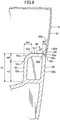
- Fig. 1 is a side elevation seen from the side of a toilet main unit, functional portion, and toilet lid in a flush toilet according to an embodiment of the invention
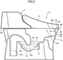
- Fig. 2 is a cross section showing the interior of a flush toilet according to an embodiment of the invention along a center cross section.
- the flush toilet 1 comprises a flush toilet 1, a toilet main unit 2, a toilet seat (not shown) disposed on the top surface of this toilet main unit 2, a toilet lid 4 disposed so as to cover the toilet seat, and a functional portion (water supply apparatus) 6 disposed at the rear of the toilet main unit 2.
- the toilet lid 4 and the functional portion 6 form an exterior member which primarily defines the exterior appearance of the upper portion of the toilet main unit 2.
- the toilet lid 4 it is also acceptable for the toilet lid 4 to be omitted, and the toilet seat (not shown) and functional portion 6 to form the exterior member primarily defining the external appearance of the upper portion of the toilet main unit 2.
- the toilet lid 4 or the functional portion 6 it is also acceptable for at least one of either the toilet lid 4 or the functional portion 6 to form the exterior member primarily defining the external appearance of the upper portion of the toilet main unit 2.
- the toilet main unit 2 is made of ceramic, and a bowl portion 8 for receiving waste, a discharge trap conduit 10 (discharge path) extending from the bottom portion of this bowl portion 8, a jet spout port 12 for jet spouting water, and a single rim spout port 14 (spouting portion) for rim spouting are formed on the toilet main unit 2.
- the jet spout port 12 is formed at the bottom portion of the bowl portion 8; it is disposed essentially horizontally toward the inlet of the discharge trap conduit 10, and ejects water toward the discharge trap conduit 10.
- a rim spout port 14 is formed at the left upper rear of the bowl portion 8; it ejects flush water along the edge of the bowl portion 8.
- a jet spout port 12 is formed on the toilet main unit 2
- the present invention is not limited to such a form and, for example, it is also acceptable for only a rim spout port to be formed of the jet spout portion and the rim spout port, with no jet spout port being formed.
- the discharge trap conduit 10 is made up of an inlet portion 10a, a trap ascending pipe 10b rising from this inlet portion 10a, and a trap descending pipe 10c dropping from this trap ascending pipe 10b.
- the flush toilet 1 is directly connected to a water utility supplying flush water; flush water is ejected from the rim spout port 14 by the water utility supply pressure.
- flush water stored in a water storage tank 28 built into the functional portion 6 is pressurized by a pressuring pump 30 and ejected from a jet spout port 12 at a high flow rate.
- the flush toilet 1 in the present embodiment is a hybrid flush toilet having a hybrid (water utility direct pressure + tank supply) water supply apparatus whereby with respect to rim spouting, the toilet is flushed by supplying water using water utility water pressure (water utility direct pressure supply), and with respect to jet spouting, flush water stored in the water storage tank 28 is pressurized by the pressurizing pump 30 and ejected from the jet spout port 12.
- a hybrid water utility direct pressure + tank supply
- flush toilet 1 functional portion 6 may also be applied for purposes other than a hybrid water supply apparatus.
- a water utility direct pressure type of flush toilet comprising only a water utility direct pressure type of water supply apparatus whereby water is supplied using water utility water pressure, or a flush toilet in which water is supplied by a flush valve system, or by using supplementary pump pressure, is also acceptable.
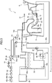
- Fig. 3 is an overview schematic showing a flush toilet according to an embodiment of the invention.
- a fixed flow rate valve (fixed flow rate device) 16 electromagnetic valve 18, rim spout vacuum breaker 20 for preventing reverse flow, and rim spout flapper valve 22 for preventing reverse flow are provided.
- a switching valve 26 for switching between supplying water to the tank and rim spouting, a water storage tank 28, a pressurizing pump 30, a vacuum breaker 32 for jet spouting, a flapper valve 34 for jet spouting, and a water drain 36 are built into the water supply path 24.
- the functional portion 6 can function as a water supply apparatus for supplying flush water to the toilet main unit 2.
- Flush water which has passed through the fixed flow rate valve 16 flows into the electromagnetic valve 18, and flush water which has passed through the electromagnetic valve 18 is supplied to the rim spout port 14 or the water storage tank 28 by the switching valve 26.
- This switching valve 26 is capable of supplying flush water to both the rim side supply path 14a on the rim side and the water storage tank 28 on the tank side at the same timing, and of changing the supply proportions water to the rim side and the tank side.
- the electromagnetic valve 18 is opened and closed by a control signal from the controller 38, allowing or stopping supplied flush water from flowing into the switching valve 26.
- the switching valve 26 is switched by a control signal from the controller 38, causing flush water flowing in through the electromagnetic valve 18 to be ejected from the rim spout port 14 or to flow into the water storage tank 28.
- the water storage tank 28 is constituted to store flush water to be spouted from the jet spout port 12. Note that in the present embodiment the water storage tank 28 has a capacity of approximately 2.5 liters.
- a top end float switch 28b and a bottom end float switch 28c are disposed inside the water storage tank 28 so that the water level inside the water storage tank 28 can be detected.
- the top end float switch 28b switches on, and the controller 38 senses this and closes the electromagnetic valve 18.
- the bottom end float switch 28c tuns on, and the controller 38 detects this and turns off the pressurizing pump 30.
- the pressurizing pump 30 pressurizes flush water stored in the water storage tank 28 and ejects it from the jet spout port 12.
- the pressurizing pump 30 is connected by a flush water conduit 30a extending from the lower portion of the water storage tank 28, and pressurizes flush water stored in the water storage tank 28.
- the pressurizing pump 30 pressurizes flush water in the water storage tank 28 and causes flush water to be spouted from the jet spout port 12 at a maximum flow rate of 120 liters/minute.
- a flapper valve 34 for jet spouting and a water drain 36 are disposed midway along the flush water conduit 30a.
- the outflow port on the pressurizing pump 30 is connected to the jet spout port 12 at the bottom portion of the bowl portion 8 through the flush water conduit 30b.
- the vacuum breaker 32 for jet spouting is connected to the branch conduit 32a which branches from the downstream side of the pressurizing pump 30 and the flush water conduit apex portion 42, preventing reverse flow by pooled water in the bowl portion 8 to the water storage tank 28 side and partitioning between those entities.
- the controller 38 by manipulation of a toilet flushing switch (not shown), sequentially operates the electromagnetic valve 18, switching valve 26, and pressurizing pump 30, sequentially starting the spouting of water from the rim spout port 14 and jet spout port 12 to flush the bowl portion 8.
- the controller 38 releases the electromagnetic valve 18, switching the switching valve 26 to the water storage tank 28 side and replenishing flush water to the water storage tank 28.
- the controller 38 closes the electromagnetic valve 18 and stops the supply of water.
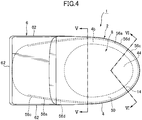
- Fig. 4 is a summary plan view showing a functional portion and a toilet lid attached to a toilet main unit in a flush toilet according to an embodiment of the invention.
- the bowl portion 8 comprises a waste receiving surface 44 formed in a bowl shape, and a rim portion 46, formed on the outside at the top of the entire perimeter of the bowl portion 8 and forming the upper edge of the toilet main unit 2. Also, a pooled water portion 48 is formed at the bottom of the bowl portion 8.In the pooled water portion 48, flush water is accumulated up to a predetermined amount after each flushing, and a pooled water surface W 0 is formed.
- the above-described discharge trap conduit 10 inlet portion 10a is opened at the bottom of this pooled water portion 48, and the bottom end of the discharge trap conduit 10 trap descending pipe 10c is connected to a discharge pipe (not shown) under the floor though a discharge socket (not shown).
- the sheet portion 50 extends forward from the inlet portion (not shown) connected to the rim side supply path 14a which extends from the functional portion 6, and communicates with the rim spout port 14, which opens forward on the left side of the front region of the bowl portion 8 on the front side relative to the left-right extending center line, which equally divides the bowl portion 8 in the front to back direction.
- the rim spout port 14 spouts flush water forward from the front region of the bowl portion 8, forming a flow toward the front end of the bowl portion 8, and also forming a flow which reverses from the front end 8a of the bowl portion 8 toward the rear side.
- Flush water spouted from the rim spout port 14 is spouted from the rim spout port 14 in the front to back direction of the toilet onto the surface between the rim portion 46 and the rim portion 46 vertical wall 52b forming a circulating current; a falling current is formed in which this circulating current flows downward as it circulates from the rim portion 46 vertical wall 52b over the waste receiving surface 44 in the direction of the pooled water portion 48.
- Fig. 5 is a cross section seen along line V-V in Fig. 4 ;
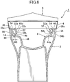
- Fig. 6 is a cross section seen along line VI-VI in Fig. 4 ;
- Fig. 7 is a summary expanded cross section seen from the side of a toilet main unit showing the positional relationship between a toilet lid bottom end portion and the rim outer wall upper sloped surface of the toilet main unit rim portion, with the toilet lid closed in a flush toilet according to an embodiment of the invention;
- Fig. 8 is a summary expanded cross section showing the positional relationship between a toilet lid bottom end portion and the rim outer wall upper sloped surface of the toilet main unit rim portion relative to the rim portion vicinity in Fig. 5 .
- the rim portion 46 comprises: a rim inner wall portion 52 forming the inner perimeter surface of the rim portion 46 and formed in a standing wall shape rising from the top end 44a of the waste receiving surface 44 up to the apex portion of the toilet main unit 2, a rim top surface portion 54 forming the top surface of this rim portion 46, and a rim outer wall portion 56 forming the outer perimeter surface of the rim portion 46 and formed in a standing wall shape rising up the outside surface of the toilet main unit 2 up to the rim top surface portion 54.
- the rim inner wall portion 52 comprises a rim inner wall upper sloped surface 52a wherein the inside of the upper region of the rim inner wall portion 52 (the waste receiving surface 44 side) slopes downward, and a vertical wall 52b forming a wall surface in the vertical direction up to the rim inner wall upper sloped surface 52a.
- the rim inner wall portion 52 is formed over the entire perimeter on the inside of the rim portion 46.
- the vertical wall 52b is formed so that in most of the region it rises essentially vertically, but of the rim inner wall portion 52, in a part of the region from the rim spout port 14 of the bowl portion 8 forward, the top portion of the vertical wall 52b and the rim inner wall upper sloped surface 52a are formed in an overhanging shape toward the inside of the bowl portion 8.
- the vertical wall 52b forms a wall surface which rises in the vertical direction from the waste receiving surface 44 top end 44a to the rim inner wall upper sloped surface 52a bottom end 52c.
- the vertical wall 52b may also be a vertical wall rising vertically from the top end of the waste receiving surface 44.
- the height of the rim inner wall portion 52 is formed in a relatively limited range of heights, from the top end 44a of the waste receiving surface 44 positioned relative to the height of the drain pipe, to the apex portion of the toilet main unit 2 positioned relative to the height of the toilet main unit 2. Therefore in the rim inner wall portion 52, it is the rim inner wall upper sloped surface 52a which is of itself formed on the top portion thereof, such that in the remaining part the height of the vertical wall 52b forming the vertical wall up to the rim inner wall upper sloped surface 52a is formed to be relatively low.
- the rim inner wall upper sloped surface 52a of the rim inner wall portion 52 is formed over a region at a height H2 in a range of 10% to 60% of the height H1 of a predetermined region from the top end to the bottom end of the rim inner wall portion 52.
- the rim inner wall portion 52 vertical wall 52b viewed in vertical cross section, is formed over a region at a height H3 in a range of 40% to 90% of the height H1 of a predetermined region from the top end to the bottom end of the rim inner wall portion 52.
- the rim inner wall upper sloped surface 52a forms a sloped portion smoothly connecting the corner portion between the horizontally oriented rim top surface portion 54 and the vertically oriented vertical wall 52b.
- the rim inner wall upper sloped surface 52a forms an arc shape projecting toward the center top of the bowl portion 8.In other words, it forms an arc shape which connects the rim top surface portion 54 and the inside perimeter wall surface 52b.
- the rim inner wall upper sloped surface 52a is formed so that its outside top end 52d is positioned at the height of the rim top surface portion 54, and the inside of the rim inner wall upper sloped surface 52a slopes downward; and the top of the rim inner wall upper sloped surface 52a is formed to widen toward the outside more than the bottom end 52c.
- rim inner wall upper sloped surface 52a may also be formed into a curved surface shape so as impart rounding to the entirety while including a relatively flat surface in a part of the surface between the rim top surface portion 54 and the vertical wall 52b.
- the sloped portion smoothly connecting the horizontally oriented rim top surface portion 54 and the vertically oriented vertical wall 52b of the rim inner wall upper sloped surface 52a may also be formed by a beveled surface. I.e., the surface between the rim top surface portion 54 and the vertical wall 52b may be formed by a flat surface of a predetermined angle.
- the beveled surface may preferably form a flat surface within an angular range of 20° to 70° relative to the plumb line passing through the rim inner wall upper sloped surface 52a bottom end 52c, and more preferably may form a flat surface within an angular range of 35° to 55°.
- the beveled surface may also form a flat surface with a 45° angle relative to the plumb line passing through the bottom end 52c thereof.
- the rim inner wall upper sloped surface 52a is formed in an arc shape so that the slope of the tangent on the surface thereof changes continuously according to position. Therefore when a user places his hand to fit the rim inner wall upper sloped surface 52a, the occurrence of a space between his hand and the rim inner wall upper sloped surface 52a can be constrained, and the hand can be naturally placed to follow the entire curved surface. Note that the rim inner wall upper sloped surface 52a may also be formed by a curved surface of another shape to match the curve in the human hand.
- fitting of a user's hand to the rim inner wall upper sloped surface 52a includes cases of fitting the hand to the rim inner wall upper sloped surface 52a mediated by a cleaning cloth or paper such as toilet paper for cleaning the toilet, etc.
- fitting of a user's hand to the rim inner wall upper sloped surface 52a includes cases in which the user fits his hand to the rim inner wall upper sloped surface 52a mediated by a cleaning cloth or the like with gloves or the like on the user's hand.
- a waste receiving surface 44 forming a curved surface descending as it curves at the center is disposed at the center in the left-right direction of the toilet main unit 2 (the cross sectional direction when the toilet main unit 2 is viewed from the front); and a rim inner wall upper sloped surface 52a forming a curved surface, the inside of which similarly drops downward, is disposed on the outside of the waste receiving surface 44. Therefore when seen from the top plan view, a rim inner wall upper sloped surface 52a with a gradually inward descending curved surface connects to the outside perimeter of the waste receiving surface 44, and can thereby convey to a user the impression of forming a continuous outwardly spreading curved surface.
- a user can receive the impression that the waste receiving surface 44 is still further widened outward by the region of the rim inner wall upper sloped surface 52a.
- the worry that urine will miss the waste receiving surface 44 is constrained by conveying to the user the impression that the waste receiving surface 44 is wide, thereby enabling the user to urinate with ease.
- the bottom end 52c of the rim inner wall upper sloped surface 52a is placed above the rim spout port 14 apex portion 14b. More particularly, the bottom end 52c of the rim inner wall upper sloped surface 52a is placed above the rim spout port 14 apex portion 14b. Put another way, the vertical wall 52b is formed up to a height above the apex portion 14b of the rim spout port 14. Therefore the rim spout port 14 spouts flush water so that it contacts the vertical wall 52b on the proximate downstream side.
- a rim inner wall upper sloped surface 52a of the type described above is formed in a relatively gentle arc shape, with a relatively wide width in the left-right direction.
- the width W1 in the horizontal direction (e.g., the direction from the inside toward the outside of the toilet main unit) between the top end 52d and the bottom end 52c of the rim inner wall upper sloped surface 52a is formed to be larger than the left-right width W3 of the rim spout port 14 opening.
- the bottom end 52c of the rim inner wall upper sloped surface 52a is placed above the rim spout port 14, therefore the horizontal width W1 of the rim inner wall upper sloped surface 52a can be formed to be relatively large, and the vertical height H1 of the rim inner wall upper sloped surface 52a can also be formed to be relatively large. Hence the rim inner wall upper sloped surface 52a can be formed to slope downward on the inside along a gradual arc shape with a large diameter.
- the rim top surface portion 54 forms a lateral surface extending in the horizontal direction, and also forms the apex surface of the toilet main unit 2.
- a user to clean the rim portion 46 of the toilet main unit 2 requires cleaning the rim inner wall upper sloped surface 52a and vertical wall 52b with the user's palm or the like disposed on the rim top surface portion 54 to follow it horizontally, and with fingers bent.
- the rim top surface portion 54 is not limited to a horizontal surface, and may also be formed as a downward sloping surface or an upward sloping surface toward the bowl portion 8.
- the rim top surface portion 54 may be formed by a curved surface.
- the rim top surface portion 54 may also be formed as part of a curving surface in which the outer end of the rim inner wall upper sloped surface 52a is extended to the outside, or may be formed as part of a curving surface in which the inner end of the rim outer wall upper sloped surface 56a is extended to the inside.
- the rim top surface portion 54 is formed as a part of the rim inner wall upper sloped surface 52a, the outer end of the rim inner wall upper sloped surface 52a and the inner end of the rim outer wall upper sloped surface 56a can be relatively smoothly connected, and the rim portion 46 top surface formed.
- the rim outer wall portion 56 comprises a rim outer wall upper sloped surface 56a which connects a horizontally oriented rim top surface portion 54 and a vertically oriented rim outer wall and forms the outside edge (the outside of toilet main unit 2) on the top portion of the rim portion 46, and a rim outer wall 56b which forms a wall in the vertical direction up to the rim outer wall upper sloped surface 56a.
- the top end 56d thereof is positioned at the height of the rim top surface portion 54 between the rim top surface portion 54 and the rim outer wall 56b, and the outer side thereof forms a sloped surface sloping downward.
- the rim outer wall upper sloped surface 56a is formed as a 45° sloped surface (beveled surface) having a 45° slope angle relative to plumb (or 45° relative to the planar direction of the rim top surface portion 54).
- the rim outer wall upper sloped surface 56a may be formed as a sloped surface (beveled surface) with another slope angle relative to the plumb direction; e.g., it is preferably formed as a sloped surface with a slope angle (beveled surface) in a range of 20° to 70°.
- rim outer wall upper sloped surface 56a may also form a curved surface with a gentle curve between the rim top surface portion 54 and the rim outer wall 56b.
- the rim outer wall upper sloped surface 56a may also be formed by an arc with a radius r of 5 mm to 8 mm.
- the rim inner wall upper sloped surface 52a when seen in vertical cross section is formed by an arc having a radius R of 10 mm to 30 mm and more preferably 16 mm to 25 mm.
- the ratio of the radius r of the arc forming the rim outer wall upper sloped surface 56a to the radius R of the arc forming the rim inner wall upper sloped surface 52a is formed in a range of 1:2 to 1:5.
- the rim inner wall upper sloped surface 52a horizontal width W1 (e.g., the direction from inside toward the of the toilet main unit) is formed to be wider than the horizontal width W2 (e.g., the direction from inside toward the of the toilet main unit) between the top end 56d and the bottom end 56c of the rim outer wall upper sloped surface 56a.
- the rim inner wall upper sloped surface 52a and rim outer wall upper sloped surface 56a are formed by a sloped surface, therefore when a user places his hand on the rim inner wall upper sloped surface 52a and the rim outer wall upper sloped surface 56a, the hand can be disposed naturally along the rim inner wall upper sloped surface 52a and the rim outer wall upper sloped surface 56a, and an easily gripped shape is formed, without producing a relatively large space between the hand and the rim portion 46.
- the vertical wall 52b and rim inner wall upper sloped surface 52a are formed in an overhanging shape toward the inside, so the rim portion 46 is made easier to grip such that an installer, manufacturer, or the like can lift it up with hands placed on the inside of the rim portion 46 overhang shape. Therefore when an installer or manufacturer carries the toilet, placement of hands on the rim portion 46 formed in an overhanging shape enables the load being lifted upward to act more easily on the rim portion 46, with fingertips locked into the underside of the rim inner wall upper sloped surface 52a, facilitating carrying of the toilet.
- the toilet lid bottom end portion 60 of the side wall 58 on the toilet lid 4 is disposed at the height of the rim outer wall upper sloped surface 56a.
- the side walls 58 on toilet lid 4 include vertical walls on the left and right sides and on the front side when viewed from the front side of the toilet main unit 2.
- the external part of the exterior member is formed, for example, by the toilet lid 4 side walls 58, by the functional portion 6 side walls and rear walls etc. described below and, in another variant example described below, by the toilet seat side portion, etc.
- the toilet lid bottom end portion 60 of the side walls 58 in the toilet lid 4 comprises: a toilet cover bottom end surface 60a forming the bottom-most surface of that toilet lid bottom end portion 60, a toilet lid inner surface 60b which forms the inner surface of the toilet lid bottom end portion 60, and a toilet lid outer surface 60c.
- the toilet lid bottom end portion 60 is positioned between the top end 56d and the bottom end 56c of the rim outer wall upper sloped surface 56a. More particularly, the toilet lid bottom end portion 60 of the toilet lid 4 is disposed at a height below the height of the rim portion 46 rim top surface portion 54, and is disposed at a height above the height of the bottom end 56c of the rim outer wall upper sloped surface 56a.
- the toilet lid inner surface 60b of the toilet lid bottom end portion 60 is disposed at a position further inside the toilet than the position of the bottom end 56c of the rim outer wall upper sloped surface 56a.
- the toilet lid outer surface 60c of the toilet lid bottom end portion 60 is disposed in the same position as the position of the rim outer wall upper sloped surface 56a bottom end 56c, or at a position further outside the toilet than the position of the rim outer wall upper sloped surface 56a bottom end 56c.
- the toilet lid bottom end portion 60 toilet lid outer surface 60c and the rim outer wall 56b are disposed in an essentially flush relationship, or the toilet lid bottom end portion 60 toilet lid outer surface 60c is disposed further outside the toilet than the rim outer wall 56b.
- the toilet lid bottom end portion 60 of toilet lid 4 is positioned between the top end 56d and the bottom end 56c of the rim outer wall upper sloped surface 56a, therefore when viewed from the toilet side direction, the toilet lid bottom end portion 60 of the toilet lid 4 side walls 58 appears to overlap with the rim outer wall upper sloped surface 56a.
- the toilet main unit 2 is made of ceramic, unevenness 54a caused by manufacturing tolerances such as shrinkage tolerances during vitrification when the toilet main unit 2 is manufactured may occur on the rim top surface portion 54. If unevenness 54a does occur on the rim top surface portion 54, the toilet lid bottom end portion 60 can extend further down than the unevenness 54a so as to hide the unevenness 54a. Therefore when seen from the side, the boundary between the toilet lid bottom end portion 60 and the rim outer wall upper sloped surface 56a can be shown as the boundary between the toilet lid 4 and the rim outer wall portion 56 as a single line aligned in a straight line manner, without the unevenness 54a on the rim top surface portion 54 being visible to the user, so that an aesthetic impression is conveyed to the user.
- a gap S is formed between the toilet cover bottom end surface 60a and the rim outer wall upper sloped surface 56a.
- a gap S by which the distance between the toilet cover bottom end surface 60a and the rim outer wall upper sloped surface 56a is minimized is positioned below the top end 56d and above the bottom end 56c, and is also below the rim top surface portion 54.
- the toilet cover bottom end surface 60a and the rim outer wall upper sloped surface 56a are arranged not to make direct contact, but when viewed from the lateral direction (the side surface direction), at least a portion of the toilet lid 4 side wall appears to be connected on the rim outer wall upper sloped surface 56a; furthermore the boundary between the toilet cover bottom end surface 60a and the rim outer wall upper sloped surface 56a is perceived as a single aligned straight line with a straight line shape extending in the front to back direction of the toilet cover bottom end surface 60a, so an aesthetic impression can be imparted to the user.
- the toilet cover bottom end surface 60a shifts up/down or left/right from the originally intended position due to tolerances in attachment (installation) of the toilet lid 4 to the rim portion 46 or toilet manufacturing tolerances, etc.
- the toilet cover bottom end surface 60a is positioned between the top end 56d and the bottom end 56c of the rim outer wall upper sloped surface 56a, then when viewed from the toilet lateral direction the toilet cover bottom end surface 60a will appear to be overlapping and connected on the rim outer wall upper sloped surface 56a; moreover, the boundary between the toilet cover bottom end surface 60a and the rim outer wall upper sloped surface 56a can be made to appear as a single aligned straight line.
- the functional portion 6 is disposed on the rim top surface portion 54 at the rear of the toilet main unit 2, and the functional portion 6 side wall and rear wall functional portion bottom end portion 62 is disposed on the the rim top surface portion 54, but as a variant example it is also acceptable for at least a portion of this functional portion 6 side wall and rear wall functional portion bottom end portion to be extended to a height matching the height of the rim top surface portion 54 or to a height below the rim top surface portion 54, so as to be positioned between the top end 56d and the bottom end 56c of the rim outer wall upper sloped surface 56a.
- the functional portion bottom end portion When the functional portion bottom end portion is thus positioned between the top end 56d and bottom end 56c of the rim outer wall upper sloped surface 56a, the functional portion side wall and the rear wall functional portion bottom end portion will appear to overlap the rim outer wall upper sloped surface 56a when seen from the toilet lateral direction. If unevenness 54a does occur on the rim top surface portion 54, the functional portion bottom end portion can extend further down than the unevenness 54a so as to hide the unevenness 54a.
- the boundary between the functional portion bottom end portion and the rim outer wall upper sloped surface 56a can be shown as the boundary between the functional portion 6 and the rim outer wall portion 56 as a single line aligned in a straight line manner, without the unevenness 54a on the rim top surface portion 54 being visible to the user, so that an aesthetic impression is conveyed to the user.
- the flush toilet 1 comprises a toilet seat (not shown) disposed on the top surface of the toilet main unit 2, and a toilet lid 4 disposed to cover the toilet seat, but as another variant example the toilet lid 4 may be omitted and a toilet seat disposed on the rim top surface portion 54 on the top surface of the toilet main unit 2 to be applied to a flush toilet functioning as an exterior member determining the outside appearance of the toilet.
- At least a portion of the toilet seat bottom end portion on the side part of the toilet seat may be extended to a height matching the height of the rim top surface portion 54, or to a height below the rim top surface portion 54, so as to be positioned in the height direction between the top end 56d and the bottom end 56c of the rim outer wall upper sloped surface 56a.
- the toilet seat bottom end portion of the toilet seat side portion will appear to overlap the rim outer wall upper sloped surface 56a when seen from the toilet lateral direction. If unevenness 54a does occur on the rim top surface portion 54, the toilet seat bottom end portion can extend further down than the unevenness 54a so as to hide the unevenness 54a.
- the boundary between the toilet seat bottom end portion and the rim outer wall upper sloped surface 56a can be shown as the boundary between the functional portion 6 and the rim outer wall portion 56 as a single line aligned in a straight line manner, without the unevenness 54a on the rim top surface portion 54 being visible to the user, so that an aesthetic impression is conveyed to the user.
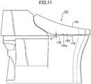
- Fig. 11 is a side elevation seen from the side of a toilet main unit, functional portion, and toilet lid in a conventional flush toilet
- Fig. 12 is a summary expanded cross section showing the positional relationship between a toilet lid bottom end portion and the rim outer wall upper sloped surface of the toilet main unit rim portion relative to the rim portion vicinity of a conventional flush toilet.
- a toilet lid toilet lid bottom edge portion 160 is disposed above the rim top surface portion 154 when the toilet lid 104 is closed.
- the toilet lid bottom edge portion 160 and the rim outer wall portion (rim outside edge portion) 156 not make contact, therefore the toilet lid bottom edge portion 160 is disposed outside and above the rim outer wall portion (rim outside edge portion) 156. Therefore a gap C is formed between the toilet lid bottom edge portion 160 and the rim top surface portion 154, and between the toilet lid bottom edge portion 160 and the rim outer wall portion 156.
- a gap C appears to be formed between the toilet lid bottom edge portion 160 and the rim outer wall portion 156, so that in the boundary between the toilet lid 104 and the rim outer wall portion 156, the toilet lid bottom end portion 160 bottom end, the gap C, and the rim outer wall portion 156 top end each appear separately, and the boundary appears as multiple lines, not as a single line. Also, because of the presence of the gap C between the toilet lid bottom edge portion 160 and the rim outer wall portion 156, the toilet interior becomes visible from the gap C, so that an aesthetic impression can no longer be conveyed to the user.
- an unevenness 154a is visible on the rim top surface portion 154 in the gap C at the boundary of the boundary between the toilet lid bottom edge portion 160 and the rim top surface portion 154, and the boundary between the toilet lid bottom edge portion 160 and the rim top surface portion 154 appears as an uneven line, so the user cannot be shown a single aligned straight line, and an aesthetic impression cannot be imparted to users.
- Fig. 9 is a diagram showing the state in which a user's hand is placed to follow along the rim inner wall upper sloped surface of the rim portion in a flush toilet according to an embodiment of the invention
- Fig. 10 is a diagram showing the state in which a user's hand is placed on the rim inner wall upper edge portion of a conventional flush toilet.
- the user's hand and fingers is denoted in this explanation by an H.
- the user when a user seeks to clean the rim portion 46 as shown in Fig. 9 , the user cleans with his hand and fingers H positioned so that the palm Ha and/or palm side of the hand Hb contact the rim upper surface portion 54, thereby cleaning the vertical wall 52b on the fingertip Hd side.
- the rim top surface portion 54 forms a generally horizontal plane
- the vertical wall 52b forms a generally plumb wall surface, therefore a user bends his finger joints to clean the vertical wall 52b side.
- the rim inner wall upper sloped surface 52a forms a relatively large radius arc, so the bent part of the fingers (e.g., Hc, Hd) may be bent gradually, and the bent part of the fingers (e.g., Hc) may be positioned to fit the arc in the rim inner wall upper sloped surface 52a.
- a user for example, can efficiently clean a rim top surface portion 54, a rim inner wall upper sloped surface 52a, and a vertical wall 52b simultaneously with the palm side part Hb on the finger joint side of the user's hand H in contact with the rim top surface portion 54, and the second finger joint part Hc in contact with the rim inner wall upper sloped surface 52a, and with the finger tip part Hd in contact with the vertical wall 52b.
- a user can place his hand and fingers H in contact with the rim top surface portion 54, the rim inner wall upper sloped surface 52a, and the vertical wall 52b without bending the hand and fingers forcedly, a user can easily impart the force needed for cleaning to the hand and fingers H. Therefore the cleanability of the rim top surface portion 54, the rim inner wall upper sloped surface 52a, and the vertical wall 52b is also improved.
- a conventional rim inner wall upper edge portion 152a is formed in the rim portion 146.
- the rim inner wall upper edge portion 152a forms a connecting part (edge portion) consisting of a relatively small radius arc (an arc with essentially the same radius as the rim outer wall upper sloped surface 156a), so that bent finger parts such as the second finger joint part Hc cannot be positioned to fit the arc of the rim inner wall upper edge portion 152a.
- the second finger joint part Hc on the user's hand H becomes separated from the rim inner wall upper edge portion 152a, and the fingertip part Hd is separated from the vertical wall 152b.
- the limited movable range of the human finger joints means that even if the hand is excessively bent so that the finger joint side portion of fingers Hb of the user's hand H is in contact with the rim top surface portion 154, and the second finger joint part Hc is in contact with a part of the top portion of the rim inner wall upper edge portion 152a, not only will contact not be possible between the second finger joint part Hc and the conventional rim inner wall upper edge portion 152a lower portion, but the fingertip part Hd and the vertical wall 152b also cannot be placed in a contacting state. Therefore problems arise with cleaning the rim inner wall upper edge portion 152a and the vertical wall 152b, and even more cleaning work results.
- the limited movable range of the human finger joints means that even if the hand is excessively bent so that the finger joint side portion of fingers Hb of the user's hand H is in contact with the rim top surface portion 154, and the fingertip part Hd is in contact with the vertical wall 152b, it is not possible to simultaneously place the second finger joint part Hc and the rim inner wall upper edge portion 152a in a contacting state. Therefore problems arise with cleaning the rim inner wall upper edge portion 152a, and even more cleaning work results.
- the rim top surface portion 154 and a part of another curved surface cannot be simultaneously placed in a contacting state unless the user's hand H is excessively bent, so it is difficult for the user to apply the force to hand H required for cleaning. Therefore problems arise with the cleanability of the rim top surface portion 154, the conventional rim inner wall upper edge portion 152a, and the vertical wall 152b.
- the rim inner wall portion 52 comprises a rim inner wall upper sloped surface 52a in which the inside of the upper region of the rim inner wall portion 52 slopes downward.
- a user wipes clean a rim portion 46, he can efficiently clean the rim portion 46 rim top surface portion 54, rim inner wall upper sloped surface 52a, and vertical wall 52b with his own hand placed from the rim portion 46 top surface to the vertical wall 52b so as to follow the rounding of the rim inner wall upper sloped surface 52a.
- cleaning can be performed while applying a relatively uniform force from the rim portion 46 top surface portion 54 to the rim inner wall upper sloped surface 52a and vertical wall 52b, the user can easily impart a relatively strong force to the entirety of the rim portion to be wiped clean, so that cleaning performance can be improved.
- the rim inner wall portion 52 comprises a rim inner wall upper sloped surface 52a, wherein the inside of the upper region of a rim inner wall portion 52 slopes downward. Therefore the rim inner wall upper sloped surface 52a formed on the upper and outer side of the waste receiving surface 44 can give the user the impression that the waste receiving surface 44 widens further outward, and the bowl portion 8 can be made to appear relatively larger than in the past, thereby imparting a feeling of ease so that the user can discharge urine more easily into the bowl portion 8 during use.
- the rim portion 46 comprises a rim outer wall upper sloped surface 56a being positioned in an outside of an upper region of the rim outer wall 56 and being sloped downward toward an outer of the bowl portion, therefore at least a portion of the exterior part of the toilet lid 4 positioned on the rim portion 46 can be easily assembled and positioned at the height of the rim outer wall upper sloped surface 56a; furthermore, viewed from the toilet lateral direction, the boundary between the exterior part of at least a part of the toilet lid 4 and the rim outer wall upper sloped surface 56a appears as a single straight, aligned line, so that an aesthetic impression can be imparted to the user.
- a horizontal distance W1 between an top end of the rim inner wall upper sloped surface and a bottom end of the rim inner wall upper sloped surface 52a is formed to be longer than a horizontal distance W2 between an top end of the rim outer wall upper sloped surface and a bottom end of the rim outer wall upper sloped surface 56a, therefore when a user wipes clean the rim portion 46, he can clean the rim portion 46 rim top surface portion 54, the rim inner wall upper sloped surface 52a, and the rim inner wall portion 52 efficiently with his own hand placed from the top portion of the rim portion 46 up to the inner wall of the rim portion 46 so as to follow the sloping surface of the rim inner wall upper sloped surface 52a.
- flush water spouted from the rim spout port 14 is circulated along a region below the bottom end 52c of the rim inner wall upper sloped surface 52a, therefore flush water can be constrained from exceeding the rim inner wall upper sloped surface 52a and splashing outside the toilet. Because flush water is circulated in this manner along a region below the bottom end 52c of the rim inner wall upper sloped surface 52a, the width and size, etc. of the rim inner wall upper sloped surface 52a can be formed to be relatively large.
- the present invention is not limited to such embodiments; for example, a similar effect can be obtained if the position of the bottom end 52c of the rim inner wall upper sloped surface 52a at the maximum height reached by flush water in the rim spout port 14 is high.
- an arrangement is acceptable whereby if the height of flush water spouted from the rim spout port 14 reaches only the center of the rim spout port 14, the bottom end 52c of the rim inner wall upper sloped surface 52a will be at a higher position than the center of the rim spout port 14.
- the radius of the arc forming the rim inner wall upper sloped surface 52a is formed to be a radius easily gripped by the curve in a user's hands. It is therefore easy for the user's own hand to follow the arc shape forming the rim inner wall upper sloped surface 52a when a user is wiping clean the rim portion 46.
- installers, manufacturers, and the like can, when transporting the toilet, carry the toilet in a favorable manner by placing hands on the rim portion 46 formed with overhangs, with hands gripping.
- the rim spout port 14 can form a circulating current flowing from the bowl portion 8 front end 8a toward the rear, and the bowl portion can be sufficiently flushed while conserving water.
- the rim portion 46 in the region from the bowl portion 8 rim spout port 14 to the front side thereof, where flush water spouted from the rim spout port 14 can easily pass over the rim portion 46 and splash outside the toilet, the rim portion 46 has an upper portion that overhangs inwardly being disposed on the front side of an outlet of the rim spout port 14 , therefore splashing of flush water outside the toilet can be constrained.
- the surge of flush water supplied by a flush water supply apparatus (functional portion 6) using water utility supply pressure from a flush water source during spouting is relatively constrained. It is therefore more difficult for flush water spouted from the rim spout port 14 to pass from the bowl portion 8 over the rim portion 46 and splash, and the width of the rim inner wall upper sloped surface 52a can be made wide.
- the rim portion 46 comprises a rim outer wall upper sloped surface 56a wherein the outside of the upper region of the rim outer wall 56b slopes downward, and the bottom end of at least a portion of the exterior part of the toilet lid 4 is disposed at a height below the height of the rim portion 46 rim to surface portion 54, so that at least a portion of the exterior part of the toilet lid 4 can be disposed at the height of the rim outer wall upper sloped surface 56a.
Description
- The present invention pertains to a flush toilet, and more particularly to a flush toilet for discharging waste by flushing a toilet main unit using flush water supplied from a flush water source.
- As disclosed in Patent Document 1 (Patent No.
04941796 - Document
US 3 593 349 A discloses a toilet having a seat covering the upper part of the rim. This rim comprises an upper slopped part which is covered by the seat. - Documents
US 2012/198610 A1 andUS/251471 A1 relate to toilet without any exterior member. - Document
US 2003/088910 A1 relates to a toilet comprising a housing which does not comprise any part covering partially or not the rim of the toilet. -
JP 2008 127964 A - In such conventional flush toilets, because of the requirement that the toilet lid
bottom edge portion 160 and rimouter wall portion 156 generally not contact, as shown inFig. 11 , the toilet lidbottom edge portion 160 is disposed outside and above the rimouter wall portion 156. Therefore a gap C is formed between the toilet lidbottom edge portion 160 and the rimtop surface portion 154. - In such cases, the problem arose that when a user viewed the toilet from the side, the gap C formed between the toilet lid
bottom edge portion 160 and the rimouter wall portion 156 was visible, and the boundary did not appear as a single line. - A further problem was that because an
unevenness 154a is visible on the rimtop surface portion 154 in the gap C, and the boundary between the toilet lidbottom edge portion 160 and the rimtop surface portion 154 appears as an uneven line, the user cannot be shown a single aligned straight line, and an aesthetic impression cannot be imparted to users. - The present invention therefore has the object of providing a flush toilet with which, when installing an exterior member on a rim portion, at least a part of the exterior part of the exterior member can be easily installed and registered at the height of the rim outer wall upper sloped surface, and seen from the toilet lateral direction, the border between at least a part of the exterior part of the exterior member and the rim outer wall upper sloped surface appears as a single aligned straight line, imparting an aesthetic impression to the user.
- To achieve the above-described object, the invention is a flush toilet comprising: a bowl portion including a bowl-shaped waste receiving surface and a rim portion formed on a top edge of the waste receiving surface; a water discharge path for discharging waste, the water discharge path having an inlet that is connected at a bottom of this bowl portion; a water spouting portion for spouting flush water to the bowl portion to generate a circulating current; a water conduit for supplying flush water to the water spouting portion; and an exterior member including an exterior part disposed over the rim portion; wherein the rim portion comprises a rim outer wall portion forming an outer perimeter of the rim portion, and a rim inner wall portion forming the inner perimeter of the rim portion; the rim outer wall portion comprises a rim outer wall upper sloped surface being positioned in an outside of an upper region of the rim outer wall portion and being sloped downward toward an outer of the bowl portion; and at least a part of the exterior part is disposed at the height of the rim outer wall upper sloped surface.
- In the invention thus constituted, the rim portion comprises a rim outer wall upper sloped surface being positioned in an outside of an upper region of the rim outer wall portion and being sloped downward toward an outer of the bowl portion, therefore at least a part of the exterior part of the exterior member installed on the rim portion can be easily installed and registered at the height of the rim outer wall upper sloped surface; moreover, seen from the side of the toilet the boundary between at least a part of the exterior part of the exterior member and the rim outer wall upper sloped surface appears to be a single straight aligned line, and and aesthetic impression can be imparted to the user.
- In the present invention the rim inner wall portion preferably further comprises a rim inner wall upper sloped surface being positioned inan inside of an upper region of the rim inner wall portion and being sloped downward toward an inner of the bowl portion, and in at least a part of an entire perimeter of the rim portion, a horizontal distance between an top end of the rim inner wall upper sloped surface and a bottom end of the rim inner wall upper sloped surface is formed to be longer than a horizontal distance between an top end of the rim outer wall upper sloped surface and a bottom end of the rim outer wall upper sloped surface .
- In the invention thus constituted, a horizontal distance between an top end of the rim inner wall upper sloped surface and a bottom end of the rim inner wall upper sloped surface is formed to be longer than a horizontal distance between an top end of the rim outer wall upper sloped surface and a bottom end of the rim outer wall upper sloped surface in at least a part of an entire perimeter of the rim portion, therefore when a user wipes clean the rim portion, the rim portion upper part, the rim inner wall upper sloped surface, and the rim inner wall portion can be efficiently cleaned with the user's own hand placed so as to follow from the rim portion upper portion up to the rim portion inner wall so as to follow along the sloping surface of the rim inner wall upper sloped surface from the upper part of the rim portion.
- In addition, because cleaning can be performed while applying a relatively uniform force from the rim portion top surface to the rim inner wall upper sloped surface and rim inner wall portion, the user can easily impart a relatively strong force to the entirety of the rim portion to be wiped clean, so that cleaning performance can be improved.
- In the present invention a bottom end of the rim inner wall upper sloped surface is preferably disposed above a top end of the spouting portion.
- In the invention thus constituted, flush water spouted from the spouting portion is circulated along a region below a bottom end of the rim inner wall upper sloped surface, therefore flush water can be constrained from passing over the rim inner wall upper sloped surface and splashing outside the toilet. Because flush water is circulated in this manner along a region below the bottom end of the rim inner wall upper sloped surface, the width and size, etc. of the rim inner wall upper sloped surface can be formed to be relatively large.
- In the present invention, preferably, the rim inner wall upper sloped surface is formed in an arc shape; the rim inner wall upper sloped surface is formed in an arc shape; and a ratio between the radius of the arc forming the rim outer wall upper sloped surface and the arc forming the rim inner wall upper sloped surface is formed in a ranges from 1:2 to 1:5 inclusive.
- In the invention thus constituted, the radius of the arc forming the rim inner wall upper sloped surface is formed to be easily grasped by the bend in a user's hand. It is therefore easy for the user's own hand to follow the arc shape forming the rim inner wall upper sloped surface when wiping clean the rim portion.
- In the present invention, preferably, the rim portion is formed so that at least a portion of the rim inner wall portion is overhangs inwardly.
- In the invention thus constituted, when transporting the toilet, installers, manufacturers, and the like can carry the toilet in a favorable manner by placing hands on the rim portion formed with overhangs, with hands gripping.
- In the present invention, preferably, an outlet of the spouting portion is formed in a front region of the bowl portion such that the flush water swirls from the front end of the bowl portion toward a rear of the bowl portion to generate the circulating current.
- In the invention thus constituted, the spouting portion can form a circulating current flowing rearward from the front end of the bowl portion, sufficiently flushing the bowl portion while conserving water.
- In the present invention, preferably, the spouting portion is formed to spout to the front of the bowl portion, the rim portion has an upper portion that overhangs inwardly being disposed on the front side of an outlet of the spouting portion.
- In the invention thus constituted, from the bowl portion spouting portion to the front side region where flush water spouted from the spouting portion can easily pass over the rim portion and splash outside the toilet, the rim portion has an upper portion that overhangs inwardly being disposed on the front side of an outlet of the spouting portion, therefore splashing of flush water outside the toilet can be constrained.
- In the present invention, preferably, the flush water supplied to the water conduit by a flush water supply apparatus using water utility supply pressure from a flush water source.
- In the invention thus constituted, the strength of the surge of flush water supplied by a flush water supply apparatus using water utility supply pressure from a flush water source during spouting can be relatively constrained. Therefore it is more difficult for flush water spouted from the spouting portion to pass from the bowl over the rim portion and splash, and the width of the rim inner wall upper sloped surface can be made large.
- In the present invention, preferably, a bottom end of at least a portion of the external part is disposed at a height lower than the height of the top surface of the rim portion.
- In the invention thus constituted, the rim portion comprises a rim outer wall upper sloped surface in which the outside of the upper region of the rim outer wall slopes downward, and a bottom end of at least a portion of the external part is disposed at a height lower than the height of the top surface of the rim portion, therefore at least a portion of the external part of the exterior member can be disposed at the height of the rim outer wall upper sloped surface.
- Using the flush toilet of the present invention, when installing an exterior member on a rim portion at least a part of the exterior part of the exterior member can be easily installed and registered at the height of the rim outer wall upper sloped surface, and seen from the toilet lateral direction, the border between at least a part of the exterior part of the exterior member and the rim outer wall upper sloped surface appears as a single aligned straight line, imparting an aesthetic impression to the user.
-
-
Fig. 1 is a side elevation seen from the side of a toilet main unit, functional portion, and toilet lid in a flush toilet comprised in an embodiment of the invention; -
Fig. 2 is a cross section showing the interior of a flush toilet comprised in an embodiment of the invention along a center cross section; -
Fig. 3 is an overview schematic showing a flush toilet comprised in an embodiment of the invention; -
Fig. 4 is a summary plan view showing a functional portion and a toilet lid attached to a toilet main unit in a flush toilet according to an embodiment of the invention; -
Fig. 5 is a cross section seen along line V-V inFig. 4 ; -
Fig. 6 is a cross section seen along line VI-VI inFig. 4 ; -
Fig. 7 is a summary expanded cross section seen from the side of a toilet main unit showing the positional relationship between a toilet lid bottom end portion and the rim outer wall upper sloped surface of the toilet main unit rim portion, with the toilet lid closed in a flush toilet according to an embodiment of the invention; -
Fig. 8 is a summary expanded cross section showing the positional relationship between a toilet lid bottom end portion and the rim outer wall upper sloped surface of the toilet main unit rim portion relative to the rim portion vicinity inFig. 5 ; -
Fig. 9 is a diagram showing the state in which a user's hand is placed to follow along the rim inner wall upper sloped surface of the rim portion in a flush toilet according to an embodiment of the invention; -
Fig. 10 is a diagram showing the state in which a user's hand is placed on the rim inner wall upper edge portion of a conventional flush toilet; -
Fig. 11 is a side elevation seen from the side of a toilet main unit, functional portion, and toilet lid in a conventional flush toilet; and -
Fig. 12 is a summary expanded cross section showing the positional relationship between a toilet lid bottom end portion and the rim outer wall upper sloped surface of the toilet main unit rim portion relative to the rim portion vicinity of a conventional flush toilet. - Next, referring to the attached drawings, we explain a flush toilet according to an embodiment of the invention.
- First, using
Figs. 1 and2 , we explain the structure of a flush toilet according to an embodiment of the invention. - Here,
Fig. 1 is a side elevation seen from the side of a toilet main unit, functional portion, and toilet lid in a flush toilet according to an embodiment of the invention;Fig. 2 is a cross section showing the interior of a flush toilet according to an embodiment of the invention along a center cross section. - As shown in
Figs. 1 and2 , theflush toilet 1 according to an embodiment of the invention comprises aflush toilet 1, a toiletmain unit 2, a toilet seat (not shown) disposed on the top surface of this toiletmain unit 2, atoilet lid 4 disposed so as to cover the toilet seat, and a functional portion (water supply apparatus) 6 disposed at the rear of the toiletmain unit 2. - In the present invention the
toilet lid 4 and thefunctional portion 6 form an exterior member which primarily defines the exterior appearance of the upper portion of the toiletmain unit 2. Note that in other embodiments it is also acceptable for thetoilet lid 4 to be omitted, and the toilet seat (not shown) andfunctional portion 6 to form the exterior member primarily defining the external appearance of the upper portion of the toiletmain unit 2. In other embodiments it is also acceptable for at least one of either thetoilet lid 4 or thefunctional portion 6 to form the exterior member primarily defining the external appearance of the upper portion of the toiletmain unit 2. - The toilet
main unit 2 is made of ceramic, and abowl portion 8 for receiving waste, a discharge trap conduit 10 (discharge path) extending from the bottom portion of thisbowl portion 8, ajet spout port 12 for jet spouting water, and a single rim spout port 14 (spouting portion) for rim spouting are formed on the toiletmain unit 2. - The
jet spout port 12 is formed at the bottom portion of thebowl portion 8; it is disposed essentially horizontally toward the inlet of thedischarge trap conduit 10, and ejects water toward thedischarge trap conduit 10. - A
rim spout port 14 is formed at the left upper rear of thebowl portion 8; it ejects flush water along the edge of thebowl portion 8. - Note that while in the present embodiment a
jet spout port 12 is formed on the toiletmain unit 2, the present invention is not limited to such a form and, for example, it is also acceptable for only a rim spout port to be formed of the jet spout portion and the rim spout port, with no jet spout port being formed. - The
discharge trap conduit 10 is made up of aninlet portion 10a, atrap ascending pipe 10b rising from thisinlet portion 10a, and atrap descending pipe 10c dropping from thistrap ascending pipe 10b. - The
flush toilet 1 according to the present embodiment is directly connected to a water utility supplying flush water; flush water is ejected from therim spout port 14 by the water utility supply pressure. With respect to jet spouted water, as described below, flush water stored in awater storage tank 28 built into thefunctional portion 6 is pressurized by a pressuringpump 30 and ejected from ajet spout port 12 at a high flow rate. - The
flush toilet 1 in the present embodiment is a hybrid flush toilet having a hybrid (water utility direct pressure + tank supply) water supply apparatus whereby with respect to rim spouting, the toilet is flushed by supplying water using water utility water pressure (water utility direct pressure supply), and with respect to jet spouting, flush water stored in thewater storage tank 28 is pressurized by the pressurizingpump 30 and ejected from thejet spout port 12. - Note that the
flush toilet 1functional portion 6 may also be applied for purposes other than a hybrid water supply apparatus. For example, a water utility direct pressure type of flush toilet comprising only a water utility direct pressure type of water supply apparatus whereby water is supplied using water utility water pressure, or a flush toilet in which water is supplied by a flush valve system, or by using supplementary pump pressure, is also acceptable. - Next, using
Fig. 3 , we explain in detail aflush toilet 1functional portion 6 comprised into an embodiment. -
Fig. 3 is an overview schematic showing a flush toilet according to an embodiment of the invention.
As shown inFig. 3 , a fixed flow rate valve (fixed flow rate device) 16,electromagnetic valve 18, rimspout vacuum breaker 20 for preventing reverse flow, and rimspout flapper valve 22 for preventing reverse flow are provided. In addition, a switchingvalve 26 for switching between supplying water to the tank and rim spouting, awater storage tank 28, a pressurizingpump 30, avacuum breaker 32 for jet spouting, aflapper valve 34 for jet spouting, and awater drain 36 are built into thewater supply path 24. There is also acontroller 38 built into thefunctional portion 6 to control the opening/closing operation of theelectromagnetic valve 18, the switching operation of the switchingvalve 26, and the rpm and operating time, etc. of the pressurizingpump 30. By at least a part of this constitution, thefunctional portion 6 can function as a water supply apparatus for supplying flush water to the toiletmain unit 2. - Flush water which has passed through the fixed
flow rate valve 16 flows into theelectromagnetic valve 18, and flush water which has passed through theelectromagnetic valve 18 is supplied to therim spout port 14 or thewater storage tank 28 by the switchingvalve 26. This switchingvalve 26 is capable of supplying flush water to both the rimside supply path 14a on the rim side and thewater storage tank 28 on the tank side at the same timing, and of changing the supply proportions water to the rim side and the tank side. - The
electromagnetic valve 18 is opened and closed by a control signal from thecontroller 38, allowing or stopping supplied flush water from flowing into the switchingvalve 26. - The switching
valve 26 is switched by a control signal from thecontroller 38, causing flush water flowing in through theelectromagnetic valve 18 to be ejected from therim spout port 14 or to flow into thewater storage tank 28. - The
water storage tank 28 is constituted to store flush water to be spouted from thejet spout port 12. Note that in the present embodiment thewater storage tank 28 has a capacity of approximately 2.5 liters. - A top
end float switch 28b and a bottomend float switch 28c are disposed inside thewater storage tank 28 so that the water level inside thewater storage tank 28 can be detected. When the water level inside thewater storage tank 28 reaches a predetermined stored water level, the topend float switch 28b switches on, and thecontroller 38 senses this and closes the electromagnetic valve 18.On the other hand when the water level inside thewater storage tank 28 drops to a predetermined water level, the bottomend float switch 28c tuns on, and thecontroller 38 detects this and turns off the pressurizingpump 30. - The pressurizing
pump 30 pressurizes flush water stored in thewater storage tank 28 and ejects it from thejet spout port 12. The pressurizingpump 30 is connected by aflush water conduit 30a extending from the lower portion of thewater storage tank 28, and pressurizes flush water stored in thewater storage tank 28. - Note that in the present embodiment the pressurizing
pump 30 pressurizes flush water in thewater storage tank 28 and causes flush water to be spouted from thejet spout port 12 at a maximum flow rate of 120 liters/minute. - A
flapper valve 34 for jet spouting and awater drain 36 are disposed midway along theflush water conduit 30a. - At the same time, the outflow port on the pressurizing
pump 30 is connected to thejet spout port 12 at the bottom portion of thebowl portion 8 through theflush water conduit 30b. - The
vacuum breaker 32 for jet spouting is connected to thebranch conduit 32a which branches from the downstream side of the pressurizingpump 30 and the flush waterconduit apex portion 42, preventing reverse flow by pooled water in thebowl portion 8 to thewater storage tank 28 side and partitioning between those entities. - The
controller 38, by manipulation of a toilet flushing switch (not shown), sequentially operates theelectromagnetic valve 18, switchingvalve 26, and pressurizingpump 30, sequentially starting the spouting of water from therim spout port 14 andjet spout port 12 to flush thebowl portion 8. In addition, after completion of a flush thecontroller 38 releases theelectromagnetic valve 18, switching the switchingvalve 26 to thewater storage tank 28 side and replenishing flush water to the water storage tank 28.When the water level inside thewater storage tank 28 rises and the topend float switch 28b detects a specified stored water amount, thecontroller 38 closes theelectromagnetic valve 18 and stops the supply of water. - Referring again to
Figs. 1 through 4 , we explain each part of the toiletmain unit 2. -
Fig. 4 is a summary plan view showing a functional portion and a toilet lid attached to a toilet main unit in a flush toilet according to an embodiment of the invention. - The
bowl portion 8 comprises awaste receiving surface 44 formed in a bowl shape, and arim portion 46, formed on the outside at the top of the entire perimeter of thebowl portion 8 and forming the upper edge of the toiletmain unit 2. Also, a pooledwater portion 48 is formed at the bottom of the bowl portion 8.In the pooledwater portion 48, flush water is accumulated up to a predetermined amount after each flushing, and a pooled water surface W0 is formed.The above-describeddischarge trap conduit 10inlet portion 10a is opened at the bottom of this pooledwater portion 48, and the bottom end of thedischarge trap conduit 10trap descending pipe 10c is connected to a discharge pipe (not shown) under the floor though a discharge socket (not shown). - The
sheet portion 50 extends forward from the inlet portion (not shown) connected to the rimside supply path 14a which extends from thefunctional portion 6, and communicates with therim spout port 14, which opens forward on the left side of the front region of thebowl portion 8 on the front side relative to the left-right extending center line, which equally divides thebowl portion 8 in the front to back direction. Therim spout port 14 spouts flush water forward from the front region of thebowl portion 8, forming a flow toward the front end of thebowl portion 8, and also forming a flow which reverses from thefront end 8a of thebowl portion 8 toward the rear side. - Flush water spouted from the
rim spout port 14 is spouted from therim spout port 14 in the front to back direction of the toilet onto the surface between therim portion 46 and therim portion 46vertical wall 52b forming a circulating current; a falling current is formed in which this circulating current flows downward as it circulates from therim portion 46vertical wall 52b over thewaste receiving surface 44 in the direction of the pooledwater portion 48. - Next, using
Figs. 5-8 , we discuss in detail the above-describedrim portion 46. -
Fig. 5 is a cross section seen along line V-V inFig. 4 ;Fig. 6 is a cross section seen along line VI-VI inFig. 4 ;Fig. 7 is a summary expanded cross section seen from the side of a toilet main unit showing the positional relationship between a toilet lid bottom end portion and the rim outer wall upper sloped surface of the toilet main unit rim portion, with the toilet lid closed in a flush toilet according to an embodiment of the invention;Fig. 8 is a summary expanded cross section showing the positional relationship between a toilet lid bottom end portion and the rim outer wall upper sloped surface of the toilet main unit rim portion relative to the rim portion vicinity inFig. 5 . - The
rim portion 46 comprises: a riminner wall portion 52 forming the inner perimeter surface of therim portion 46 and formed in a standing wall shape rising from thetop end 44a of thewaste receiving surface 44 up to the apex portion of the toiletmain unit 2, a rimtop surface portion 54 forming the top surface of thisrim portion 46, and a rimouter wall portion 56 forming the outer perimeter surface of therim portion 46 and formed in a standing wall shape rising up the outside surface of the toiletmain unit 2 up to the rimtop surface portion 54. - The rim
inner wall portion 52 comprises a rim inner wall upper slopedsurface 52a wherein the inside of the upper region of the rim inner wall portion 52 (thewaste receiving surface 44 side) slopes downward, and avertical wall 52b forming a wall surface in the vertical direction up to the rim inner wall upper slopedsurface 52a. - The rim
inner wall portion 52 is formed over the entire perimeter on the inside of therim portion 46. Thevertical wall 52b is formed so that in most of the region it rises essentially vertically, but of the riminner wall portion 52, in a part of the region from therim spout port 14 of thebowl portion 8 forward, the top portion of thevertical wall 52b and the rim inner wall upper slopedsurface 52a are formed in an overhanging shape toward the inside of thebowl portion 8. - The
vertical wall 52b forms a wall surface which rises in the vertical direction from thewaste receiving surface 44top end 44a to the rim inner wall upper slopedsurface 52abottom end 52c. For example, thevertical wall 52b may also be a vertical wall rising vertically from the top end of thewaste receiving surface 44. - Here the height of the rim
inner wall portion 52 is formed in a relatively limited range of heights, from thetop end 44a of thewaste receiving surface 44 positioned relative to the height of the drain pipe, to the apex portion of the toiletmain unit 2 positioned relative to the height of the toiletmain unit 2. Therefore in the riminner wall portion 52, it is the rim inner wall upper slopedsurface 52a which is of itself formed on the top portion thereof, such that in the remaining part the height of thevertical wall 52b forming the vertical wall up to the rim inner wall upper slopedsurface 52a is formed to be relatively low. - The rim inner wall upper sloped
surface 52a of the riminner wall portion 52, viewed in vertical cross section, is formed over a region at a height H2 in a range of 10% to 60% of the height H1 of a predetermined region from the top end to the bottom end of the riminner wall portion 52. - The rim
inner wall portion 52vertical wall 52b, viewed in vertical cross section, is formed over a region at a height H3 in a range of 40% to 90% of the height H1 of a predetermined region from the top end to the bottom end of the riminner wall portion 52. - The rim inner wall upper sloped
surface 52a forms a sloped portion smoothly connecting the corner portion between the horizontally oriented rimtop surface portion 54 and the vertically oriented vertical wall 52b.The rim inner wall upper slopedsurface 52a forms an arc shape projecting toward the center top of the bowl portion 8.In other words, it forms an arc shape which connects the rimtop surface portion 54 and the insideperimeter wall surface 52b.
The rim inner wall upper slopedsurface 52a is formed so that its outsidetop end 52d is positioned at the height of the rimtop surface portion 54, and the inside of the rim inner wall upper slopedsurface 52a slopes downward; and the top of the rim inner wall upper slopedsurface 52a is formed to widen toward the outside more than thebottom end 52c. Note that rim inner wall upper slopedsurface 52a may also be formed into a curved surface shape so as impart rounding to the entirety while including a relatively flat surface in a part of the surface between the rimtop surface portion 54 and thevertical wall 52b. - The sloped portion smoothly connecting the horizontally oriented rim
top surface portion 54 and the vertically orientedvertical wall 52b of the rim inner wall upper slopedsurface 52a may also be formed by a beveled surface. I.e., the surface between the rimtop surface portion 54 and thevertical wall 52b may be formed by a flat surface of a predetermined angle. For example, in the vertical cross section ofrim portion 46, the beveled surface may preferably form a flat surface within an angular range of 20° to 70° relative to the plumb line passing through the rim inner wall upper slopedsurface 52abottom end 52c, and more preferably may form a flat surface within an angular range of 35° to 55°.The beveled surface may also form a flat surface with a 45° angle relative to the plumb line passing through thebottom end 52c thereof. - The rim inner wall upper sloped
surface 52a is formed in an arc shape so that the slope of the tangent on the surface thereof changes continuously according to position. Therefore when a user places his hand to fit the rim inner wall upper slopedsurface 52a, the occurrence of a space between his hand and the rim inner wall upper slopedsurface 52a can be constrained, and the hand can be naturally placed to follow the entire curved surface. Note that the rim inner wall upper slopedsurface 52a may also be formed by a curved surface of another shape to match the curve in the human hand. - Note that the case of the above-described user placing his own hand so as to fit the rim inner wall upper sloped
surface 52a includes not only the case of fitting the entire hand, but also the palm and the fingers alone. In addition, fitting of a user's hand to the rim inner wall upper slopedsurface 52a includes cases of fitting the hand to the rim inner wall upper slopedsurface 52a mediated by a cleaning cloth or paper such as toilet paper for cleaning the toilet, etc. Also, fitting of a user's hand to the rim inner wall upper slopedsurface 52a includes cases in which the user fits his hand to the rim inner wall upper slopedsurface 52a mediated by a cleaning cloth or the like with gloves or the like on the user's hand. - Seen in top view, a
waste receiving surface 44 forming a curved surface descending as it curves at the center is disposed at the center in the left-right direction of the toilet main unit 2 (the cross sectional direction when the toiletmain unit 2 is viewed from the front); and a rim inner wall upper slopedsurface 52a forming a curved surface, the inside of which similarly drops downward, is disposed on the outside of thewaste receiving surface 44. Therefore when seen from the top plan view, a rim inner wall upper slopedsurface 52a with a gradually inward descending curved surface connects to the outside perimeter of thewaste receiving surface 44, and can thereby convey to a user the impression of forming a continuous outwardly spreading curved surface. I.e., a user can receive the impression that thewaste receiving surface 44 is still further widened outward by the region of the rim inner wall upper slopedsurface 52a. For example, in a case in which a male user urinates standing in front of the toiletmain unit 2, the worry that urine will miss thewaste receiving surface 44 is constrained by conveying to the user the impression that thewaste receiving surface 44 is wide, thereby enabling the user to urinate with ease. Moreover, even in cases where a user urinates in a sitting position on the toiletmain unit 2 seat (not shown), conveying to the user the impression that thewaste receiving surface 44 is wide before the toilet seat (not shown) is lowered constrains the worry that urine will miss thewaste receiving surface 44, so that an impression of ease in urination can be conveyed. - As shown in
Fig. 6 , thebottom end 52c of the rim inner wall upper slopedsurface 52a is placed above therim spout port 14apex portion 14b. More particularly, thebottom end 52c of the rim inner wall upper slopedsurface 52a is placed above therim spout port 14apex portion 14b. Put another way, thevertical wall 52b is formed up to a height above theapex portion 14b of therim spout port 14. Therefore therim spout port 14 spouts flush water so that it contacts thevertical wall 52b on the proximate downstream side. - A rim inner wall upper sloped
surface 52a of the type described above is formed in a relatively gentle arc shape, with a relatively wide width in the left-right direction. The width W1 in the horizontal direction (e.g., the direction from the inside toward the outside of the toilet main unit) between thetop end 52d and thebottom end 52c of the rim inner wall upper slopedsurface 52a is formed to be larger than the left-right width W3 of therim spout port 14 opening. Thebottom end 52c of the rim inner wall upper slopedsurface 52a is placed above therim spout port 14, therefore the horizontal width W1 of the rim inner wall upper slopedsurface 52a can be formed to be relatively large, and the vertical height H1 of the rim inner wall upper slopedsurface 52a can also be formed to be relatively large. Hence the rim inner wall upper slopedsurface 52a can be formed to slope downward on the inside along a gradual arc shape with a large diameter. - The rim
top surface portion 54 forms a lateral surface extending in the horizontal direction, and also forms the apex surface of the toilet main unit 2.For a user to clean therim portion 46 of the toiletmain unit 2 requires cleaning the rim inner wall upper slopedsurface 52a andvertical wall 52b with the user's palm or the like disposed on the rimtop surface portion 54 to follow it horizontally, and with fingers bent. Note that the rimtop surface portion 54 is not limited to a horizontal surface, and may also be formed as a downward sloping surface or an upward sloping surface toward thebowl portion 8. - Also, the rim
top surface portion 54 may be formed by a curved surface. In addition, the rimtop surface portion 54 may also be formed as part of a curving surface in which the outer end of the rim inner wall upper slopedsurface 52a is extended to the outside, or may be formed as part of a curving surface in which the inner end of the rim outer wall upper slopedsurface 56a is extended to the inside. For example, if the rimtop surface portion 54 is formed as a part of the rim inner wall upper slopedsurface 52a, the outer end of the rim inner wall upper slopedsurface 52a and the inner end of the rim outer wall upper slopedsurface 56a can be relatively smoothly connected, and therim portion 46 top surface formed. - The rim
outer wall portion 56 comprises a rim outer wall upper slopedsurface 56a which connects a horizontally oriented rimtop surface portion 54 and a vertically oriented rim outer wall and forms the outside edge (the outside of toilet main unit 2) on the top portion of therim portion 46, and a rimouter wall 56b which forms a wall in the vertical direction up to the rim outer wall upper slopedsurface 56a. - In the rim outer wall upper sloped
surface 56a, thetop end 56d thereof is positioned at the height of the rimtop surface portion 54 between the rimtop surface portion 54 and the rimouter wall 56b, and the outer side thereof forms a sloped surface sloping downward. - In the present embodiment the rim outer wall upper sloped
surface 56a is formed as a 45° sloped surface (beveled surface) having a 45° slope angle relative to plumb (or 45° relative to the planar direction of the rimtop surface portion 54).The rim outer wall upper slopedsurface 56a may be formed as a sloped surface (beveled surface) with another slope angle relative to the plumb direction; e.g., it is preferably formed as a sloped surface with a slope angle (beveled surface) in a range of 20° to 70°. - Moreover, the rim outer wall upper sloped
surface 56a may also form a curved surface with a gentle curve between the rimtop surface portion 54 and the rimouter wall 56b. - For example, seen in vertical cross section, the rim outer wall upper sloped
surface 56a may also be formed by an arc with a radius r of 5 mm to 8 mm. Note that the rim inner wall upper slopedsurface 52a when seen in vertical cross section is formed by an arc having a radius R of 10 mm to 30 mm and more preferably 16 mm to 25 mm.When the rim outer wall upper slopedsurface 56a is formed by an arc, the ratio of the radius r of the arc forming the rim outer wall upper slopedsurface 56a to the radius R of the arc forming the rim inner wall upper slopedsurface 52a is formed in a range of 1:2 to 1:5. - In the present embodiment the rim inner wall upper sloped
surface 52a horizontal width W1 (e.g., the direction from inside toward the of the toilet main unit) is formed to be wider than the horizontal width W2 (e.g., the direction from inside toward the of the toilet main unit) between thetop end 56d and thebottom end 56c of the rim outer wall upper slopedsurface 56a. The rim inner wall upper slopedsurface 52a and rim outer wall upper slopedsurface 56a are formed by a sloped surface, therefore when a user places his hand on the rim inner wall upper slopedsurface 52a and the rim outer wall upper slopedsurface 56a, the hand can be disposed naturally along the rim inner wall upper slopedsurface 52a and the rim outer wall upper slopedsurface 56a, and an easily gripped shape is formed, without producing a relatively large space between the hand and therim portion 46. - Also, as described above, in at least a portion of the entire perimeter of the
rim portion 46, thevertical wall 52b and rim inner wall upper slopedsurface 52a are formed in an overhanging shape toward the inside, so therim portion 46 is made easier to grip such that an installer, manufacturer, or the like can lift it up with hands placed on the inside of therim portion 46 overhang shape. Therefore when an installer or manufacturer carries the toilet, placement of hands on therim portion 46 formed in an overhanging shape enables the load being lifted upward to act more easily on therim portion 46, with fingertips locked into the underside of the rim inner wall upper slopedsurface 52a, facilitating carrying of the toilet. - Next, referring to
Figs. 5 to 8 , we explain the relationship between the above-describedrim portion 46 rim outer wall upper slopedsurface 56a and thetoilet lid 4. - As shown in
Figs. 5 through 8 , the toilet lidbottom end portion 60 of theside wall 58 on thetoilet lid 4 is disposed at the height of the rim outer wall upper slopedsurface 56a. Theside walls 58 ontoilet lid 4 include vertical walls on the left and right sides and on the front side when viewed from the front side of the toiletmain unit 2. The external part of the exterior member is formed, for example, by thetoilet lid 4side walls 58, by thefunctional portion 6 side walls and rear walls etc. described below and, in another variant example described below, by the toilet seat side portion, etc. - The toilet lid
bottom end portion 60 of theside walls 58 in thetoilet lid 4 comprises: a toilet coverbottom end surface 60a forming the bottom-most surface of that toilet lidbottom end portion 60, a toilet lidinner surface 60b which forms the inner surface of the toilet lidbottom end portion 60, and a toilet lidouter surface 60c. - As shown in
Fig. 8 , in the height direction the toilet lidbottom end portion 60 is positioned between thetop end 56d and thebottom end 56c of the rim outer wall upper slopedsurface 56a. More particularly, the toilet lidbottom end portion 60 of thetoilet lid 4 is disposed at a height below the height of therim portion 46 rimtop surface portion 54, and is disposed at a height above the height of thebottom end 56c of the rim outer wall upper slopedsurface 56a. - Seen in the horizontal direction, the toilet lid
inner surface 60b of the toilet lidbottom end portion 60 is disposed at a position further inside the toilet than the position of thebottom end 56c of the rim outer wall upper slopedsurface 56a. - Seen in the horizontal direction, the toilet lid
outer surface 60c of the toilet lidbottom end portion 60 is disposed in the same position as the position of the rim outer wall upper slopedsurface 56abottom end 56c, or at a position further outside the toilet than the position of the rim outer wall upper slopedsurface 56abottom end 56c. I.e., the toilet lidbottom end portion 60 toilet lidouter surface 60c and the rimouter wall 56b are disposed in an essentially flush relationship, or the toilet lidbottom end portion 60 toilet lidouter surface 60c is disposed further outside the toilet than the rimouter wall 56b. - As shown in
Fig. 8 , in the height direction the toilet lidbottom end portion 60 oftoilet lid 4 is positioned between thetop end 56d and thebottom end 56c of the rim outer wall upper slopedsurface 56a, therefore when viewed from the toilet side direction, the toilet lidbottom end portion 60 of thetoilet lid 4side walls 58 appears to overlap with the rim outer wall upper slopedsurface 56a. - Since the toilet
main unit 2 is made of ceramic,unevenness 54a caused by manufacturing tolerances such as shrinkage tolerances during vitrification when the toiletmain unit 2 is manufactured may occur on the rimtop surface portion 54. Ifunevenness 54a does occur on the rimtop surface portion 54, the toilet lidbottom end portion 60 can extend further down than theunevenness 54a so as to hide theunevenness 54a. Therefore when seen from the side, the boundary between the toilet lidbottom end portion 60 and the rim outer wall upper slopedsurface 56a can be shown as the boundary between thetoilet lid 4 and the rimouter wall portion 56 as a single line aligned in a straight line manner, without theunevenness 54a on the rimtop surface portion 54 being visible to the user, so that an aesthetic impression is conveyed to the user. - As shown in
Fig. 8 , with thetoilet lid 4 closed, a gap S is formed between the toilet coverbottom end surface 60a and the rim outer wall upper slopedsurface 56a. For example, a gap S by which the distance between the toilet coverbottom end surface 60a and the rim outer wall upper slopedsurface 56a is minimized is positioned below thetop end 56d and above thebottom end 56c, and is also below the rimtop surface portion 54. Thus the toilet coverbottom end surface 60a and the rim outer wall upper slopedsurface 56a are arranged not to make direct contact, but when viewed from the lateral direction (the side surface direction), at least a portion of thetoilet lid 4 side wall appears to be connected on the rim outer wall upper slopedsurface 56a; furthermore the boundary between the toilet coverbottom end surface 60a and the rim outer wall upper slopedsurface 56a is perceived as a single aligned straight line with a straight line shape extending in the front to back direction of the toilet coverbottom end surface 60a, so an aesthetic impression can be imparted to the user. - Hence even when the position of the toilet cover
bottom end surface 60a shifts up/down or left/right from the originally intended position due to tolerances in attachment (installation) of thetoilet lid 4 to therim portion 46 or toilet manufacturing tolerances, etc., if the toilet coverbottom end surface 60a is positioned between thetop end 56d and thebottom end 56c of the rim outer wall upper slopedsurface 56a, then when viewed from the toilet lateral direction the toilet coverbottom end surface 60a will appear to be overlapping and connected on the rim outer wall upper slopedsurface 56a; moreover, the boundary between the toilet coverbottom end surface 60a and the rim outer wall upper slopedsurface 56a can be made to appear as a single aligned straight line. - Note that in the present embodiment the
functional portion 6 is disposed on the rimtop surface portion 54 at the rear of the toiletmain unit 2, and thefunctional portion 6 side wall and rear wall functional portionbottom end portion 62 is disposed on the the rimtop surface portion 54, but as a variant example it is also acceptable for at least a portion of thisfunctional portion 6 side wall and rear wall functional portion bottom end portion to be extended to a height matching the height of the rimtop surface portion 54 or to a height below the rimtop surface portion 54, so as to be positioned between thetop end 56d and thebottom end 56c of the rim outer wall upper slopedsurface 56a. - When the functional portion bottom end portion is thus positioned between the
top end 56d andbottom end 56c of the rim outer wall upper slopedsurface 56a, the functional portion side wall and the rear wall functional portion bottom end portion will appear to overlap the rim outer wall upper slopedsurface 56a when seen from the toilet lateral direction. Ifunevenness 54a does occur on the rimtop surface portion 54, the functional portion bottom end portion can extend further down than theunevenness 54a so as to hide theunevenness 54a. Therefore when seen from the side, the boundary between the functional portion bottom end portion and the rim outer wall upper slopedsurface 56a can be shown as the boundary between thefunctional portion 6 and the rimouter wall portion 56 as a single line aligned in a straight line manner, without theunevenness 54a on the rimtop surface portion 54 being visible to the user, so that an aesthetic impression is conveyed to the user. - Note that the
flush toilet 1 according to the present embodiment comprises a toilet seat (not shown) disposed on the top surface of the toiletmain unit 2, and atoilet lid 4 disposed to cover the toilet seat, but as another variant example thetoilet lid 4 may be omitted and a toilet seat disposed on the rimtop surface portion 54 on the top surface of the toiletmain unit 2 to be applied to a flush toilet functioning as an exterior member determining the outside appearance of the toilet. In such cases, at least a portion of the toilet seat bottom end portion on the side part of the toilet seat (including the front and side parts) may be extended to a height matching the height of the rimtop surface portion 54, or to a height below the rimtop surface portion 54, so as to be positioned in the height direction between thetop end 56d and thebottom end 56c of the rim outer wall upper slopedsurface 56a. - When the toilet seat bottom end portion is thus positioned between the
top end 56d andbottom end 56c of the rim outer wall upper slopedsurface 56a, the toilet seat bottom end portion of the toilet seat side portion will appear to overlap the rim outer wall upper slopedsurface 56a when seen from the toilet lateral direction. Ifunevenness 54a does occur on the rimtop surface portion 54, the toilet seat bottom end portion can extend further down than theunevenness 54a so as to hide theunevenness 54a. Therefore when seen from the side, the boundary between the toilet seat bottom end portion and the rim outer wall upper slopedsurface 56a can be shown as the boundary between thefunctional portion 6 and the rimouter wall portion 56 as a single line aligned in a straight line manner, without theunevenness 54a on the rimtop surface portion 54 being visible to the user, so that an aesthetic impression is conveyed to the user. - Next, referring to
Figs. 11 and12 , we explain differences between a conventionalflush toilet 101 and aflush toilet 1 according to the present embodiment. -
Fig. 11 is a side elevation seen from the side of a toilet main unit, functional portion, and toilet lid in a conventional flush toilet;Fig. 12 is a summary expanded cross section showing the positional relationship between a toilet lid bottom end portion and the rim outer wall upper sloped surface of the toilet main unit rim portion relative to the rim portion vicinity of a conventional flush toilet. - In the conventional
flush toilet 101, a toilet lid toilet lidbottom edge portion 160 is disposed above the rimtop surface portion 154 when thetoilet lid 104 is closed. In general, in a flush toilet there is a requirement that the toilet lidbottom edge portion 160 and the rim outer wall portion (rim outside edge portion) 156 not make contact, therefore the toilet lidbottom edge portion 160 is disposed outside and above the rim outer wall portion (rim outside edge portion) 156. Therefore a gap C is formed between the toilet lidbottom edge portion 160 and the rimtop surface portion 154, and between the toilet lidbottom edge portion 160 and the rimouter wall portion 156. At this point when a user looks from the toilet lateral side direction, a gap C appears to be formed between the toilet lidbottom edge portion 160 and the rimouter wall portion 156, so that in the boundary between thetoilet lid 104 and the rimouter wall portion 156, the toilet lidbottom end portion 160 bottom end, the gap C, and the rimouter wall portion 156 top end each appear separately, and the boundary appears as multiple lines, not as a single line. Also, because of the presence of the gap C between the toilet lidbottom edge portion 160 and the rimouter wall portion 156, the toilet interior becomes visible from the gap C, so that an aesthetic impression can no longer be conveyed to the user. - Also, an
unevenness 154a is visible on the rimtop surface portion 154 in the gap C at the boundary of the boundary between the toilet lidbottom edge portion 160 and the rimtop surface portion 154, and the boundary between the toilet lidbottom edge portion 160 and the rimtop surface portion 154 appears as an uneven line, so the user cannot be shown a single aligned straight line, and an aesthetic impression cannot be imparted to users. - Next, referring to
Figs. 9 and 10 , we explain details of the above-described state, in which a user seeks to clean therim portion 46. -
Fig. 9 is a diagram showing the state in which a user's hand is placed to follow along the rim inner wall upper sloped surface of the rim portion in a flush toilet according to an embodiment of the invention;Fig. 10 is a diagram showing the state in which a user's hand is placed on the rim inner wall upper edge portion of a conventional flush toilet. The user's hand and fingers is denoted in this explanation by an H. - In the present embodiment, when a user seeks to clean the
rim portion 46 as shown inFig. 9 , the user cleans with his hand and fingers H positioned so that the palm Ha and/or palm side of the hand Hb contact the rimupper surface portion 54, thereby cleaning thevertical wall 52b on the fingertip Hd side. Here the rimtop surface portion 54 forms a generally horizontal plane, and thevertical wall 52b forms a generally plumb wall surface, therefore a user bends his finger joints to clean thevertical wall 52b side. At this point the rim inner wall upper slopedsurface 52a forms a relatively large radius arc, so the bent part of the fingers (e.g., Hc, Hd) may be bent gradually, and the bent part of the fingers (e.g., Hc) may be positioned to fit the arc in the rim inner wall upper slopedsurface 52a. Hence a user, for example, can efficiently clean a rimtop surface portion 54, a rim inner wall upper slopedsurface 52a, and avertical wall 52b simultaneously with the palm side part Hb on the finger joint side of the user's hand H in contact with the rimtop surface portion 54, and the second finger joint part Hc in contact with the rim inner wall upper slopedsurface 52a, and with the finger tip part Hd in contact with thevertical wall 52b. Moreover, since a user can place his hand and fingers H in contact with the rimtop surface portion 54, the rim inner wall upper slopedsurface 52a, and thevertical wall 52b without bending the hand and fingers forcedly, a user can easily impart the force needed for cleaning to the hand and fingers H. Therefore the cleanability of the rimtop surface portion 54, the rim inner wall upper slopedsurface 52a, and thevertical wall 52b is also improved. - When a user cleans the rim inner wall upper sloped
surface 52a and thevertical wall 52b from the rimtop surface portion 54 side, cases in which sufficient cleaning force cannot be applied to the rim inner wall upper slopedsurface 52a, leading to problems in cleaning the rim inner wall upper slopedsurface 52a which result in problems with the cleaning of the rim inner wall upper slopedsurface 52a and necessitate further cleaning cleaning work, can be constrained. - For this purpose, in a conventional
flush toilet 101, as shown inFig. 10 , a conventional rim inner wallupper edge portion 152a is formed in therim portion 146. In a conventionalflush toilet 101, when a user seeks to clean arim portion 146, and the user cleans with the palm Ha of the hand (hand and fingers) H and/or the palm side part Hb of the fingers positioned to contact the rimtop surface portion 154, the rim inner wallupper edge portion 152a forms a connecting part (edge portion) consisting of a relatively small radius arc (an arc with essentially the same radius as the rim outer wall upper slopedsurface 156a), so that bent finger parts such as the second finger joint part Hc cannot be positioned to fit the arc of the rim inner wallupper edge portion 152a. I.e., the second finger joint part Hc on the user's hand H becomes separated from the rim inner wallupper edge portion 152a, and the fingertip part Hd is separated from thevertical wall 152b. - In order to move from this state to one in which the fingertip part Hd contacts the
vertical wall 152b requires that the palm Ha and the palm-side portion of fingers Hb be slightly lifted to separate from the rimtop surface portion 154. - In the conventional
flush toilet 101, the limited movable range of the human finger joints means that even if the hand is excessively bent so that the finger joint side portion of fingers Hb of the user's hand H is in contact with the rimtop surface portion 154, and the second finger joint part Hc is in contact with a part of the top portion of the rim inner wallupper edge portion 152a, not only will contact not be possible between the second finger joint part Hc and the conventional rim inner wallupper edge portion 152a lower portion, but the fingertip part Hd and thevertical wall 152b also cannot be placed in a contacting state. Therefore problems arise with cleaning the rim inner wallupper edge portion 152a and thevertical wall 152b, and even more cleaning work results. - In the conventional
flush toilet 101, the limited movable range of the human finger joints means that even if the hand is excessively bent so that the finger joint side portion of fingers Hb of the user's hand H is in contact with the rimtop surface portion 154, and the fingertip part Hd is in contact with thevertical wall 152b, it is not possible to simultaneously place the second finger joint part Hc and the rim inner wallupper edge portion 152a in a contacting state. Therefore problems arise with cleaning the rim inner wallupper edge portion 152a, and even more cleaning work results. - Moreover, the rim
top surface portion 154 and a part of another curved surface cannot be simultaneously placed in a contacting state unless the user's hand H is excessively bent, so it is difficult for the user to apply the force to hand H required for cleaning. Therefore problems arise with the cleanability of the rimtop surface portion 154, the conventional rim inner wallupper edge portion 152a, and thevertical wall 152b. - We again explain a
flush toilet 1 according to an embodiment of the invention. - In a
flush toilet 1 according to the above-described embodiment of the invention, the riminner wall portion 52 comprises a rim inner wall upper slopedsurface 52a in which the inside of the upper region of the riminner wall portion 52 slopes downward. - Therefore when a user wipes clean a
rim portion 46, he can efficiently clean therim portion 46 rimtop surface portion 54, rim inner wall upper slopedsurface 52a, andvertical wall 52b with his own hand placed from therim portion 46 top surface to thevertical wall 52b so as to follow the rounding of the rim inner wall upper slopedsurface 52a. In addition, because cleaning can be performed while applying a relatively uniform force from therim portion 46top surface portion 54 to the rim inner wall upper slopedsurface 52a andvertical wall 52b, the user can easily impart a relatively strong force to the entirety of the rim portion to be wiped clean, so that cleaning performance can be improved. - The rim
inner wall portion 52 comprises a rim inner wall upper slopedsurface 52a, wherein the inside of the upper region of a riminner wall portion 52 slopes downward. Therefore the rim inner wall upper slopedsurface 52a formed on the upper and outer side of thewaste receiving surface 44 can give the user the impression that thewaste receiving surface 44 widens further outward, and thebowl portion 8 can be made to appear relatively larger than in the past, thereby imparting a feeling of ease so that the user can discharge urine more easily into thebowl portion 8 during use. - Also, in the
flush toilet 1 according to the above-described embodiment of the invention, therim portion 46 comprises a rim outer wall upper slopedsurface 56a being positioned in an outside of an upper region of the rimouter wall 56 and being sloped downward toward an outer of the bowl portion, therefore at least a portion of the exterior part of thetoilet lid 4 positioned on therim portion 46 can be easily assembled and positioned at the height of the rim outer wall upper slopedsurface 56a; furthermore, viewed from the toilet lateral direction, the boundary between the exterior part of at least a part of thetoilet lid 4 and the rim outer wall upper slopedsurface 56a appears as a single straight, aligned line, so that an aesthetic impression can be imparted to the user. - Also, using the
flush toilet 1 according to the above-described first embodiment of the invention, a horizontal distance W1 between an top end of the rim inner wall upper sloped surface and a bottom end of the rim inner wall upper slopedsurface 52a is formed to be longer than a horizontal distance W2 between an top end of the rim outer wall upper sloped surface and a bottom end of the rim outer wall upper slopedsurface 56a, therefore when a user wipes clean therim portion 46, he can clean therim portion 46 rimtop surface portion 54, the rim inner wall upper slopedsurface 52a, and the riminner wall portion 52 efficiently with his own hand placed from the top portion of therim portion 46 up to the inner wall of therim portion 46 so as to follow the sloping surface of the rim inner wall upper slopedsurface 52a. In addition, because cleaning can be performed while applying a relatively uniform force from therim portion 46 top surface to the rim inner wall upper slopedsurface 52a and riminner wall portion 52, the user can easily impart a relatively strong force to the entirety of therim portion 46 to be wiped clean, so that cleaning performance can be improved. - Also, using a
flush toilet 1 according to the above-described embodiment of the invention, flush water spouted from therim spout port 14 is circulated along a region below thebottom end 52c of the rim inner wall upper slopedsurface 52a, therefore flush water can be constrained from exceeding the rim inner wall upper slopedsurface 52a and splashing outside the toilet. Because flush water is circulated in this manner along a region below thebottom end 52c of the rim inner wall upper slopedsurface 52a, the width and size, etc. of the rim inner wall upper slopedsurface 52a can be formed to be relatively large. However, the present invention is not limited to such embodiments; for example, a similar effect can be obtained if the position of thebottom end 52c of the rim inner wall upper slopedsurface 52a at the maximum height reached by flush water in therim spout port 14 is high. For example, an arrangement is acceptable whereby if the height of flush water spouted from therim spout port 14 reaches only the center of therim spout port 14, thebottom end 52c of the rim inner wall upper slopedsurface 52a will be at a higher position than the center of therim spout port 14. - Also, using a
flush toilet 1 according to the above-described embodiment of the invention, the radius of the arc forming the rim inner wall upper slopedsurface 52a is formed to be a radius easily gripped by the curve in a user's hands. It is therefore easy for the user's own hand to follow the arc shape forming the rim inner wall upper slopedsurface 52a when a user is wiping clean therim portion 46. - In the
flush toilet 1 according to the above-described embodiment of the invention, installers, manufacturers, and the like can, when transporting the toilet, carry the toilet in a favorable manner by placing hands on therim portion 46 formed with overhangs, with hands gripping. - Also, in the
flush toilet 1 according to the above-described embodiment of the invention, therim spout port 14 can form a circulating current flowing from thebowl portion 8front end 8a toward the rear, and the bowl portion can be sufficiently flushed while conserving water. - Also, in the
flush toilet 1 according to the above-described embodiment of the invention, in the region from thebowl portion 8rim spout port 14 to the front side thereof, where flush water spouted from therim spout port 14 can easily pass over therim portion 46 and splash outside the toilet, therim portion 46 has an upper portion that overhangs inwardly being disposed on the front side of an outlet of therim spout port 14 , therefore splashing of flush water outside the toilet can be constrained. - In the
flush toilet 1 according to the above-described first embodiment of the invention, the surge of flush water supplied by a flush water supply apparatus (functional portion 6) using water utility supply pressure from a flush water source during spouting is relatively constrained. It is therefore more difficult for flush water spouted from therim spout port 14 to pass from thebowl portion 8 over therim portion 46 and splash, and the width of the rim inner wall upper slopedsurface 52a can be made wide. - Also, in the
flush toilet 1 according to the above-described embodiment of the invention, therim portion 46 comprises a rim outer wall upper slopedsurface 56a wherein the outside of the upper region of the rimouter wall 56b slopes downward, and the bottom end of at least a portion of the exterior part of thetoilet lid 4 is disposed at a height below the height of therim portion 46 rim to surfaceportion 54, so that at least a portion of the exterior part of thetoilet lid 4 can be disposed at the height of the rim outer wall upper slopedsurface 56a.
Claims (8)
- A flush toilet comprising:a bowl portion (8) including a bowl-shaped waste receiving surface (44) and a rim portion (54) formed on a top edge of the waste receiving surface (44);a water discharge path (10c) for discharging waste, the water discharge path having an inlet that is connected at a bottom of the bowl portion (8);a water spouting portion (14) for spouting flush water to the bowl portion (8) to generate a circulating current;a water conduit (24) for supplying flush water to the water spouting portion;andan exterior member (6) including an exterior part (58) disposed over the rim portion (54);wherein the rim portion (54) comprises a rim outer wall portion (56) forming an outer perimeter of the rim portion (54), and a rim inner wall portion (52) forming an inner perimeter of the rim portion (54); the rim outer wall portion (56) comprises a rim outer wall upper sloped surface (56a) being positioned in an outside of an upper region of the rim outer wall portion (56) and being sloped downward toward the outside of the bowl portion (8); and at least a part of the exterior part is disposed at the height of the rim outer wall upper sloped surface,wherein the rim inner wall portion (52) comprises a rim inner wall upper sloped surface (52a) being positioned in an inside of an upper region of the rim inner wall portion (52) and being sloped downward toward the inner of the bowl portion (8);
characterized in that:the rim inner wall portion (52) further comprises a vertical wall (52b) forming a wall surface in the vertical direction up to the rim inner wall upper sloped surface (52a); andin that in at least a part of an entire perimeter of the rim portion (54), a horizontal distance (W1) between an top end (52d) of the rim inner wall upper sloped surface (52a) and a bottom end (52c) of the rim inner wall upper sloped surface (52a) is formed to be longer than a horizontal distance (W2) between a top end (56d) of the rim outer wall upper sloped surface and a bottom end (56c) of the rim outer wall upper sloped surface. - The flush toilet of Claim 1, wherein a bottom end of the rim inner wall upper sloped surface (52a) is disposed above a top end of the spouting portion.
- The flush toilet according to Claim 1 or 2, wherein the rim inner wall
upper sloped surface is formed in an arc shape;
the rim outer wall upper sloped surface is formed in an arc shape;
and a ratio between the radius of the arc forming the rim outer wall upper sloped surface and the radius of the arc forming the rim inner wall upper sloped surface (52a) is formed in a ranges from 1 :2 to 1 :5 inclusive. - The flush toilet according to any one of Claim 1 to 3, wherein at least a part of the rim inner wall portion (52) is overhangs inwardly.
- The flush toilet according to any one of Claim 1 to 4, wherein an outlet of the spouting portion is formed in a front region of the bowl portion (8) such that the flush water swirls from the front end of the bowl portion (8) toward a rear of the bowl portion (8) to generate the circulating current.
- The flush toilet according to any one of Claim 1 to 5, wherein the spouting portion is formed to spout to the front of the bowl portion (8), the rim portion (54) has an upper portion that overhangs inwardly being disposed on the front side of an outlet of the spouting portion.
- The flush toilet according to any one of Claim 1 to 6, wherein the flush water supplied to the water conduit by a flush water supply apparatus using water utility supply pressure from a flush water source.
- The flush toilet according to any one of Claim 1 to 7, wherein a bottom end of at least part of the exterior part is disposed at a height below the height of the top surface of the rim portion (54).
Applications Claiming Priority (1)
| Application Number | Priority Date | Filing Date | Title |
|---|---|---|---|
| JP2015054762A JP6740565B2 (en) | 2015-03-18 | 2015-03-18 | Flush toilet |
Publications (2)
| Publication Number | Publication Date |
|---|---|
| EP3070214A1 EP3070214A1 (en) | 2016-09-21 |
| EP3070214B1 true EP3070214B1 (en) | 2020-05-06 |
Family
ID=55532220
Family Applications (1)
| Application Number | Title | Priority Date | Filing Date |
|---|---|---|---|
| EP16160458.2A Active EP3070214B1 (en) | 2015-03-18 | 2016-03-15 | Flush toilet |
Country Status (5)
| Country | Link |
|---|---|
| US (1) | US9650776B2 (en) |
| EP (1) | EP3070214B1 (en) |
| JP (1) | JP6740565B2 (en) |
| CN (2) | CN105986614A (en) |
| TW (1) | TWI618839B (en) |
Families Citing this family (1)
| Publication number | Priority date | Publication date | Assignee | Title |
|---|---|---|---|---|
| CN218713669U (en) * | 2022-08-12 | 2023-03-24 | 厦门科牧智能技术有限公司 | Toilet seat body and toilet |
Citations (17)
| Publication number | Priority date | Publication date | Assignee | Title |
|---|---|---|---|---|
| US851679A (en) | 1904-10-29 | 1907-04-30 | Crane Co | Closet-bowl. |
| US2089775A (en) | 1936-04-06 | 1937-08-10 | Briggs Mfg Co | Water closet |
| US3593349A (en) | 1969-09-15 | 1971-07-20 | Paul Bungo | Whisper seat |
| DE3811162A1 (en) | 1987-04-06 | 1988-10-27 | Waertsilae Oy Ab | WASTEWATER ARRANGEMENT WORKING WITH VACUUM |
| JPH0734080U (en) | 1993-12-06 | 1995-06-23 | 株式会社イナックス | Western style toilet |
| US20030088910A1 (en) | 2000-03-29 | 2003-05-15 | Miyahara Hidetaka | Water closet |
| CN2653015Y (en) | 2003-09-04 | 2004-11-03 | 何国苗 | Press plate rotary compression toilet closet |
| JP2007191909A (en) | 2006-01-19 | 2007-08-02 | Matsushita Electric Works Ltd | Western-style toilet bowl |
| JP2008127964A (en) * | 2006-11-24 | 2008-06-05 | Matsushita Electric Works Ltd | Toilet bowl |
| US20100251471A1 (en) | 2009-04-07 | 2010-10-07 | Cadavid Gonzalez Jorge Anibal | Gravity fed toilet device of mega low water comsumption |
| US20120198610A1 (en) | 2011-02-04 | 2012-08-09 | AS IP Holdco., LLC | High Performance Toilet With Rim-Jet Control Capable of Enhanced Operation at Reduced Flush Volumes |
| JP2013044178A (en) | 2011-08-24 | 2013-03-04 | Toto Ltd | Flush toilet bowl |
| JP2014152468A (en) | 2013-02-06 | 2014-08-25 | Toto Ltd | Water closet |
| JP2014189969A (en) | 2013-03-26 | 2014-10-06 | Toto Ltd | Toilet device |
| JP2014190082A (en) | 2013-03-27 | 2014-10-06 | Toto Ltd | Toilet device |
| CN203924284U (en) | 2013-10-25 | 2014-11-05 | 浙江怡和卫浴有限公司 | The control system of cistern free toilet |
| JP2015017501A (en) | 2014-10-27 | 2015-01-29 | 株式会社Lixil | Flush toilet bowl |
Family Cites Families (12)
| Publication number | Priority date | Publication date | Assignee | Title |
|---|---|---|---|---|
| JPH04319134A (en) * | 1991-04-17 | 1992-11-10 | Toto Ltd | Toilet bowl for temporary toilet |
| JP2002097702A (en) * | 2000-09-27 | 2002-04-05 | Toto Ltd | Toilet stool western style |
| JP4284703B2 (en) * | 2002-09-03 | 2009-06-24 | Toto株式会社 | Flush toilet |
| DE10326149A1 (en) * | 2003-06-06 | 2004-12-23 | Sigismund Laskowski | An environmentally friendly, quick and thorough bowl of a water closet (toilet bowl) or a toilet bowl |
| DE202004012065U1 (en) * | 2004-07-30 | 2005-12-15 | Villeroy & Boch Ag | Toilet equipment with a toilet bowl |
| JP2006271516A (en) * | 2005-03-28 | 2006-10-12 | Inax Corp | Equipment with ultra-violet light source |
| JP2007291643A (en) * | 2006-04-21 | 2007-11-08 | Matsushita Electric Works Ltd | Toilet bowl |
| JP5930616B2 (en) * | 2011-06-03 | 2016-06-08 | 株式会社Lixil | Toilet drainage channel |
| JP5585944B2 (en) * | 2011-08-24 | 2014-09-10 | Toto株式会社 | Flush toilet |
| JP5935970B2 (en) * | 2011-08-24 | 2016-06-15 | Toto株式会社 | Flush toilet |
| JP5954685B2 (en) * | 2012-03-19 | 2016-07-20 | Toto株式会社 | Flush toilet |
| CN103510600B (en) * | 2012-06-30 | 2014-12-10 | 广东恒洁卫浴有限公司 | Double-junction toilet bowl basin bottom |
-
2015
- 2015-03-18 JP JP2015054762A patent/JP6740565B2/en active Active
- 2015-11-04 TW TW104136319A patent/TWI618839B/en active
-
2016
- 2016-01-11 CN CN201610013533.2A patent/CN105986614A/en active Pending
- 2016-01-11 CN CN202010685252.8A patent/CN111779102A/en active Pending
- 2016-03-12 US US15/068,561 patent/US9650776B2/en active Active
- 2016-03-15 EP EP16160458.2A patent/EP3070214B1/en active Active
Patent Citations (17)
| Publication number | Priority date | Publication date | Assignee | Title |
|---|---|---|---|---|
| US851679A (en) | 1904-10-29 | 1907-04-30 | Crane Co | Closet-bowl. |
| US2089775A (en) | 1936-04-06 | 1937-08-10 | Briggs Mfg Co | Water closet |
| US3593349A (en) | 1969-09-15 | 1971-07-20 | Paul Bungo | Whisper seat |
| DE3811162A1 (en) | 1987-04-06 | 1988-10-27 | Waertsilae Oy Ab | WASTEWATER ARRANGEMENT WORKING WITH VACUUM |
| JPH0734080U (en) | 1993-12-06 | 1995-06-23 | 株式会社イナックス | Western style toilet |
| US20030088910A1 (en) | 2000-03-29 | 2003-05-15 | Miyahara Hidetaka | Water closet |
| CN2653015Y (en) | 2003-09-04 | 2004-11-03 | 何国苗 | Press plate rotary compression toilet closet |
| JP2007191909A (en) | 2006-01-19 | 2007-08-02 | Matsushita Electric Works Ltd | Western-style toilet bowl |
| JP2008127964A (en) * | 2006-11-24 | 2008-06-05 | Matsushita Electric Works Ltd | Toilet bowl |
| US20100251471A1 (en) | 2009-04-07 | 2010-10-07 | Cadavid Gonzalez Jorge Anibal | Gravity fed toilet device of mega low water comsumption |
| US20120198610A1 (en) | 2011-02-04 | 2012-08-09 | AS IP Holdco., LLC | High Performance Toilet With Rim-Jet Control Capable of Enhanced Operation at Reduced Flush Volumes |
| JP2013044178A (en) | 2011-08-24 | 2013-03-04 | Toto Ltd | Flush toilet bowl |
| JP2014152468A (en) | 2013-02-06 | 2014-08-25 | Toto Ltd | Water closet |
| JP2014189969A (en) | 2013-03-26 | 2014-10-06 | Toto Ltd | Toilet device |
| JP2014190082A (en) | 2013-03-27 | 2014-10-06 | Toto Ltd | Toilet device |
| CN203924284U (en) | 2013-10-25 | 2014-11-05 | 浙江怡和卫浴有限公司 | The control system of cistern free toilet |
| JP2015017501A (en) | 2014-10-27 | 2015-01-29 | 株式会社Lixil | Flush toilet bowl |
Also Published As
| Publication number | Publication date |
|---|---|
| CN111779102A (en) | 2020-10-16 |
| TW201634792A (en) | 2016-10-01 |
| EP3070214A1 (en) | 2016-09-21 |
| US20160273206A1 (en) | 2016-09-22 |
| JP6740565B2 (en) | 2020-08-19 |
| JP2016176182A (en) | 2016-10-06 |
| CN105986614A (en) | 2016-10-05 |
| TWI618839B (en) | 2018-03-21 |
| US9650776B2 (en) | 2017-05-16 |
Similar Documents
| Publication | Publication Date | Title |
|---|---|---|
| EP3070213B1 (en) | Flush toilet | |
| US10077547B2 (en) | Flush toilet | |
| JP4941796B1 (en) | Flush toilet | |
| CN108071157B (en) | Flush toilet | |
| US10662634B2 (en) | Flush toilet | |
| CN108071158B (en) | Flush toilet | |
| US10301809B2 (en) | Flush toilet | |
| JP5585944B2 (en) | Flush toilet | |
| US10287766B2 (en) | Flush toilet with rising flow path and shelf portion | |
| EP3070214B1 (en) | Flush toilet | |
| EP3141669B1 (en) | Flush toilet | |
| JP2022081669A (en) | Flush toilet bowl | |
| JP7146183B2 (en) | flush toilet | |
| JP7483216B2 (en) | Flush toilet | |
| JP2020109255A (en) | Flush water closet | |
| JP2018012995A (en) | Flush toilet bowl |
Legal Events
| Date | Code | Title | Description |
|---|---|---|---|
| PUAI | Public reference made under article 153(3) epc to a published international application that has entered the european phase |
Free format text: ORIGINAL CODE: 0009012 |
|
| 17P | Request for examination filed |
Effective date: 20160315 |
|
| AK | Designated contracting states |
Kind code of ref document: A1 Designated state(s): AL AT BE BG CH CY CZ DE DK EE ES FI FR GB GR HR HU IE IS IT LI LT LU LV MC MK MT NL NO PL PT RO RS SE SI SK SM TR |
|
| AX | Request for extension of the european patent |
Extension state: BA ME |
|
| RBV | Designated contracting states (corrected) |
Designated state(s): AL AT BE BG CH CY CZ DE DK EE ES FI FR GB GR HR HU IE IS IT LI LT LU LV MC MK MT NL NO PL PT RO RS SE SI SK SM TR |
|
| STAA | Information on the status of an ep patent application or granted ep patent |
Free format text: STATUS: EXAMINATION IS IN PROGRESS |
|
| 17Q | First examination report despatched |
Effective date: 20190607 |
|
| GRAP | Despatch of communication of intention to grant a patent |
Free format text: ORIGINAL CODE: EPIDOSNIGR1 |
|
| STAA | Information on the status of an ep patent application or granted ep patent |
Free format text: STATUS: GRANT OF PATENT IS INTENDED |
|
| RIC1 | Information provided on ipc code assigned before grant |
Ipc: E03D 11/13 20060101AFI20200109BHEP Ipc: E03D 11/08 20060101ALI20200109BHEP Ipc: A47K 13/00 20060101ALI20200109BHEP |
|
| INTG | Intention to grant announced |
Effective date: 20200206 |
|
| GRAS | Grant fee paid |
Free format text: ORIGINAL CODE: EPIDOSNIGR3 |
|
| GRAA | (expected) grant |
Free format text: ORIGINAL CODE: 0009210 |
|
| STAA | Information on the status of an ep patent application or granted ep patent |
Free format text: STATUS: THE PATENT HAS BEEN GRANTED |
|
| AK | Designated contracting states |
Kind code of ref document: B1 Designated state(s): AL AT BE BG CH CY CZ DE DK EE ES FI FR GB GR HR HU IE IS IT LI LT LU LV MC MK MT NL NO PL PT RO RS SE SI SK SM TR |
|
| REG | Reference to a national code |
Ref country code: GB Ref legal event code: FG4D |
|
| REG | Reference to a national code |
Ref country code: CH Ref legal event code: EP Ref country code: AT Ref legal event code: REF Ref document number: 1266932 Country of ref document: AT Kind code of ref document: T Effective date: 20200515 |
|
| REG | Reference to a national code |
Ref country code: IE Ref legal event code: FG4D |
|
| REG | Reference to a national code |
Ref country code: DE Ref legal event code: R096 Ref document number: 602016035492 Country of ref document: DE |
|
| REG | Reference to a national code |
Ref country code: LT Ref legal event code: MG4D |
|
| REG | Reference to a national code |
Ref country code: NL Ref legal event code: MP Effective date: 20200506 |
|
| PG25 | Lapsed in a contracting state [announced via postgrant information from national office to epo] |
Ref country code: PT Free format text: LAPSE BECAUSE OF FAILURE TO SUBMIT A TRANSLATION OF THE DESCRIPTION OR TO PAY THE FEE WITHIN THE PRESCRIBED TIME-LIMIT Effective date: 20200907 Ref country code: IS Free format text: LAPSE BECAUSE OF FAILURE TO SUBMIT A TRANSLATION OF THE DESCRIPTION OR TO PAY THE FEE WITHIN THE PRESCRIBED TIME-LIMIT Effective date: 20200906 Ref country code: NO Free format text: LAPSE BECAUSE OF FAILURE TO SUBMIT A TRANSLATION OF THE DESCRIPTION OR TO PAY THE FEE WITHIN THE PRESCRIBED TIME-LIMIT Effective date: 20200806 Ref country code: GR Free format text: LAPSE BECAUSE OF FAILURE TO SUBMIT A TRANSLATION OF THE DESCRIPTION OR TO PAY THE FEE WITHIN THE PRESCRIBED TIME-LIMIT Effective date: 20200807 Ref country code: FI Free format text: LAPSE BECAUSE OF FAILURE TO SUBMIT A TRANSLATION OF THE DESCRIPTION OR TO PAY THE FEE WITHIN THE PRESCRIBED TIME-LIMIT Effective date: 20200506 Ref country code: SE Free format text: LAPSE BECAUSE OF FAILURE TO SUBMIT A TRANSLATION OF THE DESCRIPTION OR TO PAY THE FEE WITHIN THE PRESCRIBED TIME-LIMIT Effective date: 20200506 Ref country code: LT Free format text: LAPSE BECAUSE OF FAILURE TO SUBMIT A TRANSLATION OF THE DESCRIPTION OR TO PAY THE FEE WITHIN THE PRESCRIBED TIME-LIMIT Effective date: 20200506 |
|
| PG25 | Lapsed in a contracting state [announced via postgrant information from national office to epo] |
Ref country code: BG Free format text: LAPSE BECAUSE OF FAILURE TO SUBMIT A TRANSLATION OF THE DESCRIPTION OR TO PAY THE FEE WITHIN THE PRESCRIBED TIME-LIMIT Effective date: 20200806 Ref country code: HR Free format text: LAPSE BECAUSE OF FAILURE TO SUBMIT A TRANSLATION OF THE DESCRIPTION OR TO PAY THE FEE WITHIN THE PRESCRIBED TIME-LIMIT Effective date: 20200506 Ref country code: RS Free format text: LAPSE BECAUSE OF FAILURE TO SUBMIT A TRANSLATION OF THE DESCRIPTION OR TO PAY THE FEE WITHIN THE PRESCRIBED TIME-LIMIT Effective date: 20200506 Ref country code: LV Free format text: LAPSE BECAUSE OF FAILURE TO SUBMIT A TRANSLATION OF THE DESCRIPTION OR TO PAY THE FEE WITHIN THE PRESCRIBED TIME-LIMIT Effective date: 20200506 |
|
| REG | Reference to a national code |
Ref country code: AT Ref legal event code: MK05 Ref document number: 1266932 Country of ref document: AT Kind code of ref document: T Effective date: 20200506 |
|
| PG25 | Lapsed in a contracting state [announced via postgrant information from national office to epo] |
Ref country code: NL Free format text: LAPSE BECAUSE OF FAILURE TO SUBMIT A TRANSLATION OF THE DESCRIPTION OR TO PAY THE FEE WITHIN THE PRESCRIBED TIME-LIMIT Effective date: 20200506 Ref country code: AL Free format text: LAPSE BECAUSE OF FAILURE TO SUBMIT A TRANSLATION OF THE DESCRIPTION OR TO PAY THE FEE WITHIN THE PRESCRIBED TIME-LIMIT Effective date: 20200506 |
|
| PG25 | Lapsed in a contracting state [announced via postgrant information from national office to epo] |
Ref country code: AT Free format text: LAPSE BECAUSE OF FAILURE TO SUBMIT A TRANSLATION OF THE DESCRIPTION OR TO PAY THE FEE WITHIN THE PRESCRIBED TIME-LIMIT Effective date: 20200506 Ref country code: SM Free format text: LAPSE BECAUSE OF FAILURE TO SUBMIT A TRANSLATION OF THE DESCRIPTION OR TO PAY THE FEE WITHIN THE PRESCRIBED TIME-LIMIT Effective date: 20200506 Ref country code: EE Free format text: LAPSE BECAUSE OF FAILURE TO SUBMIT A TRANSLATION OF THE DESCRIPTION OR TO PAY THE FEE WITHIN THE PRESCRIBED TIME-LIMIT Effective date: 20200506 Ref country code: DK Free format text: LAPSE BECAUSE OF FAILURE TO SUBMIT A TRANSLATION OF THE DESCRIPTION OR TO PAY THE FEE WITHIN THE PRESCRIBED TIME-LIMIT Effective date: 20200506 Ref country code: RO Free format text: LAPSE BECAUSE OF FAILURE TO SUBMIT A TRANSLATION OF THE DESCRIPTION OR TO PAY THE FEE WITHIN THE PRESCRIBED TIME-LIMIT Effective date: 20200506 Ref country code: IT Free format text: LAPSE BECAUSE OF FAILURE TO SUBMIT A TRANSLATION OF THE DESCRIPTION OR TO PAY THE FEE WITHIN THE PRESCRIBED TIME-LIMIT Effective date: 20200506 Ref country code: CZ Free format text: LAPSE BECAUSE OF FAILURE TO SUBMIT A TRANSLATION OF THE DESCRIPTION OR TO PAY THE FEE WITHIN THE PRESCRIBED TIME-LIMIT Effective date: 20200506 Ref country code: ES Free format text: LAPSE BECAUSE OF FAILURE TO SUBMIT A TRANSLATION OF THE DESCRIPTION OR TO PAY THE FEE WITHIN THE PRESCRIBED TIME-LIMIT Effective date: 20200506 |
|
| REG | Reference to a national code |
Ref country code: DE Ref legal event code: R026 Ref document number: 602016035492 Country of ref document: DE |
|
| PLBI | Opposition filed |
Free format text: ORIGINAL CODE: 0009260 |
|
| PLAX | Notice of opposition and request to file observation + time limit sent |
Free format text: ORIGINAL CODE: EPIDOSNOBS2 |
|
| PG25 | Lapsed in a contracting state [announced via postgrant information from national office to epo] |
Ref country code: PL Free format text: LAPSE BECAUSE OF FAILURE TO SUBMIT A TRANSLATION OF THE DESCRIPTION OR TO PAY THE FEE WITHIN THE PRESCRIBED TIME-LIMIT Effective date: 20200506 Ref country code: SK Free format text: LAPSE BECAUSE OF FAILURE TO SUBMIT A TRANSLATION OF THE DESCRIPTION OR TO PAY THE FEE WITHIN THE PRESCRIBED TIME-LIMIT Effective date: 20200506 |
|
| 26 | Opposition filed |
Opponent name: GEBERIT INTERNATIONAL AG Effective date: 20210204 |
|
| PG25 | Lapsed in a contracting state [announced via postgrant information from national office to epo] |
Ref country code: SI Free format text: LAPSE BECAUSE OF FAILURE TO SUBMIT A TRANSLATION OF THE DESCRIPTION OR TO PAY THE FEE WITHIN THE PRESCRIBED TIME-LIMIT Effective date: 20200506 |
|
| PLBB | Reply of patent proprietor to notice(s) of opposition received |
Free format text: ORIGINAL CODE: EPIDOSNOBS3 |
|
| PG25 | Lapsed in a contracting state [announced via postgrant information from national office to epo] |
Ref country code: MC Free format text: LAPSE BECAUSE OF FAILURE TO SUBMIT A TRANSLATION OF THE DESCRIPTION OR TO PAY THE FEE WITHIN THE PRESCRIBED TIME-LIMIT Effective date: 20200506 |
|
| REG | Reference to a national code |
Ref country code: CH Ref legal event code: PL |
|
| GBPC | Gb: european patent ceased through non-payment of renewal fee |
Effective date: 20210315 |
|
| REG | Reference to a national code |
Ref country code: BE Ref legal event code: MM Effective date: 20210331 |
|
| PG25 | Lapsed in a contracting state [announced via postgrant information from national office to epo] |
Ref country code: LU Free format text: LAPSE BECAUSE OF NON-PAYMENT OF DUE FEES Effective date: 20210315 Ref country code: LI Free format text: LAPSE BECAUSE OF NON-PAYMENT OF DUE FEES Effective date: 20210331 Ref country code: CH Free format text: LAPSE BECAUSE OF NON-PAYMENT OF DUE FEES Effective date: 20210331 Ref country code: IE Free format text: LAPSE BECAUSE OF NON-PAYMENT OF DUE FEES Effective date: 20210315 Ref country code: FR Free format text: LAPSE BECAUSE OF NON-PAYMENT OF DUE FEES Effective date: 20210331 Ref country code: GB Free format text: LAPSE BECAUSE OF NON-PAYMENT OF DUE FEES Effective date: 20210315 |
|
| PG25 | Lapsed in a contracting state [announced via postgrant information from national office to epo] |
Ref country code: BE Free format text: LAPSE BECAUSE OF NON-PAYMENT OF DUE FEES Effective date: 20210331 |
|
| PLCK | Communication despatched that opposition was rejected |
Free format text: ORIGINAL CODE: EPIDOSNREJ1 |
|
| APAH | Appeal reference modified |
Free format text: ORIGINAL CODE: EPIDOSCREFNO |
|
| APBM | Appeal reference recorded |
Free format text: ORIGINAL CODE: EPIDOSNREFNO |
|
| APBP | Date of receipt of notice of appeal recorded |
Free format text: ORIGINAL CODE: EPIDOSNNOA2O |
|
| APBQ | Date of receipt of statement of grounds of appeal recorded |
Free format text: ORIGINAL CODE: EPIDOSNNOA3O |
|
| PG25 | Lapsed in a contracting state [announced via postgrant information from national office to epo] |
Ref country code: HU Free format text: LAPSE BECAUSE OF FAILURE TO SUBMIT A TRANSLATION OF THE DESCRIPTION OR TO PAY THE FEE WITHIN THE PRESCRIBED TIME-LIMIT; INVALID AB INITIO Effective date: 20160315 |
|
| PGFP | Annual fee paid to national office [announced via postgrant information from national office to epo] |
Ref country code: DE Payment date: 20221020 Year of fee payment: 8 |
|
| PG25 | Lapsed in a contracting state [announced via postgrant information from national office to epo] |
Ref country code: CY Free format text: LAPSE BECAUSE OF FAILURE TO SUBMIT A TRANSLATION OF THE DESCRIPTION OR TO PAY THE FEE WITHIN THE PRESCRIBED TIME-LIMIT Effective date: 20200506 |
|
| PG25 | Lapsed in a contracting state [announced via postgrant information from national office to epo] |
Ref country code: MK Free format text: LAPSE BECAUSE OF FAILURE TO SUBMIT A TRANSLATION OF THE DESCRIPTION OR TO PAY THE FEE WITHIN THE PRESCRIBED TIME-LIMIT Effective date: 20200506 |
|
| PGFP | Annual fee paid to national office [announced via postgrant information from national office to epo] |
Ref country code: DE Payment date: 20240321 Year of fee payment: 9 |