EP3070202A1 - Sheet manufacturing apparatus and sheet manufacturing method - Google Patents
Sheet manufacturing apparatus and sheet manufacturing method Download PDFInfo
- Publication number
- EP3070202A1 EP3070202A1 EP16160782.5A EP16160782A EP3070202A1 EP 3070202 A1 EP3070202 A1 EP 3070202A1 EP 16160782 A EP16160782 A EP 16160782A EP 3070202 A1 EP3070202 A1 EP 3070202A1
- Authority
- EP
- European Patent Office
- Prior art keywords
- unit
- web
- manufacturing apparatus
- sheet manufacturing
- airflow
- Prior art date
- Legal status (The legal status is an assumption and is not a legal conclusion. Google has not performed a legal analysis and makes no representation as to the accuracy of the status listed.)
- Granted
Links
Images






Classifications
-
- D—TEXTILES; PAPER
- D21—PAPER-MAKING; PRODUCTION OF CELLULOSE
- D21F—PAPER-MAKING MACHINES; METHODS OF PRODUCING PAPER THEREON
- D21F9/00—Complete machines for making continuous webs of paper
-
- D—TEXTILES; PAPER
- D04—BRAIDING; LACE-MAKING; KNITTING; TRIMMINGS; NON-WOVEN FABRICS
- D04H—MAKING TEXTILE FABRICS, e.g. FROM FIBRES OR FILAMENTARY MATERIAL; FABRICS MADE BY SUCH PROCESSES OR APPARATUS, e.g. FELTS, NON-WOVEN FABRICS; COTTON-WOOL; WADDING ; NON-WOVEN FABRICS FROM STAPLE FIBRES, FILAMENTS OR YARNS, BONDED WITH AT LEAST ONE WEB-LIKE MATERIAL DURING THEIR CONSOLIDATION
- D04H1/00—Non-woven fabrics formed wholly or mainly of staple fibres or like relatively short fibres
-
- D—TEXTILES; PAPER
- D04—BRAIDING; LACE-MAKING; KNITTING; TRIMMINGS; NON-WOVEN FABRICS
- D04H—MAKING TEXTILE FABRICS, e.g. FROM FIBRES OR FILAMENTARY MATERIAL; FABRICS MADE BY SUCH PROCESSES OR APPARATUS, e.g. FELTS, NON-WOVEN FABRICS; COTTON-WOOL; WADDING ; NON-WOVEN FABRICS FROM STAPLE FIBRES, FILAMENTS OR YARNS, BONDED WITH AT LEAST ONE WEB-LIKE MATERIAL DURING THEIR CONSOLIDATION
- D04H1/00—Non-woven fabrics formed wholly or mainly of staple fibres or like relatively short fibres
- D04H1/70—Non-woven fabrics formed wholly or mainly of staple fibres or like relatively short fibres characterised by the method of forming fleeces or layers, e.g. reorientation of fibres
- D04H1/72—Non-woven fabrics formed wholly or mainly of staple fibres or like relatively short fibres characterised by the method of forming fleeces or layers, e.g. reorientation of fibres the fibres being randomly arranged
- D04H1/732—Non-woven fabrics formed wholly or mainly of staple fibres or like relatively short fibres characterised by the method of forming fleeces or layers, e.g. reorientation of fibres the fibres being randomly arranged by fluid current, e.g. air-lay
-
- D—TEXTILES; PAPER
- D21—PAPER-MAKING; PRODUCTION OF CELLULOSE
- D21B—FIBROUS RAW MATERIALS OR THEIR MECHANICAL TREATMENT
- D21B1/00—Fibrous raw materials or their mechanical treatment
- D21B1/04—Fibrous raw materials or their mechanical treatment by dividing raw materials into small particles, e.g. fibres
- D21B1/06—Fibrous raw materials or their mechanical treatment by dividing raw materials into small particles, e.g. fibres by dry methods
- D21B1/066—Fibrous raw materials or their mechanical treatment by dividing raw materials into small particles, e.g. fibres by dry methods the raw material being pulp sheets
- D21B1/068—Fibrous raw materials or their mechanical treatment by dividing raw materials into small particles, e.g. fibres by dry methods the raw material being pulp sheets by cutting actions
-
- D—TEXTILES; PAPER
- D21—PAPER-MAKING; PRODUCTION OF CELLULOSE
- D21B—FIBROUS RAW MATERIALS OR THEIR MECHANICAL TREATMENT
- D21B1/00—Fibrous raw materials or their mechanical treatment
- D21B1/04—Fibrous raw materials or their mechanical treatment by dividing raw materials into small particles, e.g. fibres
- D21B1/06—Fibrous raw materials or their mechanical treatment by dividing raw materials into small particles, e.g. fibres by dry methods
- D21B1/08—Fibrous raw materials or their mechanical treatment by dividing raw materials into small particles, e.g. fibres by dry methods the raw material being waste paper; the raw material being rags
-
- D—TEXTILES; PAPER
- D21—PAPER-MAKING; PRODUCTION OF CELLULOSE
- D21C—PRODUCTION OF CELLULOSE BY REMOVING NON-CELLULOSE SUBSTANCES FROM CELLULOSE-CONTAINING MATERIALS; REGENERATION OF PULPING LIQUORS; APPARATUS THEREFOR
- D21C5/00—Other processes for obtaining cellulose, e.g. cooking cotton linters ; Processes characterised by the choice of cellulose-containing starting materials
- D21C5/02—Working-up waste paper
- D21C5/025—De-inking
-
- D—TEXTILES; PAPER
- D21—PAPER-MAKING; PRODUCTION OF CELLULOSE
- D21D—TREATMENT OF THE MATERIALS BEFORE PASSING TO THE PAPER-MAKING MACHINE
- D21D5/00—Purification of the pulp suspension by mechanical means; Apparatus therefor
-
- D—TEXTILES; PAPER
- D21—PAPER-MAKING; PRODUCTION OF CELLULOSE
- D21F—PAPER-MAKING MACHINES; METHODS OF PRODUCING PAPER THEREON
- D21F7/00—Other details of machines for making continuous webs of paper
- D21F7/06—Indicating or regulating the thickness of the layer; Signal devices
-
- D—TEXTILES; PAPER
- D21—PAPER-MAKING; PRODUCTION OF CELLULOSE
- D21F—PAPER-MAKING MACHINES; METHODS OF PRODUCING PAPER THEREON
- D21F9/00—Complete machines for making continuous webs of paper
- D21F9/02—Complete machines for making continuous webs of paper of the Fourdrinier type
-
- D—TEXTILES; PAPER
- D21—PAPER-MAKING; PRODUCTION OF CELLULOSE
- D21G—CALENDERS; ACCESSORIES FOR PAPER-MAKING MACHINES
- D21G7/00—Damping devices
-
- D—TEXTILES; PAPER
- D21—PAPER-MAKING; PRODUCTION OF CELLULOSE
- D21G—CALENDERS; ACCESSORIES FOR PAPER-MAKING MACHINES
- D21G9/00—Other accessories for paper-making machines
- D21G9/0009—Paper-making control systems
- D21G9/0027—Paper-making control systems controlling the forming section
-
- D—TEXTILES; PAPER
- D21—PAPER-MAKING; PRODUCTION OF CELLULOSE
- D21H—PULP COMPOSITIONS; PREPARATION THEREOF NOT COVERED BY SUBCLASSES D21C OR D21D; IMPREGNATING OR COATING OF PAPER; TREATMENT OF FINISHED PAPER NOT COVERED BY CLASS B31 OR SUBCLASS D21G; PAPER NOT OTHERWISE PROVIDED FOR
- D21H25/00—After-treatment of paper not provided for in groups D21H17/00 - D21H23/00
- D21H25/005—Mechanical treatment
-
- D—TEXTILES; PAPER
- D21—PAPER-MAKING; PRODUCTION OF CELLULOSE
- D21H—PULP COMPOSITIONS; PREPARATION THEREOF NOT COVERED BY SUBCLASSES D21C OR D21D; IMPREGNATING OR COATING OF PAPER; TREATMENT OF FINISHED PAPER NOT COVERED BY CLASS B31 OR SUBCLASS D21G; PAPER NOT OTHERWISE PROVIDED FOR
- D21H25/00—After-treatment of paper not provided for in groups D21H17/00 - D21H23/00
- D21H25/04—Physical treatment, e.g. heating, irradiating
-
- Y—GENERAL TAGGING OF NEW TECHNOLOGICAL DEVELOPMENTS; GENERAL TAGGING OF CROSS-SECTIONAL TECHNOLOGIES SPANNING OVER SEVERAL SECTIONS OF THE IPC; TECHNICAL SUBJECTS COVERED BY FORMER USPC CROSS-REFERENCE ART COLLECTIONS [XRACs] AND DIGESTS
- Y02—TECHNOLOGIES OR APPLICATIONS FOR MITIGATION OR ADAPTATION AGAINST CLIMATE CHANGE
- Y02W—CLIMATE CHANGE MITIGATION TECHNOLOGIES RELATED TO WASTEWATER TREATMENT OR WASTE MANAGEMENT
- Y02W30/00—Technologies for solid waste management
- Y02W30/50—Reuse, recycling or recovery technologies
- Y02W30/64—Paper recycling
Definitions
- the second web forming unit 70 forms a web W by depositing a passing-through material passing through the deposition unit 60.
- the second web forming unit 70 has, for example, the mesh belt 72, the tension rollers 74, and the suction mechanism 76.
- the sheet manufacturing apparatus 100 further has a detection unit 120.
- the detection unit 120 detects a thickness of the web V deposited on the mesh belt 46.
- the detection unit 120 is, for example, an optical sensor that receives reflected light in a front surface and reflected light in a rear surface of the web V and detects the thickness of the web V based on a time difference between the reflected light in the front surface and the reflected light in the rear surface.
- the detection unit 120 faces, for example, the mesh belt 46.
- a shape of the detection unit 120 is not specifically limited as long as the thickness of the web V can be detected.
- the control unit 140 of the sheet manufacturing apparatus 100 has an operation unit 141, an output unit 142, a storage unit 143, a storage medium 144, and a processing unit 145.
- the classifying unit 30 has, for example, an inlet 31, a cylindrical unit 32 that is connected to the inlet 31, an inverse cone unit 33 that is positioned below the cylindrical unit 32 and is connected to the cylindrical unit 32, a lower outlet 34 that is provided in a lower center of the inverse cone unit 33, and an upper outlet 35 that is provided in an upper center of the cylindrical unit 32.
- the sheet manufacturing apparatus 300 is different from the above-described sheet manufacturing apparatus 100 in that a peeling unit 310 is provided.
- the peeling unit 310 is a member for peeling a web V deposited on a mesh belt 46 from a mesh belt 46.
- the invention includes substantially the same configuration (for example, the same configuration in the function, the method, and the result or the same configuration in the object and the effect) as the configuration described in the embodiment.
- the invention includes configurations that replace non-essential portions of the configuration described in the embodiments.
- the invention includes configurations that can achieve the same operational effect or the same object as the configuration described in the embodiments.
- the invention includes configurations that are obtained by adding known techniques to the configuration described in the embodiments.
Landscapes
- Engineering & Computer Science (AREA)
- Mechanical Engineering (AREA)
- Life Sciences & Earth Sciences (AREA)
- Wood Science & Technology (AREA)
- Textile Engineering (AREA)
- Dry Formation Of Fiberboard And The Like (AREA)
- Processing And Handling Of Plastics And Other Materials For Molding In General (AREA)
- Nonwoven Fabrics (AREA)
Abstract
Description
- The present invention relates to a sheet manufacturing apparatus and a sheet manufacturing method.
- In the related art, as a sheet manufacturing apparatus, a so-called wet-type apparatus, in which a raw material containing fiber is poured in water, is disaggregated mainly by mechanical action, and is repulped, has been employed. In such a wet-type sheet manufacturing apparatus, a large amount of water is required and the apparatus is increased in size. Furthermore, time and effort are taken to provide maintenance of water treatment facilities and energy for a drying process is largely consumed.
- Accordingly, in order to reduce the size and save energy, a dry-type sheet manufacturing apparatus in which as little water as possible is used has been proposed. A technique is described in
JP-A-2012-144819 - However, in a sheet manufacturing apparatus disclosed in
JP-A-2012-144819 - An advantage of some aspects of the invention is to provide a sheet manufacturing apparatus that can manufacture a sheet having high uniformity in density and thickness. In addition, another advantage of some aspects of the invention is to provide a sheet manufacturing method that can manufacture the sheet having high uniformity in density and thickness.
- The invention can be realized in the following aspects or application examples.
- According to an aspect of the invention, there is provided a sheet manufacturing apparatus including a defibrating unit configured to defibrate a raw material containing fiber into a defibrated material; a screening unit configured to screen the defibrated material that is defibrated by the defibrating unit; a web forming unit configured to form a web on which the defibrated material screened by the screening unit is deposited; a dividing unit configured to divide the web formed by the web forming unit to form a subdivided body; a deposition unit configured to deposit the defibrated material configuring the subdivided body; and a forming unit configured to form the sheet by pressurizing and heating the defibrated material deposited by the deposition unit.
- In this case, it is possible to suppress that a plurality of the defibrated materials are supplied to the deposition unit, for example, in a state where the plurality of the defibrated materials are aggregated into a lump shape by being entangled. Thus, it is possible to suppress that meshes of the deposition unit are clogged. Accordingly, in such a sheet manufacturing apparatus, it is possible to manufacture a sheet having high uniformity in density and thickness.
- In the sheet manufacturing apparatus, the web forming unit may have a deposition surface on which the web is deposited; and a peeling unit configured to peel the web deposited on the deposition surface from the deposition surface.
- In this case, it is possible to reliably peel the web from the deposition surface.
- In the sheet manufacturing apparatus, the dividing unit may include a rotary body that includes a protrusion unit for forming the subdivided body by coming into contact with the web and then dividing itself.
- In this case, since the subdivided body is reliably formed by the rotary body, it is possible to suppress that a plurality of the defibrated materials are supplied to the deposition unit, in a state where the plurality of the defibrated materials are entangled together and then become a large lump.
- In the sheet manufacturing apparatus, the web forming unit may have a belt including the deposition surface and, at least two rollers by which the belt is stretched, the peeling unit may have a stationary plate, and the stationary plate may face a roller among the rollers, which is positioned on the rotary body side, and comes into contact with the belt.
- In this case, it is possible to easily configure the peeling unit only by providing the stationary plate.
- In the sheet manufacturing apparatus, the peeling unit may have an airflow generation unit configured to generate airflow in a direction in which the web is separated from the belt airflow in a direction in which the web is separated from the belt in the vicinity of the rotary body.
- In this case, it is possible to reliably peel the web from the belt.
- In the sheet manufacturing apparatus, the web forming unit may have a belt including the deposition surface. The sheet manufacturing apparatus may further include a control unit configured to control a rotational speed of the rotary body in compliance with a moving speed of the mesh belt.
- In this case, it is possible to reduce the variation of the volume of the portion of subdivided bodies supplied to the deposition unit.
- The sheet manufacturing apparatus may further include a detection unit configured to detect a thickness of the web. The control unit may control the moving speed of the belt based on the thickness of the web detected by the detection unit.
- In this case, it is possible to reduce variation of an amount of the defibrated material per unit time supplied to the deposition unit.
- The sheet manufacturing apparatus may further include a detection unit configured to detect a thickness of the web; and a control unit configured to control a rotational speed of the rotary body based on a thickness of the web detected by the detection unit.
- In this case, it is possible to reduce the variation of the volume of the portion of subdivided bodies supplied to the deposition unit.
- In the sheet manufacturing apparatus, the peeling unit may have an airflow generation unit, and peel the web from the deposition surface by an airflow generated by the airflow generation unit.
- In this case, it is possible to peel the web without coming into contact with the deposition surface. Accordingly, it is possible to suppress a load to the deposition surface.
- In the sheet manufacturing apparatus, the airflow generation unit may apply an airflow to the deposition surface at an acute angle.
- In this case, it is possible to efficiently peel the web from the deposition surface.
- In the sheet manufacturing apparatus, the web peeled from the deposition surface by the airflow generated by the airflow generation unit may be divided in a direction approximately parallel to the transporting direction of the web.
- In this case, it is possible to reduce the volume of the subdivided body and to easily supply (transport) the subdivided body to the deposition unit.
- In the sheet manufacturing apparatus, the moisture content of the airflow applied to the deposition surface may be adjusted.
- In this case, an electrostatic charge of the web is suppressed, and it is possible to easily peel the web from the deposition surface.
- In the sheet manufacturing apparatus, the dividing unit may include a suction unit for forming the subdivided body by suctioning the web and then dividing itself.
- In this case, since the subdivided body is formed by suctioning the web peeled from the deposition surface, it is possible to suppress that a plurality of the defibrated materials are supplied to the deposition unit, in a state where the plurality of the defibrated materials are entangled together and then become a large lump.
- In the sheet manufacturing apparatus, the web forming unit may include a belt including the deposition surface, a supporting unit which supports the belt, and a rotary roller which faces the supporting unit across the belt and the supporting unit, the web decomposed in the deposition surface may be nipped by the supporting unit and the rotary roller, the peeling unit may peel the web from the deposition surface by applying the airflow generated by the airflow generation unit to the deposition surface, on a downstream side of the web further in a transporting direction than the supporting unit, and the dividing unit may suction the web peeled by the peeling unit, by the suction unit.
- In this case, it is possible to stabilize a position in which the web is peeled from the deposition surface (peeled amount) by applying the airflow to the deposition surface in a state where the web is nipped by the supporting unit and the rotary roller. It is possible to reduce variation of a volume of a subdivided body formed by suctioning the web peeled from the deposition surface.
- In the sheet manufacturing apparatus, an air volume caused by the suction unit may be greater than an air volume caused by the airflow generation unit.
- In this case, it is possible to suppress scattering or the like of the defibrated materials caused by the airflow of the airflow generation unit.
- The sheet manufacturing apparatus may further include a supply unit configured to supply an additive agent to the subdivided body.
- In this case, it is possible to mix the defibrated material and the additive agent with high uniformity.
- In the sheet manufacturing apparatus, the web forming unit may have a mesh belt on which the web is deposited; and a suction unit configured to suction the defibrated material screened by the screening unit from a surface opposite to a surface of the mesh belt on which the web is deposited.
- In this case, it is possible to remove foreign substances such as colorant contained in a screened material (first screened material) passing through the screening unit.
- According to another aspect of the invention, there is provided a sheet manufacturing method including defibrating a raw material containing fiber into a defibrated material; screening the defibrated material that is defibrated; forming a web on which a screened defibrated material is deposited; forming a subdivided body by dividing the web; depositing the defibrated material configuring the subdivided body; and forming a sheet by pressurizing and heating a deposited defibrated material.
- In such a sheet manufacturing method, it is possible to manufacture a sheet having high uniformity in density and thickness.
- Embodiments of the invention will now be described by way of reference only with reference to the accompanying drawings, wherein like numbers reference like elements.
-
Fig. 1 is a view schematically illustrating a sheet manufacturing apparatus according to a first embodiment. -
Fig. 2 is a view schematically illustrating the sheet manufacturing apparatus according to the first embodiment. -
Fig. 3 is a flowchart describing a process of a control unit of the sheet manufacturing apparatus according to the first embodiment. -
Fig. 4 is a flowchart describing the process of the control unit of the sheet manufacturing apparatus according to the first embodiment. -
Fig. 5 is a view schematically illustrating a sheet manufacturing apparatus according to a modification example of the first embodiment. -
Fig. 6 is a view schematically illustrating a sheet manufacturing apparatus according to a second embodiment. -
Fig. 7 is a view schematically illustrating the sheet manufacturing apparatus according to the second embodiment. -
Fig. 8 is a view schematically illustrating a sheet manufacturing apparatus according to a first modification example of the second embodiment. -
Fig. 9 is a view schematically illustrating a sheet manufacturing apparatus according to a second modification example of the second embodiment. -
Fig. 10 is a view schematically illustrating the sheet manufacturing apparatus according to a third embodiment. -
Fig. 11 is a view schematically illustrating the sheet manufacturing apparatus according to the third embodiment. -
Fig. 12 is a view schematically illustrating a blowing unit of an airflow generation unit according to the third embodiment. -
Fig. 13 is a view schematically illustrating an example of other shape of the blowing unit of an airflow generation unit according to the third embodiment. -
Fig. 14 is a view schematically illustrating an example of other shape of the blowing unit of an airflow generation unit according to the third embodiment. -
Fig. 15 is a view schematically illustrating a suction port unit of a dividing unit according to the third embodiment. -
Fig. 16 is a view schematically illustrating an example of other shape of the suction port unit of a dividing unit according to the third embodiment. -
Fig. 17 is a view schematically illustrating an example of other shape of the suction port unit of a dividing unit according to the third embodiment. -
Fig. 18 is a view schematically illustrating the sheet manufacturing apparatus according to a fourth embodiment. -
Fig. 19 is a view schematically illustrating a rotary body according to the fourth embodiment. -
Fig. 20 is a view schematically illustrating an example of other shape of the rotary body according to the fourth embodiment. -
Fig. 21 is a view schematically illustrating an example of other shape of the rotary body according to the fourth embodiment. - Hereinafter, a preferred embodiment of the invention will be described in detail with reference to the drawings. Moreover, the embodiments described below do not unduly limit contents of the invention described in the claims. In addition, not all of the elements that are described are essential requirements of the invention.
- First, a sheet manufacturing apparatus according to a first embodiment will be described with reference to the drawings.
Fig. 1 is a view schematically illustrating asheet manufacturing apparatus 100 according to the first embodiment. - As illustrated in
Fig. 1 , thesheet manufacturing apparatus 100 includes asupply unit 10, amanufacturing unit 102, and acontrol unit 140. Themanufacturing unit 102 manufactures a sheet. Themanufacturing unit 102 has a crushingunit 12, adefibrating unit 20, ascreening unit 40, a first web forming unit 45 (web forming unit), a mixingunit 50, adeposition unit 60, a secondweb forming unit 70, a sheet forming unit 80 (forming unit), and acutting unit 90. - The
supply unit 10 supplies a raw material to the crushingunit 12. Thesupply unit 10 is, for example, an automatic feeding unit for continuously feeding the raw material into the crushingunit 12. The raw material supplied by thesupply unit 10 contains, for example, fiber such as waste paper and a pulp sheet. - The crushing
unit 12 cuts the raw material supplied by thesupply unit 10 into small pieces in the air. Shapes and sizes of the small pieces are, for example, several cm squares. In the illustrated example, the crushingunit 12 has crushingblades 14 and it is possible to cut the fed raw material by the crushingblades 14. As the crushingunit 12, for example, a shredder is used. The raw material that is cut by the crushingunit 12 is transported (transferred) to thedefibrating unit 20 via apipe 2 after being received from ahopper 1. - The
defibrating unit 20 defibrates the raw material that is cut by the crushingunit 12. Here, "defibrating" refers to that the raw material (defibration object) formed by binding a plurality of fibers is untangled to the fibers one by one. Thedefibrating unit 20 also has a function of separating a material such as resin particles, ink, toner, and a blur-preventing agent adhering to the raw material from the fiber. - The "defibrated material" is referred to as one passing through the
defibrating unit 20. The "defibrated material" may include resin (resin for bonding a plurality of fibers to each other) particles, colorant such as ink and toner, a blur-preventing agent, and additives such as paper strength enhancer which are separated from the fibers when the fibers are untangled in addition to the untangled defibrated material fiber. The shape of the defibrated material that is untangled is a string shape or a ribbon shape. The defibrated material that is untangled may be present in a state (independent stat) of not being entangled with other untangled fibers, or may be present in a state (state of forming a so-called "lump") of being lump-shaped by being entangled with other untangled defibrated material. - The
defibrating unit 20 performs defibrating in the dry-type in the atmosphere (in the air). Specifically, as thedefibrating unit 20, an impeller mill is used. Thedefibrating unit 20 has a function of suctioning the raw material and generating airflow to discharge the defibrated material. Thus, thedefibrating unit 20 suctions the raw material from aninlet 22 by the airflow generated by thedefibrating unit 20 together with the airflow, performs defibrating process, and can transport the defibrated material to anoutlet 24. The defibrated material passing through thedefibrating unit 20 is transferred to thescreening unit 40 via apipe 3. - The
screening unit 40 feeds the defibrated material that is defibrated by thedefibrating unit 20 from theinlet 42 and screens the defibrated material by a length of the fiber. As thescreening unit 40, for example, a sieve (screen) is used. Thescreening unit 40 has a net (filter and screen) and can separate the fibers or particles (one passing through the net and a first screened material) that are smaller than meshes of the net in size and the fibers, non-defibrated pieces, or lump (one that does not pass through the net and a second screened material) that are larger than the meshes of the net in size. For example, the first screened material is fed to the mixingunit 50 via apipe 7. The second screened material is returned from theoutlet 44 to thedefibrating unit 20 via apipe 8. Specifically, thescreening unit 40 is a cylindrical sieve that can be rotated by a motor. As the net of thescreening unit 40, for example, a metal net, expanded metal that is formed by extending a metal plate in which cut lines are run, and a perforated metal in which holes are formed in a metal plate by a press machine are used. - The first
web forming unit 45 transports the first screened material passing through thescreening unit 40 to the mixingunit 50. The firstweb forming unit 45 includes amesh belt 46 which is used as a belt including a deposition surface,tension rollers 47, and a suction unit (suction mechanism) 48. - The
suction unit 48 is able to suction the first screened material passing through openings (openings of the net) of thescreening unit 40 and being dispersed in the air on themesh belt 46. The first screened material is deposited on the movingmesh belt 46 and forms a web V. Basic configurations of themesh belt 46, thetension rollers 47, and thesuction unit 48 are similar to amesh belt 72,tension rollers 74, and asuction mechanism 76 of the secondweb forming unit 70 described below. - The web V is formed in a soft and inflated state rich in air by going through the
screening unit 40 and the firstweb forming unit 45. The web V that is deposited on themesh belt 46 is fed into thepipe 7 and is transported to the mixingunit 50. - The mixing
unit 50 mixes the first screened material (first screened material transported by the first web forming unit 45) passing through thescreening unit 40 and the additive agent containing the fiber. The mixingunit 50 has an additive agent supply unit 52 (supply unit) which supplies an additive agent, apipe 54 transporting the first screened material and the additive agent, and ablower 56. In an illustrated example, the additive agent is supplied from the additiveagent supply unit 52 to thepipe 54 via ahopper 9. Thepipe 54 is continuous with thepipe 7. - In the mixing
unit 50, airflow is generated by theblower 56 and in thepipe 54, the first screened material and the additive agent can be transported while being mixed. Moreover, a mechanism for mixing the first screened material and the additive agent is not specifically limited and may be one that stirs the first screened material and the additive agent by blades at a high speed or may use rotation of a container such as a V-type mixer. - As the additive
agent supply unit 52, a screw feeder illustrated inFig. 1 , a disk feeder (not illustrated), or the like is used. The additive agent supplied from the additiveagent supply unit 52 contains resin for bonding a plurality of the fibers. The plurality of the fibers are not bonded at the time of supplying the resin. The resin is melted when passing through thesheet forming unit 80 and the plurality of the fibers are bonded. - The resin supplied from the additive
agent supply unit 52 is thermoplastic resin or thermosetting resin, and includes, for example, AS resin, ABS resin, polypropylene, polyethylene, polyvinyl chloride, polystyrene, acrylic resin, polyester resin, polyethylene terephthalate, polyphenylene ether, polybutylene terephthalate, nylon, polyamide, polycarbonate, polyacetal, polyphenylene sulfide, polyether ether ketone, and the like. Those resins may be used singly or may be used by being appropriately mixed. The additive agent supplied from the additiveagent supply unit 52 may be fibrous or may be powder. - Colorant for coloring the fibers, aggregation preventing material inhibitor for preventing aggregation of the fibers, and flame retardant for the fibers and the like making it difficult to burn may be contained in the additive agent supplied from the additive
agent supply unit 52 depending on the type of the manufactured sheet in addition to the resin for bonding the fibers. The mixture (mixture of the first screened material and the additive agent) passing through the mixingunit 50 is transferred to thedeposition unit 60 via thepipe 54. - The
deposition unit 60 introduces the mixture passing through the mixingunit 50 from aninlet 62, refines the entangled defibrated material (fibers), and causes the defibrated material to fall while dispersing the defibrated material. Furthermore, if the resin of the additive agent supplied from the additiveagent supply unit 52 is fibrous, thedeposition unit 60 refines the entangled resin. Thus, thedeposition unit 60 can uniformly deposit the mixture on the secondweb forming unit 70. - As the
deposition unit 60, a rotating cylindrical sieve is used. Thedeposition unit 60 has a net and causes the resin or particles (passing through the net) smaller than meshes of the net in size contained in the mixture passing through the mixingunit 50 to fall. A configuration of thedeposition unit 60 is, for example, the same as the configuration of thescreening unit 40. - Moreover, the "sieve" of the
deposition unit 60 may not have a function for screening a specific object. That is, the "sieve" used as thedeposition unit 60 means to have the net and thedeposition unit 60 possibly cause all the mixtures introduced into thedeposition unit 60 to fall. - The second
web forming unit 70 forms a web W by depositing a passing-through material passing through thedeposition unit 60. The secondweb forming unit 70 has, for example, themesh belt 72, thetension rollers 74, and thesuction mechanism 76. - The
mesh belt 72 deposits the passing-through material passing through the openings (openings of the net) of thedeposition unit 60 while moving. Themesh belt 72 is stretched by thetension rollers 74 and is configured such that air is unlikely to pass through the passing-through material. Themesh belt 72 is moved by rotation of thetension rollers 74. The passing-through material passing through thedeposition unit 60 continuously falls and deposits while themesh belt 72 is continuously moved. Thus, the web W is formed on themesh belt 72. Themesh belt 72 is, for example, made of metal, resin, fabric, non-woven fabric, and the like. - The
suction mechanism 76 is provided below (side opposite to thedeposition unit 60 side) themesh belt 72. Thesuction mechanism 76 can generate airflow (airflow from thedeposition unit 60 to the mesh belt 72) downward. It is possible to suction the mixture, which is dispersed in the air by thedeposition unit 60, on themesh belt 72 by thesuction mechanism 76. Thus, it is possible to increase a discharge speed from thedeposition unit 60. Furthermore, it is possible to form a down-bow in a fall path of the mixture and to prevent the defibrated material and the additive agent to be entangled during falling by thesuction mechanism 76. - As described above, the web W is formed in a soft and inflated state rich in air by going through the
deposition unit 60 and the second web forming unit 70 (web forming process). The web W deposited in themesh belt 72 is transported to thesheet forming unit 80. - Moreover, in the illustrated example, a moisture-adjusting
unit 78 that adjusts moisture of the web W is provided. The moisture-adjustingunit 78 can adjust an amount ratio of the web W and water by adding water or steam to the web W. - The
sheet forming unit 80 forms a sheet S by pressurizing and heating the web W deposited on themesh belt 72. In thesheet forming unit 80, it is possible to bond the plurality of the fibers together in the mixture via the additive agent (resin) by heating the defibrated material and the mixture of the additive agent mixed in the web W. - As the
sheet forming unit 80, for example, a heating roller (heater roller), a heat press molding machine, a hot plate, a hot air blower, an infrared heater, and a flash fixing machine are used. In the illustrated example, thesheet forming unit 80 includes afirst bonding unit 82 and asecond bonding unit 84, and thebonding units heating rollers 86. By configuring thebonding units heating rollers 86, it is possible to form the sheet S while continuously transporting the web W by configuring thebonding units heating rollers 86 compared to a case where thebonding units heating rollers 86 is not specifically limited. - The cutting
unit 90 cuts the sheet S formed by thesheet forming unit 80. In the illustrated example, the cuttingunit 90 has afirst cutting unit 92 that cuts the sheet S in a direction intersecting a transporting direction of the sheet S and asecond cutting unit 94 that cuts the sheet S in a direction parallel to the transporting direction. Thesecond cutting unit 94 cuts, for example, the sheet S passing through thefirst cutting unit 92. - As described above, the cutform-shaped sheet S having a predetermined size is formed. The cutform-shaped sheet S that is cut is discharged to a
discharge unit 96. - The
sheet manufacturing apparatus 100 further includes adividing unit 180. The dividingunit 180 divides the web V formed by the firstweb forming unit 45 to form the subdividedbodies 11. The dividingunit 180 according to the present embodiment has arotary body 110. Here,Fig. 2 is an enlarged view of a region including therotary body 110 ofFig. 1 schematically illustrating thesheet manufacturing apparatus 100. Furthermore, a functional block view of thecontrol unit 140 of thesheet manufacturing apparatus 100 is illustrated inFig. 2 . - The
suction unit 48 of the firstweb forming unit 45 suctions the defibrated material screened by thescreening unit 40 from a surface opposite to the surface of themesh belt 46 on which the web V is deposited and the firstweb forming unit 45 forms the web V on which the defibrated material screened by thescreening unit 40 is deposited. Then, as illustrated inFig. 2 , therotary body 110 forms subdividedbodies 11 by dividing (cutting or shearing) the web V formed by the firstweb forming unit 45. - The
rotary body 110 has abase unit 112 and aprotrusion unit 114 protruding from thebase unit 112. Theprotrusion unit 114 has, for example, a planar shape. In the illustrated example, fourprotrusion units 114 are provided and the fourprotrusion units 114 are provided at equal intervals. Moreover, although not illustrated, the number of theprotrusion units 114 is not specifically limited and may be, for example, two. In addition, a shape of theprotrusion unit 114 is not specifically limited. - The
rotary body 110 can rotate in an arrow direction R1. Specifically, thebase unit 112 rotates in the arrow direction R1 and thereby theprotrusion units 114 can rotate around thebase unit 112. Thetension rollers 47 of the firstweb forming unit 45 can rotate in an arrow direction R2. A rotating direction of therotary body 110 and a rotating direction of thetension roller 47 are opposite to each other. A rotational speed of therotary body 110 is greater than a rotational speed of thetension roller 47. The peripheral speed of the rotary body 110 (speed of the tip end of the protrusion unit 114) is greater than the moving speed of the mesh belt 46 (transporting speed of the web V). For example, in a case where the moving speed of themesh belt 46 is set in a range of 20 mm to 100 mm per second, the peripheral speed of therotary body 110 is set to a speed which is five or more times the moving speed of themesh belt 46. - The
rotary body 110 is provided in the vicinity of the firstweb forming unit 45. In the illustrated example, therotary body 110 is provided in the vicinity of atension roller 47a positioned on a downstream side in a path of the web V. More specifically, therotary body 110 is provided next (position separated from thetension roller 47a on a downstream side (mixingunit 50 side) in a horizontal direction) to thetension roller 47a. Therotary body 110 is provided in a position in which theprotrusion units 114 can come into contact with the web V and does not come into contact with themesh belt 46 on which the web V is deposited. Thus, it is possible to suppress that themesh belt 46 is worn (damaged) by theprotrusion units 114. The shortest distance between theprotrusion unit 114 and themesh belt 46 is, for example, equal to or greater than 0.05 mm and equal to or less than 0.5 mm, and is preferably 0.1 mm. - A thickness (length in the rotating direction) of the
protrusion unit 114 is, for example, equal to or greater than 0.1 mm and equal to or less than 3 mm and is preferably 0.8 mm. In addition, a width (length in a direction of a rotational axis) of theprotrusion unit 114 is appropriately determined in compliance with the width (length in a direction orthogonal to the transporting direction of the web V) of the web V. In addition, the length (length in a direction orthogonal to the rotational axis) of theprotrusion unit 114 is appropriately determined in compliance with a positional relationship between therotary body 110 and the web V (meshbelt 46 or thetension roller 47a). - The web V is divided and becomes the subdivided
body 11 by theprotrusion units 114 of therotary body 110 and is introduced into the mixingunit 50 via thepipe 7 by, for example, its own weight or airflow generated in the mixingunit 50. The additiveagent supply unit 52 of the mixingunit 50 supplies the additive agent to the subdividedbody 11. A size or a shape of the subdividedbody 11 is not specifically limited and a volume of the subdividedbody 11 is, for example, equal to or greater than 5 mm3 and equal to or less than 25000 mm3. - The
deposition unit 60 deposits the defibrated material configuring the subdividedbody 11. Specifically, thedeposition unit 60 refines the subdividedbody 11 and deposits the refined subdivided body 11 (defibrated material configuring the subdivided body 11) on themesh belt 72. Then, thesheet forming unit 80 forms the sheet S by pressurizing and heating the defibrated material that is deposited by thedeposition unit 60. - The
sheet manufacturing apparatus 100 further has adetection unit 120. Thedetection unit 120 detects a thickness of the web V deposited on themesh belt 46. Thedetection unit 120 is, for example, an optical sensor that receives reflected light in a front surface and reflected light in a rear surface of the web V and detects the thickness of the web V based on a time difference between the reflected light in the front surface and the reflected light in the rear surface. Thedetection unit 120 faces, for example, themesh belt 46. Moreover, a shape of thedetection unit 120 is not specifically limited as long as the thickness of the web V can be detected. - Moreover, in the illustrated example, the
sheet manufacturing apparatus 100 has ahousing unit 40a accommodating thescreening unit 40 and apile seal 40b provided in thehousing unit 40a. Thepile seal 40b is configured of, for example, a brush in which fine hairs are densely implanted on a surface of a base unit and the brush comes into contact with themesh belt 46. Thepile seal 40b can suppress that the defibrated material screened by thescreening unit 40 is leaked from a gap between thehousing unit 40a and themesh belt 46. - As illustrated in
Fig. 2 , thecontrol unit 140 of thesheet manufacturing apparatus 100 has anoperation unit 141, anoutput unit 142, astorage unit 143, astorage medium 144, and aprocessing unit 145. - The
operation unit 141 acquires an operation signal in compliance with an operation of a user and performs a transferring process of the signal to theprocessing unit 145. Theoperation unit 141 is, for example, buttons, keys, a touch panel type display, a mouse, and the like. - The
output unit 142 displays a processing result of theprocessing unit 145 based on the signal input from theprocessing unit 145. Theoutput unit 142 displays, for example, the processing result of theprocessing unit 145 with letters. Theoutput unit 142 is, for example, a liquid crystal display (LCD), a cathode ray tube (CRT), a touch panel type display, and the like. Moreover, theoutput unit 142 may output the processing result of theprocessing unit 145 by sound. - The
storage unit 143 stores programs and data for performing various control processes by theprocessing unit 145. Thestorage unit 143 is further used as an operation region of theprocessing unit 145 and temporarily stores operation signals input from theoperation unit 141, programs and data read from thestorage medium 144 and the like, a calculation result executed by theprocessing unit 145 in accordance with various programs, and the like. - The
storage medium 144 is a computer-readable storage medium for storing various application programs and data. Moreover, the programs may be distributed in the storage medium 144 (storage unit 143) from an information storage medium included in a host device (server) via a network. Thestorage medium 144 may also function as a storage unit that stores data that is necessary for being stored for a long period of time among data generated by the process of theprocessing unit 145. Thestorage medium 144 is realized by, for example, an optical disk (CD and DVD), magneto-optical disk (MO), a magnetic disk, a hard disk, a magnetic tape, and a memory (ROM, a flash memory, and the like). - The
processing unit 145 performs various processes in compliance with programs stored in thestorage unit 143 or programs stored in thestorage medium 144. Specifically, theprocessing unit 145 performs the following process. The function of theprocessing unit 145 can be realized by various processers (CPU, DSP, and the like), hardware such as a gate array (ASIC), and programs. Moreover, at least a part of theprocessing unit 145 may be realized by hardware (dedicated circuit). - Here,
Fig. 3 is a flowchart describing the process of thecontrol unit 140. - For example, when the user requests a process via the
operation unit 141, theprocessing unit 145 receives an operation signal from theoperation unit 141 and starts the process. - First, the
processing unit 145 receives a signal from thedetection unit 120 and acquires the thickness of the web V detected by the detection unit 120 (S1). Theprocessing unit 145 may perform a process of displaying the acquired thickness of the web V on theoutput unit 142. - Next, the
processing unit 145 controls the moving speed of themesh belt 46 based on the thickness of the web V detected by the detection unit 120 (S2). Specifically, theprocessing unit 145 receives a signal from thedetection unit 120, outputs the signal to a first driving unit (driving unit for driving the tension roller 47) (not illustrated), and controls the rotational speed of thetension roller 47. - If the thickness of the web V detected by the
detection unit 120 is, for example, greater than a predetermined value, theprocessing unit 145 is controlled such that the moving speed of themesh belt 46 is decreased. Thus, it is possible to suppress that an amount of the defibrated material per unit time supplied to the mixingunit 50 is increased. In addition, for example, if the thickness of the web V detected by thedetection unit 120 is, for example, less than a predetermined value, theprocessing unit 145 is controlled such that the moving speed of themesh belt 46 is increased. Thus, it is possible to suppress that the amount of the defibrated material per unit time supplied to the mixingunit 50 is decreased. That is, theprocessing unit 145 controls the moving speed of themesh belt 46 such that variation of the amount (mass) of the defibrated material per unit time supplied to the mixingunit 50 is reduced. - Next, the
processing unit 145 controls the rotational speed (number of rotations) of therotary body 110 in compliance with the moving speed of the mesh belt 46 (based on the moving speed) (S3). Specifically, theprocessing unit 145 outputs a signal to a second driving unit (driving unit for driving the rotary body 110) (not illustrated) after outputting a signal to the first driving unit and controls the number of rotations of therotary body 110. For example, the moving speed of themesh belt 46 and data regarding the number of rotations of therotary body 110 are stored in thestorage unit 143 in advance and theprocessing unit 145 may output a signal to the second driving unit by acquiring information regarding the number of rotations of therotary body 110 based on the data. - For example, in step S2, if control of the
mesh belt 46 is performed such that the moving speed of themesh belt 46 is decreased, theprocessing unit 145 is controlled such that the number of rotations of therotary body 110 is decreased. Thus, it is possible to suppress that a volume of the subdivided body supplied 11 to the mixingunit 50 is reduced. In addition, for example, in step S2, if the control is performed such that the moving speed of themesh belt 46 is increased, theprocessing unit 145 is controlled such that the number of rotations of therotary body 110 is increased. Thus, it is possible to suppress that the volume of the subdividedbody 11 supplied to the mixingunit 50 is increased. That is, theprocessing unit 145 controls the number of rotations of therotary body 110 such that variation of the volume of the subdividedbody 11 supplied to the mixingunit 50 is reduced. - Moreover, the
sheet manufacturing apparatus 100 has a detection unit (not illustrated) detecting the moving speed of themesh belt 46 and theprocessing unit 145 may control the number of rotations of therotary body 110 based on the moving speed of themesh belt 46 detected by the detection unit. - The
processing unit 145 controls, for example, the number of rotations of the rotary body 110 (signal is output to the second driving unit) and then completes the process. - Moreover, as illustrated in
Fig. 4 , theprocessing unit 145 may control the number of rotations of therotary body 110 based on the thickness of the web V detected by thedetection unit 120 after step S1 (S4). Specifically, theprocessing unit 145 outputs a signal to the second driving unit (not illustrated) by receiving the signal from thedetection unit 120 and may control the number of rotations of therotary body 110. - For example, if the thickness of the web V detected by the
detection unit 120 is greater than a predetermined value, theprocessing unit 145 may be controlled such that the number of rotations of therotary body 110 is increased. Thus, it is possible to suppress that the volume of the subdividedbody 11 supplied to the mixingunit 50 is increased. In addition, for example, if the thickness of the web V detected by thedetection unit 120 is less than the predetermined value, theprocessing unit 145 may be controlled such that the number of rotations of therotary body 110 is decreased. Thus, it is possible to suppress that the volume of the subdividedbody 11 supplied to the mixingunit 50 is decreased. - The
sheet manufacturing apparatus 100 has, for example, the following characteristics. - The
sheet manufacturing apparatus 100 has the firstweb forming unit 45 that forms the web V on which the defibrated material screened by thescreening unit 40 is formed and therotary body 110 that includes theprotrusion units 114 for forming the subdividedbody 11 by dividing the web V formed by the firstweb forming unit 45. Thus, in thesheet manufacturing apparatus 100, for example, it is possible to reduce the variation of the amount of the defibrated material per unit time supplied to thedeposition unit 60. Furthermore, for example, it is possible to reduce the variation of the volume of the subdividedbody 11 supplied to thedeposition unit 60. Thus, in thesheet manufacturing apparatus 100, it is possible to suppress that the plurality of the defibrated materials are supplied to thedeposition unit 60 in a state where the plurality of the defibrated materials are entangled together and then become a large lump and to suppress that meshes of thedeposition unit 60 are clogged. Thus, in thesheet manufacturing apparatus 100, it is possible to manufacture the sheet S having high uniformity in density and thickness. - Furthermore, since the
sheet manufacturing apparatus 100 includes the firstweb forming unit 45, it is possible to further reduce the variation of the amount of the defibrated material per unit time supplied to thedeposition unit 60. For example, the defibrated material is adhered on an inner wall of thepipe 3 connecting thedefibrating unit 20 and thescreening unit 40 and then even if the amount of the defibrated material per unit time supplied to thescreening unit 40 is varied, it is possible to transport the defibrated material to thedeposition unit 60 in a state where variation of the amount of the defibrated material is reduced by depositing the defibrated material on themesh belt 46 of the firstweb forming unit 45. - In the
sheet manufacturing apparatus 100, thecontrol unit 140 controls the rotational speed of therotary body 110 in compliance with the moving speed of themesh belt 46. Thus, in thesheet manufacturing apparatus 100, it is possible to reduce the variation of the volume of the subdividedbody 11 supplied to thedeposition unit 60. - In the
sheet manufacturing apparatus 100, thecontrol unit 140 controls the moving speed of themesh belt 46 based on the thickness of the web V detected by thedetection unit 120. Thus, in thesheet manufacturing apparatus 100, it is possible to reduce the variation of the amount of the defibrated material per unit time supplied to thedeposition unit 60. - In the
sheet manufacturing apparatus 100, thecontrol unit 140 may control the rotational speed of therotary body 110 based on the thickness of the web V detected by thedetection unit 120. Thus, in thesheet manufacturing apparatus 100, it is possible to reduce the variation of the volume of the subdividedbody 11 supplied to thedeposition unit 60. - The
sheet manufacturing apparatus 100 has the additiveagent supply unit 52 that supplies the additive agent to the subdividedbody 11. Thus, in thesheet manufacturing apparatus 100, it is possible to uniformly mix the defibrated material and the additive agent. For example, even if the additive agent is supplied to the web V in a state where the web V is not divided, the defibrated material and the additive agent may not be uniformly mixed. Furthermore, in thesheet manufacturing apparatus 100, since it is possible to reduce the variation of the amount of the defibrated material per unit time supplied to the mixingunit 50, for example, it is possible to reduce a time when the defibrated material is not present in the mixingunit 50. Thus, for example, if the additive agent is continuously supplied from the additiveagent supply unit 52, it is possible to decrease the amount of the additive agent that is not mixed into the defibrated material and to suppress that the additive agent is wasted. Thus, for example, it is possible to reduce the cost. - The
sheet manufacturing apparatus 100 has thesuction unit 48 that suctions the defibrated material screened by thescreening unit 40. Thus, in thesheet manufacturing apparatus 100, it is possible to remove the foreign matter such as colorant contained in the first screened material passing through thescreening unit 40. - In the
sheet manufacturing apparatus 100, theprotrusion unit 114 has a planar shape. Thus, even if theprotrusion unit 114 comes into contact with themesh belt 46, it is possible to reduce a possibility of damaging themesh belt 46. For example, if a shape of a tip of the protrusion unit is a sharp blade-shaped, it is possible to increase the possibility of damaging the mesh belt when the protrusion unit comes into contact with the mesh belt. - In a sheet manufacturing method according to the embodiment, for example, the
sheet manufacturing apparatus 100 is used. The sheet manufacturing method using thesheet manufacturing apparatus 100, as described above includes a step of defibrating the raw material containing the fibers into the defibrated material, a step of screening the defibrated material that is defibrated, a step of forming the web V on which the screened defibrated material is deposited, a step of forming the subdividedbody 11 by dividing the web V, a step of depositing the defibrated material configuring the subdividedbody 11, and a step of forming the sheet by pressurizing and heating the defibrated material that is deposited. Thus, in the sheet manufacturing method using thesheet manufacturing apparatus 100, it is possible to manufacture the sheet S having high uniformity in density and thickness. - Next, a sheet manufacturing apparatus of a modification example of the first embodiment will be described with reference to the drawings.
Fig. 5 is a view schematically illustrating asheet manufacturing apparatus 200 according to the modification example of the first embodiment. Hereinafter, in thesheet manufacturing apparatus 200, points different from the example of the above-describedsheet manufacturing apparatus 100 will be described and description of the same points will be omitted. - As illustrated in
Fig. 5 , thesheet manufacturing apparatus 200 is different from thesheet manufacturing apparatus 100 described above in that a classifyingunit 30 is provided. In thesheet manufacturing apparatus 200, the defibrated material passing through adefibrating unit 20 is fed to the classifyingunit 30 via apipe 3. - The classifying
unit 30 classifies the defibrated material passing through thedefibrating unit 20. Specifically, the classifyingunit 30 classifies and removes a defibrated material (resin particles, colorant, additive agent, and the like) having a relatively small size and low density among the defibrated materials. Thus, it is possible to increase a proportion of the fibers having a relatively large size and high density among the defibrated materials. - As the classifying
unit 30, an airflow type classifier is used. The airflow type classifier generates a whirling air current, separates the defibrated materials by a difference in centrifugal force received by the size and density of the defibrated materials that are classified, and can adjust classification points by adjusting a speed of airflow and the centrifugal force. Specifically, as the classifyingunit 30, cyclone, elbow jet, eddy classifier, and the like are used. Particularly, since the cyclone is simple in structure as illustrated in the view, it is possible to appropriately use the cyclone as the classifyingunit 30. - The classifying
unit 30 has, for example, aninlet 31, acylindrical unit 32 that is connected to theinlet 31, aninverse cone unit 33 that is positioned below thecylindrical unit 32 and is connected to thecylindrical unit 32, a lower outlet 34 that is provided in a lower center of theinverse cone unit 33, and anupper outlet 35 that is provided in an upper center of thecylindrical unit 32. - In the classifying
unit 30, the airflow carrying the defibrated material introduced from theinlet 31 is changed into a circumferential movement by thecylindrical unit 32. Thus, the centrifugal force is applied to the introduced defibrated material and the classifyingunit 30 separates the defibrated material into fiber (first classified material) of which the size and density are higher than resin particles or ink particles among the defibrated materials and the resin particles, colorant, the additive agent, and the like (second classified material) of which the size and density are lower than the fiber among the defibrated materials. The first classified material is discharged from the lower outlet 34 and is introduced into thescreening unit 40 via a pipe 4. On the other hand, the second classified material is discharged from theupper outlet 35 to a receivingunit 36 via apipe 5. - The
sheet manufacturing apparatus 200 has the classifyingunit 30. Thus, the defibrated material passing through thedefibrating unit 20 can be separated into the first classified material and the second classified material. - Next, a sheet manufacturing apparatus according to a second embodiment will be described with reference to the drawings.
Fig. 6 is a view schematically illustrating asheet manufacturing apparatus 300 according to the second embodiment and is an enlarged view of a region including arotary body 110. Hereinafter, in thesheet manufacturing apparatus 300, points different from the example of the above-describedsheet manufacturing apparatus 100 will be described and description of the same points will be omitted. - As illustrated in
Fig. 6 , thesheet manufacturing apparatus 300 is different from the above-describedsheet manufacturing apparatus 100 in that apeeling unit 310 is provided. Thepeeling unit 310 is a member for peeling a web V deposited on amesh belt 46 from amesh belt 46. - The
peeling unit 310 has astationary plate 312. Here,Fig. 7 is an enlarged view of a region including thestationary plate 312 ofFig. 6 . In the illustrated example, thepeeling unit 310 is configured of thestationary plate 312. Thestationary plate 312 is provided in the vicinity of (adjacent to) arotary body 110. In the example illustrated inFig. 6 , a firstweb forming unit 45 has threetension rollers 47 on which amesh belt 46 is stretched and thestationary plate 312 faces atension roller 47a positioned on the nearest side to therotary body 110 among three tension rollers via themesh belt 46. Thestationary plate 312 comes into contact with themesh belt 46 in a state where themesh belt 46 is able to be moved. Thestationary plate 312 is fixed without moving with the movement of themesh belt 46. - The
stationary plate 312 has, for example, a planar shape. Thestationary plate 312 comes into contact with themesh belt 46 in amain surface 313. A thickness of thestationary plate 312 is, for example, equal to or greater than 0.05 mm and equal to or less than 1 mm, and is preferably 0.2 mm. Thestationary plate 312 is able to come into contact with the web V at anend 314. - In
Fig. 7 , an angle θ formed by a tangent T of a curve that is formed by themesh belt 46 and a straight line that is formed by themain surface 313 of thestationary plate 312 in a contact point between thestationary plate 312 and themesh belt 46 is greater than 0° and equal to or less than 45° and preferably is greater than 0° and equal to or less than 20°. - A
base unit 112 of therotary body 110 is provided below (lower side in a vertical direction) theend 314 of thestationary plate 312. Thus, in thesheet manufacturing apparatus 300, a part of the web V is peeled from themesh belt 46 by theend 314 of thestationary plate 312 and it is possible to divide the peeled web V by aprotrusion unit 114 of therotary body 110. - The
sheet manufacturing apparatus 300 has thepeeling unit 310 for peeling the web V from themesh belt 46. Thus, in thesheet manufacturing apparatus 300, it is possible to reliably peel the web V from themesh belt 46. Specifically, in thesheet manufacturing apparatus 300, thepeeling unit 310 has thestationary plate 312. Thus, it is possible to easily configure thepeeling unit 310 only by providing thestationary plate 312. - Next, a sheet manufacturing apparatus according to a first modification example of the second embodiment will be described with reference to the drawings.
Fig. 8 is a view schematically illustrating asheet manufacturing apparatus 400 according to the first modification example of the second embodiment. Hereinafter, in thesheet manufacturing apparatus 400, points different from the examples of the above-describedsheet manufacturing apparatuses - As illustrated in
Fig. 8 , thesheet manufacturing apparatus 400 is different from the above-describedsheet manufacturing apparatus 300 in that a moisture-adjustingunit 478 for adjusting the moisture content of the web V is provided. The moisture-adjustingunit 478 can adjust an amount ratio of the web V and water by adding water or steam to the web V. In the illustrated example, adetection unit 120 is provided in a position in which a thickness of the web V can be detected before adding water and the like to the web V by the moisture-adjustingunit 478, but thedetection unit 120 may be provided in a position in which the thickness of the web V can be detected after adding water and the like to the web V by the moisture-adjustingunit 478. - In the
sheet manufacturing apparatus 400, acover unit 440 is provided so as to cover the web V transported to the outside of ahousing unit 40a. For example, two openings are provided, thedetection unit 120 is provided in one opening, and the moisture-adjustingunit 478 is provided in the other opening in thecover unit 440. Thecover unit 440 and apipe 7 are connected by apile seal 442. Thus, it is possible to suppress that moisture is leaked from the moisture-adjustingunit 478 to the outside. A configuration of thepile seal 442 is, for example, the same as that of thepile seal 40b. - A
peeling unit 310 of thesheet manufacturing apparatus 400 further has astationary plate 412. Thestationary plate 412 is provided above (upper side in the vertical direction) arotary body 110. In the illustrated example, thestationary plate 412 comes into contact with thepile seal 442. A size and shape of thestationary plate 412 is, for example, the same as those of thestationary plate 312. For example, if the web V is moved along thepile seal 442, thestationary plate 412 can peel the web V from thepile seal 442. The web V that is peeled by thestationary plate 412 is divided by aprotrusion unit 114 of therotary body 110 when passing between therotary body 110 and atension roller 47a. - The
sheet manufacturing apparatus 400 has the moisture-adjustingunit 478. Thus, it is possible to adjust moisture of the web V. Furthermore, thesheet manufacturing apparatus 400 has thestationary plate 412. Thus, for example, if the web V is moved along thepile seal 442, it is possible to peel the web V from thepile seal 442. - Moreover, a configuration, in which a roller disposed so as to face the
mesh belt 46 and capable of abutting against the web V, and a seal unit (for example, pile seal) disposed on thepipe 7 side and coming into contact with an outer peripheral surface of the roller are provided, and the web V and a subdividedbody 11 are prevented from scattering to the outside of thepipe 7, may be provided instead of the configuration in which thepipe 7 is connected to thecover unit 440. In this case, thestationary plate 412 may be disposed so as to peel the web V adhered to the roller. - Next, a sheet manufacturing apparatus according to a second modification example of the second embodiment will be described with reference to the drawing.
Fig. 9 is a view schematically illustrating asheet manufacturing apparatus 500 according to the second modification example of the second embodiment and is an enlarged view of a region including arotary body 110. Hereinafter, in thesheet manufacturing apparatus 500, points different from the examples of the above-describedsheet manufacturing apparatuses - As illustrated in
Fig. 7 , in thesheet manufacturing apparatus 300, thepeeling unit 310 has thestationary plate 312. On the other hand, as illustrated inFig. 9 , in thesheet manufacturing apparatus 500, apeeling unit 310 has anairflow generation unit 512. In the illustrated example, thepeeling unit 310 is configured of theairflow generation unit 512. - The
airflow generation unit 512 generates an airflow A in a direction in which a web V is separated from amesh belt 46. Theairflow generation unit 512 generates the airflow A in the vicinity of therotary body 110. Here, "airflow generation unit 512 generates the airflow A in the vicinity of therotary body 110" means the airflow A generated by theairflow generation unit 512 reaches therotary body 110. Specifically, a distance between theairflow generation unit 512 and abase unit 112 of therotary body 110 is equal to or greater than 0.1 mm and equal to or less than 0.5 mm. In the illustrated example, theairflow generation unit 512 is provided on the inside of themesh belt 46 and faces therotary body 110 via themesh belt 46. - In the
sheet manufacturing apparatus 500, a part of the web V is peeled from themesh belt 46 by the airflow A generated by theairflow generation unit 512 and the peeled web V can be divided by aprotrusion unit 114 of therotary body 110. - Moreover, in the above description, the
airflow generation unit 512 is described as an example in which the airflow A is generated by blowing air, but theairflow generation unit 512 may generate the airflow A by suctioning air. In this case, theairflow generation unit 512 is provided on the outside of themesh belt 46. As theairflow generation unit 512, for example, a fan or a blower can be used. - As described above, the
sheet manufacturing apparatus 500 has theairflow generation unit 512. Thus, in thesheet manufacturing apparatus 500, it is possible to reliably peel the web V from themesh belt 46. Furthermore, in thesheet manufacturing apparatus 500, for example, it is possible to transport a subdividedbody 11 to the mixingunit 50 by the airflow A. - Next, a sheet manufacturing apparatus according to a third embodiment will be described with reference to the drawings.
Figs. 10 and11 are views schematically illustrating asheet manufacturing apparatus 600 according to the third embodiment. Hereinafter, in thesheet manufacturing apparatus 600, points different from the example of the above-describedsheet manufacturing apparatus 100 will be described and description of the same points will be omitted. - As illustrated in
Figs. 10 and11 , thesheet manufacturing apparatus 600 is different from thesheet manufacturing apparatus 100 described above in that anairflow generation unit 800 configuring thepeeling unit 310 and a suction unit configuring a dividing unit 180 (blower 56 in the present embodiment) are provided. - The
airflow generation unit 800 generates an airflow. Accordingly, a portion of the web V is peeled from the deposition surface of themesh belt 46 by the airflow. Since the web V can be peeled from the deposition surface without coming into contact with themesh belt 46, it is possible to suppress a load to themesh belt 46. In addition, by applying the airflow to themesh belt 46, it is possible to easily peel the defibrated materials which are entangled to the mesh of the mesh belt 46 (compared to the stationary plate 312). Theairflow generation unit 800 includes ablower 810, apipe 815 of which an end is connected to theblower 810, and ablowing unit 820 which is connected to the other end of thepipe 815. Theblower 810 generates an airflow for peeling the web V. Theblowing unit 820 includes anopening portion 821. The airflow generated by theblower 810 is discharged from theopening portion 821 of theblowing unit 820 through thepipe 815. -
Fig. 12 is a view schematically illustrating a blowing unit of an airflow generation unit according to the present embodiment. As illustrated inFig. 12 , theopening portion 821 of theblowing unit 820 is formed in a rectangular slit shape. In addition, theblowing unit 820 is formed such that the opening area of the cross section in a direction crossing an airflow direction (direction parallel to the opening portion 821) is gradually reduced from the end portion side which is connected to thepipe 815 toward theopening portion 821. Accordingly, it is possible to increase a speed of the airflow which is discharged from theopening portion 821. The length of theopening portion 821 in a longitudinal direction is approximately the same as the width (length in a direction orthogonal to the transporting direction of the web V) of themesh belt 46. - The shape of the
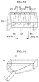
blowing unit 820 is not limited to the above-described configuration.Figs. 13 and14 are views schematically illustrating an example of other shapes of the blowing unit of an airflow generation unit. As illustrated inFig. 13 , ablowing unit 820a includes a plurality ofnozzles 822 which are arranged in a line in a width direction of themesh belt 46. The airflow generated by theblower 810 is discharged from thenozzles 822 of theblowing unit 820a through apipe 815. - In addition, as illustrated in
Fig. 14 , in ablowing unit 820b, a plurality ofpartition walls 825 partitioning the internal space and theopening portion 821 of theblowing unit 820b in a width direction of themesh belt 46 is provided. For example, at least a part of thepartition walls 825 is formed by a filter, a mesh, or the like. Accordingly, it is configured so as to allow air to pass therethrough. In any of the space portions partitioned by thepartition walls 825, apipe 815a for introducing an airflow generated by theblower 810 is provided. In the example illustrated inFig. 14 , theblowing unit 820b is partitioned into five space portions by the fourpartition walls 825.Pipes 815a are provided in the two space portions (each of second portions from both the end portions) among them. Theopening portion 821 is divided into openingportions 821a corresponding to the space portions in which thepipes 815a are provided and openingportions 821b corresponding to the space portions in which thepipes 815a are not provided. Airflows flown from thepipes 815a are directly discharged from the openingportions 821a, and airflows flown from thepipes 815a and then passed through thepartition walls 825 are discharged from the openingportions 821b. Accordingly, the flow rate of the airflows discharged from the openingportions 821b becomes lower (intensity becomes weak) compared to the flow rate of the airflow discharged from the openingportions 821a. Therefore, the intensity difference between the airflows occurs in a width direction of the mesh belt 46 (width direction of the web V). Accordingly, the web V can be easily divided in a direction approximately parallel to the transporting direction of the web V. - In addition, as illustrated in
Fig. 11 , theairflow generation unit 800 is set so as to apply an airflow to the deposition surface at an acute angle. An angle θa formed of a direction of the airflow discharged from theopening portion 821 and the deposition surface of themesh belt 46 applied to thetension roller 47a is 0° or greater and less than 90°, and more preferably 0° to 60°. Accordingly, the web V deposited to themesh belt 46 can be efficiently peeled from the deposition surface. - In addition, in the present embodiment, the moisture content of the airflow applied to the
mesh belt 46 by theairflow generation unit 800 is adjusted. Theairflow generation unit 800 includes a moisture-adjustingunit 880. The moisture-adjustingunit 880 is connected to thepipe 815 in which the airflow from theblower 810 is sent to theblowing unit 820, through apipe 881. The moisture-adjustingunit 880 can adjust the humidity of the airflow generated by theblower 810 by releasing the humidity (moisture) into the air. The relative humidity of the airflow is adjusted, for example, at a range of 50% to 70%. The airflow of which the humidity is adjusted is discharged from theopening portion 821 of theblowing unit 820 and then applied to the deposition surface of themesh belt 46 or the web V. Accordingly, electrostatic charges of the web V and themesh belt 46 are suppressed. The web V can be easily peeled from themesh belt 46. The moisture-adjustingunit 880 may be a humidifying unit which increases the humidity. - The
blower 56 configuring the suction unit is divided by suction of the web V and forms the subdividedbodies 11. That is, theblower 56 generates an airflow for suction of the peeled web V. The speed of the airflow generated by theblower 56 is set to be faster than the moving speed of the mesh belt 46 (transporting speed of the web V). For example, the speed of the airflow generated by theblower 56 is set to be 10 times or more faster than the moving speed of themesh belt 46. Accordingly, by the speed difference between the speed of the airflow generated by theblower 56 and the moving speed of themesh belt 46, the web V is torn along the width direction of the web V (direction intersecting a transporting direction of the web V), and the torn web V becomes thesubdivided bodies 11. The subdividedbodies 11 are transported to the blower 56 (deposition unit 60) side by the airflow. - In addition, the dividing
unit 180 includes asuction port unit 900 which is connected to theblower 56. Thesuction port unit 900 has asuction port 921 for suction (inhaling) of the subdividedbodies 11 by the airflow generated by theblower 56. Thesuction port 921 is provided in a position corresponding to the downstream side end of the web V in a transporting direction. For example, thesuction port 921 is arranged so as to face thetension roller 47a and arotary roller 49 on the downstream side of thetension roller 47a and therotary roller 49. Thesuction port unit 900 is connected to thepipe 7, thepipe 7 is connected to thepipe 54, and thepipe 54 is connected to theblower 56. Thesuction port unit 900 is arranged so as to be downward inclined from thesuction port 921 to thepipe 7, and thepipe 7 is arranged so as to be downward inclined to thepipe 54. The subdividedbodies 11 are sucked from thesuction port unit 900 by the airflow generated by theblower 56 and are transported to thedeposition unit 60 side through thepipe 7 and thepipe 54. -
Fig. 15 is a view schematically illustrating a suction port unit of a dividing unit according to the present embodiment. As illustrated inFig. 15 , thesuction port unit 900 includes asuction port 921 which is opened. Thesuction port 921 is formed in a rectangular slit shape. Thesuction port unit 900 is formed such that the opening area of the cross section in a direction crossing an airflow direction (direction parallel to the suction port 921) is gradually reduced from thesuction port 921 toward thepipe 7. Accordingly, it is possible to increase the speed of the airflow toward thepipe 7. Thesuction port 921 has a size allowing the subdividedbodies 11 to be sucked, and the length of the longitudinal direction is approximately the same as the width of themesh belt 46. - The shape of the
suction port unit 900 is not limited to the above-described configuration.Figs. 16 and 17 are views schematically illustrating an example of other shapes of the suction port unit of a dividing unit. As illustrated inFig. 16 , in asuction port unit 900a, a plurality ofpartition walls 925 partitioning thesuction port 921 in a width direction of themesh belt 46 is provided. Thepartition walls 925 have, for example, a thin planar shape. In the example illustrated inFig. 16 , foursuction ports 921a are formed by threepartition walls 925. The web V peeled from the deposition surface of themesh belt 46 by the airflow generated by theairflow generation unit 800 is sucked and divided by the airflow generated by theblower 56, and the divided web V becomes thesubdivided bodies 11. When the subdivided bodies 11 (web V) are sucked in thesuction port 921, the web V comes into contact with the front end portion (front edge portion) of thepartition walls 925 and is divided in a direction approximately parallel to the transporting direction (suction direction) of the web V. The web V becomes thesubdivided bodies 11 having a smaller volume, and is transported to thedeposition unit 60 side. - In addition, as illustrated in
Fig. 17 , a plurality ofpipes 7a is connected to thesuction port unit 900b. In the example illustrated inFig. 17 , threepipes 7a are provided in an equal interval. The plurality ofpipes 7a are joined and connected to onepipe 54. The subdivided bodies 11 (web V) sucked from thesuction port 921 are sucked in eachpipe 7a, and divided in a direction approximately parallel to the transporting direction (suction direction) of the web V. - In addition, as illustrated in
Fig. 11 , the firstweb forming unit 45 has atension roller 47a which is used as a supporting unit supporting themesh belt 46 having a deposition surface and arotary roller 49 facing thetension roller 47a across themesh belts 46. Therotary roller 49 is arranged so as to come into contact with asealing unit 991 which is provided in awall portion 990 disposed on the upper side of thesuction port unit 900. Accordingly, the vicinity of thesuction port 921 is substantially sealed. The web V deposited in the deposition surface of themesh belt 46 is nipped by thetension roller 47a and therotary roller 49 through themesh belt 46. In addition, theairflow generation unit 800 configuring thepeeling unit 310 applies the airflow generated by theblower 810 to the deposition surface of themesh belt 46 on a further downstream side of the web V further in a transporting direction than thetension roller 47a, and peels the web V from the deposition surface. Since the web V is nipped by thetension roller 47a and therotary roller 49, the web V in the further downstream side portion of a transporting direction of the web V than the nipped position can be peeled. That is, the position where the web V is peeled from the deposition surface of themesh belt 46 is stabilized, and the amount (length) of the peeled web V becomes uniform. Theblower 56 configuring thedividing unit 180 suctions the peeled web V and divides the sucked web V, and forms the subdividedbodies 11. Accordingly, the variation of the volume of the subdividedbodies 11 transported to thedeposition unit 60 can be reduced. - In addition, in the
sheet manufacturing apparatus 600 according to the present embodiment, an air volume caused by theblower 56 is set so as to be greater than the air volume caused by theairflow generation unit 800. A firstflow velocity sensor 840 for measuring the flow velocity of the airflow by theairflow generation unit 800 and a secondflow velocity sensor 940 for measuring the flow velocity of the airflow by theblower 56 are provided. In the present embodiment, the firstflow velocity sensor 840 is disposed in ablowing unit 820, and the secondflow velocity sensor 940 is disposed in thesuction port unit 900. The firstflow velocity sensor 840 and the secondflow velocity sensor 940 can be applied to, for example, a hot-wire flow velocity sensor. The sensor is not limited to the hot-wire flow velocity sensor and, for example, the sensor is applied to various flow velocity sensors which use a vane-type (Biram's) flow meter, a laser beam, a ultrasonic wave, or a microwave. - The first and second
flow velocity sensors control unit 140. In thecontrol unit 140, the air volume caused by the airflow in theblowing unit 820 and the air volume caused by the airflow in thesuction port unit 900 are calculated based on measuring data by the first and secondflow velocity sensors blower 810 and theblower 56 are controlled so that the air volume caused by theblower 56 is set to be greater than the air volume caused by theairflow generation unit 800 compared to the air volume of the both airflows. Specifically, a driving motor of theblower 810 or a driving motor of theblower 56 is controlled. Accordingly, dispersion or the like of the defibrated materials by the airflow discharged from theblowing unit 820 is suppressed, and the subdividedbodies 11 can be sucked in thesuction port unit 900. Since the basic configuration of thecontrol unit 140 is the same as the configuration of the first embodiment, the description thereof will be omitted. - According to the above-mentioned embodiments, the following effects can be obtained.
- The first screened material passing through the opening of the
screening unit 40 is deposited on themesh belt 46 to form the web V. The web V is transported to themesh belt 46 in a state where the web V is nipped by thetension roller 47a and therotary roller 49. The airflow caused by theairflow generation unit 800 is applied to the deposition surface of themesh belt 46 on a further downstream side of the web V in a transporting direction than thetension roller 47a. Accordingly, the web V, which is positioned on the further downstream side in the transporting direction than the portion nipped by thetension roller 47a and therotary roller 49, is peeled from themesh belt 46. The suction force by theblower 56 acts on the peeled web V. Accordingly, the peeled web V is divided to form the subdividedbodies 11, and is transported to the mixing unit 50 (deposition unit 60) side. Thus, in thesheet manufacturing apparatus 600, it is possible to suppress that the plurality of the defibrated materials are supplied to thedeposition unit 60 in a state where the plurality of the defibrated materials are entangled together and then become a large lump and to suppress that meshes of thedeposition unit 60 are clogged. Thus, in thesheet manufacturing apparatus 600, it is possible to manufacture the sheet S having high uniformity in density and thickness. - Next, a sheet manufacturing apparatus according to a fourth embodiment will be described with reference to the drawings.
Fig. 18 is a view schematically illustrating asheet manufacturing apparatus 700 according to the fourth embodiment. Hereinafter, in thesheet manufacturing apparatus 700, points different from the example of the above-describedsheet manufacturing apparatus 600 will be described and description of the same points will be omitted. - As illustrated in
Fig. 18 , asheet manufacturing apparatus 700 includes theairflow generation unit 800 configuring thepeeling unit 310, and a suction unit (blower 56 in the present embodiment) configuring thedividing unit 180, and therotary body 110. In the present embodiment, the dividingunit 180 is different from thesheet manufacturing apparatus 600 described above in that the dividingunit 180 includes therotary body 110. - The
rotary body 110 includes aprotrusion unit 114 for forming the subdividedbodies 11 by coming into contact with the web V and then dividing itself. In the present embodiment, therotary body 110 is an inner part of thesuction port unit 900, and is provided in the vicinity of thetension roller 47a. Therotary body 110 is provided in a position where theprotrusion unit 114 can come into contact with the web V peeled from themesh belt 46 by theairflow generation unit 800, and a position which does not comes into contact with themesh belt 46. Therotary body 110 is disposed in a position apart from themesh belt 46 so that the airflow discharged from theblowing unit 820 can be passed through between the tip end portion of theprotrusion unit 114 and the deposition surface of themesh belt 46. -
Fig. 19 is a view schematically illustrating a rotary body according to the present embodiment. As illustrated inFig. 19 , therotary body 110 has abase unit 112 and a planar shapedprotrusion unit 114 protruding from thebase unit 112. In the illustrated example, the fourprotrusion units 114 are provided at equal intervals. Theprotrusion unit 114 can rotate around thebase unit 112. Thebase unit 112 extends to the web V in a width direction. The length in an extension direction of thebase unit 112 of the 114 is the same as the width of themesh belt 46. The number of theprotrusion units 114 is not specifically limited and may be, for example, two. - The shape of the
rotary body 110 is not limited to the above-mentioned configuration.Figs. 20 and 21 are views schematically illustrating an example of other shapes of the rotary body. As illustrated inFig. 20 , therotary body 110a has abase unit 112 and aprotrusion unit 114a protruding from thebase unit 112. Here, a plurality ofprotrusion units 114a is arranged in an extension direction of thebase unit 112. A constant interval is provided between theadjacent protrusion units 114a. In a case of using therotary body 110a, since in the web V, a portion which comes into contact with theprotrusion units 114a and a portion which does not come into contact with theprotrusion units 114a occur in the width direction of therotary body 110a, the web V can be divided in a direction approximately parallel to the transporting direction. - In addition, as illustrated in
Fig. 21 , arotary body 110b has thebase unit 112 and theprotrusion unit 114b protruding from thebase unit 112. Here, the plurality ofprotrusion units 114b are disposed in an extension direction of thebase unit 112, and theadjacent protrusion units 114a are disposed in positions which are shifted by an angle of about 90° in a rotating direction. In a case of using therotary body 110b, since in the web V, a portion which comes into contact with theprotrusion units 114b and a portion which does not come into contact with theprotrusion units 114b occurs in the width direction of therotary body 110b, the web V can be divided in a direction approximately parallel to the transporting direction. - The shape of the
protrusion units sheet manufacturing apparatus 700 of the present embodiment, since the web V peeled by the airflow is divided, therotary body 110 can be disposed in a position separated from themesh belt 46 compared to thesheet manufacturing apparatus 100 of the first embodiment. Accordingly, the shape of the tip end portion of the protrusion unit 114 (114a and 114b) of a rotary body 111 is made in a sharp blade-shaped, and the web V can be easily divided. - The rotating direction of the
rotary body 110 can be appropriately set such as a discharging direction of the airflow caused by theairflow generation unit 800. In the present embodiment, the airflow caused by theairflow generation unit 800 is discharged from bottom to top. Accordingly, therotary body 110 is rotated in an arrow direction R3 (clockwise direction inFig. 18 ) along the discharging direction of the airflow caused by theairflow generation unit 800. Therefore, since the rotating direction of therotary body 110 does not go against the discharging direction of the airflow caused by theairflow generation unit 800, the driving load is reduced, and the web V can be easily divided. - In addition, in the
sheet manufacturing apparatus 700 of the present embodiment, the peripheral speed of therotary body 110 is set to be faster than the moving speed of the mesh belt 46 (transporting speed of the web V). For example, each of thetension roller 47 and therotary body 110 is provided with a speed detection sensor for detecting the rotating speed such as a rotary encoder (not illustrated). In thecontrol unit 140, by comparing the peripheral speed of therotary body 110 with the moving speed of themesh belt 46 based on the detection data obtained by the speed detection sensor, the peripheral speed of therotary body 110 is set so as to be faster than the moving speed of themesh belt 46, for example, the driving motor for rotating therotary body 110 is controlled. For example, in a case where the moving speed of themesh belt 46 is set to be in a range of 20 mm to 100 mm per second, the peripheral speed of therotary body 110 is controlled so as to be a speed which is two times or more the moving speed of the mesh belt. Accordingly, the web V can be more finely divided. Since the basic configuration of thecontrol unit 140 is the same as the configuration of the first embodiment, the description thereof will be omitted. - According to the above-mentioned embodiments, the following effects can be obtained.
- Even in a state where an amount of the air of the
blower 56 is suppressed, the subdividedbodies 11 can be formed by dividing the web V by therotary body 110. Accordingly, the energy consumption caused by theblower 56 can be reduced. - In the
airflow generation units 800 according to the third and fourth embodiments, the airflow is discharged toward themesh belt 46, and peels the web V from themesh belt 46, but the configuration is not limited thereto. For example, in theairflow generation unit 800, a configuration in which the web V is peeled from themesh belt 46 by suction of the air may be used. Even in this case, the same effect can be obtained. - Moreover, the sheet S manufactured by the sheet manufacturing apparatus of the invention mainly refers to those in a sheet shape. However, the sheet S is not limited to the sheet shape and may be a board shape or a web shape. In the present specification, the sheet is divided into paper and non-woven fabric. Paper includes aspects formed in a thin sheet shape using pulp and the waste paper as the raw material, and includes recording paper for writing or printing, wallpaper, wrapping paper, colored paper, drawing paper, Kent paper, and the like. Since non-woven fabric has a thickness thicker than that of paper or has strength lower than that of paper, the non-woven fabric includes general non-woven fabric, fiber board, tissue paper (tissue paper for cleaning), kitchen paper, cleaner, filter, liquid (waste ink and oil) absorption material, sound-absorbing material, thermal insulation material, cushioning material, mat, and the like. Furthermore, as the raw material, plant fibers such as cellulose, chemical fibers such as polyethylene terephthalate (PET) and polyester, and animal fibers such as wool and silk may be included.
- The invention omits a part of a configuration within a range having features and effects or may combine each embodiment and modification example. Moreover, the
manufacturing unit 102 omits a part of a configuration within a range in which the sheet can be manufactured, adds another configuration, or may be replaced with a known configuration. - The invention includes substantially the same configuration (for example, the same configuration in the function, the method, and the result or the same configuration in the object and the effect) as the configuration described in the embodiment. In addition, the invention includes configurations that replace non-essential portions of the configuration described in the embodiments. In addition, the invention includes configurations that can achieve the same operational effect or the same object as the configuration described in the embodiments. In addition, the invention includes configurations that are obtained by adding known techniques to the configuration described in the embodiments.
- The entire disclosure of Japanese Patent Application No.
2015-054415, filed March 18, 2015 2016-028632, filed February 18, 2016 - The foregoing description has been given by way of example only and it will be appreciated by a person skilled in the art that modifications can be made without departing from the scope of the present invention as defined by the claims.
Claims (18)
- A sheet manufacturing apparatus comprising:a defibrating unit configured to defibrate a raw material containing fiber into a defibrated material;a screening unit configured to screen the defibrated material that is defibrated by the defibrating unit;a web forming unit configured to form a web on which the defibrated material screened by the screening unit is deposited;a dividing unit configured to divide the web formed by the web forming unit to form a subdivided body;a deposition unit configured to deposit the defibrated material configuring the subdivided body; anda forming unit configured to form the sheet by pressurizing and heating the defibrated material deposited by the deposition unit.
- The sheet manufacturing apparatus according to Claim 1,
wherein the web forming unit comprises
a deposition surface on which the web is deposited; and
a peeling unit configured to peel the web deposited on the deposition surface from the deposition surface. - The sheet manufacturing apparatus according to Claim 2,
wherein the dividing unit includes a rotary body that includes a protrusion unit for forming the subdivided body by coming into contact with the web and then dividing itself. - The sheet manufacturing apparatus according to Claim 3,
wherein the web forming unit comprises a belt including the deposition surface and, at least two rollers by which the belt is stretched,
wherein the peeling unit comprises a stationary plate, and
wherein the stationary plate faces a roller among the rollers, which is positioned on the rotary body side, and comes into contact with the belt. - The sheet manufacturing apparatus according to Claim 3,
wherein the peeling unit comprises an airflow generation unit configured to generate airflow in a direction in which the web is separated from the belt in the vicinity of the rotary body. - The sheet manufacturing apparatus according to Claim 3,
wherein the web forming unit comprises a belt including the deposition surface, and
wherein the sheet manufacturing apparatus further comprises a control unit configured to control a rotational speed of the rotary body in compliance with a moving speed of the mesh belt. - The sheet manufacturing apparatus according to Claim 6, further comprising:a detection unit configured to detect a thickness of the web,wherein the control unit configured to control the moving speed of the belt based on the thickness of the web detected by the detection unit.
- The sheet manufacturing apparatus according to Claim 3,
a detection unit configured to detect a thickness of the web; and
a control unit configured to control a rotational speed of the rotary body based on a thickness of the web detected by the detection unit. - The sheet manufacturing apparatus according to Claim 2,
wherein the peeling unit comprises an airflow generation unit, and peels the web from the deposition surface by an airflow generated by the airflow generation unit. - The sheet manufacturing apparatus according to Claim 9,
wherein the airflow generation unit configured to apply an airflow to the deposition surface at an acute angle. - The sheet manufacturing apparatus according to Claim 9,
wherein the web peeled from the deposition surface by the airflow generated by the airflow generation unit is divided in a direction approximately parallel to the transporting direction of the web. - The sheet manufacturing apparatus according to Claim 10,
wherein the moisture content of the airflow applied to the deposition surface is adjusted. - The sheet manufacturing apparatus according to Claim 9,
wherein the dividing unit includes a suction unit for forming the subdivided body by suctioning the web and then dividing itself. - The sheet manufacturing apparatus according to Claim 13,
wherein the web forming unit comprises a belt including the deposition surface, a supporting unit which supports the belt, and a rotary roller which faces the supporting unit across the belt,
wherein the web decomposed in the deposition surface is nipped by the supporting unit and the rotary roller,
wherein the peeling unit peels the web from the deposition surface by applying the airflow generated by the airflow generation unit to the deposition surface, on a downstream side of the web further in a transporting direction than the supporting unit, and
wherein the dividing unit suctions the web peeled by the peeling unit, by the suction unit. - The sheet manufacturing apparatus according to Claim 13,
wherein an air volume caused by the suction unit is greater than an air volume caused by the airflow generation unit. - The sheet manufacturing apparatus according to Claim 1, further comprising:a supply unit configured to supply an additive agent to the subdivided body.
- The sheet manufacturing apparatus according to Claim 2,
wherein the web forming unit comprises
a mesh belt on which the web is deposited; and
a suction unit configured to suction the defibrated material screened by the screening unit from a surface opposite to a surface of the mesh belt on which the web is deposited. - A sheet manufacturing method comprising:defibrating a raw material containing fiber into a defibrated material;screening the defibrated material that is defibrated;forming a web on which a screened defibrated material is deposited;forming a subdivided body by dividing the web;depositing the defibrated material configuring the subdivided body; andforming a sheet by pressurizing and heating a deposited defibrated material.
Priority Applications (1)
| Application Number | Priority Date | Filing Date | Title |
|---|---|---|---|
| EP17196012.3A EP3299517B1 (en) | 2015-03-18 | 2016-03-16 | Sheet manufacturing apparatus and sheet manufacturing method |
Applications Claiming Priority (2)
| Application Number | Priority Date | Filing Date | Title |
|---|---|---|---|
| JP2015054415 | 2015-03-18 | ||
| JP2016028632A JP6733209B2 (en) | 2015-03-18 | 2016-02-18 | Sheet manufacturing equipment |
Related Child Applications (2)
| Application Number | Title | Priority Date | Filing Date |
|---|---|---|---|
| EP17196012.3A Division-Into EP3299517B1 (en) | 2015-03-18 | 2016-03-16 | Sheet manufacturing apparatus and sheet manufacturing method |
| EP17196012.3A Division EP3299517B1 (en) | 2015-03-18 | 2016-03-16 | Sheet manufacturing apparatus and sheet manufacturing method |
Publications (2)
| Publication Number | Publication Date |
|---|---|
| EP3070202A1 true EP3070202A1 (en) | 2016-09-21 |
| EP3070202B1 EP3070202B1 (en) | 2017-12-06 |
Family
ID=55542547
Family Applications (2)
| Application Number | Title | Priority Date | Filing Date |
|---|---|---|---|
| EP16160782.5A Active EP3070202B1 (en) | 2015-03-18 | 2016-03-16 | Sheet manufacturing apparatus and sheet manufacturing method |
| EP17196012.3A Active EP3299517B1 (en) | 2015-03-18 | 2016-03-16 | Sheet manufacturing apparatus and sheet manufacturing method |
Family Applications After (1)
| Application Number | Title | Priority Date | Filing Date |
|---|---|---|---|
| EP17196012.3A Active EP3299517B1 (en) | 2015-03-18 | 2016-03-16 | Sheet manufacturing apparatus and sheet manufacturing method |
Country Status (3)
| Country | Link |
|---|---|
| US (2) | US9771685B2 (en) |
| EP (2) | EP3070202B1 (en) |
| CN (1) | CN105986496B (en) |
Cited By (2)
| Publication number | Priority date | Publication date | Assignee | Title |
|---|---|---|---|---|
| EP3461947A1 (en) * | 2017-09-28 | 2019-04-03 | Seiko Epson Corporation | Sheet manufacturing apparatus |
| CN112342809A (en) * | 2020-11-04 | 2021-02-09 | 江西中竹生物质科技有限公司 | Ultrasonic office waste paper pulping process |
Families Citing this family (15)
| Publication number | Priority date | Publication date | Assignee | Title |
|---|---|---|---|---|
| TW201700831A (en) * | 2015-04-06 | 2017-01-01 | Seiko Epson Corp | Sheet manufacturing apparatus and sheet manufacturing method |
| JP6531871B2 (en) * | 2016-08-31 | 2019-06-19 | セイコーエプソン株式会社 | Sheet manufacturing apparatus and control method of sheet manufacturing apparatus |
| US11015273B2 (en) | 2016-11-29 | 2021-05-25 | Seiko Epson Corporation | Web forming device and sheet manufacturing apparatus |
| JP7083811B2 (en) * | 2017-03-24 | 2022-06-13 | 住友重機械工業株式会社 | Control device |
| JP6988277B2 (en) * | 2017-08-31 | 2022-01-05 | セイコーエプソン株式会社 | Sheet manufacturing equipment |
| JP7035551B2 (en) * | 2018-01-18 | 2022-03-15 | セイコーエプソン株式会社 | Fiber processing equipment, fiber raw material recycling equipment, and control method of fiber processing equipment |
| JP7006293B2 (en) * | 2018-01-18 | 2022-01-24 | セイコーエプソン株式会社 | Fiber processing equipment |
| TWI720414B (en) * | 2018-01-30 | 2021-03-01 | 日商精工愛普生股份有限公司 | Sheet manufacturing device and sheet manufacturing method |
| JP7119622B2 (en) * | 2018-06-18 | 2022-08-17 | セイコーエプソン株式会社 | Web forming equipment and sheet manufacturing equipment |
| JP7172518B2 (en) * | 2018-11-30 | 2022-11-16 | セイコーエプソン株式会社 | Fiber deposition device and sheet manufacturing device |
| JP7275609B2 (en) * | 2019-01-31 | 2023-05-18 | セイコーエプソン株式会社 | Separation device and fibrous body deposition device |
| JP2021085129A (en) * | 2019-11-29 | 2021-06-03 | セイコーエプソン株式会社 | Method and apparatus for forming fiber body, and a sheet |
| JP7194719B2 (en) * | 2020-10-28 | 2022-12-22 | 本田技研工業株式会社 | Material layer forming device |
| CN112900128B (en) * | 2021-02-09 | 2023-07-04 | 马兆旭 | Production process of paper and tableware |
| JP7838278B2 (en) * | 2022-01-07 | 2026-04-01 | セイコーエプソン株式会社 | Fiber manufacturing apparatus and defibration apparatus |
Citations (2)
| Publication number | Priority date | Publication date | Assignee | Title |
|---|---|---|---|---|
| JP2012144819A (en) | 2011-01-12 | 2012-08-02 | Seiko Epson Corp | Paper recycling apparatus and paper recycling method |
| EP2784210A1 (en) * | 2013-03-27 | 2014-10-01 | Seiko Epson Corporation | Sheet manufacturing apparatus and method for manufacturing sheet |
Family Cites Families (8)
| Publication number | Priority date | Publication date | Assignee | Title |
|---|---|---|---|---|
| US5316601A (en) * | 1990-10-25 | 1994-05-31 | Absorbent Products, Inc. | Fiber blending system |
| KR20130056867A (en) * | 2010-04-13 | 2013-05-30 | 쓰리엠 이노베이티브 프로퍼티즈 캄파니 | Inorganic fiber webs and methods of making and using |
| DE102010026178A1 (en) * | 2010-07-06 | 2012-01-12 | Tews Elektronik Gmbh & Co. Kg | Apparatus for the production of cigarettes in the tobacco processing industry and a method for this purpose |
| EP2664708B1 (en) | 2011-01-12 | 2017-04-12 | Seiko Epson Corporation | Paper recycling system and paper recycling process |
| JP2014208925A (en) * | 2013-03-27 | 2014-11-06 | セイコーエプソン株式会社 | Sheet manufacturing apparatus |
| JP2014208923A (en) * | 2013-03-27 | 2014-11-06 | セイコーエプソン株式会社 | Sheet manufacturing apparatus |
| JP6263931B2 (en) | 2013-10-01 | 2018-01-24 | セイコーエプソン株式会社 | Sheet manufacturing apparatus and sheet manufacturing method |
| JP6127882B2 (en) | 2013-10-01 | 2017-05-17 | セイコーエプソン株式会社 | Sheet manufacturing apparatus and sheet manufacturing method |
-
2016
- 2016-03-16 EP EP16160782.5A patent/EP3070202B1/en active Active
- 2016-03-16 US US15/071,356 patent/US9771685B2/en active Active
- 2016-03-16 EP EP17196012.3A patent/EP3299517B1/en active Active
- 2016-03-17 CN CN201610152941.6A patent/CN105986496B/en active Active
-
2017
- 2017-08-25 US US15/686,237 patent/US10081913B2/en active Active
Patent Citations (2)
| Publication number | Priority date | Publication date | Assignee | Title |
|---|---|---|---|---|
| JP2012144819A (en) | 2011-01-12 | 2012-08-02 | Seiko Epson Corp | Paper recycling apparatus and paper recycling method |
| EP2784210A1 (en) * | 2013-03-27 | 2014-10-01 | Seiko Epson Corporation | Sheet manufacturing apparatus and method for manufacturing sheet |
Cited By (3)
| Publication number | Priority date | Publication date | Assignee | Title |
|---|---|---|---|---|
| EP3461947A1 (en) * | 2017-09-28 | 2019-04-03 | Seiko Epson Corporation | Sheet manufacturing apparatus |
| US10914034B2 (en) | 2017-09-28 | 2021-02-09 | Seiko Epson Corporation | Sheet manufacturing apparatus |
| CN112342809A (en) * | 2020-11-04 | 2021-02-09 | 江西中竹生物质科技有限公司 | Ultrasonic office waste paper pulping process |
Also Published As
| Publication number | Publication date |
|---|---|
| US20170350073A1 (en) | 2017-12-07 |
| EP3070202B1 (en) | 2017-12-06 |
| EP3299517A1 (en) | 2018-03-28 |
| US9771685B2 (en) | 2017-09-26 |
| CN105986496A (en) | 2016-10-05 |
| CN105986496B (en) | 2020-03-06 |
| US10081913B2 (en) | 2018-09-25 |
| US20160273164A1 (en) | 2016-09-22 |
| EP3299517B1 (en) | 2019-05-15 |
Similar Documents
| Publication | Publication Date | Title |
|---|---|---|
| EP3070202B1 (en) | Sheet manufacturing apparatus and sheet manufacturing method | |
| JP6733209B2 (en) | Sheet manufacturing equipment | |
| JP6733779B2 (en) | Sheet manufacturing apparatus and method for controlling sheet manufacturing apparatus | |
| CN108699741B (en) | Sheet manufacturing equipment | |
| JP6747509B2 (en) | Sheet manufacturing apparatus and method for controlling sheet manufacturing apparatus | |
| JP6798485B2 (en) | Sheet manufacturing equipment | |
| JP6617405B2 (en) | Sheet manufacturing apparatus and sheet manufacturing method | |
| JP2016141031A (en) | Sheet manufacturing apparatus and sheet manufacturing method | |
| EP2980294A1 (en) | Sheet-manufacturing device and method for controlling sheet-manufacturing device | |
| US20160145802A1 (en) | Sheet manufacturing apparatus | |
| JP6798486B2 (en) | Sheet manufacturing equipment and sheet manufacturing method | |
| JP6816472B2 (en) | Sheet manufacturing equipment and control method of sheet manufacturing equipment | |
| EP3591109B1 (en) | Sheet manufacturing device, method for controlling same, and sheet manufacturing method | |
| JP6519337B2 (en) | Sheet manufacturing equipment | |
| JP6690656B2 (en) | Sheet manufacturing equipment | |
| JP7028173B2 (en) | Sheet manufacturing equipment | |
| JP2018115411A (en) | Sheet production apparatus and control method of sheet production apparatus | |
| JP6544477B2 (en) | Sheet manufacturing apparatus, sheet manufacturing method | |
| JP2017094525A (en) | Sheet manufacturing apparatus |
Legal Events
| Date | Code | Title | Description |
|---|---|---|---|
| PUAI | Public reference made under article 153(3) epc to a published international application that has entered the european phase |
Free format text: ORIGINAL CODE: 0009012 |
|
| AK | Designated contracting states |
Kind code of ref document: A1 Designated state(s): AL AT BE BG CH CY CZ DE DK EE ES FI FR GB GR HR HU IE IS IT LI LT LU LV MC MK MT NL NO PL PT RO RS SE SI SK SM TR |
|
| AX | Request for extension of the european patent |
Extension state: BA ME |
|
| 17P | Request for examination filed |
Effective date: 20170321 |
|
| RBV | Designated contracting states (corrected) |
Designated state(s): AL AT BE BG CH CY CZ DE DK EE ES FI FR GB GR HR HU IE IS IT LI LT LU LV MC MK MT NL NO PL PT RO RS SE SI SK SM TR |
|
| GRAP | Despatch of communication of intention to grant a patent |
Free format text: ORIGINAL CODE: EPIDOSNIGR1 |
|
| INTG | Intention to grant announced |
Effective date: 20170510 |
|
| GRAS | Grant fee paid |
Free format text: ORIGINAL CODE: EPIDOSNIGR3 |
|
| GRAJ | Information related to disapproval of communication of intention to grant by the applicant or resumption of examination proceedings by the epo deleted |
Free format text: ORIGINAL CODE: EPIDOSDIGR1 |
|
| GRAL | Information related to payment of fee for publishing/printing deleted |
Free format text: ORIGINAL CODE: EPIDOSDIGR3 |
|
| INTC | Intention to grant announced (deleted) | ||
| GRAR | Information related to intention to grant a patent recorded |
Free format text: ORIGINAL CODE: EPIDOSNIGR71 |
|
| GRAA | (expected) grant |
Free format text: ORIGINAL CODE: 0009210 |
|
| INTG | Intention to grant announced |
Effective date: 20171026 |
|
| AK | Designated contracting states |
Kind code of ref document: B1 Designated state(s): AL AT BE BG CH CY CZ DE DK EE ES FI FR GB GR HR HU IE IS IT LI LT LU LV MC MK MT NL NO PL PT RO RS SE SI SK SM TR |
|
| REG | Reference to a national code |
Ref country code: GB Ref legal event code: FG4D |
|
| REG | Reference to a national code |
Ref country code: AT Ref legal event code: REF Ref document number: 952483 Country of ref document: AT Kind code of ref document: T Effective date: 20171215 Ref country code: CH Ref legal event code: EP |
|
| REG | Reference to a national code |
Ref country code: IE Ref legal event code: FG4D |
|
| REG | Reference to a national code |
Ref country code: DE Ref legal event code: R096 Ref document number: 602016000990 Country of ref document: DE |
|
| REG | Reference to a national code |
Ref country code: FR Ref legal event code: PLFP Year of fee payment: 3 |
|
| REG | Reference to a national code |
Ref country code: NL Ref legal event code: MP Effective date: 20171206 |
|
| REG | Reference to a national code |
Ref country code: LT Ref legal event code: MG4D |
|
| PG25 | Lapsed in a contracting state [announced via postgrant information from national office to epo] |
Ref country code: SE Free format text: LAPSE BECAUSE OF FAILURE TO SUBMIT A TRANSLATION OF THE DESCRIPTION OR TO PAY THE FEE WITHIN THE PRESCRIBED TIME-LIMIT Effective date: 20171206 Ref country code: FI Free format text: LAPSE BECAUSE OF FAILURE TO SUBMIT A TRANSLATION OF THE DESCRIPTION OR TO PAY THE FEE WITHIN THE PRESCRIBED TIME-LIMIT Effective date: 20171206 Ref country code: LT Free format text: LAPSE BECAUSE OF FAILURE TO SUBMIT A TRANSLATION OF THE DESCRIPTION OR TO PAY THE FEE WITHIN THE PRESCRIBED TIME-LIMIT Effective date: 20171206 Ref country code: ES Free format text: LAPSE BECAUSE OF FAILURE TO SUBMIT A TRANSLATION OF THE DESCRIPTION OR TO PAY THE FEE WITHIN THE PRESCRIBED TIME-LIMIT Effective date: 20171206 Ref country code: NO Free format text: LAPSE BECAUSE OF FAILURE TO SUBMIT A TRANSLATION OF THE DESCRIPTION OR TO PAY THE FEE WITHIN THE PRESCRIBED TIME-LIMIT Effective date: 20180306 |
|
| REG | Reference to a national code |
Ref country code: AT Ref legal event code: MK05 Ref document number: 952483 Country of ref document: AT Kind code of ref document: T Effective date: 20171206 |
|
| PG25 | Lapsed in a contracting state [announced via postgrant information from national office to epo] |
Ref country code: HR Free format text: LAPSE BECAUSE OF FAILURE TO SUBMIT A TRANSLATION OF THE DESCRIPTION OR TO PAY THE FEE WITHIN THE PRESCRIBED TIME-LIMIT Effective date: 20171206 Ref country code: LV Free format text: LAPSE BECAUSE OF FAILURE TO SUBMIT A TRANSLATION OF THE DESCRIPTION OR TO PAY THE FEE WITHIN THE PRESCRIBED TIME-LIMIT Effective date: 20171206 Ref country code: BG Free format text: LAPSE BECAUSE OF FAILURE TO SUBMIT A TRANSLATION OF THE DESCRIPTION OR TO PAY THE FEE WITHIN THE PRESCRIBED TIME-LIMIT Effective date: 20180306 Ref country code: RS Free format text: LAPSE BECAUSE OF FAILURE TO SUBMIT A TRANSLATION OF THE DESCRIPTION OR TO PAY THE FEE WITHIN THE PRESCRIBED TIME-LIMIT Effective date: 20171206 Ref country code: GR Free format text: LAPSE BECAUSE OF FAILURE TO SUBMIT A TRANSLATION OF THE DESCRIPTION OR TO PAY THE FEE WITHIN THE PRESCRIBED TIME-LIMIT Effective date: 20180307 |
|
| PG25 | Lapsed in a contracting state [announced via postgrant information from national office to epo] |
Ref country code: NL Free format text: LAPSE BECAUSE OF FAILURE TO SUBMIT A TRANSLATION OF THE DESCRIPTION OR TO PAY THE FEE WITHIN THE PRESCRIBED TIME-LIMIT Effective date: 20171206 |
|
| PG25 | Lapsed in a contracting state [announced via postgrant information from national office to epo] |
Ref country code: EE Free format text: LAPSE BECAUSE OF FAILURE TO SUBMIT A TRANSLATION OF THE DESCRIPTION OR TO PAY THE FEE WITHIN THE PRESCRIBED TIME-LIMIT Effective date: 20171206 Ref country code: SK Free format text: LAPSE BECAUSE OF FAILURE TO SUBMIT A TRANSLATION OF THE DESCRIPTION OR TO PAY THE FEE WITHIN THE PRESCRIBED TIME-LIMIT Effective date: 20171206 Ref country code: CZ Free format text: LAPSE BECAUSE OF FAILURE TO SUBMIT A TRANSLATION OF THE DESCRIPTION OR TO PAY THE FEE WITHIN THE PRESCRIBED TIME-LIMIT Effective date: 20171206 |
|
| PG25 | Lapsed in a contracting state [announced via postgrant information from national office to epo] |
Ref country code: PL Free format text: LAPSE BECAUSE OF FAILURE TO SUBMIT A TRANSLATION OF THE DESCRIPTION OR TO PAY THE FEE WITHIN THE PRESCRIBED TIME-LIMIT Effective date: 20171206 Ref country code: AT Free format text: LAPSE BECAUSE OF FAILURE TO SUBMIT A TRANSLATION OF THE DESCRIPTION OR TO PAY THE FEE WITHIN THE PRESCRIBED TIME-LIMIT Effective date: 20171206 Ref country code: SM Free format text: LAPSE BECAUSE OF FAILURE TO SUBMIT A TRANSLATION OF THE DESCRIPTION OR TO PAY THE FEE WITHIN THE PRESCRIBED TIME-LIMIT Effective date: 20171206 Ref country code: IT Free format text: LAPSE BECAUSE OF FAILURE TO SUBMIT A TRANSLATION OF THE DESCRIPTION OR TO PAY THE FEE WITHIN THE PRESCRIBED TIME-LIMIT Effective date: 20171206 Ref country code: RO Free format text: LAPSE BECAUSE OF FAILURE TO SUBMIT A TRANSLATION OF THE DESCRIPTION OR TO PAY THE FEE WITHIN THE PRESCRIBED TIME-LIMIT Effective date: 20171206 |
|
| REG | Reference to a national code |
Ref country code: DE Ref legal event code: R097 Ref document number: 602016000990 Country of ref document: DE |
|
| PLBE | No opposition filed within time limit |
Free format text: ORIGINAL CODE: 0009261 |
|
| STAA | Information on the status of an ep patent application or granted ep patent |
Free format text: STATUS: NO OPPOSITION FILED WITHIN TIME LIMIT |
|
| 26N | No opposition filed |
Effective date: 20180907 |
|
| PG25 | Lapsed in a contracting state [announced via postgrant information from national office to epo] |
Ref country code: SI Free format text: LAPSE BECAUSE OF FAILURE TO SUBMIT A TRANSLATION OF THE DESCRIPTION OR TO PAY THE FEE WITHIN THE PRESCRIBED TIME-LIMIT Effective date: 20171206 Ref country code: MC Free format text: LAPSE BECAUSE OF FAILURE TO SUBMIT A TRANSLATION OF THE DESCRIPTION OR TO PAY THE FEE WITHIN THE PRESCRIBED TIME-LIMIT Effective date: 20171206 Ref country code: DK Free format text: LAPSE BECAUSE OF FAILURE TO SUBMIT A TRANSLATION OF THE DESCRIPTION OR TO PAY THE FEE WITHIN THE PRESCRIBED TIME-LIMIT Effective date: 20171206 |
|
| REG | Reference to a national code |
Ref country code: BE Ref legal event code: MM Effective date: 20180331 |
|
| REG | Reference to a national code |
Ref country code: IE Ref legal event code: MM4A |
|
| PG25 | Lapsed in a contracting state [announced via postgrant information from national office to epo] |
Ref country code: LU Free format text: LAPSE BECAUSE OF NON-PAYMENT OF DUE FEES Effective date: 20180316 |
|
| PG25 | Lapsed in a contracting state [announced via postgrant information from national office to epo] |
Ref country code: IE Free format text: LAPSE BECAUSE OF NON-PAYMENT OF DUE FEES Effective date: 20180316 |
|
| PG25 | Lapsed in a contracting state [announced via postgrant information from national office to epo] |
Ref country code: BE Free format text: LAPSE BECAUSE OF NON-PAYMENT OF DUE FEES Effective date: 20180331 |
|
| REG | Reference to a national code |
Ref country code: CH Ref legal event code: PL |
|
| PG25 | Lapsed in a contracting state [announced via postgrant information from national office to epo] |
Ref country code: CH Free format text: LAPSE BECAUSE OF NON-PAYMENT OF DUE FEES Effective date: 20190331 Ref country code: MT Free format text: LAPSE BECAUSE OF NON-PAYMENT OF DUE FEES Effective date: 20180316 Ref country code: LI Free format text: LAPSE BECAUSE OF NON-PAYMENT OF DUE FEES Effective date: 20190331 |
|
| PG25 | Lapsed in a contracting state [announced via postgrant information from national office to epo] |
Ref country code: TR Free format text: LAPSE BECAUSE OF FAILURE TO SUBMIT A TRANSLATION OF THE DESCRIPTION OR TO PAY THE FEE WITHIN THE PRESCRIBED TIME-LIMIT Effective date: 20171206 |
|
| PG25 | Lapsed in a contracting state [announced via postgrant information from national office to epo] |
Ref country code: PT Free format text: LAPSE BECAUSE OF FAILURE TO SUBMIT A TRANSLATION OF THE DESCRIPTION OR TO PAY THE FEE WITHIN THE PRESCRIBED TIME-LIMIT Effective date: 20171206 |
|
| PG25 | Lapsed in a contracting state [announced via postgrant information from national office to epo] |
Ref country code: HU Free format text: LAPSE BECAUSE OF FAILURE TO SUBMIT A TRANSLATION OF THE DESCRIPTION OR TO PAY THE FEE WITHIN THE PRESCRIBED TIME-LIMIT; INVALID AB INITIO Effective date: 20160316 Ref country code: CY Free format text: LAPSE BECAUSE OF FAILURE TO SUBMIT A TRANSLATION OF THE DESCRIPTION OR TO PAY THE FEE WITHIN THE PRESCRIBED TIME-LIMIT Effective date: 20171206 Ref country code: MK Free format text: LAPSE BECAUSE OF NON-PAYMENT OF DUE FEES Effective date: 20171206 |
|
| PG25 | Lapsed in a contracting state [announced via postgrant information from national office to epo] |
Ref country code: AL Free format text: LAPSE BECAUSE OF FAILURE TO SUBMIT A TRANSLATION OF THE DESCRIPTION OR TO PAY THE FEE WITHIN THE PRESCRIBED TIME-LIMIT Effective date: 20171206 Ref country code: IS Free format text: LAPSE BECAUSE OF FAILURE TO SUBMIT A TRANSLATION OF THE DESCRIPTION OR TO PAY THE FEE WITHIN THE PRESCRIBED TIME-LIMIT Effective date: 20180406 |
|
| PGFP | Annual fee paid to national office [announced via postgrant information from national office to epo] |
Ref country code: GB Payment date: 20260202 Year of fee payment: 11 |
|
| PGFP | Annual fee paid to national office [announced via postgrant information from national office to epo] |
Ref country code: DE Payment date: 20260128 Year of fee payment: 11 |
|
| PGFP | Annual fee paid to national office [announced via postgrant information from national office to epo] |
Ref country code: FR Payment date: 20260209 Year of fee payment: 11 |