EP3070068A1 - Composite body, honeycomb structure, and method for producing composite body - Google Patents
Composite body, honeycomb structure, and method for producing composite body Download PDFInfo
- Publication number
- EP3070068A1 EP3070068A1 EP16161134.8A EP16161134A EP3070068A1 EP 3070068 A1 EP3070068 A1 EP 3070068A1 EP 16161134 A EP16161134 A EP 16161134A EP 3070068 A1 EP3070068 A1 EP 3070068A1
- Authority
- EP
- European Patent Office
- Prior art keywords
- oxide layer
- perovskite
- composite body
- base
- oxide
- Prior art date
- Legal status (The legal status is an assumption and is not a legal conclusion. Google has not performed a legal analysis and makes no representation as to the accuracy of the status listed.)
- Granted
Links
- 239000002131 composite material Substances 0.000 title claims abstract description 73
- 238000004519 manufacturing process Methods 0.000 title claims description 33
- 238000005304 joining Methods 0.000 claims abstract description 144
- 239000000843 powder Substances 0.000 claims description 102
- 229910052751 metal Inorganic materials 0.000 claims description 88
- 239000002184 metal Substances 0.000 claims description 83
- 239000002994 raw material Substances 0.000 claims description 70
- 238000010304 firing Methods 0.000 claims description 61
- 239000000919 ceramic Substances 0.000 claims description 45
- 150000001875 compounds Chemical class 0.000 claims description 32
- 229910045601 alloy Inorganic materials 0.000 claims description 25
- 239000000956 alloy Substances 0.000 claims description 25
- 229910002282 La2CuO4 Inorganic materials 0.000 claims description 17
- 238000000034 method Methods 0.000 claims description 16
- 229910002405 SrFeO3 Inorganic materials 0.000 claims description 15
- 229910020854 La(OH)3 Inorganic materials 0.000 claims description 14
- 229910052742 iron Inorganic materials 0.000 claims description 12
- 229910052802 copper Inorganic materials 0.000 claims description 11
- 229910000018 strontium carbonate Inorganic materials 0.000 claims description 11
- LEDMRZGFZIAGGB-UHFFFAOYSA-L strontium carbonate Chemical compound [Sr+2].[O-]C([O-])=O LEDMRZGFZIAGGB-UHFFFAOYSA-L 0.000 claims description 11
- BVKZGUZCCUSVTD-UHFFFAOYSA-L Carbonate Chemical compound [O-]C([O-])=O BVKZGUZCCUSVTD-UHFFFAOYSA-L 0.000 claims description 4
- 229910052746 lanthanum Inorganic materials 0.000 claims description 4
- XLYOFNOQVPJJNP-UHFFFAOYSA-M hydroxide Chemical compound [OH-] XLYOFNOQVPJJNP-UHFFFAOYSA-M 0.000 claims description 3
- 229910052712 strontium Inorganic materials 0.000 claims description 3
- VEXZGXHMUGYJMC-UHFFFAOYSA-M Chloride anion Chemical compound [Cl-] VEXZGXHMUGYJMC-UHFFFAOYSA-M 0.000 claims description 2
- 239000002585 base Substances 0.000 description 67
- 239000000463 material Substances 0.000 description 66
- XEEYBQQBJWHFJM-UHFFFAOYSA-N iron Substances [Fe] XEEYBQQBJWHFJM-UHFFFAOYSA-N 0.000 description 36
- 239000011148 porous material Substances 0.000 description 32
- HBMJWWWQQXIZIP-UHFFFAOYSA-N silicon carbide Chemical compound [Si+]#[C-] HBMJWWWQQXIZIP-UHFFFAOYSA-N 0.000 description 28
- 229910010271 silicon carbide Inorganic materials 0.000 description 28
- 239000012298 atmosphere Substances 0.000 description 25
- 239000010949 copper Substances 0.000 description 23
- 229910044991 metal oxide Inorganic materials 0.000 description 23
- 150000004706 metal oxides Chemical class 0.000 description 23
- 230000015572 biosynthetic process Effects 0.000 description 14
- PXHVJJICTQNCMI-UHFFFAOYSA-N Nickel Chemical compound [Ni] PXHVJJICTQNCMI-UHFFFAOYSA-N 0.000 description 11
- 239000002002 slurry Substances 0.000 description 11
- -1 for example Substances 0.000 description 10
- 239000010935 stainless steel Substances 0.000 description 10
- 229910001220 stainless steel Inorganic materials 0.000 description 10
- 238000002441 X-ray diffraction Methods 0.000 description 9
- 150000001768 cations Chemical class 0.000 description 9
- 238000005259 measurement Methods 0.000 description 9
- 230000003647 oxidation Effects 0.000 description 9
- 238000007254 oxidation reaction Methods 0.000 description 9
- 239000002245 particle Substances 0.000 description 9
- GWEVSGVZZGPLCZ-UHFFFAOYSA-N titanium dioxide Inorganic materials O=[Ti]=O GWEVSGVZZGPLCZ-UHFFFAOYSA-N 0.000 description 9
- 229910052759 nickel Inorganic materials 0.000 description 8
- 238000006243 chemical reaction Methods 0.000 description 7
- 239000000203 mixture Substances 0.000 description 7
- 239000002904 solvent Substances 0.000 description 7
- 229910052723 transition metal Inorganic materials 0.000 description 7
- 150000003624 transition metals Chemical class 0.000 description 7
- QPLDLSVMHZLSFG-UHFFFAOYSA-N Copper oxide Chemical compound [Cu]=O QPLDLSVMHZLSFG-UHFFFAOYSA-N 0.000 description 6
- 229910052581 Si3N4 Inorganic materials 0.000 description 6
- 239000011230 binding agent Substances 0.000 description 6
- 230000008859 change Effects 0.000 description 5
- 238000010586 diagram Methods 0.000 description 5
- 238000010438 heat treatment Methods 0.000 description 5
- 229910010272 inorganic material Inorganic materials 0.000 description 5
- 239000011147 inorganic material Substances 0.000 description 5
- 239000001301 oxygen Substances 0.000 description 5
- 229910052760 oxygen Inorganic materials 0.000 description 5
- 238000003786 synthesis reaction Methods 0.000 description 5
- VTYYLEPIZMXCLO-UHFFFAOYSA-L Calcium carbonate Chemical compound [Ca+2].[O-]C([O-])=O VTYYLEPIZMXCLO-UHFFFAOYSA-L 0.000 description 4
- MCMNRKCIXSYSNV-UHFFFAOYSA-N Zirconium dioxide Chemical compound O=[Zr]=O MCMNRKCIXSYSNV-UHFFFAOYSA-N 0.000 description 4
- 238000000498 ball milling Methods 0.000 description 4
- 239000013078 crystal Substances 0.000 description 4
- 239000007789 gas Substances 0.000 description 4
- 238000000227 grinding Methods 0.000 description 4
- JEIPFZHSYJVQDO-UHFFFAOYSA-N iron(III) oxide Inorganic materials O=[Fe]O[Fe]=O JEIPFZHSYJVQDO-UHFFFAOYSA-N 0.000 description 4
- 229910052748 manganese Inorganic materials 0.000 description 4
- NUJOXMJBOLGQSY-UHFFFAOYSA-N manganese dioxide Chemical compound O=[Mn]=O NUJOXMJBOLGQSY-UHFFFAOYSA-N 0.000 description 4
- 239000011812 mixed powder Substances 0.000 description 4
- 238000002156 mixing Methods 0.000 description 4
- 229910003465 moissanite Inorganic materials 0.000 description 4
- 229910052574 oxide ceramic Inorganic materials 0.000 description 4
- 239000011224 oxide ceramic Substances 0.000 description 4
- 229920002037 poly(vinyl butyral) polymer Polymers 0.000 description 4
- XLYOFNOQVPJJNP-UHFFFAOYSA-N water Substances O XLYOFNOQVPJJNP-UHFFFAOYSA-N 0.000 description 4
- 229910019589 Cr—Fe Inorganic materials 0.000 description 3
- LYCAIKOWRPUZTN-UHFFFAOYSA-N Ethylene glycol Chemical compound OCCO LYCAIKOWRPUZTN-UHFFFAOYSA-N 0.000 description 3
- 229910003271 Ni-Fe Inorganic materials 0.000 description 3
- FAPWRFPIFSIZLT-UHFFFAOYSA-M Sodium chloride Chemical compound [Na+].[Cl-] FAPWRFPIFSIZLT-UHFFFAOYSA-M 0.000 description 3
- QVGXLLKOCUKJST-UHFFFAOYSA-N atomic oxygen Chemical compound [O] QVGXLLKOCUKJST-UHFFFAOYSA-N 0.000 description 3
- 239000007795 chemical reaction product Substances 0.000 description 3
- 238000005336 cracking Methods 0.000 description 3
- 230000032798 delamination Effects 0.000 description 3
- 239000002612 dispersion medium Substances 0.000 description 3
- 238000001125 extrusion Methods 0.000 description 3
- 239000000446 fuel Substances 0.000 description 3
- 229910000856 hastalloy Inorganic materials 0.000 description 3
- 238000005470 impregnation Methods 0.000 description 3
- 229910000833 kovar Inorganic materials 0.000 description 3
- MRELNEQAGSRDBK-UHFFFAOYSA-N lanthanum oxide Inorganic materials [O-2].[O-2].[O-2].[La+3].[La+3] MRELNEQAGSRDBK-UHFFFAOYSA-N 0.000 description 3
- 239000011572 manganese Substances 0.000 description 3
- 150000004767 nitrides Chemical class 0.000 description 3
- 239000012299 nitrogen atmosphere Substances 0.000 description 3
- 238000009828 non-uniform distribution Methods 0.000 description 3
- 230000001590 oxidative effect Effects 0.000 description 3
- KTUFCUMIWABKDW-UHFFFAOYSA-N oxo(oxolanthaniooxy)lanthanum Chemical compound O=[La]O[La]=O KTUFCUMIWABKDW-UHFFFAOYSA-N 0.000 description 3
- 239000006104 solid solution Substances 0.000 description 3
- 238000009864 tensile test Methods 0.000 description 3
- 239000010936 titanium Substances 0.000 description 3
- 229910003042 (La,Sr)MnO3 Inorganic materials 0.000 description 2
- 229910000505 Al2TiO5 Inorganic materials 0.000 description 2
- 229910052580 B4C Inorganic materials 0.000 description 2
- 229910001374 Invar Inorganic materials 0.000 description 2
- UQSXHKLRYXJYBZ-UHFFFAOYSA-N Iron oxide Chemical compound [Fe]=O UQSXHKLRYXJYBZ-UHFFFAOYSA-N 0.000 description 2
- 229910002221 La2NiO4 Inorganic materials 0.000 description 2
- 229910002262 LaCrO3 Inorganic materials 0.000 description 2
- 229910002328 LaMnO3 Inorganic materials 0.000 description 2
- 229910002340 LaNiO3 Inorganic materials 0.000 description 2
- 229910020968 MoSi2 Inorganic materials 0.000 description 2
- 239000004677 Nylon Substances 0.000 description 2
- VYPSYNLAJGMNEJ-UHFFFAOYSA-N Silicium dioxide Chemical compound O=[Si]=O VYPSYNLAJGMNEJ-UHFFFAOYSA-N 0.000 description 2
- 229910002370 SrTiO3 Inorganic materials 0.000 description 2
- NRTOMJZYCJJWKI-UHFFFAOYSA-N Titanium nitride Chemical compound [Ti]#N NRTOMJZYCJJWKI-UHFFFAOYSA-N 0.000 description 2
- 229910021536 Zeolite Inorganic materials 0.000 description 2
- 229910026551 ZrC Inorganic materials 0.000 description 2
- OTCHGXYCWNXDOA-UHFFFAOYSA-N [C].[Zr] Chemical compound [C].[Zr] OTCHGXYCWNXDOA-UHFFFAOYSA-N 0.000 description 2
- 229910052783 alkali metal Inorganic materials 0.000 description 2
- 150000001340 alkali metals Chemical class 0.000 description 2
- 229910052784 alkaline earth metal Inorganic materials 0.000 description 2
- 150000001342 alkaline earth metals Chemical class 0.000 description 2
- 229910052787 antimony Inorganic materials 0.000 description 2
- YXTPWUNVHCYOSP-UHFFFAOYSA-N bis($l^{2}-silanylidene)molybdenum Chemical compound [Si]=[Mo]=[Si] YXTPWUNVHCYOSP-UHFFFAOYSA-N 0.000 description 2
- INAHAJYZKVIDIZ-UHFFFAOYSA-N boron carbide Chemical compound B12B3B4C32B41 INAHAJYZKVIDIZ-UHFFFAOYSA-N 0.000 description 2
- 239000006227 byproduct Substances 0.000 description 2
- 238000001354 calcination Methods 0.000 description 2
- 229910000019 calcium carbonate Inorganic materials 0.000 description 2
- 239000004927 clay Substances 0.000 description 2
- 238000005049 combustion synthesis Methods 0.000 description 2
- PMHQVHHXPFUNSP-UHFFFAOYSA-M copper(1+);methylsulfanylmethane;bromide Chemical compound Br[Cu].CSC PMHQVHHXPFUNSP-UHFFFAOYSA-M 0.000 description 2
- 229910052878 cordierite Inorganic materials 0.000 description 2
- 238000000354 decomposition reaction Methods 0.000 description 2
- 230000027734 detection of oxygen Effects 0.000 description 2
- JSKIRARMQDRGJZ-UHFFFAOYSA-N dimagnesium dioxido-bis[(1-oxido-3-oxo-2,4,6,8,9-pentaoxa-1,3-disila-5,7-dialuminabicyclo[3.3.1]nonan-7-yl)oxy]silane Chemical compound [Mg++].[Mg++].[O-][Si]([O-])(O[Al]1O[Al]2O[Si](=O)O[Si]([O-])(O1)O2)O[Al]1O[Al]2O[Si](=O)O[Si]([O-])(O1)O2 JSKIRARMQDRGJZ-UHFFFAOYSA-N 0.000 description 2
- HNPSIPDUKPIQMN-UHFFFAOYSA-N dioxosilane;oxo(oxoalumanyloxy)alumane Chemical compound O=[Si]=O.O=[Al]O[Al]=O HNPSIPDUKPIQMN-UHFFFAOYSA-N 0.000 description 2
- KZHJGOXRZJKJNY-UHFFFAOYSA-N dioxosilane;oxo(oxoalumanyloxy)alumane Chemical compound O=[Si]=O.O=[Si]=O.O=[Al]O[Al]=O.O=[Al]O[Al]=O.O=[Al]O[Al]=O KZHJGOXRZJKJNY-UHFFFAOYSA-N 0.000 description 2
- 239000002270 dispersing agent Substances 0.000 description 2
- 238000011156 evaluation Methods 0.000 description 2
- 238000011049 filling Methods 0.000 description 2
- 239000012530 fluid Substances 0.000 description 2
- 229910052737 gold Inorganic materials 0.000 description 2
- 229910001026 inconel Inorganic materials 0.000 description 2
- 229910052744 lithium Inorganic materials 0.000 description 2
- 239000000395 magnesium oxide Substances 0.000 description 2
- CPLXHLVBOLITMK-UHFFFAOYSA-N magnesium oxide Inorganic materials [Mg]=O CPLXHLVBOLITMK-UHFFFAOYSA-N 0.000 description 2
- AXZKOIWUVFPNLO-UHFFFAOYSA-N magnesium;oxygen(2-) Chemical compound [O-2].[Mg+2] AXZKOIWUVFPNLO-UHFFFAOYSA-N 0.000 description 2
- 150000001247 metal acetylides Chemical class 0.000 description 2
- 150000002736 metal compounds Chemical class 0.000 description 2
- 150000002739 metals Chemical class 0.000 description 2
- 229910021344 molybdenum silicide Inorganic materials 0.000 description 2
- 238000000465 moulding Methods 0.000 description 2
- 229910052863 mullite Inorganic materials 0.000 description 2
- 229910052758 niobium Inorganic materials 0.000 description 2
- 229910000510 noble metal Inorganic materials 0.000 description 2
- 229920001778 nylon Polymers 0.000 description 2
- TWNQGVIAIRXVLR-UHFFFAOYSA-N oxo(oxoalumanyloxy)alumane Chemical compound O=[Al]O[Al]=O TWNQGVIAIRXVLR-UHFFFAOYSA-N 0.000 description 2
- GNRSAWUEBMWBQH-UHFFFAOYSA-N oxonickel Chemical compound [Ni]=O GNRSAWUEBMWBQH-UHFFFAOYSA-N 0.000 description 2
- RVTZCBVAJQQJTK-UHFFFAOYSA-N oxygen(2-);zirconium(4+) Chemical compound [O-2].[O-2].[Zr+4] RVTZCBVAJQQJTK-UHFFFAOYSA-N 0.000 description 2
- 229910052697 platinum Inorganic materials 0.000 description 2
- AABBHSMFGKYLKE-SNAWJCMRSA-N propan-2-yl (e)-but-2-enoate Chemical compound C\C=C\C(=O)OC(C)C AABBHSMFGKYLKE-SNAWJCMRSA-N 0.000 description 2
- 229920005989 resin Polymers 0.000 description 2
- 239000011347 resin Substances 0.000 description 2
- 229910021332 silicide Inorganic materials 0.000 description 2
- HQVNEWCFYHHQES-UHFFFAOYSA-N silicon nitride Chemical compound N12[Si]34N5[Si]62N3[Si]51N64 HQVNEWCFYHHQES-UHFFFAOYSA-N 0.000 description 2
- 229910052814 silicon oxide Inorganic materials 0.000 description 2
- 238000005245 sintering Methods 0.000 description 2
- 229910052715 tantalum Inorganic materials 0.000 description 2
- 229910052719 titanium Inorganic materials 0.000 description 2
- OGIDPMRJRNCKJF-UHFFFAOYSA-N titanium oxide Inorganic materials [Ti]=O OGIDPMRJRNCKJF-UHFFFAOYSA-N 0.000 description 2
- MTPVUVINMAGMJL-UHFFFAOYSA-N trimethyl(1,1,2,2,2-pentafluoroethyl)silane Chemical compound C[Si](C)(C)C(F)(F)C(F)(F)F MTPVUVINMAGMJL-UHFFFAOYSA-N 0.000 description 2
- 229910052721 tungsten Inorganic materials 0.000 description 2
- 239000010457 zeolite Substances 0.000 description 2
- 229910052726 zirconium Inorganic materials 0.000 description 2
- ZVWKZXLXHLZXLS-UHFFFAOYSA-N zirconium nitride Chemical compound [Zr]#N ZVWKZXLXHLZXLS-UHFFFAOYSA-N 0.000 description 2
- 229910001928 zirconium oxide Inorganic materials 0.000 description 2
- 229910000166 zirconium phosphate Inorganic materials 0.000 description 2
- LEHFSLREWWMLPU-UHFFFAOYSA-B zirconium(4+);tetraphosphate Chemical compound [Zr+4].[Zr+4].[Zr+4].[O-]P([O-])([O-])=O.[O-]P([O-])([O-])=O.[O-]P([O-])([O-])=O.[O-]P([O-])([O-])=O LEHFSLREWWMLPU-UHFFFAOYSA-B 0.000 description 2
- WUOACPNHFRMFPN-SECBINFHSA-N (S)-(-)-alpha-terpineol Chemical compound CC1=CC[C@@H](C(C)(C)O)CC1 WUOACPNHFRMFPN-SECBINFHSA-N 0.000 description 1
- UXVMQQNJUSDDNG-UHFFFAOYSA-L Calcium chloride Chemical compound [Cl-].[Cl-].[Ca+2] UXVMQQNJUSDDNG-UHFFFAOYSA-L 0.000 description 1
- 229910052684 Cerium Inorganic materials 0.000 description 1
- 229910020598 Co Fe Inorganic materials 0.000 description 1
- 229910002519 Co-Fe Inorganic materials 0.000 description 1
- RYGMFSIKBFXOCR-UHFFFAOYSA-N Copper Chemical compound [Cu] RYGMFSIKBFXOCR-UHFFFAOYSA-N 0.000 description 1
- 229910017116 Fe—Mo Inorganic materials 0.000 description 1
- 229910002618 GdFeO3 Inorganic materials 0.000 description 1
- 206010021143 Hypoxia Diseases 0.000 description 1
- 229910002254 LaCoO3 Inorganic materials 0.000 description 1
- 229910002260 LaCuO3 Inorganic materials 0.000 description 1
- 229910002321 LaFeO3 Inorganic materials 0.000 description 1
- 229910018487 Ni—Cr Inorganic materials 0.000 description 1
- 229920002472 Starch Polymers 0.000 description 1
- OVKDFILSBMEKLT-UHFFFAOYSA-N alpha-Terpineol Natural products CC(=C)C1(O)CCC(C)=CC1 OVKDFILSBMEKLT-UHFFFAOYSA-N 0.000 description 1
- WUOACPNHFRMFPN-UHFFFAOYSA-N alpha-terpineol Chemical compound CC1=CCC(C(C)(C)O)CC1 WUOACPNHFRMFPN-UHFFFAOYSA-N 0.000 description 1
- 229940088601 alpha-terpineol Drugs 0.000 description 1
- 229910052782 aluminium Inorganic materials 0.000 description 1
- XAGFODPZIPBFFR-UHFFFAOYSA-N aluminium Chemical compound [Al] XAGFODPZIPBFFR-UHFFFAOYSA-N 0.000 description 1
- PNEYBMLMFCGWSK-UHFFFAOYSA-N aluminium oxide Inorganic materials [O-2].[O-2].[O-2].[Al+3].[Al+3] PNEYBMLMFCGWSK-UHFFFAOYSA-N 0.000 description 1
- 239000012300 argon atmosphere Substances 0.000 description 1
- 229910052788 barium Inorganic materials 0.000 description 1
- 229910002113 barium titanate Inorganic materials 0.000 description 1
- 230000008901 benefit Effects 0.000 description 1
- 229910052797 bismuth Inorganic materials 0.000 description 1
- 229910052793 cadmium Inorganic materials 0.000 description 1
- 239000001110 calcium chloride Substances 0.000 description 1
- 229910001628 calcium chloride Inorganic materials 0.000 description 1
- 239000003054 catalyst Substances 0.000 description 1
- 239000001913 cellulose Substances 0.000 description 1
- 229920002678 cellulose Polymers 0.000 description 1
- 229910010293 ceramic material Inorganic materials 0.000 description 1
- 229910052804 chromium Inorganic materials 0.000 description 1
- 239000000571 coke Substances 0.000 description 1
- 238000002485 combustion reaction Methods 0.000 description 1
- 230000000052 comparative effect Effects 0.000 description 1
- 230000008602 contraction Effects 0.000 description 1
- 230000002950 deficient Effects 0.000 description 1
- SQIFACVGCPWBQZ-UHFFFAOYSA-N delta-terpineol Natural products CC(C)(O)C1CCC(=C)CC1 SQIFACVGCPWBQZ-UHFFFAOYSA-N 0.000 description 1
- 238000000280 densification Methods 0.000 description 1
- 229910003460 diamond Inorganic materials 0.000 description 1
- 239000010432 diamond Substances 0.000 description 1
- 238000009792 diffusion process Methods 0.000 description 1
- 238000009826 distribution Methods 0.000 description 1
- 238000001035 drying Methods 0.000 description 1
- 230000005611 electricity Effects 0.000 description 1
- 239000000945 filler Substances 0.000 description 1
- 238000005187 foaming Methods 0.000 description 1
- 238000010191 image analysis Methods 0.000 description 1
- 229910052738 indium Inorganic materials 0.000 description 1
- 230000002401 inhibitory effect Effects 0.000 description 1
- 238000004898 kneading Methods 0.000 description 1
- 238000010030 laminating Methods 0.000 description 1
- 229910052745 lead Inorganic materials 0.000 description 1
- 229910052749 magnesium Inorganic materials 0.000 description 1
- 239000011777 magnesium Substances 0.000 description 1
- 229910000473 manganese(VI) oxide Inorganic materials 0.000 description 1
- QSHDDOUJBYECFT-UHFFFAOYSA-N mercury Chemical compound [Hg] QSHDDOUJBYECFT-UHFFFAOYSA-N 0.000 description 1
- 229910052753 mercury Inorganic materials 0.000 description 1
- 229910052750 molybdenum Inorganic materials 0.000 description 1
- 229910000480 nickel oxide Inorganic materials 0.000 description 1
- 150000002823 nitrates Chemical class 0.000 description 1
- 238000005192 partition Methods 0.000 description 1
- 229920003023 plastic Polymers 0.000 description 1
- 239000004033 plastic Substances 0.000 description 1
- 239000004014 plasticizer Substances 0.000 description 1
- 238000002459 porosimetry Methods 0.000 description 1
- 229910052700 potassium Inorganic materials 0.000 description 1
- 238000007639 printing Methods 0.000 description 1
- 230000008569 process Effects 0.000 description 1
- 239000000047 product Substances 0.000 description 1
- 238000010298 pulverizing process Methods 0.000 description 1
- 230000005855 radiation Effects 0.000 description 1
- 229910052761 rare earth metal Inorganic materials 0.000 description 1
- 150000002910 rare earth metals Chemical class 0.000 description 1
- 230000009257 reactivity Effects 0.000 description 1
- 229910052706 scandium Inorganic materials 0.000 description 1
- 239000011863 silicon-based powder Substances 0.000 description 1
- 229910052708 sodium Inorganic materials 0.000 description 1
- 239000011734 sodium Substances 0.000 description 1
- 239000011780 sodium chloride Substances 0.000 description 1
- 235000002639 sodium chloride Nutrition 0.000 description 1
- BAZAXWOYCMUHIX-UHFFFAOYSA-M sodium perchlorate Chemical compound [Na+].[O-]Cl(=O)(=O)=O BAZAXWOYCMUHIX-UHFFFAOYSA-M 0.000 description 1
- 229910001488 sodium perchlorate Inorganic materials 0.000 description 1
- 239000008107 starch Substances 0.000 description 1
- 235000019698 starch Nutrition 0.000 description 1
- 229910001631 strontium chloride Inorganic materials 0.000 description 1
- AHBGXTDRMVNFER-UHFFFAOYSA-L strontium dichloride Chemical compound [Cl-].[Cl-].[Sr+2] AHBGXTDRMVNFER-UHFFFAOYSA-L 0.000 description 1
- 239000000126 substance Substances 0.000 description 1
- 150000003467 sulfuric acid derivatives Chemical class 0.000 description 1
- 239000004094 surface-active agent Substances 0.000 description 1
- 230000002194 synthesizing effect Effects 0.000 description 1
- 229910052714 tellurium Inorganic materials 0.000 description 1
- 229940116411 terpineol Drugs 0.000 description 1
- 229910052718 tin Inorganic materials 0.000 description 1
- 229910052720 vanadium Inorganic materials 0.000 description 1
- 238000005406 washing Methods 0.000 description 1
- 229910052727 yttrium Inorganic materials 0.000 description 1
- 229910052725 zinc Inorganic materials 0.000 description 1
- 239000011701 zinc Substances 0.000 description 1
Images


Classifications
-
- B—PERFORMING OPERATIONS; TRANSPORTING
- B32—LAYERED PRODUCTS
- B32B—LAYERED PRODUCTS, i.e. PRODUCTS BUILT-UP OF STRATA OF FLAT OR NON-FLAT, e.g. CELLULAR OR HONEYCOMB, FORM
- B32B9/00—Layered products comprising a layer of a particular substance not covered by groups B32B11/00 - B32B29/00
- B32B9/005—Layered products comprising a layer of a particular substance not covered by groups B32B11/00 - B32B29/00 comprising one layer of ceramic material, e.g. porcelain, ceramic tile
-
- C—CHEMISTRY; METALLURGY
- C04—CEMENTS; CONCRETE; ARTIFICIAL STONE; CERAMICS; REFRACTORIES
- C04B—LIME, MAGNESIA; SLAG; CEMENTS; COMPOSITIONS THEREOF, e.g. MORTARS, CONCRETE OR LIKE BUILDING MATERIALS; ARTIFICIAL STONE; CERAMICS; REFRACTORIES; TREATMENT OF NATURAL STONE
- C04B35/00—Shaped ceramic products characterised by their composition; Ceramics compositions; Processing powders of inorganic compounds preparatory to the manufacturing of ceramic products
- C04B35/01—Shaped ceramic products characterised by their composition; Ceramics compositions; Processing powders of inorganic compounds preparatory to the manufacturing of ceramic products based on oxide ceramics
- C04B35/26—Shaped ceramic products characterised by their composition; Ceramics compositions; Processing powders of inorganic compounds preparatory to the manufacturing of ceramic products based on oxide ceramics based on ferrites
- C04B35/2608—Compositions containing one or more ferrites of the group comprising manganese, zinc, nickel, copper or cobalt and one or more ferrites of the group comprising rare earth metals, alkali metals, alkaline earth metals or lead
- C04B35/2633—Compositions containing one or more ferrites of the group comprising manganese, zinc, nickel, copper or cobalt and one or more ferrites of the group comprising rare earth metals, alkali metals, alkaline earth metals or lead containing barium, strontium or calcium
-
- B—PERFORMING OPERATIONS; TRANSPORTING
- B22—CASTING; POWDER METALLURGY
- B22F—WORKING METALLIC POWDER; MANUFACTURE OF ARTICLES FROM METALLIC POWDER; MAKING METALLIC POWDER; APPARATUS OR DEVICES SPECIALLY ADAPTED FOR METALLIC POWDER
- B22F7/00—Manufacture of composite layers, workpieces, or articles, comprising metallic powder, by sintering the powder, with or without compacting wherein at least one part is obtained by sintering or compression
- B22F7/008—Manufacture of composite layers, workpieces, or articles, comprising metallic powder, by sintering the powder, with or without compacting wherein at least one part is obtained by sintering or compression characterised by the composition
-
- B—PERFORMING OPERATIONS; TRANSPORTING
- B22—CASTING; POWDER METALLURGY
- B22F—WORKING METALLIC POWDER; MANUFACTURE OF ARTICLES FROM METALLIC POWDER; MAKING METALLIC POWDER; APPARATUS OR DEVICES SPECIALLY ADAPTED FOR METALLIC POWDER
- B22F7/00—Manufacture of composite layers, workpieces, or articles, comprising metallic powder, by sintering the powder, with or without compacting wherein at least one part is obtained by sintering or compression
- B22F7/02—Manufacture of composite layers, workpieces, or articles, comprising metallic powder, by sintering the powder, with or without compacting wherein at least one part is obtained by sintering or compression of composite layers
- B22F7/04—Manufacture of composite layers, workpieces, or articles, comprising metallic powder, by sintering the powder, with or without compacting wherein at least one part is obtained by sintering or compression of composite layers with one or more layers not made from powder, e.g. made from solid metal
-
- B—PERFORMING OPERATIONS; TRANSPORTING
- B32—LAYERED PRODUCTS
- B32B—LAYERED PRODUCTS, i.e. PRODUCTS BUILT-UP OF STRATA OF FLAT OR NON-FLAT, e.g. CELLULAR OR HONEYCOMB, FORM
- B32B15/00—Layered products comprising a layer of metal
- B32B15/04—Layered products comprising a layer of metal comprising metal as the main or only constituent of a layer, which is next to another layer of the same or of a different material
-
- B—PERFORMING OPERATIONS; TRANSPORTING
- B32—LAYERED PRODUCTS
- B32B—LAYERED PRODUCTS, i.e. PRODUCTS BUILT-UP OF STRATA OF FLAT OR NON-FLAT, e.g. CELLULAR OR HONEYCOMB, FORM
- B32B3/00—Layered products comprising a layer with external or internal discontinuities or unevennesses, or a layer of non-planar shape; Layered products comprising a layer having particular features of form
- B32B3/10—Layered products comprising a layer with external or internal discontinuities or unevennesses, or a layer of non-planar shape; Layered products comprising a layer having particular features of form characterised by a discontinuous layer, i.e. formed of separate pieces of material
- B32B3/12—Layered products comprising a layer with external or internal discontinuities or unevennesses, or a layer of non-planar shape; Layered products comprising a layer having particular features of form characterised by a discontinuous layer, i.e. formed of separate pieces of material characterised by a layer of regularly- arranged cells, e.g. a honeycomb structure
-
- B—PERFORMING OPERATIONS; TRANSPORTING
- B32—LAYERED PRODUCTS
- B32B—LAYERED PRODUCTS, i.e. PRODUCTS BUILT-UP OF STRATA OF FLAT OR NON-FLAT, e.g. CELLULAR OR HONEYCOMB, FORM
- B32B7/00—Layered products characterised by the relation between layers; Layered products characterised by the relative orientation of features between layers, or by the relative values of a measurable parameter between layers, i.e. products comprising layers having different physical, chemical or physicochemical properties; Layered products characterised by the interconnection of layers
- B32B7/04—Interconnection of layers
-
- C—CHEMISTRY; METALLURGY
- C04—CEMENTS; CONCRETE; ARTIFICIAL STONE; CERAMICS; REFRACTORIES
- C04B—LIME, MAGNESIA; SLAG; CEMENTS; COMPOSITIONS THEREOF, e.g. MORTARS, CONCRETE OR LIKE BUILDING MATERIALS; ARTIFICIAL STONE; CERAMICS; REFRACTORIES; TREATMENT OF NATURAL STONE
- C04B35/00—Shaped ceramic products characterised by their composition; Ceramics compositions; Processing powders of inorganic compounds preparatory to the manufacturing of ceramic products
- C04B35/01—Shaped ceramic products characterised by their composition; Ceramics compositions; Processing powders of inorganic compounds preparatory to the manufacturing of ceramic products based on oxide ceramics
- C04B35/45—Shaped ceramic products characterised by their composition; Ceramics compositions; Processing powders of inorganic compounds preparatory to the manufacturing of ceramic products based on oxide ceramics based on copper oxide or solid solutions thereof with other oxides
- C04B35/4504—Shaped ceramic products characterised by their composition; Ceramics compositions; Processing powders of inorganic compounds preparatory to the manufacturing of ceramic products based on oxide ceramics based on copper oxide or solid solutions thereof with other oxides containing rare earth oxides
-
- C—CHEMISTRY; METALLURGY
- C04—CEMENTS; CONCRETE; ARTIFICIAL STONE; CERAMICS; REFRACTORIES
- C04B—LIME, MAGNESIA; SLAG; CEMENTS; COMPOSITIONS THEREOF, e.g. MORTARS, CONCRETE OR LIKE BUILDING MATERIALS; ARTIFICIAL STONE; CERAMICS; REFRACTORIES; TREATMENT OF NATURAL STONE
- C04B35/00—Shaped ceramic products characterised by their composition; Ceramics compositions; Processing powders of inorganic compounds preparatory to the manufacturing of ceramic products
- C04B35/515—Shaped ceramic products characterised by their composition; Ceramics compositions; Processing powders of inorganic compounds preparatory to the manufacturing of ceramic products based on non-oxide ceramics
- C04B35/56—Shaped ceramic products characterised by their composition; Ceramics compositions; Processing powders of inorganic compounds preparatory to the manufacturing of ceramic products based on non-oxide ceramics based on carbides or oxycarbides
- C04B35/565—Shaped ceramic products characterised by their composition; Ceramics compositions; Processing powders of inorganic compounds preparatory to the manufacturing of ceramic products based on non-oxide ceramics based on carbides or oxycarbides based on silicon carbide
-
- C—CHEMISTRY; METALLURGY
- C04—CEMENTS; CONCRETE; ARTIFICIAL STONE; CERAMICS; REFRACTORIES
- C04B—LIME, MAGNESIA; SLAG; CEMENTS; COMPOSITIONS THEREOF, e.g. MORTARS, CONCRETE OR LIKE BUILDING MATERIALS; ARTIFICIAL STONE; CERAMICS; REFRACTORIES; TREATMENT OF NATURAL STONE
- C04B37/00—Joining burned ceramic articles with other burned ceramic articles or other articles by heating
- C04B37/003—Joining burned ceramic articles with other burned ceramic articles or other articles by heating by means of an interlayer consisting of a combination of materials selected from glass, or ceramic material with metals, metal oxides or metal salts
- C04B37/005—Joining burned ceramic articles with other burned ceramic articles or other articles by heating by means of an interlayer consisting of a combination of materials selected from glass, or ceramic material with metals, metal oxides or metal salts consisting of glass or ceramic material
-
- C—CHEMISTRY; METALLURGY
- C04—CEMENTS; CONCRETE; ARTIFICIAL STONE; CERAMICS; REFRACTORIES
- C04B—LIME, MAGNESIA; SLAG; CEMENTS; COMPOSITIONS THEREOF, e.g. MORTARS, CONCRETE OR LIKE BUILDING MATERIALS; ARTIFICIAL STONE; CERAMICS; REFRACTORIES; TREATMENT OF NATURAL STONE
- C04B38/00—Porous mortars, concrete, artificial stone or ceramic ware; Preparation thereof
- C04B38/0006—Honeycomb structures
- C04B38/0016—Honeycomb structures assembled from subunits
- C04B38/0019—Honeycomb structures assembled from subunits characterised by the material used for joining separate subunits
-
- B—PERFORMING OPERATIONS; TRANSPORTING
- B32—LAYERED PRODUCTS
- B32B—LAYERED PRODUCTS, i.e. PRODUCTS BUILT-UP OF STRATA OF FLAT OR NON-FLAT, e.g. CELLULAR OR HONEYCOMB, FORM
- B32B2255/00—Coating on the layer surface
- B32B2255/06—Coating on the layer surface on metal layer
-
- B—PERFORMING OPERATIONS; TRANSPORTING
- B32—LAYERED PRODUCTS
- B32B—LAYERED PRODUCTS, i.e. PRODUCTS BUILT-UP OF STRATA OF FLAT OR NON-FLAT, e.g. CELLULAR OR HONEYCOMB, FORM
- B32B2255/00—Coating on the layer surface
- B32B2255/20—Inorganic coating
-
- B—PERFORMING OPERATIONS; TRANSPORTING
- B32—LAYERED PRODUCTS
- B32B—LAYERED PRODUCTS, i.e. PRODUCTS BUILT-UP OF STRATA OF FLAT OR NON-FLAT, e.g. CELLULAR OR HONEYCOMB, FORM
- B32B2307/00—Properties of the layers or laminate
- B32B2307/20—Properties of the layers or laminate having particular electrical or magnetic properties, e.g. piezoelectric
- B32B2307/202—Conductive
-
- B—PERFORMING OPERATIONS; TRANSPORTING
- B32—LAYERED PRODUCTS
- B32B—LAYERED PRODUCTS, i.e. PRODUCTS BUILT-UP OF STRATA OF FLAT OR NON-FLAT, e.g. CELLULAR OR HONEYCOMB, FORM
- B32B2307/00—Properties of the layers or laminate
- B32B2307/70—Other properties
- B32B2307/704—Crystalline
-
- B—PERFORMING OPERATIONS; TRANSPORTING
- B32—LAYERED PRODUCTS
- B32B—LAYERED PRODUCTS, i.e. PRODUCTS BUILT-UP OF STRATA OF FLAT OR NON-FLAT, e.g. CELLULAR OR HONEYCOMB, FORM
- B32B2457/00—Electrical equipment
-
- C—CHEMISTRY; METALLURGY
- C04—CEMENTS; CONCRETE; ARTIFICIAL STONE; CERAMICS; REFRACTORIES
- C04B—LIME, MAGNESIA; SLAG; CEMENTS; COMPOSITIONS THEREOF, e.g. MORTARS, CONCRETE OR LIKE BUILDING MATERIALS; ARTIFICIAL STONE; CERAMICS; REFRACTORIES; TREATMENT OF NATURAL STONE
- C04B2235/00—Aspects relating to ceramic starting mixtures or sintered ceramic products
- C04B2235/02—Composition of constituents of the starting material or of secondary phases of the final product
- C04B2235/30—Constituents and secondary phases not being of a fibrous nature
- C04B2235/32—Metal oxides, mixed metal oxides, or oxide-forming salts thereof, e.g. carbonates, nitrates, (oxy)hydroxides, chlorides
- C04B2235/3205—Alkaline earth oxides or oxide forming salts thereof, e.g. beryllium oxide
- C04B2235/3213—Strontium oxides or oxide-forming salts thereof
-
- C—CHEMISTRY; METALLURGY
- C04—CEMENTS; CONCRETE; ARTIFICIAL STONE; CERAMICS; REFRACTORIES
- C04B—LIME, MAGNESIA; SLAG; CEMENTS; COMPOSITIONS THEREOF, e.g. MORTARS, CONCRETE OR LIKE BUILDING MATERIALS; ARTIFICIAL STONE; CERAMICS; REFRACTORIES; TREATMENT OF NATURAL STONE
- C04B2235/00—Aspects relating to ceramic starting mixtures or sintered ceramic products
- C04B2235/02—Composition of constituents of the starting material or of secondary phases of the final product
- C04B2235/30—Constituents and secondary phases not being of a fibrous nature
- C04B2235/32—Metal oxides, mixed metal oxides, or oxide-forming salts thereof, e.g. carbonates, nitrates, (oxy)hydroxides, chlorides
- C04B2235/3205—Alkaline earth oxides or oxide forming salts thereof, e.g. beryllium oxide
- C04B2235/3215—Barium oxides or oxide-forming salts thereof
-
- C—CHEMISTRY; METALLURGY
- C04—CEMENTS; CONCRETE; ARTIFICIAL STONE; CERAMICS; REFRACTORIES
- C04B—LIME, MAGNESIA; SLAG; CEMENTS; COMPOSITIONS THEREOF, e.g. MORTARS, CONCRETE OR LIKE BUILDING MATERIALS; ARTIFICIAL STONE; CERAMICS; REFRACTORIES; TREATMENT OF NATURAL STONE
- C04B2235/00—Aspects relating to ceramic starting mixtures or sintered ceramic products
- C04B2235/02—Composition of constituents of the starting material or of secondary phases of the final product
- C04B2235/30—Constituents and secondary phases not being of a fibrous nature
- C04B2235/32—Metal oxides, mixed metal oxides, or oxide-forming salts thereof, e.g. carbonates, nitrates, (oxy)hydroxides, chlorides
- C04B2235/327—Iron group oxides, their mixed metal oxides, or oxide-forming salts thereof
- C04B2235/3272—Iron oxides or oxide forming salts thereof, e.g. hematite, magnetite
- C04B2235/3274—Ferrites
-
- C—CHEMISTRY; METALLURGY
- C04—CEMENTS; CONCRETE; ARTIFICIAL STONE; CERAMICS; REFRACTORIES
- C04B—LIME, MAGNESIA; SLAG; CEMENTS; COMPOSITIONS THEREOF, e.g. MORTARS, CONCRETE OR LIKE BUILDING MATERIALS; ARTIFICIAL STONE; CERAMICS; REFRACTORIES; TREATMENT OF NATURAL STONE
- C04B2235/00—Aspects relating to ceramic starting mixtures or sintered ceramic products
- C04B2235/02—Composition of constituents of the starting material or of secondary phases of the final product
- C04B2235/30—Constituents and secondary phases not being of a fibrous nature
- C04B2235/32—Metal oxides, mixed metal oxides, or oxide-forming salts thereof, e.g. carbonates, nitrates, (oxy)hydroxides, chlorides
- C04B2235/3281—Copper oxides, cuprates or oxide-forming salts thereof, e.g. CuO or Cu2O
- C04B2235/3282—Cuprates
-
- C—CHEMISTRY; METALLURGY
- C04—CEMENTS; CONCRETE; ARTIFICIAL STONE; CERAMICS; REFRACTORIES
- C04B—LIME, MAGNESIA; SLAG; CEMENTS; COMPOSITIONS THEREOF, e.g. MORTARS, CONCRETE OR LIKE BUILDING MATERIALS; ARTIFICIAL STONE; CERAMICS; REFRACTORIES; TREATMENT OF NATURAL STONE
- C04B2235/00—Aspects relating to ceramic starting mixtures or sintered ceramic products
- C04B2235/02—Composition of constituents of the starting material or of secondary phases of the final product
- C04B2235/30—Constituents and secondary phases not being of a fibrous nature
- C04B2235/34—Non-metal oxides, non-metal mixed oxides, or salts thereof that form the non-metal oxides upon heating, e.g. carbonates, nitrates, (oxy)hydroxides, chlorides
- C04B2235/3418—Silicon oxide, silicic acids or oxide forming salts thereof, e.g. silica sol, fused silica, silica fume, cristobalite, quartz or flint
-
- C—CHEMISTRY; METALLURGY
- C04—CEMENTS; CONCRETE; ARTIFICIAL STONE; CERAMICS; REFRACTORIES
- C04B—LIME, MAGNESIA; SLAG; CEMENTS; COMPOSITIONS THEREOF, e.g. MORTARS, CONCRETE OR LIKE BUILDING MATERIALS; ARTIFICIAL STONE; CERAMICS; REFRACTORIES; TREATMENT OF NATURAL STONE
- C04B2235/00—Aspects relating to ceramic starting mixtures or sintered ceramic products
- C04B2235/70—Aspects relating to sintered or melt-casted ceramic products
- C04B2235/74—Physical characteristics
- C04B2235/76—Crystal structural characteristics, e.g. symmetry
- C04B2235/768—Perovskite structure ABO3
-
- C—CHEMISTRY; METALLURGY
- C04—CEMENTS; CONCRETE; ARTIFICIAL STONE; CERAMICS; REFRACTORIES
- C04B—LIME, MAGNESIA; SLAG; CEMENTS; COMPOSITIONS THEREOF, e.g. MORTARS, CONCRETE OR LIKE BUILDING MATERIALS; ARTIFICIAL STONE; CERAMICS; REFRACTORIES; TREATMENT OF NATURAL STONE
- C04B2237/00—Aspects relating to ceramic laminates or to joining of ceramic articles with other articles by heating
- C04B2237/02—Aspects relating to interlayers, e.g. used to join ceramic articles with other articles by heating
- C04B2237/04—Ceramic interlayers
- C04B2237/06—Oxidic interlayers
-
- C—CHEMISTRY; METALLURGY
- C04—CEMENTS; CONCRETE; ARTIFICIAL STONE; CERAMICS; REFRACTORIES
- C04B—LIME, MAGNESIA; SLAG; CEMENTS; COMPOSITIONS THEREOF, e.g. MORTARS, CONCRETE OR LIKE BUILDING MATERIALS; ARTIFICIAL STONE; CERAMICS; REFRACTORIES; TREATMENT OF NATURAL STONE
- C04B2237/00—Aspects relating to ceramic laminates or to joining of ceramic articles with other articles by heating
- C04B2237/30—Composition of layers of ceramic laminates or of ceramic or metallic articles to be joined by heating, e.g. Si substrates
- C04B2237/32—Ceramic
- C04B2237/36—Non-oxidic
- C04B2237/365—Silicon carbide
-
- C—CHEMISTRY; METALLURGY
- C04—CEMENTS; CONCRETE; ARTIFICIAL STONE; CERAMICS; REFRACTORIES
- C04B—LIME, MAGNESIA; SLAG; CEMENTS; COMPOSITIONS THEREOF, e.g. MORTARS, CONCRETE OR LIKE BUILDING MATERIALS; ARTIFICIAL STONE; CERAMICS; REFRACTORIES; TREATMENT OF NATURAL STONE
- C04B2237/00—Aspects relating to ceramic laminates or to joining of ceramic articles with other articles by heating
- C04B2237/50—Processing aspects relating to ceramic laminates or to the joining of ceramic articles with other articles by heating
- C04B2237/82—Two substrates not completely covering each other, e.g. two plates in a staggered position
-
- C—CHEMISTRY; METALLURGY
- C04—CEMENTS; CONCRETE; ARTIFICIAL STONE; CERAMICS; REFRACTORIES
- C04B—LIME, MAGNESIA; SLAG; CEMENTS; COMPOSITIONS THEREOF, e.g. MORTARS, CONCRETE OR LIKE BUILDING MATERIALS; ARTIFICIAL STONE; CERAMICS; REFRACTORIES; TREATMENT OF NATURAL STONE
- C04B2237/00—Aspects relating to ceramic laminates or to joining of ceramic articles with other articles by heating
- C04B2237/50—Processing aspects relating to ceramic laminates or to the joining of ceramic articles with other articles by heating
- C04B2237/86—Joining of two substrates at their largest surfaces, one surface being complete joined and covered, the other surface not, e.g. a small plate joined at it's largest surface on top of a larger plate
-
- C—CHEMISTRY; METALLURGY
- C04—CEMENTS; CONCRETE; ARTIFICIAL STONE; CERAMICS; REFRACTORIES
- C04B—LIME, MAGNESIA; SLAG; CEMENTS; COMPOSITIONS THEREOF, e.g. MORTARS, CONCRETE OR LIKE BUILDING MATERIALS; ARTIFICIAL STONE; CERAMICS; REFRACTORIES; TREATMENT OF NATURAL STONE
- C04B35/00—Shaped ceramic products characterised by their composition; Ceramics compositions; Processing powders of inorganic compounds preparatory to the manufacturing of ceramic products
- C04B35/01—Shaped ceramic products characterised by their composition; Ceramics compositions; Processing powders of inorganic compounds preparatory to the manufacturing of ceramic products based on oxide ceramics
-
- C—CHEMISTRY; METALLURGY
- C04—CEMENTS; CONCRETE; ARTIFICIAL STONE; CERAMICS; REFRACTORIES
- C04B—LIME, MAGNESIA; SLAG; CEMENTS; COMPOSITIONS THEREOF, e.g. MORTARS, CONCRETE OR LIKE BUILDING MATERIALS; ARTIFICIAL STONE; CERAMICS; REFRACTORIES; TREATMENT OF NATURAL STONE
- C04B37/00—Joining burned ceramic articles with other burned ceramic articles or other articles by heating
- C04B37/001—Joining burned ceramic articles with other burned ceramic articles or other articles by heating directly with other burned ceramic articles
-
- Y—GENERAL TAGGING OF NEW TECHNOLOGICAL DEVELOPMENTS; GENERAL TAGGING OF CROSS-SECTIONAL TECHNOLOGIES SPANNING OVER SEVERAL SECTIONS OF THE IPC; TECHNICAL SUBJECTS COVERED BY FORMER USPC CROSS-REFERENCE ART COLLECTIONS [XRACs] AND DIGESTS
- Y10—TECHNICAL SUBJECTS COVERED BY FORMER USPC
- Y10T—TECHNICAL SUBJECTS COVERED BY FORMER US CLASSIFICATION
- Y10T428/00—Stock material or miscellaneous articles
- Y10T428/24—Structurally defined web or sheet [e.g., overall dimension, etc.]
- Y10T428/24149—Honeycomb-like
Definitions
- the present invention relates to a composite body, honeycomb structure, and a method for producing the composite body.
- composite bodies including oxide layers with electrical conductivity for example, joined bodies including joining portions composed of oxide layers with electrical conductivity and covered bodies including a covering portion composed of oxide layers with electrical conductivity
- a joining material used for the production of a joined body for example, a conductive joining material containing a nickel oxide powder, a nickel metal powder, an iron oxide powder, and a vehicle has been reported (see Patent Literature 1).
- members are bonded with the conductive joining material and treated at 1000°C or higher to join the members together.
- a covering material for the production of a covered body for example, a covering material containing a metal, for example, copper or aluminum, and a covering material containing a composite material composed of MoSi 2 and at least one of Si and SiC have been reported (Patent Literatures 2 and 3).
- perovskite-type oxides As ceramics with electrical conductivity, perovskite-type oxides have been known. As a method for producing a perovskite-type oxide, for example, it is reported that combustion synthesis is performed with a reaction raw material containing a powder of a metal in group 4, a carbonate of an element of group 2, and a sodium perchlorate, and then reaction products are pulverized and washed with water (see Patent Literature 4). In Patent Literature 4, the combustion synthesis is performed under conditions including an adiabatic flame temperature of 1500°C or higher. The reaction products are a synthesized powder and a by-product (NaCl). By pulverizing the reaction product and then washing the pulverized product with water, the by-product is sufficiently removed. Thus, the perovskite-type ceramic having a nearly theoretical density is obtained by sintering.
- the present invention has been accomplished in order to overcome the foregoing problems. It is a main object of the present invention to provide a novel composite body having better electrical conductivity and a method for producing the composite body.
- the inventors have conducted intensive studies, have conceived that, for example, a raw material containing a La(OH) 3 powder and a Cu powder is arranged and fired on a base (for example, a portion between target members to be joined together or on a surface of a target member to be covered), and have found that in this case, a composite body having better electrical conductivity is produced.
- a base for example, a portion between target members to be joined together or on a surface of a target member to be covered
- a composite body of the present invention includes:
- a honeycomb structure of the present invention includes the composite body described above.
- a method according to the present invention for producing a composite body includes a step of:
- the composite body of the present invention and the method for producing the composite body, it is possible to provide a novel composite body having better electrical conductivity.
- the reason for this is presumably that, for example, the oxide layer contains more than 45% by volume of the perovskite-type oxide phase; hence, the electrical conductivity is increased.
- a composite body of the present invention includes a base and an oxide layer arranged on the base, the oxide layer containing more than 45% by volume of a perovskite-type oxide phase.
- the composite body may be a joined body including a first member, a second member, and a joining portion that joins the first member and the second member, at least one of the first member and the second member serving as the base described above, and the joining portion serving as the oxide layer.
- the composite body may be a covered body including the base described above and a covering portion that covers the whole or part of a surface of the base, the covering portion serving as the oxide layer described above.
- Fig. 1 is an explanatory drawing of an example of a schematic structure of a joined body 20 serving as a composite body according to an embodiment of the present invention.
- the joined body 20 includes a first member 22, a second member 24, and a joining portion 30 that joins the first member 22 and the second member 24.
- Each of the first member 22 and the second member 24 may be composed of a porous material or a dense material.
- the joined body 20 may be a body in which a porous material and a porous material are joined together, a body in which a porous material and a dense material are joined together, or a body in which a dense material and a dense material are joined together.
- the first member 22 and the second member 24 may be composed of the same or different materials.
- Each of the first member 22 and the second member 24 that are targets to be joined together may be composed of a porous ceramic.
- the porous ceramic is not particularly limited as long as it is a ceramic with a porous structure.
- the porous structure may have open pores on its surfaces.
- the porous structure may have a porosity of 10% by volume or more, preferably 20% by volume or more, and more preferably 40% by volume or more. In view of simple production, the porosity is preferably 90% by volume or less.
- the porosity of the porous ceramic may be appropriately selected, depending on, for example, the application.
- the porous ceramic preferably has an average pore diameter of, for example, 1 ⁇ m or more and 300 ⁇ m or less.
- the average pore diameter is preferably 5 ⁇ m or more and more preferably 10 ⁇ m or more.
- the average pore diameter is preferably 100 ⁇ m or less and more preferably 50 ⁇ m or less.
- the porosity and the average pore diameter of the porous ceramic indicate the results obtained from mercury intrusion porosimetry measurement.
- the porous ceramic may be formed so as to contain one or more inorganic materials selected from, for example, carbides, such as silicon carbide, titanium carbide, zirconium carbide, and boron carbide, nitrides; nitrides, such as silicon nitride, aluminum nitride, titanium nitride, and zirconium nitride; oxynitrides, such as SIALON; silicides, such as molybdenum silicide; and zirconium phosphate.
- carbides such as silicon carbide, titanium carbide, zirconium carbide, and boron carbide, nitrides; nitrides, such as silicon nitride, aluminum nitride, titanium nitride, and zirconium nitride; oxynitrides, such as SIALON; silicides, such as molybdenum silicide; and zirconium phosphate.
- carbides such as silicon
- the porous ceramic may also be formed so as to contain one or more inorganic materials selected from, for example, cordierite, mullite, zeolite, aluminum titanate, aluminum oxide, zirconium oxide, titanium oxide, silicon oxide, and magnesium oxide.
- the form of the porous ceramic is not particularly limited and may be selected, depending on the application. Examples of the form include plate forms, cylindrical forms, and honeycomb forms. A form having a structure through which fluid passes may also be used.
- the porous ceramic preferably has a honeycomb structure including a partition portion configured to form a plurality of cells serving as passages of fluid.
- the porous ceramic may have electrical conductivity.
- the porous ceramic is preferably composed of a composite material containing SiC and Si, SiC being bonded with Si, pores being defined by SiC and Si.
- the Si-bonded SiC ceramic has electrical conductivity.
- a metal member serving as an electrode can be joined thereto.
- the porous ceramic may be composed of a composite material (Si 3 N 4 -bonded SiC) containing SiC and Si 3 N 4 , SiC being bonded with Si 3 N 4 , pores being defined by SiC and Si 3 N 4 .
- Each of the first member 22 and the second member 24 that are targets to be joined together may be composed of a dense material.
- the dense material is not particularly limited as long as it is dense and has low porosity.
- each of the first member 22 and the second member 24 may be a metal member or may be composed of a dense ceramic.
- the dense material may have a porosity of, for example, 5% by volume or less, preferably 1% by volume or less, and more preferably 0.5% by volume or less.
- the metal member is not particularly limited as long as it is composed of a metal, such as a typical metal or a transition metal. For example, a metal member having high electrical conductivity is preferred.
- a metal for example, Fe, Co, Ni, or Cu, or an alloy thereof is preferred.
- a noble metal for example, Pt or Au, may be used, depending on the application.
- the metal member may serve as an electrode.
- stainless steel for example, a Cr-Ni-Fe-based alloy (e.g., SUS304, SUS309, or SUS310) or a Cr-Fe-based alloy (e.g., SUS430), is preferably used.
- the metal member is preferably composed of an alloy containing at least Fe and Cr and more preferably an alloy at least containing 70% by mass or more and less than 90% by mass Fe and 10% by mass or more and less than 30% by mass Cr.
- the metal member may be composed of, for example, a heat resistant alloy.
- the heat resistant alloy may be an Fe-based heat resistant alloy, for example, a Ni-Co-Fe-based alloy (e.g., Kovar) or a Ni-Fe-based alloy (e.g., Invar), or a Ni-based heat resistant alloy, for example, Inconel (Ni-Cr-based alloy) or Hastelloy (Ni-Fe-Mo-based alloy).
- the metal member may be composed of a Mn-containing material, for example, SUS304, 309, 310, SUS430, Kovar, or Hastelloy.
- the form of the metal member for example, a plate form, may be appropriately selected, depending on the application.
- the dense ceramic include a ceramic obtained by densely sintering any of the foregoing materials exemplified for the porous ceramic; a member produced by filling pores in porous ceramic with, for example, a filler or an impregnating material; and a composite oxide member containing a plurality of metals.
- a specific example of the filled member is a Si-impregnated SiC sintered body in which pores of porous SiC are filled with metallic Si by impregnation. This material has good thermal conductivity and good electrical conductivity owing to metallic Si.
- an electrically conductive ceramic material for example, a LaCrO 3 -based material, a BaTiO 3 -based material, a LaMnO 3 -based material, a LaCoO 3 -based material, a NaCo 2 O 4 -based material, a Ca 3 CO 4 O 9 -based material, a LaNiO 3 -based material, or a SrTiO 2 -based material may be used.
- the term "-based material" is used to indicate that the material includes, for example, a material partially substituted with an alkali metal element, an alkaline-earth metal, or an element different in valence.
- the LaMnO 3 -based material includes, for example, (La 0.9 Sr 0.1 )MnO 3 . These materials may be used as materials for fuel cells (for example, SOFC), thermoelectric elements, sensors, and the like.
- each of the first member 22 and the second member 24 that are targets to be joined together is preferably composed of at least one of the Si-containing ceramics and the Fe-containing alloys. These materials have better joinability to the joining portion 30 containing a perovskite-type oxide phase.
- the Si-containing ceramics for example, SiC, Si-impregnated SiC, Si 3 N 4 , and Si 3 N 4 -bonded SiC are preferred.
- the Fe-containing alloys for example, iron-based alloys, such as stainless steel (SUS), Kovar, and Invar, Inconel, and Hastelloy are preferred.
- alloys containing, for example, Co, Ni, and Cu, which are transition metals the same as Fe, which are similar in electron configuration to that of Fe, and which have ionic radii close to that of Fe, are also presumed to have good joinability to the joining portion 30 containing a perovskite-type oxide phase.
- a difference in thermal expansion coefficient therebetween may be 4.0 ppm/K or more, 5.0 ppm/K or more, or 6.0 ppm/K or more.
- a joining portion composed of an oxide ceramic permits the joining strength and the electrical conductivity to be maintained.
- the joining strength and the electrical conductivity are maintained.
- a Cr-Ni-Fe-based alloy SUS304
- a Cr-Fe-based alloy (SUS430) has a thermal expansion coefficient of 12 ppm/K.
- a Si-bonded SiC sintered body has a thermal expansion coefficient of 4.5 ppm/K.
- LaCrO 3 has a thermal expansion coefficient of 9.4 ppm/K.
- the joining portion 30 is an oxide layer containing more than 45% by volume of a perovskite-type oxide phase and joins the first member 22 and the second member 24.
- a perovskite-type oxide seemingly contributes to the electrical conductivity to increase the electrical conductivity.
- perovskite-type oxide is a general term that includes an oxide having a perovskite structure represented by the general formula ABO 3 ; and oxides each having a perovskite-related structure in which a perovskite structure and another structure are mixed together.
- An example of the oxide having a perovskite-related structure is an oxide having a layered perovskite structure.
- the oxide having a layered perovskite structure may be an oxide having a layered structure which is represented by, for example, the general formula A 2 BO 4 and in which ABO 3 layers each having a perovskite structure and AO layers each having a rock salt structure are alternately stacked in the c-axis direction.
- the A sites may be occupied by one or more selected from the group consisting of alkali metals, alkaline-earth metals, and rare-earth metals. In these oxides, a perovskite structure or a perovskite-related structure is easily formed.
- the A sites each may be occupied by, for example, a monovalent cation, e.g., Li, Na, K, or Ag, a divalent cation, e.g., Pb, Ba, Sr, or Ca, or a trivalent cation, e.g., Bi, La, Ce, or Nd.
- the B sites may be occupied by one or more selected from transition metals.
- the B sites each may be occupied by, for example, a monovalent cation, e.g., Li or Cu, a divalent cation, e.g., Mg, Ni, Zn, Co, Sn, Fe, Cd, Cu, or Cr, a trivalent cation, e.g., Mn, Sb, Al, Yb, In, Fe, Co, Sc, Y, or Sn, a tetravalent cation, e.g.
- a monovalent cation e.g., Li or Cu
- a divalent cation e.g., Mg, Ni, Zn, Co, Sn, Fe, Cd, Cu, or Cr
- a trivalent cation e.g., Mn, Sb, Al, Yb, In, Fe, Co, Sc, Y, or Sn
- a tetravalent cation e.g.
- a pentavalent cation e.g., Nb, Sb, Ta, or Bi
- a hexavalent cation e.g., W, Te, or Re.
- general formula is used to indicate that a compound represented by each general formula may be stoichiometric or that at least one element in a compound represented by each general formula may be contained in an excessive or deficient amount or may be partially substituted with another element.
- an oxide represented by ABO 3-x (0 ⁇ ⁇ ⁇ 3) may be regarded as a perovskite-type oxide.
- perovskite-type oxide for example, La 2 CuO 4 , SrFeO 3 , La 2 NiO 4 , LaCuO 3 , LaFeO 3 , CaFeO 3 , GdFeO 3 , SrTiO 3 , LaNiO 3 , or (La,Sr)MnO 3 is preferred. At least one of an oxide containing La and Cu and an oxide containing Sr and Fe is more preferred. At least one of La 2 CuO 4 and SrFeO 3 is still more preferred. The reason for this is that these oxides have good electrical conductivity to lead to the joining portion having higher electrical conductivity.
- the joining portion 30 may be composed of a single-phase perovskite-type oxide or a composite phase including, for example, a perovskite-type oxide phase and a metal oxide phase other than a perovskite-type oxide phase.
- the perovskite-type oxide phase may contain a single kind of perovskite-type oxide or two or more kinds of perovskite-type oxide.
- the term "single-phase perovskite-type oxide" is used to indicate that a perovskite-type oxide phase may be contained in an amount of 100% by volume and that an oxide phase other than the perovskite-type oxide phase may be contained in an amount of 5% by volume or less, 3% by volume or less, or 1% by volume or less.
- the metal oxide contained in the composite phase may be a metal oxide different from the foregoing perovskite-type oxide and may be a simple metal oxide containing a single type of metal or a composite metal oxide containing two or more types of metals.
- the metal oxide may contain a transition metal.
- the metal oxide preferably contains one or more selected from Fe, Co, Ni, Mn, Cu, Ti, V, Zr, Nb, Mo, Ta, and W and more preferably contains, for example, Fe, Ni, Mn, and/or Cu.
- the metal oxide may be one or more of Fe 2 O 3 , NiO, MnO 2 , and CuO.
- the metal oxide may have electrical conductivity or may not have electrical conductivity.
- the metal oxide contained in the composite phase preferably contains the same metal element as that contained in the perovskite-type oxide and is more preferably a simple metal oxide containing the same metal element as that occupying the B sites of the perovskite-type oxide.
- Preferred examples of the composite phase include a composite phase containing La 2 CuO 4 serving as a perovskite-type oxide and CuO serving as a metal oxide; a composite phase containing SrFeO 3 serving as a perovskite-type oxide and Fe 2 O 3 serving as a metal oxide; a composite phase containing La 2 NiO 4 serving as a perovskite-type oxide and NiO serving as a metal oxide; a composite phase containing SrTiO 3 serving as a perovskite-type oxide and TiO 2 serving as a metal oxide; and a composite phase containing (La,Sr)MnO 3 serving as a perovskite-type oxide and MnO 2 serving as a metal oxide.
- the composite phase containing La 2 CuO 4 serving as a perovskite-type oxide and CuO serving as a metal oxide and the composite phase containing SrFeO 3 serving as a perovskite-type oxide and Fe 2 O 3 serving as a metal oxide are more preferred. These composite phases result in better electrical conductivity and joinability.
- the joining portion 30 may contain more than 45% by volume of the perovskite-type oxide phase, preferably contains 70% by volume or more, more preferably 90% by volume or more, and still more preferably 97% by volume or more of the perovskite-type oxide phase. In the case where the perovskite-type oxide is contained in an amount more than 45% by volume, the electrical conductivity is increased.
- the joining portion 30 may contain less than 55% by volume of the metal oxide, preferably contains 30% by volume or less, more preferably 10% by volume or less, and still more preferably 3% by volume or less of the metal oxide. In the case where the metal oxide is contained, the joinability of the base and the oxide layer is enhanced. In the case where the metal oxide is contained in an amount less than 55% by volume, the amount of the perovskite-type oxide is not too small, thus inhibiting a decrease in electrical conductivity.
- the joining portion 30 preferably has a porosity of 90% by volume or less, more preferably 50% by volume or less, and still more preferably 30% by volume or less.
- the joining portion 30 is more preferably composed of a dense material in view of the electrical conductivity and the joining strength.
- the joining portion 30 preferably has a porosity of 5% by volume or more, more preferably 10% by volume or more, and still more preferably 20% by volume or more.
- the joining portion 30 more more preferably has pores in view of stress relaxation. A method for calculating the porosity of the joining portion will be described. A microstructure image captured with a SEM is subjected to image analysis using image analysis software to determine the porosity of the joining portion.
- a portion having an area of 0.5 ⁇ 10 -6 m 2 of the joining portion is randomly selected and binarized to distinguish between images of pores and the oxide layer.
- Conditions of the binarization are appropriately set, depending on the resulting image. For example, values obtained empirically are used.
- the pores and the oxide layer are separated, and the area ratio thereof is calculated to determine the porosity.
- the area ratio in a cross section is assumed to be almost equivalent to the volume ratio, and thus the porosity (% by volume) is obtained.
- the joining portion 30 may penetrate into pores of the porous material.
- the joining portion 30 having a structure that penetrates into the pores of the porous material is preferred because the joining strength is further increased.
- the joining portion 30 preferably has an electrical conductivity of 0.1 S/cm or more, more preferably 1 S/cm or more, and still more preferably 10 S/cm or more.
- the joining portion having higher electrical conductivity has superior electrical conductivity, thus leading to efficient use of electricity.
- the upper limit of the electrical conductivity will be about 1.0 ⁇ 10 5 S/cm in consideration of the material composition.
- the electrical conductivity is measured by a two-terminal method using a measurement sample in which electrodes are baked on the joining portion 30 of the joined body 20.
- the joining strength between the first member 22 and the second member 24 is preferably 1.5 MPa or more.
- the joining strength is measured by a tensile test (complying with JIS R 1606).
- the joining strength is more preferably 3.0 MPa or more and still more preferably 5.0 MPa or more. Higher joining strength results in firmer joining to increase the reliability and thus is preferred.
- the adhesion strength between the first member 22 and the joining portion 30 and the adhesion strength between the second member 24 and the joining portion 30 are presumed to be at least equal to or higher than the joining strength between the first member 22 and the second member 24.
- the joined body according to this embodiment is not particularly limited as long as it has a structure in which the first member and the second member are joined together.
- the joined body may be used for, for example, honeycomb structures, thermoelectric elements, ceramic heaters, gas sensors for the detection of oxygen, NOx, and other gases, and fuel cells.
- the joined body may be preferably used to heat the honeycomb structure by the application of a voltage to the metal member.
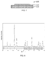
- Fig. 2 is an explanatory drawing illustrating a honeycomb structure 40 which is an example of the joined body 20 and which is a honeycomb structure according to an embodiment of the present invention.
- the honeycomb structure 40 is configured to apply a voltage to electrode terminals 45 to heat a honeycomb base 41.
- the honeycomb structure 40 includes the honeycomb base 41; highly electrically conductive porous portions 42 having higher electrical conductivity than that of the honeycomb base 41, each of the highly electrically conductive porous portions 42 corresponding to the first member 22 (or the second member 24); metal electrodes 44 joined to the highly electrically conductive porous portions 42, each of the metal electrodes 44 corresponding to the second member 24 (or the first member 22); and the electrode terminals 45 connected to the metal electrodes 44.
- the joining portion 30 is composed of an oxide layer containing more than 45% by volume of a perovskite-type oxide phase and joins the highly electrically conductive porous portions 42 and the metal electrodes 44.
- a difference in electrical conductivity between the honeycomb base 41 and the highly electrically conductive porous portions 42 may be attributed to a difference in metal content therebetween.
- the honeycomb structure is composed of a Si-bonded SiC ceramic
- the highly electrically conductive porous portions 42 may have a higher Si content.
- the method for producing a joined body according to this embodiment may include, for example, (A) a base formation step of forming a first member and a second member and (B) a joining step of forming a joining portion (composed of the foregoing oxide layer) between the first member and the second member to join the first member and the second member.
- the base formation step (A) may be omitted.
- the base is formed.
- the base may be formed by mixing raw materials together, molding the resulting mixture by a predetermined molding method, and firing the resulting molded article.
- the porous ceramic may be formed so as to contain one or more inorganic materials selected from, for example, carbides, such as silicon carbide, titanium carbide, zirconium carbide, and boron carbide, nitrides, such as silicon nitride, aluminum nitride, titanium nitride, and zirconium nitride, oxynitrides, such as SIALON, silicides, such as molybdenum silicide, and zirconium phosphate.
- the porous ceramic may be formed so as to contain one or more inorganic materials selected from, for example, cordierite, mullite, zeolite, aluminum titanate, aluminum oxide, zirconium oxide, titanium oxide, silicon oxide, and magnesium oxide.
- an inorganic material serving as an aggregate, a pore-forming material, and a dispersion medium are mixed to prepare a clay body or a slurry.
- a raw material composition is preferably adjusted in such a manner that the porosity and the average pore diameter of the porous ceramic are in the ranges described above, specifically, for example, the porous ceramic has a porosity of 10% by volume or more and an average pore diameter of 1 or more and 300 ⁇ m or less.
- a treatment for filling pores of the porous ceramic with an impregnating material by impregnation may be performed to form the first member and the second member.
- the impregnation treatment may be performed by, for example, forming an impregnating base on the porous ceramic and performing heating at a temperature at which the impregnating base is melted.
- the impregnating material may be metallic Si.
- each of the members may be processed into a predetermined form.
- the metal members are not particularly limited as long as they are composed of a metal, for example, a typical metal or a transition metal.
- a highly electrically conductive metal is preferred.
- transition metals a metal, for example, Fe, Co, Ni, or Cu, or an alloy thereof is preferred.
- a noble metal for example, Pt or Au, may be used, depending on the application.
- the metal members may be processed into, for example, a plate form.
- a difference in thermal expansion coefficient between the first member and the second member formed in this step may be 6 ppm/K or more. Even in the case of a joined body in which members having a relatively large difference in thermal expansion coefficient therebetween are joined together, a joining portion composed of an oxide ceramic permits the joining strength and the electrical conductivity to be maintained. In particular, also in the case of a joined body used under repeated heating, the joining strength and the electrical conductivity are maintained.
- a Si-bonded SiC ceramic composite material
- a plastic clay body may be formed by mixing a SiC powder and a Si powder together in a predetermined volume ratio, adding a dispersion medium, such as water, a pore-forming material, an organic binder, and so forth thereto, and kneading the mixture.
- a dispersion medium such as water, a pore-forming material, an organic binder, and so forth thereto, and kneading the mixture.
- a material to be burned off during firing is preferred.
- starch, coke, or a foaming resin may be used.
- the binder for example, an organic binder, such as a cellulose-based material, is preferably used.
- a surfactant such as ethylene glycol
- the porous ceramic may be formed into a honeycomb formed article having a freely-selected form as described above by extrusion molding with a mold including cells juxtaposed.
- the resulting honeycomb formed article is preferably subjected to drying treatment, calcination treatment, and firing treatment.
- the calcination treatment is a treatment in which an organic component contained in the honeycomb formed article is removed by combustion at a temperature lower than a firing temperature.
- the firing temperature may be 1400°C or higher and 1500°C or lower and preferably 1430°C or higher and 1450°C or lower.
- a firing atmosphere is not particularly limited. An inert atmosphere is preferred. An Ar atmosphere is more preferred.
- the honeycomb base (Si-bonded SiC ceramic) sintered body can be obtained through the step described above.
- the joining step may include, for example, (B-1) a laminate production substep of arranging a joining portion raw material between the first member and the second member to produce a laminate, and (B-2) a firing substep of firing the laminate.
- the laminate production substep (B-1) may be omitted.
- the joining portion raw material is arranged between the first member and the second member to produce the laminate.
- the joining portion raw material contains a raw material (oxide layer raw material) for an oxide layer containing more than 45% by volume of a perovskite-type oxide phase.
- the oxide layer raw material may contain a perovskite-type oxide itself, may contain one or more of a metal (an elemental metal or an alloy) containing a metal contained in the perovskite-type oxide and a compound containing a metal contained in the perovskite-type oxide, or may contain both of them. Of these, more preferably, a metal powder and a compound powder are contained.
- the synthesis of a perovskite-type oxide and the joining of the first member and the second member with the oxide layer containing the perovskite-type oxide can be simultaneously performed, thereby reducing the process cost.
- the compound powder preferably contains one or more selected from the group consisting of oxide powders, carbonate powders, hydroxide powders, and chloride powders.
- oxide powders carbonate powders, hydroxide powders, and chloride powders.
- the reason for this is that these compound powders react mildly with a metal powder, compared with nitrates and sulfates, thus resulting in good workability.
- a hydroxide powder and a carbonate powder are more preferred.
- Raw materials for these compound powders are stably available at low cost. These compound powders react with a metal powder more mildly, thus resulting in better workability.
- the compound powder is a powder of a compound containing a metal element contained in the oxide layer of the joined body described above.
- the compound powder may be composed of a simple metal compound containing a single type of metal element or may be composed of a composite metal compound containing two or more types of metal elements.
- the metal element contained in the compound powder may be any one of metal elements contained in the oxide layer of the joined body described above. Among those metal elements, a metal element contained in the perovskite-type oxide is preferred. A metal element occupying the A sites of the perovskite-type oxide is more preferred.
- the compound powder for example, La 2 O 3 , SrCO 3 , La(OH) 3 , CaCO 3 , CaCl 2 , Gd(OH) 3 , or GdCl 2 is preferred. La(OH) 3 or SrCO 3 is more preferred.
- a powder of the perovskite-type oxide contained in the oxide layer of the joined body described above may also be used. In this case, however, a step of synthesizing the perovskite-type oxide is needed, thus reducing the production efficiency.
- a powder of a metal oxide other than the perovskite-type oxide contained in the oxide layer of the joined body described above may be used.
- the compound powder preferably has an average particle diameter of, for example, 0.05 ⁇ m or more and 50 ⁇ m or less. In this range, an appropriate joining strength is easily obtained.
- the average particle diameter is preferably 0.1 ⁇ m or more and more preferably 0.5 ⁇ m or more.
- the average particle diameter is preferably 30 ⁇ m or less and more preferably 15 ⁇ m or less.
- the average particle diameter of a powder of the oxide layer raw material indicates a median diameter (D50) measured with a laser diffraction/scattering particle size distribution analyzer using water as a dispersion medium.
- the metal powder is a powder of a metal containing a metal element contained in the oxide layer of the joined body described above.
- the metal powder may be composed of a simple metal containing a single type of metal element or may be composed of an alloy containing two or more types of metal elements.
- the metal element contained in the metal powder may be any one of metal elements contained in the oxide layer of the joined body described above. Of these, the metal element contained in the metal powder is more preferably a metal element occupying the B sites of the perovskite-type oxide.
- the metal element for example, Cu, Fe, Ni, Mn, or Ti is preferred. Cu or Fe is more preferred.
- the metal powder preferably has an average particle diameter of, for example, 1 ⁇ m or more and 40 ⁇ m or less.
- An average particle diameter of 1 ⁇ m or more results in ease of handling because the reactivity is not too high.
- the average particle diameter is more preferably 3 ⁇ m or more.
- the average particle diameter is preferably 30 ⁇ m or less and more preferably 10 ⁇ m or less.
- Preferred examples of the oxide layer raw material include a material containing a compound powder composed of La(OH) 3 and a metal powder composed of Cu; a material containing a compound powder composed of SrCO 3 and a metal powder composed of Fe; a material containing a compound powder composed of La 2 O 3 and a metal powder composed of Ni; a material containing a compound powder composed of CaCO 3 and a metal powder composed of Fe; and a material containing a compound powder composed of La(OH) 3 and SrCl 2 and a metal powder composed of Mn.
- the material containing a compound powder composed of La(OH) 3 and a metal powder composed of Cu, and the material containing a compound powder composed of SrCO 3 and a metal powder composed of Fe are more preferred.
- a joined body including a joining portion that contains La 2 CuO 4 serving as a perovskite-type oxide can be produced.
- a joined body including a joining portion that contains SrFeO 3 serving as a perovskite-type oxide can be produced.
- the oxide layer raw material may contain more than 50% by mass and 95% by mass or less of the compound powder and preferably contains 60% by mass or more and more preferably 70% by mass or more of the compound powder.
- the oxide layer raw material preferably contains 80% by mass or less of the compound powder.
- the oxide layer raw material may contain 5% by mass or more and less than 50% by mass of the metal powder and preferably contains 15% by mass or more and more preferably 20% by mass or more of the metal powder.
- the oxide layer raw material preferably contains 50% by mass or less and more preferably 40% by mass or less of the metal powder.
- the joining portion raw material may contain, for example, a binder, a solvent, a dispersant, and a plasticizer, in addition to the oxide layer raw material, and may be formed into, for example, a slurry-, paste-, or clay-like material.
- a binder for example, polyvinyl butyral (PVB) may be preferably used.
- the solvent for example, terpineol may be preferably used.
- a method for arranging the joining portion raw material between the first member and the second member to produce the laminate is not particularly limited.
- the laminate may be formed by applying a slurry or paste containing the oxide layer raw material powder to one or both of the first member and the second member by an application method and then laminating the first member and the second member so as to sandwich a surface to which the slurry or paste has been applied.
- high adhesion of the first member and the second member to the joining portion is provided.
- peeling at the joining portion is inhibited.
- the laminate may be formed by forming a molded article using, for example, an extrusion molding method with a clay-like material containing the oxide layer raw material powder and arranging the molded article between the first member and the second member.
- the laminate may be formed by arranging the oxide layer raw material powder alone between the first member and the second member and limiting the movement of the oxide layer raw material powder with a frame or the like.
- the laminate is fired.
- the perovskite-type oxide is sintered to form the perovskite-type oxide phase.
- the oxide layer raw material contains one or more of a metal and a compound thereof, the metal containing a metal contained in the perovskite-type oxide, they are oxidized alone or in combination to form the perovskite-type oxide phase.
- the firing atmosphere may be an oxidizing atmosphere, for example, atmospheric air or an oxygen atmosphere, or an inert atmosphere, for example, a nitrogen atmosphere or an argon atmosphere.
- the firing temperature may be set in a suitable range, depending on the materials of the first member, the second member, and the joining portion.
- the firing temperature may be 400°C or higher and 1200°C or lower.
- the perovskite-type oxide is more reliably synthesized.
- 1200°C or lower for example, changes in the properties of the first member and the second member during firing can be further inhibited.
- the firing temperature is preferably 500°C or higher, more preferably 600°C or higher, and still more preferably 700°C or higher.
- the upper limit of the firing temperature is preferably 1200°C or lower when the firing atmosphere is an inert atmosphere.
- the upper limit of the firing temperature is preferably 900°C or lower when the firing atmosphere is an oxidizing atmosphere.
- the firing time is preferably 0.1 hours or more and more preferably 0.5 hours or more.
- the firing time is preferably 24 hours or less, more preferably 10 hours or less, and still more preferably 2 hours or less.
- the joining portion contains more than 45% by volume of the perovskite-type oxide phase that increases the electrical conductivity.
- the oxide layer contained in the joining portion is composed of the oxide ceramic; hence, even if the joining portion is exposed to high temperature in air or the like, changes in material quality and characteristics are less likely to occur.
- the joining portion has electrical conductivity; hence, for example, when the first member and the second member each having electrical conductivity are used, the first member and the second member can be joined together in such a manner that a current can pass therethrough.
- Fig. 3 is an explanatory drawing illustrating a schematic structure of a covered body 120 serving as a composite body according to an embodiment of the present invention.
- the covered body 120 includes a base 122 and a covering portion 130 that covers a surface of the base 122.
- the base 122 may be composed of a porous material or dense material.
- the foregoing members exemplified as the first member 22 and the second member 24 may be used.
- the covering portion 130 is an oxide layer containing more than 45% by volume of a perovskite-type oxide phase and covers the whole or part of a surface of the base 122.
- the perovskite-type oxide seemingly contributes to the electrical conductivity to increase the electrical conductivity.
- the covering portion 130 may be the same as the joining portion 30, except that the covering portion 130 covers the surface of the base 122 in place of the joining of the first member 22 and the second member 24.
- the covering portion 130 may penetrate into pores of the porous material.
- the covering portion 130 having a structure that penetrates into the pores of the porous material is preferred because the adhesion strength between the base 122 and the covering portion 130 is further enhanced.
- the adhesion strength between the base 122 and the covering portion 130 is preferably 1.5 MPa or more.
- the adhesion strength is measured by a tensile test (complying with JIS R 1606).
- the adhesion strength is more preferably 3.0 MPa or more and still more preferably 5.0 MPa or more. Higher adhesion strength results in firmer adhesion to increase the reliability and thus is preferred.
- the covered body according to this embodiment is not particularly limited as long as it has a structure in which a surface of the base is covered with the covering portion.
- the covered body may be used for, for example, honeycomb structures, thermoelectric elements, ceramic heaters, gas sensors for the detection of oxygen, NOx, and other gases, and fuel cells.
- the covered body may be preferably used to heat the honeycomb structure by the application of a voltage to electrodes.
- Fig. 4 is an explanatory drawing illustrating a honeycomb structure 140 which is an example of the covered body 120 and which is a honeycomb structure according to an embodiment of the present invention.
- the honeycomb structure 140 includes a honeycomb base 142 corresponding to the base 122 and electrode portions 150 each corresponding to the covering portion 130 and is configured to apply a voltage to the electrode portions 150 to heat the honeycomb base 142.
- a voltage may be applied to the electrode portions 150 through, for example, electrode terminals (not illustrated).
- Each of the electrode portions 150 is formed of the oxide layer containing more than 45% by volume of the perovskite-type oxide phase.
- the method for producing a covered body according to this embodiment may include, for example, (A) a base formation step of forming a base and (B) a covering step of forming a covering portion (the oxide layer described above) on the base to cover the base.
- the base formation step (A) may be omitted.
- the base is formed.
- This base formation step may be the same step as that of the base formation step according to the foregoing first embodiment.
- a covering treatment for covering the base with the covering portion is performed.
- the covering step may include, for example, (B-1) a laminate production substep of arranging a covering portion raw material on the whole or part of a surface of the base to produce a laminate, and (B-2) a firing substep of firing the laminate.
- the laminate production substep (B-1) may be omitted.
- the covering portion raw material is arranged on the surface of the base to produce the laminate.
- the covering portion raw material contains a raw material for an oxide layer containing more than 45% by volume of a perovskite-type oxide phase (oxide layer raw material).
- the covering portion raw material may be the same as the joining portion raw material described in the laminate production substep according to the first embodiment.
- a method for arranging the covering portion raw material on the surface of the base to produce the laminate is not particularly limited.
- the laminate may be formed by applying a slurry or paste containing the oxide layer raw material powder to the surface of the base by an application method. In this case, high adhesion of the base and the covering portion is provided. Thus, for example, peeling of the covering portion is inhibited.
- the laminate may be formed by forming a molded article using, for example, an extrusion molding method with a clay-like material containing the oxide layer raw material powder and arranging the molded article on the surface of the base.
- the laminate may be formed by arranging the oxide layer raw material powder alone on the surface of the base and limiting the movement of the oxide layer raw material powder with a frame or the like.
- the laminate is fired in an oxidizing atmosphere.
- firing conditions such as the firing temperature, the firing time, and the firing atmosphere, are set in a suitable range, depending on the material of the covering portion.
- the firing conditions may be set as those described in the first embodiment.
- the covering portion contains more than 45% by volume of the perovskite-type oxide phase that increases the electrical conductivity.
- the oxide layer contained in the covering portion is composed of an oxide ceramic; hence, even if the covering portion is exposed to high temperature in air or the like, changes in material quality and characteristics are less likely to occur.
- the covering portion has electrical conductivity; hence, for example, when the base having electrical conductivity is used, the base enables a current to pass therethrough with the covering portion.
- a joined body 20B may be provided, the joined body 20B including a first member 22B, a second member 24B joined to part of the first member 22B, and a joining portion 30B joining the first member 22B and the second member 24B.
- the joined body 20B is a composite body including both of the joined body with the joining portion and the covered body with the covering portion.
- Fig. 6 is an explanatory drawing illustrating a honeycomb structure 240 which is an example of the composite body and which is a honeycomb structure according to an embodiment of the present invention.
- the honeycomb structure 240 has the same structure as that of the honeycomb structure 140 illustrated in Fig.
- honeycomb structure 240 includes electrode terminals 245 and that the honeycomb base 142 is joined to the electrode terminals 245 with parts (joining portions) of the electrode portions 150.
- the area of the second member may be larger, smaller, or equal to that of the joining portion, and is preferably smaller than that of the joining portion.
- the covered body in which the covering portion is arranged on the whole of the surface of the base has been mainly described.
- the covering portion may be arranged on part of the surface of the base.
- a covered body 120B may be provided, the covered body 120B including a base 122B and a covering portion 130B arranged on part of a surface of the base.
- the composite body in which the oxide layer is arranged on a surface of the base has been mainly described.
- a composite body in which oxide layers are arranged on a plurality of surfaces of a base may be provided.
- a composite body in which oxide layers are arranged on all surfaces of a base may be provided.
- honeycomb structures 40, 140, and 240 have been described.
- a honeycomb structure of the present invention is not limited to these structures and may include the foregoing composite body (joined body or covered body).
- a honeycomb structure in which a honeycomb base having a honeycomb structure is provided as a base and in which electrode portions formed of oxide layers are provided on the honeycomb base is preferred.
- the electrode portions including predetermined oxide layers are present; hence, the occurrence of the nonuniform distribution of heat generated is inhibited to uniformly perform heating, thereby leading to good durability.
- EHC electrical heating catalyst carrier
- the perovskite-type oxide of the electrode portions is a material stable at a high temperature of 1000°C or higher in air, exhibits only a small change in resistance, and inhibits the occurrence of the locally nonuniform distribution of heat generated.
- oxidation may proceed from about 400°C to cause a change in resistance, thereby leading to the occurrence of the locally nonuniform distribution of heat generated.
- Experimental examples 1 to 9 correspond to the examples of the present invention.
- Experimental example 10 and 11 correspond to a comparative example. It should be appreciated that the present invention is not limited to the following examples and can be implemented in numerous ways without departing from the technical scope of the present invention.
- a member composed of Si-bonded SiC (porous ceramic) was arranged thereon to form a laminate.
- the laminate was dried in air at 80°C for 4 hours while being pressed with an alumina plate arranged on the Si-bonded SiC member.
- the dry laminate was fired in air at 750°C for an hour to produce a joined body of Experimental example 1.
- a joined body of Experimental example 2 was produced as in Experimental example 1, except that the firing temperature was changed to 800°C.
- a joined body of Experimental example 3 was produced as in Experimental example 1, except that the firing atmosphere was changed to Ar and that the firing temperature was changed to 1000°C.
- a joined body of Experimental example 4 was produced as in Experimental example 2, except that the oxide layer raw material powder was changed to a La 2 CuO 4 powder and that the firing atmosphere was changed to Ar.
- a joined body of Experimental example 5 was produced as in Experimental example 4, except that the firing temperature was changed to 900°C.
- the La 2 CuO 4 powder used in Experimental examples 4 and 5 was synthesized as described below. La 2 O 3 and CuO were weighed in such a manner that a desired composition was obtained.
- a joined body of Experimental example 8 was produced as in Experimental example 1, except that an Fe powder (27.4% by mass) and a SrCO 3 powder (72.6% by mass) were mixed together to prepare an oxide layer raw material powder.
- a joined body of Experimental example 9 was produced as in Experimental example 8, except that the oxide layer raw material powder was changed to a SrFeO 3 powder, the firing atmosphere was changed to Ar, and the firing temperature was changed to 900°C.
- the SrFeO 3 powder used in Experimental example 9 was synthesized as described below.
- Fe 2 O 3 and SrCO 3 were weighed in such a manner that a desired composition was obtained.
- Mixing was performed for 4 hours by ball milling with IPA serving as a solvent and iron-core nylon balls serving as grinding media to prepare a slurry.
- the slurry was dried in a nitrogen atmosphere at 110°C for 14 hours to prepare a mixed powder.
- the mixed powder was calcined in air at 1200°C and then subjected to ball milling for 16 hours with IPA serving as a solvent and ZrO 2 balls serving as grinding media.
- the resulting slurry was dried in the same way as described above to prepare the SrFeO 3 powder.
- a joined body of Experimental example 10 was produced as in Experimental example 1, except that an Fe powder (98.9% by mass) and a TiO 2 powder (1.1% by mass) were mixed together to prepare an oxide layer raw material powder.
- a joined body of Experimental example 11 was produced as in Experimental example 2, except that an Fe powder (69.3% by mass) and ZnO (30.7% by mass) were mixed to prepare an oxide layer raw material powder.
- FIG. 10 illustrates an X-ray diffraction pattern of Experimental example 10.
- the resulting X-ray diffraction data was analyzed using "X-ray data analysis software JADE 7" manufactured by MDI.
- the proportion of the crystal phase was determined by a reference intensity ratio (RIR) method with "X-ray data analysis software JADE 7" manufactured by MDI.
- RIR reference intensity ratio
- each of the joined bodies was evaluated by SEM observation of a cross section of each joined body.
- the joined body produced as described above was embedded in a resin and polished to a nearly specular surface with, for example, a diamond slurry, thereby producing an observation sample.
- the sample is then observed with a SEM at a magnification of X1500 or more to check the delamination between the joining portion and each of the porous ceramic and the metal member and the occurrence of cracking in the porous ceramic, the metal member, and the joining portion.
- the evaluation was performed according to the following criteria. The case where none of the delamination or the occurrence of the cracking were observed was rated as "A (excellent)". The case where significant delamination or cracking was observed was rated as "F (failure)".
- the joining strength of each of the joined bodies was evaluated by a tensile test (complying with JIS R1606).
- the case where the joining strength was 5.0 MPa or more was rated as "A (excellent)".
- the case where the joining strength was 3.0 MPa or more and less than 5.0 MPa was rated as "B (good)”.
- the case where the joining strength was 1.5 MPa or more and less than 3.0 MPa was rated as "C (fair)”.
- the case where the joining strength was less than 1.5 MPa was rated as "F (failure)”.
- the electrical conductivity of the joining portion was evaluated as described below.
- the stainless-steel (SUS) member and the Si-bonded SiC member each having a hole with a diameter of 2 mm were used.
- the stainless-steel (SUS) member and the Si-bonded SiC member were joined together in such a manner that the holes were alternately arranged (the holes were not superimposed) (see Figs. 11A to 11C ).
- a Ag paste (4922N, manufactured by du Pont) was applied to the joining portion (oxide layer) exposed through the hole having a diameter of 2 mm of the SUS member and the joining portion exposed through the hole having a diameter of 2 mm of the Si-bonded SiC member.
- the resulting green electrodes were dried to form electrodes for the measurement of electrical conductivity. Needle-like terminals were pressed against the resulting measurement electrodes. An electrical resistance was measured by a direct-current two-terminal method.
- the evaluation of the electrical conductivity was performed before and after a heat resistance test. The heat resistance test was performed as described below. A current was allowed to pass through the electrode terminals of each measurement sample to heat the joined body to 800°C, and the sample was maintained at the temperature for 24 hours.
- Tables 1, 2, and 3 lists the proportions of the raw materials fed, the firing atmosphere, the firing temperature, the joinability, the joining strength, and the electrical conductivity of the joining portion (before and after the heat resistance test) of the joined bodies of Experimental examples 1 to 7, Experimental examples 8 and 9, and Experimental examples 10 and 11.
- each of the joining portions had a low electrical conductivity of 0.4 S/cm or less before the heat resistance test and 0.05 S/cm or less after the heat resistance test.
- each of the joining portions had a high electrical conductivity of at least 0.1 S/cm or more after the heat resistance test.
- a decrease in electrical conductivity due to the heat resistance test was small. The reason for this is presumably as follows: For example, as is clear from equilibrium diagrams illustrated in Figs.
- the oxide layer raw material In Experimental examples 1 to 3 and 6 to 8, in which the raw materials for synthesis were used, the joining strength was high, compared with Experimental examples 4, 5, and 9, in which the synthesized perovskite-type oxides were used.
- the joined bodies were produced at low temperatures, compared with the cases where the synthesized perovskite-type oxide was used.
- the firing temperature For example, in the case where Cu and La(OH) 3 were used as the oxide layer raw materials, the oxidation of Cu and the decomposition of La(OH) 3 proceeded more smoothly at 700°C or higher. An unnecessary reaction did not occur at 1200°C or lower, thus providing the good oxide layer. It was found that in the case where firing was performed in air, firing at 900°C or higher allowed stainless steel (SUS) to oxidize; hence, the firing temperature was more preferably 900°C or lower.
- SUS stainless steel
- the firing temperature was preferably 900°C or higher and 1200°C or lower.
- Fe and SrCO 3 were used as the oxide layer raw materials, when firing was performed in air, the oxidation of Fe and the decomposition of SrCO 3 proceeded more smoothly at 700°C or higher. An unnecessary reaction did not occur at 1200°C or lower, thus providing the good oxide layer.
- the firing temperature was more preferably 900°C or lower. It was found that in the case where firing was performed in the Ar atmosphere (low-oxygen atmosphere), the oxidation of stainless steel (SUS) was further inhibited, and the oxidation of Fe could proceed in trace amounts of oxygen; hence, the firing temperature was preferably 900°C or higher and 1200°C or lower.
- the perovskite-type oxide phase resulted in higher electrical conductivity and that the perovskite-type oxide phase was preferably contained in a proportion of, for example, 70% by mass (67.7% by volume) or more, more preferably 75% by mass (72.9% by volume) or more, still more preferably 80% by mass (78.2% by volume) or more, and yet even more preferably 90% by mass (89.0% by volume) or more.
- the perovskite-type oxide phase was contained in a proportion of 45% by volume (47.7% by mass) or more, the electrical conductivity was presumed to be increased.
- the joining portion is required to have, for example, characteristics as described below. (1) The joining portion has good joinability to both of the first member and the second member. (2) The joining portion does not react with the first member or the second member. Even if the joining portion reacts with the first member or the second member, no reaction phase that significantly reduces the joinability or the electrical conductivity is formed. (3) The joining portion has high electrical conductivity. (4) The joining portion is stable in air at room temperature to about 1000°C. (5) The joining portion has a thermal expansion coefficient close to those of both of the first member and the second member.
- La 2 CuO 4 used in Experimental examples 1 to 7 satisfies all requirements (1) to (5) described above.
- One reason for good joinability is presumably as follows: At an interface with Si-bonded SiC, Si diffuses continuously in the joining portion. At an interface with stainless steel (SUS), a component in SUS430 (for example, Mn) diffuses continuously in the joining portion.
- SUS430 for example, Mn
- SrFeO 3 used in Experimental examples 8 and 9 satisfies requirements (1) to (4). Although SrFeO 3 had a large thermal expansion coefficient, SrFeO 3 had good joinability when used for the joining portion. One reason for this is presumably as follows: In the case where Fe and SrFeO 3 were used as starting raw materials, a good balance was achieved between the volume expansion due to oxidation and reaction and contraction behavior associated with densification. Another reason for good joinability is presumably as follows: As with the case of La 2 CuO 4 , components diffuse continuously in the joining portion at both interfaces. A good affinity between the materials that do not form a reaction phase results in better joinability.
- the present invention is applicable to, for example, the field of the production of a composite body in which an oxide layer is arranged on a base, for example, a porous ceramic or a metal member.
Landscapes
- Chemical & Material Sciences (AREA)
- Engineering & Computer Science (AREA)
- Ceramic Engineering (AREA)
- Materials Engineering (AREA)
- Structural Engineering (AREA)
- Organic Chemistry (AREA)
- Manufacturing & Machinery (AREA)
- Composite Materials (AREA)
- Mechanical Engineering (AREA)
- Ceramic Products (AREA)
- Laminated Bodies (AREA)
Abstract
Description
- This application claim the benefit of priority from Japanese patent application No.
JP-2015-057672 (filed on 20 March 2015 - The present invention relates to a composite body, honeycomb structure, and a method for producing the composite body.
- Hitherto, composite bodies including oxide layers with electrical conductivity, for example, joined bodies including joining portions composed of oxide layers with electrical conductivity and covered bodies including a covering portion composed of oxide layers with electrical conductivity, have been desired. As a joining material used for the production of a joined body, for example, a conductive joining material containing a nickel oxide powder, a nickel metal powder, an iron oxide powder, and a vehicle has been reported (see Patent Literature 1). In Patent Literature 1, members are bonded with the conductive joining material and treated at 1000°C or higher to join the members together. As a covering material for the production of a covered body, for example, a covering material containing a metal, for example, copper or aluminum, and a covering material containing a composite material composed of MoSi2 and at least one of Si and SiC have been reported (Patent Literatures 2 and 3).
- As ceramics with electrical conductivity, perovskite-type oxides have been known. As a method for producing a perovskite-type oxide, for example, it is reported that combustion synthesis is performed with a reaction raw material containing a powder of a metal in group 4, a carbonate of an element of group 2, and a sodium perchlorate, and then reaction products are pulverized and washed with water (see Patent Literature 4). In Patent Literature 4, the combustion synthesis is performed under conditions including an adiabatic flame temperature of 1500°C or higher. The reaction products are a synthesized powder and a by-product (NaCl). By pulverizing the reaction product and then washing the pulverized product with water, the by-product is sufficiently removed. Thus, the perovskite-type ceramic having a nearly theoretical density is obtained by sintering.
-
- PTL 1: Japanese Patent No.
3891790 - PTL 2: Japanese Unexamined Patent Application Publication No.
2011-099405 - PTL 3: Japanese Unexamined Patent Application Publication No.
2014-062476 - PTL 4: Japanese Patent No.
4874574 - In the case where a joined body is produced with a joining material disclosed in Patent Literature 1, however, the electrical conductivity is not good, in some cases. A covered body including a covering portion (oxide layer) in place of the covering portions disclosed in
Patent Literatures 2 and 3 has been desired. In the case where a composite body is produced by the method for producing a perovskite-type oxide disclosed in Patent Literature 4, the electrical conductivity is not good, in some cases. It has thus been desired to provide a novel composite body having better electrical conductivity. - The present invention has been accomplished in order to overcome the foregoing problems. It is a main object of the present invention to provide a novel composite body having better electrical conductivity and a method for producing the composite body.
- To achieve the foregoing main object, the inventors have conducted intensive studies, have conceived that, for example, a raw material containing a La(OH)3 powder and a Cu powder is arranged and fired on a base (for example, a portion between target members to be joined together or on a surface of a target member to be covered), and have found that in this case, a composite body having better electrical conductivity is produced. The findings have led to the completion of the present invention.
- A composite body of the present invention includes:
- a base, and
- an oxide layer arranged on the base, the oxide layer containing more than 45% by volume of a perovskite-type oxide phase.
- A honeycomb structure of the present invention includes the composite body described above.
- A method according to the present invention for producing a composite body, the method includes a step of:
- firing a laminate including an oxide layer raw material arranged on a base to form an oxide layer on the base, the oxide layer containing more than 45% by volume of a perovskite-type oxide phase.
- According to the composite body of the present invention and the method for producing the composite body, it is possible to provide a novel composite body having better electrical conductivity. The reason for this is presumably that, for example, the oxide layer contains more than 45% by volume of the perovskite-type oxide phase; hence, the electrical conductivity is increased.
-
-
Fig. 1 is an explanatory drawing of an example of a schematic structure of a joinedbody 20. -
Fig. 2 is an explanatory drawing illustrating ahoneycomb structure 40 which is an example of the joinedbody 20. -
Fig. 3 is an explanatory drawing illustrating a schematic structure of a coveredbody 120. -
Fig. 4 is an explanatory drawing illustrating ahoneycomb structure 140 which is an example of the coveredbody 120. -
Fig. 5 is an explanatory drawing illustrating a schematic structure of a joinedbody 20B. -
Fig. 6 is an explanatory drawing illustrating a honeycomb structure 240 which is an example of the joinedbody 20. -
Fig. 7 is an explanatory drawing illustrating a schematic structure of a coveredbody 120B. -
Fig. 8 illustrates an X-ray diffraction pattern of Experimental example 1. -
Fig. 9 illustrates an X-ray diffraction pattern of Experimental example 9. -
Fig. 10 illustrates an X-ray diffraction pattern of Experimental example 10. -
Figs 11A to 11C illustrate a joined body used in the measurement of electrical conductivity. -
Fig. 12 is an equilibrium diagram of La2CuO4. -
Fig. 13 is an equilibrium diagram of Fe2O3-SrO. -
Fig. 14 is an equilibrium diagram of Fe2O3-TiO2. -
Fig. 15 is an equilibrium diagram of Fe2O3-ZnO. - A composite body of the present invention includes a base and an oxide layer arranged on the base, the oxide layer containing more than 45% by volume of a perovskite-type oxide phase. For example, the composite body may be a joined body including a first member, a second member, and a joining portion that joins the first member and the second member, at least one of the first member and the second member serving as the base described above, and the joining portion serving as the oxide layer. For example, the composite body may be a covered body including the base described above and a covering portion that covers the whole or part of a surface of the base, the covering portion serving as the oxide layer described above. Embodiments of the present invention will be described below with reference to the drawings.
-
Fig. 1 is an explanatory drawing of an example of a schematic structure of a joinedbody 20 serving as a composite body according to an embodiment of the present invention. As illustrated inFig. 1 , the joinedbody 20 includes a first member 22, asecond member 24, and a joiningportion 30 that joins the first member 22 and thesecond member 24. Each of the first member 22 and thesecond member 24 may be composed of a porous material or a dense material. The joinedbody 20 may be a body in which a porous material and a porous material are joined together, a body in which a porous material and a dense material are joined together, or a body in which a dense material and a dense material are joined together. The first member 22 and thesecond member 24 may be composed of the same or different materials. - Each of the first member 22 and the
second member 24 that are targets to be joined together may be composed of a porous ceramic. The porous ceramic is not particularly limited as long as it is a ceramic with a porous structure. The porous structure may have open pores on its surfaces. For example, the porous structure may have a porosity of 10% by volume or more, preferably 20% by volume or more, and more preferably 40% by volume or more. In view of simple production, the porosity is preferably 90% by volume or less. The porosity of the porous ceramic may be appropriately selected, depending on, for example, the application. The porous ceramic preferably has an average pore diameter of, for example, 1 µm or more and 300 µm or less. In this range, the oxide layer contained in the joining portion penetrates easily into the pores in the porous ceramic, thereby resulting in firmer joining. The average pore diameter is preferably 5 µm or more and more preferably 10 µm or more. The average pore diameter is preferably 100 µm or less and more preferably 50 µm or less. The porosity and the average pore diameter of the porous ceramic indicate the results obtained from mercury intrusion porosimetry measurement. - The porous ceramic may be formed so as to contain one or more inorganic materials selected from, for example, carbides, such as silicon carbide, titanium carbide, zirconium carbide, and boron carbide, nitrides; nitrides, such as silicon nitride, aluminum nitride, titanium nitride, and zirconium nitride; oxynitrides, such as SIALON; silicides, such as molybdenum silicide; and zirconium phosphate. The porous ceramic may also be formed so as to contain one or more inorganic materials selected from, for example, cordierite, mullite, zeolite, aluminum titanate, aluminum oxide, zirconium oxide, titanium oxide, silicon oxide, and magnesium oxide. The form of the porous ceramic is not particularly limited and may be selected, depending on the application. Examples of the form include plate forms, cylindrical forms, and honeycomb forms. A form having a structure through which fluid passes may also be used. Specifically, the porous ceramic preferably has a honeycomb structure including a partition portion configured to form a plurality of cells serving as passages of fluid. The porous ceramic may have electrical conductivity. In this case, the porous ceramic is preferably composed of a composite material containing SiC and Si, SiC being bonded with Si, pores being defined by SiC and Si. The Si-bonded SiC ceramic has electrical conductivity. For example, a metal member serving as an electrode can be joined thereto. In such a case, the application of the present invention has significance. The porous ceramic may be composed of a composite material (Si3N4-bonded SiC) containing SiC and Si3N4, SiC being bonded with Si3N4, pores being defined by SiC and Si3N4.
- Each of the first member 22 and the
second member 24 that are targets to be joined together may be composed of a dense material. The dense material is not particularly limited as long as it is dense and has low porosity. For example, each of the first member 22 and thesecond member 24 may be a metal member or may be composed of a dense ceramic. The dense material may have a porosity of, for example, 5% by volume or less, preferably 1% by volume or less, and more preferably 0.5% by volume or less. The metal member is not particularly limited as long as it is composed of a metal, such as a typical metal or a transition metal. For example, a metal member having high electrical conductivity is preferred. Among transition metals, a metal, for example, Fe, Co, Ni, or Cu, or an alloy thereof is preferred. A noble metal, for example, Pt or Au, may be used, depending on the application. The metal member may serve as an electrode. In this case, stainless steel, for example, a Cr-Ni-Fe-based alloy (e.g., SUS304, SUS309, or SUS310) or a Cr-Fe-based alloy (e.g., SUS430), is preferably used. The metal member is preferably composed of an alloy containing at least Fe and Cr and more preferably an alloy at least containing 70% by mass or more and less than 90% by mass Fe and 10% by mass or more and less than 30% by mass Cr. This is because the material is stable and has good electrical conductivity. The metal member may be composed of, for example, a heat resistant alloy. The heat resistant alloy may be an Fe-based heat resistant alloy, for example, a Ni-Co-Fe-based alloy (e.g., Kovar) or a Ni-Fe-based alloy (e.g., Invar), or a Ni-based heat resistant alloy, for example, Inconel (Ni-Cr-based alloy) or Hastelloy (Ni-Fe-Mo-based alloy). The metal member may be composed of a Mn-containing material, for example, SUS304, 309, 310, SUS430, Kovar, or Hastelloy. In this case, Mn is presumed to diffuse continuously in the joining portion to enhance the joinability. The form of the metal member, for example, a plate form, may be appropriately selected, depending on the application. Examples of the dense ceramic include a ceramic obtained by densely sintering any of the foregoing materials exemplified for the porous ceramic; a member produced by filling pores in porous ceramic with, for example, a filler or an impregnating material; and a composite oxide member containing a plurality of metals. A specific example of the filled member is a Si-impregnated SiC sintered body in which pores of porous SiC are filled with metallic Si by impregnation. This material has good thermal conductivity and good electrical conductivity owing to metallic Si. As the composite oxide member, an electrically conductive ceramic material, for example, a LaCrO3-based material, a BaTiO3-based material, a LaMnO3-based material, a LaCoO3-based material, a NaCo2O4-based material, a Ca3CO4O9-based material, a LaNiO3-based material, or a SrTiO2-based material may be used. The term "-based material" is used to indicate that the material includes, for example, a material partially substituted with an alkali metal element, an alkaline-earth metal, or an element different in valence. Specifically, the LaMnO3-based material includes, for example, (La0.9Sr0.1)MnO3. These materials may be used as materials for fuel cells (for example, SOFC), thermoelectric elements, sensors, and the like. - Among the foregoing materials, each of the first member 22 and the
second member 24 that are targets to be joined together is preferably composed of at least one of the Si-containing ceramics and the Fe-containing alloys. These materials have better joinability to the joiningportion 30 containing a perovskite-type oxide phase. As the Si-containing ceramics, for example, SiC, Si-impregnated SiC, Si3N4, and Si3N4-bonded SiC are preferred. As the Fe-containing alloys, for example, iron-based alloys, such as stainless steel (SUS), Kovar, and Invar, Inconel, and Hastelloy are preferred. In addition to the Fe-containing alloys, alloys containing, for example, Co, Ni, and Cu, which are transition metals the same as Fe, which are similar in electron configuration to that of Fe, and which have ionic radii close to that of Fe, are also presumed to have good joinability to the joiningportion 30 containing a perovskite-type oxide phase. - In the first member 22 and the
second member 24, which are targets to be joined together, a difference in thermal expansion coefficient therebetween may be 4.0 ppm/K or more, 5.0 ppm/K or more, or 6.0 ppm/K or more. Even in the case of a joined body in which members having a relatively large difference in thermal expansion coefficient therebetween are joined together, a joining portion composed of an oxide ceramic permits the joining strength and the electrical conductivity to be maintained. In particular, also in the case of a joined body used under repeated heating, the joining strength and the electrical conductivity are maintained. For example, a Cr-Ni-Fe-based alloy (SUS304) has a thermal expansion coefficient of 18 ppm/K. A Cr-Fe-based alloy (SUS430) has a thermal expansion coefficient of 12 ppm/K. A Si-bonded SiC sintered body has a thermal expansion coefficient of 4.5 ppm/K. LaCrO3 has a thermal expansion coefficient of 9.4 ppm/K. - The joining
portion 30 is an oxide layer containing more than 45% by volume of a perovskite-type oxide phase and joins the first member 22 and thesecond member 24. In the joiningportion 30, a perovskite-type oxide seemingly contributes to the electrical conductivity to increase the electrical conductivity. - The term "perovskite-type oxide" is a general term that includes an oxide having a perovskite structure represented by the general formula ABO3; and oxides each having a perovskite-related structure in which a perovskite structure and another structure are mixed together. An example of the oxide having a perovskite-related structure is an oxide having a layered perovskite structure. The oxide having a layered perovskite structure may be an oxide having a layered structure which is represented by, for example, the general formula A2BO4 and in which ABO3 layers each having a perovskite structure and AO layers each having a rock salt structure are alternately stacked in the c-axis direction. In the general formulae ABO3 and A2BO4, the A sites may be occupied by one or more selected from the group consisting of alkali metals, alkaline-earth metals, and rare-earth metals. In these oxides, a perovskite structure or a perovskite-related structure is easily formed. Specifically, the A sites each may be occupied by, for example, a monovalent cation, e.g., Li, Na, K, or Ag, a divalent cation, e.g., Pb, Ba, Sr, or Ca, or a trivalent cation, e.g., Bi, La, Ce, or Nd. The B sites may be occupied by one or more selected from transition metals. In these oxides, a perovskite structure or a perovskite-related structure is easily formed. Specifically, the B sites each may be occupied by, for example, a monovalent cation, e.g., Li or Cu, a divalent cation, e.g., Mg, Ni, Zn, Co, Sn, Fe, Cd, Cu, or Cr, a trivalent cation, e.g., Mn, Sb, Al, Yb, In, Fe, Co, Sc, Y, or Sn, a tetravalent cation, e.g. Ti or Zr, a pentavalent cation, e.g., Nb, Sb, Ta, or Bi, or a hexavalent cation, e.g., W, Te, or Re. The term "general formula" is used to indicate that a compound represented by each general formula may be stoichiometric or that at least one element in a compound represented by each general formula may be contained in an excessive or deficient amount or may be partially substituted with another element. For example, in an oxide having a perovskite structure, oxygen deficiency is more likely to occur because of, for example, the influence of a synthetic atmosphere; hence, an oxide represented by ABO3-x (0 < × < 3) may be regarded as a perovskite-type oxide.
- As the perovskite-type oxide, for example, La2CuO4, SrFeO3, La2NiO4, LaCuO3, LaFeO3, CaFeO3, GdFeO3, SrTiO3, LaNiO3, or (La,Sr)MnO3 is preferred. At least one of an oxide containing La and Cu and an oxide containing Sr and Fe is more preferred. At least one of La2CuO4 and SrFeO3 is still more preferred. The reason for this is that these oxides have good electrical conductivity to lead to the joining portion having higher electrical conductivity.
- The joining
portion 30 may be composed of a single-phase perovskite-type oxide or a composite phase including, for example, a perovskite-type oxide phase and a metal oxide phase other than a perovskite-type oxide phase. The perovskite-type oxide phase may contain a single kind of perovskite-type oxide or two or more kinds of perovskite-type oxide. The term "single-phase perovskite-type oxide" is used to indicate that a perovskite-type oxide phase may be contained in an amount of 100% by volume and that an oxide phase other than the perovskite-type oxide phase may be contained in an amount of 5% by volume or less, 3% by volume or less, or 1% by volume or less. - The metal oxide contained in the composite phase may be a metal oxide different from the foregoing perovskite-type oxide and may be a simple metal oxide containing a single type of metal or a composite metal oxide containing two or more types of metals. The metal oxide may contain a transition metal. The metal oxide preferably contains one or more selected from Fe, Co, Ni, Mn, Cu, Ti, V, Zr, Nb, Mo, Ta, and W and more preferably contains, for example, Fe, Ni, Mn, and/or Cu. For example, the metal oxide may be one or more of Fe2O3, NiO, MnO2, and CuO. The metal oxide may have electrical conductivity or may not have electrical conductivity.
- The metal oxide contained in the composite phase preferably contains the same metal element as that contained in the perovskite-type oxide and is more preferably a simple metal oxide containing the same metal element as that occupying the B sites of the perovskite-type oxide. Preferred examples of the composite phase include a composite phase containing La2CuO4 serving as a perovskite-type oxide and CuO serving as a metal oxide; a composite phase containing SrFeO3 serving as a perovskite-type oxide and Fe2O3 serving as a metal oxide; a composite phase containing La2NiO4 serving as a perovskite-type oxide and NiO serving as a metal oxide; a composite phase containing SrTiO3 serving as a perovskite-type oxide and TiO2 serving as a metal oxide; and a composite phase containing (La,Sr)MnO3 serving as a perovskite-type oxide and MnO2 serving as a metal oxide. Of these, the composite phase containing La2CuO4 serving as a perovskite-type oxide and CuO serving as a metal oxide and the composite phase containing SrFeO3 serving as a perovskite-type oxide and Fe2O3 serving as a metal oxide are more preferred. These composite phases result in better electrical conductivity and joinability.
- The joining
portion 30 may contain more than 45% by volume of the perovskite-type oxide phase, preferably contains 70% by volume or more, more preferably 90% by volume or more, and still more preferably 97% by volume or more of the perovskite-type oxide phase. In the case where the perovskite-type oxide is contained in an amount more than 45% by volume, the electrical conductivity is increased. The joiningportion 30 may contain less than 55% by volume of the metal oxide, preferably contains 30% by volume or less, more preferably 10% by volume or less, and still more preferably 3% by volume or less of the metal oxide. In the case where the metal oxide is contained, the joinability of the base and the oxide layer is enhanced. In the case where the metal oxide is contained in an amount less than 55% by volume, the amount of the perovskite-type oxide is not too small, thus inhibiting a decrease in electrical conductivity. - The joining
portion 30 preferably has a porosity of 90% by volume or less, more preferably 50% by volume or less, and still more preferably 30% by volume or less. The joiningportion 30 is more preferably composed of a dense material in view of the electrical conductivity and the joining strength. The joiningportion 30 preferably has a porosity of 5% by volume or more, more preferably 10% by volume or more, and still more preferably 20% by volume or more. The joiningportion 30 more preferably has pores in view of stress relaxation. A method for calculating the porosity of the joining portion will be described. A microstructure image captured with a SEM is subjected to image analysis using image analysis software to determine the porosity of the joining portion. A portion having an area of 0.5 × 10⁻⁶ m2 of the joining portion is randomly selected and binarized to distinguish between images of pores and the oxide layer. Conditions of the binarization are appropriately set, depending on the resulting image. For example, values obtained empirically are used. In the binarized image, the pores and the oxide layer are separated, and the area ratio thereof is calculated to determine the porosity. The area ratio in a cross section is assumed to be almost equivalent to the volume ratio, and thus the porosity (% by volume) is obtained. - In the case where at least one of the first member 22 and the
second member 24 is composed of a porous material, the joiningportion 30 may penetrate into pores of the porous material. The joiningportion 30 having a structure that penetrates into the pores of the porous material is preferred because the joining strength is further increased. - The joining
portion 30 preferably has an electrical conductivity of 0.1 S/cm or more, more preferably 1 S/cm or more, and still more preferably 10 S/cm or more. The joining portion having higher electrical conductivity has superior electrical conductivity, thus leading to efficient use of electricity. The upper limit of the electrical conductivity will be about 1.0 × 10⁵ S/cm in consideration of the material composition. The electrical conductivity is measured by a two-terminal method using a measurement sample in which electrodes are baked on the joiningportion 30 of the joinedbody 20. - In the joined
body 20, the joining strength between the first member 22 and thesecond member 24 is preferably 1.5 MPa or more. The joining strength is measured by a tensile test (complying with JIS R 1606). The joining strength is more preferably 3.0 MPa or more and still more preferably 5.0 MPa or more. Higher joining strength results in firmer joining to increase the reliability and thus is preferred. The adhesion strength between the first member 22 and the joiningportion 30 and the adhesion strength between thesecond member 24 and the joiningportion 30 are presumed to be at least equal to or higher than the joining strength between the first member 22 and thesecond member 24. - The joined body according to this embodiment is not particularly limited as long as it has a structure in which the first member and the second member are joined together. For example, the joined body may be used for, for example, honeycomb structures, thermoelectric elements, ceramic heaters, gas sensors for the detection of oxygen, NOx, and other gases, and fuel cells. For example, in the case of a honeycomb structure, the joined body may be preferably used to heat the honeycomb structure by the application of a voltage to the metal member.
Fig. 2 is an explanatory drawing illustrating ahoneycomb structure 40 which is an example of the joinedbody 20 and which is a honeycomb structure according to an embodiment of the present invention. Thehoneycomb structure 40 is configured to apply a voltage toelectrode terminals 45 to heat ahoneycomb base 41. Thehoneycomb structure 40 includes thehoneycomb base 41; highly electrically conductiveporous portions 42 having higher electrical conductivity than that of thehoneycomb base 41, each of the highly electrically conductiveporous portions 42 corresponding to the first member 22 (or the second member 24);metal electrodes 44 joined to the highly electrically conductiveporous portions 42, each of themetal electrodes 44 corresponding to the second member 24 (or the first member 22); and theelectrode terminals 45 connected to themetal electrodes 44. As with the joinedbody 20 illustrated inFig. 1 , the joiningportion 30 is composed of an oxide layer containing more than 45% by volume of a perovskite-type oxide phase and joins the highly electrically conductiveporous portions 42 and themetal electrodes 44. A difference in electrical conductivity between thehoneycomb base 41 and the highly electrically conductiveporous portions 42 may be attributed to a difference in metal content therebetween. For example, in the case where the honeycomb structure is composed of a Si-bonded SiC ceramic, the highly electrically conductiveporous portions 42 may have a higher Si content. - A method for producing a joined body according to this embodiment will be described below. The method for producing a joined body according to this embodiment may include, for example, (A) a base formation step of forming a first member and a second member and (B) a joining step of forming a joining portion (composed of the foregoing oxide layer) between the first member and the second member to join the first member and the second member. In the case where the first member and the second member are separately prepared, the base formation step (A) may be omitted.
- In this step, the base is formed. For example, in the case where the first member and the second member are composed of a porous ceramic or a dense ceramic, the base may be formed by mixing raw materials together, molding the resulting mixture by a predetermined molding method, and firing the resulting molded article. The porous ceramic may be formed so as to contain one or more inorganic materials selected from, for example, carbides, such as silicon carbide, titanium carbide, zirconium carbide, and boron carbide, nitrides, such as silicon nitride, aluminum nitride, titanium nitride, and zirconium nitride, oxynitrides, such as SIALON, silicides, such as molybdenum silicide, and zirconium phosphate. The porous ceramic may be formed so as to contain one or more inorganic materials selected from, for example, cordierite, mullite, zeolite, aluminum titanate, aluminum oxide, zirconium oxide, titanium oxide, silicon oxide, and magnesium oxide. In this step, for example, an inorganic material serving as an aggregate, a pore-forming material, and a dispersion medium are mixed to prepare a clay body or a slurry. In this case, a raw material composition is preferably adjusted in such a manner that the porosity and the average pore diameter of the porous ceramic are in the ranges described above, specifically, for example, the porous ceramic has a porosity of 10% by volume or more and an average pore diameter of 1 or more and 300 µm or less. In this step, a treatment for filling pores of the porous ceramic with an impregnating material by impregnation may be performed to form the first member and the second member. The impregnation treatment may be performed by, for example, forming an impregnating base on the porous ceramic and performing heating at a temperature at which the impregnating base is melted. In the case where the porous ceramic is formed of a Si-bonded SiC sintered body, the impregnating material may be metallic Si.
- In this step, in the case where the first member and the second member are metallic members, each of the members may be processed into a predetermined form. The metal members are not particularly limited as long as they are composed of a metal, for example, a typical metal or a transition metal. For example, a highly electrically conductive metal is preferred. Among transition metals, a metal, for example, Fe, Co, Ni, or Cu, or an alloy thereof is preferred. A noble metal, for example, Pt or Au, may be used, depending on the application. The metal members may be processed into, for example, a plate form.
- A difference in thermal expansion coefficient between the first member and the second member formed in this step may be 6 ppm/K or more. Even in the case of a joined body in which members having a relatively large difference in thermal expansion coefficient therebetween are joined together, a joining portion composed of an oxide ceramic permits the joining strength and the electrical conductivity to be maintained. In particular, also in the case of a joined body used under repeated heating, the joining strength and the electrical conductivity are maintained.
- Regarding the base formation step, for example, the case where a Si-bonded SiC ceramic (composite material) is formed as the porous ceramic will be specifically described. In this case, for example, a plastic clay body may be formed by mixing a SiC powder and a Si powder together in a predetermined volume ratio, adding a dispersion medium, such as water, a pore-forming material, an organic binder, and so forth thereto, and kneading the mixture. As the pore-forming material, a material to be burned off during firing is preferred. For example, starch, coke, or a foaming resin may be used. As the binder, for example, an organic binder, such as a cellulose-based material, is preferably used. As a dispersant, a surfactant, such as ethylene glycol, may be used. For example, the porous ceramic may be formed into a honeycomb formed article having a freely-selected form as described above by extrusion molding with a mold including cells juxtaposed. The resulting honeycomb formed article is preferably subjected to drying treatment, calcination treatment, and firing treatment. The calcination treatment is a treatment in which an organic component contained in the honeycomb formed article is removed by combustion at a temperature lower than a firing temperature. The firing temperature may be 1400°C or higher and 1500°C or lower and preferably 1430°C or higher and 1450°C or lower. A firing atmosphere is not particularly limited. An inert atmosphere is preferred. An Ar atmosphere is more preferred. The honeycomb base (Si-bonded SiC ceramic) sintered body can be obtained through the step described above.
- In this step, a joining treatment for joining the first member and the second member with the joining portion is performed. The first member and the second member may be freely selected from the foregoing members. The joining step may include, for example, (B-1) a laminate production substep of arranging a joining portion raw material between the first member and the second member to produce a laminate, and (B-2) a firing substep of firing the laminate. In the case where the laminate including the joining portion raw material arranged between the first member and the second member is separately prepared, the laminate production substep (B-1) may be omitted.
- In this substep, the joining portion raw material is arranged between the first member and the second member to produce the laminate. The joining portion raw material contains a raw material (oxide layer raw material) for an oxide layer containing more than 45% by volume of a perovskite-type oxide phase. The oxide layer raw material may contain a perovskite-type oxide itself, may contain one or more of a metal (an elemental metal or an alloy) containing a metal contained in the perovskite-type oxide and a compound containing a metal contained in the perovskite-type oxide, or may contain both of them. Of these, more preferably, a metal powder and a compound powder are contained. In the following firing substep, the synthesis of a perovskite-type oxide and the joining of the first member and the second member with the oxide layer containing the perovskite-type oxide can be simultaneously performed, thereby reducing the process cost.
- The compound powder preferably contains one or more selected from the group consisting of oxide powders, carbonate powders, hydroxide powders, and chloride powders. The reason for this is that these compound powders react mildly with a metal powder, compared with nitrates and sulfates, thus resulting in good workability. Among those described above, a hydroxide powder and a carbonate powder are more preferred. The reason for this is as follow: Raw materials for these compound powders are stably available at low cost. These compound powders react with a metal powder more mildly, thus resulting in better workability. The compound powder is a powder of a compound containing a metal element contained in the oxide layer of the joined body described above. The compound powder may be composed of a simple metal compound containing a single type of metal element or may be composed of a composite metal compound containing two or more types of metal elements. The metal element contained in the compound powder may be any one of metal elements contained in the oxide layer of the joined body described above. Among those metal elements, a metal element contained in the perovskite-type oxide is preferred. A metal element occupying the A sites of the perovskite-type oxide is more preferred. As the compound powder, for example, La2O3, SrCO3, La(OH)3, CaCO3, CaCl2, Gd(OH)3, or GdCl2 is preferred. La(OH)3 or SrCO3 is more preferred. As the compound powder, a powder of the perovskite-type oxide contained in the oxide layer of the joined body described above may also be used. In this case, however, a step of synthesizing the perovskite-type oxide is needed, thus reducing the production efficiency. As the compound powder, a powder of a metal oxide other than the perovskite-type oxide contained in the oxide layer of the joined body described above may be used. The compound powder preferably has an average particle diameter of, for example, 0.05 µm or more and 50 µm or less. In this range, an appropriate joining strength is easily obtained. The average particle diameter is preferably 0.1 µm or more and more preferably 0.5 µm or more. Furthermore, the average particle diameter is preferably 30 µm or less and more preferably 15 µm or less. The average particle diameter of a powder of the oxide layer raw material indicates a median diameter (D50) measured with a laser diffraction/scattering particle size distribution analyzer using water as a dispersion medium.
- The metal powder is a powder of a metal containing a metal element contained in the oxide layer of the joined body described above. The metal powder may be composed of a simple metal containing a single type of metal element or may be composed of an alloy containing two or more types of metal elements. The metal element contained in the metal powder may be any one of metal elements contained in the oxide layer of the joined body described above. Of these, the metal element contained in the metal powder is more preferably a metal element occupying the B sites of the perovskite-type oxide. As the metal element, for example, Cu, Fe, Ni, Mn, or Ti is preferred. Cu or Fe is more preferred. The metal powder preferably has an average particle diameter of, for example, 1 µm or more and 40 µm or less. In this range, an appropriate joining strength is easily obtained. An average particle diameter of 1 µm or more results in ease of handling because the reactivity is not too high. The average particle diameter is more preferably 3 µm or more. The average particle diameter is preferably 30 µm or less and more preferably 10 µm or less.
- Preferred examples of the oxide layer raw material include a material containing a compound powder composed of La(OH)3 and a metal powder composed of Cu; a material containing a compound powder composed of SrCO3 and a metal powder composed of Fe; a material containing a compound powder composed of La2O3 and a metal powder composed of Ni; a material containing a compound powder composed of CaCO3 and a metal powder composed of Fe; and a material containing a compound powder composed of La(OH)3 and SrCl2 and a metal powder composed of Mn. Of these, the material containing a compound powder composed of La(OH)3 and a metal powder composed of Cu, and the material containing a compound powder composed of SrCO3 and a metal powder composed of Fe are more preferred. In the case where an oxide layer raw material powder containing La(OH)3 and Cu is used, a joined body including a joining portion that contains La2CuO4 serving as a perovskite-type oxide can be produced. In the case where an oxide layer raw material powder containing SrCO3 and Fe is used, a joined body including a joining portion that contains SrFeO3 serving as a perovskite-type oxide can be produced.
- The oxide layer raw material may contain more than 50% by mass and 95% by mass or less of the compound powder and preferably contains 60% by mass or more and more preferably 70% by mass or more of the compound powder. The oxide layer raw material preferably contains 80% by mass or less of the compound powder. The oxide layer raw material may contain 5% by mass or more and less than 50% by mass of the metal powder and preferably contains 15% by mass or more and more preferably 20% by mass or more of the metal powder. The oxide layer raw material preferably contains 50% by mass or less and more preferably 40% by mass or less of the metal powder.
- The joining portion raw material may contain, for example, a binder, a solvent, a dispersant, and a plasticizer, in addition to the oxide layer raw material, and may be formed into, for example, a slurry-, paste-, or clay-like material. As the binder, for example, polyvinyl butyral (PVB) may be preferably used. As the solvent, for example, terpineol may be preferably used.
- A method for arranging the joining portion raw material between the first member and the second member to produce the laminate is not particularly limited. For example, the laminate may be formed by applying a slurry or paste containing the oxide layer raw material powder to one or both of the first member and the second member by an application method and then laminating the first member and the second member so as to sandwich a surface to which the slurry or paste has been applied. In this case, high adhesion of the first member and the second member to the joining portion is provided. Thus, for example, peeling at the joining portion is inhibited. The laminate may be formed by forming a molded article using, for example, an extrusion molding method with a clay-like material containing the oxide layer raw material powder and arranging the molded article between the first member and the second member. The laminate may be formed by arranging the oxide layer raw material powder alone between the first member and the second member and limiting the movement of the oxide layer raw material powder with a frame or the like.
- In this substep, the laminate is fired. In this substep, in the case where the oxide layer raw material contains the perovskite-type oxide, the perovskite-type oxide is sintered to form the perovskite-type oxide phase. In the case where the oxide layer raw material contains one or more of a metal and a compound thereof, the metal containing a metal contained in the perovskite-type oxide, they are oxidized alone or in combination to form the perovskite-type oxide phase.
- In this substep, the firing atmosphere may be an oxidizing atmosphere, for example, atmospheric air or an oxygen atmosphere, or an inert atmosphere, for example, a nitrogen atmosphere or an argon atmosphere. In this substep, the firing temperature may be set in a suitable range, depending on the materials of the first member, the second member, and the joining portion. The firing temperature may be 400°C or higher and 1200°C or lower. At 400°C or higher, the perovskite-type oxide is more reliably synthesized. At 1200°C or lower, for example, changes in the properties of the first member and the second member during firing can be further inhibited. The firing temperature is preferably 500°C or higher, more preferably 600°C or higher, and still more preferably 700°C or higher. The upper limit of the firing temperature is preferably 1200°C or lower when the firing atmosphere is an inert atmosphere. The upper limit of the firing temperature is preferably 900°C or lower when the firing atmosphere is an oxidizing atmosphere. The firing time is preferably 0.1 hours or more and more preferably 0.5 hours or more. The firing time is preferably 24 hours or less, more preferably 10 hours or less, and still more preferably 2 hours or less.
- In the joined body of this embodiment and the method for producing the joined body described above, it is possible to provide a novel joined body with good electrical conductivity because the joining portion contains more than 45% by volume of the perovskite-type oxide phase that increases the electrical conductivity. In addition, for example, the oxide layer contained in the joining portion is composed of the oxide ceramic; hence, even if the joining portion is exposed to high temperature in air or the like, changes in material quality and characteristics are less likely to occur. Furthermore, for example, the joining portion has electrical conductivity; hence, for example, when the first member and the second member each having electrical conductivity are used, the first member and the second member can be joined together in such a manner that a current can pass therethrough.
-
Fig. 3 is an explanatory drawing illustrating a schematic structure of a coveredbody 120 serving as a composite body according to an embodiment of the present invention. As illustrated inFig. 3 , the coveredbody 120 includes abase 122 and a coveringportion 130 that covers a surface of thebase 122. The base 122 may be composed of a porous material or dense material. As the base 122 that is a target covered, for example, the foregoing members exemplified as the first member 22 and thesecond member 24 may be used. - The covering
portion 130 is an oxide layer containing more than 45% by volume of a perovskite-type oxide phase and covers the whole or part of a surface of thebase 122. In the coveringportion 130, the perovskite-type oxide seemingly contributes to the electrical conductivity to increase the electrical conductivity. The coveringportion 130 may be the same as the joiningportion 30, except that the coveringportion 130 covers the surface of the base 122 in place of the joining of the first member 22 and thesecond member 24. In the case where thebase 122 is composed of a porous material, the coveringportion 130 may penetrate into pores of the porous material. The coveringportion 130 having a structure that penetrates into the pores of the porous material is preferred because the adhesion strength between the base 122 and the coveringportion 130 is further enhanced. - In the covered
body 120, the adhesion strength between the base 122 and the coveringportion 130 is preferably 1.5 MPa or more. The adhesion strength is measured by a tensile test (complying with JIS R 1606). The adhesion strength is more preferably 3.0 MPa or more and still more preferably 5.0 MPa or more. Higher adhesion strength results in firmer adhesion to increase the reliability and thus is preferred. - The covered body according to this embodiment is not particularly limited as long as it has a structure in which a surface of the base is covered with the covering portion. For example, the covered body may be used for, for example, honeycomb structures, thermoelectric elements, ceramic heaters, gas sensors for the detection of oxygen, NOx, and other gases, and fuel cells. For example, in the case of a honeycomb structure, the covered body may be preferably used to heat the honeycomb structure by the application of a voltage to electrodes.
Fig. 4 is an explanatory drawing illustrating ahoneycomb structure 140 which is an example of the coveredbody 120 and which is a honeycomb structure according to an embodiment of the present invention. Thehoneycomb structure 140 includes ahoneycomb base 142 corresponding to thebase 122 andelectrode portions 150 each corresponding to the coveringportion 130 and is configured to apply a voltage to theelectrode portions 150 to heat thehoneycomb base 142. A voltage may be applied to theelectrode portions 150 through, for example, electrode terminals (not illustrated). Each of theelectrode portions 150 is formed of the oxide layer containing more than 45% by volume of the perovskite-type oxide phase. - A method for producing a covered body according to this embodiment will be described below. The method for producing a covered body according to this embodiment may include, for example, (A) a base formation step of forming a base and (B) a covering step of forming a covering portion (the oxide layer described above) on the base to cover the base. In the case where the base is separately prepared, the base formation step (A) may be omitted.
- In this step, the base is formed. This base formation step may be the same step as that of the base formation step according to the foregoing first embodiment.
- In this step, a covering treatment for covering the base with the covering portion is performed. As the base, any one of the foregoing members may be used. The covering step may include, for example, (B-1) a laminate production substep of arranging a covering portion raw material on the whole or part of a surface of the base to produce a laminate, and (B-2) a firing substep of firing the laminate. In the case where the laminate including the covering portion raw material arranged on the surface of the base is separately prepared, the laminate production substep (B-1) may be omitted.
- In this substep, the covering portion raw material is arranged on the surface of the base to produce the laminate. The covering portion raw material contains a raw material for an oxide layer containing more than 45% by volume of a perovskite-type oxide phase (oxide layer raw material). The covering portion raw material may be the same as the joining portion raw material described in the laminate production substep according to the first embodiment.
- A method for arranging the covering portion raw material on the surface of the base to produce the laminate is not particularly limited. For example, the laminate may be formed by applying a slurry or paste containing the oxide layer raw material powder to the surface of the base by an application method. In this case, high adhesion of the base and the covering portion is provided. Thus, for example, peeling of the covering portion is inhibited. The laminate may be formed by forming a molded article using, for example, an extrusion molding method with a clay-like material containing the oxide layer raw material powder and arranging the molded article on the surface of the base.
- The laminate may be formed by arranging the oxide layer raw material powder alone on the surface of the base and limiting the movement of the oxide layer raw material powder with a frame or the like.
- In this substep, the laminate is fired in an oxidizing atmosphere. In this firing substep, firing conditions, such as the firing temperature, the firing time, and the firing atmosphere, are set in a suitable range, depending on the material of the covering portion. For example, the firing conditions may be set as those described in the first embodiment.
- In the covered body of this embodiment and the method for producing the covered body described above, it is possible to provide a novel covered body with good electrical conductivity because the covering portion contains more than 45% by volume of the perovskite-type oxide phase that increases the electrical conductivity. In addition, for example, the oxide layer contained in the covering portion is composed of an oxide ceramic; hence, even if the covering portion is exposed to high temperature in air or the like, changes in material quality and characteristics are less likely to occur. Furthermore, for example, the covering portion has electrical conductivity; hence, for example, when the base having electrical conductivity is used, the base enables a current to pass therethrough with the covering portion.
- The present invention is not limited to the foregoing embodiments. It should be appreciated that the present invention can be implemented in various ways without departing from the technical scope of the present invention.
- For example, in
Figs. 1 and 2 , the joined body in which the first member and the joining portion are not exposed has been mainly described. Part of the first member may be exposed. Part of the second member may be exposed. Part of the joining portion (at least one of part of a surface of the joining portion adjacent to the first member and part of a surface of the joining portion adjacent to the second member) may be exposed. Two or more of these parts may be exposed. For example, as illustrated inFig. 5 , a joinedbody 20B may be provided, the joinedbody 20B including afirst member 22B, asecond member 24B joined to part of thefirst member 22B, and a joiningportion 30B joining thefirst member 22B and thesecond member 24B. In the joinedbody 20B, part of a surface of thefirst member 22B adjacent to the joiningportion 30B is exposed. Part of a surface of the joiningportion 30B adjacent to thesecond member 24B is exposed. In this case, a portion of the joiningportion 30B whose surface is exposed corresponds to the covering portion in the second embodiment. In other words, the joinedbody 20B is a composite body including both of the joined body with the joining portion and the covered body with the covering portion.Fig. 6 is an explanatory drawing illustrating a honeycomb structure 240 which is an example of the composite body and which is a honeycomb structure according to an embodiment of the present invention. The honeycomb structure 240 has the same structure as that of thehoneycomb structure 140 illustrated inFig. 4 , except that the honeycomb structure 240 includeselectrode terminals 245 and that thehoneycomb base 142 is joined to theelectrode terminals 245 with parts (joining portions) of theelectrode portions 150. The area of the second member may be larger, smaller, or equal to that of the joining portion, and is preferably smaller than that of the joining portion. - For example, in
Fig. 3 , the covered body in which the covering portion is arranged on the whole of the surface of the base has been mainly described. The covering portion may be arranged on part of the surface of the base. For example, as illustrated inFig. 7 , a coveredbody 120B may be provided, the coveredbody 120B including a base 122B and a coveringportion 130B arranged on part of a surface of the base. - For example, in the embodiment described above, the composite body in which the oxide layer is arranged on a surface of the base has been mainly described. A composite body in which oxide layers are arranged on a plurality of surfaces of a base may be provided. A composite body in which oxide layers are arranged on all surfaces of a base may be provided.
- For example, in the foregoing embodiments, the
honeycomb structures honeycomb structure 140 or 240) is preferred. In the case where such a honeycomb structure is used as, for example, an electrical heating catalyst carrier (EHC) in which a current passes through electrode portions, the electrode portions including predetermined oxide layers are present; hence, the occurrence of the nonuniform distribution of heat generated is inhibited to uniformly perform heating, thereby leading to good durability. The reason for this is presumably that the perovskite-type oxide of the electrode portions is a material stable at a high temperature of 1000°C or higher in air, exhibits only a small change in resistance, and inhibits the occurrence of the locally nonuniform distribution of heat generated. As described inPatent Literatures 3 and 4, in the case where a metal or MoSi2 is used for electrode portions, oxidation may proceed from about 400°C to cause a change in resistance, thereby leading to the occurrence of the locally nonuniform distribution of heat generated. - Examples of the specific production of a composite body (joined body) of the present invention will be described below as experimental examples. Experimental examples 1 to 9 correspond to the examples of the present invention. Experimental example 10 and 11 correspond to a comparative example. It should be appreciated that the present invention is not limited to the following examples and can be implemented in numerous ways without departing from the technical scope of the present invention.
- In Experimental examples 1 to 5, joined bodies each including an oxide layer containing a La2CuO4 phase serving as a perovskite-type oxide phase were produced. Specifically, a Cu powder (14.3% by mass) and a La(OH)3 powder (85.7% by mass) were mixed together to prepare an oxide layer raw material powder. Then, α-terpineol serving as a solvent and polyvinyl butyral (PVB) serving as a binder were added thereto. These materials were mixed together to prepare a paste. The resulting paste was defoamed with a planetary centrifugal mixer and then applied to a member (metal member) composed of stainless steel (SUS) (Cr-Fe-based alloy, SUS430) by printing. A member composed of Si-bonded SiC (porous ceramic) was arranged thereon to form a laminate. The laminate was dried in air at 80°C for 4 hours while being pressed with an alumina plate arranged on the Si-bonded SiC member. The dry laminate was fired in air at 750°C for an hour to produce a joined body of Experimental example 1.
- A joined body of Experimental example 2 was produced as in Experimental example 1, except that the firing temperature was changed to 800°C. A joined body of Experimental example 3 was produced as in Experimental example 1, except that the firing atmosphere was changed to Ar and that the firing temperature was changed to 1000°C. A joined body of Experimental example 4 was produced as in Experimental example 2, except that the oxide layer raw material powder was changed to a La2CuO4 powder and that the firing atmosphere was changed to Ar. A joined body of Experimental example 5 was produced as in Experimental example 4, except that the firing temperature was changed to 900°C. The La2CuO4 powder used in Experimental examples 4 and 5 was synthesized as described below. La2O3 and CuO were weighed in such a manner that a desired composition was obtained. Mixing was performed for 4 hours by ball milling with IPA serving as a solvent and iron-core nylon balls serving as grinding media to prepare a slurry. The slurry was dried in a nitrogen atmosphere at 110°C for 14 hours to prepare a mixed powder. The mixed powder was calcined in air at 1000°C and then subjected to ball milling for 16 hours with IPA serving as a solvent and ZrO2 balls serving as grinding media. The resulting slurry was dried in the same way as described above to prepare the La2CuO4 poweder.
- In Experimental examples 6 and 7, joined bodies including oxide layers containing a La2CuO4 phase in different proportions were produced. Specifically, a joined body of Experimental example 6 was produced as in Experimental example 1, except that proportions of the Cu powder and the La(OH)3 powder were 22.7% by mass and 77.3% by mass, respectively. A joined body of Experimental example 7 was produced as in Experimental example 1, except that proportions of the Cu powder and the La(OH)3 powder were 36.6% by mass and 63.4% by mass, respectively.
- In Experimental examples 8 and 9, joined bodies each including an oxide layer containing a SrFeO3 phase serving as a perovskite-type oxide phase were produced. Specifically, a joined body of Experimental example 8 was produced as in Experimental example 1, except that an Fe powder (27.4% by mass) and a SrCO3 powder (72.6% by mass) were mixed together to prepare an oxide layer raw material powder. A joined body of Experimental example 9 was produced as in Experimental example 8, except that the oxide layer raw material powder was changed to a SrFeO3 powder, the firing atmosphere was changed to Ar, and the firing temperature was changed to 900°C. The SrFeO3 powder used in Experimental example 9 was synthesized as described below. Fe2O3 and SrCO3 were weighed in such a manner that a desired composition was obtained. Mixing was performed for 4 hours by ball milling with IPA serving as a solvent and iron-core nylon balls serving as grinding media to prepare a slurry. The slurry was dried in a nitrogen atmosphere at 110°C for 14 hours to prepare a mixed powder. The mixed powder was calcined in air at 1200°C and then subjected to ball milling for 16 hours with IPA serving as a solvent and ZrO2 balls serving as grinding media. The resulting slurry was dried in the same way as described above to prepare the SrFeO3 powder.
- In Experimental examples 10 and 11, joined bodies each including an oxide layer that did not contain a perovskite-type oxide phase were produced. Specifically, a joined body of Experimental example 10 was produced as in Experimental example 1, except that an Fe powder (98.9% by mass) and a TiO2 powder (1.1% by mass) were mixed together to prepare an oxide layer raw material powder. A joined body of Experimental example 11 was produced as in Experimental example 2, except that an Fe powder (69.3% by mass) and ZnO (30.7% by mass) were mixed to prepare an oxide layer raw material powder.
- The crystal phase of the joining portion of each of the joined bodies produced as described above was identified. The measurement was performed with a rotating anode X-ray diffractometer (RINT, manufactured by Rigaku Corporation). The metal member was removed from the joined body produced as described above to expose the joining portion. The resulting article was used as a measurement sample. An X-ray diffraction pattern of a surface of the joining portion was obtained. Conditions of the X-ray diffraction measurement were as follows: CuKα radiation source, 50 kV, 300 mA, and 2θ = 20° to 60°.
Fig. 8 illustrates an X-ray diffraction pattern of Experimental example 1.Fig. 9 illustrates an X-ray diffraction pattern of Experimental example 9.Fig. 10 illustrates an X-ray diffraction pattern of Experimental example 10. The resulting X-ray diffraction data was analyzed using "X-ray data analysis software JADE 7" manufactured by MDI. The results demonstrated that each of the joining portions of Experimental examples 1 to 9 was composed of a perovskite-type oxide phase, whereas each of the joining portions of Experimental examples 10 and 11 was not composed of a perovskite-type oxide phase. The proportion of the crystal phase was determined by a reference intensity ratio (RIR) method with "X-ray data analysis software JADE 7" manufactured by MDI. - The joinability of each of the joined bodies was evaluated by SEM observation of a cross section of each joined body. The joined body produced as described above was embedded in a resin and polished to a nearly specular surface with, for example, a diamond slurry, thereby producing an observation sample. The sample is then observed with a SEM at a magnification of X1500 or more to check the delamination between the joining portion and each of the porous ceramic and the metal member and the occurrence of cracking in the porous ceramic, the metal member, and the joining portion. The evaluation was performed according to the following criteria. The case where none of the delamination or the occurrence of the cracking were observed was rated as "A (excellent)". The case where significant delamination or cracking was observed was rated as "F (failure)".
- The joining strength of each of the joined bodies was evaluated by a tensile test (complying with JIS R1606). The case where the joining strength was 5.0 MPa or more was rated as "A (excellent)". The case where the joining strength was 3.0 MPa or more and less than 5.0 MPa was rated as "B (good)". The case where the joining strength was 1.5 MPa or more and less than 3.0 MPa was rated as "C (fair)". The case where the joining strength was less than 1.5 MPa was rated as "F (failure)".
- The electrical conductivity of the joining portion was evaluated as described below. In the production of each of the joined bodies of Experimental examples 1 to 11, the stainless-steel (SUS) member and the Si-bonded SiC member each having a hole with a diameter of 2 mm were used. The stainless-steel (SUS) member and the Si-bonded SiC member were joined together in such a manner that the holes were alternately arranged (the holes were not superimposed) (see
Figs. 11A to 11C ). A Ag paste (4922N, manufactured by du Pont) was applied to the joining portion (oxide layer) exposed through the hole having a diameter of 2 mm of the SUS member and the joining portion exposed through the hole having a diameter of 2 mm of the Si-bonded SiC member. The resulting green electrodes were dried to form electrodes for the measurement of electrical conductivity. Needle-like terminals were pressed against the resulting measurement electrodes. An electrical resistance was measured by a direct-current two-terminal method. The volume resistivity r (Ωcm) was calculated from the expression r = R × S/L where R represents a measured electrical resistance (Ω), S represents the area of the measurement electrode (cm2), and L represents an interelectrode distance (cm). The electrical conductivity p (Scm-1) of electrode portions was calculated from the expression p = 1/R. The evaluation of the electrical conductivity was performed before and after a heat resistance test. The heat resistance test was performed as described below. A current was allowed to pass through the electrode terminals of each measurement sample to heat the joined body to 800°C, and the sample was maintained at the temperature for 24 hours. - Tables 1, 2, and 3 lists the proportions of the raw materials fed, the firing atmosphere, the firing temperature, the joinability, the joining strength, and the electrical conductivity of the joining portion (before and after the heat resistance test) of the joined bodies of Experimental examples 1 to 7, Experimental examples 8 and 9, and Experimental examples 10 and 11. In Experimental examples 10 and 11, in which the joining portions free from a perovskite-type oxide phase were provided, each of the joining portions had a low electrical conductivity of 0.4 S/cm or less before the heat resistance test and 0.05 S/cm or less after the heat resistance test. In contrast, in Experimental examples 1 to 9, in which the joining portions each containing the perovskite-type oxide phase were provided, each of the joining portions had a high electrical conductivity of at least 0.1 S/cm or more after the heat resistance test. The results demonstrated that the composite bodies each including the joining portion containing the perovskite-type oxide phase had higher electrical conductivity. In the composite bodies each including the joining portion containing the perovskite-type oxide phase, a decrease in electrical conductivity due to the heat resistance test was small. The reason for this is presumably as follows: For example, as is clear from equilibrium diagrams illustrated in
Figs. 12 to 15 , in the perovskite-type oxide, a stable equilibrium phase itself has electrical conductivity, so that the electrical conductivity does not change with a change in temperature. In contrast, in the case of each of the materials of Experimental examples 10 and 11, in which the electrical conductivity was imparted by dissolving a different element to form solid solutions, a solid-solution range (composition range where materials can form a solid solution) changes with temperature, so that the electrical conductivity changes with a change in temperature. - [Table 1]
Proportion of Raw Material (mass%) Firing Atmosphere Firing Temperature (°C) Proportion of Crystal Phase of Joining Portion (%) 1) Joinability 2) Joining Strength The Electrical Conductivity of Joining Portion (S/cm) Cu La(OH)3 La2CuO4 La2CuO4 CuO Before Heat Resistance Test After Heat Resistance Test Experimental Examples 1 14.3 85.7 0 Air 750 100 0 A A 16 17 Experimental Examples 2 Air 800 100 0 A A 16 16 Experimental Examples 3 Ar 1000 100 0 A A 16 16 Experimental Examples 4 0.0 0.0 100 Ar 800 100 0 A B 16 17 Experimental Examples 5 Ar 900 100 0 A B 16 16 Experimental Examples 6 22.7 77.3 0 Air 800 91 9 A A 3.2 3.0 Experimental Examples 7 36.6 63.4 0 Air 800 73 27 A A 0.1 0.1 1) A: excellent, F: failure
2) A: 5.0MPa or more, B: 3.0MPa or more and less than 5.0MPa, C: 1.5MPa or more and less than 3.0MPa, F: less than 1.5MPa[Table 2] Proportion of Raw Material (mass%) Firing Atmosphere Firing Temperature (°C) 1) Joinability 2) Joining Strength The Electrical Conductivity of Joining Portion (S/cm) Fe SrCO3 SrFeO3 Before Heat Resistance Test After Heat Resistance Test Experimental Example 8 27.4 72.6 0 Air 750 A A 10 3.3 Experimental Example 9 0 0 100.0 Ar 900 A B 10 3.5 1) A: excellent, F: failure
2) A: 5.0MPa or more, B: 3.0MPa or more and less than 5.0MPa, C: 1.5MPa or more and less than 3.0MPa, F: less than 1.5MPa[Table 3] Proportion of Raw Material (mass%) Firing Atmosphere Firing Temperature (°C) 1) Joinability 2) Joining Strength The Electrical Conductivity of Joining Portion (S/cm) Fe TiO2 ZnO Before Heat Resistance Test After Heat Resistance Test Experimental Example 10 98.9 1.1 0 Air 750 A A 0.3 0.08 Experimental Example 11 69.3 0 30.7 Air 800 A A 0.4 0.01 1) A: excellent, F: failure
2) A: 5.0MPa or more, B: 3.0MPa or more and less than 5.0MPa, C: 1.5MPa or more and less than 3.0MPa, F: less than 1.5MPa - Let us discuss the perovskite-type oxide phase. In Experimental examples 1 to 5, in which the perovskite-type oxide phase was the La2CuO4 phase, each of the joining portions had high electrical conductivity and a decrease in electrical conductivity due to the heat resistance test was small, compared with the Experimental examples 8 and 9, in which the perovskite-type oxide phase was FeSrO3. The results demonstrated that the perovskite-type oxide phase containing La and Cu was more preferred.
- Let us discuss the oxide layer raw material. In Experimental examples 1 to 3 and 6 to 8, in which the raw materials for synthesis were used, the joining strength was high, compared with Experimental examples 4, 5, and 9, in which the synthesized perovskite-type oxides were used. The results demonstrated that from the viewpoint of increasing the joining strength, the raw materials for synthesis, for example, the metal containing the metal contained in the perovskite-type oxide and the compound of the metal contained in the perovskite-type oxide, were more preferably contained. In the case where the raw materials for synthesis were used, the joined bodies were produced at low temperatures, compared with the cases where the synthesized perovskite-type oxide was used. The reason for this is presumably as follows: In the case where the raw materials for synthesis were used, for example, the expansion of the metal due to oxidation allows the oxide layer to penetrate into the pores of the target member to be joined to provide mechanical joining, thereby resulting in higher joining strength. In contrast, in the cases where the synthesized perovskite-type oxides were used, such mechanical joining was less likely to occur. Thus, the joining was attributed to substance diffusion alone.
- Let us discuss the firing temperature. For example, in the case where Cu and La(OH)3 were used as the oxide layer raw materials, the oxidation of Cu and the decomposition of La(OH)3 proceeded more smoothly at 700°C or higher. An unnecessary reaction did not occur at 1200°C or lower, thus providing the good oxide layer. It was found that in the case where firing was performed in air, firing at 900°C or higher allowed stainless steel (SUS) to oxidize; hence, the firing temperature was more preferably 900°C or lower. It was found that in the case where firing was performed in the Ar atmosphere (low-oxygen atmosphere), the oxidation of stainless steel (SUS) was further inhibited, and the oxidation of Cu could proceed in trace amounts of oxygen; hence, the firing temperature was preferably 900°C or higher and 1200°C or lower. Similarly, in the case where Fe and SrCO3 were used as the oxide layer raw materials, when firing was performed in air, the oxidation of Fe and the decomposition of SrCO3 proceeded more smoothly at 700°C or higher. An unnecessary reaction did not occur at 1200°C or lower, thus providing the good oxide layer. It was found that in the case where firing was performed in air, firing at 900°C or higher allowed stainless steel (SUS) to oxidize; hence, the firing temperature was more preferably 900°C or lower. It was found that in the case where firing was performed in the Ar atmosphere (low-oxygen atmosphere), the oxidation of stainless steel (SUS) was further inhibited, and the oxidation of Fe could proceed in trace amounts of oxygen; hence, the firing temperature was preferably 900°C or higher and 1200°C or lower.
- Let us discuss the proportion of the perovskite-type oxide phase. In Experimental example 7, in which the perovskite-type oxide phase was contained in a proportion of 73% by mass (70.8% by volume), the electrical conductivity was 0.1 S/cm or more before and after the heat resistance test. In Experimental example 6, in which the perovskite-type oxide phase was contained in a proportion of 91% by mass (90.1% by volume), the electrical conductivity was 3.0 S/cm or more. In Experimental example 2, in which the perovskite-type oxide phase was contained in a proportion of 100% by mass, the electrical conductivity was 16 S/cm or more. The results demonstrated that a higher proportion of the perovskite-type oxide phase resulted in higher electrical conductivity and that the perovskite-type oxide phase was preferably contained in a proportion of, for example, 70% by mass (67.7% by volume) or more, more preferably 75% by mass (72.9% by volume) or more, still more preferably 80% by mass (78.2% by volume) or more, and yet even more preferably 90% by mass (89.0% by volume) or more. In the case where the perovskite-type oxide phase was contained in a proportion of 45% by volume (47.7% by mass) or more, the electrical conductivity was presumed to be increased.
- The joining portion is required to have, for example, characteristics as described below. (1) The joining portion has good joinability to both of the first member and the second member. (2) The joining portion does not react with the first member or the second member. Even if the joining portion reacts with the first member or the second member, no reaction phase that significantly reduces the joinability or the electrical conductivity is formed. (3) The joining portion has high electrical conductivity. (4) The joining portion is stable in air at room temperature to about 1000°C. (5) The joining portion has a thermal expansion coefficient close to those of both of the first member and the second member.
- La2CuO4 used in Experimental examples 1 to 7 satisfies all requirements (1) to (5) described above. One reason for good joinability is presumably as follows: At an interface with Si-bonded SiC, Si diffuses continuously in the joining portion. At an interface with stainless steel (SUS), a component in SUS430 (for example, Mn) diffuses continuously in the joining portion. A good affinity between the materials that do not form a reaction phase having, for example, a significantly different thermal expansion coefficient at each interface seemingly results in better joinability.
- SrFeO3 used in Experimental examples 8 and 9 satisfies requirements (1) to (4). Although SrFeO3 had a large thermal expansion coefficient, SrFeO3 had good joinability when used for the joining portion. One reason for this is presumably as follows: In the case where Fe and SrFeO3 were used as starting raw materials, a good balance was achieved between the volume expansion due to oxidation and reaction and contraction behavior associated with densification. Another reason for good joinability is presumably as follows: As with the case of La2CuO4, components diffuse continuously in the joining portion at both interfaces. A good affinity between the materials that do not form a reaction phase results in better joinability.
- The present invention is applicable to, for example, the field of the production of a composite body in which an oxide layer is arranged on a base, for example, a porous ceramic or a metal member.
Claims (17)
- A composite body comprising:a base; andan oxide layer arranged on the base, the oxide layer containing more than 45% by volume of a perovskite-type oxide phase.
- The composite body according to claim 1, wherein the composite body includes:a first member,a second member, anda joining portion that joins the first member and the second member,wherein at least one of the first member and the second member serves as the base, and the joining portion serves as the oxide layer.
- The composite body according to claim 2, wherein at least one of part of a surface of the joining portion adjacent to the first member and part of a surface of the joining portion adjacent to the second member is exposed.
- The composite body according to claim 1, wherein the composite body includes:the base,a covering portion that covers the whole or part of a surface of the base,wherein the covering portion is formed of the oxide layer.
- The composite body according to any one of claims 1 to 4, wherein the perovskite-type oxide phase is composed of at least one of an oxide containing La and Cu and an oxide containing Sr and Fe.
- The composite body according to any one of claims 1 to 5, wherein the perovskite-type oxide phase is composed of at least one of La2CuO4 and SrFeO3.
- The composite body according to any one of claims 1 to 6, wherein the oxide layer is composed of a single-phase perovskite-type oxide.
- The composite body according to any one of claims 1 to 7, wherein the base is composed of at least one of a ceramic containing Si and an alloy containing Fe.
- The composite body according to any one of claims 1 to 8, wherein the oxide layer has an electrical conductivity of 0.1 S/cm or more.
- The composite body according to any one of claims 1 to 9, wherein the adhesion strength of the base to the oxide layer is 3.0 MPa or more.
- A honeycomb structure comprising the composite body according to any one of claims 1 to 10.
- A method for producing a composite body, comprising a step of:firing a laminate including an oxide layer raw material arranged on a base to form an oxide layer on the base, the oxide layer containing more than 45% by volume of a perovskite-type oxide phase.
- The method for producing a composite body according to claim 12, wherein the method includes a step of firing a laminate including a joining portion raw material arranged between a first member and a second member to form a joining portion that joins the first member and the second member,
wherein the base is used as at least one of the first member and the second member, and the oxide layer raw material is used as the joining portion raw material. - The method for producing a composite body according to claim 12, wherein the method includes a step of firing a laminate including a covering portion raw material arranged on a surface of the base to form a covering portion that covers the whole or part of the surface of the base,
wherein the oxide layer raw material is used as the covering portion raw material. - The method for producing a composite body according to any one of claims 12 to 14, wherein the oxide layer raw material contains a metal powder and a compound powder.
- The method for producing a composite body according to claim 15, wherein the compound powder is one or more selected from the group consisting of oxide powders, carbonate powders, hydroxide powders, and chloride powders.
- The method for producing a composite body according to claim 15 or 16, wherein the oxide layer raw material contains the metal powder composed of Cu and the compound powder composed of La(OH)3 or contains the metal powder composed of Fe and the compound powder composed of SrCO3.
Applications Claiming Priority (1)
| Application Number | Priority Date | Filing Date | Title |
|---|---|---|---|
| JP2015057672A JP6434836B2 (en) | 2015-03-20 | 2015-03-20 | COMPOSITE, HONEYCOMB STRUCTURE, AND METHOD FOR PRODUCING COMPOSITE |
Publications (2)
| Publication Number | Publication Date |
|---|---|
| EP3070068A1 true EP3070068A1 (en) | 2016-09-21 |
| EP3070068B1 EP3070068B1 (en) | 2017-09-27 |
Family
ID=55637187
Family Applications (1)
| Application Number | Title | Priority Date | Filing Date |
|---|---|---|---|
| EP16161134.8A Active EP3070068B1 (en) | 2015-03-20 | 2016-03-18 | Composite body, honeycomb structure, and method for producing composite body |
Country Status (3)
| Country | Link |
|---|---|
| US (1) | US10538058B2 (en) |
| EP (1) | EP3070068B1 (en) |
| JP (1) | JP6434836B2 (en) |
Families Citing this family (3)
| Publication number | Priority date | Publication date | Assignee | Title |
|---|---|---|---|---|
| US20190304813A1 (en) * | 2016-07-20 | 2019-10-03 | Ngk Spark Plug Co., Ltd. | Component for semiconductor production device |
| EP3404403B1 (en) * | 2017-05-18 | 2019-03-27 | Grob-Werke GmbH & Co. KG | Method and device for testing the quality of coated surfaces |
| US11078123B2 (en) * | 2017-11-10 | 2021-08-03 | Tdk Corporation | Metal oxynitride thin film, process for producing metal oxynitride thin film, and capacitor element |
Citations (10)
| Publication number | Priority date | Publication date | Assignee | Title |
|---|---|---|---|---|
| EP1095914A2 (en) * | 1999-10-25 | 2001-05-02 | Nippon Steel Corporation | Ceramic composition, composite material, composite material production method, porous body, oxygen separator, and chemical reactor |
| EP1325774A1 (en) * | 2000-09-08 | 2003-07-09 | Nippon Steel Corporation | Ceramic/metal composite article, composite structure for transporting oxide ion, and composite article having sealing property |
| US20040175585A1 (en) * | 2003-03-05 | 2004-09-09 | Qin Zou | Barium strontium titanate containing multilayer structures on metal foils |
| JP3891790B2 (en) | 2001-04-13 | 2007-03-14 | 三菱重工業株式会社 | Conductive bonding material |
| US20090246405A1 (en) * | 2008-03-31 | 2009-10-01 | National Institute Of Advanced Industrial Science And Technology | Method for producing perovskite-structure oxide |
| JP2011099405A (en) | 2009-11-06 | 2011-05-19 | Toyota Motor Corp | Exhaust emission control device |
| US20110177424A1 (en) * | 2010-01-19 | 2011-07-21 | Goto Taichi | Electrolyte-electrode joined assembly and method for producing the same |
| JP4874574B2 (en) | 2005-05-27 | 2012-02-15 | Ntn株式会社 | Method for producing perovskite ceramics |
| JP2014062476A (en) | 2012-09-20 | 2014-04-10 | Toyota Motor Corp | Composite material, electrode film and manufacturing method thereof, electrode terminal and manufacturing method thereof, base material and manufacturing method thereof, and joint material and manufacturing method of base material in which division body is joined by joint material |
| EP2921466A1 (en) * | 2014-03-19 | 2015-09-23 | NGK Insulators, Ltd. | Composite body, honeycomb structural body, and method for manufacturing composite body |
Family Cites Families (15)
| Publication number | Priority date | Publication date | Assignee | Title |
|---|---|---|---|---|
| JP3505568B2 (en) * | 1999-11-29 | 2004-03-08 | 独立行政法人産業技術総合研究所 | Material for forming light absorption layer of solar cell |
| JP2002314156A (en) * | 2001-04-12 | 2002-10-25 | Denso Corp | Piezoelectric element |
| JP5051969B2 (en) * | 2004-05-25 | 2012-10-17 | 京セラ株式会社 | FUEL CELL STACK, FUEL CELL, AND METHOD FOR PRODUCING THE FUEL CELL STACK |
| JP2006269688A (en) * | 2005-03-23 | 2006-10-05 | National Institute Of Advanced Industrial & Technology | Nonvolatile memory element |
| JP4304516B2 (en) * | 2005-10-31 | 2009-07-29 | セイコーエプソン株式会社 | Method for producing conductive complex oxide layer, method for producing laminate having ferroelectric layer |
| US7755254B2 (en) * | 2006-12-04 | 2010-07-13 | Ngk Insulators, Ltd. | Honeycomb-type piezoelectric/electrostrictive element |
| JP4362738B2 (en) * | 2007-02-13 | 2009-11-11 | セイコーエプソン株式会社 | Liquid jet head and printer |
| US20080217382A1 (en) * | 2007-03-07 | 2008-09-11 | Battelle Memorial Institute | Metal-ceramic composite air braze with ceramic particulate |
| JP2011517293A (en) * | 2007-11-20 | 2011-06-02 | コーニング インコーポレイテッド | Oxygen ion conducting membrane structure |
| JP2010180104A (en) * | 2009-02-06 | 2010-08-19 | Toshiba Corp | Laminated structure and method for producing the same |
| JP2012056194A (en) * | 2010-09-09 | 2012-03-22 | Seiko Epson Corp | Piezoelectric element, piezoelectric actuator, liquid ejecting head, and liquid ejecting apparatus |
| JP2012156386A (en) * | 2011-01-27 | 2012-08-16 | Taiyo Yuden Co Ltd | Variable capacitor |
| JP5674035B2 (en) * | 2011-03-31 | 2015-02-18 | 独立行政法人産業技術総合研究所 | Medium / low temperature high efficiency electrochemical cell and electrochemical reaction system composed of them |
| JP5764421B2 (en) * | 2011-07-27 | 2015-08-19 | 株式会社フジクラ | Oxide superconducting conductor |
| JP5750764B2 (en) * | 2011-11-16 | 2015-07-22 | 国立研究開発法人産業技術総合研究所 | Fuel channel internal type electrochemical cell, electrochemical cell module using the same, and electrochemical reaction system |
-
2015
- 2015-03-20 JP JP2015057672A patent/JP6434836B2/en active Active
-
2016
- 2016-03-16 US US15/071,324 patent/US10538058B2/en active Active
- 2016-03-18 EP EP16161134.8A patent/EP3070068B1/en active Active
Patent Citations (10)
| Publication number | Priority date | Publication date | Assignee | Title |
|---|---|---|---|---|
| EP1095914A2 (en) * | 1999-10-25 | 2001-05-02 | Nippon Steel Corporation | Ceramic composition, composite material, composite material production method, porous body, oxygen separator, and chemical reactor |
| EP1325774A1 (en) * | 2000-09-08 | 2003-07-09 | Nippon Steel Corporation | Ceramic/metal composite article, composite structure for transporting oxide ion, and composite article having sealing property |
| JP3891790B2 (en) | 2001-04-13 | 2007-03-14 | 三菱重工業株式会社 | Conductive bonding material |
| US20040175585A1 (en) * | 2003-03-05 | 2004-09-09 | Qin Zou | Barium strontium titanate containing multilayer structures on metal foils |
| JP4874574B2 (en) | 2005-05-27 | 2012-02-15 | Ntn株式会社 | Method for producing perovskite ceramics |
| US20090246405A1 (en) * | 2008-03-31 | 2009-10-01 | National Institute Of Advanced Industrial Science And Technology | Method for producing perovskite-structure oxide |
| JP2011099405A (en) | 2009-11-06 | 2011-05-19 | Toyota Motor Corp | Exhaust emission control device |
| US20110177424A1 (en) * | 2010-01-19 | 2011-07-21 | Goto Taichi | Electrolyte-electrode joined assembly and method for producing the same |
| JP2014062476A (en) | 2012-09-20 | 2014-04-10 | Toyota Motor Corp | Composite material, electrode film and manufacturing method thereof, electrode terminal and manufacturing method thereof, base material and manufacturing method thereof, and joint material and manufacturing method of base material in which division body is joined by joint material |
| EP2921466A1 (en) * | 2014-03-19 | 2015-09-23 | NGK Insulators, Ltd. | Composite body, honeycomb structural body, and method for manufacturing composite body |
Also Published As
| Publication number | Publication date |
|---|---|
| JP2016175802A (en) | 2016-10-06 |
| US20160271908A1 (en) | 2016-09-22 |
| US10538058B2 (en) | 2020-01-21 |
| EP3070068B1 (en) | 2017-09-27 |
| JP6434836B2 (en) | 2018-12-05 |
Similar Documents
| Publication | Publication Date | Title |
|---|---|---|
| US10421691B2 (en) | Joined body and method for producing the same | |
| US10115494B2 (en) | Composite body, honeycomb structural body, and method for manufacturing composite body | |
| EP3002271B1 (en) | Honeycomb structural body and method for manufacturing the same | |
| EP3002268B1 (en) | Joined body | |
| EP3002269B1 (en) | Joined body and method for manufacturing the same | |
| EP3070068B1 (en) | Composite body, honeycomb structure, and method for producing composite body | |
| EP3002272B1 (en) | Heat-resistant member and method for producing the same | |
| EP2921470B1 (en) | Heat-resistant member and method for manufacturing the same | |
| US10242763B2 (en) | Joined body, honeycomb structure, method for producing joined body, and covered body |
Legal Events
| Date | Code | Title | Description |
|---|---|---|---|
| PUAI | Public reference made under article 153(3) epc to a published international application that has entered the european phase |
Free format text: ORIGINAL CODE: 0009012 |
|
| AK | Designated contracting states |
Kind code of ref document: A1 Designated state(s): AL AT BE BG CH CY CZ DE DK EE ES FI FR GB GR HR HU IE IS IT LI LT LU LV MC MK MT NL NO PL PT RO RS SE SI SK SM TR |
|
| AX | Request for extension of the european patent |
Extension state: BA ME |
|
| 17P | Request for examination filed |
Effective date: 20170317 |
|
| RBV | Designated contracting states (corrected) |
Designated state(s): AL AT BE BG CH CY CZ DE DK EE ES FI FR GB GR HR HU IE IS IT LI LT LU LV MC MK MT NL NO PL PT RO RS SE SI SK SM TR |
|
| RIC1 | Information provided on ipc code assigned before grant |
Ipc: C04B 35/45 20060101ALI20170406BHEP Ipc: C04B 38/00 20060101ALI20170406BHEP Ipc: C04B 35/565 20060101ALI20170406BHEP Ipc: C04B 35/26 20060101AFI20170406BHEP Ipc: C04B 37/00 20060101ALI20170406BHEP |
|
| GRAP | Despatch of communication of intention to grant a patent |
Free format text: ORIGINAL CODE: EPIDOSNIGR1 |
|
| INTG | Intention to grant announced |
Effective date: 20170515 |
|
| GRAS | Grant fee paid |
Free format text: ORIGINAL CODE: EPIDOSNIGR3 |
|
| GRAA | (expected) grant |
Free format text: ORIGINAL CODE: 0009210 |
|
| AK | Designated contracting states |
Kind code of ref document: B1 Designated state(s): AL AT BE BG CH CY CZ DE DK EE ES FI FR GB GR HR HU IE IS IT LI LT LU LV MC MK MT NL NO PL PT RO RS SE SI SK SM TR |
|
| REG | Reference to a national code |
Ref country code: GB Ref legal event code: FG4D |
|
| REG | Reference to a national code |
Ref country code: CH Ref legal event code: EP |
|
| REG | Reference to a national code |
Ref country code: AT Ref legal event code: REF Ref document number: 931765 Country of ref document: AT Kind code of ref document: T Effective date: 20171015 |
|
| REG | Reference to a national code |
Ref country code: IE Ref legal event code: FG4D |
|
| REG | Reference to a national code |
Ref country code: DE Ref legal event code: R096 Ref document number: 602016000453 Country of ref document: DE |
|
| PG25 | Lapsed in a contracting state [announced via postgrant information from national office to epo] |
Ref country code: HR Free format text: LAPSE BECAUSE OF FAILURE TO SUBMIT A TRANSLATION OF THE DESCRIPTION OR TO PAY THE FEE WITHIN THE PRESCRIBED TIME-LIMIT Effective date: 20170927 Ref country code: FI Free format text: LAPSE BECAUSE OF FAILURE TO SUBMIT A TRANSLATION OF THE DESCRIPTION OR TO PAY THE FEE WITHIN THE PRESCRIBED TIME-LIMIT Effective date: 20170927 Ref country code: SE Free format text: LAPSE BECAUSE OF FAILURE TO SUBMIT A TRANSLATION OF THE DESCRIPTION OR TO PAY THE FEE WITHIN THE PRESCRIBED TIME-LIMIT Effective date: 20170927 Ref country code: LT Free format text: LAPSE BECAUSE OF FAILURE TO SUBMIT A TRANSLATION OF THE DESCRIPTION OR TO PAY THE FEE WITHIN THE PRESCRIBED TIME-LIMIT Effective date: 20170927 Ref country code: NO Free format text: LAPSE BECAUSE OF FAILURE TO SUBMIT A TRANSLATION OF THE DESCRIPTION OR TO PAY THE FEE WITHIN THE PRESCRIBED TIME-LIMIT Effective date: 20171227 |
|
| REG | Reference to a national code |
Ref country code: NL Ref legal event code: MP Effective date: 20170927 |
|
| REG | Reference to a national code |
Ref country code: LT Ref legal event code: MG4D |
|
| REG | Reference to a national code |
Ref country code: AT Ref legal event code: MK05 Ref document number: 931765 Country of ref document: AT Kind code of ref document: T Effective date: 20170927 |
|
| PG25 | Lapsed in a contracting state [announced via postgrant information from national office to epo] |
Ref country code: LV Free format text: LAPSE BECAUSE OF FAILURE TO SUBMIT A TRANSLATION OF THE DESCRIPTION OR TO PAY THE FEE WITHIN THE PRESCRIBED TIME-LIMIT Effective date: 20170927 Ref country code: RS Free format text: LAPSE BECAUSE OF FAILURE TO SUBMIT A TRANSLATION OF THE DESCRIPTION OR TO PAY THE FEE WITHIN THE PRESCRIBED TIME-LIMIT Effective date: 20170927 Ref country code: GR Free format text: LAPSE BECAUSE OF FAILURE TO SUBMIT A TRANSLATION OF THE DESCRIPTION OR TO PAY THE FEE WITHIN THE PRESCRIBED TIME-LIMIT Effective date: 20171228 Ref country code: BG Free format text: LAPSE BECAUSE OF FAILURE TO SUBMIT A TRANSLATION OF THE DESCRIPTION OR TO PAY THE FEE WITHIN THE PRESCRIBED TIME-LIMIT Effective date: 20171227 |
|
| PG25 | Lapsed in a contracting state [announced via postgrant information from national office to epo] |
Ref country code: NL Free format text: LAPSE BECAUSE OF FAILURE TO SUBMIT A TRANSLATION OF THE DESCRIPTION OR TO PAY THE FEE WITHIN THE PRESCRIBED TIME-LIMIT Effective date: 20170927 |
|
| PG25 | Lapsed in a contracting state [announced via postgrant information from national office to epo] |
Ref country code: CZ Free format text: LAPSE BECAUSE OF FAILURE TO SUBMIT A TRANSLATION OF THE DESCRIPTION OR TO PAY THE FEE WITHIN THE PRESCRIBED TIME-LIMIT Effective date: 20170927 Ref country code: ES Free format text: LAPSE BECAUSE OF FAILURE TO SUBMIT A TRANSLATION OF THE DESCRIPTION OR TO PAY THE FEE WITHIN THE PRESCRIBED TIME-LIMIT Effective date: 20170927 Ref country code: RO Free format text: LAPSE BECAUSE OF FAILURE TO SUBMIT A TRANSLATION OF THE DESCRIPTION OR TO PAY THE FEE WITHIN THE PRESCRIBED TIME-LIMIT Effective date: 20170927 |
|
| PG25 | Lapsed in a contracting state [announced via postgrant information from national office to epo] |
Ref country code: EE Free format text: LAPSE BECAUSE OF FAILURE TO SUBMIT A TRANSLATION OF THE DESCRIPTION OR TO PAY THE FEE WITHIN THE PRESCRIBED TIME-LIMIT Effective date: 20170927 Ref country code: AT Free format text: LAPSE BECAUSE OF FAILURE TO SUBMIT A TRANSLATION OF THE DESCRIPTION OR TO PAY THE FEE WITHIN THE PRESCRIBED TIME-LIMIT Effective date: 20170927 Ref country code: SM Free format text: LAPSE BECAUSE OF FAILURE TO SUBMIT A TRANSLATION OF THE DESCRIPTION OR TO PAY THE FEE WITHIN THE PRESCRIBED TIME-LIMIT Effective date: 20170927 Ref country code: SK Free format text: LAPSE BECAUSE OF FAILURE TO SUBMIT A TRANSLATION OF THE DESCRIPTION OR TO PAY THE FEE WITHIN THE PRESCRIBED TIME-LIMIT Effective date: 20170927 Ref country code: IS Free format text: LAPSE BECAUSE OF FAILURE TO SUBMIT A TRANSLATION OF THE DESCRIPTION OR TO PAY THE FEE WITHIN THE PRESCRIBED TIME-LIMIT Effective date: 20180127 Ref country code: IT Free format text: LAPSE BECAUSE OF FAILURE TO SUBMIT A TRANSLATION OF THE DESCRIPTION OR TO PAY THE FEE WITHIN THE PRESCRIBED TIME-LIMIT Effective date: 20170927 |
|
| REG | Reference to a national code |
Ref country code: DE Ref legal event code: R097 Ref document number: 602016000453 Country of ref document: DE |
|
| PG25 | Lapsed in a contracting state [announced via postgrant information from national office to epo] |
Ref country code: DK Free format text: LAPSE BECAUSE OF FAILURE TO SUBMIT A TRANSLATION OF THE DESCRIPTION OR TO PAY THE FEE WITHIN THE PRESCRIBED TIME-LIMIT Effective date: 20170927 |
|
| PLBE | No opposition filed within time limit |
Free format text: ORIGINAL CODE: 0009261 |
|
| STAA | Information on the status of an ep patent application or granted ep patent |
Free format text: STATUS: NO OPPOSITION FILED WITHIN TIME LIMIT |
|
| PG25 | Lapsed in a contracting state [announced via postgrant information from national office to epo] |
Ref country code: PL Free format text: LAPSE BECAUSE OF FAILURE TO SUBMIT A TRANSLATION OF THE DESCRIPTION OR TO PAY THE FEE WITHIN THE PRESCRIBED TIME-LIMIT Effective date: 20170927 |
|
| 26N | No opposition filed |
Effective date: 20180628 |
|
| PG25 | Lapsed in a contracting state [announced via postgrant information from national office to epo] |
Ref country code: SI Free format text: LAPSE BECAUSE OF FAILURE TO SUBMIT A TRANSLATION OF THE DESCRIPTION OR TO PAY THE FEE WITHIN THE PRESCRIBED TIME-LIMIT Effective date: 20170927 Ref country code: MC Free format text: LAPSE BECAUSE OF FAILURE TO SUBMIT A TRANSLATION OF THE DESCRIPTION OR TO PAY THE FEE WITHIN THE PRESCRIBED TIME-LIMIT Effective date: 20170927 |
|
| REG | Reference to a national code |
Ref country code: BE Ref legal event code: MM Effective date: 20180331 |
|
| REG | Reference to a national code |
Ref country code: IE Ref legal event code: MM4A |
|
| PG25 | Lapsed in a contracting state [announced via postgrant information from national office to epo] |
Ref country code: LU Free format text: LAPSE BECAUSE OF NON-PAYMENT OF DUE FEES Effective date: 20180318 |
|
| PG25 | Lapsed in a contracting state [announced via postgrant information from national office to epo] |
Ref country code: IE Free format text: LAPSE BECAUSE OF NON-PAYMENT OF DUE FEES Effective date: 20180318 |
|
| PG25 | Lapsed in a contracting state [announced via postgrant information from national office to epo] |
Ref country code: BE Free format text: LAPSE BECAUSE OF NON-PAYMENT OF DUE FEES Effective date: 20180331 |
|
| PG25 | Lapsed in a contracting state [announced via postgrant information from national office to epo] |
Ref country code: FR Free format text: LAPSE BECAUSE OF NON-PAYMENT OF DUE FEES Effective date: 20180331 |
|
| REG | Reference to a national code |
Ref country code: CH Ref legal event code: PL |
|
| PG25 | Lapsed in a contracting state [announced via postgrant information from national office to epo] |
Ref country code: MT Free format text: LAPSE BECAUSE OF NON-PAYMENT OF DUE FEES Effective date: 20180318 Ref country code: CH Free format text: LAPSE BECAUSE OF NON-PAYMENT OF DUE FEES Effective date: 20190331 Ref country code: LI Free format text: LAPSE BECAUSE OF NON-PAYMENT OF DUE FEES Effective date: 20190331 |
|
| PG25 | Lapsed in a contracting state [announced via postgrant information from national office to epo] |
Ref country code: TR Free format text: LAPSE BECAUSE OF FAILURE TO SUBMIT A TRANSLATION OF THE DESCRIPTION OR TO PAY THE FEE WITHIN THE PRESCRIBED TIME-LIMIT Effective date: 20170927 |
|
| PG25 | Lapsed in a contracting state [announced via postgrant information from national office to epo] |
Ref country code: PT Free format text: LAPSE BECAUSE OF FAILURE TO SUBMIT A TRANSLATION OF THE DESCRIPTION OR TO PAY THE FEE WITHIN THE PRESCRIBED TIME-LIMIT Effective date: 20170927 |
|
| PG25 | Lapsed in a contracting state [announced via postgrant information from national office to epo] |
Ref country code: CY Free format text: LAPSE BECAUSE OF FAILURE TO SUBMIT A TRANSLATION OF THE DESCRIPTION OR TO PAY THE FEE WITHIN THE PRESCRIBED TIME-LIMIT Effective date: 20170927 Ref country code: MK Free format text: LAPSE BECAUSE OF NON-PAYMENT OF DUE FEES Effective date: 20170927 Ref country code: HU Free format text: LAPSE BECAUSE OF FAILURE TO SUBMIT A TRANSLATION OF THE DESCRIPTION OR TO PAY THE FEE WITHIN THE PRESCRIBED TIME-LIMIT; INVALID AB INITIO Effective date: 20160318 |
|
| PG25 | Lapsed in a contracting state [announced via postgrant information from national office to epo] |
Ref country code: AL Free format text: LAPSE BECAUSE OF FAILURE TO SUBMIT A TRANSLATION OF THE DESCRIPTION OR TO PAY THE FEE WITHIN THE PRESCRIBED TIME-LIMIT Effective date: 20170927 |
|
| GBPC | Gb: european patent ceased through non-payment of renewal fee |
Effective date: 20200318 |
|
| PG25 | Lapsed in a contracting state [announced via postgrant information from national office to epo] |
Ref country code: GB Free format text: LAPSE BECAUSE OF NON-PAYMENT OF DUE FEES Effective date: 20200318 |
|
| PGFP | Annual fee paid to national office [announced via postgrant information from national office to epo] |
Ref country code: DE Payment date: 20240130 Year of fee payment: 9 |