EP3070011A1 - Sterilization device for container - Google Patents
Sterilization device for container Download PDFInfo
- Publication number
- EP3070011A1 EP3070011A1 EP14859580.4A EP14859580A EP3070011A1 EP 3070011 A1 EP3070011 A1 EP 3070011A1 EP 14859580 A EP14859580 A EP 14859580A EP 3070011 A1 EP3070011 A1 EP 3070011A1
- Authority
- EP
- European Patent Office
- Prior art keywords
- sterilizing agent
- container
- sterilization device
- amount
- mouth
- Prior art date
- Legal status (The legal status is an assumption and is not a legal conclusion. Google has not performed a legal analysis and makes no representation as to the accuracy of the status listed.)
- Granted
Links
Images




Classifications
-
- B—PERFORMING OPERATIONS; TRANSPORTING
- B65—CONVEYING; PACKING; STORING; HANDLING THIN OR FILAMENTARY MATERIAL
- B65B—MACHINES, APPARATUS OR DEVICES FOR, OR METHODS OF, PACKAGING ARTICLES OR MATERIALS; UNPACKING
- B65B55/00—Preserving, protecting or purifying packages or package contents in association with packaging
- B65B55/02—Sterilising, e.g. of complete packages
- B65B55/04—Sterilising wrappers or receptacles prior to, or during, packaging
- B65B55/10—Sterilising wrappers or receptacles prior to, or during, packaging by liquids or gases
-
- A—HUMAN NECESSITIES
- A61—MEDICAL OR VETERINARY SCIENCE; HYGIENE
- A61L—METHODS OR APPARATUS FOR STERILISING MATERIALS OR OBJECTS IN GENERAL; DISINFECTION, STERILISATION OR DEODORISATION OF AIR; CHEMICAL ASPECTS OF BANDAGES, DRESSINGS, ABSORBENT PADS OR SURGICAL ARTICLES; MATERIALS FOR BANDAGES, DRESSINGS, ABSORBENT PADS OR SURGICAL ARTICLES
- A61L2/00—Disinfection or sterilisation of materials or objects, in general; Accessories therefor
- A61L2/16—Disinfection or sterilisation of materials or objects, in general; Accessories therefor using chemical substances
- A61L2/20—Gaseous substances, e.g. vapours
- A61L2/208—Hydrogen peroxide
-
- A—HUMAN NECESSITIES
- A61—MEDICAL OR VETERINARY SCIENCE; HYGIENE
- A61L—METHODS OR APPARATUS FOR STERILISING MATERIALS OR OBJECTS IN GENERAL; DISINFECTION, STERILISATION OR DEODORISATION OF AIR; CHEMICAL ASPECTS OF BANDAGES, DRESSINGS, ABSORBENT PADS OR SURGICAL ARTICLES; MATERIALS FOR BANDAGES, DRESSINGS, ABSORBENT PADS OR SURGICAL ARTICLES
- A61L2/00—Disinfection or sterilisation of materials or objects, in general; Accessories therefor
- A61L2/26—Accessories
- A61L2/28—Devices for testing the effectiveness or completeness of sterilisation or disinfection, e.g. indicators which change colour
-
- A—HUMAN NECESSITIES
- A61—MEDICAL OR VETERINARY SCIENCE; HYGIENE
- A61L—METHODS OR APPARATUS FOR STERILISING MATERIALS OR OBJECTS IN GENERAL; DISINFECTION, STERILISATION OR DEODORISATION OF AIR; CHEMICAL ASPECTS OF BANDAGES, DRESSINGS, ABSORBENT PADS OR SURGICAL ARTICLES; MATERIALS FOR BANDAGES, DRESSINGS, ABSORBENT PADS OR SURGICAL ARTICLES
- A61L2202/00—Aspects relating to methods or apparatus for disinfecting or sterilising materials or objects
- A61L2202/10—Apparatus features
- A61L2202/14—Means for controlling sterilisation processes, data processing, presentation and storage means, e.g. sensors, controllers, programs
Definitions
- the present invention relates to a sterilization device for a beverage container, and particularly to a sterilization device for a PET bottle (a plastic bottle).
- a container for example, with a tea, a fruit beverage or a coffee beverage
- the inside and outside of the container have to be sterilized before filling.
- a paper container or a plastic container such as a PET bottle (hereinafter referred to as beverage container) is sterilized using an aseptic filling system.
- sterilization is performed with the beverage container being at an increased temperature in order to improve the effect of a sterilizing agent (for example, Patent Literature 1).
- a sterilizing agent for example, Patent Literature 1
- the sterilizing agent supplied in a gas or mist form is harder to adhere to a portion having a relatively high surface temperature.
- variation in surface temperature of the beverage container leads to adhesion in a higher amount to a portion having a relatively low surface temperature, thereby causing local unevenness of sterilization.
- a sterilizing agent supply pipe is fixed at a distance from the mouth of the beverage container or is inserted into the beverage container, before the sterilizing agent is injected in the beverage container.
- the injected sterilizing agent hits on the bottom of the beverage container, and adheres to inner walls of the beverage container while going up toward the mouth.
- the remaining sterilizing agent which has not adhered to the beverage container, exhausts from the mouth to the exterior of the beverage container.
- a narrow diameter of the mouth of the beverage container accelerates the sterilizing agent passing through the mouth, which reduces the sterilizing agent that may adhere to the mouth.
- the sterilizing agent has been consumed due to adhesion to the inner surfaces of the beverage container until the sterilizing agent reaches the mouth. Therefore, the mouth essentially has a tendency to be less susceptible to sterilization.
- An object of the present invention is to provide a sterilization device for adhering an appropriate amount of a sterilizing agent to a portion that is less susceptible to adhesion of the sterilizing agent.
- the present invention provides a sterilization device, wherein the sterilization device includes sterilizing agent supply means for supplying a sterilizing agent into a container having a mouth and a shoulder continuous with the mouth through the mouth, and sterilizing agent detecting means for detecting a level of the sterilizing agent adhering to the shoulder of the container, to which the sterilizing agent is supplied, by irradiating the shoulder with inspection light.
- sterilizing agent supply means for supplying a sterilizing agent into a container having a mouth and a shoulder continuous with the mouth through the mouth
- sterilizing agent detecting means for detecting a level of the sterilizing agent adhering to the shoulder of the container, to which the sterilizing agent is supplied, by irradiating the shoulder with inspection light.
- the present invention further provides a sterilization device, wherein the sterilization device includes temperature detecting means for detecting a high temperature position having a relatively high temperature in a container after the container is preheated, sterilizing agent supply means for supplying a sterilizing agent into the container after the high temperature position is detected, sterilizing agent measuring means for measuring an adhesion amount of the sterilizing agent adhering to the high temperature position after the sterilizing agent is supplied, and control means for determining an amount of the sterilizing agent to be supplied to the container in the sterilizing agent supply means in accordance with the adhesion amount of the sterilizing agent in the high temperature position.
- the sterilization device includes temperature detecting means for detecting a high temperature position having a relatively high temperature in a container after the container is preheated, sterilizing agent supply means for supplying a sterilizing agent into the container after the high temperature position is detected, sterilizing agent measuring means for measuring an adhesion amount of the sterilizing agent adhering to the high temperature position after the sterilizing agent is supplied, and control means for determining an amount of
- the present invention further provides a sterilization device, wherein the sterilization device includes sterilizing agent supply means for supplying a sterilizing agent into a container, imaging means for imaging the sterilizing agent adhering to the container after the sterilizing agent is supplied, and control means for determining an amount of the sterilizing agent to be supplied to the container in the sterilizing agent supply means in accordance with data imaged by the imaging means.
- sterilizing agent supply means for supplying a sterilizing agent into a container
- imaging means for imaging the sterilizing agent adhering to the container after the sterilizing agent is supplied
- control means for determining an amount of the sterilizing agent to be supplied to the container in the sterilizing agent supply means in accordance with data imaged by the imaging means.
- a container such as a beverage container can be sterilized with an appropriate amount of a sterilizing agent. Therefore, excess supply of the sterilizing agent to the container can be avoided.
- the following describes a sterilization device of the present invention based on one embodiment in which the sterilization device is adapted to an aseptic beverage filling apparatus.
- an aseptic beverage filling apparatus 1 includes a carrying-in conveyor 10 for carrying containers 100 in the aseptic beverage filling apparatus 1, a preheating device 11 for preheating the containers 100, a sterilization device 12 for sterilizing the containers 100, a rinse device 13 for rinsing the containers 100, a filling device 14 for filling the sterilized and rinsed containers 100 with a liquid (a beverage), a capper 15 for attaching a cap 19 to each container 100 filled with the beverage, and a carrying-out conveyor 16 for carrying the containers 100 out of the aseptic beverage filling apparatus 1. Between these components, carrying star wheels 17 are provided to deliver the containers 100 between the components.
- the container 100 may include a plastic bottle, for example.
- a carrying path for the containers 100 in the preheating device 11, the sterilization device 12, the rinse device 13, the filling device 14, and the capper 15 is provided on a base pedestal 20.
- a chamber C that covers the sides and the top of the space on or above the base pedestal 20 is provided to maintain the carrying path for the containers 100 in an aseptic environment.
- shower-like or sprinkler-like spraying nozzles are provided to spray a sterilizing agent or a rinsing liquid into the chamber C.
- drain ports (not shown) for recovering the sprayed sterilizing agent or the rinsing liquid are also formed.
- the recovered sterilizing agent or the like is exhausted through the drain port to an external recovering part.
- the preheating device 11 preheats the container 100 to a predetermined temperature, before the sterilizing agent is sprayed in the sterilization device 12. Preheating the container 100 can improve the sterilization effect for the container 100.
- Preheating is performed by injecting hot gas from a hot-gas supply pipe (not shown) inserted into the container 100 and convecting the hot gas in the container 100.
- the temperature of the hot gas to be injected is not less than 40°C to achieve the sterilization effect.
- the sterilization device 12 supplies the sterilizing agent to the container 100 to sterilize the inner surfaces thereof, while the container 100 supported by a container supporting part 50 is carried.
- the sterilization device 12 includes a sterilizing agent supply part 30 and the container supporting part 50.
- the sterilization device 12 is also provided with a sterilizing agent supply tank 12a.
- the sterilizing agent supply tank 12a supplies the sterilizing agent to the chamber C and to the sterilizing agent supply part 30 in the sterilization device 12.
- the sterilizing agent supplied to the chamber C is used for sterilizing the inside of the chamber C, while the sterilizing agent supplied to the sterilization device 12 is used for sterilizing the inside and outside of the container 100.
- Wide variety of chemicals, for example peracetic acid or hydrogen peroxide, may be used as the sterilizing agent.
- the sterilizing agent supply part 30 provides sterilization in the following steps: a sterilizing agent supply pipe 31 is fixed near the mouth 103 of the container 100 in a non-contact state; and then the sterilizing agent is supplied to the sterilizing agent supply pipe 31 and injected from the tip of the sterilizing agent supply pipe 31 toward the bottom of the container 100 so that the sterilizing agent adheres to the inner surfaces of the container 100.
- a sterilizing agent supply pipe 31 is fixed near the mouth 103 of the container 100 in a non-contact state; and then the sterilizing agent is supplied to the sterilizing agent supply pipe 31 and injected from the tip of the sterilizing agent supply pipe 31 toward the bottom of the container 100 so that the sterilizing agent adheres to the inner surfaces of the container 100.
- the sterilizing agent supply part 30 provides sterilization in the following steps: the sterilizing agent supply pipe 31 is inserted into the container 100; and then the sterilizing agent is supplied to the sterilizing agent supply pipe 31 and injected from the tip of the sterilizing agent supply pipe 31 (arrows A) so that the sterilizing agent adheres to the inner surfaces of the container 100.
- the sterilizing agent supply pipe 31 is in a hollow and cylindrical form, and has an injection nozzle 35 formed at its end for injecting the sterilizing agent.
- the sterilizing agent supply pipe 31 is preferably made of a metal material, for example a stainless steel excellent in corrosion resistance. Materials other than metal materials, for example ceramic materials, may be used.
- the above situation of the container 100, in which the mouth 103 is directed upward is only an example.
- the mouth 103 may be directed downward, sideward or in an inclined direction.
- the container 100 may be sterilized while being rotated or swung.
- the sterilizing agent used in the present invention is evaporated or converted into mist for sterilizing the container 100.
- the sterilizing agent is evaporated by an evaporation device 21 before being supplied to the sterilizing agent supply pipe 31.
- the evaporation device 21 includes an air blower 22, a heater 23, and an evaporator 25, which are connected via piping in this order.
- the heater 23 heats the air blown from the air blower 22 and sends the heated air into the evaporator 25.
- the sterilizing agent is also supplied to the evaporator 25 from the sterilizing agent supply tank 12a.
- the sterilizing agent is heated by the blown hot air, and is evaporated or converted into mist.
- the sterilizing agent evaporated or converted into mist is fed from the evaporator 25 to the sterilizing agent supply pipe 31, and is then injected from the injection nozzle 35 into the container 100 at 40°C to 70°C.
- a control device 18 provides an instruction to the sterilizing agent supply tank 12a in order to adjust the amount of the sterilizing agent to be supplied to the container 100.
- the control device 18 can also specify the amount of the sterilizing agent adhering to the shoulder 102, for example in accordance with an electrical signal from an optical sensor 45.
- the control device 18 can also calculate a deficient amount of the sterilizing agent.
- the amount of the sterilizing agent adhering to the shoulder 102 of the container 100 is measured in accordance with light transparency to inject an appropriate amount of the sterilizing agent.
- the amount of the sterilizing agent in the mouth 103 should be measured in order to supply the required amount of the sterilizing agent to the mouth 103.
- light transparency or absorbance in the mouth 103 is not stable, since the mouth 103 is thicker than the shoulder 102 and a main body 101 and is threaded to be closed with a cap.
- the shoulder 102 is located adjacent to the mouth 103, and thus the adhesion amount of the sterilizing agent in the shoulder 102 relatively approximates to the adhesion amount of the sterilizing agent in the mouth 103. Therefore in this embodiment, the adhesion amount of the sterilizing agent in the shoulder 102 is measured, and the adhesion level of the sterilizing agent in the mouth 103 is estimated using the result of the measurement.
- a sterilization device 12A characteristic of the first embodiment is first described, and a process related to sterilization of the container 100 is next described.
- the sterilization process is typically performed for preparing to fill the first container 100 with a beverage.
- the same statement is true for the second and third embodiments.
- the sterilization device 12A is provided with a sterilizing agent measuring device (sterilizing agent detecting means) 41, as illustrated in FIG. 4 .
- the sterilizing agent measuring device 41 includes a light source 43 and an optical sensor 45 having a light receiving element 44.
- the light receiving element 44 is connected to the control device 18, and is arranged across the container 100 from the light source 43.
- the optical sensor 45 is positioned so that it is irradiated by the light source 43 and the light receiving element can detect the inspection light passing through the shoulder 102 of the container 100.
- the amount of light detected by the light receiving element 44 varies with the amount of the sterilizing agent adhering to the shoulder 102.
- the light receiving element 44 has a photoelectric conversion feature to send an electrical signal corresponding to an intensity of the received light to the control device 18.
- the control device 18 specifies the amount of the sterilizing agent adhering to the shoulder 102 in accordance with the electrical signal received from the light receiving element 44, as described in detail hereinafter.
- the light source 43 uses visible light having a center wavelength ranging from 400 nm to 600 nm.
- the container 100 is heated by the preheating device 11 as a pretreatment for sterilizing the container 100.
- the preheating device 11 injects hot gas to heat the container 100.
- a hot gas supply pipe which is not shown, is inserted from the mouth 103 into the container 100, and hot gas is then injected near the bottom of the container 100.
- the injected hot gas passes through the inside of the container 100, in order of the main body 101, the shoulder 102, and the mouth 103, and exhausts out of the container 100.
- the hot gas heats the inside of the container 100 between the injection and the exhaust, which warms up the container 100.
- the heated container 100 is carried to the sterilization device 12A by the carrying star wheels 17, as illustrated in FIG. 4 .
- the sterilizing agent supply pipe 31 is fixed to the container 100 carried in the sterilization device 12A in an appropriate relative position.
- the sterilizing agent evaporated or converted into mist is then injected from the injection nozzle 35 toward the bottom of the container 100.
- the injected sterilizing agent moves from the bottom of the main body 101 and exhausts out of the container 100. Between the injection and the exhaust, the sterilizing agent adheres to the inner surfaces of the main body 101, the shoulder 102, and the mouth 103 in this order, and, as a result, sterilizes the container 100.
- the sterilizing agent measuring device 41 measures the amount of the sterilizing agent adhering to the shoulder 102 of the container 100.
- the mouth 103 Since the mouth 103 opens to the outside and is narrower than the main body 101, the sterilizing agent passing through the mouth 103 is accelerated. Thus, the sterilizing agent is hard to adhere to the inner surfaces of the mouth 103. In this point, most of the sterilizing agent has been consumed due to adhesion to the main body 101, and the sterilizing agent that may reach the mouth 103 has been reduced. For the above reasons, the mouth 103 is least susceptible to sterilization in the container 100.
- the sterilizing agent measuring device 41 therefore targets the shoulder 102 that is located near the mouth 103.
- the sterilizing agent measuring device 41 measures the amount of light transmitted through the shoulder 102, which is represented by V 11 .
- the sterilizing agent measuring device 41 then sends an electric signal related to the amount of light V 11 to the control device 18.
- the control device 18 determines an amount of the sterilizing agent to be supplied to the container 100 in the sterilizing agent supply part 30, based on the result of the detection by the sterilizing agent measuring device 41.
- the control device 18 in the first embodiment stores data related to the injection amount of the sterilizing agent required for reliable sterilization of the mouth 103.
- This data i.e. a prescribed amount, is represented by V 10 .
- control device 18 determines that the adhesion amount of the sterilizing agent is in a low level, and specifies the amount of the sterilizing agent to be increased in accordance with ⁇ V.
- control device 18 determines that the adhesion amount of the sterilizing agent is in a high level, and specifies the amount of the sterilizing agent to be decreased in accordance with ⁇ V.
- the control device 18 may store table-type data and check ⁇ V against the data, for example.
- the control device 18 provides an instruction to the sterilizing agent supply tank 12a to operate so that the sterilizing agent in an amount in accordance with the specified amount is injected.
- the sterilizing agent supply tank 12a then increases or decreases the amount of the sterilizing agent to be supplied to the evaporator 25 under the instruction. Consequently, the sterilizing agent is injected from the injection nozzle 35 so that an appropriate amount of the sterilizing agent adheres to the mouth 103.
- V 10 is not limited to a specific value and may have a range of values.
- a mechanism, in which a product that gives ⁇ V deviating from a prescribed range of V 10 is treated as a non-standard and removed the product from the production line, may be provided.
- the adhesion amount of the sterilizing agent in the shoulder 102 is measured. Although this is an indirect way, the adhesion amount of the sterilizing agent in the mouth 103 can be calculated accurately. Only when the adhesion amount in the mouth 103 is determined to be lower than the prescribed amount, the sterilizing agent to be supplied to the container 100 is increased by the required amount. On the other hand, when the adhesion amount in the mouth 103 is determined to be higher than the prescribed amount, the sterilizing agent to be supplied to the container 100 is decreased by an appropriate amount.
- This embodiment may be applied at any timing. For example, measurement may be performed at an early stage of a series of continuous beverage filling processes for the containers 100 (batch processing), and the result of the measurement may be reflected to the subsequent stage of the filling processes. Alternatively, the measurement may be performed on a prior batch processing, and the result of the measurement on the prior batch processing may be reflected after the prior batch processing ends and before the next batch processing begins.
- the shape of the container has been complicated with trends in the type of beverage to be filled or the appearance of the container.
- the single aseptic beverage filling apparatus 1 may be used for filling different shaped containers with a beverage.
- the mouth 103 does not necessarily have the lowest adhesion amount of the sterilizing agent in the container.
- the injected sterilizing agent is easier to adhere to a portion having a lower temperature, and is harder to adhere to a portion having a higher temperature.
- a position, in which an adhesion amount of the sterilizing agent is to be measured is determined based on the temperature distribution in the preheated container 100, and the amount of the sterilizing agent to be injected is then determined in accordance with the adhesion amount of the sterilizing agent in the position.
- the container 100 having a similar shape to the container of the first embodiment is used for convenience.
- a sterilization device 12B is provided with a sterilizing agent measuring device 51, as illustrated in FIG. 6 .
- the sterilizing agent measuring device 51 includes light sources 52, and a plurality of sensors 53 (53a to 53c) arranged in the height direction X of the container 100, as illustrated in FIG. 7 .
- Each sensor 53 can detect an adhesion amount of the sterilizing agent adhering to a predetermined region.
- the sensor 53c can detect the adhesion amount near the bottom of the container 100.
- An optical sensor for example, can be used to detect the adhesion amount of the sterilizing agent.
- Temperature detecting means 55 determines the temperature distribution in the entire preheated container 100 positioned in a predetermined position. Infrared thermography or a thermal image measuring device can be used as the temperature detecting means 55, for example.
- the temperature detecting means 55 detects the portion (position) having the highest temperature in the container 100 (hereinafter referred to as P MAX ). The position near the bottom corresponds to P MAX in this embodiment.
- the temperature detecting means 55 sends information about P MAX to the control device 18.
- P MAX in the container 100 may be detected after the container 100 is preheated, P MAX is preferably measured immediately before the container 100 is carried to the sterilization device 12B.
- the control device 18 sends information about the position P MAX to the sterilizing agent measuring device 51.
- the sterilizing agent measuring device 51 measures the adhesion amount of the sterilizing agent V 21 in the position P MAX , i.e. near the bottom of the container 100, based on the information, and then sends information about the adhesion amount V 21 to the control device 18.
- the control device 18 stores information about the prescribed amount V 20 for sterilizing the container 100.
- the control device 18 checks the adhesion amount V 21 against the prescribed amount V 20 . If the adhesion amount V 21 is lower than the amount required for sterilization (the prescribed amount V 20 ), the control device 18 calculates the deficient amount of the sterilizing agent. The control device 18 then provides an instruction to the sterilizing agent supply tank 12a to operate so that the sterilizing agent is increased by the calculated amount. The sterilizing agent supply tank 12a received the instruction feeds the appropriate amount of the sterilizing agent into the evaporator 25.
- the amount of the sterilizing agent to be supplied is determined, and the aseptic beverage filling apparatus 1 is then brought into operation.
- the sterilizing agent measuring device 51 detects the adhesion amount of the sterilizing agent in the position having a relatively high temperature in the container 100, and the control device 18 then determines the amount of the sterilizing agent to be supplied by the sterilizing agent supply part 30 so that the prescribed amount of the sterilizing agent adheres to the position. Consequently, the container 100 can be sterilized with an appropriate minimum amount of the sterilizing agent.
- the inside of the container 100 can be sterilized with an appropriate amount of the sterilizing agent.
- an appropriate amount of the sterilizing agent to be injected is determined through observation of the entire container 100 with the sterilizing agent adhering thereto.
- a sterilization device 12C of this embodiment is provided with imaging means 63, as illustrated in FIG. 8 .
- the imaging means 63 includes a light source 65 for irradiating the mouth 103 of the container 100 with light, a camera 67 for taking an image of the container 100 irradiated with the light, and a display part 69 for displaying the image taken by the camera 67.
- a CCD camera can be used as the camera 67.
- a luminance of a portion with the sterilizing agent adhering thereto is higher than a luminance of a portion with no sterilizing agent. Therefore, it is recognized that a portion with a higher luminance has a relatively high adhesion amount of the sterilizing agent compared to a portion with a lower luminance.
- An image of the container 100 is taken by the camera 67 while the container 100 is irradiated with the light, and the taken image is displayed on the display part 69.
- the container 100 is heated by the preheating device 11.
- the heated container 100 is carried to the sterilization device 12C by the carrying star wheels 17.
- the sterilizing agent is then injected from the injection nozzle of the sterilizing agent supply pipe 31 toward the bottom of the container 100.
- the image of the container 100 with the sterilizing agent adhering thereto is displayed on the display part 69 by the imaging means 63.
- the adhesion amount of the sterilizing agent can be determined from the luminance of the image.
- FIG. 9A the luminance decreases from the bottom to the mouth 103, and scattering is not observed in the shoulder 102 and the mouth 103. Thus, it is recognized that substantially no sterilizing agent adheres to the shoulder 102 and the mouth 103.
- FIG. 9 shows that the luminance is high throughout the entire container 100. Thus, it is recognized that the sterilizing agent substantially entirely adheres to the container 100.
- the control device 18 digitizes information about a luminance magnitude (threshold) that is shown when the prescribed amount V 30 of the sterilizing agent adheres, and stores the digitized information in advance.
- the control device 18 analyzes the entirety of the image of the container 100, and determines if the luminance reaches the threshold. If a portion having a luminance lower than the threshold is found in the image of the container 100, the control device 18 instructs the sterilizing agent supply tank 12a to increase the amount of the sterilizing agent to be supplied to the evaporator 25.
- the amount of the sterilizing agent to be supplied is determined by the control device 18, and the aseptic beverage filling apparatus 1 is then brought into operation.
- an operator can visually determine the adhesion level of the sterilizing agent throughout the entire container 100, and thus easily determine if the container 100 is entirely sterilized.
- control device 18 If a portion having an insufficient adhesion amount of the sterilizing agent is detected, the control device 18 operates to increase the amount of the sterilizing agent to be supplied by the required amount. Consequently, it is not necessary to supply an excess amount of the sterilizing agent, and the sterilization can be performed with an appropriate minimum amount of the sterilizing agent.
- sterilization which is described as an example in the embodiments, is performed as a preparation to operate the aseptic beverage filling apparatus 1, sterilization may be performed during the operation of the aseptic beverage filling apparatus 1 in practice.
- the sterilizing agent may be mixed with a pigment to determine the adhesion state of the sterilizing agent from color of the pigment.
Landscapes
- Health & Medical Sciences (AREA)
- General Health & Medical Sciences (AREA)
- Epidemiology (AREA)
- Life Sciences & Earth Sciences (AREA)
- Animal Behavior & Ethology (AREA)
- Public Health (AREA)
- Veterinary Medicine (AREA)
- Mechanical Engineering (AREA)
- Engineering & Computer Science (AREA)
- Chemical & Material Sciences (AREA)
- Chemical Kinetics & Catalysis (AREA)
- General Chemical & Material Sciences (AREA)
- Apparatus For Disinfection Or Sterilisation (AREA)
Abstract
Description
- The present invention relates to a sterilization device for a beverage container, and particularly to a sterilization device for a PET bottle (a plastic bottle).
- To aseptically fill a container, for example, with a tea, a fruit beverage or a coffee beverage, the inside and outside of the container have to be sterilized before filling. Thus, a paper container or a plastic container such as a PET bottle (hereinafter referred to as beverage container) is sterilized using an aseptic filling system.
- In such an aseptic filling system, sterilization is performed with the beverage container being at an increased temperature in order to improve the effect of a sterilizing agent (for example, Patent Literature 1). The sterilizing agent supplied in a gas or mist form is harder to adhere to a portion having a relatively high surface temperature. Thus, variation in surface temperature of the beverage container leads to adhesion in a higher amount to a portion having a relatively low surface temperature, thereby causing local unevenness of sterilization.
- In the sterilization processing, a sterilizing agent supply pipe is fixed at a distance from the mouth of the beverage container or is inserted into the beverage container, before the sterilizing agent is injected in the beverage container. The injected sterilizing agent hits on the bottom of the beverage container, and adheres to inner walls of the beverage container while going up toward the mouth. The remaining sterilizing agent, which has not adhered to the beverage container, exhausts from the mouth to the exterior of the beverage container.
- A narrow diameter of the mouth of the beverage container accelerates the sterilizing agent passing through the mouth, which reduces the sterilizing agent that may adhere to the mouth. In addition, the sterilizing agent has been consumed due to adhesion to the inner surfaces of the beverage container until the sterilizing agent reaches the mouth. Therefore, the mouth essentially has a tendency to be less susceptible to sterilization.
- Japanese Patent Laid-Open No.
2010-155631 - The problem with the mouth being less susceptible to sterilization can be avoided with excess injection of the sterilizing agent. The excess injection, however, leads to an excess amount of the sterilizing agent near the bottom of the container and to increased cost of the beverage.
- The present invention addresses the above problem. An object of the present invention is to provide a sterilization device for adhering an appropriate amount of a sterilizing agent to a portion that is less susceptible to adhesion of the sterilizing agent.
- To achieve the object, the present invention provides a sterilization device, wherein the sterilization device includes sterilizing agent supply means for supplying a sterilizing agent into a container having a mouth and a shoulder continuous with the mouth through the mouth, and sterilizing agent detecting means for detecting a level of the sterilizing agent adhering to the shoulder of the container, to which the sterilizing agent is supplied, by irradiating the shoulder with inspection light.
- The present invention further provides a sterilization device, wherein the sterilization device includes temperature detecting means for detecting a high temperature position having a relatively high temperature in a container after the container is preheated, sterilizing agent supply means for supplying a sterilizing agent into the container after the high temperature position is detected, sterilizing agent measuring means for measuring an adhesion amount of the sterilizing agent adhering to the high temperature position after the sterilizing agent is supplied, and control means for determining an amount of the sterilizing agent to be supplied to the container in the sterilizing agent supply means in accordance with the adhesion amount of the sterilizing agent in the high temperature position.
- The present invention further provides a sterilization device, wherein the sterilization device includes sterilizing agent supply means for supplying a sterilizing agent into a container, imaging means for imaging the sterilizing agent adhering to the container after the sterilizing agent is supplied, and control means for determining an amount of the sterilizing agent to be supplied to the container in the sterilizing agent supply means in accordance with data imaged by the imaging means.
- According to the present invention, a container such as a beverage container can be sterilized with an appropriate amount of a sterilizing agent. Therefore, excess supply of the sterilizing agent to the container can be avoided.
-
- [
FIG. 1] FIG. 1 is a view of a schematic configuration of an aseptic beverage filling apparatus of the present invention. - [
FIG. 2] FIG. 2A and FIG. 2B are views of a sterilization device for a container that is adapted to the aseptic beverage filling apparatus inFIG. 1 . - [
FIG. 3] FIG. 3 is a view of an evaporation device for evaporating the sterilizing agent. - [
FIG. 4] FIG. 4 is a view of a sterilization device in the first embodiment. - [
FIG. 5] FIG. 5 is a view of a positional relationship between a light source and a sensor in the first embodiment. - [
FIG. 6] FIG. 6 is a view of a sterilization device in the second embodiment. - [
FIG. 7] FIG. 7 is a view of a positional relationship between light sources and sensors in the second embodiment. - [
FIG. 8] FIG. 8 is a view of a sterilization device in the third embodiment. - [
FIG. 9] FIG. 9A and FIG. 9B are views of a container whose adhesion state of a sterilizing agent is imaged by imaging means. - The first to third embodiments according to the present invention will be described below. These embodiments have some common parts in the basic device configuration, and thus the basic configuration will be first described.
- The following describes a sterilization device of the present invention based on one embodiment in which the sterilization device is adapted to an aseptic beverage filling apparatus.
- As illustrated
FIG. 1 , an aseptic beverage filling apparatus 1 includes a carrying-inconveyor 10 for carryingcontainers 100 in the aseptic beverage filling apparatus 1, apreheating device 11 for preheating thecontainers 100, asterilization device 12 for sterilizing thecontainers 100, arinse device 13 for rinsing thecontainers 100, afilling device 14 for filling the sterilized and rinsedcontainers 100 with a liquid (a beverage), acapper 15 for attaching acap 19 to eachcontainer 100 filled with the beverage, and a carrying-outconveyor 16 for carrying thecontainers 100 out of the aseptic beverage filling apparatus 1. Between these components, carryingstar wheels 17 are provided to deliver thecontainers 100 between the components. Thecontainer 100 may include a plastic bottle, for example. - A carrying path for the
containers 100 in thepreheating device 11, thesterilization device 12, therinse device 13, thefilling device 14, and thecapper 15 is provided on abase pedestal 20. On thebase pedestal 20, a chamber C that covers the sides and the top of the space on or above thebase pedestal 20 is provided to maintain the carrying path for thecontainers 100 in an aseptic environment. - In the chamber C, shower-like or sprinkler-like spraying nozzles (not shown) are provided to spray a sterilizing agent or a rinsing liquid into the chamber C.
- In the
base pedestal 20, drain ports (not shown) for recovering the sprayed sterilizing agent or the rinsing liquid are also formed. The recovered sterilizing agent or the like is exhausted through the drain port to an external recovering part. - The
preheating device 11 preheats thecontainer 100 to a predetermined temperature, before the sterilizing agent is sprayed in thesterilization device 12. Preheating thecontainer 100 can improve the sterilization effect for thecontainer 100. - Preheating is performed by injecting hot gas from a hot-gas supply pipe (not shown) inserted into the
container 100 and convecting the hot gas in thecontainer 100. - The temperature of the hot gas to be injected is not less than 40°C to achieve the sterilization effect.
- As illustrated in
FIGS. 2A and 2B , thesterilization device 12 supplies the sterilizing agent to thecontainer 100 to sterilize the inner surfaces thereof, while thecontainer 100 supported by acontainer supporting part 50 is carried. Thesterilization device 12 includes a sterilizing agent supplypart 30 and thecontainer supporting part 50. Thesterilization device 12 is also provided with a sterilizingagent supply tank 12a. - The sterilizing
agent supply tank 12a supplies the sterilizing agent to the chamber C and to the sterilizing agent supplypart 30 in thesterilization device 12. The sterilizing agent supplied to the chamber C is used for sterilizing the inside of the chamber C, while the sterilizing agent supplied to thesterilization device 12 is used for sterilizing the inside and outside of thecontainer 100. Wide variety of chemicals, for example peracetic acid or hydrogen peroxide, may be used as the sterilizing agent. - As illustrated in
FIG. 2A , the sterilizingagent supply part 30 provides sterilization in the following steps: a sterilizingagent supply pipe 31 is fixed near themouth 103 of thecontainer 100 in a non-contact state; and then the sterilizing agent is supplied to the sterilizingagent supply pipe 31 and injected from the tip of the sterilizingagent supply pipe 31 toward the bottom of thecontainer 100 so that the sterilizing agent adheres to the inner surfaces of thecontainer 100. Alternatively as illustrated inFIG. 2B , the sterilizingagent supply part 30 provides sterilization in the following steps: the sterilizingagent supply pipe 31 is inserted into thecontainer 100; and then the sterilizing agent is supplied to the sterilizingagent supply pipe 31 and injected from the tip of the sterilizing agent supply pipe 31 (arrows A) so that the sterilizing agent adheres to the inner surfaces of thecontainer 100. - The sterilizing
agent supply pipe 31 is in a hollow and cylindrical form, and has aninjection nozzle 35 formed at its end for injecting the sterilizing agent. The sterilizingagent supply pipe 31 is preferably made of a metal material, for example a stainless steel excellent in corrosion resistance. Materials other than metal materials, for example ceramic materials, may be used. - In the sterilization process, the above situation of the
container 100, in which themouth 103 is directed upward (inFIGS. 2A and 2B ), is only an example. Themouth 103 may be directed downward, sideward or in an inclined direction. Thecontainer 100 may be sterilized while being rotated or swung. - The sterilizing agent used in the present invention is evaporated or converted into mist for sterilizing the
container 100. - As illustrated in
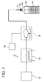
FIG. 3 , the sterilizing agent is evaporated by anevaporation device 21 before being supplied to the sterilizingagent supply pipe 31. - The
evaporation device 21 includes anair blower 22, aheater 23, and anevaporator 25, which are connected via piping in this order. - The
heater 23 heats the air blown from theair blower 22 and sends the heated air into theevaporator 25. The sterilizing agent is also supplied to the evaporator 25 from the sterilizingagent supply tank 12a. - Consequently, the sterilizing agent is heated by the blown hot air, and is evaporated or converted into mist. The sterilizing agent evaporated or converted into mist is fed from the
evaporator 25 to the sterilizingagent supply pipe 31, and is then injected from theinjection nozzle 35 into thecontainer 100 at 40°C to 70°C. - A
control device 18 provides an instruction to the sterilizingagent supply tank 12a in order to adjust the amount of the sterilizing agent to be supplied to thecontainer 100. Thecontrol device 18 can also specify the amount of the sterilizing agent adhering to theshoulder 102, for example in accordance with an electrical signal from anoptical sensor 45. Thecontrol device 18 can also calculate a deficient amount of the sterilizing agent. - In the first embodiment, the amount of the sterilizing agent adhering to the
shoulder 102 of thecontainer 100 is measured in accordance with light transparency to inject an appropriate amount of the sterilizing agent. - Essentially, the amount of the sterilizing agent in the
mouth 103 should be measured in order to supply the required amount of the sterilizing agent to themouth 103. However, light transparency or absorbance in themouth 103 is not stable, since themouth 103 is thicker than theshoulder 102 and amain body 101 and is threaded to be closed with a cap. Theshoulder 102 is located adjacent to themouth 103, and thus the adhesion amount of the sterilizing agent in theshoulder 102 relatively approximates to the adhesion amount of the sterilizing agent in themouth 103. Therefore in this embodiment, the adhesion amount of the sterilizing agent in theshoulder 102 is measured, and the adhesion level of the sterilizing agent in themouth 103 is estimated using the result of the measurement. - This embodiment is further described below with reference to
FIG. 4 andFIG. 5 . In the description, asterilization device 12A characteristic of the first embodiment is first described, and a process related to sterilization of thecontainer 100 is next described. - The sterilization process is typically performed for preparing to fill the
first container 100 with a beverage. The same statement is true for the second and third embodiments. - The
sterilization device 12A is provided with a sterilizing agent measuring device (sterilizing agent detecting means) 41, as illustrated inFIG. 4 . The sterilizingagent measuring device 41 includes alight source 43 and anoptical sensor 45 having a light receivingelement 44. - The
light receiving element 44 is connected to thecontrol device 18, and is arranged across thecontainer 100 from thelight source 43. Theoptical sensor 45 is positioned so that it is irradiated by thelight source 43 and the light receiving element can detect the inspection light passing through theshoulder 102 of thecontainer 100. - The amount of light detected by the
light receiving element 44 varies with the amount of the sterilizing agent adhering to theshoulder 102. Thelight receiving element 44 has a photoelectric conversion feature to send an electrical signal corresponding to an intensity of the received light to thecontrol device 18. Thecontrol device 18 specifies the amount of the sterilizing agent adhering to theshoulder 102 in accordance with the electrical signal received from thelight receiving element 44, as described in detail hereinafter. - The
light source 43 uses visible light having a center wavelength ranging from 400 nm to 600 nm. - The
container 100 is heated by the preheatingdevice 11 as a pretreatment for sterilizing thecontainer 100. - The preheating
device 11 injects hot gas to heat thecontainer 100. - A hot gas supply pipe, which is not shown, is inserted from the
mouth 103 into thecontainer 100, and hot gas is then injected near the bottom of thecontainer 100. The injected hot gas passes through the inside of thecontainer 100, in order of themain body 101, theshoulder 102, and themouth 103, and exhausts out of thecontainer 100. The hot gas heats the inside of thecontainer 100 between the injection and the exhaust, which warms up thecontainer 100. - The
heated container 100 is carried to thesterilization device 12A by the carryingstar wheels 17, as illustrated inFIG. 4 . - The sterilizing
agent supply pipe 31 is fixed to thecontainer 100 carried in thesterilization device 12A in an appropriate relative position. The sterilizing agent evaporated or converted into mist is then injected from theinjection nozzle 35 toward the bottom of thecontainer 100. - The injected sterilizing agent moves from the bottom of the
main body 101 and exhausts out of thecontainer 100. Between the injection and the exhaust, the sterilizing agent adheres to the inner surfaces of themain body 101, theshoulder 102, and themouth 103 in this order, and, as a result, sterilizes thecontainer 100. - After the injection of the sterilizing agent, the sterilizing
agent measuring device 41 measures the amount of the sterilizing agent adhering to theshoulder 102 of thecontainer 100. - Since the
mouth 103 opens to the outside and is narrower than themain body 101, the sterilizing agent passing through themouth 103 is accelerated. Thus, the sterilizing agent is hard to adhere to the inner surfaces of themouth 103. In this point, most of the sterilizing agent has been consumed due to adhesion to themain body 101, and the sterilizing agent that may reach themouth 103 has been reduced. For the above reasons, themouth 103 is least susceptible to sterilization in thecontainer 100. - As described above, it is difficult for an optical sensor, for example, to accurately detect the amount of light transmitted through the
mouth 103. In this embodiment, the sterilizingagent measuring device 41 therefore targets theshoulder 102 that is located near themouth 103. The sterilizingagent measuring device 41 measures the amount of light transmitted through theshoulder 102, which is represented by V11. The sterilizingagent measuring device 41 then sends an electric signal related to the amount of light V11 to thecontrol device 18. Thecontrol device 18 determines an amount of the sterilizing agent to be supplied to thecontainer 100 in the sterilizingagent supply part 30, based on the result of the detection by the sterilizingagent measuring device 41. - The
control device 18 in the first embodiment stores data related to the injection amount of the sterilizing agent required for reliable sterilization of themouth 103. This data, i.e. a prescribed amount, is represented by V10. - When the
control device 18 receives an amount of light V11 from the sterilizingagent measuring device 41, thecontrol device 18 determines the difference ΔV between the amount of light V11 and the prescribed amount V10 (formula 1).
- If ΔV is a negative value, the
control device 18 determines that the adhesion amount of the sterilizing agent is in a low level, and specifies the amount of the sterilizing agent to be increased in accordance with ΔV. On the other hand, if ΔV is a positive value, thecontrol device 18 determines that the adhesion amount of the sterilizing agent is in a high level, and specifies the amount of the sterilizing agent to be decreased in accordance with ΔV. For specifying the amount of the sterilizing agent to be increased or decreased, thecontrol device 18 may store table-type data and check ΔV against the data, for example. - The
control device 18 provides an instruction to the sterilizingagent supply tank 12a to operate so that the sterilizing agent in an amount in accordance with the specified amount is injected. - The sterilizing
agent supply tank 12a then increases or decreases the amount of the sterilizing agent to be supplied to theevaporator 25 under the instruction. Consequently, the sterilizing agent is injected from theinjection nozzle 35 so that an appropriate amount of the sterilizing agent adheres to themouth 103. - In the case of ΔV=0, the sterilizing agent is not increased or decreased. V10 is not limited to a specific value and may have a range of values. A mechanism, in which a product that gives ΔV deviating from a prescribed range of V10 is treated as a non-standard and removed the product from the production line, may be provided.
- In the
sterilization device 12A of this embodiment, the adhesion amount of the sterilizing agent in theshoulder 102 is measured. Although this is an indirect way, the adhesion amount of the sterilizing agent in themouth 103 can be calculated accurately. Only when the adhesion amount in themouth 103 is determined to be lower than the prescribed amount, the sterilizing agent to be supplied to thecontainer 100 is increased by the required amount. On the other hand, when the adhesion amount in themouth 103 is determined to be higher than the prescribed amount, the sterilizing agent to be supplied to thecontainer 100 is decreased by an appropriate amount. - Therefore, it is not necessary to supply an excess amount of the sterilizing agent to the
container 100, and the sterilization level of themouth 103 can be improved with the sterilizing agent supplied in an appropriate minimum amount. - This embodiment may be applied at any timing. For example, measurement may be performed at an early stage of a series of continuous beverage filling processes for the containers 100 (batch processing), and the result of the measurement may be reflected to the subsequent stage of the filling processes. Alternatively, the measurement may be performed on a prior batch processing, and the result of the measurement on the prior batch processing may be reflected after the prior batch processing ends and before the next batch processing begins.
- The shape of the container has been complicated with trends in the type of beverage to be filled or the appearance of the container. Thus, the single aseptic beverage filling apparatus 1 may be used for filling different shaped containers with a beverage.
- For some shapes of containers, the
mouth 103 does not necessarily have the lowest adhesion amount of the sterilizing agent in the container. - In the
container 100, the injected sterilizing agent is easier to adhere to a portion having a lower temperature, and is harder to adhere to a portion having a higher temperature. - Thus, in the second embodiment, a position, in which an adhesion amount of the sterilizing agent is to be measured, is determined based on the temperature distribution in the
preheated container 100, and the amount of the sterilizing agent to be injected is then determined in accordance with the adhesion amount of the sterilizing agent in the position. - In the description of this embodiment, the
container 100 having a similar shape to the container of the first embodiment is used for convenience. - A
sterilization device 12B is provided with a sterilizingagent measuring device 51, as illustrated inFIG. 6 . - The sterilizing
agent measuring device 51 includeslight sources 52, and a plurality of sensors 53 (53a to 53c) arranged in the height direction X of thecontainer 100, as illustrated inFIG. 7 . - Each
sensor 53 can detect an adhesion amount of the sterilizing agent adhering to a predetermined region. For example, thesensor 53c can detect the adhesion amount near the bottom of thecontainer 100. An optical sensor, for example, can be used to detect the adhesion amount of the sterilizing agent. - A sterilization process is now described. Since the procedure for preheating the
container 100 and the procedure for supplying the sterilizing agent are similar to those of the first embodiment, the following description is focused on differences from first embodiment for the sake of simplicity. - Temperature detecting means 55 determines the temperature distribution in the entire
preheated container 100 positioned in a predetermined position. Infrared thermography or a thermal image measuring device can be used as thetemperature detecting means 55, for example. Thetemperature detecting means 55 detects the portion (position) having the highest temperature in the container 100 (hereinafter referred to as PMAX). The position near the bottom corresponds to PMAX in this embodiment. - The
temperature detecting means 55 sends information about PMAX to thecontrol device 18. - Although PMAX in the
container 100 may be detected after thecontainer 100 is preheated, PMAX is preferably measured immediately before thecontainer 100 is carried to thesterilization device 12B. - The
control device 18 sends information about the position PMAX to the sterilizingagent measuring device 51. The sterilizingagent measuring device 51 measures the adhesion amount of the sterilizing agent V21 in the position PMAX, i.e. near the bottom of thecontainer 100, based on the information, and then sends information about the adhesion amount V21 to thecontrol device 18. - The
control device 18 stores information about the prescribed amount V20 for sterilizing thecontainer 100. - The
control device 18 checks the adhesion amount V21 against the prescribed amount V20. If the adhesion amount V21 is lower than the amount required for sterilization (the prescribed amount V20), thecontrol device 18 calculates the deficient amount of the sterilizing agent. Thecontrol device 18 then provides an instruction to the sterilizingagent supply tank 12a to operate so that the sterilizing agent is increased by the calculated amount. The sterilizingagent supply tank 12a received the instruction feeds the appropriate amount of the sterilizing agent into theevaporator 25. - In this way, the amount of the sterilizing agent to be supplied is determined, and the aseptic beverage filling apparatus 1 is then brought into operation.
- According to the
sterilization device 12B of this embodiment, the sterilizingagent measuring device 51 detects the adhesion amount of the sterilizing agent in the position having a relatively high temperature in thecontainer 100, and thecontrol device 18 then determines the amount of the sterilizing agent to be supplied by the sterilizingagent supply part 30 so that the prescribed amount of the sterilizing agent adheres to the position. Consequently, thecontainer 100 can be sterilized with an appropriate minimum amount of the sterilizing agent. - As mentioned above, even if the
container 100 has a complex shape, the inside of thecontainer 100 can be sterilized with an appropriate amount of the sterilizing agent. - In the third embodiment, an appropriate amount of the sterilizing agent to be injected is determined through observation of the
entire container 100 with the sterilizing agent adhering thereto. - A
sterilization device 12C of this embodiment is provided with imaging means 63, as illustrated inFIG. 8 . - The imaging means 63 includes a
light source 65 for irradiating themouth 103 of thecontainer 100 with light, acamera 67 for taking an image of thecontainer 100 irradiated with the light, and adisplay part 69 for displaying the image taken by thecamera 67. For example, a CCD camera can be used as thecamera 67. - When the
container 100 is irradiated with light from thelight source 65, the adhering sterilizing agent is scattered. Consequently, a luminance of a portion with the sterilizing agent adhering thereto is higher than a luminance of a portion with no sterilizing agent. Therefore, it is recognized that a portion with a higher luminance has a relatively high adhesion amount of the sterilizing agent compared to a portion with a lower luminance. - An image of the
container 100 is taken by thecamera 67 while thecontainer 100 is irradiated with the light, and the taken image is displayed on thedisplay part 69. - A sterilization process of this embodiment is now described.
- The
container 100 is heated by the preheatingdevice 11. Theheated container 100 is carried to thesterilization device 12C by the carryingstar wheels 17. The sterilizing agent is then injected from the injection nozzle of the sterilizingagent supply pipe 31 toward the bottom of thecontainer 100. - After the injection of the sterilizing agent, the image of the
container 100 with the sterilizing agent adhering thereto is displayed on thedisplay part 69 by the imaging means 63. The adhesion amount of the sterilizing agent can be determined from the luminance of the image. - For example in
FIG. 9A , the luminance decreases from the bottom to themouth 103, and scattering is not observed in theshoulder 102 and themouth 103. Thus, it is recognized that substantially no sterilizing agent adheres to theshoulder 102 and themouth 103. On the other hand,FIG. 9 shows that the luminance is high throughout theentire container 100. Thus, it is recognized that the sterilizing agent substantially entirely adheres to thecontainer 100. - Since a luminance in an image results from scattering caused by the sterilizing agent, there is a correlation between the adhesion amount of the sterilizing agent and the luminance of the image.
- The
control device 18 digitizes information about a luminance magnitude (threshold) that is shown when the prescribed amount V30 of the sterilizing agent adheres, and stores the digitized information in advance. Thecontrol device 18 analyzes the entirety of the image of thecontainer 100, and determines if the luminance reaches the threshold. If a portion having a luminance lower than the threshold is found in the image of thecontainer 100, thecontrol device 18 instructs the sterilizingagent supply tank 12a to increase the amount of the sterilizing agent to be supplied to theevaporator 25. - In this way, the amount of the sterilizing agent to be supplied is determined by the
control device 18, and the aseptic beverage filling apparatus 1 is then brought into operation. - According to the
sterilization device 12C of this embodiment, an operator can visually determine the adhesion level of the sterilizing agent throughout theentire container 100, and thus easily determine if thecontainer 100 is entirely sterilized. - If a portion having an insufficient adhesion amount of the sterilizing agent is detected, the
control device 18 operates to increase the amount of the sterilizing agent to be supplied by the required amount. Consequently, it is not necessary to supply an excess amount of the sterilizing agent, and the sterilization can be performed with an appropriate minimum amount of the sterilizing agent. - Other than the above, the configurations cited in the described embodiments can be selected or omitted, or can be modified to another configuration as appropriate, unless departing from the spirit of the present invention.
- Although sterilization, which is described as an example in the embodiments, is performed as a preparation to operate the aseptic beverage filling apparatus 1, sterilization may be performed during the operation of the aseptic beverage filling apparatus 1 in practice.
- In the third embodiment, the sterilizing agent may be mixed with a pigment to determine the adhesion state of the sterilizing agent from color of the pigment.
-
- 1 aseptic beverage filling apparatus
- 10 carrying-in conveyor
- 11 preheating device
- 12 sterilization device
- 12A, 12B, 12C sterilization device
- 12a sterilizing agent supply tank
- 13 rinse device
- 14 filling device
- 15 capper
- 16 carrying-out conveyor
- 17 carrying star wheel
- 18 control device
- 19 cap
- 20 base pedestal
- 21 evaporation device
- 22 air blower
- 23 heater
- 25 evaporator
- 30 sterilizing agent supply part
- 31 sterilizing agent supply pipe
- 35 injection nozzle
- 41 sterilizing agent measuring device (sterilizing agent detecting means)
- 43 light source
- 45 sensor
- 50 container supporting part
- 51 sterilizing agent measuring device
- 52 light source
- 53 sensor
- 55
temperature detecting means 63 imaging means - 65 light source
- 67 camera
- 69 display part
- 100 container
- 101 main body
- 102 shoulder
- 103 mouth
Claims (12)
- A sterilization device for a container, comprising:sterilizing agent supply means for supplying a sterilizing agent into the container having a mouth and a shoulder continuous with the mouth through the mouth, andsterilizing agent detecting means for detecting a level of the sterilizing agent adhering to the shoulder of the container, to which the sterilizing agent is supplied, by irradiating the shoulder with inspection light.
- A sterilization device for a container, comprising:temperature detecting means for detecting a high temperature position having a relatively high temperature in the container after the container is preheated,sterilizing agent supply means for supplying a sterilizing agent into the container after the high temperature position is detected,sterilizing agent measuring means for measuring an adhesion amount of the sterilizing agent adhering to the high temperature position after the sterilizing agent is supplied, andcontrol means for determining an amount of the sterilizing agent to be supplied to the container in the sterilizing agent supply means in accordance with the adhesion amount of the sterilizing agent in the high temperature position.
- A sterilization device for a container, comprising:sterilizing agent supply means for supplying a sterilizing agent into the container,imaging means for imaging the sterilizing agent adhering to the container after the sterilizing agent is supplied, andcontrol means for determining an amount of the sterilizing agent to be supplied to the container in the sterilizing agent supply means in accordance with data imaged by the imaging means.
- The sterilization device for the container according to claim 1, further comprising control means for determining an amount of the sterilizing agent to be supplied to the container in the sterilizing agent supply means based on the result of the detection by the sterilizing agent detecting means.
- The sterilization device for the container according to claim 1, wherein the mouth is thicker than the shoulder.
- The sterilization device for the container according to claim 1 or 5, wherein the mouth is threaded to be closed with a cap.
- The sterilization device for the container according to claim 2, wherein the temperature detecting means comprises a plurality of sensors, and the plurality of sensors are arranged in different positions in the height direction of the container.
- The sterilization device for the container according to claim 3, wherein the imaging means comprises:a light source for irradiating the container with light, anda camera for taking an image of the container irradiated with the light.
- The sterilization device for the container according to claim 8, wherein the imaging means further comprises:a display part for displaying the image of the container taken by the camera.
- The sterilization device for the container according to any one of claims 1 to 9, wherein the container is a beverage container.
- The sterilization device for the container according to claim 10, wherein the beverage container is made of plastic.
- The sterilization device for the container according to any one of claims 1 to 11, wherein the sterilizing agent is supplied into the container, the sterilizing agent being evaporated or converted into mist.
Applications Claiming Priority (2)
| Application Number | Priority Date | Filing Date | Title |
|---|---|---|---|
| JP2013232663 | 2013-11-11 | ||
| PCT/JP2014/005149 WO2015068334A1 (en) | 2013-11-11 | 2014-10-09 | Sterilization device for container |
Publications (3)
| Publication Number | Publication Date |
|---|---|
| EP3070011A1 true EP3070011A1 (en) | 2016-09-21 |
| EP3070011A4 EP3070011A4 (en) | 2017-11-29 |
| EP3070011B1 EP3070011B1 (en) | 2021-08-11 |
Family
ID=53041133
Family Applications (1)
| Application Number | Title | Priority Date | Filing Date |
|---|---|---|---|
| EP14859580.4A Active EP3070011B1 (en) | 2013-11-11 | 2014-10-09 | Sterilization device for container |
Country Status (3)
| Country | Link |
|---|---|
| EP (1) | EP3070011B1 (en) |
| JP (1) | JP6072291B2 (en) |
| WO (1) | WO2015068334A1 (en) |
Cited By (1)
| Publication number | Priority date | Publication date | Assignee | Title |
|---|---|---|---|---|
| US10905786B2 (en) | 2017-03-27 | 2021-02-02 | Regeneron Pharmaceuticals, Inc. | Sterilisation method |
Families Citing this family (1)
| Publication number | Priority date | Publication date | Assignee | Title |
|---|---|---|---|---|
| JP2023108722A (en) * | 2022-01-26 | 2023-08-07 | 三菱重工機械システム株式会社 | Temperature information acquisition method for article to be conveyed, quality determination method for sterile condition, and sterile filling system |
Family Cites Families (16)
| Publication number | Priority date | Publication date | Assignee | Title |
|---|---|---|---|---|
| JPS55104670A (en) * | 1979-02-06 | 1980-08-11 | Dainippon Printing Co Ltd | Controlling method of atomizing amount of disinfectant liquid |
| DE4114889C2 (en) * | 1991-05-07 | 1994-11-10 | Kronseder Maschf Krones | Method and device for filling and closing containers |
| JP3184578B2 (en) * | 1991-11-19 | 2001-07-09 | 大日本印刷株式会社 | Liquid adhesion amount measurement method |
| JP3678803B2 (en) * | 1995-08-07 | 2005-08-03 | 大日本印刷株式会社 | Spray monitoring method and apparatus |
| JP3393088B2 (en) * | 1999-06-22 | 2003-04-07 | 株式会社キリンテクノシステム | Cleaning liquid ejection failure detection device |
| JP4408194B2 (en) * | 2002-09-10 | 2010-02-03 | 大日本印刷株式会社 | Sterilization method and apparatus |
| ITPR20020066A1 (en) * | 2002-11-18 | 2004-05-19 | Antonio Rigano' | RINSING AND / OR STERILIZING MACHINE FOR PLASTIC OR GLASS BOTTLES. |
| JP4421284B2 (en) * | 2003-12-16 | 2010-02-24 | アサヒ飲料株式会社 | Cleaning device |
| US20070253863A1 (en) * | 2006-04-27 | 2007-11-01 | Toyo Seikan Kaisha, Ltd. | Method and apparatus for sterilizing a container |
| JP5019155B2 (en) * | 2006-08-14 | 2012-09-05 | 大日本印刷株式会社 | Sterilization apparatus and sterilization method |
| JP5332603B2 (en) * | 2008-12-26 | 2013-11-06 | 大日本印刷株式会社 | Beverage filling method and apparatus |
| CN103588154B (en) * | 2008-05-20 | 2016-07-27 | 大日本印刷株式会社 | Beverage filling device |
| WO2013021882A1 (en) * | 2011-08-05 | 2013-02-14 | 大日本印刷株式会社 | Beverage filling method and device |
| CN105730783A (en) * | 2011-10-25 | 2016-07-06 | 大日本印刷株式会社 | Beverage filling method and apparatus |
| DE102012103023A1 (en) * | 2012-04-05 | 2013-10-10 | Krones Ag | Device for sterilizing containers e.g. plastic bottles in beverage manufacturing industry, has control device whose image pickup device receives image of exit region in which charge carrier emerges from chamber |
| JP5725097B2 (en) * | 2013-07-31 | 2015-05-27 | 大日本印刷株式会社 | Beverage filling equipment |
-
2014
- 2014-10-09 EP EP14859580.4A patent/EP3070011B1/en active Active
- 2014-10-09 WO PCT/JP2014/005149 patent/WO2015068334A1/en not_active Ceased
- 2014-10-09 JP JP2015546282A patent/JP6072291B2/en active Active
Cited By (2)
| Publication number | Priority date | Publication date | Assignee | Title |
|---|---|---|---|---|
| US10905786B2 (en) | 2017-03-27 | 2021-02-02 | Regeneron Pharmaceuticals, Inc. | Sterilisation method |
| US10918754B2 (en) | 2017-03-27 | 2021-02-16 | Regeneron Pharmaceuticals, Inc. | Sterilisation method |
Also Published As
| Publication number | Publication date |
|---|---|
| WO2015068334A1 (en) | 2015-05-14 |
| EP3070011B1 (en) | 2021-08-11 |
| JP6072291B2 (en) | 2017-02-01 |
| EP3070011A4 (en) | 2017-11-29 |
| JPWO2015068334A1 (en) | 2017-03-09 |
Similar Documents
| Publication | Publication Date | Title |
|---|---|---|
| US10670336B2 (en) | Method and system for freeze-drying injectable compositions, in particular pharmaceutical compositions | |
| CN101448728B (en) | Method and device for sterilizing bottles or similar containers | |
| CN104944346B (en) | Beverage filling method and beverage filling device | |
| JP5784275B2 (en) | Beverage filling method and apparatus | |
| EP3070011B1 (en) | Sterilization device for container | |
| US12145829B2 (en) | Aseptic filling method and aseptic filling machine | |
| EP4699783A2 (en) | Aseptic filling method and aseptic filling machine | |
| CN105939937A (en) | Container sterilization method and device | |
| JP2020506851A (en) | Apparatus and method for sterilizing a plastic preform for pre-inspection of the plastic preform | |
| CN101610795A (en) | The method used to sterilize the container | |
| US12209050B2 (en) | Method and installation for dealkalizing glass containers using liquid | |
| US20190210747A1 (en) | Aseptic filling apparatus | |
| US6244275B1 (en) | Method and device for controlling processing of the inside areas of bottles or the like | |
| US20070253863A1 (en) | Method and apparatus for sterilizing a container | |
| JP5528247B2 (en) | Electron beam irradiation device | |
| JP2014221671A (en) | Method and apparatus for filling acid beverage | |
| JP4884805B2 (en) | Liquid filling device | |
| JP6191679B2 (en) | Beverage filling method and apparatus | |
| US20240197935A1 (en) | Apparatus and method for treating the inner walls of containers | |
| JP2006248617A (en) | Packaging material sterilization method | |
| JPH0565148A (en) | Method and apparatus for sterilizing packaging material |
Legal Events
| Date | Code | Title | Description |
|---|---|---|---|
| PUAI | Public reference made under article 153(3) epc to a published international application that has entered the european phase |
Free format text: ORIGINAL CODE: 0009012 |
|
| 17P | Request for examination filed |
Effective date: 20160412 |
|
| AK | Designated contracting states |
Kind code of ref document: A1 Designated state(s): AL AT BE BG CH CY CZ DE DK EE ES FI FR GB GR HR HU IE IS IT LI LT LU LV MC MK MT NL NO PL PT RO RS SE SI SK SM TR |
|
| AX | Request for extension of the european patent |
Extension state: BA ME |
|
| RAP1 | Party data changed (applicant data changed or rights of an application transferred) |
Owner name: MITSUBISHI HEAVY INDUSTRIES FOOD & PACKAGING MACHI |
|
| DAX | Request for extension of the european patent (deleted) | ||
| RAP1 | Party data changed (applicant data changed or rights of an application transferred) |
Owner name: MITSUBISHI HEAVY INDUSTRIES MECHATRONICS SYSTEMS, |
|
| RIC1 | Information provided on ipc code assigned before grant |
Ipc: B67C 7/00 20060101ALI20170717BHEP Ipc: B65B 55/04 20060101ALI20170717BHEP Ipc: B65B 55/10 20060101AFI20170717BHEP |
|
| A4 | Supplementary search report drawn up and despatched |
Effective date: 20171102 |
|
| RIC1 | Information provided on ipc code assigned before grant |
Ipc: B65B 55/10 20060101AFI20171025BHEP Ipc: B65B 55/04 20060101ALI20171025BHEP Ipc: B67C 7/00 20060101ALI20171025BHEP |
|
| RAP1 | Party data changed (applicant data changed or rights of an application transferred) |
Owner name: MITSUBISHI HEAVY INDUSTRIES MACHINERY SYSTEMS, LTD |
|
| STAA | Information on the status of an ep patent application or granted ep patent |
Free format text: STATUS: EXAMINATION IS IN PROGRESS |
|
| 17Q | First examination report despatched |
Effective date: 20201020 |
|
| REG | Reference to a national code |
Ref country code: DE Ref legal event code: R079 Ref document number: 602014079430 Country of ref document: DE Free format text: PREVIOUS MAIN CLASS: B65B0055100000 Ipc: A61L0002280000 |
|
| GRAP | Despatch of communication of intention to grant a patent |
Free format text: ORIGINAL CODE: EPIDOSNIGR1 |
|
| STAA | Information on the status of an ep patent application or granted ep patent |
Free format text: STATUS: GRANT OF PATENT IS INTENDED |
|
| RIC1 | Information provided on ipc code assigned before grant |
Ipc: A61L 2/28 20060101AFI20210420BHEP |
|
| INTG | Intention to grant announced |
Effective date: 20210504 |
|
| GRAS | Grant fee paid |
Free format text: ORIGINAL CODE: EPIDOSNIGR3 |
|
| GRAA | (expected) grant |
Free format text: ORIGINAL CODE: 0009210 |
|
| STAA | Information on the status of an ep patent application or granted ep patent |
Free format text: STATUS: THE PATENT HAS BEEN GRANTED |
|
| AK | Designated contracting states |
Kind code of ref document: B1 Designated state(s): AL AT BE BG CH CY CZ DE DK EE ES FI FR GB GR HR HU IE IS IT LI LT LU LV MC MK MT NL NO PL PT RO RS SE SI SK SM TR |
|
| REG | Reference to a national code |
Ref country code: CH Ref legal event code: EP |
|
| REG | Reference to a national code |
Ref country code: DE Ref legal event code: R096 Ref document number: 602014079430 Country of ref document: DE |
|
| REG | Reference to a national code |
Ref country code: IE Ref legal event code: FG4D Ref country code: AT Ref legal event code: REF Ref document number: 1418704 Country of ref document: AT Kind code of ref document: T Effective date: 20210915 |
|
| REG | Reference to a national code |
Ref country code: LT Ref legal event code: MG9D |
|
| REG | Reference to a national code |
Ref country code: NL Ref legal event code: MP Effective date: 20210811 |
|
| REG | Reference to a national code |
Ref country code: AT Ref legal event code: MK05 Ref document number: 1418704 Country of ref document: AT Kind code of ref document: T Effective date: 20210811 |
|
| PG25 | Lapsed in a contracting state [announced via postgrant information from national office to epo] |
Ref country code: HR Free format text: LAPSE BECAUSE OF FAILURE TO SUBMIT A TRANSLATION OF THE DESCRIPTION OR TO PAY THE FEE WITHIN THE PRESCRIBED TIME-LIMIT Effective date: 20210811 Ref country code: RS Free format text: LAPSE BECAUSE OF FAILURE TO SUBMIT A TRANSLATION OF THE DESCRIPTION OR TO PAY THE FEE WITHIN THE PRESCRIBED TIME-LIMIT Effective date: 20210811 Ref country code: SE Free format text: LAPSE BECAUSE OF FAILURE TO SUBMIT A TRANSLATION OF THE DESCRIPTION OR TO PAY THE FEE WITHIN THE PRESCRIBED TIME-LIMIT Effective date: 20210811 Ref country code: LT Free format text: LAPSE BECAUSE OF FAILURE TO SUBMIT A TRANSLATION OF THE DESCRIPTION OR TO PAY THE FEE WITHIN THE PRESCRIBED TIME-LIMIT Effective date: 20210811 Ref country code: AT Free format text: LAPSE BECAUSE OF FAILURE TO SUBMIT A TRANSLATION OF THE DESCRIPTION OR TO PAY THE FEE WITHIN THE PRESCRIBED TIME-LIMIT Effective date: 20210811 Ref country code: BG Free format text: LAPSE BECAUSE OF FAILURE TO SUBMIT A TRANSLATION OF THE DESCRIPTION OR TO PAY THE FEE WITHIN THE PRESCRIBED TIME-LIMIT Effective date: 20211111 Ref country code: NO Free format text: LAPSE BECAUSE OF FAILURE TO SUBMIT A TRANSLATION OF THE DESCRIPTION OR TO PAY THE FEE WITHIN THE PRESCRIBED TIME-LIMIT Effective date: 20211111 Ref country code: PT Free format text: LAPSE BECAUSE OF FAILURE TO SUBMIT A TRANSLATION OF THE DESCRIPTION OR TO PAY THE FEE WITHIN THE PRESCRIBED TIME-LIMIT Effective date: 20211213 Ref country code: ES Free format text: LAPSE BECAUSE OF FAILURE TO SUBMIT A TRANSLATION OF THE DESCRIPTION OR TO PAY THE FEE WITHIN THE PRESCRIBED TIME-LIMIT Effective date: 20210811 Ref country code: FI Free format text: LAPSE BECAUSE OF FAILURE TO SUBMIT A TRANSLATION OF THE DESCRIPTION OR TO PAY THE FEE WITHIN THE PRESCRIBED TIME-LIMIT Effective date: 20210811 |
|
| PG25 | Lapsed in a contracting state [announced via postgrant information from national office to epo] |
Ref country code: PL Free format text: LAPSE BECAUSE OF FAILURE TO SUBMIT A TRANSLATION OF THE DESCRIPTION OR TO PAY THE FEE WITHIN THE PRESCRIBED TIME-LIMIT Effective date: 20210811 Ref country code: LV Free format text: LAPSE BECAUSE OF FAILURE TO SUBMIT A TRANSLATION OF THE DESCRIPTION OR TO PAY THE FEE WITHIN THE PRESCRIBED TIME-LIMIT Effective date: 20210811 Ref country code: GR Free format text: LAPSE BECAUSE OF FAILURE TO SUBMIT A TRANSLATION OF THE DESCRIPTION OR TO PAY THE FEE WITHIN THE PRESCRIBED TIME-LIMIT Effective date: 20211112 |
|
| PG25 | Lapsed in a contracting state [announced via postgrant information from national office to epo] |
Ref country code: NL Free format text: LAPSE BECAUSE OF FAILURE TO SUBMIT A TRANSLATION OF THE DESCRIPTION OR TO PAY THE FEE WITHIN THE PRESCRIBED TIME-LIMIT Effective date: 20210811 |
|
| PG25 | Lapsed in a contracting state [announced via postgrant information from national office to epo] |
Ref country code: DK Free format text: LAPSE BECAUSE OF FAILURE TO SUBMIT A TRANSLATION OF THE DESCRIPTION OR TO PAY THE FEE WITHIN THE PRESCRIBED TIME-LIMIT Effective date: 20210811 |
|
| REG | Reference to a national code |
Ref country code: DE Ref legal event code: R097 Ref document number: 602014079430 Country of ref document: DE |
|
| REG | Reference to a national code |
Ref country code: CH Ref legal event code: PL |
|
| PG25 | Lapsed in a contracting state [announced via postgrant information from national office to epo] |
Ref country code: SM Free format text: LAPSE BECAUSE OF FAILURE TO SUBMIT A TRANSLATION OF THE DESCRIPTION OR TO PAY THE FEE WITHIN THE PRESCRIBED TIME-LIMIT Effective date: 20210811 Ref country code: SK Free format text: LAPSE BECAUSE OF FAILURE TO SUBMIT A TRANSLATION OF THE DESCRIPTION OR TO PAY THE FEE WITHIN THE PRESCRIBED TIME-LIMIT Effective date: 20210811 Ref country code: RO Free format text: LAPSE BECAUSE OF FAILURE TO SUBMIT A TRANSLATION OF THE DESCRIPTION OR TO PAY THE FEE WITHIN THE PRESCRIBED TIME-LIMIT Effective date: 20210811 Ref country code: EE Free format text: LAPSE BECAUSE OF FAILURE TO SUBMIT A TRANSLATION OF THE DESCRIPTION OR TO PAY THE FEE WITHIN THE PRESCRIBED TIME-LIMIT Effective date: 20210811 Ref country code: CZ Free format text: LAPSE BECAUSE OF FAILURE TO SUBMIT A TRANSLATION OF THE DESCRIPTION OR TO PAY THE FEE WITHIN THE PRESCRIBED TIME-LIMIT Effective date: 20210811 Ref country code: AL Free format text: LAPSE BECAUSE OF FAILURE TO SUBMIT A TRANSLATION OF THE DESCRIPTION OR TO PAY THE FEE WITHIN THE PRESCRIBED TIME-LIMIT Effective date: 20210811 |
|
| PLBE | No opposition filed within time limit |
Free format text: ORIGINAL CODE: 0009261 |
|
| STAA | Information on the status of an ep patent application or granted ep patent |
Free format text: STATUS: NO OPPOSITION FILED WITHIN TIME LIMIT |
|
| REG | Reference to a national code |
Ref country code: BE Ref legal event code: MM Effective date: 20211031 |
|
| PG25 | Lapsed in a contracting state [announced via postgrant information from national office to epo] |
Ref country code: MC Free format text: LAPSE BECAUSE OF FAILURE TO SUBMIT A TRANSLATION OF THE DESCRIPTION OR TO PAY THE FEE WITHIN THE PRESCRIBED TIME-LIMIT Effective date: 20210811 |
|
| 26N | No opposition filed |
Effective date: 20220512 |
|
| GBPC | Gb: european patent ceased through non-payment of renewal fee |
Effective date: 20211111 |
|
| PG25 | Lapsed in a contracting state [announced via postgrant information from national office to epo] |
Ref country code: LU Free format text: LAPSE BECAUSE OF NON-PAYMENT OF DUE FEES Effective date: 20211009 Ref country code: BE Free format text: LAPSE BECAUSE OF NON-PAYMENT OF DUE FEES Effective date: 20211031 |
|
| PG25 | Lapsed in a contracting state [announced via postgrant information from national office to epo] |
Ref country code: SI Free format text: LAPSE BECAUSE OF FAILURE TO SUBMIT A TRANSLATION OF THE DESCRIPTION OR TO PAY THE FEE WITHIN THE PRESCRIBED TIME-LIMIT Effective date: 20210811 Ref country code: LI Free format text: LAPSE BECAUSE OF NON-PAYMENT OF DUE FEES Effective date: 20211031 Ref country code: CH Free format text: LAPSE BECAUSE OF NON-PAYMENT OF DUE FEES Effective date: 20211031 |
|
| PG25 | Lapsed in a contracting state [announced via postgrant information from national office to epo] |
Ref country code: IE Free format text: LAPSE BECAUSE OF NON-PAYMENT OF DUE FEES Effective date: 20211009 Ref country code: GB Free format text: LAPSE BECAUSE OF NON-PAYMENT OF DUE FEES Effective date: 20211111 |
|
| PG25 | Lapsed in a contracting state [announced via postgrant information from national office to epo] |
Ref country code: HU Free format text: LAPSE BECAUSE OF FAILURE TO SUBMIT A TRANSLATION OF THE DESCRIPTION OR TO PAY THE FEE WITHIN THE PRESCRIBED TIME-LIMIT; INVALID AB INITIO Effective date: 20141009 |
|
| PG25 | Lapsed in a contracting state [announced via postgrant information from national office to epo] |
Ref country code: CY Free format text: LAPSE BECAUSE OF FAILURE TO SUBMIT A TRANSLATION OF THE DESCRIPTION OR TO PAY THE FEE WITHIN THE PRESCRIBED TIME-LIMIT Effective date: 20210811 |
|
| PGFP | Annual fee paid to national office [announced via postgrant information from national office to epo] |
Ref country code: IT Payment date: 20230913 Year of fee payment: 10 |
|
| PG25 | Lapsed in a contracting state [announced via postgrant information from national office to epo] |
Ref country code: MK Free format text: LAPSE BECAUSE OF FAILURE TO SUBMIT A TRANSLATION OF THE DESCRIPTION OR TO PAY THE FEE WITHIN THE PRESCRIBED TIME-LIMIT Effective date: 20210811 |
|
| PG25 | Lapsed in a contracting state [announced via postgrant information from national office to epo] |
Ref country code: TR Free format text: LAPSE BECAUSE OF FAILURE TO SUBMIT A TRANSLATION OF THE DESCRIPTION OR TO PAY THE FEE WITHIN THE PRESCRIBED TIME-LIMIT Effective date: 20210811 |
|
| PG25 | Lapsed in a contracting state [announced via postgrant information from national office to epo] |
Ref country code: MT Free format text: LAPSE BECAUSE OF FAILURE TO SUBMIT A TRANSLATION OF THE DESCRIPTION OR TO PAY THE FEE WITHIN THE PRESCRIBED TIME-LIMIT Effective date: 20210811 |
|
| PG25 | Lapsed in a contracting state [announced via postgrant information from national office to epo] |
Ref country code: IT Free format text: LAPSE BECAUSE OF NON-PAYMENT OF DUE FEES Effective date: 20241009 |
|
| PGFP | Annual fee paid to national office [announced via postgrant information from national office to epo] |
Ref country code: FR Payment date: 20250908 Year of fee payment: 12 |
|
| PGFP | Annual fee paid to national office [announced via postgrant information from national office to epo] |
Ref country code: DE Payment date: 20250902 Year of fee payment: 12 |