EP3069941A1 - Connection device between a windscreen wiper and an adapter of an arm - Google Patents
Connection device between a windscreen wiper and an adapter of an arm Download PDFInfo
- Publication number
- EP3069941A1 EP3069941A1 EP16157010.6A EP16157010A EP3069941A1 EP 3069941 A1 EP3069941 A1 EP 3069941A1 EP 16157010 A EP16157010 A EP 16157010A EP 3069941 A1 EP3069941 A1 EP 3069941A1
- Authority
- EP
- European Patent Office
- Prior art keywords
- component
- platform
- wiper
- adapter
- wall
- Prior art date
- Legal status (The legal status is an assumption and is not a legal conclusion. Google has not performed a legal analysis and makes no representation as to the accuracy of the status listed.)
- Granted
Links
Images


Classifications
-
- B—PERFORMING OPERATIONS; TRANSPORTING
- B60—VEHICLES IN GENERAL
- B60S—SERVICING, CLEANING, REPAIRING, SUPPORTING, LIFTING, OR MANOEUVRING OF VEHICLES, NOT OTHERWISE PROVIDED FOR
- B60S1/00—Cleaning of vehicles
- B60S1/02—Cleaning windscreens, windows or optical devices
- B60S1/04—Wipers or the like, e.g. scrapers
- B60S1/32—Wipers or the like, e.g. scrapers characterised by constructional features of wiper blade arms or blades
- B60S1/40—Connections between blades and arms
-
- B—PERFORMING OPERATIONS; TRANSPORTING
- B60—VEHICLES IN GENERAL
- B60S—SERVICING, CLEANING, REPAIRING, SUPPORTING, LIFTING, OR MANOEUVRING OF VEHICLES, NOT OTHERWISE PROVIDED FOR
- B60S1/00—Cleaning of vehicles
- B60S1/02—Cleaning windscreens, windows or optical devices
- B60S1/46—Cleaning windscreens, windows or optical devices using liquid; Windscreen washers
- B60S1/48—Liquid supply therefor
- B60S1/52—Arrangement of nozzles; Liquid spreading means
- B60S1/522—Arrangement of nozzles; Liquid spreading means moving liquid spreading means, e.g. arranged in wiper arms
- B60S1/524—Arrangement of nozzles; Liquid spreading means moving liquid spreading means, e.g. arranged in wiper arms arranged in wiper blades
-
- B—PERFORMING OPERATIONS; TRANSPORTING
- B60—VEHICLES IN GENERAL
- B60S—SERVICING, CLEANING, REPAIRING, SUPPORTING, LIFTING, OR MANOEUVRING OF VEHICLES, NOT OTHERWISE PROVIDED FOR
- B60S1/00—Cleaning of vehicles
- B60S1/02—Cleaning windscreens, windows or optical devices
- B60S1/04—Wipers or the like, e.g. scrapers
- B60S1/32—Wipers or the like, e.g. scrapers characterised by constructional features of wiper blade arms or blades
- B60S1/38—Wiper blades
- B60S1/3848—Flat-type wiper blade, i.e. without harness
- B60S1/3849—Connectors therefor; Connection to wiper arm; Attached to blade
- B60S1/3862—Transport of liquid there through
-
- B—PERFORMING OPERATIONS; TRANSPORTING
- B60—VEHICLES IN GENERAL
- B60S—SERVICING, CLEANING, REPAIRING, SUPPORTING, LIFTING, OR MANOEUVRING OF VEHICLES, NOT OTHERWISE PROVIDED FOR
- B60S1/00—Cleaning of vehicles
- B60S1/02—Cleaning windscreens, windows or optical devices
- B60S1/04—Wipers or the like, e.g. scrapers
- B60S1/32—Wipers or the like, e.g. scrapers characterised by constructional features of wiper blade arms or blades
- B60S1/38—Wiper blades
- B60S1/3848—Flat-type wiper blade, i.e. without harness
- B60S1/3849—Connectors therefor; Connection to wiper arm; Attached to blade
- B60S1/3863—Connectors having a spoiler
-
- B—PERFORMING OPERATIONS; TRANSPORTING
- B60—VEHICLES IN GENERAL
- B60S—SERVICING, CLEANING, REPAIRING, SUPPORTING, LIFTING, OR MANOEUVRING OF VEHICLES, NOT OTHERWISE PROVIDED FOR
- B60S1/00—Cleaning of vehicles
- B60S1/02—Cleaning windscreens, windows or optical devices
- B60S1/46—Cleaning windscreens, windows or optical devices using liquid; Windscreen washers
- B60S1/48—Liquid supply therefor
- B60S1/52—Arrangement of nozzles; Liquid spreading means
- B60S1/522—Arrangement of nozzles; Liquid spreading means moving liquid spreading means, e.g. arranged in wiper arms
-
- B—PERFORMING OPERATIONS; TRANSPORTING
- B60—VEHICLES IN GENERAL
- B60S—SERVICING, CLEANING, REPAIRING, SUPPORTING, LIFTING, OR MANOEUVRING OF VEHICLES, NOT OTHERWISE PROVIDED FOR
- B60S1/00—Cleaning of vehicles
- B60S1/02—Cleaning windscreens, windows or optical devices
- B60S1/04—Wipers or the like, e.g. scrapers
- B60S1/32—Wipers or the like, e.g. scrapers characterised by constructional features of wiper blade arms or blades
- B60S1/40—Connections between blades and arms
- B60S1/4038—Connections between blades and arms for arms provided with a channel-shaped end
- B60S1/4045—Connections between blades and arms for arms provided with a channel-shaped end comprising a detachable intermediate element mounted on the channel-shaped end
- B60S1/4048—Connections between blades and arms for arms provided with a channel-shaped end comprising a detachable intermediate element mounted on the channel-shaped end the element being provided with retention means co-operating with the channel-shaped end of the arm
- B60S2001/4054—Connections between blades and arms for arms provided with a channel-shaped end comprising a detachable intermediate element mounted on the channel-shaped end the element being provided with retention means co-operating with the channel-shaped end of the arm the intermediate element engaging the back part of the arm
Definitions
- the field of the present invention is that of equipment for vehicles, and more particularly that of equipment for wiping the windows of a vehicle.
- the present invention relates to a connection device participating in a mechanical connection between a wiper arm and a wiper blade adapted to wipe a windshield or a rear window of the vehicle.
- Motor vehicles are commonly equipped with a windshield wiper system to sweep and wash the windshield and to prevent the driver's vision from being disturbed.
- These wipers are conventionally driven by an arm performing an angular reciprocating movement and comprise elongate brushes, themselves carrying scraper blades made of an elastic material. These blades rub against the windshield and evacuate the water by bringing it out of the driver's field of vision.
- the brushes are made in the form, or, in a conventional version, articulated hoists that hold the scraper blade in several discrete places, or, in a newer version called "flat blade” (for "flat blade”), a semi-rigid set that keeps the scraper blade along its entire length.
- the blade is attached to the rotating arm of the wiper by a set consisting of a mechanical connector and an adapter.
- the mechanical connector is a part that is crimped directly on the flat broom, while the adapter is an intermediate piece that allows the attachment of the connector on the arm of the wiper.
- the wiper device described above is commonly combined with a system for projecting a liquid onto the windshield.
- a projection system takes for example the form of nozzles installed on the hood of the vehicle.
- a disadvantage of this type of system lies in the fact that it is necessary to provide holes in the hood.
- Another disadvantage inherent in this technical solution lies in the distance that separates the nozzle from the surface of the windshield that it is necessary to cover with liquid. The flow of air on the hood and on the windshield when the vehicle is in motion disrupts the projection of liquid.
- the wiper blade includes a spray boom of the washing liquid on the windshield.
- a ramp is formed by a duct which extends along the wiper blade along a main longitudinal axis of extension of this blade.
- This duct is provided with projection orifices distributed along this axis.
- the object of the present invention is therefore to solve the disadvantages described above by designing a liquid projection system which does not suffer or little airflow disturbances and which has a cost as low as possible, while ensuring the best function projection of the liquid on the windshield.
- connection device otherwise known as a connection connector, capable of connecting a wiper blade of a window of a vehicle to a wiper arm, comprising means for securing to the wiper blade.
- wiper surmounted by means of connection to an adapter connected to the wiper arm, innovative in that it comprises a platform derived from the securing means and a component that originates on the platform, and in which the component, the platform and the connecting means delimit at least partially a housing adapted to receive at least a portion of the adapter.
- a projection orifice of a liquid is formed on the component.
- the component becomes a liquid projection component.
- a projection orifice such an expression covering the case of a single orifice or the case of a plurality of openings.
- At least one duct is formed in the component for transporting the liquid from a liquid inlet to said orifice.
- the connecting means comprises pivoting means adapted to rotate about an axis the connecting means relative to the adapter.
- the projection orifice is provided at the axis, for example +/- 2 mm from the axis, or beyond it, away from the platform.
- the component is delimited by an inner wall facing the housing, an outer wall, at least two side walls joining the inner wall to the outer wall and a distal wall opposite the platform, the orifice projection being provided exclusively in the outer wall and / or in the lateral wall or walls.
- a supply cannula is formed on one of the side walls defining the component. This feeding cannula delimits the liquid inlet mentioned above.
- the connecting means extends in a direction perpendicular to a wiping plane of the wiper blade, the component extending in a second direction. An angle is then formed between the first direction and the second direction and this angle is between 15 ° and 55 °.
- the securing means comprises at least two hooks adapted to encase at least partly a constituent structure of the wiper blade.
- Each of the hooks can then take the form of a "U", a first face of the "U” being adapted to be in contact with an upper face of the structure of the wiper blade, a second face of the "U” being suitable to be in contact with a lower face of the wiper blade structure and a third face connects the first face to the second face.
- the securing means, the connecting means and the platform are in one piece, that is to say molded simultaneously from the same polymer material.
- the component and the platform are in one piece. It is understood here that the component and the platform form a unitary unit, for example from the same molding from the same polymer material, optionally together with the securing means and the connecting means.
- fixing means are sliding.
- a method of assembling the component on the platform where the component is translated longitudinally on the platform is here provided.
- the fastening means are clipping.
- a method of assembling the component on the platform where the component is rotated about a longitudinal axis of the platform is considered here.
- the invention also relates to a wiper blade comprising a blade adapted to be applied against a window of a vehicle, a flexible structure connected to the blade and a connection device comprising at least one of the features presented above such a connection device being secured to the flexible structure in the center thereof, particularly substantially in the center thereof, in a longitudinal direction of the flexible structure.
- Such a broom may comprise an adapter rotatably connected with the connecting device, the adapter extends at least partly in the housing.
- the invention also covers a wiper system of a window of a vehicle comprising a wiper blade as evoked above and a wiper arm, wherein a portion of the wiper arm extends in the accommodation.
- the wiper blade By using a piece present on the wiper blade to implement the liquid projection, it ensures a proximity that limits the disturbances resulting from the flow of air.
- the invention is also economically advantageous since the liquid splash function is grouped on the connection device used to connect the wiper blade to the drive arm.
- connection device The advantages of the conformation of the connection device according to the invention reside in the first place in a protection of the connection between the adapter and the connection device against external aggression and impurities.
- the component is a liquid projection component because it comprises at least one projection orifice
- an advantage lies in the possibility of locating the orifice away from the glass. This allows to open the projection angles and thus cover in liquid the entire surface of the glass swept by the wiper blade by means of a single projection component connected to the connection device.
- the longitudinal or lateral designations refer to the orientation of the wiper blade or the connection device according to the invention.
- the longitudinal direction corresponds to the main axis of the wiper blade in which it extends
- the lateral orientations correspond to intersecting lines, that is to say which cross the longitudinal direction, in particular perpendicular to the longitudinal axis of the wiper blade in its plane of rotation.
- the outer or inner names are assessed relative to the attachment point of the wiper blade on the wiper arm, the inner name corresponding to the part where the arm and a half-broom extend.
- the directions referenced as higher or lower correspond to orientations perpendicular to the plane of rotation of the wiper blade, the lower denomination containing the plane of the windshield.
- a wiper 2 is used to scrape a window of a vehicle and move out of the field of view of a driver the water deposited on the window.
- the wiper 2 consists of a connection device 1 according to the invention, capped by an adapter 5 and whose function is to interface the same connection device 1 with several types of wiper arm.
- the wiper blade 2 also comprises at least one flexible support 23, one or more air deflectors 29, a friction blade 22 and at least one, or even two end caps 30 installed on each end portion of the flexible support 23.
- the flexible support 23 may take the form of a single flat and elastic metal band.
- the flexible support 23 may be formed by two metal strips and elastic each housed in a groove formed on either side of the blade 22. In the two cases above, in the rest state, a such metal strip is recognizable in that it is bent in a plane perpendicular to a longitudinal direction of the strip.
- the function of such a metal strip, whether single or double, is to distribute the support forces along the blade 22 generated by the connection means 1 attached to the flexible support 23 in the center, longitudinally, of the broom wiper 2.
- the figure 2 shows an end 31 of the wiper arm 24.
- This end 31 has a U-shaped section with a back 32 and two arms 33 and 25 from the back 32.
- this adapter 5 comprises a body received in the interior volume and the end of which is a head 35.
- This head closes an end portion of the adapter 5 and has a wall 36 aligned with the U-shaped profile of the end 31.
- a slot 46 is formed in the head 35 of the adapter 5 to prevent mechanical interference with the air deflector located outside the wiper blade 2.
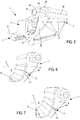
- connection device 1 illustrates in greater detail an example of the structure of the connection device 1 according to the invention, equipped with the adapter 5 and the end 31 of the arm 24.
- the connection device 1 comprises a securing means 3 to the broom. wiping surmounted by a connecting means 4 to the adapter, the latter being connected to the wiper arm 24 via the adapter 5.
- the securing means 3 has the function of gripping and fixing the connection device 1 on a structural zone of the wiper blade, such a zone being formed substantially in the center, along the longitudinal axis of the wiper, of the support flexible component of the broom.
- the securing means 3 takes the form of hooks referenced 16 and 17 arranged to encase an edge of the flexible structure.
- each hook 16 or 17 comprises a U-shaped section, in which a first face 18 of the "U" comes into contact with an upper face of the flexible structure of the wiper blade, a second face 19 the "U” also comes into contact (at the mounting clearance near) with a lower face of the flexible structure of the wiper blade. Between these two faces, there is a third face 20 which extends in a plane generally parallel to an extension plane of a wafer of the flexible structure of the wiper blade.
- the securing means 3 may also comprise a locking device which limits any longitudinal translation of the connecting device 1 vis-à-vis the flexible structure.
- this securing means 3 is provided the connecting means 4 with the adapter 5.
- This is a mechanical connection with a degree of freedom allowing a rotation between the adapter 5 and the connection device 1.
- the function of the connecting means 4 is to ensure a rotational link with the adapter 5, this rotation allowing the wiper blade to follow the curvature of the windshield that it wipes.
- the connection device 1 comprises a platform 6 issuing from the securing means 3, otherwise known as a base. It is understood here that the platform 6 originates on the securing means 3, in particular above one of the two hooks 16. Such a platform 6 extends longitudinally along the securing means 3, in particular parallel to that -this. This platform 6 thus forms an interface between the securing means 3 and a component 7 which extends substantially vertically, in the same direction as the direction in which the connecting means 4 extends.
- This component 7 forms an extension of the platform 6 flaring in a direction transverse to the longitudinal direction of the connecting device 1.
- the component 7 thus comprises a first portion 37 which extends along a longitudinal plane D2 direction.
- This first portion is for example flared, and it is followed by a second portion 38 of non-flared shape which extends along a longitudinal plane of axis D3.
- the axis D2 and the axis D3 are concurrent and non-parallel and form an angle ⁇ 2 of between 120 ° and 179 °, so that the direction of the axis D3 is parallel to an extension direction of the connecting means 4 perpendicular to the scanning plane of the wiper blade.
- At least one liquid projection orifice 9 for washing the window is formed in the component 7.
- the orifice 9 is formed at the boundary between the first portion 37 and the second portion 38 defining the component 7.
- the component 7 comprises five projection orifices 9, three of which open into the same face, hereinafter referred to as the outer face 12, and two of which open each into a concurrent face, referred to as the lateral face 13 and 14.
- the figure 4 shows the connection device 1 alone.
- the component 7, the platform 6 and the connecting means 4 at least partially delimit a housing 8 adapted to receive at least a portion of the adapter 5, visible on the figure 3 .
- This housing 8 is also adapted to receive the arm 25 of the end of the arm, the arm thus forming an example of a portion of the arm which extends into the housing 8.
- This housing 8 is a longitudinal space open towards the top and at each longitudinal end of the connection device 1. This housing 8 is thus bordered at least by the platform 6, the component 7, more particularly its inner wall 11, and the means link 4 which overhangs the securing means 3, through a face 39.
- the component 7 is delimited by an inner wall 11, that is to say turned towards the housing 8 and facing at least in part the connecting means 4.
- the component 7 is further delimited by a so-called outer wall 12, this direction that it faces the middle surrounding the connecting device 1.
- the inner wall 11 and the outer wall 12 are joined to each other by at least two side walls 13, 14.
- the first portion 37 and the second portion 38 mentioned above form one of the side walls 13 or 14.
- the component 7 is finally defined by a so-called distal wall, in that it forms the free end of the component 7. It is thus opposed to the platform 6.
- the orifices 9 of projection are formed exclusively in the outer wall 12 and in one of the two side walls, here referenced 14.
- the connecting means 4 comprises a pivoting means 10.
- the pivoting means takes the form of a hole 40 traversing transversely the connecting means 40.
- a hole 40 forms a bearing which receives either a shaft independent of rotation or strands formed in the adapter 5.
- the pivoting means 10 may be formed by two cylindrical shafts formed in place of the hole and opening on either side of the faces delimiting the connecting means 4. Whichever solution is adopted, this pivoting means has the function of generating a rotation about an axis A between the connecting means 4 and the adapter 5, the axis A passing through the pivoting means 10.
- the projection orifice 9 is provided at least at or beyond the axis A, away from the platform 6.
- the projection orifice 9 may thus be placed between a longitudinal plane passing through the axis A and the distal wall 15 of the component 7.
- the invention provides that the direction D1 passing through the connecting means 4 forms an angle ⁇ 1 between 15 ° and 55 ° with the straight line D2 defining the general direction of extension of the component 7. More particularly, the direction D2 illustrates the extension direction of the first portion 37 of the component 7.
- Such an angular disposition of the directions D1 and D2 is valid longitudinally along the connection device 1.
- the connecting means 4 extends in a plane passing through the direction D1 while the component 7 extends in a plane passing through the direction D2, the angle ⁇ 1 between 15 ° and 55 ° being formed between these two planes.
- the connecting means comprises at least two cavities 41 and 42 formed on either side of the pivoting means 10.
- the figure 5 is a view showing the connection device 1 in a substantially identical arrangement to that of the figure 4 .
- One of the lateral faces referenced 13 and delimiting the component 7 is visible in this figure.
- a single projection orifice 9 is formed through the lateral face 13.
- the liquid projection component 7 comprises at least one conduit 26.
- This conduit channels the liquid from an inlet 27 to the projection orifice 9.
- this same duct feeds the projection orifices.
- Such a duct 26 is advantageously rectilinear in the second portion 38 of the projection component 7.
- the projection component 7 may also comprise a supply cannula 28 which extends from one of the lateral walls 13 delimiting the component 7. This cannula 28 extends rectilinearly and coaxially with the conduit 26. Such a cannula 28 comprises a collar 43 forming retaining means when a liquid supply tube from the vehicle is threaded onto the cannula 28.
- the figure 5 also shows an axis line B which schematically illustrates the line of demarcation between the securing means 3 and the connecting means 4.
- the component 7 and the platform 6 are one-piece and inseparable, except destroying one or the other of these parts.
- FIGS. 6 and 7 show an alternative embodiment where the component 7, advantageously equipped with its projection orifice 9, is attached to the platform 6.
- this structure allows to dismantle the component 7 to recover it and so install it on the new wiper blade.
- the cost of the replacement broom can thus be kept as low as possible.
- the component 7 and the platform 6 comprise fastening means 21 arranged to assemble the component 7 on the platform 6.
- These fastening means 21 are provided on both the component 7 and the platform 6.
- the fastening means 21 are forms 44 and 45 operated on the component 7 and the platform 6, these forms being complementary to each other.
- the component 7 comprises a circular section pin while the platform 6 comprises a groove also circular section.
- the invention covers the opposite situation where the tenon is provided on the platform 6 while the groove is operated in a face delimiting the component 7.
- the tenon and the groove have a trapezoidal section.
- the fastening means 21 are said to be sliding, in that they are arranged to allow a sliding of the component 7 with respect to the platform 6.
- the fastening means 21 are said to be clipping in that they are arranged to allow a rotation of one part relative to the other in order to immobilize them relative to each other. .
Abstract
L'invention concerne un dispositif de connexion 1 apte à relier un balai d'essuyage d'une vitre d'un véhicule à un bras d'essuyage, comprenant un moyen de solidarisation 3 au balai d'essuyage surmonté d'un moyen de liaison 4 à un adaptateur relié au bras d'essuyage, caractérisé en ce qu'il comprend une plateforme 6 issue du moyen de solidarisation 3 et un composant 7 qui prend naissance sur la plateforme 6, et dans lequel le composant 7, la plateforme 6 et le moyen de liaison 4 délimite au moins partiellement un logement 8 apte à recevoir au moins une partie de l'adaptateur.The invention relates to a connection device 1 adapted to connect a wiper blade of a window of a vehicle to a wiper arm, comprising a fastening means 3 to the wiper blade surmounted by a connecting means 4 to an adapter connected to the wiper arm, characterized in that it comprises a platform 6 issuing from the securing means 3 and a component 7 which originates on the platform 6, and in which the component 7, the platform 6 and the connection means 4 defines at least partially a housing 8 adapted to receive at least a portion of the adapter.
Description
Le domaine de la présente invention est celui des équipements pour les véhicules, et plus particulièrement celui des équipements pour l'essuyage des vitres d'un véhicule. La présente invention vise un dispositif de connexion participant à une liaison mécanique entre un bras d'essuyage et un balai d'essuyage apte à essuyer un pare-brise ou une vitre arrière du véhicule.The field of the present invention is that of equipment for vehicles, and more particularly that of equipment for wiping the windows of a vehicle. The present invention relates to a connection device participating in a mechanical connection between a wiper arm and a wiper blade adapted to wipe a windshield or a rear window of the vehicle.
Les véhicules automobiles sont couramment équipés de système d'essuie-glace pour assurer un balayage et un lavage du pare-brise et éviter que la vision qu'a le conducteur de son environnement ne soit perturbée. Ces essuie-glaces sont classiquement entraînés par un bras effectuant un mouvement de va-et-vient angulaire et comportent des balais allongés, porteurs eux-mêmes de lames racleuses réalisées en une matière élastique. Ces lames frottent contre le pare-brise et évacuent l'eau en l'amenant en dehors du champ de vision du conducteur. Les balais sont réalisés sous la forme, soit, dans une version classique, de palonniers articulés qui tiennent la lame racleuse en plusieurs endroits discrets, soit, dans une version plus récente dénommée "flat blade" (pour "lame plate"), d'un ensemble semi-rigide qui maintient la lame racleuse sur toute sa longueur. Dans cette seconde solution, le balai est rattaché au bras tournant de l'essuie-glace par un ensemble constitué d'un connecteur mécanique et d'un adaptateur. Le connecteur mécanique est une pièce qui est sertie directement sur le balai plat, alors que l'adaptateur est une pièce intermédiaire qui permet la fixation du connecteur sur le bras de l'essuie-glace. Ces deux pièces sont reliées l'une à l'autre par un axe transversal qui autorise leur rotation relative, dans un plan perpendiculaire au pare-brise passant par le bras.Motor vehicles are commonly equipped with a windshield wiper system to sweep and wash the windshield and to prevent the driver's vision from being disturbed. These wipers are conventionally driven by an arm performing an angular reciprocating movement and comprise elongate brushes, themselves carrying scraper blades made of an elastic material. These blades rub against the windshield and evacuate the water by bringing it out of the driver's field of vision. The brushes are made in the form, or, in a conventional version, articulated hoists that hold the scraper blade in several discrete places, or, in a newer version called "flat blade" (for "flat blade"), a semi-rigid set that keeps the scraper blade along its entire length. In this second solution, the blade is attached to the rotating arm of the wiper by a set consisting of a mechanical connector and an adapter. The mechanical connector is a part that is crimped directly on the flat broom, while the adapter is an intermediate piece that allows the attachment of the connector on the arm of the wiper. These two parts are connected to each other by a transverse axis which allows their relative rotation in a plane perpendicular to the windshield passing through the arm.
Le dispositif d'essuyage décrit ci-dessus est couramment combiné à un système de projection d'un liquide sur le pare-brise. Un tel système de projection prend par exemple la forme de buses installées sur le capot du véhicule. Un inconvénient de ce type de système réside dans le fait qu'il est nécessaire de ménager des trous dans le capot. Un autre désavantage inhérent à cette solution technique réside dans la distance qui sépare la buse de la surface du pare-brise qu'il convient de recouvrir de liquide. L'écoulement de l'air sur le capot et sur le pare-brise quand le véhicule est en mouvement perturbe la projection de liquide.The wiper device described above is commonly combined with a system for projecting a liquid onto the windshield. Such a projection system takes for example the form of nozzles installed on the hood of the vehicle. A disadvantage of this type of system lies in the fact that it is necessary to provide holes in the hood. Another disadvantage inherent in this technical solution lies in the distance that separates the nozzle from the surface of the windshield that it is necessary to cover with liquid. The flow of air on the hood and on the windshield when the vehicle is in motion disrupts the projection of liquid.
Une technologie alternative est apparue connue sous le terme anglais « Aquablade ». Selon cette technologie, le balai d'essuyage comprend une rampe de projection du liquide de lavage sur le pare-brise. Une telle rampe est formée par un conduit qui s'étend le long du balai d'essuyage selon un axe longitudinal principal d'extension de ce balai. Ce conduit est pourvu d'orifices de projection répartis le long de cet axe. Cette technologie est particulièrement efficace mais présente un inconvénient représenté par son coût.An alternative technology has come to be known as "Aquablade". According to this technology, the wiper blade includes a spray boom of the washing liquid on the windshield. Such a ramp is formed by a duct which extends along the wiper blade along a main longitudinal axis of extension of this blade. This duct is provided with projection orifices distributed along this axis. This technology is particularly effective but has a disadvantage represented by its cost.
Le but de la présente invention est donc de résoudre les inconvénients décrits ci-dessus en concevant un système de projection de liquide qui ne souffre pas ou peu des perturbations aérauliques et qui présente un coût aussi faible que possible, tout en assurant au mieux la fonction de projection du liquide sur le pare-brise.The object of the present invention is therefore to solve the disadvantages described above by designing a liquid projection system which does not suffer or little airflow disturbances and which has a cost as low as possible, while ensuring the best function projection of the liquid on the windshield.
L'invention a donc pour objet un dispositif de connexion, autrement appelé connecteur de liaison, apte à relier un balai d'essuyage d'une vitre d'un véhicule à un bras d'essuyage, comprenant un moyen de solidarisation au balai d'essuyage surmonté d'un moyen de liaison à un adaptateur relié au bras d'essuyage, innovant en ce qu'il comprend une plateforme issue du moyen de solidarisation et un composant qui prend naissance sur la plateforme, et dans lequel le composant, la plateforme et le moyen de liaison délimitent au moins partiellement un logement apte à recevoir au moins une partie de l'adaptateur.The subject of the invention is therefore a connection device, otherwise known as a connection connector, capable of connecting a wiper blade of a window of a vehicle to a wiper arm, comprising means for securing to the wiper blade. wiper surmounted by means of connection to an adapter connected to the wiper arm, innovative in that it comprises a platform derived from the securing means and a component that originates on the platform, and in which the component, the platform and the connecting means delimit at least partially a housing adapted to receive at least a portion of the adapter.
Selon un exemple de réalisation, un orifice de projection d'un liquide est formé sur le composant. Dans une telle situation, le composant devient un composant de projection de liquide. Il est fait mention ici et ci-dessous d'un orifice de projection, une telle expression couvrant le cas d'un unique orifice ou le cas d'une pluralité d'orifice. Ainsi, quand les mots « orifice de projection » sont utilisés ci-dessous au singulier, on comprend qu'il peut s'agir de plusieurs orifices de projection. De même, quand les mots « orifice de projection » sont utilisés au pluriel, on comprend qu'il peut s'agir d'un unique orifice de projection.According to an exemplary embodiment, a projection orifice of a liquid is formed on the component. In such a situation, the component becomes a liquid projection component. There is mentioned here and below a projection orifice, such an expression covering the case of a single orifice or the case of a plurality of openings. Thus, when the words "projection orifice" are used below in the singular, it is understood that it may be several projection orifices. Similarly, when the words "projection orifice" are used in the plural, it is understood that it may be a single projection orifice.
Selon un autre exemple de réalisation, au moins un conduit est formé dans le composant pour transporter le liquide depuis une entrée de liquide vers ledit orifice.According to another exemplary embodiment, at least one duct is formed in the component for transporting the liquid from a liquid inlet to said orifice.
Avantageusement, le moyen de liaison comprend un moyen de pivotement apte à mettre en rotation autour d'un axe le moyen de liaison par rapport à l'adaptateur. Dans une telle situation, l'orifice de projection est ménagé au niveau l'axe, par exemple à +/- 2 mm de l'axe, ou au-delà de celui-ci, en s'éloignant de la plateforme.Advantageously, the connecting means comprises pivoting means adapted to rotate about an axis the connecting means relative to the adapter. In such a situation, the projection orifice is provided at the axis, for example +/- 2 mm from the axis, or beyond it, away from the platform.
Selon une variante de l'invention, le composant est délimité par une paroi intérieure tournée vers le logement, une paroi extérieure, au moins deux parois latérales joignant la paroi intérieure à la paroi extérieure et une paroi distale opposée à la plateforme, l'orifice de projection étant ménagé exclusivement dans la paroi extérieure et/ou dans la ou les parois latérales.According to a variant of the invention, the component is delimited by an inner wall facing the housing, an outer wall, at least two side walls joining the inner wall to the outer wall and a distal wall opposite the platform, the orifice projection being provided exclusively in the outer wall and / or in the lateral wall or walls.
On notera qu'une canule d'alimentation est formée sur l'une des parois latérales délimitant le composant. Cette canule d'alimentation délimite l'entrée de liquide évoquée ci-dessus.Note that a supply cannula is formed on one of the side walls defining the component. This feeding cannula delimits the liquid inlet mentioned above.
Le moyen de liaison s'étend selon une direction perpendiculaire à un plan d'essuyage du balai d'essuyage, le composant s'étendant selon une deuxième direction. Un angle est alors formé entre la première direction et la deuxième direction et cet angle est compris entre 15° et 55°.The connecting means extends in a direction perpendicular to a wiping plane of the wiper blade, the component extending in a second direction. An angle is then formed between the first direction and the second direction and this angle is between 15 ° and 55 °.
Selon un mode de réalisation, le moyen de solidarisation comprend au moins deux crochets aptes à enchâsser au moins en partie une structure constitutive du balai d'essuyage. Chacun des crochets peut alors prendre la forme d'un « U », une première face du « U » étant apte à être en contact avec une face supérieure de la structure du balai d'essuyage, une seconde face du « U » étant apte à être en contact avec une face inférieure de la structure du balai d'essuyage et une troisième face relie la première face à la deuxième face.According to one embodiment, the securing means comprises at least two hooks adapted to encase at least partly a constituent structure of the wiper blade. Each of the hooks can then take the form of a "U", a first face of the "U" being adapted to be in contact with an upper face of the structure of the wiper blade, a second face of the "U" being suitable to be in contact with a lower face of the wiper blade structure and a third face connects the first face to the second face.
De manière avantageuse, le moyen de solidarisation, le moyen de liaison et la plateforme sont monobloc, c'est-à-dire moulés simultanément à partir d'un même matériau polymère.Advantageously, the securing means, the connecting means and the platform are in one piece, that is to say molded simultaneously from the same polymer material.
Selon un exemple de mise en oeuvre, le composant et la plateforme sont monobloc. On comprend ici que le composant et la plateforme forme un ensemble unitaire, par exemple issu d'un même moulage à partir d'un même matériau polymère, éventuellement conjointement avec le moyen de solidarisation et le moyen de liaison.According to an exemplary implementation, the component and the platform are in one piece. It is understood here that the component and the platform form a unitary unit, for example from the same molding from the same polymer material, optionally together with the securing means and the connecting means.
De manière alternative, le composant et la plateforme comprennent des moyens de fixation agencés pour assembler le composant sur la plateforme. Ces moyens de fixation sont par exemple mis en oeuvre par des formes complémentaires ménagées respectivement sur le composant et sur la plateforme.Alternatively, the component and the platform comprise fastening means arranged to assemble the component on the platform. These fixing means are for example implemented by complementary forms formed respectively on the component and on the platform.
On notera que les moyens de fixation sont à coulissement. Un procédé d'assemblage du composant sur la plateforme où le composant est translaté longitudinalement sur la plateforme est ici prévu.It will be noted that the fixing means are sliding. A method of assembling the component on the platform where the component is translated longitudinally on the platform is here provided.
De manière alternative, les moyens de fixation sont à clippage. Un procédé d'assemblage du composant sur la plateforme où le composant est tourné autour d'un axe longitudinale de la plateforme est envisagé ici.Alternatively, the fastening means are clipping. A method of assembling the component on the platform where the component is rotated about a longitudinal axis of the platform is considered here.
L'invention vise également un balai d'essuyage comprenant une lame apte à être appliquée contre une vitre d'un véhicule, une structure flexible reliée à la lame et un dispositif de connexion comprenant au moins l'une quelconque des caractéristiques présentées ci-dessus, un tel dispositif de connexion étant solidarisé à la structure flexible au centre de celle-ci, notamment sensiblement au centre de celle-ci, selon une direction longitudinale de la structure flexible.The invention also relates to a wiper blade comprising a blade adapted to be applied against a window of a vehicle, a flexible structure connected to the blade and a connection device comprising at least one of the features presented above such a connection device being secured to the flexible structure in the center thereof, particularly substantially in the center thereof, in a longitudinal direction of the flexible structure.
Un tel balai peut comprendre un adaptateur lié en rotation avec le dispositif de connexion, l'adaptateur s'étend au moins en partie dans le logement.Such a broom may comprise an adapter rotatably connected with the connecting device, the adapter extends at least partly in the housing.
L'invention couvre encore un système d'essuyage d'une vitre d'un véhicule comprenant un balai d'essuyage tel qu'évoqué ci-dessus et un bras d'essuyage, dans lequel une partie du bras d'essuyage s'étend dans le logement.The invention also covers a wiper system of a window of a vehicle comprising a wiper blade as evoked above and a wiper arm, wherein a portion of the wiper arm extends in the accommodation.
En employant une pièce présente sur le balai d'essuyage pour mettre en oeuvre la projection de liquide, on garantit une proximité qui limite les perturbations consécutives à l'écoulement de l'air. L'invention est également économiquement avantageuse puisque la fonction de projection de liquide est regroupée sur le dispositif de connexion utilisé pour relier le balai d'essuyage au bras d'entraînement.By using a piece present on the wiper blade to implement the liquid projection, it ensures a proximity that limits the disturbances resulting from the flow of air. The invention is also economically advantageous since the liquid splash function is grouped on the connection device used to connect the wiper blade to the drive arm.
Les avantages de la conformation du dispositif de connexion selon l'invention résident en premier lieu dans une protection de la liaison entre l'adaptateur et le dispositif de connexion contre les agressions et impuretés extérieures.The advantages of the conformation of the connection device according to the invention reside in the first place in a protection of the connection between the adapter and the connection device against external aggression and impurities.
Quand le composant est un composant de projection de liquide car il comporte au moins un orifice de projection, un avantage réside dans la possibilité de localiser l'orifice de manière éloignée de la vitre. Ceci permet d'ouvrir les angles de projection et ainsi de couvrir en liquide toute la surface de la vitre balayée par le balai d'essuyage au moyen d'un unique composant de projection relié au dispositif de connexion.When the component is a liquid projection component because it comprises at least one projection orifice, an advantage lies in the possibility of locating the orifice away from the glass. This allows to open the projection angles and thus cover in liquid the entire surface of the glass swept by the wiper blade by means of a single projection component connected to the connection device.
D'autres caractéristiques, détails et avantages de l'invention ressortiront plus clairement à la lecture de la description donnée ci-après à titre indicatif en relation avec des dessins dans lesquels :
- la
figure 1 est une vue générale, en perspective, d'un balai d'essuyage selon l'invention, - la
figure 2 est une vue en perspective d'une extrémité du bras d'essuyage, sur laquelle est monté le dispositif de connexion selon l'invention, - la
figure 3 est une vue en perspective du dispositif de connexion, son adaptateur et l'extrémité du bras d'essuyage selon l'invention, - la
figure 4 est une vue de côté, en perspective, du dispositif de connexion utilisé auxfigures 2 et3 , - la
figure 5 est une vue d'un autre côté, en perspective, du dispositif de connexion selon lafigure 4 , - la
figure 6 est une vue de détails, en perspective, d'un premier mode de réalisation du dispositif de connexion selon l'invention, - la
figure 7 est une vue de détails, en perspective, d'un deuxième mode de réalisation du dispositif de connexion selon l'invention.
- the
figure 1 is a general view, in perspective, of a wiper blade according to the invention, - the
figure 2 is a perspective view of one end of the wiper arm, on which is mounted the connection device according to the invention, - the
figure 3 is a perspective view of the connection device, its adapter and the end of the wiper arm according to the invention, - the
figure 4 is a side view, in perspective, of the connection device used infigures 2 and3 , - the
figure 5 is a view from another side, in perspective, of the connection device according to thefigure 4 , - the
figure 6 is a detail view, in perspective, of a first embodiment of the connection device according to the invention, - the
figure 7 is a detail view, in perspective, of a second embodiment of the connection device according to the invention.
Il faut tout d'abord noter que les figures exposent l'invention de manière détaillée pour mettre en oeuvre l'invention, lesdites figures pouvant bien entendu servir à mieux définir l'invention le cas échéant.It should first be noted that the figures disclose the invention in detail to implement the invention, said figures can of course be used to better define the invention where appropriate.
Dans la suite de la description, les dénominations longitudinales ou latérales, dessus, dessous, devant, derrière se réfèrent à l'orientation du balai d'essuyage ou du dispositif de connexion selon l'invention. La direction longitudinale correspond à l'axe principal du balai d'essuyage dans lequel il s'étend, alors que les orientations latérales correspondent à des droites concourantes, c'est-à-dire qui croisent la direction longitudinale, notamment perpendiculaires à l'axe longitudinal du balai d'essuyage dans son plan de rotation. Pour les directions longitudinales, les dénominations extérieure ou intérieure s'apprécient par rapport au point de fixation du balai d'essuyage sur le bras d'essuyage, la dénomination intérieure correspondant à la partie où le bras et un demi-balai s'étendent. Enfin, les directions référencées comme supérieures ou inférieures correspondent à des orientations perpendiculaires au plan de rotation du balai d'essuyage, la dénomination inférieure contenant le plan du pare-brise.In the remainder of the description, the longitudinal or lateral designations, above, below, in front, behind, refer to the orientation of the wiper blade or the connection device according to the invention. The longitudinal direction corresponds to the main axis of the wiper blade in which it extends, while the lateral orientations correspond to intersecting lines, that is to say which cross the longitudinal direction, in particular perpendicular to the longitudinal axis of the wiper blade in its plane of rotation. For the longitudinal directions, the outer or inner names are assessed relative to the attachment point of the wiper blade on the wiper arm, the inner name corresponding to the part where the arm and a half-broom extend. Finally, the directions referenced as higher or lower correspond to orientations perpendicular to the plane of rotation of the wiper blade, the lower denomination containing the plane of the windshield.
En se référant tout d'abord à la
Le support flexible 23 peut prendre la forme d'une unique bande métallique plate et élastique. Selon une alternative, le support flexible 23 peut être formé par deux bandes métalliques et élastiques logées chacune dans une rainure ménagée de part et d'autre de la lame 22. Dans les deux cas ci-dessus, à l'état de repos, une telle bande métallique est reconnaissable en ce qu'elle est courbée selon un plan perpendiculaire à une direction longitudinale de la bande. La fonction d'une telle bande métallique, qu'elle soit unique ou double, est de répartir les efforts d'appui le long de la lame 22 générés par le moyen de connexion 1 attaché au support flexible 23 au centre, longitudinalement, du balai d'essuyage 2.The
La
A l'intérieur d'un volume délimité par le dos 32 et les deux bras 33 et 25, est logé au moins en partie l'adaptateur 5. Plus particulièrement, cet adaptateur 5 comprend un corps reçu dans le volume intérieur et à l'extrémité duquel se trouve une tête 35. Cette tête ferme une partie extrémale de l'adaptateur 5 et présente une paroi 36 alignée sur le profil en U de l'extrémité 31. Une fente 46 est réalisée dans la tête 35 de l'adaptateur 5 en vue d'éviter toutes interférences mécaniques avec le déflecteur d'air situé à l'extérieur du balai d'essuyage 2.Inside a volume delimited by the back 32 and the two
La
Le moyen de solidarisation 3 a pour fonction d'agripper et de fixer le dispositif de connexion 1 sur une zone structurelle du balai d'essuyage, une telle zone étant formée sensiblement au centre, selon l'axe longitudinale du balai, du support flexible constitutif du balai. A titre d'exemple, le moyen de solidarisation 3 prend la forme de crochets référencés 16 et 17 agencés pour enchâsser un bord de la structure flexible. Pour ce faire, chaque crochet 16 ou 17 comprend une section en forme de « U », dans laquelle une première face 18 du « U » vient en contact avec une face supérieure de la structure flexible du balai d'essuyage, une seconde face 19 du « U » vient aussi en contact (au jeu de montage près) avec une face inférieure de la structure flexible du balai d'essuyage. Entre ces deux faces, on trouve une troisième face 20 qui s'étend dans un plan globalement parallèle à un plan d'extension d'une tranche de la structure flexible du balai d'essuyage.The securing means 3 has the function of gripping and fixing the
Le moyen de solidarisation 3 peut également comprendre un dispositif de blocage qui limite toute translation longitudinale du dispositif de connexion 1 vis-à-vis de la structure flexible.The securing means 3 may also comprise a locking device which limits any longitudinal translation of the connecting
Au-dessus de ce moyen de solidarisation 3, est prévu le moyen de liaison 4 avec l'adaptateur 5. Il s'agit d'une liaison mécanique avec un degré de liberté autorisant une rotation entre l'adaptateur 5 et le dispositif de connexion 1. La fonction du moyen de liaison 4 est d'assurer un lien en rotation avec l'adaptateur 5, cette rotation permettant au balai d'essuyage de suivre la courbure du pare-brise qu'il essuie.Above this securing means 3 is provided the connecting
Selon l'invention, le dispositif de connexion 1 comprend une plateforme 6 issue du moyen de solidarisation 3, autrement appelée socle. On comprend ici que la plateforme 6 prend naissance sur le moyen de solidarisation 3, notamment au-dessus d'un des deux crochets 16. Une telle plateforme 6 s'étend longitudinalement le long du moyen de solidarisation 3, notamment de manière parallèle à celui-ci. Cette plateforme 6 forme ainsi une interface entre le moyen de solidarisation 3 et un composant 7 qui s'étend sensiblement verticalement, selon une même direction que la direction dans laquelle s'étend le moyen de liaison 4.According to the invention, the
Ce composant 7 forme une prolongation de la plateforme 6 en s'évasant dans une direction transversale à la direction longitudinale du dispositif de connexion 1. Le composant 7 comprend ainsi une première portion 37 qui s'étend selon un plan longitudinal de direction D2. Cette première portion est par exemple évasée, et elle est suivie d'une seconde portion 38 de forme non évasée qui s'étend selon un plan longitudinal d'axe D3. L'axe D2 et l'axe D3 sont concourants et non parallèles et forment un angle α2 compris entre 120° et 179°, de telle sorte que la direction de l'axe D3 soit parallèle à une direction d'extension du moyen de liaison 4 perpendiculaire au plan de balayage du balai d'essuyage.This
Au moins un orifice de projection 9 de liquide pour laver la vitre est ménagé dans le composant 7. Selon le mode de réalisation illustré sur la
La
Ce logement 8 est un espace longitudinal ouvert vers le dessus et à chacune des extrémités longitudinales du dispositif de connexion 1. Ce logement 8 est ainsi bordé au moins par la plateforme 6, le composant 7, plus particulièrement sa paroi intérieure 11, et le moyen de liaison 4 qui surplombe le moyen de solidarisation 3, par le biais d'une face 39.This
Le composant 7 est délimité par une paroi intérieure 11, c'est-à-dire tournée vers le logement 8 et faisant face au moins en partie au moyen de liaison 4. Le composant 7 est encore délimité par une paroi 12 dite extérieure, en ce sens qu'elle fait face au milieu entourant le dispositif de connexion 1. La paroi intérieure 11 et la paroi extérieure 12 sont jointes l'une à l'autre par au moins deux parois latérales 13, 14. La première portion 37 et la deuxième portion 38 évoquées plus haut forment l'une des parois latérales 13 ou 14. Le composant 7 est enfin délimité par une paroi 15 dite distale, en ce sens qu'elle forme l'extrémité libre du composant 7. Elle est ainsi opposée à la plateforme 6.The
Selon cet exemple de réalisation, le ou les orifices 9 de projection sont ménagés exclusivement dans la paroi extérieure 12 et dans l'une des deux parois latérales, ici référencée 14.According to this embodiment, the
Le moyen de liaison 4 comprend un moyen de pivotement 10. Selon un exemple de réalisation, le moyen de pivotement prend la forme d'un trou 40 traversant transversalement le moyen de liaison 40. Un tel trou 40 forme un palier qui réceptionne soit un arbre de rotation indépendant ou des torons ménagés dans l'adaptateur 5. Alternativement, le moyen de pivotement 10 peut être formé par deux arbres cylindriques formés à la place du trou et débouchant de part et d'autre des faces délimitant le moyen de liaison 4. Quelle que soit la solution retenue, ce moyen de pivotement a pour fonction de générer une rotation autour d'un axe A entre le moyen de liaison 4 et l'adaptateur 5, l'axe A passant par le moyen de pivotement 10.The connecting means 4 comprises a pivoting means 10. According to an exemplary embodiment, the pivoting means takes the form of a
Selon un exemple de réalisation non limitatif, l'orifice 9 de projection est ménagé au moins au niveau de l'axe A ou au-delà de celui-ci, en s'éloignant de la plateforme 6. L'orifice 9 de projection peut ainsi être placé entre un plan longitudinal passant par l'axe A et la paroi distale 15 du composant 7.According to a nonlimiting exemplary embodiment, the
De manière intéressante, l'invention prévoit que la direction D1 passant par le moyen de liaison 4 forme un angle α1 compris entre 15° et 55° avec la droite D2 définissant la direction générale d'extension du composant 7. Plus particulièrement, la direction D2 illustre la direction d'extension de la première portion 37 du composant 7. Une telle disposition angulaire des directions D1 et D2 est valable longitudinalement le long du dispositif de connexion 1. Autrement dit, le moyen de liaison 4 s'étend dans un plan passant par la direction D1 alors que le composant 7 s'étend dans un plan passant par la direction D2, l'angle α1 compris entre 15° et 55° étant formé entre ces deux plans.Interestingly, the invention provides that the direction D1 passing through the connecting means 4 forms an angle α1 between 15 ° and 55 ° with the straight line D2 defining the general direction of extension of the
On notera encore que le moyen de liaison comprend au moins deux cavités 41 et 42 ménagées de part et d'autre du moyen de pivotement 10.It will also be noted that the connecting means comprises at least two
La
Selon un mode de réalisation, le composant 7 de projection de liquide comprend au moins un conduit 26. Ce dernier canalise le liquide depuis une entrée 27 jusqu'à l'orifice 9 de projection. En cas de pluralité d'orifices 9 de projection, ce même conduit alimente les orifices de projection. Un tel conduit 26 est avantageusement rectiligne dans la deuxième portion 38 du composant 7 de projection.According to one embodiment, the
Le composant 7 de projection peut également comporter une canule d'alimentation 28 qui s'étend à partir d'une des parois latérales 13 délimitant le composant 7. Cette canule 28 s'étend de manière rectiligne et de manière coaxiale avec le conduit 26. Une telle canule 28 comprend une collerette 43 formant moyen de retenu lorsque un tube d'alimentation en liquide en provenance du véhicule est enfilé sur la canule 28.The
La
Dans la réalisation présentée ci-dessus, le composant 7 et la plateforme 6 sont monobloc et inséparable, sauf à détruire l'une ou l'autre de ces parties.In the embodiment presented above, the
Les
C'est ainsi que le composant 7 et la plateforme 6 comprennent des moyens de fixation 21 agencés pour assembler le composant 7 sur la plateforme 6. Ces moyens de fixation 21 sont ménagés à la fois sur le composant 7 et sur la plateforme 6. De manière avantageuse, les moyens de fixation 21 sont des formes 44 et 45 opérées sur le composant 7 et sur la plateforme 6, ces formes étant complémentaires l'une envers l'autres.Thus the
A titre d'exemple de ces formes, le composant 7 comprend un tenon de section circulaire alors que la plateforme 6 comprend une rainure de section également circulaire. Bien entendu, l'invention couvre la situation inverse où le tenon est ménagé sur la plateforme 6 alors que la rainure est opérée dans une face délimitant le composant 7.As an example of these forms, the
Alternativement et comme visible sur la
Dans les deux cas, les moyens de fixation 21 sont dit à coulissement, en ce sens qu'ils sont agencés pour autoriser un coulissement du composant 7 par rapport à la plateforme 6.In both cases, the fastening means 21 are said to be sliding, in that they are arranged to allow a sliding of the
De manière alternative, les moyens de fixation 21 sont dit à clippage, en ce sens qu'ils sont agencés pour autoriser une rotation d'une pièce par rapport à l'autre en vue de les immobiliser l'une par rapport à l'autre.Alternatively, the fastening means 21 are said to be clipping in that they are arranged to allow a rotation of one part relative to the other in order to immobilize them relative to each other. .
Dans la description ci-dessus, le composant et la plateforme sont formés sur un unique côté du moyen de solidarisation. Alternativement, l'invention s'étend à un dispositif de connexion qui comprend deux composants et deux plateformes formés de chaque côté du moyen de solidarisation. Une telle solution permet de réaliser un arrosage du pare-brise pendant une phase ascendante ainsi que pendant une phase descendante du balai d'essuyage.In the description above, the component and the platform are formed on a single side of the securing means. Alternatively, the invention extends to a connection device which comprises two components and two platforms formed on each side of the securing means. Such a solution makes it possible to sprinkle the windshield during an ascending phase as well as during a downward phase of the wiper blade.
Claims (15)
Applications Claiming Priority (1)
| Application Number | Priority Date | Filing Date | Title |
|---|---|---|---|
| FR1552276A FR3033751B1 (en) | 2015-03-19 | 2015-03-19 | CONNECTION DEVICE BETWEEN A WIPER BLADE AND ARM ADAPTER |
Publications (2)
| Publication Number | Publication Date |
|---|---|
| EP3069941A1 true EP3069941A1 (en) | 2016-09-21 |
| EP3069941B1 EP3069941B1 (en) | 2019-03-13 |
Family
ID=53404708
Family Applications (1)
| Application Number | Title | Priority Date | Filing Date |
|---|---|---|---|
| EP16157010.6A Active EP3069941B1 (en) | 2015-03-19 | 2016-02-23 | Connection device between a windscreen wiper and an adapter of an arm |
Country Status (4)
| Country | Link |
|---|---|
| US (1) | US9663072B2 (en) |
| EP (1) | EP3069941B1 (en) |
| CN (1) | CN105984436A (en) |
| FR (1) | FR3033751B1 (en) |
Citations (3)
| Publication number | Priority date | Publication date | Assignee | Title |
|---|---|---|---|---|
| WO2013186503A1 (en) * | 2012-06-14 | 2013-12-19 | Valeo Systemes D'essuyage | Wiper blade having a hydraulic connector |
| EP2692598A1 (en) * | 2012-08-02 | 2014-02-05 | Valeo Systèmes d'Essuyage | Connection device between a wiper arm and a wiper blade |
| DE102012224474A1 (en) * | 2012-12-28 | 2014-07-03 | Robert Bosch Gmbh | Wischarmvorrichtung |
Family Cites Families (6)
| Publication number | Priority date | Publication date | Assignee | Title |
|---|---|---|---|---|
| GB9926679D0 (en) * | 1999-11-12 | 2000-01-12 | Trico Ltd | Improvements relating to washing units for windscreen wipers |
| ES2298684T3 (en) * | 2004-08-03 | 2008-05-16 | Federal-Mogul S.A. | A WINDSHIELD CLEANING DEVICE. |
| FR2933930B1 (en) * | 2008-07-15 | 2010-12-17 | Valeo Systemes Dessuyage | HYDRAULIC CONNECTOR IN PARTICULAR FOR A WINDSCREEN WIPER SYSTEM OF A MOTOR VEHICLE |
| PL2460700T3 (en) * | 2010-12-02 | 2014-05-30 | Valeo Systemes Dessuyage | Hydraulic connector for a windscreen wiper blade |
| FR2975062B1 (en) * | 2011-05-12 | 2013-12-20 | Valeo Systemes Dessuyage | CONNECTING BASE, MECHANICAL CONNECTOR AND WIPING DEVICE FOR MOTOR VEHICLE |
| EP2799295B1 (en) * | 2013-04-30 | 2020-03-25 | Valeo Systèmes d'Essuyage | Wiper of motor vehicle |
-
2015
- 2015-03-19 FR FR1552276A patent/FR3033751B1/en active Active
-
2016
- 2016-02-23 EP EP16157010.6A patent/EP3069941B1/en active Active
- 2016-03-14 US US15/069,337 patent/US9663072B2/en active Active
- 2016-03-21 CN CN201610161518.2A patent/CN105984436A/en active Pending
Patent Citations (3)
| Publication number | Priority date | Publication date | Assignee | Title |
|---|---|---|---|---|
| WO2013186503A1 (en) * | 2012-06-14 | 2013-12-19 | Valeo Systemes D'essuyage | Wiper blade having a hydraulic connector |
| EP2692598A1 (en) * | 2012-08-02 | 2014-02-05 | Valeo Systèmes d'Essuyage | Connection device between a wiper arm and a wiper blade |
| DE102012224474A1 (en) * | 2012-12-28 | 2014-07-03 | Robert Bosch Gmbh | Wischarmvorrichtung |
Also Published As
| Publication number | Publication date |
|---|---|
| FR3033751B1 (en) | 2017-04-14 |
| US9663072B2 (en) | 2017-05-30 |
| US20160272162A1 (en) | 2016-09-22 |
| CN105984436A (en) | 2016-10-05 |
| EP3069941B1 (en) | 2019-03-13 |
| FR3033751A1 (en) | 2016-09-23 |
Similar Documents
| Publication | Publication Date | Title |
|---|---|---|
| EP2879922B1 (en) | Device for connecting a wiper arm and a wiper blade together including an area arranged to receive a plurality of spray openings | |
| EP2861471A1 (en) | Wiper blade including a device and a means for spraying a washing liquid | |
| FR2973758A1 (en) | ASSEMBLY OF A TIP AND A DEVICE FOR SPRAYING A LIQUID, WIPER BLADE COMPRISING SUCH AN ASSEMBLY, METHOD FOR MOUNTING A DEVICE FOR PROJECTING A LIQUID ON A TIP | |
| FR2902063A1 (en) | Liquid spraying device for windscreen of motor vehicle, has sprinkling head in rotational plane of windscreen wiper arm, and nozzles arranged on lower part of head, where device is connected to distal or free end of arm | |
| EP2740638A1 (en) | Driving system, device for supporting a pipe, in particular of washer liquid, and corresponding wiping system | |
| FR3050158B1 (en) | WINDSCREEN SYSTEM FOR A WINDSHIELD OF A VEHICLE | |
| EP2709880A1 (en) | A liquid-spraying device for a wiper blade | |
| EP2886404B1 (en) | Connectors for a vehicle windscreen wiper | |
| EP2861472A1 (en) | Wiper blade having a hydraulic connector | |
| EP2900525B1 (en) | Device for actuating a driving arm of a wiper, in particular for the rear window of a vehicle, and wiping system equipped with such a device | |
| EP2712773B1 (en) | Connection device for a wiper system with two actuator arms and wiper system including such a device | |
| EP2707258B1 (en) | Liquid spraying device for a wiper blade | |
| EP3018017A1 (en) | Wiper blade for motor vehicle windscreens | |
| EP2911922A1 (en) | Wiping system for a windshield, in particular of a motor vehicle | |
| EP3069941B1 (en) | Connection device between a windscreen wiper and an adapter of an arm | |
| EP3012163B1 (en) | Device for spraying windscreen washer liquid for a wiper of a vehicle windscreen wiping system | |
| WO2024083759A1 (en) | Wiper blade for a motor vehicle | |
| WO2024083757A1 (en) | Windscreen wiper blade for a motor vehicle | |
| WO2022175417A1 (en) | Device for connecting a wiper blade to an arm of a wiping system | |
| FR3027268A1 (en) | DEVICE FOR CONNECTING AN ARM TO A WIPER BLADE | |
| FR3038565A1 (en) | AUTOMOTIVE VEHICLE WINDOW WIPER ASSEMBLY | |
| FR2991263A1 (en) | Trainer for brush-holder of wiper system for windscreen of car, has portion attached to another portion, where portions define cavity intended to receive washing liquid transport device for transporting washing liquid to windscreen | |
| FR3015401A1 (en) | CONNECTORS FOR A VEHICLE WIPER BLADE |
Legal Events
| Date | Code | Title | Description |
|---|---|---|---|
| PUAI | Public reference made under article 153(3) epc to a published international application that has entered the european phase |
Free format text: ORIGINAL CODE: 0009012 |
|
| 17P | Request for examination filed |
Effective date: 20160223 |
|
| AK | Designated contracting states |
Kind code of ref document: A1 Designated state(s): AL AT BE BG CH CY CZ DE DK EE ES FI FR GB GR HR HU IE IS IT LI LT LU LV MC MK MT NL NO PL PT RO RS SE SI SK SM TR |
|
| AX | Request for extension of the european patent |
Extension state: BA ME |
|
| STAA | Information on the status of an ep patent application or granted ep patent |
Free format text: STATUS: EXAMINATION IS IN PROGRESS |
|
| 17Q | First examination report despatched |
Effective date: 20180306 |
|
| GRAP | Despatch of communication of intention to grant a patent |
Free format text: ORIGINAL CODE: EPIDOSNIGR1 |
|
| STAA | Information on the status of an ep patent application or granted ep patent |
Free format text: STATUS: GRANT OF PATENT IS INTENDED |
|
| INTG | Intention to grant announced |
Effective date: 20181004 |
|
| GRAS | Grant fee paid |
Free format text: ORIGINAL CODE: EPIDOSNIGR3 |
|
| GRAA | (expected) grant |
Free format text: ORIGINAL CODE: 0009210 |
|
| STAA | Information on the status of an ep patent application or granted ep patent |
Free format text: STATUS: THE PATENT HAS BEEN GRANTED |
|
| AK | Designated contracting states |
Kind code of ref document: B1 Designated state(s): AL AT BE BG CH CY CZ DE DK EE ES FI FR GB GR HR HU IE IS IT LI LT LU LV MC MK MT NL NO PL PT RO RS SE SI SK SM TR |
|
| REG | Reference to a national code |
Ref country code: GB Ref legal event code: FG4D Free format text: NOT ENGLISH |
|
| REG | Reference to a national code |
Ref country code: CH Ref legal event code: EP Ref country code: AT Ref legal event code: REF Ref document number: 1107288 Country of ref document: AT Kind code of ref document: T Effective date: 20190315 |
|
| REG | Reference to a national code |
Ref country code: DE Ref legal event code: R096 Ref document number: 602016010883 Country of ref document: DE |
|
| REG | Reference to a national code |
Ref country code: IE Ref legal event code: FG4D Free format text: LANGUAGE OF EP DOCUMENT: FRENCH |
|
| REG | Reference to a national code |
Ref country code: NL Ref legal event code: MP Effective date: 20190313 |
|
| REG | Reference to a national code |
Ref country code: LT Ref legal event code: MG4D |
|
| PG25 | Lapsed in a contracting state [announced via postgrant information from national office to epo] |
Ref country code: NO Free format text: LAPSE BECAUSE OF FAILURE TO SUBMIT A TRANSLATION OF THE DESCRIPTION OR TO PAY THE FEE WITHIN THE PRESCRIBED TIME-LIMIT Effective date: 20190613 Ref country code: FI Free format text: LAPSE BECAUSE OF FAILURE TO SUBMIT A TRANSLATION OF THE DESCRIPTION OR TO PAY THE FEE WITHIN THE PRESCRIBED TIME-LIMIT Effective date: 20190313 Ref country code: SE Free format text: LAPSE BECAUSE OF FAILURE TO SUBMIT A TRANSLATION OF THE DESCRIPTION OR TO PAY THE FEE WITHIN THE PRESCRIBED TIME-LIMIT Effective date: 20190313 Ref country code: LT Free format text: LAPSE BECAUSE OF FAILURE TO SUBMIT A TRANSLATION OF THE DESCRIPTION OR TO PAY THE FEE WITHIN THE PRESCRIBED TIME-LIMIT Effective date: 20190313 |
|
| PG25 | Lapsed in a contracting state [announced via postgrant information from national office to epo] |
Ref country code: NL Free format text: LAPSE BECAUSE OF FAILURE TO SUBMIT A TRANSLATION OF THE DESCRIPTION OR TO PAY THE FEE WITHIN THE PRESCRIBED TIME-LIMIT Effective date: 20190313 Ref country code: LV Free format text: LAPSE BECAUSE OF FAILURE TO SUBMIT A TRANSLATION OF THE DESCRIPTION OR TO PAY THE FEE WITHIN THE PRESCRIBED TIME-LIMIT Effective date: 20190313 Ref country code: RS Free format text: LAPSE BECAUSE OF FAILURE TO SUBMIT A TRANSLATION OF THE DESCRIPTION OR TO PAY THE FEE WITHIN THE PRESCRIBED TIME-LIMIT Effective date: 20190313 Ref country code: GR Free format text: LAPSE BECAUSE OF FAILURE TO SUBMIT A TRANSLATION OF THE DESCRIPTION OR TO PAY THE FEE WITHIN THE PRESCRIBED TIME-LIMIT Effective date: 20190614 Ref country code: HR Free format text: LAPSE BECAUSE OF FAILURE TO SUBMIT A TRANSLATION OF THE DESCRIPTION OR TO PAY THE FEE WITHIN THE PRESCRIBED TIME-LIMIT Effective date: 20190313 Ref country code: BG Free format text: LAPSE BECAUSE OF FAILURE TO SUBMIT A TRANSLATION OF THE DESCRIPTION OR TO PAY THE FEE WITHIN THE PRESCRIBED TIME-LIMIT Effective date: 20190613 |
|
| REG | Reference to a national code |
Ref country code: AT Ref legal event code: MK05 Ref document number: 1107288 Country of ref document: AT Kind code of ref document: T Effective date: 20190313 |
|
| PG25 | Lapsed in a contracting state [announced via postgrant information from national office to epo] |
Ref country code: EE Free format text: LAPSE BECAUSE OF FAILURE TO SUBMIT A TRANSLATION OF THE DESCRIPTION OR TO PAY THE FEE WITHIN THE PRESCRIBED TIME-LIMIT Effective date: 20190313 Ref country code: ES Free format text: LAPSE BECAUSE OF FAILURE TO SUBMIT A TRANSLATION OF THE DESCRIPTION OR TO PAY THE FEE WITHIN THE PRESCRIBED TIME-LIMIT Effective date: 20190313 Ref country code: RO Free format text: LAPSE BECAUSE OF FAILURE TO SUBMIT A TRANSLATION OF THE DESCRIPTION OR TO PAY THE FEE WITHIN THE PRESCRIBED TIME-LIMIT Effective date: 20190313 Ref country code: CZ Free format text: LAPSE BECAUSE OF FAILURE TO SUBMIT A TRANSLATION OF THE DESCRIPTION OR TO PAY THE FEE WITHIN THE PRESCRIBED TIME-LIMIT Effective date: 20190313 Ref country code: IT Free format text: LAPSE BECAUSE OF FAILURE TO SUBMIT A TRANSLATION OF THE DESCRIPTION OR TO PAY THE FEE WITHIN THE PRESCRIBED TIME-LIMIT Effective date: 20190313 Ref country code: PT Free format text: LAPSE BECAUSE OF FAILURE TO SUBMIT A TRANSLATION OF THE DESCRIPTION OR TO PAY THE FEE WITHIN THE PRESCRIBED TIME-LIMIT Effective date: 20190713 Ref country code: SK Free format text: LAPSE BECAUSE OF FAILURE TO SUBMIT A TRANSLATION OF THE DESCRIPTION OR TO PAY THE FEE WITHIN THE PRESCRIBED TIME-LIMIT Effective date: 20190313 Ref country code: AL Free format text: LAPSE BECAUSE OF FAILURE TO SUBMIT A TRANSLATION OF THE DESCRIPTION OR TO PAY THE FEE WITHIN THE PRESCRIBED TIME-LIMIT Effective date: 20190313 |
|
| PG25 | Lapsed in a contracting state [announced via postgrant information from national office to epo] |
Ref country code: PL Free format text: LAPSE BECAUSE OF FAILURE TO SUBMIT A TRANSLATION OF THE DESCRIPTION OR TO PAY THE FEE WITHIN THE PRESCRIBED TIME-LIMIT Effective date: 20190313 Ref country code: SM Free format text: LAPSE BECAUSE OF FAILURE TO SUBMIT A TRANSLATION OF THE DESCRIPTION OR TO PAY THE FEE WITHIN THE PRESCRIBED TIME-LIMIT Effective date: 20190313 |
|
| REG | Reference to a national code |
Ref country code: DE Ref legal event code: R097 Ref document number: 602016010883 Country of ref document: DE |
|
| PG25 | Lapsed in a contracting state [announced via postgrant information from national office to epo] |
Ref country code: AT Free format text: LAPSE BECAUSE OF FAILURE TO SUBMIT A TRANSLATION OF THE DESCRIPTION OR TO PAY THE FEE WITHIN THE PRESCRIBED TIME-LIMIT Effective date: 20190313 Ref country code: IS Free format text: LAPSE BECAUSE OF FAILURE TO SUBMIT A TRANSLATION OF THE DESCRIPTION OR TO PAY THE FEE WITHIN THE PRESCRIBED TIME-LIMIT Effective date: 20190713 |
|
| PLBE | No opposition filed within time limit |
Free format text: ORIGINAL CODE: 0009261 |
|
| STAA | Information on the status of an ep patent application or granted ep patent |
Free format text: STATUS: NO OPPOSITION FILED WITHIN TIME LIMIT |
|
| PG25 | Lapsed in a contracting state [announced via postgrant information from national office to epo] |
Ref country code: DK Free format text: LAPSE BECAUSE OF FAILURE TO SUBMIT A TRANSLATION OF THE DESCRIPTION OR TO PAY THE FEE WITHIN THE PRESCRIBED TIME-LIMIT Effective date: 20190313 |
|
| 26N | No opposition filed |
Effective date: 20191216 |
|
| PG25 | Lapsed in a contracting state [announced via postgrant information from national office to epo] |
Ref country code: SI Free format text: LAPSE BECAUSE OF FAILURE TO SUBMIT A TRANSLATION OF THE DESCRIPTION OR TO PAY THE FEE WITHIN THE PRESCRIBED TIME-LIMIT Effective date: 20190313 |
|
| PG25 | Lapsed in a contracting state [announced via postgrant information from national office to epo] |
Ref country code: TR Free format text: LAPSE BECAUSE OF FAILURE TO SUBMIT A TRANSLATION OF THE DESCRIPTION OR TO PAY THE FEE WITHIN THE PRESCRIBED TIME-LIMIT Effective date: 20190313 |
|
| REG | Reference to a national code |
Ref country code: CH Ref legal event code: PL |
|
| REG | Reference to a national code |
Ref country code: BE Ref legal event code: MM Effective date: 20200229 |
|
| PG25 | Lapsed in a contracting state [announced via postgrant information from national office to epo] |
Ref country code: MC Free format text: LAPSE BECAUSE OF FAILURE TO SUBMIT A TRANSLATION OF THE DESCRIPTION OR TO PAY THE FEE WITHIN THE PRESCRIBED TIME-LIMIT Effective date: 20190313 Ref country code: LU Free format text: LAPSE BECAUSE OF NON-PAYMENT OF DUE FEES Effective date: 20200223 |
|
| PG25 | Lapsed in a contracting state [announced via postgrant information from national office to epo] |
Ref country code: LI Free format text: LAPSE BECAUSE OF NON-PAYMENT OF DUE FEES Effective date: 20200229 Ref country code: CH Free format text: LAPSE BECAUSE OF NON-PAYMENT OF DUE FEES Effective date: 20200229 |
|
| PG25 | Lapsed in a contracting state [announced via postgrant information from national office to epo] |
Ref country code: IE Free format text: LAPSE BECAUSE OF NON-PAYMENT OF DUE FEES Effective date: 20200223 |
|
| PG25 | Lapsed in a contracting state [announced via postgrant information from national office to epo] |
Ref country code: BE Free format text: LAPSE BECAUSE OF NON-PAYMENT OF DUE FEES Effective date: 20200229 |
|
| PG25 | Lapsed in a contracting state [announced via postgrant information from national office to epo] |
Ref country code: MT Free format text: LAPSE BECAUSE OF FAILURE TO SUBMIT A TRANSLATION OF THE DESCRIPTION OR TO PAY THE FEE WITHIN THE PRESCRIBED TIME-LIMIT Effective date: 20190313 Ref country code: CY Free format text: LAPSE BECAUSE OF FAILURE TO SUBMIT A TRANSLATION OF THE DESCRIPTION OR TO PAY THE FEE WITHIN THE PRESCRIBED TIME-LIMIT Effective date: 20190313 |
|
| PG25 | Lapsed in a contracting state [announced via postgrant information from national office to epo] |
Ref country code: MK Free format text: LAPSE BECAUSE OF FAILURE TO SUBMIT A TRANSLATION OF THE DESCRIPTION OR TO PAY THE FEE WITHIN THE PRESCRIBED TIME-LIMIT Effective date: 20190313 |
|
| PGFP | Annual fee paid to national office [announced via postgrant information from national office to epo] |
Ref country code: FR Payment date: 20230227 Year of fee payment: 8 |
|
| PGFP | Annual fee paid to national office [announced via postgrant information from national office to epo] |
Ref country code: GB Payment date: 20230222 Year of fee payment: 8 Ref country code: DE Payment date: 20230207 Year of fee payment: 8 |
|
| P01 | Opt-out of the competence of the unified patent court (upc) registered |
Effective date: 20230528 |