EP3069737B1 - Dispositif d'aspiration de fumees chirurgicales - Google Patents
Dispositif d'aspiration de fumees chirurgicales Download PDFInfo
- Publication number
- EP3069737B1 EP3069737B1 EP16154344.2A EP16154344A EP3069737B1 EP 3069737 B1 EP3069737 B1 EP 3069737B1 EP 16154344 A EP16154344 A EP 16154344A EP 3069737 B1 EP3069737 B1 EP 3069737B1
- Authority
- EP
- European Patent Office
- Prior art keywords
- surgeon
- chamber
- suction
- hose
- surgical smoke
- Prior art date
- Legal status (The legal status is an assumption and is not a legal conclusion. Google has not performed a legal analysis and makes no representation as to the accuracy of the status listed.)
- Active
Links
Images


Classifications
-
- B—PERFORMING OPERATIONS; TRANSPORTING
- B08—CLEANING
- B08B—CLEANING IN GENERAL; PREVENTION OF FOULING IN GENERAL
- B08B15/00—Preventing escape of dirt or fumes from the area where they are produced; Collecting or removing dirt or fumes from that area
- B08B15/002—Preventing escape of dirt or fumes from the area where they are produced; Collecting or removing dirt or fumes from that area using a central suction system, e.g. for collecting exhaust gases in workshops
-
- B—PERFORMING OPERATIONS; TRANSPORTING
- B08—CLEANING
- B08B—CLEANING IN GENERAL; PREVENTION OF FOULING IN GENERAL
- B08B15/00—Preventing escape of dirt or fumes from the area where they are produced; Collecting or removing dirt or fumes from that area
- B08B15/02—Preventing escape of dirt or fumes from the area where they are produced; Collecting or removing dirt or fumes from that area using chambers or hoods covering the area
-
- B—PERFORMING OPERATIONS; TRANSPORTING
- B08—CLEANING
- B08B—CLEANING IN GENERAL; PREVENTION OF FOULING IN GENERAL
- B08B15/00—Preventing escape of dirt or fumes from the area where they are produced; Collecting or removing dirt or fumes from that area
- B08B15/04—Preventing escape of dirt or fumes from the area where they are produced; Collecting or removing dirt or fumes from that area from a small area, e.g. a tool
-
- A—HUMAN NECESSITIES
- A61—MEDICAL OR VETERINARY SCIENCE; HYGIENE
- A61B—DIAGNOSIS; SURGERY; IDENTIFICATION
- A61B18/00—Surgical instruments, devices or methods for transferring non-mechanical forms of energy to or from the body
- A61B18/04—Surgical instruments, devices or methods for transferring non-mechanical forms of energy to or from the body by heating
-
- A—HUMAN NECESSITIES
- A61—MEDICAL OR VETERINARY SCIENCE; HYGIENE
- A61B—DIAGNOSIS; SURGERY; IDENTIFICATION
- A61B2218/00—Details of surgical instruments, devices or methods for transferring non-mechanical forms of energy to or from the body
- A61B2218/001—Details of surgical instruments, devices or methods for transferring non-mechanical forms of energy to or from the body having means for irrigation and/or aspiration of substances to and/or from the surgical site
- A61B2218/002—Irrigation
- A61B2218/006—Irrigation for smoke evacuation
-
- A—HUMAN NECESSITIES
- A61—MEDICAL OR VETERINARY SCIENCE; HYGIENE
- A61B—DIAGNOSIS; SURGERY; IDENTIFICATION
- A61B2218/00—Details of surgical instruments, devices or methods for transferring non-mechanical forms of energy to or from the body
- A61B2218/001—Details of surgical instruments, devices or methods for transferring non-mechanical forms of energy to or from the body having means for irrigation and/or aspiration of substances to and/or from the surgical site
- A61B2218/007—Aspiration
- A61B2218/008—Aspiration for smoke evacuation
Definitions
- the present invention relates to an apparatus for extracting surgical smoke and work clothes for an operator.
- tissue is cut or scorched or bleeding is stopped by heat or ultrasound.
- electro-or high frequency surgical (HF) devices laser or ultrasonic scalpels are used.
- HF high frequency surgical
- particulate and / or gaseous emissions whose particle sizes are between a few nanometers and 200 ⁇ m, are produced. Their harmfulness to health is assumed on the basis of in vitro experiments and individual animal experiments.
- the particulate emissions in surgical smoke may include, among other things, biological, cellular components and, in particular, depend on the intensity of the energy input.
- particulate emissions in the form of biological substances in the form of intact (tumor) cells Cell fragments, blood cells and viral fragments can also impress as well as viable bacteria, which has been demonstrated in particular for Staphylococcus aureus and Mycobacterium tuberculosis.
- viable bacteria which has been demonstrated in particular for Staphylococcus aureus and Mycobacterium tuberculosis.
- mean particle diameter of the particulate emissions in surgical smoke less than 0.1 ⁇ m for electrocautery, about 0.3 ⁇ m for lasers and about 0.35 ⁇ m to 6.5 ⁇ m for ultrasound scalpels could be determined.
- gas or vapor substances are also known in surgical smoke, which can be perceived as a significant odor nuisance by exposed surgeons during intraoperative work. This perception is due to inorganic (carbon monoxides and dioxides, sulfur and nitrogen oxides, ammonia, etc.) and organic substances (benzene, toluene, ethylbenzene, xylene, hydrogen cyanide, formaldehyde and polycyclic aromatic hydrocarbons, etc.) released during each combustion process become.
- inorganic carbon monoxides and dioxides, sulfur and nitrogen oxides, ammonia, etc.
- organic substances benzene, toluene, ethylbenzene, xylene, hydrogen cyanide, formaldehyde and polycyclic aromatic hydrocarbons, etc.
- Surgical smoke can have health consequences for medical personnel and, in particular, for the surgeon, which can be manifested for example in acute intoxication, headaches, weakness, nausea, muscle weakness, irritation of the eyes and respiratory tract, which are particularly sensitive to asthma sufferers.
- laryngeal papillomas can occur as health consequences after a variety of treatments, in which anogenital warts or laryngeal papillomatosis are ablated by papillomatoses.
- Part 4 air conditioning systems for operating rooms are known. These are devices that bring about an air change in the operating room that is dependent on the national specifications with outside air volume flows, thus transporting the surgical smoke away from the surgeon. For a ten to twenty times hourly air change in an average operating room, for example, an outside air volume flow of more than 1,200 m 3 / h is necessary.
- the publication US 5,192,276 discloses a device for extracting surgical smoke called particulate and / or gaseous emissions between an emission source on the chest of a patient and the mouth-nose region, comprising a suction tube for providing a negative pressure from a vacuum source, a suction element with a chamber, the Chamber opening suction port to which the suction tube for generating the negative pressure in the chamber is connectable and a chamber opening suction port for sucking the surgical pressure based on a negative pressure in the chamber and a fastener for attaching the suction on the patient.
- the publication WO 2007/047664 A2 discloses a device for extracting surgical smoke called particulate and / or gaseous emissions between an emission source in the front region of an operator and the mouth-nose region, comprising a suction tube for providing a negative pressure and a vacuum source, a suction element with a chamber, a chamber opening Suction opening, to which the suction hose for generating the negative pressure in the chamber is connectable and a chamber opening suction port for sucking the surgical smoke based on the negative pressure.
- the specified device is based on the consideration that, although some of the aforementioned devices have a tubular body, but this is the suction unevenly distributed. This is because the suction pressure at the suction holes, which are closer to the suction tube, is higher than at suction holes, which are farther away from the suction tube. Due to this uneven pressure distribution, an effective suction effect by the device is not ensured in every position of the surgeon. Contrary to the application scenarios of the devices mentioned above, the specified device should, however, be used on a moving operator, without them having to be dimensioned too large in order not to disturb the surgeon at work.
- the specified device attacks with the proposal to execute the individual intake ports analogous to critical nozzles. This is achieved in that the sum of all opening cross-sectional areas of the suction openings is smaller than 2.5 times the tube cross-sectional area.
- each suction port are designed as a critical nozzle.
- the design of the intake openings in the sense of critical nozzles ensures that the pressure distribution over the entire tubular body is the same, and does not decrease with increasing distance from the intake hose.
- the sum of the cross-sectional areas of the individual intake openings should not be too small, which is why the sum of all opening cross-sectional areas expediently consists of a range between 0.5 times and 2.5 times the Hose cross-sectional area should be selected.
- the specified device may comprise a fastening element for fastening the suction element to the surgeon.
- the specified mobile device is based on the consideration that the boundary conditions for the aforementioned devices for the extraction of surgical smoke intraoperatively are very variable. For example, the distance of the suction opening to the emission source must always be readjusted in order to ensure a satisfactory effectiveness of a device mentioned above for the extraction of surgical smoke.
- the initially mentioned device for the extraction of surgical smoke could also be designed as a stationary wall suction device.
- the distance between the intake opening and the emission source of the surgical smoke would be so high that very high volume flow would be necessary to achieve a sufficiently high suction effect.
- This volume flow must be dimensioned according to the procedure, which includes the type of medical treatment and the extent of the procedure as well as the affected body site and the affected tissue. To put it simply, when dimensioning a device for aspirating surgical smoke, it has to be assumed by the largest Overall exposure of the surgical team to keep it below a predetermined threshold.
- a high volume flow limits the handling of a device mentioned above for the extraction of surgical smoke, so that they can not be dimensioned arbitrarily.
- the specified device for the extraction of surgical smoke attacks with the proposal to attach them to the surgeon and has a fastener for attachment to the surgeon.
- a constant and small distance of the suction port to the emission source can be achieved, so that a high suction effect can be achieved with a comparatively low volume flow.
- This constant and small distance can be assumed that the surgeon usually does not or only slightly changes his position during the operation.
- the chamber is formed by at least one tubular body. Due to the tube-shaped design of the chamber, this can be applied, for example, in a region of the abdomen of the surgeon comparable to a belt and brought close to the emission source of the surgical smoke.
- the tubular body on the one hand provides sufficient space for attachment of the chamber to the surgeon, on the other hand, however, the chamber can also be made sufficiently small, so that the vacuum source does not need to be made excessively large in order to produce a sufficiently high negative pressure in the chamber.
- the suction openings on the tubular body can be arbitrarily, i. one or more sides, can be arranged.
- the suction openings penetrate the shell of the tubular body.
- the chamber can be composed of several tubular bodies.
- the chamber is formed by at least one further tubular body, which is preferably arranged at an angle to the first tubular body.
- One of the two tubular bodies can then be arranged, for example, horizontally to a bottom surface of the operating room, while the other tubular body can be arranged vertically to the bottom surface.
- the horizontally arranged tubular body then represents a kind Grobabsauger (also known as coarse eliminator or coarse filter) for the surgical smoke from the emission source, which removes it in a horizontal plane generally for all present in the operating room.
- Grobabsauger also known as coarse eliminator or coarse filter
- the vertically arranged tube body then acts as a fine aspirator (also known as fine eliminator or fine filter), which removes residues of the surgical smoke which is to be tunneled through the horizontal plane on the way to the nose of the surgeon. All Other participants in the operating room usually do not need this fine filter because of their distance to the emission source.
- fine aspirator also known as fine eliminator or fine filter
- the tubular body can have any shape with corners and / or curves in the profile.
- a profile shape for example, a circular shape, an ellipse shape, a triangular shape, an arbitrary quadrangular shape, an ice cream cone shape or the like are possible.
- profiles with curves, such as the circular or elliptical shape are in this case particularly favorable, because the suction opening on the jacket of the tubular body can be aligned exactly in a direction in which the surgical smoke can be sucked in with a high effect.
- the aligned suction opening may, in a particularly preferred embodiment of the specified apparatus for suctioning surgical smoke to a mounting plane in which the fastening element is adapted to attach the suction to the surgeon, with an angle between -90 ° and 90 °, in particular 45 °, run.
- the suction element has at least one further, the chamber opening suction port for aspirating the surgical smoke based on the negative pressure in the chamber.
- the number of suction ports for aspirating the surgical smoke into the chamber may be arbitrary, as long as it is ensured that the vacuum source in the chamber can build an effective negative pressure.
- the individual intake ports between them should have a minimum distance of 4 mm and a maximum cross-sectional area of 3 mm 2 to 4 mm 2 .
- the fastening element is adapted to attach the suction self-adhesive to the surgeon.
- the surgeon can attach the device at the beginning of the operation in a simple manner to himself and remove after the operation in just as simple manner.
- the fastening element preferably comprises a film body.
- the indicated apparatus for extracting surgical smoke comprises a cover element which is arranged at an angle, in particular at right angles, to a fastening plane in which the fastening element is arranged to fasten the suction element to the surgeon.
- the cover provides an obstruction to the surgical smoke expelled from the emission source, thus creating a turbulent flow, thereby slowing the rate at which the surgical smoke passes the aspirator. In this way, the surgical smoke can be better detected by the suction, which further increases the effectiveness of the specified device.
- the cover comprises several mutually displaceable parts, ie that the cover can be constructed multi-membered, whereby it can be adapted individually to the body shape of the surgeon.
- the shape of the individual sliding parts can be designed as desired. When a trapezoidal shape has proven particularly favorable. Alternatively, a diamond shape would be possible.
- the material of the suction can be basically carried out arbitrarily. If, for hygienic reasons, the suction element is designed as a disposable article, for example, a plastic that is easy and inexpensive to process offers itself. If the suction is to be used several times, so offers a stainless steel, which can be kept sterile in a simple manner.
- Another aspect of the invention includes workwear for a surgeon, a garment for at least partially covering the surgeon and one of the specified devices, which is fastened via its fastening element on a viewed from the surgeon outside of the garment on this.
- the garment can basically be executed arbitrarily, for example as a protective apron or as a belt.
- the specified device may be fixed or detachably attached to the garment.
- the specified workwear comprises a carrier element arranged between the fastening element and the garment.
- This carrier element can be self-adhesive and / or executed in turn as a tension belt.
- the support member may be made of a material having a smooth surface, such as a plastic, in particular polypropylene or paper. Experiments have shown that the elimination effect of surgical smoke by using such a smooth Carrier element could be increased by more than 40%.
- the carrier element should extend from a shoulder region of the surgeon to below the emission source.
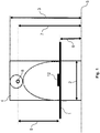
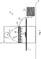
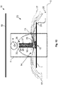
- the experimental set-up comprises an operating table 1 on which a board with a board width 2 of 0.5 m and a board height 3 of 2 m is arranged laterally.
- This board is intended to simulate a surgeon 4 whose contours are applied to the board for clarity. In some of the following figures, in part only the contours of the surgeon 4 are recorded.
- the surgeon 4 stands on a bottom 5 shown in dashed lines.
- the operating table 1 is arranged above the floor 5 with a table height 6 of 1.2 m.
- the surgeon 2 is to have an inhalation opening 8 at an inhalation height 7 of 1.6 m, which simulates an oral / nasal area of the surgeon 2.
- the inhalation distance 9 of the surgeon 4 from the operating table 1 is thus 0.4 m.
- the inhalation of the surgeon 4 is measured with a laser particle monitor 10, which is connected to the inhalation opening 8 via a measuring tube 11.
- test object 12 On the operating table 1 is a test object 12 to be operated in the form of a fabric piece.
- a test object 12 for example, fresh muscle tissue of a pig can be used, which should be assumed for the present embodiment.
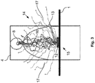
- the test object 12 can be used in one of the Fig. 3 and 4 described manner with a in Fig. 3 be indicated by an arrow indicated implement 13.
- a working device 13 a bipolar high-frequency surgical device with a power of 70 watts can be used together with a ball electrode.
- the processing of the test object 12 should be carried out standardized.
- a cut can be cut into the test object 12 with a cutting length of 5 cm and a cutting time of 5 sec.
- the surgical smoke 14 50,000,000 particles having a size equal to or more than 0.5 ⁇ m are released.
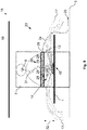
- the test object 12 and the working device 13 thus simulate a defined emission source 15 for the surgical smoke 14.
- the surgical smoke 14 spreads fan-shaped in space, in Fig. 3 it can clearly be seen how the surgical smoke 14 collects in the region of its inhalation opening 8 due to the inhalation of the surgeon 4.
- the propagating surgical smoke 14 will be distinguished into three areas. While the surgical smoke 14 propagating to the inhalation port 8 should be referred to as the hot surgical smoke 16, the (colder) laterally propagating surgical smoke 14 is intended to be a lateral surgical smoke 17 be designated.
- the Fig. 3 and 4 make it clear that the lateral surgical smoke 14 spreads on all sides.
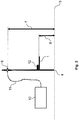
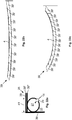
- a ventilation system 18 includes a Zu Kunststoffdecke 19 which blows against the bottom 5, not shown, a ceiling air flow 20, which presses the surgical smoke 14 away from the inhalation opening 8 against the bottom 5.
- the supply air cover 19 basically represents a pressure source, while the inhalation opening is a pressure sink, which results in the ceiling air flow 20 being at least partially neutralized in the region of the inhalation opening 8.
- the hot surgical smoke 16 experiences a significant boost over the colder room air. As in Fig. 5 to see clearly, this leads to that only the (colder) lateral surgical smoke 17 is completely pressed against the bottom 5, while the hot surgical smoke 16 is less affected by the ceiling air flow 20 and so continue to spread at least partially to the inhalation opening 8 can. This phenomenon is further enhanced by the geometry of the surgeon 4 and his (to the operating table 1 bent) working posture, which are not considered in the present embodiment due to the board-shaped design of the surgeon.
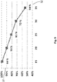
- the ceiling air flow 20 should be made as powerful as possible. This is in Fig. 6 clarified, in which the suction effect 21 in percent over the dependent on the performance of the ceiling air flow 20 volume air flow 22 of the ceiling air flow 20 in m 3 / h is applied.
- the suction effect 21 describes how many of the initially mentioned 50,000,000 particles of surgical smoke 14 emitted from the emission source 15 reach the inhalation opening 8.
- Fig. 6 98% of the particles of surgical smoke 14 expelled from the emission source 15 reach the inhalation area 8 of the surgeon 4 even at a very high volume flow 22 of 12,000 m 3 / h.
- the volume flow 22 can not be set arbitrarily high to keep this total load always below a predetermined limit.
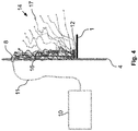
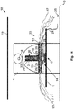
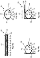
- the further pressure sink is a device 23 for the extraction of surgical smoke 14. It comprises a suction tube 24 for Provision of a negative pressure from a vacuum source 25. Further, the device 23 comprises a suction element 26 with a chamber 27, a chamber 27 opening the suction opening 28, to which the suction hose 24 for generating the negative pressure in the chamber 27 can be connected, and a plurality of the chamber 27th opening suction ports 29 for sucking at least the hot surgical smoke 16 based on the negative pressure in the chamber 27. From these suction ports 29 are in the Fig. 7 and 8th not all provided with a reference numeral for clarity. Finally, the device 23 comprises a later in Fig. 15 discussed fastener 30 for attachment of the suction element 26 on the surgeon. 4
- the hot surgical fumes 16 are sucked out via the suction openings 29 before they can reach the inhalation area 8 of the surgeon 4.
- a remainder 31 of surgical smoke 14 passing through the device 23, which nevertheless passes the proposed device 23, may optionally be accepted depending on the duration of the operation and the number of surgical operations performed to emit the surgical smoke 14.
- the experiment chamber 27 is formed of a tubular body 33 with a tube diameter of 22 mm.
- the single ones Suction openings 29 are arranged on the hose jacket over a length of 400 mm on a line and penetrate it at a distance of 4 mm, not shown.
- the indicated device 23 has a total of 95 suction openings 29.
- the individual suction openings 29 are designed for the experiment circular with a diameter of 2 mm.
- the suction openings 29 with a in Fig. 13 indicated intake angle 34 of 45 ° directed away from the operator 4 to the emission source 15.
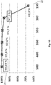
- the indicated device 23 itself is arranged in an initially variable suction height 32 above the emission source 15. For the experiment is from the Zu Kunststoffdecke 19 in Fig. 8 not shown way spent a ceiling air flow 20 of 7,500 m 3 / h.
- Fig. 9 the suction effect 21 of the specified device 23 with a constant, flowing through the suction hose 24 volume flow 22 of 330 l / min (equivalent to 19.3 m 3 / h) are considered. This is in Fig. 9 the suction effect 21 applied over the initially variable suction height 32, the in Fig. 9 in cm.
- suction effect 21 increases the closer the device 23 of the emission source 15 comes. Its maximum suction effect 21 reaches the indicated device 23 at an intake height 32 of 15 cm (corresponds to 0.15 m) above the emission source 15.
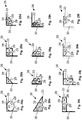
- chamber 27 and tubular body 33 are first in the Fig. 11 to 13 rather negligible. Their meaning will be discussed later in the description Fig. 14 clear.
- the individual suction hoses 24 also run half way, for example, Y-or otherwise tree-shaped into each other.
- tubular bodies 33, 33 ' can be arranged in any relative position to each other.
- the tubular bodies 33, 33 'shown are arranged parallel to one another.
- a single chamber 27 and in particular of a tubular body 33 with respect to the emission source 15 may be arbitrary. While the tubular body 33, for example Fig. 11 extends horizontally above the bottom 5, the tubular body 33 as in Fig. 12 shown, also vertically above the bottom 5 run.
- tubular body 33 in a vertical arrangement of the tubular body 33, a further tubular body 33 'can be arranged parallel to running parallel.
- a single chamber 27 may, as in Fig. 14 also be formed from a plurality of, in particular angularly arranged tubular bodies 33, 33 '. These tubular bodies 33, 33 'are then connected to one another, so that if necessary only a single suction hose 24 is necessary in order to fully apply the negative pressure of the vacuum source 25 to the indicated device 23.
- An angular arrangement of the two tubular bodies relative to each other also has the advantage that the large effective area according to Fig. 11 can be combined with the long effect on the flow path of the hot surgical smoke 16 with each other.
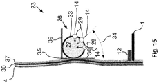
- Fig. 15 a designed as a tubular body 33 chamber 27 and its attachment to the surgeon 4 are explained in more detail using a sectional view.
- the chamber 27, which is to be assumed not to be restrictive in the following from a single tubular body 33, can be fastened to the surgeon 4 via the fastening element 30.
- the fastening element 30 can basically be constructed as desired. Depending on the application, this has been demonstrated in the experiments carried out shown that a self-adhesive fastener 30 in the form of a plastic strip with a self-adhesive surface is most useful. Depending on how and where the specified device 23 is to be attached to the surgeon 4, however, the fastening element 30 can also realize other attachment mechanisms.
- the fastening element 30 secures the tubular body 33 in a fastening plane 35.
- the individual suction openings 29, as already mentioned can enter the chamber 27 formed by the tubular body 33 with an arbitrary suction angle 34, which leads to different directions of flow for the surgical smoke 14 leads into the chamber 27.
- These inflow directions are in Fig. 15 represented by an arrow and provided for clarity with the reference numeral for the surgical smoke 14.
- the surgeon 4 wears a garment 36, such as a sterile protective apron.
- a garment 36 such as a sterile protective apron.
- the surface structure of the garment 36 also has an influence on the suction effect 21. If the garment 36 material had a rough surface, such as terry or cotton-polyester blends, the wicking effect 21 was up to 43% lower than a smooth surface, propylene or plain paper.
- an optional additional support member 37 is proposed in the present embodiment, which is placed on the garment 36. It can smooth an optionally present rough surface of the garment 36 and thus further increase the suction effect 21.
- a material for this support member 37 is particularly suitable a plastic film.
- the support element 37 should extend as completely as possible over the flow path of the surgical smoke 14 between the emission source 15 and the inhalation opening 8. Therefore, the support member 37 should be designed so that it is at least from the emission source 15 to a in Fig. 16 indicated shoulder portion 38 of the surgeon 4 extends.
- This covering element is a flow obstacle for the flowing surgical smoke 14 in the region of the chamber 27 and leads to a turbulent flow. In this way, the flowing surgical smoke 14 is slowed down in the region of the chamber 27, whereby it can reach the suction openings 29 more effectively.
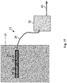
- the entire specified device 23 is supported on the support member 37 in Fig. 17 shown.
- the vacuum source 25 can be constructed arbitrarily. It may include a filter (not shown) for separating the surgical smoke. Furthermore, the vacuum source 25 may include a pump not shown for generating the negative pressure. The extracted to generate the negative pressure air can finally be discharged via an exhaust duct 40.
- the suction member 26 is shown in the configuration as used for the above experiments, ie, the chamber 27 of the suction member 26 is constituted by a tubular body 33 having a circular cross section.
- the tubular body 33 has a body length 41 of 400 mm and a body diameter 42 of 22 mm, which corresponds to a pipe surface of 380 mm 2 .
- On the lateral surface of the tubular body 33 is axially extending a series of 95 equidistantly arranged to each other suction openings 29 at a distance of 4 mm from each other.
- the individual intake openings 29 are shown with a quadrangular cross-section.
- a circular cross section, each with a diameter of 2 mm was used for the suction openings 29. In this way, a total area of all suction openings of about 295 mm 2 resulted.
- the suction openings 29 can be arranged with an arbitrary intake angle 34 to the mounting plane 35. It is also possible to arrange the intake openings 29 in multiple rows in different intake angles 34. Furthermore, it is possible to arrange the intake openings 34 distributed over different intake angles 34.
- the fastener 30 may, as in in the Figs. 18B and 18C shown to be designed arbitrarily large. The larger the fastening element 30, the more secure is the grip of the tubular body 33 on the surgeon 4.
- the cover 39 may be constructed in several parts, whereupon in Figs. 21A to 22C will be discussed in more detail later.
- the individual cover element parts 39 ', 39 "of the multi-part cover element 39 can, as in Fig. 18D shown to be arranged in different levels.
- the suction openings 29 can also be arranged in the circumferential direction of the tubular body 33 (as in FIG Fig. 19B shown) or in the axial direction of the tubular body 33 (as in FIG Fig. 19C shown) formed slit-shaped. It can also serve as a suction port 29, a single continuous slot, as in Fig. 19D shown to be arranged. Furthermore, it is also possible, as in Fig. 19E shown to choose an elliptical cross section for the suction openings 29.
- the tubular body 33 is constructed in one piece with a circular cross-section.
- the tubular body 33 can also be constructed in several pieces, wherein the cover element 39 and / or the fastening element 30 can limit the tubular body 33. It can be different in the Figs. 20B to 20L Shown cross sections are formed.
- the cover 39 and the fastener 30 can be made in one piece.
- such a multi-part cover 39 is extremely flexible and adapts itself to highly variable body shapes of the surgeon 4.
Landscapes
- Surgical Instruments (AREA)
Claims (16)
- Dispositif (23) pour extraire la fumée chirurgicale (14) ou émission de particules et/ou de gaz entre une source d'émission (15) dans la région frontale d'un chirurgien (4) et la région de sa bouche et de son nez (8), comprenant :- un tuyau d'aspiration (24) pour créer une pression négative à partir d'une source de vide (25), et- un élément d'aspiration (26) comportant- une chambre (27) formée par au moins un corps tubulaire (33) ayant une surface de section transversale de tube,- une ouverture d'aspiration (28) qui s'ouvre sur la chambre (27) et à laquelle peut être connecté le tuyau d'aspiration (24) pour générer la pression négative dans la chambre (27), et- une pluralité d'orifices d'admission (29) s'ouvrant dans la chambre (27) et traversant la paroi du corps tubulaire (33) pour aspirer la fumée chirurgicale (14) par l'effet de la pression négative dans la chambre (27),caractérisé en ce que
chaque orifice d'admission (29) a une surface de section transversale d'ouverture, et dans lequel la somme de toutes les surfaces de section transversale d'ouverture est plus petite que 2.5 fois la surface de section transversale de tube. - Dispositif (23) selon la revendication 1, dans lequel la somme de toutes les surfaces de section transversale d'ouverture est choisie dans une plage comprise entre 0.5 fois et 2.5 fois la surface de section transversale de tube.
- Dispositif (23) selon la revendication 1 ou la revendication 2, dans lequel chaque surface de section transversale est plus petite que 10 % de la somme de toutes les surfaces de section transversale d'ouverture.
- Dispositif (23) selon l'une quelconque des revendications précédentes, dans lequel la chambre (27) est formée d'au moins un corps tubulaire (33), dont la paroi est traversée par les orifices d'admission (29).
- Dispositif (23) selon la revendication 4, dans lequel la chambre (27) est formée par au moins un corps tubulaire supplémentaire (33'), lequel est de préférence orienté angulairement par rapport au premier corps tubulaire (33).
- Dispositif (23) selon la revendication 4 ou la revendication 5, dans lequel le corps tubulaire (33) est formé selon un profil arrondi et/ou carré.
- Dispositif (23) selon l'une quelconque des revendications précédentes, dans lequel le rapport entre les distances minimales des orifices d'admission (29) en millimètres et la surface de section transversale des orifices d'admission (29) en millimètres carrés est compris entre 1/50 et 1/200, de préférence de 1/100.
- Dispositif (23) selon l'une quelconque des revendications précédentes, comprenant un élément de fixation (30) pour fixer l'élément d'aspiration (26) sur le chirurgien (4).
- Dispositif (23) selon la revendication 8, dans lequel les orifices d'admission (29) sont solidarisés à un plan de fixation (35), dans lequel l'élément de fixation (30) est structuré pour fixer l'élément d'aspiration (26) au chirurgien (4) selon un angle (34) compris entre -90° et 90°, en particulier de 45°.
- Dispositif (23) selon la revendication 8 ou la revendication 9, dans lequel l'élément de fixation (30) est adapté pour solidariser l'élément d'aspiration (26) au chirurgien (4) de façon auto adhésive.
- Dispositif (23) selon l'une quelconque des revendications précédentes 8 à 10, dans lequel l'élément de fixation (30) comprend un corps en forme de film.
- Dispositif (23) selon l'une quelconque des revendications précédentes, dans lequel un matériau de l'élément d'aspiration (26) comprend la matière plastique et/ou l'acier inoxydable.
- Vêtement de travail pour un chirurgien (4), comprenant une pièce de vêtement (36) pour une couverture au moins partielle du chirurgien (4) et un dispositif (23) selon l'une quelconque des revendications précédentes, lequel dispositif est solidarisé à l'opérateur par son élément de fixation (30) sur l'un des côtés de la pièce de vêtement (36) visibles par le chirurgien (4).
- Vêtement de travail selon la revendication 13, comprenant un élément support (37) disposé entre l'élément de fixation (30) et la pièce de vêtement (36).
- Vêtement de travail selon la revendication 14, dans lequel l'élément support (37) est un autocollant et/ou une sangle de serrage.
- Vêtement de travail selon la revendication 14 ou la revendication 15, dans lequel l'élément support (37) s'étend depuis une zone d'épaule (38) du chirurgien (4) jusqu'à au-dessous de la source d'émission (15).
Applications Claiming Priority (1)
| Application Number | Priority Date | Filing Date | Title |
|---|---|---|---|
| DE102015101621.4A DE102015101621A1 (de) | 2015-02-04 | 2015-02-04 | Verfahren und Vorrichtung zur Absaugung von chrurgischem Rauch |
Publications (2)
| Publication Number | Publication Date |
|---|---|
| EP3069737A1 EP3069737A1 (fr) | 2016-09-21 |
| EP3069737B1 true EP3069737B1 (fr) | 2018-01-31 |
Family
ID=55532091
Family Applications (1)
| Application Number | Title | Priority Date | Filing Date |
|---|---|---|---|
| EP16154344.2A Active EP3069737B1 (fr) | 2015-02-04 | 2016-02-04 | Dispositif d'aspiration de fumees chirurgicales |
Country Status (2)
| Country | Link |
|---|---|
| EP (1) | EP3069737B1 (fr) |
| DE (1) | DE102015101621A1 (fr) |
Families Citing this family (1)
| Publication number | Priority date | Publication date | Assignee | Title |
|---|---|---|---|---|
| KR102479208B1 (ko) | 2017-10-24 | 2022-12-19 | 버팔로 필터 엘엘씨 | 필터링 장치 및 방법(method and apparatus for filtering) |
Family Cites Families (8)
| Publication number | Priority date | Publication date | Assignee | Title |
|---|---|---|---|---|
| US4865049A (en) * | 1988-03-21 | 1989-09-12 | Gatti John E | Smoke eliminating shield for electrocautery surgery |
| US5322521A (en) * | 1990-05-30 | 1994-06-21 | Wilk Peter J | Plume evacuation method |
| US5192276A (en) * | 1990-12-14 | 1993-03-09 | Gatti John E | Smoke aspirating device |
| US5431650A (en) | 1992-12-11 | 1995-07-11 | Cosmescu; Ioan | Vortex hand piece shroud for automatic smoke evacuator system for a surgical laser apparatus and method therefor |
| US6663610B1 (en) * | 1998-04-17 | 2003-12-16 | Leonard S. Schultz, M.D. | Smoke evacuation system |
| US7488315B2 (en) * | 2003-09-05 | 2009-02-10 | Medical Designs, Llc | Surgical smoke field evacuators |
| US7252089B1 (en) * | 2005-10-17 | 2007-08-07 | Bernardo Birnbaum | Surgical laminar air flow apparatus and method |
| US8057470B2 (en) | 2007-08-30 | 2011-11-15 | Conmed Corporation | Integrated smoke evacuation electrosurgical pencil and method |
-
2015
- 2015-02-04 DE DE102015101621.4A patent/DE102015101621A1/de not_active Withdrawn
-
2016
- 2016-02-04 EP EP16154344.2A patent/EP3069737B1/fr active Active
Also Published As
| Publication number | Publication date |
|---|---|
| EP3069737A1 (fr) | 2016-09-21 |
| DE102015101621A1 (de) | 2016-08-04 |
Similar Documents
| Publication | Publication Date | Title |
|---|---|---|
| DE69209813T2 (de) | Absaugrohr zur Verwendung bei chirurgischen Eingriffen | |
| EP3457047B1 (fr) | Dispositif de purification d'air personnalisé | |
| EP3915514B1 (fr) | Dispositif d'aspiration à manche pour une unité de traitement dentaire ainsi que dispositif d'aspiration doté d'un dispositif d'aspiration à manche | |
| DE60208174T2 (de) | Luftreinigungsvorrichtung und verfahren zur anordnung der luftreinigungsvorrichtung in empfindlichen umgebungen | |
| DE69831425T2 (de) | Rauchevakuiersystem | |
| DE69613239T2 (de) | Chirurgische rauchabzugsvorrichtung | |
| DE2228419C3 (de) | Vorrichtung für die Zuleitung eines keimfreien Luftstromes über einen Operationstisch | |
| DE2331525A1 (de) | Atemgeraet, insbesondere fuer heilzwecke | |
| EP2978457B1 (fr) | Dispositif permettant de créer une zone stérile en vue d'une intervention chirurgicale, d'examiner ou de traiter un objet, en particulier une personne | |
| EP3412234A1 (fr) | Instrument comprenant une tête multi-instruments électriques pour la coagulation plasma d'argon | |
| EP3799563B1 (fr) | Embout pour un dispositif de génération d'un flux d'air dans le conduit auditif externe | |
| EP3041526A1 (fr) | Pièce à main pour le nettoyage de plaies | |
| EP3069737B1 (fr) | Dispositif d'aspiration de fumees chirurgicales | |
| EP3558409B1 (fr) | Pointe de dispositif de succion conçue pour aspirer soigneusement un liquide biologique | |
| EP1575355B1 (fr) | Piege a insectes | |
| EP3244934A1 (fr) | Système de décontamination | |
| DE102008024728A1 (de) | Beatmungsgaskonditionierungseinrichtung, Teile davon und Verfahren zur Konditionierung von Beatmungsgas | |
| DE202021001803U1 (de) | Filtereinrichtung für eine Atemschutzmaske und Atemschutzmaske | |
| EP2505216A1 (fr) | Dispositif d'aspiration d'effluents lors de l'ablation de tissus biologiques | |
| DE102020121450B4 (de) | Vorrichtung zum Schutz vor Übertragung von Krankheitserregern durch Aerosole in geschlossenen Räumen | |
| EP3799564B1 (fr) | Embout pour un dispositif de génération d'un flux d'air dans le conduit auditif externe | |
| DE102022106734A1 (de) | Ausatemsystem und Kugelgelenk für eine Patientenschnittstelle | |
| DE102016208591A1 (de) | Medizinisches Gerät mit Gaspumpvorrichtung | |
| WO2022223679A1 (fr) | Dispositif de ventilation et lit de patient | |
| DE102020127616A1 (de) | Umluft-Lüftungsvorrichtung |
Legal Events
| Date | Code | Title | Description |
|---|---|---|---|
| PUAI | Public reference made under article 153(3) epc to a published international application that has entered the european phase |
Free format text: ORIGINAL CODE: 0009012 |
|
| AK | Designated contracting states |
Kind code of ref document: A1 Designated state(s): AL AT BE BG CH CY CZ DE DK EE ES FI FR GB GR HR HU IE IS IT LI LT LU LV MC MK MT NL NO PL PT RO RS SE SI SK SM TR |
|
| AX | Request for extension of the european patent |
Extension state: BA ME |
|
| 17P | Request for examination filed |
Effective date: 20170321 |
|
| RBV | Designated contracting states (corrected) |
Designated state(s): AL AT BE BG CH CY CZ DE DK EE ES FI FR GB GR HR HU IE IS IT LI LT LU LV MC MK MT NL NO PL PT RO RS SE SI SK SM TR |
|
| RIC1 | Information provided on ipc code assigned before grant |
Ipc: A61M 1/00 20060101AFI20170721BHEP Ipc: A61B 18/04 20060101ALN20170721BHEP Ipc: B08B 15/00 20060101ALI20170721BHEP |
|
| RIC1 | Information provided on ipc code assigned before grant |
Ipc: A61M 1/00 20060101AFI20170810BHEP Ipc: B08B 15/00 20060101ALI20170810BHEP Ipc: A61B 18/04 20060101ALN20170810BHEP |
|
| GRAP | Despatch of communication of intention to grant a patent |
Free format text: ORIGINAL CODE: EPIDOSNIGR1 |
|
| INTG | Intention to grant announced |
Effective date: 20170921 |
|
| GRAS | Grant fee paid |
Free format text: ORIGINAL CODE: EPIDOSNIGR3 |
|
| GRAA | (expected) grant |
Free format text: ORIGINAL CODE: 0009210 |
|
| AK | Designated contracting states |
Kind code of ref document: B1 Designated state(s): AL AT BE BG CH CY CZ DE DK EE ES FI FR GB GR HR HU IE IS IT LI LT LU LV MC MK MT NL NO PL PT RO RS SE SI SK SM TR |
|
| REG | Reference to a national code |
Ref country code: GB Ref legal event code: FG4D Free format text: NOT ENGLISH Ref country code: CH Ref legal event code: EP |
|
| REG | Reference to a national code |
Ref country code: AT Ref legal event code: REF Ref document number: 966779 Country of ref document: AT Kind code of ref document: T Effective date: 20180215 |
|
| REG | Reference to a national code |
Ref country code: IE Ref legal event code: FG4D Free format text: LANGUAGE OF EP DOCUMENT: GERMAN |
|
| REG | Reference to a national code |
Ref country code: DE Ref legal event code: R096 Ref document number: 502016000513 Country of ref document: DE |
|
| REG | Reference to a national code |
Ref country code: NL Ref legal event code: MP Effective date: 20180131 |
|
| REG | Reference to a national code |
Ref country code: LT Ref legal event code: MG4D |
|
| PG25 | Lapsed in a contracting state [announced via postgrant information from national office to epo] |
Ref country code: LT Free format text: LAPSE BECAUSE OF FAILURE TO SUBMIT A TRANSLATION OF THE DESCRIPTION OR TO PAY THE FEE WITHIN THE PRESCRIBED TIME-LIMIT Effective date: 20180131 Ref country code: NL Free format text: LAPSE BECAUSE OF FAILURE TO SUBMIT A TRANSLATION OF THE DESCRIPTION OR TO PAY THE FEE WITHIN THE PRESCRIBED TIME-LIMIT Effective date: 20180131 Ref country code: ES Free format text: LAPSE BECAUSE OF FAILURE TO SUBMIT A TRANSLATION OF THE DESCRIPTION OR TO PAY THE FEE WITHIN THE PRESCRIBED TIME-LIMIT Effective date: 20180131 Ref country code: HR Free format text: LAPSE BECAUSE OF FAILURE TO SUBMIT A TRANSLATION OF THE DESCRIPTION OR TO PAY THE FEE WITHIN THE PRESCRIBED TIME-LIMIT Effective date: 20180131 Ref country code: NO Free format text: LAPSE BECAUSE OF FAILURE TO SUBMIT A TRANSLATION OF THE DESCRIPTION OR TO PAY THE FEE WITHIN THE PRESCRIBED TIME-LIMIT Effective date: 20180430 Ref country code: FI Free format text: LAPSE BECAUSE OF FAILURE TO SUBMIT A TRANSLATION OF THE DESCRIPTION OR TO PAY THE FEE WITHIN THE PRESCRIBED TIME-LIMIT Effective date: 20180131 |
|
| PG25 | Lapsed in a contracting state [announced via postgrant information from national office to epo] |
Ref country code: SE Free format text: LAPSE BECAUSE OF FAILURE TO SUBMIT A TRANSLATION OF THE DESCRIPTION OR TO PAY THE FEE WITHIN THE PRESCRIBED TIME-LIMIT Effective date: 20180131 Ref country code: LV Free format text: LAPSE BECAUSE OF FAILURE TO SUBMIT A TRANSLATION OF THE DESCRIPTION OR TO PAY THE FEE WITHIN THE PRESCRIBED TIME-LIMIT Effective date: 20180131 Ref country code: RS Free format text: LAPSE BECAUSE OF FAILURE TO SUBMIT A TRANSLATION OF THE DESCRIPTION OR TO PAY THE FEE WITHIN THE PRESCRIBED TIME-LIMIT Effective date: 20180131 Ref country code: GR Free format text: LAPSE BECAUSE OF FAILURE TO SUBMIT A TRANSLATION OF THE DESCRIPTION OR TO PAY THE FEE WITHIN THE PRESCRIBED TIME-LIMIT Effective date: 20180501 Ref country code: BG Free format text: LAPSE BECAUSE OF FAILURE TO SUBMIT A TRANSLATION OF THE DESCRIPTION OR TO PAY THE FEE WITHIN THE PRESCRIBED TIME-LIMIT Effective date: 20180430 Ref country code: PL Free format text: LAPSE BECAUSE OF FAILURE TO SUBMIT A TRANSLATION OF THE DESCRIPTION OR TO PAY THE FEE WITHIN THE PRESCRIBED TIME-LIMIT Effective date: 20180131 Ref country code: IS Free format text: LAPSE BECAUSE OF FAILURE TO SUBMIT A TRANSLATION OF THE DESCRIPTION OR TO PAY THE FEE WITHIN THE PRESCRIBED TIME-LIMIT Effective date: 20180531 |
|
| PG25 | Lapsed in a contracting state [announced via postgrant information from national office to epo] |
Ref country code: MT Free format text: LAPSE BECAUSE OF FAILURE TO SUBMIT A TRANSLATION OF THE DESCRIPTION OR TO PAY THE FEE WITHIN THE PRESCRIBED TIME-LIMIT Effective date: 20180131 |
|
| PG25 | Lapsed in a contracting state [announced via postgrant information from national office to epo] |
Ref country code: AL Free format text: LAPSE BECAUSE OF FAILURE TO SUBMIT A TRANSLATION OF THE DESCRIPTION OR TO PAY THE FEE WITHIN THE PRESCRIBED TIME-LIMIT Effective date: 20180131 Ref country code: IT Free format text: LAPSE BECAUSE OF FAILURE TO SUBMIT A TRANSLATION OF THE DESCRIPTION OR TO PAY THE FEE WITHIN THE PRESCRIBED TIME-LIMIT Effective date: 20180131 Ref country code: EE Free format text: LAPSE BECAUSE OF FAILURE TO SUBMIT A TRANSLATION OF THE DESCRIPTION OR TO PAY THE FEE WITHIN THE PRESCRIBED TIME-LIMIT Effective date: 20180131 Ref country code: RO Free format text: LAPSE BECAUSE OF FAILURE TO SUBMIT A TRANSLATION OF THE DESCRIPTION OR TO PAY THE FEE WITHIN THE PRESCRIBED TIME-LIMIT Effective date: 20180131 |
|
| REG | Reference to a national code |
Ref country code: DE Ref legal event code: R097 Ref document number: 502016000513 Country of ref document: DE |
|
| REG | Reference to a national code |
Ref country code: BE Ref legal event code: MM Effective date: 20180228 |
|
| PG25 | Lapsed in a contracting state [announced via postgrant information from national office to epo] |
Ref country code: SK Free format text: LAPSE BECAUSE OF FAILURE TO SUBMIT A TRANSLATION OF THE DESCRIPTION OR TO PAY THE FEE WITHIN THE PRESCRIBED TIME-LIMIT Effective date: 20180131 Ref country code: SM Free format text: LAPSE BECAUSE OF FAILURE TO SUBMIT A TRANSLATION OF THE DESCRIPTION OR TO PAY THE FEE WITHIN THE PRESCRIBED TIME-LIMIT Effective date: 20180131 Ref country code: LU Free format text: LAPSE BECAUSE OF NON-PAYMENT OF DUE FEES Effective date: 20180204 Ref country code: CZ Free format text: LAPSE BECAUSE OF FAILURE TO SUBMIT A TRANSLATION OF THE DESCRIPTION OR TO PAY THE FEE WITHIN THE PRESCRIBED TIME-LIMIT Effective date: 20180131 Ref country code: MC Free format text: LAPSE BECAUSE OF FAILURE TO SUBMIT A TRANSLATION OF THE DESCRIPTION OR TO PAY THE FEE WITHIN THE PRESCRIBED TIME-LIMIT Effective date: 20180131 Ref country code: DK Free format text: LAPSE BECAUSE OF FAILURE TO SUBMIT A TRANSLATION OF THE DESCRIPTION OR TO PAY THE FEE WITHIN THE PRESCRIBED TIME-LIMIT Effective date: 20180131 |
|
| PLBE | No opposition filed within time limit |
Free format text: ORIGINAL CODE: 0009261 |
|
| STAA | Information on the status of an ep patent application or granted ep patent |
Free format text: STATUS: NO OPPOSITION FILED WITHIN TIME LIMIT |
|
| REG | Reference to a national code |
Ref country code: IE Ref legal event code: MM4A |
|
| 26N | No opposition filed |
Effective date: 20181102 |
|
| PG25 | Lapsed in a contracting state [announced via postgrant information from national office to epo] |
Ref country code: IE Free format text: LAPSE BECAUSE OF NON-PAYMENT OF DUE FEES Effective date: 20180204 |
|
| PG25 | Lapsed in a contracting state [announced via postgrant information from national office to epo] |
Ref country code: SI Free format text: LAPSE BECAUSE OF FAILURE TO SUBMIT A TRANSLATION OF THE DESCRIPTION OR TO PAY THE FEE WITHIN THE PRESCRIBED TIME-LIMIT Effective date: 20180131 Ref country code: BE Free format text: LAPSE BECAUSE OF NON-PAYMENT OF DUE FEES Effective date: 20180228 |
|
| PG25 | Lapsed in a contracting state [announced via postgrant information from national office to epo] |
Ref country code: FR Free format text: LAPSE BECAUSE OF NON-PAYMENT OF DUE FEES Effective date: 20180331 |
|
| PG25 | Lapsed in a contracting state [announced via postgrant information from national office to epo] |
Ref country code: TR Free format text: LAPSE BECAUSE OF FAILURE TO SUBMIT A TRANSLATION OF THE DESCRIPTION OR TO PAY THE FEE WITHIN THE PRESCRIBED TIME-LIMIT Effective date: 20180131 |
|
| PG25 | Lapsed in a contracting state [announced via postgrant information from national office to epo] |
Ref country code: PT Free format text: LAPSE BECAUSE OF FAILURE TO SUBMIT A TRANSLATION OF THE DESCRIPTION OR TO PAY THE FEE WITHIN THE PRESCRIBED TIME-LIMIT Effective date: 20180131 |
|
| PG25 | Lapsed in a contracting state [announced via postgrant information from national office to epo] |
Ref country code: CY Free format text: LAPSE BECAUSE OF FAILURE TO SUBMIT A TRANSLATION OF THE DESCRIPTION OR TO PAY THE FEE WITHIN THE PRESCRIBED TIME-LIMIT Effective date: 20180131 Ref country code: MK Free format text: LAPSE BECAUSE OF NON-PAYMENT OF DUE FEES Effective date: 20180131 Ref country code: HU Free format text: LAPSE BECAUSE OF FAILURE TO SUBMIT A TRANSLATION OF THE DESCRIPTION OR TO PAY THE FEE WITHIN THE PRESCRIBED TIME-LIMIT; INVALID AB INITIO Effective date: 20160204 |
|
| GBPC | Gb: european patent ceased through non-payment of renewal fee |
Effective date: 20200204 |
|
| PG25 | Lapsed in a contracting state [announced via postgrant information from national office to epo] |
Ref country code: GB Free format text: LAPSE BECAUSE OF NON-PAYMENT OF DUE FEES Effective date: 20200204 |
|
| PGFP | Annual fee paid to national office [announced via postgrant information from national office to epo] |
Ref country code: CH Payment date: 20220222 Year of fee payment: 7 Ref country code: AT Payment date: 20220131 Year of fee payment: 7 |
|
| REG | Reference to a national code |
Ref country code: CH Ref legal event code: PL |
|
| REG | Reference to a national code |
Ref country code: AT Ref legal event code: MM01 Ref document number: 966779 Country of ref document: AT Kind code of ref document: T Effective date: 20230204 |
|
| PG25 | Lapsed in a contracting state [announced via postgrant information from national office to epo] |
Ref country code: LI Free format text: LAPSE BECAUSE OF NON-PAYMENT OF DUE FEES Effective date: 20230228 Ref country code: CH Free format text: LAPSE BECAUSE OF NON-PAYMENT OF DUE FEES Effective date: 20230228 Ref country code: AT Free format text: LAPSE BECAUSE OF NON-PAYMENT OF DUE FEES Effective date: 20230204 |
|
| P01 | Opt-out of the competence of the unified patent court (upc) registered |
Effective date: 20231128 |
|
| PGFP | Annual fee paid to national office [announced via postgrant information from national office to epo] |
Ref country code: DE Payment date: 20250224 Year of fee payment: 10 |