EP3069601B1 - Schutzvorrichtung für zierpflanzen im aussenbereich oder anderes material - Google Patents
Schutzvorrichtung für zierpflanzen im aussenbereich oder anderes material Download PDFInfo
- Publication number
- EP3069601B1 EP3069601B1 EP16160528.2A EP16160528A EP3069601B1 EP 3069601 B1 EP3069601 B1 EP 3069601B1 EP 16160528 A EP16160528 A EP 16160528A EP 3069601 B1 EP3069601 B1 EP 3069601B1
- Authority
- EP
- European Patent Office
- Prior art keywords
- component
- protection device
- fixing
- slots
- protection
- Prior art date
- Legal status (The legal status is an assumption and is not a legal conclusion. Google has not performed a legal analysis and makes no representation as to the accuracy of the status listed.)
- Active
Links
Images
Classifications
-
- A—HUMAN NECESSITIES
- A01—AGRICULTURE; FORESTRY; ANIMAL HUSBANDRY; HUNTING; TRAPPING; FISHING
- A01G—HORTICULTURE; CULTIVATION OF VEGETABLES, FLOWERS, RICE, FRUIT, VINES, HOPS OR SEAWEED; FORESTRY; WATERING
- A01G13/00—Protection of plants
- A01G13/20—Protective coverings for plants
- A01G13/21—Protective coverings for plants providing overhead protection, i.e. canopies
- A01G13/22—Protective coverings for plants providing overhead protection, i.e. canopies for individual plants
Definitions
- the present invention relates to a protection device for protecting outdoor ornamental plants or another material from inclement weather or also from direct sunlight.
- the protection device according to the invention is intended both for protecting ornamental pot plants located in pot holders located outside on the balconies of houses or any other material positioned close to vertical surfaces.
- DE 88 09 301 U1 discloses a protection device for outdoor ornamental plants, or other material, comprising a protection element, suitable for protecting said ornamental plants, or said other material, from the atmospheric agents and from direct sunlight, bearing elements for supporting said protection element and fixing elements for fixing said bearing elements to a supporting element, wherein each bearing element comprises a first component, a first end of which may be removably coupled with a respective fixing element.
- Object of the present invention is to provide a protection device for protecting outdoor ornamental plants, or another material, from inclement weather or also from direct sunlight, that is fixable simply and securely, is easy to fit and is versatile, so as to be adapted easily to the needs of those who use it.
- the object of the invention is achieved with a protection device according to claim 1.
- Owing to the invention it is possible to make a protection device for protecting outdoor ornamental plants, or another material, that is easy to make, easy to install and easily adaptable to different configurations and dimensions of an area to be protected in which the material to be protected is arranged, for example outdoor ornamental plants inserted into a container fixed to the railing of a balcony.
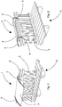
- a protection device 1 according to the invention is illustrated, which is fixed to the railing 3 of a balcony 2 so as to cover and protect a receptacle 7, which is also fixed to the railing 3, in which vases of ornamental plants can be housed.
- the protection device 1 comprises a protection sheet 4 that can be made, for example, of cloth or plastics, or of any other material that is suitable for withstanding inclement weather such as rain, snow, or hail.
- the protection sheet 4 having for example a substantially rectangular shape is fixed, along a pair of opposite sides, to two bearing elements 5 which are in turn fixed to the railing 3 of the balcony 2 by a respective fixing element 6.
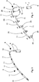
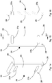
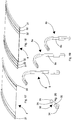
- Each supporting element 5 consists of a first component 8, by means of which the supporting element is fixed to the railing 3 of the balcony 2, and of at least one second component 11 that is fixable to the first component 8 and constitutes a lengthening of the first component 8.
- the supporting element 5 can comprise a plurality of second components 11, fixed together and to the first component 8, which are variable in number, each of which constitutes a further lenghtening of the first component 8, to adapt the length of the supporting element 5 to the dimensions of the zone to be protected.
- the first component 8 comprises a substantially rectilinear first part 9 and a curvilinear second part 10, integral with the first part 9 and having an arc shape.
- the first part 9 is provided with a first end 12 intended for being coupled with the fixing element 6, so as to be able to be fixed to the railing 3, whereas the second part 10 is provided with a fork-shaped second end 13 intended for being coupled with a second component 11.
- the second end 13 is provided with through holes 14 that are intended for receiving fixing elements 20 ( Figure 4 ), for example screws, bolts, or joint rivets, for fixing the first component 8 to a second component 11.
- the through holes 14 can be threaded.
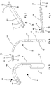
- the second component 11 is provided with a first fork-shaped end 16 and with a second end 17 having a flattened shape, having a shape and dimensions that are such as to be able to be inserted into the first fork-shaped end 16 of another second component 11, or into the second fork-shaped end 13 of the first component 8.
- the first end 16 is provided with further through holes 18 intended for receiving the fixing elements20, for fixing the second component 11 to another second component 11.
- the second end 17 is provided with still further through holes 19 intended for receiving the fixing elements20, for fixing the second component 11 to another second component 11, or to the first component 8.
- the further through holes 18 and the still further through holes 19 can be threaded.
- a protection accessory 32 is associable ( Figure 20 ) consisting of a flattened body 33 with a rounded end 34.
- the flattened body 33 has a shape and dimensions that are such as to be able to be inserted into the first fork-shaped end 16 of the second component 11.
- the flattened body 33 is further provided with other through holes 35 intended for receiving the fixing elements 20 for fixing the protection accessory 32 to the second component 11.
- the protection accessory 32 is used to cover sharp corners of the fork-shaped first end 16 of the second component 11, to prevent the sharp corners being able to harm persons or damage objects that accidentally knock against the free end of the supporting element 5.
- connection between the first component 8, the second component 11, and between the second components 11 rather than being made with the fixing elements 20, can also be made as a joint, for example with dovetail joints, by suitably configuring the second end 13 of the first component 8 and the first end 16 e the second end 17 of the second component 11.
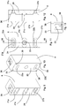
- the fixing element 6 is illustrated by means of which the bearing elements 5 can be fixed to the railing 3 of a balcony 2 or to a wall.
- the fixing element 6 has a substantially parallelepiped shape and is provided with a longitudinal cavity 36 having a shape and dimensions such as to be able to couple with the first end 12 of the first component 8 of the supporting element 5. Further, the cross section of the longitudinal cavity 36 and of the first end 12 of the first component 8 of the supporting element 5 can be chosen in such a manner as to enable the first end 12 to be inserted into the fixing element 6 in two different positions rotated by 180° to one another. For example, both the longitudinal cavity 36, and the first end 12 can have a rectangular cross section.
- a locking element 23 is arranged, consisting for example of a retractable ball, intended for locking said first end 12 in the longitudinal cavity 36, by being inserted into a transverse hole 15 ( Figures 5 and 6 ) of said first end 12.
- a spacer element 26 is illustrated that is associable with the fixing element 6, to space the fixing element 6 away from the railing 3, to adapt the protection device 1 according to the invention better to the type of balcony and to the type of railing to which the device is fixed.
- the spacer element 26 has a parallelepiped shape and is provided, on one face 29 thereof, with four protuberances 28, each of which is arranged near a vertex of the face 29.
- the protuberances 28 are intended for pressure coupling with corresponding recesses 30 made near the vertices of the first face 25 of the fixing element 6, for fixing the spacer element 26 to the fixing element 6.
- the spacer element 26 is provided with a pair of further slots 27a and 27b, which, when the spacer element 26 is coupled with the fixing element 6, are aligned with the slots 22a and 22b of the fixing element, respectively.
- the further slots 27a and 27b are used for the passage of the fixing means that is used for connecting the fixing element 6 to the railing 3, or to a wall.
- All the components of the supporting element 5, the fixing element 6 and the spacer element 26 can be made of any suitable material, for example they can be made of metal, plastics, recycled PVC, wood, etc.
- FIG 17 a first embodiment is illustrated of the protection sheet 4 that is provided on two opposite edges with respective tubular slots 31 that can be inserted into the bearing elements 5 to anchor the protection sheet to the bearing elements.
- the tubular slots 31 can be made in various modes, for example by folding on the sheet 4 the aforesaid opposite edges and fixing the opposite edges to the rest of the sheet by sewing, or by fixing strips of Velcro to the edges and to the sheet 4, such that it is possible to fix the folded edge by said strips of Velcro.
- FIG 18 another embodiment of the sheet 4 is shown, in which the sheet is provided with a plurality of further tubular slots 32 parallel to the tubular slots 31 and made, for example, by a plurality of parallel seams.
- the further tubular slots 32 can also be distributed over the entire surface of the sheet 4, making the sheet with a double layer of material and obtaining the tubular slots 31 and the further tubular slots 32 by a series of seams that are parallel to one another.
- Figure 19 illustrates three embodiments 8, 8a, and 8b of the first part of the supporting element 5.
- the three embodiments differ from one another by the different length of the first component 9, 9a, 9b, which enables the protection device 1 according to the invention to be adapted to the shape and dimensions of the zone to be protected.
Landscapes
- Health & Medical Sciences (AREA)
- General Health & Medical Sciences (AREA)
- Toxicology (AREA)
- Life Sciences & Earth Sciences (AREA)
- Environmental Sciences (AREA)
- Steps, Ramps, And Handrails (AREA)
Claims (14)
- Schutzvorrichtung (1) für dekorative Außenpflanzen oder ein anderes Material, mit einem Schutzelement (4), das geeignet ist, die dekorativen Pflanzen oder das andere Material gegenüber atmosphärischen Bestandteilen und gegenüber direktem Sonnenlicht zu schützen, und das Tragelemente (5) aufweist, um die Fixierelemente (6) zur Aufnahme des Schutzelementes (4) zu tragen, um die Trageelemente an einem Aufnahmeelement zu fixieren, wobei jedes Trageelement (5) eine erste Komponente (8) aufweist, von der ein erstes Ende (12) lösbar mit einem betreffenden Fixierelement (6) gekoppelt ist, und mit wenigstens einer zweiten Komponente (11), die an einem zweiten Ende (13) der ersten Komponente (8) befestigt werden kann, wobei die wenigstens eine zweite Komponente (11) eine Verlängerung der ersten Komponente (8) bildet, dadurch gekennzeichnet, dass die erste Komponente (8) einen im Wesentlichen rechteckförmigen ersten Teil (9) und ein gekrümmtes zweites Teil (10) aufweist, wobei das erste Teil (9) das erste Ende (12) aufweist, und wobei das zweite Teil (10) das zweite Ende (13) aufweist.
- Schutzvorrichtung (1) nach Anspruch 1, dadurch gekennzeichnet, dass sie eine Mehrzahl von zweiten Komponenten (11) aufweist, die miteinander und mit der ersten Komponente (8) verbunden sein können.
- Schutzvorrichtung (1) nach Anspruch 1 oder 2, bei der das zweite Ende (13) der ersten Komponente (8) gabelförmig ist und mit Durchgangslöchern (14) versehen ist, die geeignet sind, um Fixierelemente (20) aufzunehmen.
- Schutzvorrichtung (1) nach Anspruch 3, bei der die wenigstens eine zweite Komponente (11) mit einem ersten Ende (16) versehen ist, die eine Gabelform aufweist und mit einem zweiten Ende (17), das eine abgeflachte Form aufweist, wobei das zweite Ende (17) eine derartige Form und Größe aufweist, dass es in das zweite gabelförmige Ende (13) der ersten Komponente (8) oder in das erste gabelförmige Ende (16) der anderen zweiten Komponente (11) eingeführt werden kann.
- Schutzvorrichtung (1) nach Anspruch 4, bei der das erste Ende (16) der wenigstens einen zweiten Komponente (11) mit weiteren Durchgangslöchern (18) versehen ist, die dazu vorgesehen sind, die Fixierelemente (20) aufzunehmen, um die wenigstens eine zweite Komponente (11) an einer anderen zweiten Komponente (11) zu fixieren, und wobei das zweite Ende (17) der wenigstens einen zweiten Komponente (11) mit weiteren Durchgangslöchern (19) versehen ist, die dazu ausgebildet sind, die Fixierelemente (20) aufzunehmen, um die wenigstens eine zweite Komponente (11) an einer anderen zweiten Komponente (11) oder an der ersten Komponente (8) zu fixieren.
- Schutzvorrichtung (1) nach irgendeinem vorhergehenden Anspruch, bei der das Fixierelement (6) eine im Wesentlichen parallelepipedische Form aufweist und mit einem längsseitigen Hohlraum (36) versehen ist, der eine Form und Größe aufweist, derart, dass eine Kopplung mit dem ersten Ende (12) der ersten Komponente (8) des Trageelementes (5) ermöglicht ist.
- Schutzvorrichtung (1) nach Anspruch 6, wobei innerhalb des längsseitigen Hohlraums (36) ein Verriegelungselement (23) vorgesehen ist, das geeignet ist, das erste Ende (12) in dem längsseitigen Hohlraum (36) lösbar zu verriegeln, wobei das Verriegelungselement (23) in ein Querloch (15) des ersten Endes (12) einführbar ist.
- Schutzvorrichtung (1) nach Anspruch 7, bei der an einer ersten Fläche (25) des Fixierelementes (6) zwei Schlitze (22a und 22b) ausgebildet sind, wobei an einer zweiten Fläche (24) gegenüber der ersten Fläche (25) drei Fenster (21a, 21b, 21c) gebildet sind, von denen zwei (21a und 21b) gegenüber den korrespondierenden Schlitzen (22a und 22b) angeordnet sind, und wobei ein drittes Fenster (21c) gegenüber dem Verriegelungselement (23) angeordnet ist.
- Schutzvorrichtung (1) nach Anspruch 8, die ferner ein Abstandselement (26) aufweist, das mit dem Fixierelement (6) koppelbar ist, das eine parallelepipedische Form aufweist und an einer seiner Flächen (29) mit vier Ausstülpungen (28) versehen ist, von denen jede in der Nähe eines Scheitels der Fläche (29) angeordnet ist, wobei die Ausstülpungen (28) dazu ausgebildet sind, eine Druckkopplung mit zugeordneten Vertiefungen (30) zu bewirken, die in der Nähe der Scheitel der ersten Fläche (25) des Fixierelementes (6) vorgesehen sind.
- Schutzvorrichtung (1) nach Anspruch 9, bei der das Abstandselement (26) mit einem Paar von weiteren Schlitzen (27a und 27b) vorgesehen ist, derart, dass diese dann, wenn das Abstandselement (26) mit dem Fixierelement (6) gekoppelt ist, mit den Schlitzen (22a bzw. 22b) des Fixierelementes (6) ausgerichtet ist.
- Schutzvorrichtung (1) nach irgendeinem vorhergehenden Anspruch, bei dem das Schutzelement (4) die Form einer Platte aufweist und an zwei gegenüberliegenden Seiten mit betreffenden rohrförmigen Schlitzen (31) versehen ist, die zur Einführung an betreffenden Trageelementen (5) geeignet sind.
- Schutzvorrichtung (1) nach Anspruch 12, bei der jeder rohrförmige Schlitz (31) wenigstens einem weiteren rohrförmigen Schlitz (32) zugeordnet ist, der parallel zu dem rohrförmigen Schlitz (31) ist.
- Schutzvorrichtung (1) nach Anspruch 12, mit einer Mehrzahl von weiteren rohrförmigen Schlitzen (32), die zueinander parallel sind und parallel zu den rohrförmigen Schlitzen (31) sind, wobei die weiteren rohrförmigen Schlitze (32) über die gesamte Oberfläche des Schutzelementes (4) verteilt sind.
- Schutzvorrichtung (1) nach irgendeinem vorhergehenden Anspruch, ferner umfassend ein Schutzzusatzteil (32), das mit einem abgeflachten Körper (33) mit einem gerundeten Ende (34) versehen ist, wobei der abgeflachte Körper (33) eine Form und Größe aufweist, derart, dass er in das erste gabelförmige Ende (16) einer zweiten Komponente (11) eingeführt werden kann.
Priority Applications (1)
| Application Number | Priority Date | Filing Date | Title |
|---|---|---|---|
| SI201630097T SI3069601T1 (sl) | 2015-03-18 | 2016-03-15 | Zaščitna naprava za zunanje okrasne rastline ali drug material |
Applications Claiming Priority (1)
| Application Number | Priority Date | Filing Date | Title |
|---|---|---|---|
| ITMO20150061 | 2015-03-18 |
Publications (3)
| Publication Number | Publication Date |
|---|---|
| EP3069601A1 EP3069601A1 (de) | 2016-09-21 |
| EP3069601B1 true EP3069601B1 (de) | 2018-08-15 |
| EP3069601B8 EP3069601B8 (de) | 2018-10-17 |
Family
ID=53177805
Family Applications (1)
| Application Number | Title | Priority Date | Filing Date |
|---|---|---|---|
| EP16160528.2A Active EP3069601B8 (de) | 2015-03-18 | 2016-03-15 | Schutzvorrichtung für zierpflanzen im aussenbereich oder anderes material |
Country Status (2)
| Country | Link |
|---|---|
| EP (1) | EP3069601B8 (de) |
| SI (1) | SI3069601T1 (de) |
Family Cites Families (4)
| Publication number | Priority date | Publication date | Assignee | Title |
|---|---|---|---|---|
| FR1178331A (fr) * | 1957-07-09 | 1959-05-06 | Dispositif protecteur des cultures contre les intempéries hivernales ou printanières et notamment contre la gelée | |
| AT387304B (de) * | 1987-07-28 | 1989-01-10 | Hehle Heribert Ing | Einrichtung zum abdecken von im freien stehenden und in pflanzbehaeltern gesetzten blumenschmuck |
| DE29513171U1 (de) * | 1995-08-16 | 1995-10-19 | Ing. Gerhard Beckmann Kg, 88239 Wangen | Pflanzenüberdachung |
| DE20106237U1 (de) * | 2001-04-10 | 2001-06-21 | Ing. G. Beckmann KG, 88239 Wangen | Schutzdach |
-
2016
- 2016-03-15 EP EP16160528.2A patent/EP3069601B8/de active Active
- 2016-03-15 SI SI201630097T patent/SI3069601T1/sl unknown
Non-Patent Citations (1)
| Title |
|---|
| None * |
Also Published As
| Publication number | Publication date |
|---|---|
| EP3069601A1 (de) | 2016-09-21 |
| EP3069601B8 (de) | 2018-10-17 |
| SI3069601T1 (sl) | 2019-01-31 |
Similar Documents
| Publication | Publication Date | Title |
|---|---|---|
| USD874280S1 (en) | Hinged u-block for packaging | |
| USD780893S1 (en) | Universal downspout adapter | |
| USD872894S1 (en) | Lineal for panel attachment over a window | |
| USD1086972S1 (en) | Folding kitchen for vehicle canopy | |
| USD787403S1 (en) | Foldable surface protector | |
| US20120240970A1 (en) | Portable shelter | |
| USD874619S1 (en) | Fitting | |
| USD923276S1 (en) | Trolley | |
| USD567123S1 (en) | Remote visual inspection device | |
| USD839430S1 (en) | Portable x-ray device | |
| USD928531S1 (en) | Interconnecting panel element | |
| USD640798S1 (en) | Portable and expandable protected garden building | |
| USD884186S1 (en) | Portable X-ray device | |
| US9528288B2 (en) | Multiple orientation pool skimming net with three-point leveraging configurations | |
| EP3069601A1 (de) | Schutzvorrichtung für zierpflanzen im aussenbereich oder anderes material | |
| USD995601S1 (en) | Smart camera | |
| USD837992S1 (en) | Spa with integrated table | |
| USD782625S1 (en) | Rain chain component | |
| US9717361B2 (en) | Spring-loaded adjustable window rack | |
| US9445548B1 (en) | Saddle mounting assembly for a grave marker | |
| USD849605S1 (en) | Field stretcher | |
| US9277807B2 (en) | Tree stand table device | |
| KR200471065Y1 (ko) | 가변 타프 | |
| US9474401B2 (en) | Spring-loaded adjustable window rack | |
| US8959711B1 (en) | Door stop device |
Legal Events
| Date | Code | Title | Description |
|---|---|---|---|
| PUAI | Public reference made under article 153(3) epc to a published international application that has entered the european phase |
Free format text: ORIGINAL CODE: 0009012 |
|
| AK | Designated contracting states |
Kind code of ref document: A1 Designated state(s): AL AT BE BG CH CY CZ DE DK EE ES FI FR GB GR HR HU IE IS IT LI LT LU LV MC MK MT NL NO PL PT RO RS SE SI SK SM TR |
|
| AX | Request for extension of the european patent |
Extension state: BA ME |
|
| RAP1 | Party data changed (applicant data changed or rights of an application transferred) |
Owner name: DELLADIO, MAURO Owner name: DELLADIO, RICCARDO Owner name: DELLADIO, FABRIZIO |
|
| RIN1 | Information on inventor provided before grant (corrected) |
Inventor name: DELLADIO, FABRIZIO Inventor name: DELLADIO, RICCARDO Inventor name: DELLADIO, MAURO |
|
| STAA | Information on the status of an ep patent application or granted ep patent |
Free format text: STATUS: REQUEST FOR EXAMINATION WAS MADE |
|
| 17P | Request for examination filed |
Effective date: 20170321 |
|
| RBV | Designated contracting states (corrected) |
Designated state(s): AL AT BE BG CH CY CZ DE DK EE ES FI FR GB GR HR HU IE IS IT LI LT LU LV MC MK MT NL NO PL PT RO RS SE SI SK SM TR |
|
| GRAP | Despatch of communication of intention to grant a patent |
Free format text: ORIGINAL CODE: EPIDOSNIGR1 |
|
| STAA | Information on the status of an ep patent application or granted ep patent |
Free format text: STATUS: GRANT OF PATENT IS INTENDED |
|
| INTG | Intention to grant announced |
Effective date: 20180321 |
|
| GRAS | Grant fee paid |
Free format text: ORIGINAL CODE: EPIDOSNIGR3 |
|
| GRAA | (expected) grant |
Free format text: ORIGINAL CODE: 0009210 |
|
| STAA | Information on the status of an ep patent application or granted ep patent |
Free format text: STATUS: THE PATENT HAS BEEN GRANTED |
|
| AK | Designated contracting states |
Kind code of ref document: B1 Designated state(s): AL AT BE BG CH CY CZ DE DK EE ES FI FR GB GR HR HU IE IS IT LI LT LU LV MC MK MT NL NO PL PT RO RS SE SI SK SM TR |
|
| REG | Reference to a national code |
Ref country code: CH Ref legal event code: EP Ref country code: GB Ref legal event code: FG4D Ref country code: AT Ref legal event code: REF Ref document number: 1028653 Country of ref document: AT Kind code of ref document: T Effective date: 20180815 |
|
| RAP2 | Party data changed (patent owner data changed or rights of a patent transferred) |
Owner name: DELLADIO, MAURO Owner name: DELLADIO, FABRIZIO Owner name: DELLADIO, RICCARDO |
|
| RIN2 | Information on inventor provided after grant (corrected) |
Inventor name: DELLADIO, MAURO Inventor name: DELLADIO, RICCARDO Inventor name: DELLADIO, FABRIZIO |
|
| REG | Reference to a national code |
Ref country code: IE Ref legal event code: FG4D |
|
| REG | Reference to a national code |
Ref country code: DE Ref legal event code: R096 Ref document number: 602016004664 Country of ref document: DE |
|
| REG | Reference to a national code |
Ref country code: CH Ref legal event code: NV Representative=s name: FIAMMENGHI-FIAMMENGHI, CH |
|
| REG | Reference to a national code |
Ref country code: CH Ref legal event code: PK Free format text: BERICHTIGUNG B8 |
|
| REG | Reference to a national code |
Ref country code: NL Ref legal event code: MP Effective date: 20180815 |
|
| REG | Reference to a national code |
Ref country code: LT Ref legal event code: MG4D |
|
| PG25 | Lapsed in a contracting state [announced via postgrant information from national office to epo] |
Ref country code: NL Free format text: LAPSE BECAUSE OF FAILURE TO SUBMIT A TRANSLATION OF THE DESCRIPTION OR TO PAY THE FEE WITHIN THE PRESCRIBED TIME-LIMIT Effective date: 20180815 Ref country code: RS Free format text: LAPSE BECAUSE OF FAILURE TO SUBMIT A TRANSLATION OF THE DESCRIPTION OR TO PAY THE FEE WITHIN THE PRESCRIBED TIME-LIMIT Effective date: 20180815 Ref country code: LT Free format text: LAPSE BECAUSE OF FAILURE TO SUBMIT A TRANSLATION OF THE DESCRIPTION OR TO PAY THE FEE WITHIN THE PRESCRIBED TIME-LIMIT Effective date: 20180815 Ref country code: SE Free format text: LAPSE BECAUSE OF FAILURE TO SUBMIT A TRANSLATION OF THE DESCRIPTION OR TO PAY THE FEE WITHIN THE PRESCRIBED TIME-LIMIT Effective date: 20180815 Ref country code: BG Free format text: LAPSE BECAUSE OF FAILURE TO SUBMIT A TRANSLATION OF THE DESCRIPTION OR TO PAY THE FEE WITHIN THE PRESCRIBED TIME-LIMIT Effective date: 20181115 Ref country code: FI Free format text: LAPSE BECAUSE OF FAILURE TO SUBMIT A TRANSLATION OF THE DESCRIPTION OR TO PAY THE FEE WITHIN THE PRESCRIBED TIME-LIMIT Effective date: 20180815 Ref country code: NO Free format text: LAPSE BECAUSE OF FAILURE TO SUBMIT A TRANSLATION OF THE DESCRIPTION OR TO PAY THE FEE WITHIN THE PRESCRIBED TIME-LIMIT Effective date: 20181115 Ref country code: GR Free format text: LAPSE BECAUSE OF FAILURE TO SUBMIT A TRANSLATION OF THE DESCRIPTION OR TO PAY THE FEE WITHIN THE PRESCRIBED TIME-LIMIT Effective date: 20181116 Ref country code: IS Free format text: LAPSE BECAUSE OF FAILURE TO SUBMIT A TRANSLATION OF THE DESCRIPTION OR TO PAY THE FEE WITHIN THE PRESCRIBED TIME-LIMIT Effective date: 20181215 |
|
| PG25 | Lapsed in a contracting state [announced via postgrant information from national office to epo] |
Ref country code: LV Free format text: LAPSE BECAUSE OF FAILURE TO SUBMIT A TRANSLATION OF THE DESCRIPTION OR TO PAY THE FEE WITHIN THE PRESCRIBED TIME-LIMIT Effective date: 20180815 Ref country code: HR Free format text: LAPSE BECAUSE OF FAILURE TO SUBMIT A TRANSLATION OF THE DESCRIPTION OR TO PAY THE FEE WITHIN THE PRESCRIBED TIME-LIMIT Effective date: 20180815 Ref country code: AL Free format text: LAPSE BECAUSE OF FAILURE TO SUBMIT A TRANSLATION OF THE DESCRIPTION OR TO PAY THE FEE WITHIN THE PRESCRIBED TIME-LIMIT Effective date: 20180815 |
|
| PG25 | Lapsed in a contracting state [announced via postgrant information from national office to epo] |
Ref country code: ES Free format text: LAPSE BECAUSE OF FAILURE TO SUBMIT A TRANSLATION OF THE DESCRIPTION OR TO PAY THE FEE WITHIN THE PRESCRIBED TIME-LIMIT Effective date: 20180815 Ref country code: EE Free format text: LAPSE BECAUSE OF FAILURE TO SUBMIT A TRANSLATION OF THE DESCRIPTION OR TO PAY THE FEE WITHIN THE PRESCRIBED TIME-LIMIT Effective date: 20180815 Ref country code: RO Free format text: LAPSE BECAUSE OF FAILURE TO SUBMIT A TRANSLATION OF THE DESCRIPTION OR TO PAY THE FEE WITHIN THE PRESCRIBED TIME-LIMIT Effective date: 20180815 Ref country code: CZ Free format text: LAPSE BECAUSE OF FAILURE TO SUBMIT A TRANSLATION OF THE DESCRIPTION OR TO PAY THE FEE WITHIN THE PRESCRIBED TIME-LIMIT Effective date: 20180815 Ref country code: PL Free format text: LAPSE BECAUSE OF FAILURE TO SUBMIT A TRANSLATION OF THE DESCRIPTION OR TO PAY THE FEE WITHIN THE PRESCRIBED TIME-LIMIT Effective date: 20180815 |
|
| REG | Reference to a national code |
Ref country code: DE Ref legal event code: R097 Ref document number: 602016004664 Country of ref document: DE |
|
| PG25 | Lapsed in a contracting state [announced via postgrant information from national office to epo] |
Ref country code: DK Free format text: LAPSE BECAUSE OF FAILURE TO SUBMIT A TRANSLATION OF THE DESCRIPTION OR TO PAY THE FEE WITHIN THE PRESCRIBED TIME-LIMIT Effective date: 20180815 Ref country code: SK Free format text: LAPSE BECAUSE OF FAILURE TO SUBMIT A TRANSLATION OF THE DESCRIPTION OR TO PAY THE FEE WITHIN THE PRESCRIBED TIME-LIMIT Effective date: 20180815 Ref country code: SM Free format text: LAPSE BECAUSE OF FAILURE TO SUBMIT A TRANSLATION OF THE DESCRIPTION OR TO PAY THE FEE WITHIN THE PRESCRIBED TIME-LIMIT Effective date: 20180815 |
|
| PLBE | No opposition filed within time limit |
Free format text: ORIGINAL CODE: 0009261 |
|
| STAA | Information on the status of an ep patent application or granted ep patent |
Free format text: STATUS: NO OPPOSITION FILED WITHIN TIME LIMIT |
|
| 26N | No opposition filed |
Effective date: 20190516 |
|
| REG | Reference to a national code |
Ref country code: AT Ref legal event code: UEP Ref document number: 1028653 Country of ref document: AT Kind code of ref document: T Effective date: 20180815 |
|
| PG25 | Lapsed in a contracting state [announced via postgrant information from national office to epo] |
Ref country code: MC Free format text: LAPSE BECAUSE OF FAILURE TO SUBMIT A TRANSLATION OF THE DESCRIPTION OR TO PAY THE FEE WITHIN THE PRESCRIBED TIME-LIMIT Effective date: 20180815 |
|
| PG25 | Lapsed in a contracting state [announced via postgrant information from national office to epo] |
Ref country code: LU Free format text: LAPSE BECAUSE OF NON-PAYMENT OF DUE FEES Effective date: 20190315 |
|
| REG | Reference to a national code |
Ref country code: BE Ref legal event code: MM Effective date: 20190331 |
|
| PG25 | Lapsed in a contracting state [announced via postgrant information from national office to epo] |
Ref country code: IE Free format text: LAPSE BECAUSE OF NON-PAYMENT OF DUE FEES Effective date: 20190315 |
|
| PG25 | Lapsed in a contracting state [announced via postgrant information from national office to epo] |
Ref country code: BE Free format text: LAPSE BECAUSE OF NON-PAYMENT OF DUE FEES Effective date: 20190331 |
|
| PG25 | Lapsed in a contracting state [announced via postgrant information from national office to epo] |
Ref country code: TR Free format text: LAPSE BECAUSE OF FAILURE TO SUBMIT A TRANSLATION OF THE DESCRIPTION OR TO PAY THE FEE WITHIN THE PRESCRIBED TIME-LIMIT Effective date: 20180815 |
|
| PG25 | Lapsed in a contracting state [announced via postgrant information from national office to epo] |
Ref country code: MT Free format text: LAPSE BECAUSE OF NON-PAYMENT OF DUE FEES Effective date: 20190315 Ref country code: PT Free format text: LAPSE BECAUSE OF FAILURE TO SUBMIT A TRANSLATION OF THE DESCRIPTION OR TO PAY THE FEE WITHIN THE PRESCRIBED TIME-LIMIT Effective date: 20181215 |
|
| GBPC | Gb: european patent ceased through non-payment of renewal fee |
Effective date: 20200315 |
|
| PG25 | Lapsed in a contracting state [announced via postgrant information from national office to epo] |
Ref country code: GB Free format text: LAPSE BECAUSE OF NON-PAYMENT OF DUE FEES Effective date: 20200315 |
|
| PG25 | Lapsed in a contracting state [announced via postgrant information from national office to epo] |
Ref country code: CY Free format text: LAPSE BECAUSE OF FAILURE TO SUBMIT A TRANSLATION OF THE DESCRIPTION OR TO PAY THE FEE WITHIN THE PRESCRIBED TIME-LIMIT Effective date: 20180815 |
|
| PG25 | Lapsed in a contracting state [announced via postgrant information from national office to epo] |
Ref country code: HU Free format text: LAPSE BECAUSE OF FAILURE TO SUBMIT A TRANSLATION OF THE DESCRIPTION OR TO PAY THE FEE WITHIN THE PRESCRIBED TIME-LIMIT; INVALID AB INITIO Effective date: 20160315 |
|
| PG25 | Lapsed in a contracting state [announced via postgrant information from national office to epo] |
Ref country code: MK Free format text: LAPSE BECAUSE OF FAILURE TO SUBMIT A TRANSLATION OF THE DESCRIPTION OR TO PAY THE FEE WITHIN THE PRESCRIBED TIME-LIMIT Effective date: 20180815 |
|
| PGFP | Annual fee paid to national office [announced via postgrant information from national office to epo] |
Ref country code: FR Payment date: 20230327 Year of fee payment: 8 Ref country code: AT Payment date: 20230221 Year of fee payment: 8 |
|
| PGFP | Annual fee paid to national office [announced via postgrant information from national office to epo] |
Ref country code: SI Payment date: 20230221 Year of fee payment: 8 Ref country code: DE Payment date: 20230329 Year of fee payment: 8 |
|
| PGFP | Annual fee paid to national office [announced via postgrant information from national office to epo] |
Ref country code: CH Payment date: 20230402 Year of fee payment: 8 |
|
| PGFP | Annual fee paid to national office [announced via postgrant information from national office to epo] |
Ref country code: IT Payment date: 20240326 Year of fee payment: 9 |
|
| REG | Reference to a national code |
Ref country code: DE Ref legal event code: R119 Ref document number: 602016004664 Country of ref document: DE |
|
| REG | Reference to a national code |
Ref country code: CH Ref legal event code: PL |
|
| REG | Reference to a national code |
Ref country code: AT Ref legal event code: MM01 Ref document number: 1028653 Country of ref document: AT Kind code of ref document: T Effective date: 20240315 |
|
| PG25 | Lapsed in a contracting state [announced via postgrant information from national office to epo] |
Ref country code: DE Free format text: LAPSE BECAUSE OF NON-PAYMENT OF DUE FEES Effective date: 20241001 |
|
| PG25 | Lapsed in a contracting state [announced via postgrant information from national office to epo] |
Ref country code: FR Free format text: LAPSE BECAUSE OF NON-PAYMENT OF DUE FEES Effective date: 20240331 |
|
| PG25 | Lapsed in a contracting state [announced via postgrant information from national office to epo] |
Ref country code: AT Free format text: LAPSE BECAUSE OF NON-PAYMENT OF DUE FEES Effective date: 20240315 |
|
| PG25 | Lapsed in a contracting state [announced via postgrant information from national office to epo] |
Ref country code: FR Free format text: LAPSE BECAUSE OF NON-PAYMENT OF DUE FEES Effective date: 20240331 Ref country code: DE Free format text: LAPSE BECAUSE OF NON-PAYMENT OF DUE FEES Effective date: 20241001 Ref country code: AT Free format text: LAPSE BECAUSE OF NON-PAYMENT OF DUE FEES Effective date: 20240315 Ref country code: CH Free format text: LAPSE BECAUSE OF NON-PAYMENT OF DUE FEES Effective date: 20240331 |
|
| PG25 | Lapsed in a contracting state [announced via postgrant information from national office to epo] |
Ref country code: IT Free format text: LAPSE BECAUSE OF NON-PAYMENT OF DUE FEES Effective date: 20250315 |
|
| PG25 | Lapsed in a contracting state [announced via postgrant information from national office to epo] |
Ref country code: SI Free format text: LAPSE BECAUSE OF NON-PAYMENT OF DUE FEES Effective date: 20240316 |