EP3069060B1 - Mehrstufige verkleidung für steuerventile - Google Patents
Mehrstufige verkleidung für steuerventile Download PDFInfo
- Publication number
- EP3069060B1 EP3069060B1 EP14798858.8A EP14798858A EP3069060B1 EP 3069060 B1 EP3069060 B1 EP 3069060B1 EP 14798858 A EP14798858 A EP 14798858A EP 3069060 B1 EP3069060 B1 EP 3069060B1
- Authority
- EP
- European Patent Office
- Prior art keywords
- holes
- cylinder
- trim
- opening
- axis
- Prior art date
- Legal status (The legal status is an assumption and is not a legal conclusion. Google has not performed a legal analysis and makes no representation as to the accuracy of the status listed.)
- Active
Links
Images


Classifications
-
- F—MECHANICAL ENGINEERING; LIGHTING; HEATING; WEAPONS; BLASTING
- F16—ENGINEERING ELEMENTS AND UNITS; GENERAL MEASURES FOR PRODUCING AND MAINTAINING EFFECTIVE FUNCTIONING OF MACHINES OR INSTALLATIONS; THERMAL INSULATION IN GENERAL
- F16K—VALVES; TAPS; COCKS; ACTUATING-FLOATS; DEVICES FOR VENTING OR AERATING
- F16K47/00—Means in valves for absorbing fluid energy
- F16K47/08—Means in valves for absorbing fluid energy for decreasing pressure or noise level and having a throttling member separate from the closure member, e.g. screens, slots, labyrinths
-
- F—MECHANICAL ENGINEERING; LIGHTING; HEATING; WEAPONS; BLASTING
- F16—ENGINEERING ELEMENTS AND UNITS; GENERAL MEASURES FOR PRODUCING AND MAINTAINING EFFECTIVE FUNCTIONING OF MACHINES OR INSTALLATIONS; THERMAL INSULATION IN GENERAL
- F16K—VALVES; TAPS; COCKS; ACTUATING-FLOATS; DEVICES FOR VENTING OR AERATING
- F16K1/00—Lift valves or globe valves, i.e. cut-off apparatus with closure members having at least a component of their opening and closing motion perpendicular to the closing faces
- F16K1/32—Details
- F16K1/34—Cutting-off parts, e.g. valve members, seats
- F16K1/36—Valve members
-
- F—MECHANICAL ENGINEERING; LIGHTING; HEATING; WEAPONS; BLASTING
- F16—ENGINEERING ELEMENTS AND UNITS; GENERAL MEASURES FOR PRODUCING AND MAINTAINING EFFECTIVE FUNCTIONING OF MACHINES OR INSTALLATIONS; THERMAL INSULATION IN GENERAL
- F16K—VALVES; TAPS; COCKS; ACTUATING-FLOATS; DEVICES FOR VENTING OR AERATING
- F16K11/00—Multiple-way valves, e.g. mixing valves; Pipe fittings incorporating such valves
- F16K11/02—Multiple-way valves, e.g. mixing valves; Pipe fittings incorporating such valves with all movable sealing faces moving as one unit
- F16K11/06—Multiple-way valves, e.g. mixing valves; Pipe fittings incorporating such valves with all movable sealing faces moving as one unit comprising only sliding valves, i.e. sliding closure elements
- F16K11/065—Multiple-way valves, e.g. mixing valves; Pipe fittings incorporating such valves with all movable sealing faces moving as one unit comprising only sliding valves, i.e. sliding closure elements with linearly sliding closure members
- F16K11/07—Multiple-way valves, e.g. mixing valves; Pipe fittings incorporating such valves with all movable sealing faces moving as one unit comprising only sliding valves, i.e. sliding closure elements with linearly sliding closure members with cylindrical slides
-
- F—MECHANICAL ENGINEERING; LIGHTING; HEATING; WEAPONS; BLASTING
- F16—ENGINEERING ELEMENTS AND UNITS; GENERAL MEASURES FOR PRODUCING AND MAINTAINING EFFECTIVE FUNCTIONING OF MACHINES OR INSTALLATIONS; THERMAL INSULATION IN GENERAL
- F16K—VALVES; TAPS; COCKS; ACTUATING-FLOATS; DEVICES FOR VENTING OR AERATING
- F16K27/00—Construction of housing; Use of materials therefor
- F16K27/02—Construction of housing; Use of materials therefor of lift valves
Definitions
- the present invention relates to a multistage control valve.
- a control multistage valve 1 comprises a cylindrical hollow trim 2 extending along a longitudinal axis Y and a plug 6 sized to fit inside the bore 5 and slidably movable along the axis Y.
- the hollow trim 2 defines an inner bore 5 oriented along the axis Y between a first circular opening 3 and a second circular opening 4.
- the first opening 3 defines an inlet of the valve 1.
- the trim 2 comprises a first outer cylinder 11 extending along the axis Y and comprising a first plurality 14 of radial through holes defining an outlet of the valve 1.
- the trim 2 also comprises a second cylinder 12, housed in the first cylinder 11 and coaxial with it.
- the second cylinder 12 comprises a second plurality 15 of radial through holes.
- the plug 6 slides between a closed position proximal to the first opening 3 and a complete open position proximal to the second opening 4, through a plurality of partially open positions.
- In the complete open position all the holes of the first and second plurality 14, 15 of through holes are in communication with the inner bore 5.
- In each of said partially open positions only a respective portion of holes of the first and second plurality 14, 15 of through holes are in communication with said inner bore 5.
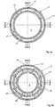
- the trim 2 further comprises a plurality of annular partition walls 20 orthogonal to the axis Y and extending through an annular interspace 11a from one to the other of said first and second cylinder 11, 12 in order to divide said trim 2 into a plurality of levels (nine levels 2a-i) in the embodiments of the attaché figure 2-4 ) axially distributed along the axis Y between said first and second openings 3, 4.
- Each level 2a-i comprises respective portions of the first and second cylinder 11, 12 and respective portions of the first and second plurality of holes 13, 14.
- Each of the levels 2a-i defines one of the partially open positions.
- the valve 1 comprises two stages and the trim 2 comprises exclusively the first and the second cylinder 11, 12.
- the valve 1 When the valve 1 is fully or partially open, i.e. when the plug 6 is remote from the first opening 3, a fluid flows from the first opening 3 to at least part of the levels 2a-i by reducing its energy pressure. Dividing the trim 2 in several levels a more efficient reduction of pressure is achieved as well as a reduction of noise.
- the fluid passes first through the second inner cylinder 12 which constitutes a first stage of pressure drop, then through the annular interspace 11a and finally through the first outer cylinder 11 which constitutes a second and last stage of pressure drop.
- the holes of the first and second plurality 13, 14 are dimensioned and positioned in such a way that:
- the holes of the first plurality 14 is neither partially aligned, along a radial direction orthogonal to the axis Y, with the holes of the second plurality 15.
- the holes of the first and second plurality 13, 14 are further dimensioned and positioned in such a way that:
- the valve 1 comprises three stages and the trim 2 comprises also a third cylinder 13 housed in the second cylinder 12 and coaxial with it.
- the third cylinder 13 comprises a third plurality 16 of radial through holes.
- Analogously to the first and second cylinder 11, 12, also the holes of the couple of adjacent cylinders constituted by the second and third cylinder 12, 13 are disposed in such a way that for each hole of one of the second and third cylinders the projection along a radial direction on the other of the second and third cylinders is spaced from each hole of the other of said second and third plurality of holes.
- the trim of the second embodiment comprises a second annular interspace 12a from one to the other of said second and third cylinder 12, 13.
- fluid flows from the first opening 3 to at least part of the levels 2a-i by reducing its energy pressure.
- the fluid passes first through the third cylinder 13, which constitutes a first stage of pressure drop, and then through the second annular interspace 12a. From the second annular interspace 12a the fluid passes to the second inner cylinder 12 which constitutes a second stage of pressure drop, then through the annular interspace 11a and finally through the first outer cylinder 11 which constitutes a third and last stage of pressure drop.
- valve 1 comprises four or more stages and the trim 2 comprises four or more cylinders each corresponding to a respective stage of pressure drop.
- the holes of the first and second plurality 13, 14 are further dimensioned and positioned in such a way that the above conditions a), b) and c) are fulfilled.
Landscapes
- Engineering & Computer Science (AREA)
- General Engineering & Computer Science (AREA)
- Mechanical Engineering (AREA)
- Details Of Valves (AREA)
- Sliding Valves (AREA)
- Fluid-Driven Valves (AREA)
Claims (5)
- Steuerventil (1), umfassend:- eine zylinderförmige hohle Garnitur (2), die eine innere Bohrung (5) definiert, welche sich entlang einer Achse (Y) zwischen einer ersten Öffnung (3) und einer zweiten Öffnung (4) erstreckt, wobei die erste Öffnung (3) einen Einlass des Ventils (1) definiert, wobei die Garnitur (2)- einen ersten äußeren Zylinder (11), der sich entlang der Achse (Y) erstreckt und eine erste Vielzahl (14) von radialen Durchgangslöchern, die einen Auslass der Garnitur definieren, umfasst,- einen zweiten Zylinder (12), der in dem ersten Zylinder (11) aufgenommen ist und damit koaxial verläuft, wobei der zweite Zylinder eine zweite Vielzahl (15) von radialen Durchgangslöchern umfasst,- einen Kegel (6), der so in der Größe bemessen ist, dass er in die Bohrung (5) passt und entlang der Achse (Y) gleitfähig über mehrere teilweise offene Positionen zwischen einer geschlossenen Position nahe an der ersten Öffnung (3) und einer vollständig offenen Position nahe an der zweiten Öffnung (4) beweglich ist, wobei in der vollständig offenen Position alle Öffnungen der ersten und zweiten Vielzahl (14, 15) von Durchgangslöchern mit der inneren Bohrung (5) in Verbindung stehen, und wobei in jeder der teilweise offenen Positionen nur ein jeweiliger Teil der Löcher der ersten und zweiten Vielzahl (14, 15) von Durchgangslöchern mit der inneren Bohrung (5) in Verbindung steht,- wobei die Löcher der ersten Vielzahl (14) einen kleineren Durchmesser als die Löcher der zweiten Vielzahl (15) aufweisen,- wobei die Anzahl der Löcher der ersten Vielzahl (14) größer als jene der Löcher der zweiten Vielzahl (15) ist,- wobei für jedes Loch (14, 15) eines aus dem ersten und dem zweiten Zylinder (11, 12) die Projektion entlang einer radialen Richtung auf den anderen aus dem ersten und dem zweiten Zylinder (12, 11) von jedem Loch (15, 14) der anderen aus der ersten und der zweiten Vielzahl beabstandet ist,- dadurch gekennzeichnet, dass die Garnitur (2) ferner mehrere ringförmige Trennwände (20) umfasst, die orthogonal zu der Achse (Y) verlaufen und sich durch einen ringförmigen Raum (11a) von einem zu dem anderen aus dem ersten und dem zweiten Zylinder (11, 12) erstrecken, um die Garnitur (2) in mehrere Ebenen (2a - i) zu teilen, die entlang der Achse (Y) zwischen der ersten und der zweiten Öffnung (3, 4) verteilt sind, wobei jede der Ebenen (2a - i) eine der teilweise offenen Positionen definiert.
- Steuerventil nach Anspruch 1, wobei die Garnitur (2) ferner wenigstens einen dritten Zylinder (13) umfasst, der in dem zweiten Zylinder (12) aufgenommen ist und damit koaxial verläuft, wobei der wenigstens dritte Zylinder (13) eine jeweilige dritte Mehrzahl (16) von radialen Durchgangslöchern umfasst, wobei die Löcher jedes Paars (11, 12; 12, 13) von benachbarten Zylindern in der Garnitur (2) auf eine solche Weise angeordnet sind, dass für jedes Loch von einem (11, 12; 12, 13) der benachbarten Zylinder die Projektion entlang einer radialen Richtung auf den anderen (12, 11; 13, 12) der benachbarten Zylinder von jedem Loch der Vielzahl von Löchern an dem anderen der benachbarten Zylinder beabstandet ist.
- Steuerventil nach Anspruch 1 oder Anspruch 2, wobei der Abstand (I) zwischen den Mitten von zwei Löchern (14) der ersten Vielzahl größer als 1,3d und kleiner als 3d ist, wobei d der durchschnittliche Durchmesser der Löcher der ersten Vielzahl ist.
- Steuerventil nach Anspruch 3, wobei die Löcher (14) der ersten Vielzahl alle den gleichen Durchmesser (d) aufweisen.
- Steuerventil nach einem der vorhergehenden Ansprüche, wobei die gesamte Querschnittfläche (A) der Löcher der ersten Vielzahl (14) in jeder Ebene größer als 1,1B und kleiner als 3B ist, wobei B die gesamte Querschnittfläche (B) der Löcher der zweiten Vielzahl (15) ist.
Applications Claiming Priority (2)
| Application Number | Priority Date | Filing Date | Title |
|---|---|---|---|
| IT000060A ITCO20130060A1 (it) | 2013-11-15 | 2013-11-15 | Valvola di controllo multistadio |
| PCT/EP2014/074571 WO2015071398A1 (en) | 2013-11-15 | 2014-11-14 | Multistage trim for control valves |
Publications (2)
| Publication Number | Publication Date |
|---|---|
| EP3069060A1 EP3069060A1 (de) | 2016-09-21 |
| EP3069060B1 true EP3069060B1 (de) | 2017-11-01 |
Family
ID=50001107
Family Applications (1)
| Application Number | Title | Priority Date | Filing Date |
|---|---|---|---|
| EP14798858.8A Active EP3069060B1 (de) | 2013-11-15 | 2014-11-14 | Mehrstufige verkleidung für steuerventile |
Country Status (7)
| Country | Link |
|---|---|
| US (1) | US9890874B2 (de) |
| EP (1) | EP3069060B1 (de) |
| JP (1) | JP6609731B2 (de) |
| KR (1) | KR102242216B1 (de) |
| CN (1) | CN105899863B (de) |
| IT (1) | ITCO20130060A1 (de) |
| WO (1) | WO2015071398A1 (de) |
Families Citing this family (3)
| Publication number | Priority date | Publication date | Assignee | Title |
|---|---|---|---|---|
| US10302224B2 (en) * | 2015-08-07 | 2019-05-28 | Marotta Controls, Inc. | Three-dimensional manufacturing of quieting valve having complex passages |
| US10551856B2 (en) * | 2017-02-23 | 2020-02-04 | Fisher Controls International Llc | Fluid control valve having discrete flow channels arranged to equalize the velocity of fluid at the perimeter of the valve port |
| DE102019118316A1 (de) * | 2019-07-05 | 2021-01-07 | Samson Aktiengesellschaft | Ventilgehäuse und Hubventil zum Steuern einer Prozessfluidströmung mit einem Ventilgehäuse |
Family Cites Families (19)
| Publication number | Priority date | Publication date | Assignee | Title |
|---|---|---|---|---|
| BR7408350D0 (pt) * | 1973-10-09 | 1975-07-29 | Fisher Controls Co | Aperfeicoamentos em valvula de controle de fluido e processo de regulagem de fluxo |
| US3954124A (en) * | 1973-12-05 | 1976-05-04 | Self Richard E | High energy loss nested sleeve fluid control device |
| JPS51142723A (en) * | 1975-06-03 | 1976-12-08 | Tokico Ltd | Low noise valve |
| US4617963A (en) * | 1983-06-23 | 1986-10-21 | Mcgraw-Edison Company | Control valve with anticavitation trim |
| CA1229024A (en) * | 1983-06-23 | 1987-11-10 | James A. Stares | Control valve with anticavitation trim |
| US4860993A (en) * | 1988-01-14 | 1989-08-29 | Teledyne Industries, Inc. | Valve design to reduce cavitation and noise |
| US5018703A (en) * | 1988-01-14 | 1991-05-28 | Teledyne Industries, Inc. | Valve design to reduce cavitation and noise |
| JP3406357B2 (ja) * | 1993-09-27 | 2003-05-12 | 株式会社本山製作所 | ケージ型低騒音弁 |
| JP3821918B2 (ja) * | 1997-07-07 | 2006-09-13 | 株式会社本山製作所 | 調節弁用ケージ、調節弁および配管サイレンサー |
| US6935371B2 (en) | 2002-02-22 | 2005-08-30 | Dresser, Inc. | High capacity globe valve |
| US6766826B2 (en) | 2002-04-12 | 2004-07-27 | Fisher Controls International, Inc. | Low noise fluid control valve |
| US6886596B2 (en) | 2002-04-12 | 2005-05-03 | Control Components, Inc. | Rotary drag valve |
| US20040118462A1 (en) | 2002-12-19 | 2004-06-24 | Baumann Hans D. | Control valve with low noise and enhanced flow characteristics |
| JP2009209976A (ja) * | 2008-02-29 | 2009-09-17 | Osaka Gas Co Ltd | サイレンサおよびこれを備える圧力制御装置 |
| CN101270819A (zh) * | 2008-05-08 | 2008-09-24 | 四川华林自控科技有限公司 | 高压差套筒阀 |
| CN201348054Y (zh) * | 2008-12-21 | 2009-11-18 | 重庆川仪自动化股份有限公司 | 高温蒸汽调节阀 |
| CN201802972U (zh) * | 2010-09-15 | 2011-04-20 | 南通市电站阀门有限公司 | 低压差排放的可调节疏水阀 |
| US20130320252A1 (en) * | 2011-02-17 | 2013-12-05 | Egc Enterprises, Inc. | Control valve assembly |
| CN202056500U (zh) * | 2011-05-30 | 2011-11-30 | 南通市电站阀门有限公司 | 带减压节流盘的超临界调节疏水阀 |
-
2013
- 2013-11-15 IT IT000060A patent/ITCO20130060A1/it unknown
-
2014
- 2014-11-14 EP EP14798858.8A patent/EP3069060B1/de active Active
- 2014-11-14 JP JP2016529879A patent/JP6609731B2/ja not_active Expired - Fee Related
- 2014-11-14 KR KR1020167015641A patent/KR102242216B1/ko active Active
- 2014-11-14 WO PCT/EP2014/074571 patent/WO2015071398A1/en not_active Ceased
- 2014-11-14 US US15/036,680 patent/US9890874B2/en active Active
- 2014-11-14 CN CN201480062348.1A patent/CN105899863B/zh active Active
Non-Patent Citations (1)
| Title |
|---|
| None * |
Also Published As
| Publication number | Publication date |
|---|---|
| JP2016540937A (ja) | 2016-12-28 |
| CN105899863A (zh) | 2016-08-24 |
| WO2015071398A1 (en) | 2015-05-21 |
| US20160281880A1 (en) | 2016-09-29 |
| ITCO20130060A1 (it) | 2015-05-16 |
| CN105899863B (zh) | 2018-03-23 |
| US9890874B2 (en) | 2018-02-13 |
| EP3069060A1 (de) | 2016-09-21 |
| KR102242216B1 (ko) | 2021-04-21 |
| KR20160085871A (ko) | 2016-07-18 |
| JP6609731B2 (ja) | 2019-11-27 |
Similar Documents
| Publication | Publication Date | Title |
|---|---|---|
| US9151407B2 (en) | Valve cage having zero dead band between noise abatement and high capacity flow sections | |
| CN103244747B (zh) | 用于加压管道的减压器及阀组件 | |
| US10883765B2 (en) | Heat exchanger with heilical flights and tubes | |
| EP3069060B1 (de) | Mehrstufige verkleidung für steuerventile | |
| US9605771B2 (en) | Flow cage assemblies | |
| RU2019133860A (ru) | Регулирующий клапан с высокоэффективной клеткой | |
| CN209839190U (zh) | 分级降压的阀笼组合结构及安装阀笼组合结构的调节阀 | |
| US8430131B2 (en) | Noise control via outlet jet frequency dispersal | |
| RU2008103000A (ru) | Смеситель потоков с изменяемым сечением для двухконтурного турбореактивного двигателя сверхзвукового самолета | |
| CN112253842B (zh) | 低噪声减压阀 | |
| US10563766B2 (en) | Packing case for reciprocating machine and method of assembling the same | |
| EP2716945A1 (de) | Durchflussregler für ein Ventil | |
| CN114233901B (zh) | 一种大压差低减压比的蒸汽降噪减压装置 | |
| CN114215960A (zh) | 节流阀 | |
| US10253647B2 (en) | Regulating valve and turbine | |
| CN205173562U (zh) | 一种新型逻辑选择阀阀杆结构 | |
| KR20180019723A (ko) | 펌프 성능 특성 제어를 위한 배출 케이싱 인서트 | |
| RU2024129261A (ru) | Многозазорный клапан и гомогенизирующее устройство, содержащее такой многозазорный клапан | |
| CS254783B1 (cs) | Vícestupňový ventil |
Legal Events
| Date | Code | Title | Description |
|---|---|---|---|
| PUAI | Public reference made under article 153(3) epc to a published international application that has entered the european phase |
Free format text: ORIGINAL CODE: 0009012 |
|
| 17P | Request for examination filed |
Effective date: 20160615 |
|
| AK | Designated contracting states |
Kind code of ref document: A1 Designated state(s): AL AT BE BG CH CY CZ DE DK EE ES FI FR GB GR HR HU IE IS IT LI LT LU LV MC MK MT NL NO PL PT RO RS SE SI SK SM TR |
|
| AX | Request for extension of the european patent |
Extension state: BA ME |
|
| DAX | Request for extension of the european patent (deleted) | ||
| GRAP | Despatch of communication of intention to grant a patent |
Free format text: ORIGINAL CODE: EPIDOSNIGR1 |
|
| INTG | Intention to grant announced |
Effective date: 20170726 |
|
| GRAS | Grant fee paid |
Free format text: ORIGINAL CODE: EPIDOSNIGR3 |
|
| GRAA | (expected) grant |
Free format text: ORIGINAL CODE: 0009210 |
|
| AK | Designated contracting states |
Kind code of ref document: B1 Designated state(s): AL AT BE BG CH CY CZ DE DK EE ES FI FR GB GR HR HU IE IS IT LI LT LU LV MC MK MT NL NO PL PT RO RS SE SI SK SM TR |
|
| REG | Reference to a national code |
Ref country code: GB Ref legal event code: FG4D |
|
| REG | Reference to a national code |
Ref country code: CH Ref legal event code: EP Ref country code: AT Ref legal event code: REF Ref document number: 942381 Country of ref document: AT Kind code of ref document: T Effective date: 20171115 |
|
| REG | Reference to a national code |
Ref country code: IE Ref legal event code: FG4D |
|
| REG | Reference to a national code |
Ref country code: DE Ref legal event code: R096 Ref document number: 602014016713 Country of ref document: DE |
|
| REG | Reference to a national code |
Ref country code: NL Ref legal event code: MP Effective date: 20171101 |
|
| REG | Reference to a national code |
Ref country code: LT Ref legal event code: MG4D |
|
| REG | Reference to a national code |
Ref country code: AT Ref legal event code: MK05 Ref document number: 942381 Country of ref document: AT Kind code of ref document: T Effective date: 20171101 |
|
| PG25 | Lapsed in a contracting state [announced via postgrant information from national office to epo] |
Ref country code: SE Free format text: LAPSE BECAUSE OF FAILURE TO SUBMIT A TRANSLATION OF THE DESCRIPTION OR TO PAY THE FEE WITHIN THE PRESCRIBED TIME-LIMIT Effective date: 20171101 Ref country code: ES Free format text: LAPSE BECAUSE OF FAILURE TO SUBMIT A TRANSLATION OF THE DESCRIPTION OR TO PAY THE FEE WITHIN THE PRESCRIBED TIME-LIMIT Effective date: 20171101 Ref country code: NO Free format text: LAPSE BECAUSE OF FAILURE TO SUBMIT A TRANSLATION OF THE DESCRIPTION OR TO PAY THE FEE WITHIN THE PRESCRIBED TIME-LIMIT Effective date: 20180201 Ref country code: FI Free format text: LAPSE BECAUSE OF FAILURE TO SUBMIT A TRANSLATION OF THE DESCRIPTION OR TO PAY THE FEE WITHIN THE PRESCRIBED TIME-LIMIT Effective date: 20171101 Ref country code: LT Free format text: LAPSE BECAUSE OF FAILURE TO SUBMIT A TRANSLATION OF THE DESCRIPTION OR TO PAY THE FEE WITHIN THE PRESCRIBED TIME-LIMIT Effective date: 20171101 Ref country code: NL Free format text: LAPSE BECAUSE OF FAILURE TO SUBMIT A TRANSLATION OF THE DESCRIPTION OR TO PAY THE FEE WITHIN THE PRESCRIBED TIME-LIMIT Effective date: 20171101 |
|
| PG25 | Lapsed in a contracting state [announced via postgrant information from national office to epo] |
Ref country code: GR Free format text: LAPSE BECAUSE OF FAILURE TO SUBMIT A TRANSLATION OF THE DESCRIPTION OR TO PAY THE FEE WITHIN THE PRESCRIBED TIME-LIMIT Effective date: 20180202 Ref country code: AT Free format text: LAPSE BECAUSE OF FAILURE TO SUBMIT A TRANSLATION OF THE DESCRIPTION OR TO PAY THE FEE WITHIN THE PRESCRIBED TIME-LIMIT Effective date: 20171101 Ref country code: LV Free format text: LAPSE BECAUSE OF FAILURE TO SUBMIT A TRANSLATION OF THE DESCRIPTION OR TO PAY THE FEE WITHIN THE PRESCRIBED TIME-LIMIT Effective date: 20171101 Ref country code: RS Free format text: LAPSE BECAUSE OF FAILURE TO SUBMIT A TRANSLATION OF THE DESCRIPTION OR TO PAY THE FEE WITHIN THE PRESCRIBED TIME-LIMIT Effective date: 20171101 Ref country code: HR Free format text: LAPSE BECAUSE OF FAILURE TO SUBMIT A TRANSLATION OF THE DESCRIPTION OR TO PAY THE FEE WITHIN THE PRESCRIBED TIME-LIMIT Effective date: 20171101 Ref country code: IS Free format text: LAPSE BECAUSE OF FAILURE TO SUBMIT A TRANSLATION OF THE DESCRIPTION OR TO PAY THE FEE WITHIN THE PRESCRIBED TIME-LIMIT Effective date: 20180301 Ref country code: BG Free format text: LAPSE BECAUSE OF FAILURE TO SUBMIT A TRANSLATION OF THE DESCRIPTION OR TO PAY THE FEE WITHIN THE PRESCRIBED TIME-LIMIT Effective date: 20180201 |
|
| PG25 | Lapsed in a contracting state [announced via postgrant information from national office to epo] |
Ref country code: CH Free format text: LAPSE BECAUSE OF NON-PAYMENT OF DUE FEES Effective date: 20171130 Ref country code: DK Free format text: LAPSE BECAUSE OF FAILURE TO SUBMIT A TRANSLATION OF THE DESCRIPTION OR TO PAY THE FEE WITHIN THE PRESCRIBED TIME-LIMIT Effective date: 20171101 Ref country code: LI Free format text: LAPSE BECAUSE OF NON-PAYMENT OF DUE FEES Effective date: 20171130 Ref country code: CY Free format text: LAPSE BECAUSE OF FAILURE TO SUBMIT A TRANSLATION OF THE DESCRIPTION OR TO PAY THE FEE WITHIN THE PRESCRIBED TIME-LIMIT Effective date: 20171101 Ref country code: SK Free format text: LAPSE BECAUSE OF FAILURE TO SUBMIT A TRANSLATION OF THE DESCRIPTION OR TO PAY THE FEE WITHIN THE PRESCRIBED TIME-LIMIT Effective date: 20171101 Ref country code: EE Free format text: LAPSE BECAUSE OF FAILURE TO SUBMIT A TRANSLATION OF THE DESCRIPTION OR TO PAY THE FEE WITHIN THE PRESCRIBED TIME-LIMIT Effective date: 20171101 |
|
| REG | Reference to a national code |
Ref country code: DE Ref legal event code: R097 Ref document number: 602014016713 Country of ref document: DE |
|
| PG25 | Lapsed in a contracting state [announced via postgrant information from national office to epo] |
Ref country code: IT Free format text: LAPSE BECAUSE OF FAILURE TO SUBMIT A TRANSLATION OF THE DESCRIPTION OR TO PAY THE FEE WITHIN THE PRESCRIBED TIME-LIMIT Effective date: 20171101 Ref country code: PL Free format text: LAPSE BECAUSE OF FAILURE TO SUBMIT A TRANSLATION OF THE DESCRIPTION OR TO PAY THE FEE WITHIN THE PRESCRIBED TIME-LIMIT Effective date: 20171101 Ref country code: SM Free format text: LAPSE BECAUSE OF FAILURE TO SUBMIT A TRANSLATION OF THE DESCRIPTION OR TO PAY THE FEE WITHIN THE PRESCRIBED TIME-LIMIT Effective date: 20171101 Ref country code: RO Free format text: LAPSE BECAUSE OF FAILURE TO SUBMIT A TRANSLATION OF THE DESCRIPTION OR TO PAY THE FEE WITHIN THE PRESCRIBED TIME-LIMIT Effective date: 20171101 Ref country code: LU Free format text: LAPSE BECAUSE OF NON-PAYMENT OF DUE FEES Effective date: 20171114 |
|
| REG | Reference to a national code |
Ref country code: BE Ref legal event code: MM Effective date: 20171130 |
|
| REG | Reference to a national code |
Ref country code: IE Ref legal event code: MM4A |
|
| PLBE | No opposition filed within time limit |
Free format text: ORIGINAL CODE: 0009261 |
|
| STAA | Information on the status of an ep patent application or granted ep patent |
Free format text: STATUS: NO OPPOSITION FILED WITHIN TIME LIMIT |
|
| PG25 | Lapsed in a contracting state [announced via postgrant information from national office to epo] |
Ref country code: MT Free format text: LAPSE BECAUSE OF NON-PAYMENT OF DUE FEES Effective date: 20171114 |
|
| REG | Reference to a national code |
Ref country code: FR Ref legal event code: ST Effective date: 20180905 |
|
| 26N | No opposition filed |
Effective date: 20180802 |
|
| PG25 | Lapsed in a contracting state [announced via postgrant information from national office to epo] |
Ref country code: FR Free format text: LAPSE BECAUSE OF NON-PAYMENT OF DUE FEES Effective date: 20180102 Ref country code: IE Free format text: LAPSE BECAUSE OF NON-PAYMENT OF DUE FEES Effective date: 20171114 |
|
| PG25 | Lapsed in a contracting state [announced via postgrant information from national office to epo] |
Ref country code: SI Free format text: LAPSE BECAUSE OF FAILURE TO SUBMIT A TRANSLATION OF THE DESCRIPTION OR TO PAY THE FEE WITHIN THE PRESCRIBED TIME-LIMIT Effective date: 20171101 Ref country code: BE Free format text: LAPSE BECAUSE OF NON-PAYMENT OF DUE FEES Effective date: 20171130 |
|
| PG25 | Lapsed in a contracting state [announced via postgrant information from national office to epo] |
Ref country code: MC Free format text: LAPSE BECAUSE OF FAILURE TO SUBMIT A TRANSLATION OF THE DESCRIPTION OR TO PAY THE FEE WITHIN THE PRESCRIBED TIME-LIMIT Effective date: 20171101 Ref country code: HU Free format text: LAPSE BECAUSE OF FAILURE TO SUBMIT A TRANSLATION OF THE DESCRIPTION OR TO PAY THE FEE WITHIN THE PRESCRIBED TIME-LIMIT; INVALID AB INITIO Effective date: 20141114 |
|
| PG25 | Lapsed in a contracting state [announced via postgrant information from national office to epo] |
Ref country code: MK Free format text: LAPSE BECAUSE OF FAILURE TO SUBMIT A TRANSLATION OF THE DESCRIPTION OR TO PAY THE FEE WITHIN THE PRESCRIBED TIME-LIMIT Effective date: 20171101 |
|
| PG25 | Lapsed in a contracting state [announced via postgrant information from national office to epo] |
Ref country code: TR Free format text: LAPSE BECAUSE OF FAILURE TO SUBMIT A TRANSLATION OF THE DESCRIPTION OR TO PAY THE FEE WITHIN THE PRESCRIBED TIME-LIMIT Effective date: 20171101 |
|
| PG25 | Lapsed in a contracting state [announced via postgrant information from national office to epo] |
Ref country code: PT Free format text: LAPSE BECAUSE OF FAILURE TO SUBMIT A TRANSLATION OF THE DESCRIPTION OR TO PAY THE FEE WITHIN THE PRESCRIBED TIME-LIMIT Effective date: 20171101 |
|
| PG25 | Lapsed in a contracting state [announced via postgrant information from national office to epo] |
Ref country code: AL Free format text: LAPSE BECAUSE OF FAILURE TO SUBMIT A TRANSLATION OF THE DESCRIPTION OR TO PAY THE FEE WITHIN THE PRESCRIBED TIME-LIMIT Effective date: 20171101 |
|
| REG | Reference to a national code |
Ref country code: GB Ref legal event code: 732E Free format text: REGISTERED BETWEEN 20220728 AND 20220803 |
|
| REG | Reference to a national code |
Ref country code: DE Ref legal event code: R081 Ref document number: 602014016713 Country of ref document: DE Owner name: NUOVO PIGNONE TECNOLOGIE - S.R.L., IT Free format text: FORMER OWNER: NUOVO PIGNONE S.R.L., 50127 FLORENCE, IT |
|
| PGFP | Annual fee paid to national office [announced via postgrant information from national office to epo] |
Ref country code: DE Payment date: 20251022 Year of fee payment: 12 |
|
| PGFP | Annual fee paid to national office [announced via postgrant information from national office to epo] |
Ref country code: GB Payment date: 20251023 Year of fee payment: 12 |
|
| PGFP | Annual fee paid to national office [announced via postgrant information from national office to epo] |
Ref country code: CZ Payment date: 20251030 Year of fee payment: 12 |