EP3068604B1 - Method for ultrasonic welding of thermoplastics parts - Google Patents
Method for ultrasonic welding of thermoplastics parts Download PDFInfo
- Publication number
- EP3068604B1 EP3068604B1 EP14861847.3A EP14861847A EP3068604B1 EP 3068604 B1 EP3068604 B1 EP 3068604B1 EP 14861847 A EP14861847 A EP 14861847A EP 3068604 B1 EP3068604 B1 EP 3068604B1
- Authority
- EP
- European Patent Office
- Prior art keywords
- energy director
- thermoplastic part
- director
- fabric
- film
- Prior art date
- Legal status (The legal status is an assumption and is not a legal conclusion. Google has not performed a legal analysis and makes no representation as to the accuracy of the status listed.)
- Active
Links
- 229920001169 thermoplastic Polymers 0.000 title claims description 54
- 239000004416 thermosoftening plastic Substances 0.000 title claims description 54
- 238000003466 welding Methods 0.000 title claims description 40
- 238000000034 method Methods 0.000 title claims description 34
- 239000004744 fabric Substances 0.000 claims description 22
- 238000005304 joining Methods 0.000 claims description 12
- 239000004033 plastic Substances 0.000 claims description 12
- 229920003023 plastic Polymers 0.000 claims description 12
- 239000000463 material Substances 0.000 claims description 7
- 238000002844 melting Methods 0.000 claims description 6
- 230000008018 melting Effects 0.000 claims description 6
- 230000008569 process Effects 0.000 claims description 6
- 238000003825 pressing Methods 0.000 claims description 5
- 230000003111 delayed effect Effects 0.000 claims description 4
- 238000003801 milling Methods 0.000 claims description 2
- 238000002474 experimental method Methods 0.000 description 4
- 238000012986 modification Methods 0.000 description 4
- 230000004048 modification Effects 0.000 description 4
- 238000002604 ultrasonography Methods 0.000 description 4
- 230000008901 benefit Effects 0.000 description 3
- 238000003754 machining Methods 0.000 description 3
- 238000004519 manufacturing process Methods 0.000 description 3
- 230000013011 mating Effects 0.000 description 3
- 238000000465 moulding Methods 0.000 description 3
- 229910000831 Steel Inorganic materials 0.000 description 2
- 238000004806 packaging method and process Methods 0.000 description 2
- 239000010959 steel Substances 0.000 description 2
- 230000008859 change Effects 0.000 description 1
- 230000003749 cleanliness Effects 0.000 description 1
- 238000010276 construction Methods 0.000 description 1
- 238000005520 cutting process Methods 0.000 description 1
- 230000000694 effects Effects 0.000 description 1
- 238000009760 electrical discharge machining Methods 0.000 description 1
- 239000000203 mixture Substances 0.000 description 1
- 239000004417 polycarbonate Substances 0.000 description 1
- 229920000515 polycarbonate Polymers 0.000 description 1
Images

Classifications
-
- B—PERFORMING OPERATIONS; TRANSPORTING
- B29—WORKING OF PLASTICS; WORKING OF SUBSTANCES IN A PLASTIC STATE IN GENERAL
- B29C—SHAPING OR JOINING OF PLASTICS; SHAPING OF MATERIAL IN A PLASTIC STATE, NOT OTHERWISE PROVIDED FOR; AFTER-TREATMENT OF THE SHAPED PRODUCTS, e.g. REPAIRING
- B29C65/00—Joining or sealing of preformed parts, e.g. welding of plastics materials; Apparatus therefor
- B29C65/02—Joining or sealing of preformed parts, e.g. welding of plastics materials; Apparatus therefor by heating, with or without pressure
- B29C65/08—Joining or sealing of preformed parts, e.g. welding of plastics materials; Apparatus therefor by heating, with or without pressure using ultrasonic vibrations
-
- B—PERFORMING OPERATIONS; TRANSPORTING
- B29—WORKING OF PLASTICS; WORKING OF SUBSTANCES IN A PLASTIC STATE IN GENERAL
- B29C—SHAPING OR JOINING OF PLASTICS; SHAPING OF MATERIAL IN A PLASTIC STATE, NOT OTHERWISE PROVIDED FOR; AFTER-TREATMENT OF THE SHAPED PRODUCTS, e.g. REPAIRING
- B29C66/00—General aspects of processes or apparatus for joining preformed parts
- B29C66/01—General aspects dealing with the joint area or with the area to be joined
- B29C66/05—Particular design of joint configurations
- B29C66/10—Particular design of joint configurations particular design of the joint cross-sections
- B29C66/11—Joint cross-sections comprising a single joint-segment, i.e. one of the parts to be joined comprising a single joint-segment in the joint cross-section
- B29C66/112—Single lapped joints
-
- B—PERFORMING OPERATIONS; TRANSPORTING
- B29—WORKING OF PLASTICS; WORKING OF SUBSTANCES IN A PLASTIC STATE IN GENERAL
- B29C—SHAPING OR JOINING OF PLASTICS; SHAPING OF MATERIAL IN A PLASTIC STATE, NOT OTHERWISE PROVIDED FOR; AFTER-TREATMENT OF THE SHAPED PRODUCTS, e.g. REPAIRING
- B29C66/00—General aspects of processes or apparatus for joining preformed parts
- B29C66/01—General aspects dealing with the joint area or with the area to be joined
- B29C66/05—Particular design of joint configurations
- B29C66/10—Particular design of joint configurations particular design of the joint cross-sections
- B29C66/11—Joint cross-sections comprising a single joint-segment, i.e. one of the parts to be joined comprising a single joint-segment in the joint cross-section
- B29C66/114—Single butt joints
-
- B—PERFORMING OPERATIONS; TRANSPORTING
- B29—WORKING OF PLASTICS; WORKING OF SUBSTANCES IN A PLASTIC STATE IN GENERAL
- B29C—SHAPING OR JOINING OF PLASTICS; SHAPING OF MATERIAL IN A PLASTIC STATE, NOT OTHERWISE PROVIDED FOR; AFTER-TREATMENT OF THE SHAPED PRODUCTS, e.g. REPAIRING
- B29C66/00—General aspects of processes or apparatus for joining preformed parts
- B29C66/01—General aspects dealing with the joint area or with the area to be joined
- B29C66/05—Particular design of joint configurations
- B29C66/302—Particular design of joint configurations the area to be joined comprising melt initiators
- B29C66/3022—Particular design of joint configurations the area to be joined comprising melt initiators said melt initiators being integral with at least one of the parts to be joined
- B29C66/30223—Particular design of joint configurations the area to be joined comprising melt initiators said melt initiators being integral with at least one of the parts to be joined said melt initiators being rib-like
-
- B—PERFORMING OPERATIONS; TRANSPORTING
- B29—WORKING OF PLASTICS; WORKING OF SUBSTANCES IN A PLASTIC STATE IN GENERAL
- B29C—SHAPING OR JOINING OF PLASTICS; SHAPING OF MATERIAL IN A PLASTIC STATE, NOT OTHERWISE PROVIDED FOR; AFTER-TREATMENT OF THE SHAPED PRODUCTS, e.g. REPAIRING
- B29C66/00—General aspects of processes or apparatus for joining preformed parts
- B29C66/50—General aspects of joining tubular articles; General aspects of joining long products, i.e. bars or profiled elements; General aspects of joining single elements to tubular articles, hollow articles or bars; General aspects of joining several hollow-preforms to form hollow or tubular articles
- B29C66/51—Joining tubular articles, profiled elements or bars; Joining single elements to tubular articles, hollow articles or bars; Joining several hollow-preforms to form hollow or tubular articles
- B29C66/54—Joining several hollow-preforms, e.g. half-shells, to form hollow articles, e.g. for making balls, containers; Joining several hollow-preforms, e.g. half-cylinders, to form tubular articles
- B29C66/542—Joining several hollow-preforms, e.g. half-shells, to form hollow articles, e.g. for making balls, containers; Joining several hollow-preforms, e.g. half-cylinders, to form tubular articles joining hollow covers or hollow bottoms to open ends of container bodies
-
- B—PERFORMING OPERATIONS; TRANSPORTING
- B29—WORKING OF PLASTICS; WORKING OF SUBSTANCES IN A PLASTIC STATE IN GENERAL
- B29C—SHAPING OR JOINING OF PLASTICS; SHAPING OF MATERIAL IN A PLASTIC STATE, NOT OTHERWISE PROVIDED FOR; AFTER-TREATMENT OF THE SHAPED PRODUCTS, e.g. REPAIRING
- B29C66/00—General aspects of processes or apparatus for joining preformed parts
- B29C66/70—General aspects of processes or apparatus for joining preformed parts characterised by the composition, physical properties or the structure of the material of the parts to be joined; Joining with non-plastics material
- B29C66/73—General aspects of processes or apparatus for joining preformed parts characterised by the composition, physical properties or the structure of the material of the parts to be joined; Joining with non-plastics material characterised by the intensive physical properties of the material of the parts to be joined, by the optical properties of the material of the parts to be joined, by the extensive physical properties of the parts to be joined, by the state of the material of the parts to be joined or by the material of the parts to be joined being a thermoplastic or a thermoset
- B29C66/739—General aspects of processes or apparatus for joining preformed parts characterised by the composition, physical properties or the structure of the material of the parts to be joined; Joining with non-plastics material characterised by the intensive physical properties of the material of the parts to be joined, by the optical properties of the material of the parts to be joined, by the extensive physical properties of the parts to be joined, by the state of the material of the parts to be joined or by the material of the parts to be joined being a thermoplastic or a thermoset characterised by the material of the parts to be joined being a thermoplastic or a thermoset
- B29C66/7392—General aspects of processes or apparatus for joining preformed parts characterised by the composition, physical properties or the structure of the material of the parts to be joined; Joining with non-plastics material characterised by the intensive physical properties of the material of the parts to be joined, by the optical properties of the material of the parts to be joined, by the extensive physical properties of the parts to be joined, by the state of the material of the parts to be joined or by the material of the parts to be joined being a thermoplastic or a thermoset characterised by the material of the parts to be joined being a thermoplastic or a thermoset characterised by the material of at least one of the parts being a thermoplastic
- B29C66/73921—General aspects of processes or apparatus for joining preformed parts characterised by the composition, physical properties or the structure of the material of the parts to be joined; Joining with non-plastics material characterised by the intensive physical properties of the material of the parts to be joined, by the optical properties of the material of the parts to be joined, by the extensive physical properties of the parts to be joined, by the state of the material of the parts to be joined or by the material of the parts to be joined being a thermoplastic or a thermoset characterised by the material of the parts to be joined being a thermoplastic or a thermoset characterised by the material of at least one of the parts being a thermoplastic characterised by the materials of both parts being thermoplastics
-
- B—PERFORMING OPERATIONS; TRANSPORTING
- B29—WORKING OF PLASTICS; WORKING OF SUBSTANCES IN A PLASTIC STATE IN GENERAL
- B29C—SHAPING OR JOINING OF PLASTICS; SHAPING OF MATERIAL IN A PLASTIC STATE, NOT OTHERWISE PROVIDED FOR; AFTER-TREATMENT OF THE SHAPED PRODUCTS, e.g. REPAIRING
- B29C66/00—General aspects of processes or apparatus for joining preformed parts
- B29C66/80—General aspects of machine operations or constructions and parts thereof
- B29C66/83—General aspects of machine operations or constructions and parts thereof characterised by the movement of the joining or pressing tools
- B29C66/832—Reciprocating joining or pressing tools
- B29C66/8322—Joining or pressing tools reciprocating along one axis
-
- B—PERFORMING OPERATIONS; TRANSPORTING
- B29—WORKING OF PLASTICS; WORKING OF SUBSTANCES IN A PLASTIC STATE IN GENERAL
- B29C—SHAPING OR JOINING OF PLASTICS; SHAPING OF MATERIAL IN A PLASTIC STATE, NOT OTHERWISE PROVIDED FOR; AFTER-TREATMENT OF THE SHAPED PRODUCTS, e.g. REPAIRING
- B29C66/00—General aspects of processes or apparatus for joining preformed parts
- B29C66/90—Measuring or controlling the joining process
- B29C66/92—Measuring or controlling the joining process by measuring or controlling the pressure, the force, the mechanical power or the displacement of the joining tools
- B29C66/924—Measuring or controlling the joining process by measuring or controlling the pressure, the force, the mechanical power or the displacement of the joining tools by controlling or regulating the pressure, the force, the mechanical power or the displacement of the joining tools
- B29C66/9261—Measuring or controlling the joining process by measuring or controlling the pressure, the force, the mechanical power or the displacement of the joining tools by controlling or regulating the pressure, the force, the mechanical power or the displacement of the joining tools by controlling or regulating the displacement of the joining tools
- B29C66/92611—Measuring or controlling the joining process by measuring or controlling the pressure, the force, the mechanical power or the displacement of the joining tools by controlling or regulating the pressure, the force, the mechanical power or the displacement of the joining tools by controlling or regulating the displacement of the joining tools by controlling or regulating the gap between the joining tools
- B29C66/92615—Measuring or controlling the joining process by measuring or controlling the pressure, the force, the mechanical power or the displacement of the joining tools by controlling or regulating the pressure, the force, the mechanical power or the displacement of the joining tools by controlling or regulating the displacement of the joining tools by controlling or regulating the gap between the joining tools the gap being non-constant over time
-
- B—PERFORMING OPERATIONS; TRANSPORTING
- B29—WORKING OF PLASTICS; WORKING OF SUBSTANCES IN A PLASTIC STATE IN GENERAL
- B29C—SHAPING OR JOINING OF PLASTICS; SHAPING OF MATERIAL IN A PLASTIC STATE, NOT OTHERWISE PROVIDED FOR; AFTER-TREATMENT OF THE SHAPED PRODUCTS, e.g. REPAIRING
- B29C66/00—General aspects of processes or apparatus for joining preformed parts
- B29C66/90—Measuring or controlling the joining process
- B29C66/92—Measuring or controlling the joining process by measuring or controlling the pressure, the force, the mechanical power or the displacement of the joining tools
- B29C66/929—Measuring or controlling the joining process by measuring or controlling the pressure, the force, the mechanical power or the displacement of the joining tools characterized by specific pressure, force, mechanical power or displacement values or ranges
- B29C66/9292—Measuring or controlling the joining process by measuring or controlling the pressure, the force, the mechanical power or the displacement of the joining tools characterized by specific pressure, force, mechanical power or displacement values or ranges in explicit relation to another variable, e.g. pressure diagrams
- B29C66/92921—Measuring or controlling the joining process by measuring or controlling the pressure, the force, the mechanical power or the displacement of the joining tools characterized by specific pressure, force, mechanical power or displacement values or ranges in explicit relation to another variable, e.g. pressure diagrams in specific relation to time, e.g. pressure-time diagrams
-
- B—PERFORMING OPERATIONS; TRANSPORTING
- B29—WORKING OF PLASTICS; WORKING OF SUBSTANCES IN A PLASTIC STATE IN GENERAL
- B29C—SHAPING OR JOINING OF PLASTICS; SHAPING OF MATERIAL IN A PLASTIC STATE, NOT OTHERWISE PROVIDED FOR; AFTER-TREATMENT OF THE SHAPED PRODUCTS, e.g. REPAIRING
- B29C66/00—General aspects of processes or apparatus for joining preformed parts
- B29C66/90—Measuring or controlling the joining process
- B29C66/95—Measuring or controlling the joining process by measuring or controlling specific variables not covered by groups B29C66/91 - B29C66/94
- B29C66/951—Measuring or controlling the joining process by measuring or controlling specific variables not covered by groups B29C66/91 - B29C66/94 by measuring or controlling the vibration frequency and/or the vibration amplitude of vibrating joining tools, e.g. of ultrasonic welding tools
-
- B—PERFORMING OPERATIONS; TRANSPORTING
- B29—WORKING OF PLASTICS; WORKING OF SUBSTANCES IN A PLASTIC STATE IN GENERAL
- B29C—SHAPING OR JOINING OF PLASTICS; SHAPING OF MATERIAL IN A PLASTIC STATE, NOT OTHERWISE PROVIDED FOR; AFTER-TREATMENT OF THE SHAPED PRODUCTS, e.g. REPAIRING
- B29C66/00—General aspects of processes or apparatus for joining preformed parts
- B29C66/01—General aspects dealing with the joint area or with the area to be joined
- B29C66/05—Particular design of joint configurations
- B29C66/10—Particular design of joint configurations particular design of the joint cross-sections
- B29C66/12—Joint cross-sections combining only two joint-segments; Tongue and groove joints; Tenon and mortise joints; Stepped joint cross-sections
- B29C66/122—Joint cross-sections combining only two joint-segments, i.e. one of the parts to be joined comprising only two joint-segments in the joint cross-section
- B29C66/1222—Joint cross-sections combining only two joint-segments, i.e. one of the parts to be joined comprising only two joint-segments in the joint cross-section comprising at least a lapped joint-segment
-
- B—PERFORMING OPERATIONS; TRANSPORTING
- B29—WORKING OF PLASTICS; WORKING OF SUBSTANCES IN A PLASTIC STATE IN GENERAL
- B29C—SHAPING OR JOINING OF PLASTICS; SHAPING OF MATERIAL IN A PLASTIC STATE, NOT OTHERWISE PROVIDED FOR; AFTER-TREATMENT OF THE SHAPED PRODUCTS, e.g. REPAIRING
- B29C66/00—General aspects of processes or apparatus for joining preformed parts
- B29C66/01—General aspects dealing with the joint area or with the area to be joined
- B29C66/05—Particular design of joint configurations
- B29C66/10—Particular design of joint configurations particular design of the joint cross-sections
- B29C66/12—Joint cross-sections combining only two joint-segments; Tongue and groove joints; Tenon and mortise joints; Stepped joint cross-sections
- B29C66/122—Joint cross-sections combining only two joint-segments, i.e. one of the parts to be joined comprising only two joint-segments in the joint cross-section
- B29C66/1224—Joint cross-sections combining only two joint-segments, i.e. one of the parts to be joined comprising only two joint-segments in the joint cross-section comprising at least a butt joint-segment
-
- B—PERFORMING OPERATIONS; TRANSPORTING
- B29—WORKING OF PLASTICS; WORKING OF SUBSTANCES IN A PLASTIC STATE IN GENERAL
- B29C—SHAPING OR JOINING OF PLASTICS; SHAPING OF MATERIAL IN A PLASTIC STATE, NOT OTHERWISE PROVIDED FOR; AFTER-TREATMENT OF THE SHAPED PRODUCTS, e.g. REPAIRING
- B29C66/00—General aspects of processes or apparatus for joining preformed parts
- B29C66/01—General aspects dealing with the joint area or with the area to be joined
- B29C66/05—Particular design of joint configurations
- B29C66/20—Particular design of joint configurations particular design of the joint lines, e.g. of the weld lines
- B29C66/24—Particular design of joint configurations particular design of the joint lines, e.g. of the weld lines said joint lines being closed or non-straight
- B29C66/242—Particular design of joint configurations particular design of the joint lines, e.g. of the weld lines said joint lines being closed or non-straight said joint lines being closed, i.e. forming closed contours
- B29C66/2422—Particular design of joint configurations particular design of the joint lines, e.g. of the weld lines said joint lines being closed or non-straight said joint lines being closed, i.e. forming closed contours being circular, oval or elliptical
- B29C66/24221—Particular design of joint configurations particular design of the joint lines, e.g. of the weld lines said joint lines being closed or non-straight said joint lines being closed, i.e. forming closed contours being circular, oval or elliptical being circular
-
- B—PERFORMING OPERATIONS; TRANSPORTING
- B29—WORKING OF PLASTICS; WORKING OF SUBSTANCES IN A PLASTIC STATE IN GENERAL
- B29C—SHAPING OR JOINING OF PLASTICS; SHAPING OF MATERIAL IN A PLASTIC STATE, NOT OTHERWISE PROVIDED FOR; AFTER-TREATMENT OF THE SHAPED PRODUCTS, e.g. REPAIRING
- B29C66/00—General aspects of processes or apparatus for joining preformed parts
- B29C66/01—General aspects dealing with the joint area or with the area to be joined
- B29C66/05—Particular design of joint configurations
- B29C66/20—Particular design of joint configurations particular design of the joint lines, e.g. of the weld lines
- B29C66/24—Particular design of joint configurations particular design of the joint lines, e.g. of the weld lines said joint lines being closed or non-straight
- B29C66/242—Particular design of joint configurations particular design of the joint lines, e.g. of the weld lines said joint lines being closed or non-straight said joint lines being closed, i.e. forming closed contours
- B29C66/2424—Particular design of joint configurations particular design of the joint lines, e.g. of the weld lines said joint lines being closed or non-straight said joint lines being closed, i.e. forming closed contours being a closed polygonal chain
- B29C66/24243—Particular design of joint configurations particular design of the joint lines, e.g. of the weld lines said joint lines being closed or non-straight said joint lines being closed, i.e. forming closed contours being a closed polygonal chain forming a quadrilateral
- B29C66/24244—Particular design of joint configurations particular design of the joint lines, e.g. of the weld lines said joint lines being closed or non-straight said joint lines being closed, i.e. forming closed contours being a closed polygonal chain forming a quadrilateral forming a rectangle
-
- B—PERFORMING OPERATIONS; TRANSPORTING
- B29—WORKING OF PLASTICS; WORKING OF SUBSTANCES IN A PLASTIC STATE IN GENERAL
- B29C—SHAPING OR JOINING OF PLASTICS; SHAPING OF MATERIAL IN A PLASTIC STATE, NOT OTHERWISE PROVIDED FOR; AFTER-TREATMENT OF THE SHAPED PRODUCTS, e.g. REPAIRING
- B29C66/00—General aspects of processes or apparatus for joining preformed parts
- B29C66/70—General aspects of processes or apparatus for joining preformed parts characterised by the composition, physical properties or the structure of the material of the parts to be joined; Joining with non-plastics material
- B29C66/71—General aspects of processes or apparatus for joining preformed parts characterised by the composition, physical properties or the structure of the material of the parts to be joined; Joining with non-plastics material characterised by the composition of the plastics material of the parts to be joined
-
- B—PERFORMING OPERATIONS; TRANSPORTING
- B29—WORKING OF PLASTICS; WORKING OF SUBSTANCES IN A PLASTIC STATE IN GENERAL
- B29C—SHAPING OR JOINING OF PLASTICS; SHAPING OF MATERIAL IN A PLASTIC STATE, NOT OTHERWISE PROVIDED FOR; AFTER-TREATMENT OF THE SHAPED PRODUCTS, e.g. REPAIRING
- B29C66/00—General aspects of processes or apparatus for joining preformed parts
- B29C66/80—General aspects of machine operations or constructions and parts thereof
- B29C66/82—Pressure application arrangements, e.g. transmission or actuating mechanisms for joining tools or clamps
- B29C66/824—Actuating mechanisms
- B29C66/8246—Servomechanisms, e.g. servomotors
-
- B—PERFORMING OPERATIONS; TRANSPORTING
- B29—WORKING OF PLASTICS; WORKING OF SUBSTANCES IN A PLASTIC STATE IN GENERAL
- B29K—INDEXING SCHEME ASSOCIATED WITH SUBCLASSES B29B, B29C OR B29D, RELATING TO MOULDING MATERIALS OR TO MATERIALS FOR MOULDS, REINFORCEMENTS, FILLERS OR PREFORMED PARTS, e.g. INSERTS
- B29K2101/00—Use of unspecified macromolecular compounds as moulding material
- B29K2101/12—Thermoplastic materials
-
- B—PERFORMING OPERATIONS; TRANSPORTING
- B29—WORKING OF PLASTICS; WORKING OF SUBSTANCES IN A PLASTIC STATE IN GENERAL
- B29K—INDEXING SCHEME ASSOCIATED WITH SUBCLASSES B29B, B29C OR B29D, RELATING TO MOULDING MATERIALS OR TO MATERIALS FOR MOULDS, REINFORCEMENTS, FILLERS OR PREFORMED PARTS, e.g. INSERTS
- B29K2105/00—Condition, form or state of moulded material or of the material to be shaped
- B29K2105/25—Solid
- B29K2105/253—Preform
- B29K2105/256—Sheets, plates, blanks or films
Definitions
- This invention relates to ultrasonic welding of thermoplastics, particularly to an ultrasonic welding method for joining first and second thermoplastic parts according to the preamble of independent claim 1 and to an ultrasonic welding method for joining a film or fabric to a rigid thermoplastic part according to the preamble of independent claim 8.
- ultrasonic welding involves melting of the mating part surfaces by means of highfrequency, small-amplitude vibrations while the parts are pressed together. When a sufficient amount of melting has occurred, the ultrasonic vibrations are terminated and the plastic solidifies while the compressive force on the parts is maintained, producing a permanent assembly.
- Ultrasonic welding offers a number of advantages over other joining methods, including speed, flexibility, cleanliness, and low cost.
- weld joint A key consideration in the successful use of ultrasonic welding is the design of the weld joint; namely, the geometries of those areas of the parts to be joined which are melted during the welding process.
- weld joint designs are known to those skilled in the art, each suited for the purpose of meeting specific weld criteria or to facilitate welding of certain materials.
- FIG. 1 shows the two parts, with part 1 containing the energy director la and part 2 containing the flat surface.
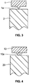
- FIG. 2 is a cross-sectional view of the parts in position for welding, where the tip of the energy director of part 1 is in contact with the flat surface of part 2.
- FIG. 3 is an enlarged view of the energy director area of the section view of FIG. 2 .
- the tip of the energy director is either sharp or slightly radiused, so as to provide a small contact area between the parts, allowing the ultrasonic vibrations to be focused at the beginning of the weld to initiate melting.
- the triangular energy director generally referred to in the industry as simply "energy director,” and its applications are detailed in a number of technical publications, such as the " Handbook of Plastic Joining" (Second Edition, Edited by Michael J. Trought on).
- the triangular energy director design has been in commercial use for many years, several undesirable characteristics are associated with this joint shape.
- One of the most significant factors is the high manufacturing cost of the part mold containing the energy director.
- the energy director geometry is typically produced by either electrical discharge machining (EDM) on a single piece of steel, or splitting the mold into two pieces along the center of the energy director with a closely controlled gap between them.
- EDM electrical discharge machining
- the former technique is time-consuming and involves dedicated tooling, and the latter requires tight machining tolerances. Consequently, the cost of mold fabrication is relatively high.
- Another disadvantage is the challenge in molding parts with energy directors. Specifically, it can be difficult to completely fill the sharp tip with plastic during the molding process.
- Incomplete or inconsistent energy directors can in turn lead to weaker ultrasonic welds, or welds that are not uniform along the entire joint path.
- Still another drawback is the susceptibility of the energy director to being damaged prior to welding. After the plastic parts are molded, they are often packaged in bulk and transported to the welding station. If the packaging method permits the energy directors to come in contact with other parts, the energy director rib can be distorted or crushed, sometimes in a highly localized manner. Flaws of this type can result in areas where there is an insufficient amount of material to produce a continuous weld, which is especially problematic in cases where a hermetic seal is required.
- An ultrasonic welding method for joining first and second thermoplastic parts according to the preamble of independent claim 1 is known, for example, from GB 1047295 A .
- An ultrasonic welding method for joining a film or fabric to a rigid thermoplastic part according to the preamble of independent claim 8 is known, for example, from EP 2202117 A1 .
- a method according to the invention is defined by independent claim 1 and by independent claim 8.
- an ultrasonic welding method for joining first and second thermoplastic parts.
- At least one energy director is formed on at least one surface of the first thermoplastic part, with the energy director projecting from the surface of the first thermoplastic part toward an opposed surface of the second thermoplastic part.
- the distal end portion of the energy director has a curved surface that initially engages the opposed surface of the second thermoplastic part when the first and second parts are brought into engagement with each other.
- the first and second thermoplastic parts are ultrasonically welded by pressing the parts together while vibrating at least the first part in a direction parallel to the direction of projection of the energy director.
- a longitudinal section taken through the energy director, in a direction normal to the surface to be engaged by the director has a curved profile at the distal end of the director.
- the curved profile may be a section of a circle having a center that is substantially coincident with the surface of said first thermoplastic part from which the energy director protrudes, or spaced away from the surface of the first thermoplastic part from which the energy director protrudes, either in a direction opposite the direction of projection of the energy director or in the same direction as the direction of projection of the energy director.
- a pair of substantially flat side walls may be joined to opposite ends of the curved profile, with the side walls diverging from each other as they extend away from the curved profile toward the surface of the thermoplastic part on which the energy director is formed.
- the maximum width of the curved profile is preferably at least half of the maximum width of the longitudinal section taken through the energy director.
- the curved profile has a radius of curvature of at least 0.20 mm. at the distal end of the energy director.
- the ultrasonic welding method for joining the first and second thermoplastic parts in accordance with claim 1 comprises forming at least one energy director on at least one surface of the first thermoplastic part, the energy director projecting from the surface of the first thermoplastic part toward an opposed surface of the second thermoplastic part, the end portion of the energy director having a curved or flat surface that initially engages the opposed surface when the first and second thermoplastic parts are brought into engagement with each other, and ultrasonically welding the first and second thermoplastic parts by pressing the parts together while vibrating at least the first part in a direction parallel to the direction of projection of the energy director.
- the energy director is preferably formed in a mold in which the cavity that forms the energy director is formed by ball end milling.
- the ultrasonic welding method for joining a film or fabric to a rigid thermoplastic part in accordance with claim 8 comprises forming at least one energy director on at least one surface of a rigid thermoplastic part, with the energy director projecting from the surface of the rigid thermoplastic part toward an opposed film or fabric, the end portion of the energy director having a curved surface that initially engages the film or fabric when the film or fabric is brought into engagement with the rigid thermoplastic part; and ultrasonically welding the film or fabric to the rigid thermoplastic part by pressing the film or fabric and the rigid thermoplastic part together while vibrating at least one of the rigid thermoplastic part or the film or fabric in a direction parallel to the direction of projection of the energy director.
- a first plastic part 10 containing an energy director 10a is to be welded to a second plastic part 20.
- the energy director 10a projecting from the first part 10 has a curved profile at the distal end of the director.
- the curved profile has a semi-circular shape, with the center of the circle substantially coincident with the surface of the first thermoplastic part 10 from which the energy director 10a protrudes.
- the center of the circle can be offset (spaced away) from the surface of the first thermoplastic part from which said energy director protrudes.
- the center of the circle of the energy director 10b is offset in a direction opposite the direction of projection of said energy director by a distance X.
- the center of the circle of the energy director 10c is offset in a direction opposite the direction of projection of said energy director by a distance Y and the profile of the energy director 10c additionally includes flat, tapered sides emanating from the flat surface of the part 10 and terminating tangentially at the generally semi-circular section of the distal end portion of the energy director.
- the diameter of the semi-circular portion of the profile of the energy director is preferably at least one-half of the width of the energy director in the plane of the flat part surface from which energy director emanates.
- FIG. 5C which shows an energy director not in accordance with the invention
- the energy director 10d has a trapezoidal cross-section profile, forming a flat surface on the distal end of the energy director.
- FIG. 5D which shows an energy director not in accordance with the invention illustrates a modified version of the energy director shown in FIG. 5C , in which the corners of the trapezoid at the distal end of the energy director 1 0e are truncated, forming a pair of beveled surfaces.
- the energy director with the curved or flat distal end profile is suitable for use with the same wide variety of part geometries as previous energy directors.
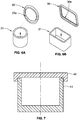
- Example designs of simple parts containing the round energy director joint are illustrated in FIG. 6 , where FIG. 6A shows parts 20, 21 with a circular joint path 20a, and FIG. 6B shows parts 30, 31 with a rectangular joint path 30a. In both configurations, the energy director in the joint path is integral to the first part 20 or 30, with the second part 21 or 31 containing the flat mating surface.
- FIG. 7 is a cross-sectional view of FIG. 6A , showing the parts in position for welding, where the tip of the energy director of part 40 is in contact with the flat surface of part 41.
- the energy director with the curved or flat distal end profile offers a number of advantages compared to the triangular design.
- the time and expense of fabricating the mold are significantly reduced.
- the energy director with the curved or flat distal end profile can be directly milled into a single piece of steel using standard ball end mills, which eliminates the need for special tooling or very tight machining tolerances.
- the energy director with the curved or flat distal end profile permits the use of cutting tools with larger diameters, reducing machining time and spindle rotational speed requirements of the machine tool.
- the part molding process is facilitated by the fact that molten plastic will fill the cavity of the energy director with the curved or flat distal end profile more readily than the tip of the triangular energy director, leading to improvements in weld joint uniformity and part-to-part consistency, and ultimately resulting in more uniform and consistent weld results.
- the energy director with the curved or flat distal end profile is more robust than a comparably-sized triangular energy director and therefore less prone to damage when parts are handled, packaged and transported between the time when they are molded and the time when they are welded. With a smaller risk of compromising the energy director, especially at its tip, production yields can be improved.
- the cap (part 1 in FIG. 1 ) contained an energy director having the profile illustrated in FIG. 4 , with a tip radius of 0.41 mm.
- the cap contained a triangular energy director as shown in FIG. 3 , with a height of 0.38 mm and a tip angle of 90°.
- the base (part 2 in FIG. 1 ) was identical in both sets.
- the round energy directors described above are also useful for welding a film or fabric to the rigid thermoplastic part on which the energy director is formed.
- the film or fabric is typically positioned for ultrasonic welding by being placed in tension directly over the rigid thermoplastic part on which the round energy director is formed.
- the film or fabric can be supported on a surface that does not adhere to the rigid thermoplastic part on which the energy director is formed. Ultrasonic vibrations emanating from the horn (sonotrode) for welding the film or fabric to the rigid part can be applied to either the film side or the rigid part side.
Landscapes
- Engineering & Computer Science (AREA)
- Mechanical Engineering (AREA)
- Lining Or Joining Of Plastics Or The Like (AREA)
- Pressure Welding/Diffusion-Bonding (AREA)
Description
- This invention relates to ultrasonic welding of thermoplastics, particularly to an ultrasonic welding method for joining first and second thermoplastic parts according to the preamble of
independent claim 1 and to an ultrasonic welding method for joining a film or fabric to a rigid thermoplastic part according to the preamble of independent claim 8. - One of the commonly used methods for joining thermoplastic parts is ultrasonic welding, which involves melting of the mating part surfaces by means of highfrequency, small-amplitude vibrations while the parts are pressed together. When a sufficient amount of melting has occurred, the ultrasonic vibrations are terminated and the plastic solidifies while the compressive force on the parts is maintained, producing a permanent assembly. Ultrasonic welding offers a number of advantages over other joining methods, including speed, flexibility, cleanliness, and low cost.
- A key consideration in the successful use of ultrasonic welding is the design of the weld joint; namely, the geometries of those areas of the parts to be joined which are melted during the welding process. A number of different weld joint designs are known to those skilled in the art, each suited for the purpose of meeting specific weld criteria or to facilitate welding of certain materials.
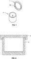
- One of the most commonly used weld joint designs is the triangular energy director, consisting of a ridge of material having a triangular profile on one of the parts and a flat surface on the mating part. This joint design is illustrated in the example of
FIGs. 1-3 .FIG. 1 shows the two parts, withpart 1 containing the energy director la andpart 2 containing the flat surface.FIG. 2 is a cross-sectional view of the parts in position for welding, where the tip of the energy director ofpart 1 is in contact with the flat surface ofpart 2.FIG. 3 is an enlarged view of the energy director area of the section view ofFIG. 2 . The tip of the energy director is either sharp or slightly radiused, so as to provide a small contact area between the parts, allowing the ultrasonic vibrations to be focused at the beginning of the weld to initiate melting. The triangular energy director, generally referred to in the industry as simply "energy director," and its applications are detailed in a number of technical publications, such as the "Handbook of Plastic Joining" (Second Edition, Edited by Michael J. Troughton). - While the triangular energy director design has been in commercial use for many years, several undesirable characteristics are associated with this joint shape. One of the most significant factors is the high manufacturing cost of the part mold containing the energy director. In order to create the sharp edge at the tip, the energy director geometry is typically produced by either electrical discharge machining (EDM) on a single piece of steel, or splitting the mold into two pieces along the center of the energy director with a closely controlled gap between them. The former technique is time-consuming and involves dedicated tooling, and the latter requires tight machining tolerances. Consequently, the cost of mold fabrication is relatively high. Another disadvantage is the challenge in molding parts with energy directors. Specifically, it can be difficult to completely fill the sharp tip with plastic during the molding process. Incomplete or inconsistent energy directors can in turn lead to weaker ultrasonic welds, or welds that are not uniform along the entire joint path. Still another drawback is the susceptibility of the energy director to being damaged prior to welding. After the plastic parts are molded, they are often packaged in bulk and transported to the welding station. If the packaging method permits the energy directors to come in contact with other parts, the energy director rib can be distorted or crushed, sometimes in a highly localized manner. Flaws of this type can result in areas where there is an insufficient amount of material to produce a continuous weld, which is especially problematic in cases where a hermetic seal is required.
- An ultrasonic welding method for joining first and second thermoplastic parts according to the preamble of
independent claim 1 is known, for example, fromGB 1047295 A EP 2202117 A1 . Further related prior art is known fromCN 201064946 Y ,US 2011/174423 A1 ,EP 0661208 A1 ,DE 102010003268 A1 ,WO 2006/128246 A1 ,EP 1072391 A2 ,WO 2013/053588 A1 ,JP S5916495 A EP 0168750 A1 , and from the article "Effects of dimensions of the gap between the edges on the strength of ultrasound welded joints in rigid plastics", Welding International, Taylor & Francis, Abingdon, GB, vol. 17, no. 6, 1 January 2003 (2003-01-01), pages 482-486, XP001167971, ISSN: 0950-7116, DOI: 10.1533/WINT.2003.3154. - A method according to the invention is defined by
independent claim 1 and by independent claim 8. - In accordance with one embodiment, an ultrasonic welding method is provided for joining first and second thermoplastic parts. At least one energy director is formed on at least one surface of the first thermoplastic part, with the energy director projecting from the surface of the first thermoplastic part toward an opposed surface of the second thermoplastic part. The distal end portion of the energy director has a curved surface that initially engages the opposed surface of the second thermoplastic part when the first and second parts are brought into engagement with each other. The first and second thermoplastic parts are ultrasonically welded by pressing the parts together while vibrating at least the first part in a direction parallel to the direction of projection of the energy director.
- According to the invention, a longitudinal section taken through the energy director, in a direction normal to the surface to be engaged by the director, has a curved profile at the distal end of the director. For example, the curved profile may be a section of a circle having a center that is substantially coincident with the surface of said first thermoplastic part from which the energy director protrudes, or spaced away from the surface of the first thermoplastic part from which the energy director protrudes, either in a direction opposite the direction of projection of the energy director or in the same direction as the direction of projection of the energy director. A pair of substantially flat side walls may be joined to opposite ends of the curved profile, with the side walls diverging from each other as they extend away from the curved profile toward the surface of the thermoplastic part on which the energy director is formed. The maximum width of the curved profile is preferably at least half of the maximum width of the longitudinal section taken through the energy director. According to the invention, the curved profile has a radius of curvature of at least 0.20 mm. at the distal end of the energy director.
- The ultrasonic welding method for joining the first and second thermoplastic parts in accordance with
claim 1, comprises forming at least one energy director on at least one surface of the first thermoplastic part, the energy director projecting from the surface of the first thermoplastic part toward an opposed surface of the second thermoplastic part, the end portion of the energy director having a curved or flat surface that initially engages the opposed surface when the first and second thermoplastic parts are brought into engagement with each other, and ultrasonically welding the first and second thermoplastic parts by pressing the parts together while vibrating at least the first part in a direction parallel to the direction of projection of the energy director. - The energy director is preferably formed in a mold in which the cavity that forms the energy director is formed by ball end milling.
- The ultrasonic welding method for joining a film or fabric to a rigid thermoplastic part in accordance with claim 8 comprises forming at least one energy director on at least one surface of a rigid thermoplastic part, with the energy director projecting from the surface of the rigid thermoplastic part toward an opposed film or fabric, the end portion of the energy director having a curved surface that initially engages the film or fabric when the film or fabric is brought into engagement with the rigid thermoplastic part; and ultrasonically welding the film or fabric to the rigid thermoplastic part by pressing the film or fabric and the rigid thermoplastic part together while vibrating at least one of the rigid thermoplastic part or the film or fabric in a direction parallel to the direction of projection of the energy director.
- The invention may best be understood by reference to the following description taken in conjunction with the accompanying drawings, in which:
-
FIG. 1 is an exploded perspective view of parts for ultrasonic welding, one of which contains a triangular energy director. -
FIG. 2 is an enlarged sectional view of the parts ofFIG. 1 positioned for ultrasonic welding. -
FIG. 3 is a further enlarged sectional view of those portions of the parts ofFIG. 2 . -
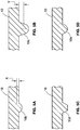
FIG. 4 is a sectional view of parts containing a round energy director, where the center of the energy director circular section is coincident with the part surface from which it protrudes. -
FIG. 5A and FIG. 5B are sectional views of parts containing energy directors having round distal end surfaces that are sections of a circle having a center that is either recessed below the part surface from which the energy director protrudes (FIG. 5A ) or is extended forward of the part surface on which the energy director is formed (FIG. 5B ). -
FIG. 5C and FIG. 5D are sectional views of parts having energy directors with flat distal ends, where the flat end surface of the energy director terminates at either a pair of side walls that diverge from each other as they extend toward the surface of the part on which the energy director is formed (FIG. 5C ), or at a pair of beveled corners that merge with a pair of side walls that diverge from each other as they extend toward the surface of the part on which the energy director is formed -
FIGs. 6A and 6B are a pair of exploded perspective views of parts containing the round energy directors. -
FIG. 7 is a cross-sectional view of the parts ofFIG. 6A . -
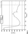
FIG. 8 is a pair of graphs of Distance vs. Time for two representative samples welded during an experiment comparing the weld quality of parts containing a round energy director to those containing a triangular energy director. -
FIG. 9 is a pair of graphs of Force vs. Time for the samples noted inFIG. 8 . -
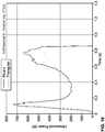
FIG. 10 is a pair of graphs of Ultrasound Power vs. Time for the samples noted inFIG. 8 . - While the present disclosure is susceptible to various modifications and alternative forms, specific embodiments or implementations have been shown by way of example in the drawings and will be described in detail herein. It should be understood, however, that the disclosure is not intended to be limited to the particular forms disclosed. Rather, the disclosure is to cover all modifications, equivalents, and alternatives falling within the scope of the invention as defined by the appended claims.
- Although the invention will be described in connection with certain preferred embodiments, it will be understood that the invention is not limited to those particular embodiments. On the contrary, the invention is intended to cover all alternatives, modifications, and equivalent arrangements as may be included within the scope of the invention as defined by the appended claims.
- In the sectional view in
FIG. 4 , a firstplastic part 10 containing anenergy director 10a is to be welded to a secondplastic part 20. In this embodiment, theenergy director 10a projecting from thefirst part 10 has a curved profile at the distal end of the director. In this example, the curved profile has a semi-circular shape, with the center of the circle substantially coincident with the surface of the firstthermoplastic part 10 from which theenergy director 10a protrudes. Alternatively, the center of the circle can be offset (spaced away) from the surface of the first thermoplastic part from which said energy director protrudes. InFIG. 5A , the center of the circle of theenergy director 10b is offset in a direction opposite the direction of projection of said energy director by a distance X. InFIG. 5B , the center of the circle of theenergy director 10c is offset in a direction opposite the direction of projection of said energy director by a distance Y and the profile of theenergy director 10c additionally includes flat, tapered sides emanating from the flat surface of thepart 10 and terminating tangentially at the generally semi-circular section of the distal end portion of the energy director. The diameter of the semi-circular portion of the profile of the energy director is preferably at least one-half of the width of the energy director in the plane of the flat part surface from which energy director emanates. Although in the illustrated embodiments the surfaces of thepart 10 adjacent the energy directors are flat surfaces, it will be understood that those adjacent part surfaces could be non-flat surfaces. - In
FIG. 5C which shows an energy director not in accordance with the invention, theenergy director 10d has a trapezoidal cross-section profile, forming a flat surface on the distal end of the energy director.FIG. 5D which shows an energy director not in accordance with the invention illustrates a modified version of the energy director shown inFIG. 5C , in which the corners of the trapezoid at the distal end of theenergy director 1 0e are truncated, forming a pair of beveled surfaces. - The energy director with the curved or flat distal end profile is suitable for use with the same wide variety of part geometries as previous energy directors. Example designs of simple parts containing the round energy director joint are illustrated in
FIG. 6 , whereFIG. 6A showsparts joint path 20a, andFIG. 6B showsparts joint path 30a. In both configurations, the energy director in the joint path is integral to thefirst part second part -
FIG. 7 is a cross-sectional view ofFIG. 6A , showing the parts in position for welding, where the tip of the energy director ofpart 40 is in contact with the flat surface ofpart 41. AlthoughFIG. 6 and FIG. 7 depict the energy director as being integral to the first part, it can alternatively be incorporated into the second part, with the first part containing the flat surface. - While preserving the characteristic of providing a small contact area between the parts as the weld is initiated, the energy director with the curved or flat distal end profile offers a number of advantages compared to the triangular design. First, the time and expense of fabricating the mold are significantly reduced. The energy director with the curved or flat distal end profile can be directly milled into a single piece of steel using standard ball end mills, which eliminates the need for special tooling or very tight machining tolerances. In addition, the energy director with the curved or flat distal end profile permits the use of cutting tools with larger diameters, reducing machining time and spindle rotational speed requirements of the machine tool. Second, the part molding process is facilitated by the fact that molten plastic will fill the cavity of the energy director with the curved or flat distal end profile more readily than the tip of the triangular energy director, leading to improvements in weld joint uniformity and part-to-part consistency, and ultimately resulting in more uniform and consistent weld results. Third, the energy director with the curved or flat distal end profile is more robust than a comparably-sized triangular energy director and therefore less prone to damage when parts are handled, packaged and transported between the time when they are molded and the time when they are welded. With a smaller risk of compromising the energy director, especially at its tip, production yields can be improved.
- The benefits of the energy director with the curved or flat distal end profile with regard to weld quality have been confirmed by an experiment consisting of welding two sets of round polycarbonate samples similar to the parts shown in
FIG. 1 . In the first set, the cap (part 1 inFIG. 1 ) contained an energy director having the profile illustrated inFIG. 4 , with a tip radius of 0.41 mm. In the second set, the cap contained a triangular energy director as shown inFIG. 3 , with a height of 0.38 mm and a tip angle of 90°. The base (part 2 inFIG. 1 ) was identical in both sets. Using a servo-driven ultrasonic press of the type described inU.S. Patent No. 7,819,158 and employing the delayed motion technique described inU.S. Patent No. 8,052,816 , welding parameters were determined for each sample set to yield optimum weld strength (i.e., tensile failure load) while maintaining the same weld collapse distance. Using the optimized parameters for each set, a statistically significant number of samples was welded and subsequently pull-tested to measure the weld strength. For the first energy director set, the average weld strength and its standard deviation expressed as a percentage of the average were 5220 N and 5.8 %, respectively, whereas for the triangular energy director set, the results were 4770 N and 10.6 %, respectively, -
FIGs. 8-10 are graphs of several parameters for representative samples welded in the above experiment, whereFIG. 8 shows Distance vs. Time,FIG. 9 shows Force vs. Time, andFIG. 10 shows Ultrasound Power vs. Time, for one sample containing the energy director with the round end profile and one sample containing the triangular energy director. On each graph, the ultrasound vibrations were initiated at Time = 0 s. - The results of this experiment confirm that an energy director in accordance with the present invention yields more consistent results and higher weld strengths. It should be noted that a servo-driven ultrasonic press employing the aforementioned delayed motion technique is particularly well-suited for welding parts with the energy director with the curved or flat distal end profile, due to its ability to suspend motion until initial melting of the plastic material occurs as well as to change forces rapidly during the weld process.
- The round energy directors described above are also useful for welding a film or fabric to the rigid thermoplastic part on which the energy director is formed. (Welding film to rigid plastic is popular in the packaging industry.) The film or fabric is typically positioned for ultrasonic welding by being placed in tension directly over the rigid thermoplastic part on which the round energy director is formed. Alternatively, the film or fabric can be supported on a surface that does not adhere to the rigid thermoplastic part on which the energy director is formed. Ultrasonic vibrations emanating from the horn (sonotrode) for welding the film or fabric to the rigid part can be applied to either the film side or the rigid part side.
- While particular implementations and applications of the present disclosure have been illustrated and described, it is to be understood that the present disclosure is not limited to the precise construction and compositions disclosed herein and that various modifications, changes, and variations can be apparent from the foregoing descriptions without departing from the scope of the invention as defined in the appended claims.
Claims (9)
- An ultrasonic welding method for joining first and second thermoplastic parts, said method comprising
forming at least one energy director on at least one surface of said first thermoplastic part, said energy director projecting from said surface of said first thermoplastic part toward an opposed surface of said second thermoplastic part, the end portion of said energy director having a curved surface that initially engages said opposed surface when said first and second thermoplastic parts are brought into engagement with each other, wherein a longitudinal section taken through said energy director, in a direction normal to the surface to be engaged by said director, has a curved profile at a distal end of said director, and
ultrasonically welding said first and second thermoplastic parts by pressing the parts together while vibrating at least said first part in a direction parallel to the direction of projection of said energy director,
characterized in that said curved profile has a radius of curvature of at least 0.20 mm at the distal end of said energy director, wherein the parts are pressed together using a servo-driven ultrasonic press employing a delayed motion technique in which motion is suspended until initial melting of plastic material occurs and forces are changed rapidly during the weld process. - The ultrasonic welding method of claim 1, in which said curved profile is a section of a circle.
- The ultrasonic welding method of claim 2, in which the center of said circle is substantially coincident with the surface of said first thermoplastic part from which said energy director protrudes.
- The ultrasonic welding method of claim 2, in which the center of said circle is spaced away from the surface of said first thermoplastic part from which said energy director protrudes, in a direction opposite the direction of projection of said energy director.
- The ultrasonic welding method of claim 2, in which the center of said circle is spaced away from the surface of said first thermoplastic part from which said energy director protrudes, in the same direction as the direction of projection of said energy director, and which includes a pair of substantially flat side walls joined to opposite ends of said curved profile, said substantially flat side walls diverging from each other as they extend away from said curved profile toward the surface of said first thermoplastic part to be joined to said second thermoplastic part.
- The ultrasonic welding method of claim 1, in which the maximum width of said curved profile is at least half of the maximum width of said longitudinal section taken through said energy director.
- The ultrasonic welding method of claim 1, in which said energy director is formed in a mold in which the cavity that forms said energy director is formed by ball end milling.
- An ultrasonic welding method for joining a film or fabric to a rigid thermoplastic part, said method comprising
forming at least one energy director on at least one surface of said rigid thermoplastic part, said energy director projecting from said surface of said rigid thermoplastic part toward an opposed surface of said film or fabric, the end portion of said energy director having a curved surface that initially engages said film or fabric when said film or fabric is brought into engagement with said rigid thermoplastic part, wherein a longitudinal section taken through said energy director, in a direction normal to the surface to be engaged by said director, has a curved profile at a distal end of said director, and
ultrasonically welding said film or fabric to said rigid thermoplastic part by pressing said film or fabric and said rigid thermoplastic part together while vibrating at least said rigid thermoplastic part or said film or fabric in a direction parallel to the direction of projection of said energy director
characterized in that said curved profile has a radius of curvature of at least 0.20 mm at the distal end of said energy director, wherein said film or fabric and said rigid thermoplastic part are pressed together using a servo-driven ultrasonic press employing a delayed motion technique in which motion is suspended until initial melting of plastic material occurs and forces are changed rapidly during the weld process. - The method of claim 8, in which said film or fabric is supported on a rigid surface made of a material that will not adhere to said rigid thermoplastic part.
Priority Applications (1)
| Application Number | Priority Date | Filing Date | Title |
|---|---|---|---|
| PL14861847T PL3068604T3 (en) | 2013-11-12 | 2014-09-29 | Method for ultrasonic welding of thermoplastics parts |
Applications Claiming Priority (2)
| Application Number | Priority Date | Filing Date | Title |
|---|---|---|---|
| US201361902830P | 2013-11-12 | 2013-11-12 | |
| PCT/US2014/058027 WO2015073126A1 (en) | 2013-11-12 | 2014-09-29 | Energy director joint design for ultrasonic welding of thermoplastics |
Publications (3)
| Publication Number | Publication Date |
|---|---|
| EP3068604A1 EP3068604A1 (en) | 2016-09-21 |
| EP3068604A4 EP3068604A4 (en) | 2017-07-19 |
| EP3068604B1 true EP3068604B1 (en) | 2019-09-18 |
Family
ID=53042656
Family Applications (1)
| Application Number | Title | Priority Date | Filing Date |
|---|---|---|---|
| EP14861847.3A Active EP3068604B1 (en) | 2013-11-12 | 2014-09-29 | Method for ultrasonic welding of thermoplastics parts |
Country Status (7)
| Country | Link |
|---|---|
| US (1) | US9873225B2 (en) |
| EP (1) | EP3068604B1 (en) |
| JP (1) | JP6661535B2 (en) |
| CN (1) | CN105916658B (en) |
| ES (1) | ES2750616T3 (en) |
| PL (1) | PL3068604T3 (en) |
| WO (1) | WO2015073126A1 (en) |
Families Citing this family (9)
| Publication number | Priority date | Publication date | Assignee | Title |
|---|---|---|---|---|
| CA3001775A1 (en) * | 2015-12-02 | 2017-06-08 | Swedish Match North Europe Ab | Sealing device |
| US20170355150A1 (en) | 2016-06-14 | 2017-12-14 | GM Global Technology Operations LLC | Ultrasonic weld-bonding of thermoplastic composites |
| US10265913B2 (en) | 2016-11-23 | 2019-04-23 | GM Global Technology Operations LLC | Horn for an ultrasonic welding process |
| US10913211B2 (en) | 2017-05-30 | 2021-02-09 | Campbell Soup Company | High rate ultrasonic sealer |
| CN107364144A (en) * | 2017-08-18 | 2017-11-21 | 上海小糸车灯有限公司 | Ultrasonic Plastic Welding method and the plastics welding structure for realizing this method |
| WO2019164410A1 (en) * | 2018-02-26 | 2019-08-29 | Argenta Innovation Limited | Intra-ruminal device |
| CZ35004U1 (en) | 2020-06-18 | 2021-04-20 | Radim Ing. Žďárský | Ultrasonic welding unit |
| CN214092344U (en) * | 2020-11-27 | 2021-08-31 | 瑞声光电科技(常州)有限公司 | Miniature water pump |
| US11949197B2 (en) | 2021-03-15 | 2024-04-02 | Ideal Industries, Inc. | Methods and systems for joining workpieces |
Family Cites Families (25)
| Publication number | Priority date | Publication date | Assignee | Title |
|---|---|---|---|---|
| GB1047295A (en) | 1900-01-01 | |||
| US3850776A (en) * | 1971-12-07 | 1974-11-26 | E Karobath | Apparatus for joining a tubular thermoplastic container jacket, by means of ultrasonics to a thermoplastic end cap to form a liquid-tight seal |
| JPS5916495A (en) | 1982-07-19 | 1984-01-27 | Sanyo Electric Co Ltd | Joining method of speaker diaphragm and edge |
| FR2567674B1 (en) | 1984-07-10 | 1987-01-16 | Thomson Alcatel Gigadisc | PROTECTED OPTICAL DISC WITH WELDED ELEMENTS |
| JPS63278821A (en) * | 1987-05-11 | 1988-11-16 | Izumi Kogyo Kk | Method for joining small part on synthetic resin product |
| DE3929710A1 (en) * | 1989-09-07 | 1991-03-14 | Mosca G Maschf | Ultrasonically sealing packages in film - machine draws plastic film over top front and bottom of packages, presses film round rear and underside, and applies sonotrode underneath |
| US5393360A (en) * | 1993-10-06 | 1995-02-28 | The Procter & Gamble Company | Method and apparatus for combining a tensioned elastic garter with a substrate |
| US5606844A (en) | 1993-12-27 | 1997-03-04 | Sumitomo Bakelite Company, Limited | Process for producing a self-supporting package having an outlet stopper and an apparatus for producing said package |
| JPH07266424A (en) * | 1994-03-28 | 1995-10-17 | Ota Sheet:Kk | Method for ornamenting synthetic resin base material |
| JP3078231B2 (en) * | 1995-08-22 | 2000-08-21 | 株式会社アルテクス | Ultrasonic vibration bonding equipment |
| JP3427247B2 (en) * | 1997-06-17 | 2003-07-14 | 豊田合成株式会社 | Soundproof material |
| JP3697080B2 (en) * | 1998-09-21 | 2005-09-21 | テルモ株式会社 | Probe cover manufacturing method and probe cover |
| JP2001030359A (en) | 1999-07-27 | 2001-02-06 | Nippon Pop Rivets & Fasteners Ltd | Bonding method for plastic clip, and plastic clip |
| JP2006179154A (en) * | 2004-12-24 | 2006-07-06 | Fuji Photo Film Co Ltd | Cartridge for photosensitive recording medium |
| JP4590453B2 (en) | 2005-06-03 | 2010-12-01 | ラパック、アジア、パシフィック、リミテッド | Sealable container and method for sealing a container |
| FR2887800B1 (en) * | 2005-07-04 | 2011-02-11 | Eads Ccr Groupement Dinteret Economique | ULTRASONIC ASSEMBLY METHOD OF AT LEAST TWO RIGID PIECES |
| US8052816B2 (en) * | 2006-05-08 | 2011-11-08 | Dukane Corporation | Ultrasonic press using servo motor with delayed motion |
| EP2133191A4 (en) | 2007-03-02 | 2013-05-15 | Compania Espanola De Ultrasonidos Sa | Ultrasonic head and transducer for ultrasonic soldering of plastics |
| CN201064946Y (en) | 2007-06-07 | 2008-05-28 | 比亚迪股份有限公司 | Ultrasonic line structure for welding plastic piece |
| US8727844B2 (en) | 2007-09-04 | 2014-05-20 | Nitto Denko Corporation | Ventilation member and method of manufacturing the same |
| US8714402B2 (en) | 2010-01-21 | 2014-05-06 | General Mills, Inc. | Thermoformed container assembly for food products |
| DE102010003268A1 (en) | 2010-03-18 | 2011-09-22 | Robert Bosch Gmbh | Plastic closure device for tubular bags |
| DE102011006506B4 (en) | 2010-11-02 | 2013-11-07 | Rovema Gmbh | Ultrasonic heat sealing with seal pressure control |
| US8360300B1 (en) * | 2011-09-30 | 2013-01-29 | Infineon Technologies Ag | Method and apparatus for ultrasonic welding |
| DE102011084508B4 (en) | 2011-10-14 | 2022-03-03 | Syntegon Pouch Systems Ag | Plastic closure device for a tubular bag |
-
2014
- 2014-09-29 WO PCT/US2014/058027 patent/WO2015073126A1/en active Application Filing
- 2014-09-29 EP EP14861847.3A patent/EP3068604B1/en active Active
- 2014-09-29 ES ES14861847T patent/ES2750616T3/en active Active
- 2014-09-29 CN CN201480060659.4A patent/CN105916658B/en active Active
- 2014-09-29 JP JP2016530018A patent/JP6661535B2/en active Active
- 2014-09-29 PL PL14861847T patent/PL3068604T3/en unknown
- 2014-09-29 US US14/500,416 patent/US9873225B2/en active Active
Non-Patent Citations (1)
| Title |
|---|
| None * |
Also Published As
| Publication number | Publication date |
|---|---|
| US20150129110A1 (en) | 2015-05-14 |
| ES2750616T3 (en) | 2020-03-26 |
| US9873225B2 (en) | 2018-01-23 |
| CN105916658B (en) | 2019-09-13 |
| CN105916658A (en) | 2016-08-31 |
| PL3068604T3 (en) | 2019-12-31 |
| JP6661535B2 (en) | 2020-03-11 |
| JP2017501901A (en) | 2017-01-19 |
| EP3068604A4 (en) | 2017-07-19 |
| EP3068604A1 (en) | 2016-09-21 |
| WO2015073126A1 (en) | 2015-05-21 |
Similar Documents
| Publication | Publication Date | Title |
|---|---|---|
| EP3068604B1 (en) | Method for ultrasonic welding of thermoplastics parts | |
| US20070057015A1 (en) | Tapered friction stir welding and processing tool | |
| KR20000022315A (en) | Simultaneous amplitude and force profiling during ultrasonic welding of thermoplastic workpieces | |
| US7419082B2 (en) | Friction welding process | |
| US4451721A (en) | Method for high frequency welding flangeless thermoplastic shells | |
| US20140203067A1 (en) | Welding Tool Comprising a Shoulder, Welding Method and Workpiece | |
| US20030219602A1 (en) | Ultrasonic joining of thermoplastic parts | |
| KR101036884B1 (en) | Projection welding nut and manufacturing method thereof | |
| US20100307660A1 (en) | Device and Method for Ultrasonic Treatment | |
| JP2009185951A (en) | Method of processing joint of belt | |
| US11949197B2 (en) | Methods and systems for joining workpieces | |
| TWI687273B (en) | Diffuser for fluid-operated pump and method of manufacturing the same | |
| KR20170118046A (en) | Tooling for ultrasonic tube sealer for sealing an end portion of a tube to have a rounded configuration | |
| JP2893808B2 (en) | Method of continuous welding and cutting of plastic sheet | |
| JP3157258U (en) | Resin ball chain welding and bonding equipment | |
| JP4759581B2 (en) | Belt joint processing method | |
| US20210114173A1 (en) | Blade-like polisher and its manufacturing method | |
| JP5019245B2 (en) | Manufacturing method of composite member | |
| KR101664587B1 (en) | Plated steel welding method | |
| Bongo | Ultrasonic Assembly of Thermoplastics | |
| KR200275376Y1 (en) | A bondface-heater for manufactoring equipment of plasticboard-box | |
| JP2598295B2 (en) | Method of forming a polygonal flange at the end of a resin pipe | |
| JP2021178342A (en) | Joint fixing method and joint fixing structure of pipe diagonal material | |
| JP4962611B2 (en) | Resin-welded core, composite member and manufacturing method thereof | |
| JP2010083068A (en) | Welding structure, welded body, and creep-rapture life improvement method |
Legal Events
| Date | Code | Title | Description |
|---|---|---|---|
| PUAI | Public reference made under article 153(3) epc to a published international application that has entered the european phase |
Free format text: ORIGINAL CODE: 0009012 |
|
| 17P | Request for examination filed |
Effective date: 20160422 |
|
| AK | Designated contracting states |
Kind code of ref document: A1 Designated state(s): AL AT BE BG CH CY CZ DE DK EE ES FI FR GB GR HR HU IE IS IT LI LT LU LV MC MK MT NL NO PL PT RO RS SE SI SK SM TR |
|
| AX | Request for extension of the european patent |
Extension state: BA ME |
|
| DAX | Request for extension of the european patent (deleted) | ||
| A4 | Supplementary search report drawn up and despatched |
Effective date: 20170619 |
|
| RIC1 | Information provided on ipc code assigned before grant |
Ipc: B29C 65/08 20060101AFI20170612BHEP Ipc: B32B 37/02 20060101ALI20170612BHEP |
|
| GRAP | Despatch of communication of intention to grant a patent |
Free format text: ORIGINAL CODE: EPIDOSNIGR1 |
|
| STAA | Information on the status of an ep patent application or granted ep patent |
Free format text: STATUS: GRANT OF PATENT IS INTENDED |
|
| INTG | Intention to grant announced |
Effective date: 20190408 |
|
| GRAS | Grant fee paid |
Free format text: ORIGINAL CODE: EPIDOSNIGR3 |
|
| GRAA | (expected) grant |
Free format text: ORIGINAL CODE: 0009210 |
|
| STAA | Information on the status of an ep patent application or granted ep patent |
Free format text: STATUS: THE PATENT HAS BEEN GRANTED |
|
| AK | Designated contracting states |
Kind code of ref document: B1 Designated state(s): AL AT BE BG CH CY CZ DE DK EE ES FI FR GB GR HR HU IE IS IT LI LT LU LV MC MK MT NL NO PL PT RO RS SE SI SK SM TR |
|
| REG | Reference to a national code |
Ref country code: GB Ref legal event code: FG4D |
|
| REG | Reference to a national code |
Ref country code: CH Ref legal event code: EP |
|
| REG | Reference to a national code |
Ref country code: DE Ref legal event code: R096 Ref document number: 602014054025 Country of ref document: DE |
|
| REG | Reference to a national code |
Ref country code: AT Ref legal event code: REF Ref document number: 1180774 Country of ref document: AT Kind code of ref document: T Effective date: 20191015 |
|
| REG | Reference to a national code |
Ref country code: IE Ref legal event code: FG4D |
|
| REG | Reference to a national code |
Ref country code: NL Ref legal event code: FP |
|
| PG25 | Lapsed in a contracting state [announced via postgrant information from national office to epo] |
Ref country code: FI Free format text: LAPSE BECAUSE OF FAILURE TO SUBMIT A TRANSLATION OF THE DESCRIPTION OR TO PAY THE FEE WITHIN THE PRESCRIBED TIME-LIMIT Effective date: 20190918 Ref country code: SE Free format text: LAPSE BECAUSE OF FAILURE TO SUBMIT A TRANSLATION OF THE DESCRIPTION OR TO PAY THE FEE WITHIN THE PRESCRIBED TIME-LIMIT Effective date: 20190918 Ref country code: HR Free format text: LAPSE BECAUSE OF FAILURE TO SUBMIT A TRANSLATION OF THE DESCRIPTION OR TO PAY THE FEE WITHIN THE PRESCRIBED TIME-LIMIT Effective date: 20190918 Ref country code: LT Free format text: LAPSE BECAUSE OF FAILURE TO SUBMIT A TRANSLATION OF THE DESCRIPTION OR TO PAY THE FEE WITHIN THE PRESCRIBED TIME-LIMIT Effective date: 20190918 Ref country code: NO Free format text: LAPSE BECAUSE OF FAILURE TO SUBMIT A TRANSLATION OF THE DESCRIPTION OR TO PAY THE FEE WITHIN THE PRESCRIBED TIME-LIMIT Effective date: 20191218 Ref country code: BG Free format text: LAPSE BECAUSE OF FAILURE TO SUBMIT A TRANSLATION OF THE DESCRIPTION OR TO PAY THE FEE WITHIN THE PRESCRIBED TIME-LIMIT Effective date: 20191218 |
|
| REG | Reference to a national code |
Ref country code: LT Ref legal event code: MG4D |
|
| PG25 | Lapsed in a contracting state [announced via postgrant information from national office to epo] |
Ref country code: AL Free format text: LAPSE BECAUSE OF FAILURE TO SUBMIT A TRANSLATION OF THE DESCRIPTION OR TO PAY THE FEE WITHIN THE PRESCRIBED TIME-LIMIT Effective date: 20190918 Ref country code: RS Free format text: LAPSE BECAUSE OF FAILURE TO SUBMIT A TRANSLATION OF THE DESCRIPTION OR TO PAY THE FEE WITHIN THE PRESCRIBED TIME-LIMIT Effective date: 20190918 Ref country code: LV Free format text: LAPSE BECAUSE OF FAILURE TO SUBMIT A TRANSLATION OF THE DESCRIPTION OR TO PAY THE FEE WITHIN THE PRESCRIBED TIME-LIMIT Effective date: 20190918 Ref country code: GR Free format text: LAPSE BECAUSE OF FAILURE TO SUBMIT A TRANSLATION OF THE DESCRIPTION OR TO PAY THE FEE WITHIN THE PRESCRIBED TIME-LIMIT Effective date: 20191219 |
|
| REG | Reference to a national code |
Ref country code: CH Ref legal event code: NV Representative=s name: VALIPAT S.A. C/O BOVARD SA NEUCHATEL, CH |
|
| REG | Reference to a national code |
Ref country code: ES Ref legal event code: FG2A Ref document number: 2750616 Country of ref document: ES Kind code of ref document: T3 Effective date: 20200326 |
|
| REG | Reference to a national code |
Ref country code: AT Ref legal event code: MK05 Ref document number: 1180774 Country of ref document: AT Kind code of ref document: T Effective date: 20190918 |
|
| PG25 | Lapsed in a contracting state [announced via postgrant information from national office to epo] |
Ref country code: RO Free format text: LAPSE BECAUSE OF FAILURE TO SUBMIT A TRANSLATION OF THE DESCRIPTION OR TO PAY THE FEE WITHIN THE PRESCRIBED TIME-LIMIT Effective date: 20190918 Ref country code: AT Free format text: LAPSE BECAUSE OF FAILURE TO SUBMIT A TRANSLATION OF THE DESCRIPTION OR TO PAY THE FEE WITHIN THE PRESCRIBED TIME-LIMIT Effective date: 20190918 Ref country code: EE Free format text: LAPSE BECAUSE OF FAILURE TO SUBMIT A TRANSLATION OF THE DESCRIPTION OR TO PAY THE FEE WITHIN THE PRESCRIBED TIME-LIMIT Effective date: 20190918 Ref country code: PT Free format text: LAPSE BECAUSE OF FAILURE TO SUBMIT A TRANSLATION OF THE DESCRIPTION OR TO PAY THE FEE WITHIN THE PRESCRIBED TIME-LIMIT Effective date: 20200120 |
|
| PG25 | Lapsed in a contracting state [announced via postgrant information from national office to epo] |
Ref country code: IS Free format text: LAPSE BECAUSE OF FAILURE TO SUBMIT A TRANSLATION OF THE DESCRIPTION OR TO PAY THE FEE WITHIN THE PRESCRIBED TIME-LIMIT Effective date: 20200224 Ref country code: SM Free format text: LAPSE BECAUSE OF FAILURE TO SUBMIT A TRANSLATION OF THE DESCRIPTION OR TO PAY THE FEE WITHIN THE PRESCRIBED TIME-LIMIT Effective date: 20190918 Ref country code: SK Free format text: LAPSE BECAUSE OF FAILURE TO SUBMIT A TRANSLATION OF THE DESCRIPTION OR TO PAY THE FEE WITHIN THE PRESCRIBED TIME-LIMIT Effective date: 20190918 |
|
| REG | Reference to a national code |
Ref country code: DE Ref legal event code: R097 Ref document number: 602014054025 Country of ref document: DE |
|
| PLBE | No opposition filed within time limit |
Free format text: ORIGINAL CODE: 0009261 |
|
| STAA | Information on the status of an ep patent application or granted ep patent |
Free format text: STATUS: NO OPPOSITION FILED WITHIN TIME LIMIT |
|
| PG2D | Information on lapse in contracting state deleted |
Ref country code: IS |
|
| PG25 | Lapsed in a contracting state [announced via postgrant information from national office to epo] |
Ref country code: DK Free format text: LAPSE BECAUSE OF FAILURE TO SUBMIT A TRANSLATION OF THE DESCRIPTION OR TO PAY THE FEE WITHIN THE PRESCRIBED TIME-LIMIT Effective date: 20190918 Ref country code: LU Free format text: LAPSE BECAUSE OF NON-PAYMENT OF DUE FEES Effective date: 20190929 Ref country code: IE Free format text: LAPSE BECAUSE OF NON-PAYMENT OF DUE FEES Effective date: 20190929 Ref country code: IS Free format text: LAPSE BECAUSE OF FAILURE TO SUBMIT A TRANSLATION OF THE DESCRIPTION OR TO PAY THE FEE WITHIN THE PRESCRIBED TIME-LIMIT Effective date: 20200119 |
|
| REG | Reference to a national code |
Ref country code: BE Ref legal event code: MM Effective date: 20190930 |
|
| 26N | No opposition filed |
Effective date: 20200619 |
|
| PG25 | Lapsed in a contracting state [announced via postgrant information from national office to epo] |
Ref country code: MC Free format text: LAPSE BECAUSE OF FAILURE TO SUBMIT A TRANSLATION OF THE DESCRIPTION OR TO PAY THE FEE WITHIN THE PRESCRIBED TIME-LIMIT Effective date: 20190918 Ref country code: SI Free format text: LAPSE BECAUSE OF FAILURE TO SUBMIT A TRANSLATION OF THE DESCRIPTION OR TO PAY THE FEE WITHIN THE PRESCRIBED TIME-LIMIT Effective date: 20190918 Ref country code: BE Free format text: LAPSE BECAUSE OF NON-PAYMENT OF DUE FEES Effective date: 20190930 |
|
| PG25 | Lapsed in a contracting state [announced via postgrant information from national office to epo] |
Ref country code: CY Free format text: LAPSE BECAUSE OF FAILURE TO SUBMIT A TRANSLATION OF THE DESCRIPTION OR TO PAY THE FEE WITHIN THE PRESCRIBED TIME-LIMIT Effective date: 20190918 |
|
| PG25 | Lapsed in a contracting state [announced via postgrant information from national office to epo] |
Ref country code: MT Free format text: LAPSE BECAUSE OF FAILURE TO SUBMIT A TRANSLATION OF THE DESCRIPTION OR TO PAY THE FEE WITHIN THE PRESCRIBED TIME-LIMIT Effective date: 20190918 Ref country code: HU Free format text: LAPSE BECAUSE OF FAILURE TO SUBMIT A TRANSLATION OF THE DESCRIPTION OR TO PAY THE FEE WITHIN THE PRESCRIBED TIME-LIMIT; INVALID AB INITIO Effective date: 20140929 |
|
| PG25 | Lapsed in a contracting state [announced via postgrant information from national office to epo] |
Ref country code: TR Free format text: LAPSE BECAUSE OF FAILURE TO SUBMIT A TRANSLATION OF THE DESCRIPTION OR TO PAY THE FEE WITHIN THE PRESCRIBED TIME-LIMIT Effective date: 20190918 |
|
| PG25 | Lapsed in a contracting state [announced via postgrant information from national office to epo] |
Ref country code: MK Free format text: LAPSE BECAUSE OF FAILURE TO SUBMIT A TRANSLATION OF THE DESCRIPTION OR TO PAY THE FEE WITHIN THE PRESCRIBED TIME-LIMIT Effective date: 20190918 |
|
| PGFP | Annual fee paid to national office [announced via postgrant information from national office to epo] |
Ref country code: NL Payment date: 20230920 Year of fee payment: 10 Ref country code: GB Payment date: 20230920 Year of fee payment: 10 Ref country code: CZ Payment date: 20230921 Year of fee payment: 10 |
|
| PGFP | Annual fee paid to national office [announced via postgrant information from national office to epo] |
Ref country code: PL Payment date: 20230926 Year of fee payment: 10 Ref country code: FR Payment date: 20230928 Year of fee payment: 10 Ref country code: DE Payment date: 20230920 Year of fee payment: 10 |
|
| PGFP | Annual fee paid to national office [announced via postgrant information from national office to epo] |
Ref country code: ES Payment date: 20231124 Year of fee payment: 10 |
|
| PGFP | Annual fee paid to national office [announced via postgrant information from national office to epo] |
Ref country code: IT Payment date: 20230927 Year of fee payment: 10 Ref country code: CH Payment date: 20231001 Year of fee payment: 10 |