EP3067597B1 - Use of a fluid control valve - Google Patents
Use of a fluid control valve Download PDFInfo
- Publication number
- EP3067597B1 EP3067597B1 EP15158175.8A EP15158175A EP3067597B1 EP 3067597 B1 EP3067597 B1 EP 3067597B1 EP 15158175 A EP15158175 A EP 15158175A EP 3067597 B1 EP3067597 B1 EP 3067597B1
- Authority
- EP
- European Patent Office
- Prior art keywords
- valve
- sealing member
- rotor
- control valve
- liquid control
- Prior art date
- Legal status (The legal status is an assumption and is not a legal conclusion. Google has not performed a legal analysis and makes no representation as to the accuracy of the status listed.)
- Active
Links
Images


Classifications
-
- F—MECHANICAL ENGINEERING; LIGHTING; HEATING; WEAPONS; BLASTING
- F16—ENGINEERING ELEMENTS AND UNITS; GENERAL MEASURES FOR PRODUCING AND MAINTAINING EFFECTIVE FUNCTIONING OF MACHINES OR INSTALLATIONS; THERMAL INSULATION IN GENERAL
- F16K—VALVES; TAPS; COCKS; ACTUATING-FLOATS; DEVICES FOR VENTING OR AERATING
- F16K5/00—Plug valves; Taps or cocks comprising only cut-off apparatus having at least one of the sealing faces shaped as a more or less complete surface of a solid of revolution, the opening and closing movement being predominantly rotary
- F16K5/04—Plug valves; Taps or cocks comprising only cut-off apparatus having at least one of the sealing faces shaped as a more or less complete surface of a solid of revolution, the opening and closing movement being predominantly rotary with plugs having cylindrical surfaces; Packings therefor
- F16K5/0457—Packings
- F16K5/0478—Packings on the plug
-
- F—MECHANICAL ENGINEERING; LIGHTING; HEATING; WEAPONS; BLASTING
- F16—ENGINEERING ELEMENTS AND UNITS; GENERAL MEASURES FOR PRODUCING AND MAINTAINING EFFECTIVE FUNCTIONING OF MACHINES OR INSTALLATIONS; THERMAL INSULATION IN GENERAL
- F16K—VALVES; TAPS; COCKS; ACTUATING-FLOATS; DEVICES FOR VENTING OR AERATING
- F16K11/00—Multiple-way valves, e.g. mixing valves; Pipe fittings incorporating such valves
- F16K11/02—Multiple-way valves, e.g. mixing valves; Pipe fittings incorporating such valves with all movable sealing faces moving as one unit
- F16K11/08—Multiple-way valves, e.g. mixing valves; Pipe fittings incorporating such valves with all movable sealing faces moving as one unit comprising only taps or cocks
- F16K11/085—Multiple-way valves, e.g. mixing valves; Pipe fittings incorporating such valves with all movable sealing faces moving as one unit comprising only taps or cocks with cylindrical plug
- F16K11/0853—Multiple-way valves, e.g. mixing valves; Pipe fittings incorporating such valves with all movable sealing faces moving as one unit comprising only taps or cocks with cylindrical plug having all the connecting conduits situated in a single plane perpendicular to the axis of the plug
Definitions
- the present invention relates to the use of a fluid control valve comprising a valve housing with a valve chamber having at least two valve ports distributed around a circumferential chamber wall of the valve chamber, a valve rotor, which is rotatably arranged inside said valve chamber and comprises a blocking portion and a flow passage, wherein the valve rotor is rotatable between a closed position, in which one of said at least two valve ports is blocked by said blocking portion, and a first open position, in which the flow passage of the valve rotor allows fluid communication between said at least two valve ports, a groove arrangement formed in the valve rotor, and a sealing member which is configured to be received in the groove arrangement and move together with the valve rotor as claimed in claim 1.
- a valve of this type may be used in a domestic heating and/or cooling system.
- US 3,938,553 discloses a valve having a valve body, a valve cavity, a first opening and a second opening with a valve member rotatably positioned within the valve cavity.
- the exterior surface of the valve member has a first groove, in which a first seal member is retained, and a second groove, in which a second seal member is received.
- a drawback of this valve is that assembly of the valve may be regarded as time-consuming and/or complex.
- US 6,138,628 A1 discloses a valve having a valve rotor arranged in a valve housing wherein a single-piece sealing member is inserted into a groove arrangement having two cicumferential and two axial groove portions formed within the valve rotor.
- the valve is used in an air intake manifold system for an internal combustion engine.
- WO2014/138786A1 discloses a rotary valve for use in a heating system according to the preamble of claim 1.
- a liquid control valve comprising a valve housing with a valve chamber having at least two valve ports distributed around a circumferential chamber wall of the valve chamber, a valve rotor, which is rotatably arranged inside said valve chamber and comprises a blocking portion and a flow passage, wherein the valve rotor is rotatable between a closed position, in which one of said at least two valve ports is blocked by said blocking portion, and a first open position, in which the flow passage of the valve rotor allows fluid communication between said at least two valve ports, a groove arrangement formed in the valve rotor, and a sealing member which is configured to be received in the groove arrangement and move together with the valve rotor, wherein the sealing member is formed as a single piece and comprises a sealing portion, which is configured to surround said blocking portion, and at least a first anchoring portion projecting from one side of said sealing portion and being configured to fasten the sealing member to the valve rotor.
- the sealing member When installed in the groove arrangement the sealing member provides a seal between the valve rotor and the chamber wall around the blocking portion of the valve rotor.
- the single piece sealing member provides for a reliable sealing between the valve rotor and the chamber wall of the valve housing. The sealing member thus prevents valve leakage. Hence, a leak free rotary valve may be provided in a cost-efficient manner.
- the sealing member since the sealing member is formed as a single piece it may be installed in the groove arrangement in an easy manner.
- the first anchoring portion which secures that the sealing member is held in place, is integrally formed with the sealing portion.
- the anchoring portion is thus configured to hold the sealing member in place.
- the anchoring portion "locks" the sealing member to the valve rotor so that the sealing member rotates together with the valve rotor.
- the sealing member which comprises a sealing portion and an anchoring portion, is thus configured to be received in the groove arrangement and move together with the valve rotor.
- the sealing member groove arrangement is configured to prevent relative movement between the sealing member and the valve rotor. Upon rotation of the valve rotor the sealing member thus moves, together with the valve rotor, relative to the chamber wall.
- the first anchoring portion comprises at least one anchor for engagement with a portion of said groove arrangement.
- said at least one anchor is arranged at a free end of said anchoring portion.
- said at least one anchor is configured for engagement with a recess, such as, e.g., a circular, an elliptical or a T-shaped recess, of said groove arrangement.
- said at least one anchor is circular, elliptical or T-shaped.
- said first anchoring portion comprises at least two anchors.
- the first anchoring portion comprises a first elongated member, such as an elastic strap, having at a free end thereof an anchor for holding the sealing member in place in the groove arrangement.
- the first anchoring portion further comprises a second elongated member, such as an elastic strap, having at a free end thereof an anchor for holding the sealing member in place in the groove arrangement.
- said sealing member is ladder-shaped.
- the sealing member comprises a second anchoring portion projecting from an opposite side of said sealing portion, which provides for a very robust and reliable installation of the sealing member in the sealing member groove arrangement.
- said second anchoring portion comprises an anchor for engagement with a portion of said groove arrangement.
- said second anchoring portion comprises at least one anchor for engagement with said groove arrangement.
- said first anchoring portion comprises a first anchor arranged at a first free end thereof and a second anchor arranged at a second free end thereof
- said second anchoring portion comprises a first anchor arranged at a first free end thereof and a second anchor arranged at a second free end thereof.
- said first anchoring portion comprises at least two anchors.
- the sealing member is formed from an elastomeric material. The sealing member is then maintained in the sealing member groove due to the inherent elasticity of the elastic sealing member.
- the sealing member comprises two parallel side members and at least two intermediate members extending therebetween.
- the intermediate members connect the side members to each other.
- Such a ladder-shaped sealing member is very easy to install.
- the sealing member comprises two parallel side members and at least three intermediate members extending therebetween.
- said valve housing has at least three valve ports, wherein the valve rotor is rotatable between a closed position, in which said blocking portion of the valve rotor prevents a flow of fluid through the valve, and a first open position, in which the flow passage of the valve rotor allows fluid communication between at least two of said valve ports.
- the fluid control valve is a three-way valve.
- the fluid control valve is a four-way valve.
- the fluid control valve has two inlet ports and one outlet port.
- the fluid control valve has three inlet ports and one outlet port.
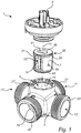
- Fig. 1 illustrates a fluid control valve 1.
- the fluid control valve 1 is shown in an exploded view to facilitate the illustration of different features thereof.
- the fluid control valve 1 is intended for controlling flow of liquid in a pipe system and may be used e.g. for controlling liquid flow in a heating and/or cooling system in a building.
- the fluid control valve 1 may be connected as a mixing valve to mix streams of fluid, as a diverting valve or as a combined mixing and diverting valve.
- the fluid control valve 1 comprises a housing 3, defining a circular cylindrical valve chamber 5, a rotor 7 and an operating spindle 9 for operating the rotor 7.
- the operating spindle 9 is configured to be connected to a knob for manual valve control, or to an electronic controller for automatic valve control.
- the rotor 7 is shaped to unrotatably engage with a driver of the operating spindle 9.
- the rotor 7 is rotatable around a rotor center axis 10.
- the valve chamber 5 comprises four ports 11, 13, 15, 17 distributed around a circumferential chamber wall 19 and four connecting conduits 21, 23, 25, 27.
- Each of the four connecting conduits 21, 23, 25, 27, which are arranged on equal height around the circumferential chamber wall 19, is fluidly connected to the valve chamber 5 by a respective one of the four ports 11, 13, 15, 17.
- the first port 11 and the associated connecting conduit 21 are situated opposite to the third port 15 and the associated connecting conduit 25 and the second port 13 and the associated connecting conduit 23 are situated opposite to the fourth port 17 and the associated connecting conduit 27.
- the size of all four ports 11, 13, 15, 17 is such that intact parts of the circumferential chamber wall 19 remain around all four ports 11, 13, 15, 17.
- each of the ports 13, 15 and 17 forms an inlet port and the first port 11 forms an outlet port.
- the rotor 7 comprises a first blocking portion 29, a second blocking portion 31 and a flow passage 33.
- Each of the first and second blocking portions 29, 31 is capable of blocking possible fluid paths through the valve 1.
- the flow passage 33 which has an inlet and an outlet, is disposed between the blocking portions 29, 31 and enables fluid communication through the valve rotor 7.
- the flow passage inlet is formed by a first side opening 35, illustrated in Fig. 2b , of the valve rotor 7 and the flow passage outlet is formed by a second side opening 37, illustrated in Fig. 2a , of the valve rotor 7.
- the rotor 7 is rotatably seated inside the chamber 5 of the valve housing 3 and is rotatable around the rotor center axis 10 between different operating positions to control fluid flow through the valve 1.
- the overall shape of the rotor 7 is circular cylindrical.
- a top plateau 39 of the rotor 7 has a groove 41, shaped to unrotatably engage with a driver of the operating spindle 9 in order to enable manual or automatic control of the valve 1 by rotating the rotor 7 such that the four port arrangement openings 11, 13, 15, 17 are opened totally or partly or closed.
- the valve rotor 7 comprises a sealing member in the form of an elastic sealing member 43.
- Fig. 2a and Fig. 2b show different sides of the valve rotor 7 without the sealing member 43 to facilitate the illustration of certain features of the valve rotor 7.
- a sealing member groove arrangement 45 is formed in the valve rotor 7.
- the sealing member groove arrangement 45 is adapted to receive the sealing member 43.
- the sealing member groove arrangement 45 comprises several groove portions 45a, 45b, 45c, each of which is adapted to receive a part of the sealing member 43.
- the sealing member groove arrangement 45 comprises a first circumferential groove portion 45a, a second circumferential groove portion 45b and four axial grove portions 45c.
- the rotor 7 is arranged to sealingly contact the circumferential chamber wall 19 and to close at least one of the valve ports 11, 13, 15, 17.
- the second port 13, i.e. one of the inlet ports of the valve 1 is closed by the first blocking portion 29 of the valve rotor 7 and the fourth port 17, i.e. another one of the inlet ports of the valve 1, is closed by the second blocking portion 31 of the valve rotor 7, while the flow passage 33 of the valve rotor 7 allows fluid communication between the third port 15, i.e. one of the inlet ports of the valve 1, and the first port 11, i.e. the outlet port of the valve 1.
- valve rotor 7 comprises a flow passage 33 for fluid communication therethrough, which flow passage 33 has an inlet 35, illustrated in Fig. 2b , and an outlet 37, illustrated in Fig. 2a .
- the size of the flow passage inlet 35 is larger than the flow passage outlet 37.
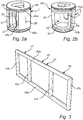
- Fig. 3 shows the sealing member 43.
- the sealing member 43 which is formed as one single piece, is configured to be received in the sealing member groove arrangement 45 formed in the valve rotor 7 and move together therewith.
- the sealing member 43 comprises two parallel side members 43a, 43b, each of which is configured to be received in a respective groove portion 45a, 45b of the sealing member groove 45, and intermediate members 43c extending between the parallel side members 43a, 43b and configured to be received in a respective axial groove 45c of the sealing member groove 45.
- the intermediate members 43c thus connect the parallel side members 43a, 43b with each other.
- the sealing member 43 is thus ladder-shaped. The distance between the intermediate members 43c, i.e.
- the sealing member 43 and the sealing member groove 45 are thus complementary in shape.
- the ladder-shaped sealing member 43 thus forms a first portion 47, which is configured to surround the first blocking portion 29 of the valve rotor 7, a second portion 49, which is configured to surround the flow passage inlet 35, and a third portion 51, which is configured to surround the second blocking 31 portion of the valve rotor 7.
- first sealing member portion 47 surrounds the first blocking portion 29 of the valve rotor 7
- second sealing member portion 49 surrounds the flow passage inlet 35 of the valve rotor 7
- the third sealing member portion 51 surrounds the second blocking portion 31 of the valve rotor 7.
- each of the first, second and third sealing member portions 47, 49, 51 forms a sealing portion.
- each of the first and third sealing member portions 47, 49 forms an anchoring portion, i.e. a portion that secures that the sealing member 43 is held in position during use of the valve 1.
- the first, second and third sealing member portions 47, 49, 51 are integrally formed with each other.
- the sealing member 43 is preferably formed from an elastomeric material, such as, e.g., EPDM.
- Fig. 4a shows an intermediate assembling state in which an axial sealing member portion 43c of the sealing member 43 has been placed in an axial groove portion 45c of the sealing member groove arrangement 45.
- the sealing member 43 is then slightly stretched and "rolled" on the valve rotor 7, as illustrated by arrow A in Fig. 4b , to an installed position, illustrated in Fig. 4b .
- each of the anchoring portions 47, 49 is thus stretched to fasten the sealing member 43 to the valve rotor 7.
- the sealing member 43 In the installed position the sealing member 43 is received in the sealing member groove arrangement 45.
- the sealing member 43 is maintained in the sealing member groove arrangement 45 due to the inherent elasticity of the elastic sealing member 43.
- Fig. 5 illustrates, in an exploded view, a fluid control valve 101 according to a second embodiment of the present disclosure.
- the fluid control valve 101 is intended for controlling flow of liquid in a pipe system and may be used e.g. for controlling liquid flow in a heating and/or cooling system in a building.
- the fluid control valve 101 may be connected as a mixing valve to mix streams of fluid, as a diverting valve or as a combined mixing and diverting valve.
- the fluid control valve 101 comprises a housing 103, defining a circular cylindrical valve chamber 105, a rotor 107 and an operating spindle 109 for operating the rotor 107.
- the operating spindle 109 is configured to be connected to a knob for manual valve control, or to an electronic controller for automatic valve control.
- the rotor 107 is shaped to unrotatably engage with a driver of the operating spindle 109.
- the rotor 107 is rotatable around a rotor center axis 110.
- the valve chamber 105 comprises three valve ports 111, 113, 115 distributed around a circumferential chamber wall 119 and three connecting conduits 121, 123, 125.
- each of the ports 113 and 115 forms an inlet port and the first port 111 forms an outlet port.
- the rotor 107 comprises a blocking portion 129, which is capable of blocking possible fluid paths through the valve 101, and a flow passage 133 which enables fluid communication through the valve 101.
- the rotor 107 is rotatably seated inside the chamber 105 of the valve housing 103 and is rotatable around the rotor center axis 110 between different operating positions to control fluid flow through the valve 101.
- the overall shape of the rotor 107 is circular cylindrical.
- a top plateau 139 of the rotor 107 has a groove 141, shaped to unrotatably engage with a driver of the operating spindle 109 in order to enable manual or automatic control of the valve 101 by rotating the rotor 107 such that the three valve ports 111, 113, 115 are opened totally or partly or closed.
- the valve rotor 107 comprises a sealing member in the form of an elastic sealing member 143.
- a sealing member groove arrangement 145 is formed in the valve rotor 107, which groove arrangement 145 is adapted to receive the sealing member 143.
- the sealing member groove arrangement 145 comprises several groove portions 145a, 145b, each of which is adapted to receive a part of the sealing member 143.
- the sealing member groove arrangement 145 comprises a first circumferential groove portion 145a, a second circumferential groove portion 145b and two axial grove portions (not shown).
- the rotor 107 is arranged to sealingly contact the circumferential chamber wall 119 and to close one of the valve ports 111, 113, 115.
- the first port 111 i.e. the outlet port of the valve 101
- the blocking portion 129 of the valve rotor 107 Fluid flow through the valve 101 is thus blocked when the valve rotor 107 assumes the position illustrated in Fig. 5 .
- the sealing member 143 which is formed as one single piece, is configured to be received in the sealing member groove arrangement 145 formed in the valve rotor 107 and move together therewith.
- the sealing member 143 comprises two parallel side members 143a, 143b, each of which is configured to be received in a respective groove portion 145a, 145b of the sealing member groove 145, and intermediate members 143c extending between the parallel side members 143a, 143b and configured to be received in a respective axial groove (not shown) of the sealing member groove arrangement 145.
- the intermediate members 143c thus connect the parallel side members 143a, 143b with each other.
- the sealing member 143 is thus ladder-shaped. The distance between the intermediate members 43c, i.e.
- the sealing member 143 and the sealing member groove arrangement 145 are thus complementary in shape.
- the sealing member 143 comprises a first portion in the form of a sealing portion 147, which is configured to surround the blocking portion 129 of the valve rotor 7. Hence, when the sealing member 143 is received in the sealing member groove arrangement 145 the first sealing member portion 147 surrounds the blocking portion 129 of the valve rotor 107.
- the sealing member 143 further comprises a second portion, in the form of a first elastic anchoring portion 149, and a third portion, in the form of a second elastic anchoring portion 151, each of which anchoring portions 149, 151 is mainly configured to secure the sealing member 143 to the valve rotor 107.
- the anchoring portions are configured to hold the sealing member in place.
- each of the first and second anchoring portions 149, 151 comprises two anchors 149a, 149b and 151a, 151b, respectively.
- the first anchoring portion 149 comprises a first elongated member having a free end at which the first anchor 149a of the first anchoring portion 149 is arranged and a second elongated member having a free end at which the second anchor 149b of the first anchoring portion 149 is arranged.
- the second anchoring portion 151 comprises a first elongated member having a free end at which the first anchor 151a of the second anchoring portion 151 is arranged and a second elongated member having a free end at which the second anchor 151b of the second anchoring portion 151 is arranged.
- Each of the first and second anchoring portions 149, 151 thus comprises two elongated members, each of which at a free end thereof is provided with an anchor.
- the sealing member groove arrangement 145 of the valve rotor 107 comprises four recesses, in the form of circular recesses, each of which is configured to receive a respective one of the anchors 149a, 149b, 151a, 151b of the sealing member 143.
- the first anchoring portion 149 projects from one side 153 of the sealing portion 147 of the sealing member 143 and the second anchoring portion 151 projects from an opposite side 155 of the sealing portion 147 of the sealing member 143, which secures a robust installation of the sealing member 143.
- Each of the anchoring portions 149, 151 is integrally formed with the sealing portion 147.
- the elastic anchor portions 149, 151 of the sealing member 143 are thus slightly stretched, which secures a robust installation of the sealing member 143.
- each of the anchoring portions 147, 149 is thus stretched to fasten the sealing member 143 to the valve rotor 107.
- each of the anchors 149a, 149b, 151a, 151b is received in a respective recess of the sealing member groove arrangement 145 and engages therewith.
- the sealing member 143 is maintained in the sealing member groove arrangement 145 due to the inherent elasticity of the elastic sealing member 143.
- the sealing member 143 is preferably formed from an elastomeric material, such as, e.g., EPDM.
- the embodiments described above concerns fluid valves in the form of mixing valves.
- the invention is not limited to fluid valves of that kind, but can be applied to shut off and diverting valves as well.
- the embodiments described above concerns fluid valves having three or four valve ports.
- the invention is not limited to fluid valves of that kind, but can be applied to valves having two valve ports, such as two way shut off valves, or valves having more than four valve ports.
Landscapes
- Engineering & Computer Science (AREA)
- General Engineering & Computer Science (AREA)
- Mechanical Engineering (AREA)
- Multiple-Way Valves (AREA)
Priority Applications (4)
| Application Number | Priority Date | Filing Date | Title |
|---|---|---|---|
| SI201530902T SI3067597T1 (sl) | 2015-03-09 | 2015-03-09 | Uporaba ventila za krmiljenje fluida |
| PL15158175T PL3067597T3 (pl) | 2015-03-09 | 2015-03-09 | Zastosowanie zaworu regulacji płynu |
| EP15158175.8A EP3067597B1 (en) | 2015-03-09 | 2015-03-09 | Use of a fluid control valve |
| ES15158175T ES2748176T3 (es) | 2015-03-09 | 2015-03-09 | Uso de una válvula de control de fluido |
Applications Claiming Priority (1)
| Application Number | Priority Date | Filing Date | Title |
|---|---|---|---|
| EP15158175.8A EP3067597B1 (en) | 2015-03-09 | 2015-03-09 | Use of a fluid control valve |
Publications (2)
| Publication Number | Publication Date |
|---|---|
| EP3067597A1 EP3067597A1 (en) | 2016-09-14 |
| EP3067597B1 true EP3067597B1 (en) | 2019-08-07 |
Family
ID=52630259
Family Applications (1)
| Application Number | Title | Priority Date | Filing Date |
|---|---|---|---|
| EP15158175.8A Active EP3067597B1 (en) | 2015-03-09 | 2015-03-09 | Use of a fluid control valve |
Country Status (4)
| Country | Link |
|---|---|
| EP (1) | EP3067597B1 (pl) |
| ES (1) | ES2748176T3 (pl) |
| PL (1) | PL3067597T3 (pl) |
| SI (1) | SI3067597T1 (pl) |
Families Citing this family (4)
| Publication number | Priority date | Publication date | Assignee | Title |
|---|---|---|---|---|
| DE202017101386U1 (de) * | 2017-03-10 | 2017-05-10 | Watts Industries Deutschland Gmbh | Armatur |
| EP3964739B1 (en) | 2020-09-04 | 2023-03-29 | Le Joint Français Snc | Sealing gasket for valve using a dynamic element |
| CN113883304B (zh) * | 2021-03-03 | 2025-10-28 | 浙江盾安机械有限公司 | 一种四通阀 |
| DE102023201155B4 (de) | 2023-02-13 | 2025-10-30 | Volkswagen Aktiengesellschaft | Dichtung umfassend eine Mehrzahl von Dichtungselementen |
Citations (1)
| Publication number | Priority date | Publication date | Assignee | Title |
|---|---|---|---|---|
| WO2014138786A1 (en) * | 2013-03-12 | 2014-09-18 | Gsa Industries (Aust) Pty Ltd | Water temperature regulating valve |
Family Cites Families (4)
| Publication number | Priority date | Publication date | Assignee | Title |
|---|---|---|---|---|
| FR2204281A5 (pl) * | 1972-10-23 | 1974-05-17 | Mannviller Pierre | |
| US3938553A (en) | 1973-11-08 | 1976-02-17 | Robert Ortega | Valve construction |
| FR2719100B1 (fr) * | 1994-04-20 | 1996-07-12 | Safi | Vanne à palette. |
| DE19712680A1 (de) * | 1997-03-26 | 1998-10-01 | Mann & Hummel Filter | Schaltwalze, insbesondere zur Verwendung in einer Saugrohranlage für eine Mehrzylinder-Brennkraftmaschine |
-
2015
- 2015-03-09 ES ES15158175T patent/ES2748176T3/es active Active
- 2015-03-09 EP EP15158175.8A patent/EP3067597B1/en active Active
- 2015-03-09 PL PL15158175T patent/PL3067597T3/pl unknown
- 2015-03-09 SI SI201530902T patent/SI3067597T1/sl unknown
Patent Citations (1)
| Publication number | Priority date | Publication date | Assignee | Title |
|---|---|---|---|---|
| WO2014138786A1 (en) * | 2013-03-12 | 2014-09-18 | Gsa Industries (Aust) Pty Ltd | Water temperature regulating valve |
Also Published As
| Publication number | Publication date |
|---|---|
| SI3067597T1 (sl) | 2019-12-31 |
| EP3067597A1 (en) | 2016-09-14 |
| ES2748176T3 (es) | 2020-03-13 |
| PL3067597T3 (pl) | 2020-04-30 |
Similar Documents
| Publication | Publication Date | Title |
|---|---|---|
| EP3072727B1 (en) | Valve device for vehicle | |
| US9523434B2 (en) | Flow passage switching valve | |
| EP3067597B1 (en) | Use of a fluid control valve | |
| EP3550189B1 (en) | Flow control device | |
| CN107690543B (zh) | 具有旁通回路的多通阀 | |
| JP6656846B2 (ja) | 流路切換弁及びシール部材 | |
| US9182045B2 (en) | Concentric diverter cartridge | |
| EP3295064B1 (en) | Combined butterfly/ball valve | |
| KR102166939B1 (ko) | 멀티 포트 밸브 | |
| EP3739244B1 (en) | Eccentric butterfly valve | |
| KR101892604B1 (ko) | 밸브 조립체 | |
| KR20170128087A (ko) | 버터플라이 밸브 | |
| US20150136259A1 (en) | Valve for controlling a flow of fluid, including a rotary closure means | |
| US20140209828A1 (en) | Flow characterizing device and ball valve with such a flow characterizing device | |
| EP3153748B1 (en) | Flow channel switching valve | |
| KR102134220B1 (ko) | 멀티 포트 밸브 | |
| JP6399860B2 (ja) | 流路切換弁 | |
| KR101793580B1 (ko) | 전동식 2라인 삼방볼밸브 | |
| EP2565502B1 (en) | Tap for water supply pipes | |
| US20240229942A1 (en) | Throttle valve | |
| US20240318733A1 (en) | Multi-way valve | |
| CN216078379U (zh) | 一种截止阀组件 | |
| JP6709409B2 (ja) | バタフライバルブ | |
| JP6711967B2 (ja) | バタフライバルブ | |
| CN213871229U (zh) | 可接多条管道的阀门 |
Legal Events
| Date | Code | Title | Description |
|---|---|---|---|
| PUAI | Public reference made under article 153(3) epc to a published international application that has entered the european phase |
Free format text: ORIGINAL CODE: 0009012 |
|
| AK | Designated contracting states |
Kind code of ref document: A1 Designated state(s): AL AT BE BG CH CY CZ DE DK EE ES FI FR GB GR HR HU IE IS IT LI LT LU LV MC MK MT NL NO PL PT RO RS SE SI SK SM TR |
|
| AX | Request for extension of the european patent |
Extension state: BA ME |
|
| STAA | Information on the status of an ep patent application or granted ep patent |
Free format text: STATUS: REQUEST FOR EXAMINATION WAS MADE |
|
| 17P | Request for examination filed |
Effective date: 20170314 |
|
| RBV | Designated contracting states (corrected) |
Designated state(s): AL AT BE BG CH CY CZ DE DK EE ES FI FR GB GR HR HU IE IS IT LI LT LU LV MC MK MT NL NO PL PT RO RS SE SI SK SM TR |
|
| RAP1 | Party data changed (applicant data changed or rights of an application transferred) |
Owner name: ESBE AB |
|
| STAA | Information on the status of an ep patent application or granted ep patent |
Free format text: STATUS: EXAMINATION IS IN PROGRESS |
|
| 17Q | First examination report despatched |
Effective date: 20180309 |
|
| GRAP | Despatch of communication of intention to grant a patent |
Free format text: ORIGINAL CODE: EPIDOSNIGR1 |
|
| STAA | Information on the status of an ep patent application or granted ep patent |
Free format text: STATUS: GRANT OF PATENT IS INTENDED |
|
| INTG | Intention to grant announced |
Effective date: 20190301 |
|
| GRAS | Grant fee paid |
Free format text: ORIGINAL CODE: EPIDOSNIGR3 |
|
| GRAA | (expected) grant |
Free format text: ORIGINAL CODE: 0009210 |
|
| STAA | Information on the status of an ep patent application or granted ep patent |
Free format text: STATUS: THE PATENT HAS BEEN GRANTED |
|
| AK | Designated contracting states |
Kind code of ref document: B1 Designated state(s): AL AT BE BG CH CY CZ DE DK EE ES FI FR GB GR HR HU IE IS IT LI LT LU LV MC MK MT NL NO PL PT RO RS SE SI SK SM TR |
|
| REG | Reference to a national code |
Ref country code: GB Ref legal event code: FG4D |
|
| REG | Reference to a national code |
Ref country code: CH Ref legal event code: EP Ref country code: AT Ref legal event code: REF Ref document number: 1164400 Country of ref document: AT Kind code of ref document: T Effective date: 20190815 |
|
| REG | Reference to a national code |
Ref country code: DE Ref legal event code: R096 Ref document number: 602015035084 Country of ref document: DE |
|
| REG | Reference to a national code |
Ref country code: IE Ref legal event code: FG4D |
|
| REG | Reference to a national code |
Ref country code: CH Ref legal event code: NV Representative=s name: WEINMANN ZIMMERLI, CH |
|
| REG | Reference to a national code |
Ref country code: SE Ref legal event code: TRGR |
|
| REG | Reference to a national code |
Ref country code: NL Ref legal event code: MP Effective date: 20190807 |
|
| REG | Reference to a national code |
Ref country code: NO Ref legal event code: T2 Effective date: 20190807 |
|
| REG | Reference to a national code |
Ref country code: LT Ref legal event code: MG4D |
|
| PG25 | Lapsed in a contracting state [announced via postgrant information from national office to epo] |
Ref country code: LT Free format text: LAPSE BECAUSE OF FAILURE TO SUBMIT A TRANSLATION OF THE DESCRIPTION OR TO PAY THE FEE WITHIN THE PRESCRIBED TIME-LIMIT Effective date: 20190807 Ref country code: BG Free format text: LAPSE BECAUSE OF FAILURE TO SUBMIT A TRANSLATION OF THE DESCRIPTION OR TO PAY THE FEE WITHIN THE PRESCRIBED TIME-LIMIT Effective date: 20191107 Ref country code: NL Free format text: LAPSE BECAUSE OF FAILURE TO SUBMIT A TRANSLATION OF THE DESCRIPTION OR TO PAY THE FEE WITHIN THE PRESCRIBED TIME-LIMIT Effective date: 20190807 Ref country code: HR Free format text: LAPSE BECAUSE OF FAILURE TO SUBMIT A TRANSLATION OF THE DESCRIPTION OR TO PAY THE FEE WITHIN THE PRESCRIBED TIME-LIMIT Effective date: 20190807 Ref country code: PT Free format text: LAPSE BECAUSE OF FAILURE TO SUBMIT A TRANSLATION OF THE DESCRIPTION OR TO PAY THE FEE WITHIN THE PRESCRIBED TIME-LIMIT Effective date: 20191209 |
|
| PG25 | Lapsed in a contracting state [announced via postgrant information from national office to epo] |
Ref country code: IS Free format text: LAPSE BECAUSE OF FAILURE TO SUBMIT A TRANSLATION OF THE DESCRIPTION OR TO PAY THE FEE WITHIN THE PRESCRIBED TIME-LIMIT Effective date: 20191207 Ref country code: LV Free format text: LAPSE BECAUSE OF FAILURE TO SUBMIT A TRANSLATION OF THE DESCRIPTION OR TO PAY THE FEE WITHIN THE PRESCRIBED TIME-LIMIT Effective date: 20190807 Ref country code: GR Free format text: LAPSE BECAUSE OF FAILURE TO SUBMIT A TRANSLATION OF THE DESCRIPTION OR TO PAY THE FEE WITHIN THE PRESCRIBED TIME-LIMIT Effective date: 20191108 Ref country code: RS Free format text: LAPSE BECAUSE OF FAILURE TO SUBMIT A TRANSLATION OF THE DESCRIPTION OR TO PAY THE FEE WITHIN THE PRESCRIBED TIME-LIMIT Effective date: 20190807 Ref country code: AL Free format text: LAPSE BECAUSE OF FAILURE TO SUBMIT A TRANSLATION OF THE DESCRIPTION OR TO PAY THE FEE WITHIN THE PRESCRIBED TIME-LIMIT Effective date: 20190807 |
|
| REG | Reference to a national code |
Ref country code: ES Ref legal event code: FG2A Ref document number: 2748176 Country of ref document: ES Kind code of ref document: T3 Effective date: 20200313 |
|
| PG25 | Lapsed in a contracting state [announced via postgrant information from national office to epo] |
Ref country code: RO Free format text: LAPSE BECAUSE OF FAILURE TO SUBMIT A TRANSLATION OF THE DESCRIPTION OR TO PAY THE FEE WITHIN THE PRESCRIBED TIME-LIMIT Effective date: 20190807 Ref country code: EE Free format text: LAPSE BECAUSE OF FAILURE TO SUBMIT A TRANSLATION OF THE DESCRIPTION OR TO PAY THE FEE WITHIN THE PRESCRIBED TIME-LIMIT Effective date: 20190807 Ref country code: DK Free format text: LAPSE BECAUSE OF FAILURE TO SUBMIT A TRANSLATION OF THE DESCRIPTION OR TO PAY THE FEE WITHIN THE PRESCRIBED TIME-LIMIT Effective date: 20190807 |
|
| PG25 | Lapsed in a contracting state [announced via postgrant information from national office to epo] |
Ref country code: SK Free format text: LAPSE BECAUSE OF FAILURE TO SUBMIT A TRANSLATION OF THE DESCRIPTION OR TO PAY THE FEE WITHIN THE PRESCRIBED TIME-LIMIT Effective date: 20190807 Ref country code: SM Free format text: LAPSE BECAUSE OF FAILURE TO SUBMIT A TRANSLATION OF THE DESCRIPTION OR TO PAY THE FEE WITHIN THE PRESCRIBED TIME-LIMIT Effective date: 20190807 Ref country code: IS Free format text: LAPSE BECAUSE OF FAILURE TO SUBMIT A TRANSLATION OF THE DESCRIPTION OR TO PAY THE FEE WITHIN THE PRESCRIBED TIME-LIMIT Effective date: 20200224 |
|
| REG | Reference to a national code |
Ref country code: DE Ref legal event code: R097 Ref document number: 602015035084 Country of ref document: DE |
|
| PLBE | No opposition filed within time limit |
Free format text: ORIGINAL CODE: 0009261 |
|
| STAA | Information on the status of an ep patent application or granted ep patent |
Free format text: STATUS: NO OPPOSITION FILED WITHIN TIME LIMIT |
|
| PG2D | Information on lapse in contracting state deleted |
Ref country code: IS |
|
| 26N | No opposition filed |
Effective date: 20200603 |
|
| PG25 | Lapsed in a contracting state [announced via postgrant information from national office to epo] |
Ref country code: MC Free format text: LAPSE BECAUSE OF FAILURE TO SUBMIT A TRANSLATION OF THE DESCRIPTION OR TO PAY THE FEE WITHIN THE PRESCRIBED TIME-LIMIT Effective date: 20190807 |
|
| REG | Reference to a national code |
Ref country code: BE Ref legal event code: MM Effective date: 20200331 |
|
| PG25 | Lapsed in a contracting state [announced via postgrant information from national office to epo] |
Ref country code: LU Free format text: LAPSE BECAUSE OF NON-PAYMENT OF DUE FEES Effective date: 20200309 |
|
| PG25 | Lapsed in a contracting state [announced via postgrant information from national office to epo] |
Ref country code: IE Free format text: LAPSE BECAUSE OF NON-PAYMENT OF DUE FEES Effective date: 20200309 |
|
| PG25 | Lapsed in a contracting state [announced via postgrant information from national office to epo] |
Ref country code: BE Free format text: LAPSE BECAUSE OF NON-PAYMENT OF DUE FEES Effective date: 20200331 |
|
| PG25 | Lapsed in a contracting state [announced via postgrant information from national office to epo] |
Ref country code: MT Free format text: LAPSE BECAUSE OF FAILURE TO SUBMIT A TRANSLATION OF THE DESCRIPTION OR TO PAY THE FEE WITHIN THE PRESCRIBED TIME-LIMIT Effective date: 20190807 Ref country code: CY Free format text: LAPSE BECAUSE OF FAILURE TO SUBMIT A TRANSLATION OF THE DESCRIPTION OR TO PAY THE FEE WITHIN THE PRESCRIBED TIME-LIMIT Effective date: 20190807 |
|
| PG25 | Lapsed in a contracting state [announced via postgrant information from national office to epo] |
Ref country code: MK Free format text: LAPSE BECAUSE OF FAILURE TO SUBMIT A TRANSLATION OF THE DESCRIPTION OR TO PAY THE FEE WITHIN THE PRESCRIBED TIME-LIMIT Effective date: 20190807 |
|
| PGFP | Annual fee paid to national office [announced via postgrant information from national office to epo] |
Ref country code: DE Payment date: 20250219 Year of fee payment: 11 |
|
| PGFP | Annual fee paid to national office [announced via postgrant information from national office to epo] |
Ref country code: FI Payment date: 20250217 Year of fee payment: 11 |
|
| PGFP | Annual fee paid to national office [announced via postgrant information from national office to epo] |
Ref country code: SE Payment date: 20250217 Year of fee payment: 11 |
|
| PGFP | Annual fee paid to national office [announced via postgrant information from national office to epo] |
Ref country code: NO Payment date: 20250227 Year of fee payment: 11 |
|
| PGFP | Annual fee paid to national office [announced via postgrant information from national office to epo] |
Ref country code: AT Payment date: 20250219 Year of fee payment: 11 Ref country code: SI Payment date: 20250227 Year of fee payment: 11 |
|
| PGFP | Annual fee paid to national office [announced via postgrant information from national office to epo] |
Ref country code: FR Payment date: 20250217 Year of fee payment: 11 Ref country code: PL Payment date: 20250228 Year of fee payment: 11 Ref country code: CZ Payment date: 20250303 Year of fee payment: 11 |
|
| PGFP | Annual fee paid to national office [announced via postgrant information from national office to epo] |
Ref country code: IT Payment date: 20250218 Year of fee payment: 11 Ref country code: GB Payment date: 20250218 Year of fee payment: 11 |
|
| PGFP | Annual fee paid to national office [announced via postgrant information from national office to epo] |
Ref country code: TR Payment date: 20250303 Year of fee payment: 11 |
|
| PGFP | Annual fee paid to national office [announced via postgrant information from national office to epo] |
Ref country code: ES Payment date: 20250402 Year of fee payment: 11 |
|
| PGFP | Annual fee paid to national office [announced via postgrant information from national office to epo] |
Ref country code: CH Payment date: 20250401 Year of fee payment: 11 |