EP3067589B1 - Automatic transmission control device - Google Patents
Automatic transmission control device Download PDFInfo
- Publication number
- EP3067589B1 EP3067589B1 EP14860834.2A EP14860834A EP3067589B1 EP 3067589 B1 EP3067589 B1 EP 3067589B1 EP 14860834 A EP14860834 A EP 14860834A EP 3067589 B1 EP3067589 B1 EP 3067589B1
- Authority
- EP
- European Patent Office
- Prior art keywords
- engagement
- rotation speed
- clutch
- vehicle
- automatic transmission
- Prior art date
- Legal status (The legal status is an assumption and is not a legal conclusion. Google has not performed a legal analysis and makes no representation as to the accuracy of the status listed.)
- Active
Links
- 230000005540 biological transmission Effects 0.000 title claims description 109
- 230000008878 coupling Effects 0.000 claims description 67
- 238000010168 coupling process Methods 0.000 claims description 67
- 238000005859 coupling reaction Methods 0.000 claims description 67
- 230000001133 acceleration Effects 0.000 claims description 20
- 230000035939 shock Effects 0.000 description 16
- 230000007246 mechanism Effects 0.000 description 13
- 230000000694 effects Effects 0.000 description 10
- 238000000034 method Methods 0.000 description 8
- 241000381592 Senegalia polyacantha Species 0.000 description 7
- 230000008569 process Effects 0.000 description 6
- 230000001360 synchronised effect Effects 0.000 description 6
- 238000010586 diagram Methods 0.000 description 4
- 230000002035 prolonged effect Effects 0.000 description 4
- 230000004044 response Effects 0.000 description 4
- 230000008859 change Effects 0.000 description 2
- 238000006073 displacement reaction Methods 0.000 description 2
- 230000009467 reduction Effects 0.000 description 2
- 238000004891 communication Methods 0.000 description 1
- 230000001186 cumulative effect Effects 0.000 description 1
- 238000005034 decoration Methods 0.000 description 1
- 230000001419 dependent effect Effects 0.000 description 1
- 230000009347 mechanical transmission Effects 0.000 description 1
- 230000007935 neutral effect Effects 0.000 description 1
- 238000002360 preparation method Methods 0.000 description 1
- 230000008929 regeneration Effects 0.000 description 1
- 238000011069 regeneration method Methods 0.000 description 1
- 230000007704 transition Effects 0.000 description 1
Images


Classifications
-
- F—MECHANICAL ENGINEERING; LIGHTING; HEATING; WEAPONS; BLASTING
- F16—ENGINEERING ELEMENTS AND UNITS; GENERAL MEASURES FOR PRODUCING AND MAINTAINING EFFECTIVE FUNCTIONING OF MACHINES OR INSTALLATIONS; THERMAL INSULATION IN GENERAL
- F16H—GEARING
- F16H61/00—Control functions within control units of change-speed- or reversing-gearings for conveying rotary motion ; Control of exclusively fluid gearing, friction gearing, gearings with endless flexible members or other particular types of gearing
- F16H61/04—Smoothing ratio shift
- F16H61/0403—Synchronisation before shifting
-
- F—MECHANICAL ENGINEERING; LIGHTING; HEATING; WEAPONS; BLASTING
- F16—ENGINEERING ELEMENTS AND UNITS; GENERAL MEASURES FOR PRODUCING AND MAINTAINING EFFECTIVE FUNCTIONING OF MACHINES OR INSTALLATIONS; THERMAL INSULATION IN GENERAL
- F16H—GEARING
- F16H3/00—Toothed gearings for conveying rotary motion with variable gear ratio or for reversing rotary motion
- F16H3/02—Toothed gearings for conveying rotary motion with variable gear ratio or for reversing rotary motion without gears having orbital motion
- F16H3/08—Toothed gearings for conveying rotary motion with variable gear ratio or for reversing rotary motion without gears having orbital motion exclusively or essentially with continuously meshing gears, that can be disengaged from their shafts
- F16H3/087—Toothed gearings for conveying rotary motion with variable gear ratio or for reversing rotary motion without gears having orbital motion exclusively or essentially with continuously meshing gears, that can be disengaged from their shafts characterised by the disposition of the gears
- F16H3/089—Toothed gearings for conveying rotary motion with variable gear ratio or for reversing rotary motion without gears having orbital motion exclusively or essentially with continuously meshing gears, that can be disengaged from their shafts characterised by the disposition of the gears all of the meshing gears being supported by a pair of parallel shafts, one being the input shaft and the other the output shaft, there being no countershaft involved
-
- F—MECHANICAL ENGINEERING; LIGHTING; HEATING; WEAPONS; BLASTING
- F16—ENGINEERING ELEMENTS AND UNITS; GENERAL MEASURES FOR PRODUCING AND MAINTAINING EFFECTIVE FUNCTIONING OF MACHINES OR INSTALLATIONS; THERMAL INSULATION IN GENERAL
- F16H—GEARING
- F16H61/00—Control functions within control units of change-speed- or reversing-gearings for conveying rotary motion ; Control of exclusively fluid gearing, friction gearing, gearings with endless flexible members or other particular types of gearing
- F16H61/04—Smoothing ratio shift
-
- F—MECHANICAL ENGINEERING; LIGHTING; HEATING; WEAPONS; BLASTING
- F16—ENGINEERING ELEMENTS AND UNITS; GENERAL MEASURES FOR PRODUCING AND MAINTAINING EFFECTIVE FUNCTIONING OF MACHINES OR INSTALLATIONS; THERMAL INSULATION IN GENERAL
- F16H—GEARING
- F16H63/00—Control outputs from the control unit to change-speed- or reversing-gearings for conveying rotary motion or to other devices than the final output mechanism
- F16H63/02—Final output mechanisms therefor; Actuating means for the final output mechanisms
- F16H63/30—Constructional features of the final output mechanisms
- F16H63/34—Locking or disabling mechanisms
- F16H63/3416—Parking lock mechanisms or brakes in the transmission
- F16H63/3458—Parking lock mechanisms or brakes in the transmission with electric actuating means, e.g. shift by wire
- F16H63/3466—Parking lock mechanisms or brakes in the transmission with electric actuating means, e.g. shift by wire using electric motors
-
- F—MECHANICAL ENGINEERING; LIGHTING; HEATING; WEAPONS; BLASTING
- F16—ENGINEERING ELEMENTS AND UNITS; GENERAL MEASURES FOR PRODUCING AND MAINTAINING EFFECTIVE FUNCTIONING OF MACHINES OR INSTALLATIONS; THERMAL INSULATION IN GENERAL
- F16H—GEARING
- F16H63/00—Control outputs from the control unit to change-speed- or reversing-gearings for conveying rotary motion or to other devices than the final output mechanism
- F16H63/40—Control outputs from the control unit to change-speed- or reversing-gearings for conveying rotary motion or to other devices than the final output mechanism comprising signals other than signals for actuating the final output mechanisms
- F16H63/50—Signals to an engine or motor
- F16H63/502—Signals to an engine or motor for smoothing gear shifts
-
- B—PERFORMING OPERATIONS; TRANSPORTING
- B60—VEHICLES IN GENERAL
- B60Y—INDEXING SCHEME RELATING TO ASPECTS CROSS-CUTTING VEHICLE TECHNOLOGY
- B60Y2200/00—Type of vehicle
- B60Y2200/90—Vehicles comprising electric prime movers
- B60Y2200/91—Electric vehicles
-
- F—MECHANICAL ENGINEERING; LIGHTING; HEATING; WEAPONS; BLASTING
- F16—ENGINEERING ELEMENTS AND UNITS; GENERAL MEASURES FOR PRODUCING AND MAINTAINING EFFECTIVE FUNCTIONING OF MACHINES OR INSTALLATIONS; THERMAL INSULATION IN GENERAL
- F16H—GEARING
- F16H61/00—Control functions within control units of change-speed- or reversing-gearings for conveying rotary motion ; Control of exclusively fluid gearing, friction gearing, gearings with endless flexible members or other particular types of gearing
- F16H61/04—Smoothing ratio shift
- F16H61/0403—Synchronisation before shifting
- F16H2061/0418—Synchronisation before shifting by using different synchronisation devices simultaneously, e.g. for faster synchronisation
-
- F—MECHANICAL ENGINEERING; LIGHTING; HEATING; WEAPONS; BLASTING
- F16—ENGINEERING ELEMENTS AND UNITS; GENERAL MEASURES FOR PRODUCING AND MAINTAINING EFFECTIVE FUNCTIONING OF MACHINES OR INSTALLATIONS; THERMAL INSULATION IN GENERAL
- F16H—GEARING
- F16H61/00—Control functions within control units of change-speed- or reversing-gearings for conveying rotary motion ; Control of exclusively fluid gearing, friction gearing, gearings with endless flexible members or other particular types of gearing
- F16H61/04—Smoothing ratio shift
- F16H61/0403—Synchronisation before shifting
- F16H2061/0422—Synchronisation before shifting by an electric machine, e.g. by accelerating or braking the input shaft
-
- F—MECHANICAL ENGINEERING; LIGHTING; HEATING; WEAPONS; BLASTING
- F16—ENGINEERING ELEMENTS AND UNITS; GENERAL MEASURES FOR PRODUCING AND MAINTAINING EFFECTIVE FUNCTIONING OF MACHINES OR INSTALLATIONS; THERMAL INSULATION IN GENERAL
- F16H—GEARING
- F16H61/00—Control functions within control units of change-speed- or reversing-gearings for conveying rotary motion ; Control of exclusively fluid gearing, friction gearing, gearings with endless flexible members or other particular types of gearing
- F16H61/04—Smoothing ratio shift
- F16H2061/047—Smoothing ratio shift by preventing or solving a tooth butt situation upon engagement failure due to misalignment of teeth
-
- F—MECHANICAL ENGINEERING; LIGHTING; HEATING; WEAPONS; BLASTING
- F16—ENGINEERING ELEMENTS AND UNITS; GENERAL MEASURES FOR PRODUCING AND MAINTAINING EFFECTIVE FUNCTIONING OF MACHINES OR INSTALLATIONS; THERMAL INSULATION IN GENERAL
- F16H—GEARING
- F16H2306/00—Shifting
- F16H2306/40—Shifting activities
- F16H2306/48—Synchronising of new gear
-
- Y—GENERAL TAGGING OF NEW TECHNOLOGICAL DEVELOPMENTS; GENERAL TAGGING OF CROSS-SECTIONAL TECHNOLOGIES SPANNING OVER SEVERAL SECTIONS OF THE IPC; TECHNICAL SUBJECTS COVERED BY FORMER USPC CROSS-REFERENCE ART COLLECTIONS [XRACs] AND DIGESTS
- Y02—TECHNOLOGIES OR APPLICATIONS FOR MITIGATION OR ADAPTATION AGAINST CLIMATE CHANGE
- Y02T—CLIMATE CHANGE MITIGATION TECHNOLOGIES RELATED TO TRANSPORTATION
- Y02T10/00—Road transport of goods or passengers
- Y02T10/60—Other road transportation technologies with climate change mitigation effect
- Y02T10/72—Electric energy management in electromobility
Definitions
- the present invention relates to an automatic transmission control device equipped with an automatic transmission having an engagement clutch disposed in a vehicle drive system and performing a meshing engagement as an engagement element.
- Patent Document 1 JP 2001-90826 A
- Prior art document EP 0 641 959 A2 suggests an automated mechanical transmission control system and method which are configured to course for both up shifts and downshifts the jaw clutch engagement when an input shaft is rotating at a speed equal to or slightly larger than an exact synchronous speed.
- Document WO 2010/119 504 A1 describes a drive controller for a vehicle having a control means allowing first and second engagement elements to engage under such a state that a differential rotation in a predetermined direction is imparted previously between said first and second engagement elements.
- Prior art document WO 2013/076218 A1 discloses a method and an apparatus for controlling the engagement of an input gear with an output gear which are configured in order to avoid the necessity for a mechanical synchromesh in order to smooth a transition from a low range to a high range and vice versa.
- the present invention has been made in consideration of the above problems, and, aims to provide an automatic control device in which the meshing failure of the engagement clutch may be prevented from occurring and the time until engagement completion may be prevented from being prolonged.
- an automatic transmission having an engagement clutch disposed in a vehicle drive system and operative in meshing engagement as a coupling element and a shift controller that executes a shift control of the automatic transmission are respectively provided.
- the engagement clutch is provided with a first engagement member connected to a transmission input shaft and a second engagement member connected to a transmission output shaft and being capable of meshing with the first engagement member.
- the shift controller is configured to set a target differential rotation speed when engaging the engagement clutch for shifting such that when the first engagement member and the second engagement member mesh each other a predetermined differential rotation is imparted between an input rotation speed representative of the rotation speed of the first engagement member and an output rotation speed representative of the rotation speed of the second engagement member.
- the magnitude of the target differential rotation speed is set according to the magnitude of the acceleration of the vehicle such that, as the magnitude of the acceleration of the vehicle increases, the target differential rotation speed is set larger.
- the shift controller when engaging the engagement clutch for shifting, is configured, when the first engagement member and the second engaging member mesh with each other, such that a target differential rotation speed is set to provide a predetermined differential rotation of the engagement clutch between the input rotation speed and the output rotation speed.
- the trouble may be avoidable to resume meshing operation after shifting the relative position between the first and the second engagement members. As a result, it is possible to prevent the time until engagement completion of the engagement clutch from being prolonged.
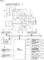
- FIG. 1 shows a drive system configuration and a control system configuration of an electric vehicle to which the shift control device in the first embodiment is applied. Below, with reference to FIG. 1 , the overall system configuration is described.
- a driving motor generator 2 As the drive system configuration of the electric vehicle (vehicle), as shown in FIG. 1 , a driving motor generator 2, an automatic transmission 3, and a drive wheel 14 are provided.
- the driving motor generator 2 is of a permanent magnet synchronous motor of three-phase alternating current and serves as a driving source for travel of the electric vehicle.
- the driving motor generator 2 when a positive torque (driving torque) command is output to the inverter (not shown) from a motor controller 28, generates a driving torque using a discharge power from a high voltage battery (not shown) so as to carry out a driving operation to drive the drive wheels 14 (power running).
- a negative torque (generation torque) command is output to the inverter from the motor controller 28, a power generating operation for converting rotational energy from the drive wheels 14 into electrical energy is performed, and the power thus generated is used as charging electric power in the high voltage battery (regeneration).
- a motor shaft of the driving motor generator 2 is connected to a transmission input shaft 6 of the automatic transmission 3.
- the automatic transmission 3 is a constant mesh-type stepped transmission which transmits power in one of two gear pairs of different transmission or speed ratios, in which two stage shifting are performed in which a high gear stage (high speed stage) with a low speed reduction ratio and a low gear stage with high speed reduction ratio.
- the automatic transmission 3 is used for gear shifting when outputting a motor power by passing from the driving motor generator 2 through a transmission input shaft 6 and a transmission output shaft 7 and is configured by a low side transmission mechanism 8 for realizing a low shift stage and a high side transmission mechanism 9 for realizing a high shift stage.
- the transmission input shaft 6 and the transmission output shaft 7 are disposed parallel to each other.
- the low side shift mechanism 8 is used for selecting a low-side transmission path at the time of outputting the motor power and is disposed on the transmission output shaft 7.
- the low side shift mechanism 8 is made up of an engagement clutch 83 (meshing element) which performs a meshing engagement/release of a gear 8a with respect to the transmission output shaft 7 in order for the low speed stage gear pair 80 (gear 8a, gear 8b) to drivingly connect between the transmission input shaft 6 and the transmission output shaft 7.
- the low speed stage gear pair 80 is composed of the gear 8a rotatably supported on the transmission output shaft 7 and the gear 8b which is meshed with the gear 8a and rotates jointly with the transmission input shaft 6.
- the high-side transmission mechanism 9 is intended, when outputting the motor power, for selecting a high-side transmission path and is arranged on the transmission input shaft 6.
- This high-speed side shift mechanism 9 is made up of a friction clutch 9c (engagement element) which performs a frictional engagement/release of a gear 9a with respect to the transmission input shaft 6 in order for the high speed stage gear pair 90 (gear 9a, gear 9b) to drivingly connect between the transmission input shaft 6 and the transmission output shaft 7.
- the high speed stage gear pair is composed of the gear 9a rotatably supported on the transmission input shaft 6 and the gear 9b which is meshed with the gear 9a and rotates jointly with the transmission output shaft 7.
- the motor power of the driving motor generator 2, which has reached the transmission output shaft 7 is configured to be further transmitted via the final drive gear set 11, 12, the differential gear unit 13, and the left and right drive shaft 16 to the drive wheels 14 (only one of the drive wheels is shown in FIG. 1 ).
- a parking gear 17 is fixed to the transmission output shaft 7 in the side opposite to the gear 11, and a parking pole 1 8 is arranged provided on a transmission case (not shown) so as to be able to be meshed with the parking gear 17.
- the transmission output shaft 7 is fixed to the transmission case so as to be unrotatable.
- a shift controller 21, a vehicle speed sensor 22, an accelerator opening sensor 23, a brake stroke sensor 24, a longitudinal acceleration sensor 25, a slider position sensor 26, a sleeve position sensor 27, a motor rotation speed sensor 33, a transmission output rotation speed sensor 34, and the like are provided.
- a motor controller 28, a brake controller 29, an integrated controller 30, a CAN communication line 31, and a range position switch 32 are provided.
- the shift controller 21 is composed of a microcomputer provided with a CPU (Central Processing Unit), a ROM (Read Only Memory), a RAM (Random Access Memory), a backup memory, and an I/O interface.
- the shift controller 21 outputs a shift command or request based on a shift map (not shown), and is further configured, when upshifting to a high gear stage in a state of low gear stage with the engaging clutch 8c in engaged state and the friction clutch 9c released, to perform a switching control to release the engaging clutch 8c and to frictionally connect the friction clutch 9c.
- the shift controller 21 performs a switching control to carry out meshing engagement of the engagement clutch 8c and release of the friction clutch 93. Further, at the time of downshifting, a shift control processing is executed as described below and the meshing engagement of the engagement clutch 8c will be controlled.
- the range position switch 32 is intended to be a switch which detects a range position of the automatic transmission 3, which has been selected in response to a driver's selecting operation with respect to a select lever (not shown).
- the positions detectable are P range (i.e. parking, non-driving, or parking range9, N range (i.e. neutral range), D range (i.e. drive range, forward driving range), R range (i.e. reverse range, reverse driving range), and the like.
- the motor rotation speed sensor 33 is provided for detecting an output rotation speed of the driving motor generator 2. In other words, the rotation speed of the transmission input shaft 6 is detected. That is, the rotation speed of the driving motor generator 2 (motor speed) corresponds to an input rotation speed (hereinafter, referred to as "clutch input rotation speed") to the engagement elements (engagement clutch 8c, friction clutch 9c) provided in the automatic transmission. Thus, the clutch input rotation speed is detected by the motor rotation speed sensor 33.
- the transmission output rotation speed sensor 34 is provided for detecting an output rotation speed of the automatic transmission 3. In other words, the rotation speed of the transmission output shaft 7 is detected. That is, the rotation speed of the transmission output shaft 7 corresponds to an output rotation speed (hereinafter, referred to as "clutch output rotation speed") of the engagement elements (engagement clutch 8c, friction clutch 9c) provided in the automatic transmission.
- the transmission output rotation speed sensor 34 detects the clutch output rotation speed.
- FIG. 2 shows a detailed configuration of a shift control system of the first embodiment.
- FIG. 3 is an explanatory diagram of the engagement clutch of the first embodiment. Below, with reference to FIGS. 2 and 3 , a detailed configuration of the shift control system in the first embodiment is described.
- an engagement clutch 8c, a friction clutch 9c, a parking gear 17, a driving motor generator 2, a hydraulic brake 15, a shift controller 21 are provided.
- the engagement clutch 8c, the friction clutch 9c, the driving motor generator 2, and the hydraulic brake 15 are subject to control, and depending on conditions, control is executed based on a request from the shift controller 21.
- the engagement clutch 8c is constructed in a clutch of synchronous meshing type, and includes a clutch gear 8a(first engagement member) provided on the gear 8d and a clutch hub (second engagement member) 8e attached to the transmission output shaft 7, and a coupling sleeve 8f (see FIG. 1 ). Further, by driving in stroke the coupling sleeve 8f by the first electric actuator 41, meshing engagement/release between the clutch gear 8d and the clutch hub 8e is performed via the coupling sleeve 8f. Note that, since the gear 8a is meshed with the gear 8b jointly rotatable with the transmission input shaft 6, the clutch gear 8d provided on the gear 8a is coupled to the transmission input shaft 6. In other words, when the clutch gear 8d and the clutch hub 8e are engaged by meshing, the transmission input shaft 6 and the transmission output shaft 7 are coupled.
- the meshing engagement or release of the engagement clutch 8c is determined by the position of the coupling sleeve 8f.
- the shift controller 21 reads the value of the sleeve position sensor 27 and is provided with a first position servo controller 51 (for example, position servo system with PID control) which provides a current to the first electric actuator 41, so that the position of the coupling sleeve 8f is located in the meshing engagement position or the release position.
- a first position servo controller 51 for example, position servo system with PID control
- the coupling sleeve 8f is formed in a cylindrical shape with both ends open and provided at its inner periphery with a plurality of spline portions 8fa constantly fit with clutch teeth (not shown) of the clutch gear 8d (see FIG. 1 ). Further, while maintaining a fitting state between the clutch teeth of the clutch gear 8d and the spline portions 8fa, the coupling sleeve 8f is supported movably axially, i.e., in the left-right direction in FIG. 3A . The axial movement of the coupling sleeve 8f is made by driving the first electric actuator 41 (see FIG. 2 ).
- the clutch hub 8e is formed with a plurality of clutch teeth 8ea on the outer periphery thereof, which may be fit into the spline portions 8fa formed on the inner periphery of the coupling sleeve 8f. That is, the clutch teeth 8ea of the clutch hub 8e will be engageable with the clutch teeth of the clutch gear 8d (not shown) via the coupling sleeve 8f. Furthermore, in the clutch hub 8e, the outer periphery of a tapered cone portion 8eb is fitted with a synchronizer ring 8g movably in the axial direction.
- the synchronizer ring 8g is formed with a plurality of synchro-teeth 8ga which can mesh with a plurality of the spline portions 8fa of the coupling sleeve 8f and key grooves 8gc which constantly mesh with keys 8h provided on the coupling sleeve 8f.
- a gap is provided between the key 8h and the key groove 8gc.
- the synchronizer ring 8g is configured to be movable in the rotational direction relative to the coupling sleeve 8f by the amount of the gap between the key 8h and the key groove 8gc.
- a chamfer portion 8gb of the synchro-teeth 8ga of the synchronizer ring 8g and a chamfer portion 8fb of the spline portion 8fa of the coupling sleeve 8f, as shown in FIG. 3B are brought into an index state, i.e., facing each other when viewed in the axial direction.
- both chamfer portions 8fb, 8gb are brought into contact each other.
- the synchronizer ring 8g further presses the cone portion 8eb to generate the friction torque so that the synchronizer ring 8g, the coupling sleeve 8f, and the clutch hub 8e are synchronized.
- the synchronizer ring 8g rotates in the circumferential direction such that the spline portion 8fa is to mate with synchro-teeth 8ga,.
- the friction clutch 9c includes a driven plate 9d which rotates together with the gear 9a, and a drive plate 9e which rotates together with the transmission input shaft 6 (see FIG. 1 ). Further, by driving a slider 9f to impart a pressing force to both plates 9d, 9e by a second electric actuator 42, the frictional engagement/release is performed.
- the transmission torque capacity of the frictional clutch 9c is determined by a position of the slider 9f.
- the slider 9f is a screw mechanism, so that, when the input of the second electric actuator 42 is 0 (zero), the position is configured to be held.
- the shift controller 21 reads the value of the slider position sensor 26 and is provided with a second position servo controller 52 (for example, position servo system by PID control) so that a slider position for obtaining a desired transmission torque capacity may be achieved.
- the friction clutch 9c rotates jointly with the transmission input shaft 6, and drivingly connects the gear 9a to the transmission input shaft 6 when frictionally engaged, and, when releasing, separates the drive connection between the gear 9a and the transmission input shaft 6.
- the motor generator 2 is placed under a torque control or rotation speed control by a motor controller 28 which receives a command output from the shift controller 21.
- a motor controller 28 which receives a command output from the shift controller 21.
- the driving motor generator 2 will be placed under the torque control or the rotation speed control.
- the hydraulic brake 15 is increased in the braking engagement force by a pump-up operation by a brake hydraulic pressure actuator (not shown) which receives a driving request from the brake controller 29 which in turn receives a request from the shift controller 21.
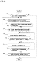
- FIG. 4 shows a flow of a shift control process executed by the shift controller in the first embodiment. Below, based on FIG. 4 , a description is given of each step representing a shift control processing configuration.
- step S1 it is determined whether or not a downshift request from a high gear stage to a low gear stage has been generated.
- YES downshift request present
- NO no downshift request
- the downshift request is output, on the shift map(not shown) which is set based on the accelerator opening and the vehicle speed, when an operating point determined by the accelerator opening and the vehicle speed crosses a downshift line.
- step S2 following the determination that the downshift request is present in step S1, the coupling sleeve 8f of the engagement clutch 8c starts a stroke drive by the first electric actuator 41. Subsequently to the coupling sleeve being displaced immediately before engagement position of the engagement clutch 8c, control proceeds to step S3.
- a position immediately before engagement of the engagement clutch 8c is intended to refer to a position in which the tip position of the spline portion 8fa on the clutch hub side of the coupling sleeve 8f into which the clutch gear 8d fits is positioned immediately before the overlapping with the synchro-teeth 8ga of the synchronizer ring 8g.
- the position in which the distance between the clutch hub side tip of the spline portion 8fa and the synchro-teeth 8ga assumes a very small predetermined value refers to the "position immediately before engagement of the engagement clutch 8c".
- step S4 following the determination that the sleeve position is equal to the position immediately before engagement, a target differential speed to impart a predetermined differential rotation speed is set between the rotation speed of the cutch gear 8d and the rotation speed of the cutch hub 8e. Then control proceeds to step S5.
- the "target differential rotation speed to impart a predetermined differential rotation speed” is intended to refer to a very small rotational speed difference which would not remain the clutch teeth 8ea of the clutch hub 8e and the spline portion 8fa of the coupling sleeve 8f to be opposed to each other, when the coupling sleeve 8f being engaged with the clutch gear 8d will engage with the clutch hub 8e due to a stroke drive.
- the rotational speed difference is set such that, even when the clutch teeth 8ea and the spline 8fa are opposed to each other, the relative position of both components is shifted promptly to engage or mesh each other.
- the target differential speed is set, with reference to a map shown in FIG. 5 , according to a vehicle speed detected by a vehicle speed sensor 22 and vehicle acceleration or vehicle deceleration detected by a longitudinal acceleration sensor 25.
- the rotation speed of the clutch gear 8d representative of a clutch input rotation speed is set to be higher than the rotation speed of the clutch hub 8e representative of the clutch output rotation speed.
- the target differential rotation speed is set greater.
- the target differential rotation speed is set such that the rotation speed of the clutch gear 8d will be lower than the rotation speed of the clutch hub 8e.
- the target differential rotation speed is set greater.
- step S5 following the target differential rotation speed setting in step S4, the rotation speed (motor rotation speed)of the driving motor generator 2representative of the input rotation speed of the automatic transmission is controlled, and control proceeds to step S6.
- the input-side rotation speed of the engagement clutch 8c changes, and the differential rotation speed (difference in rotation speed between the rotation speed of the cutch gear 8d and the rotation speed of the cutch hub 8e) at the engagement clutch 8c will be controlled.
- the motor speed control is performed by a feedback control based on the detected values of the motor rotation speed sensor 33 and transmission output speed sensor 34.
- step S7 following the determination of the actual rotational speed difference being equal to the target difference rotation speed in step S6, in the engagement clutch 8c, the coupling sleeve 8f is allowed to stroke driven by the first electric actuator 41. Then, after the coupling sleeve 8f is displaced to a position of meshing with the clutch hub 8e, control proceeds to step S8.
- step S9 following the determination of the sleeve position being equal to the engagement position in step S8, the target differential speed for engaging the clutch 8c is set to zero, and at the same time, the motor speed control is performed to achieve the target motor differential rotation speed. Subsequently, control ends.
- FIG. 6 is a time chart which shows, in the electric vehicle equipped with the control device of the first embodiment during downshifting, each characteristic including an accelerator pedal opening, a target motor rotation speed, a target input rotation speed of the engagement clutch, a target output rotation speed of the engagement clutch, and a coupling sleeve position, respectively.
- each characteristic including an accelerator pedal opening, a target motor rotation speed, a target input rotation speed of the engagement clutch, a target output rotation speed of the engagement clutch, and a coupling sleeve position, respectively.
- step S1 of the flowchart shown in FIG. 4 control proceeds to step S2.
- the coupling sleeve 8f of the engagement clutch 8c is stroke driven by the first electric actuator 41, and the coupling sleeve 8f is displaced to a position until just before engagement with the clutch hub 8e.
- step S3 when the coupling sleeve 8f has reached the position immediately before engagement, control proceeds through step S3 to S4, in which the target differential rotation speed of the engagement clutch 8c is set to a predetermined differential rotation speed imparting value. Furthermore, in accordance with the target differential speed, the target motor rotational speed of the driving motor generator 2 is set to achieve the target differential rotation speed.
- the target motor rotation speed is set such that the motor rotation speed representative of the automatic transmission input rotation speed exceeds the automatic transmission output rotation speed in order for the motor rotation speed to exceed the output rotation speed (cumulative value obtained by multiplying the automatic transmission input rotation speed by gear ratio of the automatic transmission 3). Subsequently, control proceeds to step S5 to thereby execute the motor rotation speed control.
- step S6 when the differential rotation occurs between a target value of cutch input rotation speed of the engagement clutch 8c and a target value of the cutch output rotation speed, and, at time t4, when it is determined that the actual differential rotation speed has reached the target differential rotation speed, control proceeds through step S6, step S7. Subsequently, the coupling sleeve 8f is stroke driven again to start the displacement toward the engaged position.
- the actual differential speed is calculated by subtracting the rotation speed of the transmission output shaft 7 detected by the transmission output speed sensor 34 from the rotation speed of transmission input shaft 6 detected by the motor rotation speed sensor 33.
- the coupling sleeve 8f is stroke driven, the relative positional relationship between the spline portion 8fa and clutch teeth 8ea continues to change until engagement with the clutch hub 8e so that the tip of the spline portion 8fa may avoid collision with the tip of the clutch teeth 8ea.
- the coupling sleeve 8f and the clutch hub 8e can be engaged smoothly so that it is possible to prevent the occurrence of meshing failure in which both components do not mesh with each other. Also, since the meshing failure is not generated, a wasted time such as redoing of the fastening operation would not be generated. Thus, it is possible to shorten the shift time.
- step S8 and step S9 control proceeds through step S8 and step S9, and the target differential rotation speed of the engagement clutch 8c will be set to zero. Also, in response to the target differential rotation speed being set to zero, in order to achieve the target differential rotation speed, the target motor rotation speed of the driving motor generator 2 is set.
- the motor rotation speed representative of the transmission input speed has been set to the differential rotation higher than the transmission output rotation speed, the motor rotation speed will be reduced to match the output rotation speed (value of transmission input rotation speed multiplied by the gear ratio after shifting of the automatic transmission 3). Accordingly, the motor rotation speed control is executed.
- the coupling sleeve 8f of the engagement clutch 8c has been stroke driven previously until a position immediately before engagement.
- the motor rotation speed control is carried out to reach the target differential rotation speed.
- the friction clutch 9c that is being in frictional engagement is changed to be slip-engaged, and then the engagement operation of engagement clutch 8c is carried out.
- the rotation speed of the clutch gear 8d representative of the input rotation speed is set higher than the rotation speed of the clutch hub 8e representative of the output rotation speed.
- the rotation speed of the clutch gear 8d is set lower than the rotation speed of the clutch hub 8e.
- the target differential rotation speed is set greater.
- the target differential rotation speed is greater, the relative displacement speed between the tip of the spline portion 8fa of the coupling sleeve 8f and the tip of the clutch teeth 8ea of the clutch hub 8e is faster, it is possible to perform the engagement operation in the engagement clutch 8c quickly.
- the target differential rotation speed is smaller, it is possible to suppress a shock (engagement shock) when engaging the coupling sleeve 8f with the clutch hub 8e.
- the automatic transmission control device has been described above based on the first embodiment. However, the detailed configurations are not limited to this embodiment.
- the automatic transmission 3 has an engagement clutch 8c and a friction clutch 9c.
- the automatic transmission may include only an engagement clutch as engaging element.
- the engagement clutch 8c includes a synchronization mechanism.
- the present invention is applicable to a so-called dog clutch which is not provided with such synchronization mechanism.
- the engagement clutch 8c is coupled with the clutch gear 8d representative of a first engagement member meshed with the clutch hub 8e representative of a second engagement member via the coupling sleeve 8f.
- the configuration is not limited to this example.
- the first engagement member may be directly meshed with the second engagement member.
- the "position immediately before the engagement of the engaging clutch 8c" is intended to describe a position of the clutch hub side tip of the spline portion 8fa of the coupling sleeve 8f assumes a position immediately before overlapping when viewed in the axial direction with the synchro-tooth 8ga of the synchronizer ring 8g.
- the configuration is not limited to this example.
- the position in which a gap between the first engagement member and the second engagement member assumes a negligible, predetermined value may be referred to as the "position immediately before the engagement of the engaging clutch 8c".
- the " position immediately before the engagement of the engaging clutch 8c" is defined as such a position in which the first engagement member (or a member such as the coupling sleeve 8f which is subject to meshing with the first engagement member) and the second engagement member may be meshed in a very short time.
- the driving source is comprised of only a driving motor/generator 2.
- the driving force is not limited to this configuration.
- the driving force may include both a motor and an engine, or may be comprised of an engine only.
Landscapes
- Engineering & Computer Science (AREA)
- General Engineering & Computer Science (AREA)
- Mechanical Engineering (AREA)
- Control Of Transmission Device (AREA)
- Hydraulic Clutches, Magnetic Clutches, Fluid Clutches, And Fluid Joints (AREA)
- Hybrid Electric Vehicles (AREA)
- Electric Propulsion And Braking For Vehicles (AREA)
Description
- The present invention relates to an automatic transmission control device equipped with an automatic transmission having an engagement clutch disposed in a vehicle drive system and performing a meshing engagement as an engagement element.
- Conventionally, in an automatic transmission having an engagement clutch which is subject to meshing engagement, such an automatic transmission control device is known in which an input side rotation speed of the engagement clutch is synchronized with and output side rotation speed thereof (for example, see Patent Document 1).
- Patent Document 1:
JP 2001-90826 A - Prior
art document EP 0 641 959 A2 suggests an automated mechanical transmission control system and method which are configured to course for both up shifts and downshifts the jaw clutch engagement when an input shaft is rotating at a speed equal to or slightly larger than an exact synchronous speed. - Document
WO 2010/119 504 A1 describes a drive controller for a vehicle having a control means allowing first and second engagement elements to engage under such a state that a differential rotation in a predetermined direction is imparted previously between said first and second engagement elements. - Prior art document
WO 2013/076218 A1 discloses a method and an apparatus for controlling the engagement of an input gear with an output gear which are configured in order to avoid the necessity for a mechanical synchromesh in order to smooth a transition from a low range to a high range and vice versa. - However, in the conventional control device for the automatic transmission, at the time of coupling the engagement clutch, due to synchronization process between the input side rotation speed and the output side rotation speed, depending on the positional relation of an input side clutch gear relative to an output side clutch hub during synchronization, a situation may arise in which the engagement clutch cannot be coupled or engaged so that so-called "meshing failure" occurs.
- More specifically, when the input side clutch teeth are synchronized in rotation speed with the output side clutch teeth in opposing state, the opposing clutch teeth are in contact with each other and thus are incapable of being meshed. In order to cope with this situation, it is necessary to temporarily generating a differential rotation to thereby shift the relative position of the opposing teeth and resume a meshing operation. Thus, a problem occurs that the time until engagement completion is prolonged.
- The present invention has been made in consideration of the above problems, and, aims to provide an automatic control device in which the meshing failure of the engagement clutch may be prevented from occurring and the time until engagement completion may be prevented from being prolonged.
- The object underlying the present invention is achieved by an automatic transmission control device according to
independent claim 1. Preferred embodiments are defined in the respective dependent claims. - In order to achieve the aim described above, in automatic transmission control device according to the present invention, an automatic transmission having an engagement clutch disposed in a vehicle drive system and operative in meshing engagement as a coupling element and a shift controller that executes a shift control of the automatic transmission are respectively provided.
- Further, the engagement clutch is provided with a first engagement member connected to a transmission input shaft and a second engagement member connected to a transmission output shaft and being capable of meshing with the first engagement member.
- The shift controller is configured to set a target differential rotation speed when engaging the engagement clutch for shifting such that when the first engagement member and the second engagement member mesh each other a predetermined differential rotation is imparted between an input rotation speed representative of the rotation speed of the first engagement member and an output rotation speed representative of the rotation speed of the second engagement member. The magnitude of the target differential rotation speed is set according to the magnitude of the acceleration of the vehicle such that, as the magnitude of the acceleration of the vehicle increases, the target differential rotation speed is set larger.
- Therefore, in the automatic transmission control device according to the present invention, when engaging the engagement clutch for shifting, the shift controller is configured, when the first engagement member and the second engaging member mesh with each other, such that a target differential rotation speed is set to provide a predetermined differential rotation of the engagement clutch between the input rotation speed and the output rotation speed.
- Thus, at the timing when the first and the second engagement members mesh each other, the relative position between the teeth of the first engagement member and the teeth of the second engagement member continues to change. Therefore, even when the teeth of the first engagement member and the teeth of the second engagement member are opposed to each other, the relative positional relationship between both will be shifted quickly. Therefore, the situation may be avoided in which the teeth of the first engagement member and the teeth of the second engagement member continue to be in contact while facing each other so that the meshing failure in which the first and the second engagement members fail to mesh each other may be prevented from occurring.
- Also, since it is possible to prevent the occurrence of the meshing failure, the trouble may be avoidable to resume meshing operation after shifting the relative position between the first and the second engagement members. As a result, it is possible to prevent the time until engagement completion of the engagement clutch from being prolonged.
-
-
FIG. 1 is an overall system block diagram showing a drive system configuration and a control system configuration of an electric vehicle (an example of an electrically driven vehicle) to which an automatic transmission control device of a first embodiment is applied; -
FIG. 2 is a control block diagram showing a detailed configuration of a shift control system of the first embodiment; -
FIG. 3A is an explanatory view showing an essential part cross section of the engagement clutch of the first embodiment; -
FIG. 3B is a view showing the essential part shown inFIG. 3A as seen from the upper side of the engagement clutch shown inFigure 3A for illustrating a state immediately before engagement; -
FIG. 3C is a view showing the essential part shown inFIG. 3A as seen from the upper side of the engagement clutch shown inFigure 3A for illustrating a state in which a chamfer portion is contact during the rotational synchronization; -
FIG. 3D is a view showing the essential part shown inFIG. 3A as seen from the upper side of the engagement clutch shown inFigure 3A for illustrating a state in which a chamfer portion is free from contact during the rotational synchronization; -
FIG. 3E is a view showing the essential part shown inFIG. 3A as seen from the upper side of the engagement clutch shown inFigure 3A for illustrating a state of completion of rotational synchronization; -
FIG. 4 is a flowchart showing a flow of shift control process executed by a shift controller in the first embodiment; -
FIG. 5 is a diagram showing an example of a target differential rotation speed setting map; and -
FIG. 6 is a time chart which shows, in the electric vehicle equipped with the control device of the first embodiment during downshifting, each characteristic including an accelerator pedal opening, a target motor rotation speed, a target input rotation speed of the engagement clutch, a target output rotation speed of the engagement clutch, and a coupling sleeve position, respectively. - Below, a description is given of an embodiment for implementing a control device of an automatic transmission according to the present invention with reference to a first embodiment shown in the accompanying drawings.
- First, a description is made of the configuration.
- The configuration of a shift control device mounted in an electric vehicle (an example of a vehicle) in the first embodiment is described in "the overall system configuration", "detailed configuration of a shift control system" and "shift control processing configuration", separately.
-
FIG. 1 shows a drive system configuration and a control system configuration of an electric vehicle to which the shift control device in the first embodiment is applied. Below, with reference toFIG. 1 , the overall system configuration is described. - As the drive system configuration of the electric vehicle (vehicle), as shown in
FIG. 1 , adriving motor generator 2, anautomatic transmission 3, and adrive wheel 14 are provided. - The
driving motor generator 2 is of a permanent magnet synchronous motor of three-phase alternating current and serves as a driving source for travel of the electric vehicle. Thedriving motor generator 2, when a positive torque (driving torque) command is output to the inverter (not shown) from amotor controller 28, generates a driving torque using a discharge power from a high voltage battery (not shown) so as to carry out a driving operation to drive the drive wheels 14 (power running). On the other hand, when a negative torque (generation torque) command is output to the inverter from themotor controller 28, a power generating operation for converting rotational energy from thedrive wheels 14 into electrical energy is performed, and the power thus generated is used as charging electric power in the high voltage battery (regeneration).
Then, a motor shaft of thedriving motor generator 2 is connected to atransmission input shaft 6 of theautomatic transmission 3. - The
automatic transmission 3 is a constant mesh-type stepped transmission which transmits power in one of two gear pairs of different transmission or speed ratios, in which two stage shifting are performed in which a high gear stage (high speed stage) with a low speed reduction ratio and a low gear stage with high speed reduction ratio. Theautomatic transmission 3 is used for gear shifting when outputting a motor power by passing from thedriving motor generator 2 through atransmission input shaft 6 and atransmission output shaft 7 and is configured by a lowside transmission mechanism 8 for realizing a low shift stage and a highside transmission mechanism 9 for realizing a high shift stage. Note that thetransmission input shaft 6 and thetransmission output shaft 7 are disposed parallel to each other. - The low
side shift mechanism 8 is used for selecting a low-side transmission path at the time of outputting the motor power and is disposed on thetransmission output shaft 7. The lowside shift mechanism 8 is made up of an engagement clutch 83 (meshing element) which performs a meshing engagement/release of agear 8a with respect to thetransmission output shaft 7 in order for the low speed stage gear pair 80 (gear 8a,gear 8b) to drivingly connect between thetransmission input shaft 6 and thetransmission output shaft 7. Here, the low speed stage gear pair 80 is composed of thegear 8a rotatably supported on thetransmission output shaft 7 and thegear 8b which is meshed with thegear 8a and rotates jointly with thetransmission input shaft 6. - The high-
side transmission mechanism 9 is intended, when outputting the motor power, for selecting a high-side transmission path and is arranged on thetransmission input shaft 6. This high-speedside shift mechanism 9 is made up of afriction clutch 9c (engagement element) which performs a frictional engagement/release of agear 9a with respect to thetransmission input shaft 6 in order for the high speed stage gear pair 90 (gear 9a,gear 9b) to drivingly connect between thetransmission input shaft 6 and thetransmission output shaft 7. Here, the high speed stage gear pair is composed of thegear 9a rotatably supported on thetransmission input shaft 6 and thegear 9b which is meshed with thegear 9a and rotates jointly with thetransmission output shaft 7. - The
transmission output shaft 7, with agear 11 fixed thereto, and through a final drive gear set composed of thegear 11 and agear 12 meshed therewith, is configured to drivingly connect adifferential gear unit 13 to thetransmission output shaft 7. Further, adrive shaft 16 connected to adrive wheel 14 is coupled to thedifferential gear unit 13. Thus, the motor power of the drivingmotor generator 2, which has reached thetransmission output shaft 7 is configured to be further transmitted via the final drive gear set 11, 12, thedifferential gear unit 13, and the left andright drive shaft 16 to the drive wheels 14 (only one of the drive wheels is shown inFIG. 1 ). - Further, a
parking gear 17 is fixed to thetransmission output shaft 7 in the side opposite to thegear 11, and aparking pole 1 8 is arranged provided on a transmission case (not shown) so as to be able to be meshed with theparking gear 17. In other words, when selecting a P range position, by allowing theparking pole 18 to mesh with theparking gear 17 by the first electric actuator use commonly for theengagement clutch 8c, thetransmission output shaft 7 is fixed to the transmission case so as to be unrotatable. - As the control system configuration of the electric vehicle, as shown in
FIG. 1 , ashift controller 21, avehicle speed sensor 22, anaccelerator opening sensor 23, abrake stroke sensor 24, alongitudinal acceleration sensor 25, aslider position sensor 26, asleeve position sensor 27, a motorrotation speed sensor 33, a transmission outputrotation speed sensor 34, and the like are provided. In addition, amotor controller 28, abrake controller 29, anintegrated controller 30, aCAN communication line 31, and arange position switch 32 are provided. - The
shift controller 21 is composed of a microcomputer provided with a CPU (Central Processing Unit), a ROM (Read Only Memory), a RAM (Random Access Memory), a backup memory, and an I/O interface. Theshift controller 21 outputs a shift command or request based on a shift map (not shown), and is further configured, when upshifting to a high gear stage in a state of low gear stage with the engaging clutch 8c in engaged state and the friction clutch 9c released, to perform a switching control to release the engaging clutch 8c and to frictionally connect thefriction clutch 9c. Also, when downshifting to low gear stage in a state in which the engaging clutch 8c is released and the friction clutch 9c is frictionally engaged, theshift controller 21 performs a switching control to carry out meshing engagement of theengagement clutch 8c and release of the friction clutch 93. Further, at the time of downshifting, a shift control processing is executed as described below and the meshing engagement of theengagement clutch 8c will be controlled. - The
range position switch 32 is intended to be a switch which detects a range position of theautomatic transmission 3, which has been selected in response to a driver's selecting operation with respect to a select lever (not shown). The positions detectable are P range (i.e. parking, non-driving, or parking range9, N range (i.e. neutral range), D range (i.e. drive range, forward driving range), R range (i.e. reverse range, reverse driving range), and the like. - The motor
rotation speed sensor 33 is provided for detecting an output rotation speed of the drivingmotor generator 2. In other words, the rotation speed of thetransmission input shaft 6 is detected. That is, the rotation speed of the driving motor generator 2 (motor speed) corresponds to an input rotation speed (hereinafter, referred to as "clutch input rotation speed") to the engagement elements (engagement clutch 8c,friction clutch 9c) provided in the automatic transmission. Thus, the clutch input rotation speed is detected by the motorrotation speed sensor 33. - The transmission output
rotation speed sensor 34 is provided for detecting an output rotation speed of theautomatic transmission 3. In other words, the rotation speed of thetransmission output shaft 7 is detected. That is, the rotation speed of thetransmission output shaft 7 corresponds to an output rotation speed (hereinafter, referred to as "clutch output rotation speed") of the engagement elements (engagement clutch 8c,friction clutch 9c) provided in the automatic transmission. The transmission outputrotation speed sensor 34 detects the clutch output rotation speed. -
FIG. 2 shows a detailed configuration of a shift control system of the first embodiment.FIG. 3 is an explanatory diagram of the engagement clutch of the first embodiment. Below, with reference toFIGS. 2 and3 , a detailed configuration of the shift control system in the first embodiment is described. - As a configuration of the shift control system of the control system of the electric vehicle, as shown in
FIG. 2 , anengagement clutch 8c, afriction clutch 9c, aparking gear 17, a drivingmotor generator 2, ahydraulic brake 15, ashift controller 21 are provided. Specifically, theengagement clutch 8c, thefriction clutch 9c, the drivingmotor generator 2, and thehydraulic brake 15 are subject to control, and depending on conditions, control is executed based on a request from theshift controller 21. - The
engagement clutch 8c is constructed in a clutch of synchronous meshing type, and includes aclutch gear 8a(first engagement member) provided on thegear 8d and a clutch hub (second engagement member) 8e attached to thetransmission output shaft 7, and acoupling sleeve 8f (seeFIG. 1 ). Further, by driving in stroke thecoupling sleeve 8f by the firstelectric actuator 41, meshing engagement/release between theclutch gear 8d and theclutch hub 8e is performed via thecoupling sleeve 8f. Note that, since thegear 8a is meshed with thegear 8b jointly rotatable with thetransmission input shaft 6, theclutch gear 8d provided on thegear 8a is coupled to thetransmission input shaft 6. In other words, when theclutch gear 8d and theclutch hub 8e are engaged by meshing, thetransmission input shaft 6 and thetransmission output shaft 7 are coupled. - The meshing engagement or release of the
engagement clutch 8c is determined by the position of thecoupling sleeve 8f. Thus, theshift controller 21 reads the value of thesleeve position sensor 27 and is provided with a first position servo controller 51 (for example, position servo system with PID control) which provides a current to the firstelectric actuator 41, so that the position of thecoupling sleeve 8f is located in the meshing engagement position or the release position. - Further, when the
coupling sleeve 8f is in meshed engagement position shown inFIG. 1 , where thecoupling sleeve 8f is meshed with the outer periphery clutch teeth of bothclutch gear 8d and those of theclutch hub 8e, thegear 8a is drivingly connected to thetransmission output shaft 7. On the other hand, when thecoupling sleeve 8f is in a non-meshing position with the outer periphery clutch teeth of one of theclutch gear 8d and theclutch hub 8e, thegear 8a is released from thetransmission output shaft 7. - Furthermore, with reference to
FIG. 3A to FIG. 3E , a description is added of the synchronization mechanism of theengagement clutch 8c. Thecoupling sleeve 8f is formed in a cylindrical shape with both ends open and provided at its inner periphery with a plurality of spline portions 8fa constantly fit with clutch teeth (not shown) of theclutch gear 8d (seeFIG. 1 ). Further, while maintaining a fitting state between the clutch teeth of theclutch gear 8d and the spline portions 8fa, thecoupling sleeve 8f is supported movably axially, i.e., in the left-right direction inFIG. 3A . The axial movement of thecoupling sleeve 8f is made by driving the first electric actuator 41 (seeFIG. 2 ). - The
clutch hub 8e is formed with a plurality of clutch teeth 8ea on the outer periphery thereof, which may be fit into the spline portions 8fa formed on the inner periphery of thecoupling sleeve 8f. That is, the clutch teeth 8ea of theclutch hub 8e will be engageable with the clutch teeth of theclutch gear 8d (not shown) via thecoupling sleeve 8f.
Furthermore, in theclutch hub 8e, the outer periphery of a tapered cone portion 8eb is fitted with asynchronizer ring 8g movably in the axial direction. - The
synchronizer ring 8g is formed with a plurality of synchro-teeth 8ga which can mesh with a plurality of the spline portions 8fa of thecoupling sleeve 8f and key grooves 8gc which constantly mesh withkeys 8h provided on thecoupling sleeve 8f. A gap is provided between the key 8h and the key groove 8gc. Thesynchronizer ring 8g is configured to be movable in the rotational direction relative to thecoupling sleeve 8f by the amount of the gap between the key 8h and the key groove 8gc. - Now, a description will be given of the synchronizing operation of the synchronization mechanism with respect to the
engagement clutch 8c when changing from a released state to the engaged or meshed connection. In theengagement clutch 8c, when changing to the engaged connection from the released state, thecoupling sleeve 8f presses thesynchronizer ring 8g in the axial direction so as to approach theclutch hub 8e. As a result, due the resulting friction force between thesynchronizer ring 8g and the cone portion 8eb, thecoupling sleeve 8f and theclutch hub 8e are connected to rotate in synchronization. - In other words, by moving the
coupling sleeve 8f by the first electric actuator 41 (seeFIG. 2 ) axially, as shown inFIG. 3A , together with the key 8h, in a direction to be close to theclutch hub 8e, thesynchronizer ring 8g is pressed against the cone portion 8eb. - When the
synchronizer ring 8g is pressed against the cone portion 8eb, because a relative rotation is occurring between both components, thesynchronizer ring 8g rotates only by the gap or clearance of the key groove 8gc shown inFIG. 3B . Thus, a chamfer portion 8gb of the synchro-teeth 8ga of thesynchronizer ring 8g and a chamfer portion 8fb of the spline portion 8fa of thecoupling sleeve 8f, as shown inFIG. 3B , are brought into an index state, i.e., facing each other when viewed in the axial direction. - By moving the
coupling sleeve 8f further in the direction of theclutch hub 8e side from the index state, as shown inFIG. 3C , both chamfer portions 8fb, 8gb are brought into contact each other. Thus, thesynchronizer ring 8g further presses the cone portion 8eb to generate the friction torque so that thesynchronizer ring 8g, thecoupling sleeve 8f, and theclutch hub 8e are synchronized. At this time, thesynchronizer ring 8g rotates in the circumferential direction such that the spline portion 8fa is to mate with synchro-teeth 8ga,. - As shown in
Figure 3D , when thecoupling sleeve 8f passes a reverse taper angle 8gd of thesynchronizer ring 8g, the rotation synchronization between thecoupling sleeve 8f andsynchronizer ring 8g is established.
When this rotation synchronization is established, while the friction torque between thesynchronizer ring 8g and the cone portion 8eb disappears, thecoupling sleeve 8f moves further axially while holding thekey 8h stand-by. As a result, the spline portion 8fa of thecoupling sleeve 8f pushes aside the clutch teeth 8ea of theclutch hub 8e, so as to be meshed with the clutch teeth 8ea of theclutch hub 8e, as shown inFIG. 3E . Thus, theengagement clutch 8c is brought into a meshed engagement state. - The friction clutch 9c includes a driven
plate 9d which rotates together with thegear 9a, and adrive plate 9e which rotates together with the transmission input shaft 6 (seeFIG. 1 ). Further, by driving aslider 9f to impart a pressing force to bothplates electric actuator 42, the frictional engagement/release is performed. - The transmission torque capacity of the
frictional clutch 9c is determined by a position of theslider 9f. Also, theslider 9f is a screw mechanism, so that, when the input of the secondelectric actuator 42 is 0 (zero), the position is configured to be held. Theshift controller 21 reads the value of theslider position sensor 26 and is provided with a second position servo controller 52 (for example, position servo system by PID control) so that a slider position for obtaining a desired transmission torque capacity may be achieved. - Further, the friction clutch 9c rotates jointly with the
transmission input shaft 6, and drivingly connects thegear 9a to thetransmission input shaft 6 when frictionally engaged, and, when releasing, separates the drive connection between thegear 9a and thetransmission input shaft 6. - The
parking gear 17, when selecting P range position (non-driving range position), the firstelectric actuator 41 which also serves for theengagement clutch 8c causes theparking pawl 18 to be meshed, so that thetransmission output shaft 7 is fixed to or non-rotatable relative to the case. That is, the firstelectric actuator 41 manages three operational positions selectively, i.e., the engagement position of theengagement clutch 8c, a non-engagement position of theengagement clutch 8c, and the engagement position of theparking gear 17. - The
motor generator 2 is placed under a torque control or rotation speed control by amotor controller 28 which receives a command output from theshift controller 21. In other words, when themotor controller 28 receives a motor torque request, control, or a input-output rotation synchronization request from theshift controller 21, in response to these requests, the drivingmotor generator 2 will be placed under the torque control or the rotation speed control. - The
hydraulic brake 15 is increased in the braking engagement force by a pump-up operation by a brake hydraulic pressure actuator (not shown) which receives a driving request from thebrake controller 29 which in turn receives a request from theshift controller 21. -
FIG. 4 shows a flow of a shift control process executed by the shift controller in the first embodiment. Below, based onFIG. 4 , a description is given of each step representing a shift control processing configuration. - Note that this process is executed in the
automatic transmission 3 in response to a shift request being made. - In step S1, it is determined whether or not a downshift request from a high gear stage to a low gear stage has been generated. When YES (downshift request present), control proceeds to step S2, while, if NO (no downshift request), the shift control process shown in
FIG. 4 will not be performed and control ends. - Here, the downshift request is output, on the shift map(not shown) which is set based on the accelerator opening and the vehicle speed, when an operating point determined by the accelerator opening and the vehicle speed crosses a downshift line.
- In step S2, following the determination that the downshift request is present in step S1, the
coupling sleeve 8f of theengagement clutch 8c starts a stroke drive by the firstelectric actuator 41. Subsequently to the coupling sleeve being displaced immediately before engagement position of theengagement clutch 8c, control proceeds to step S3. - Here, "a position immediately before engagement of the
engagement clutch 8c", is intended to refer to a position in which the tip position of the spline portion 8fa on the clutch hub side of thecoupling sleeve 8f into which theclutch gear 8d fits is positioned immediately before the overlapping with the synchro-teeth 8ga of thesynchronizer ring 8g. In other words, the position in which the distance between the clutch hub side tip of the spline portion 8fa and the synchro-teeth 8ga assumes a very small predetermined value refers to the "position immediately before engagement of theengagement clutch 8c". - In step S3, following the stroke engagement of the coupling sleeve8f of the coupling in step S2, the determination is made whether or not the position of the
coupling sleeve 8f has reached a position immediately before engagement. If YES (i.e., sleeve position = position immediately before engagement), control proceeds to step S4. If NO (i.e., sleeve position ≠ position immediately before engagement), it is determined that thecoupling sleeve 8f is insufficient in stroke drive, and process returns to step S2. - Here, the position of the coupling sleeve 8Fis detected by the
sleeve position sensor 27. Further, once thecoupling sleeve 8f has reached the position before engagement, this position is maintained. - In step S4, following the determination that the sleeve position is equal to the position immediately before engagement, a target differential speed to impart a predetermined differential rotation speed is set between the rotation speed of the
cutch gear 8d and the rotation speed of thecutch hub 8e. Then control proceeds to step S5. - Here, the "target differential rotation speed to impart a predetermined differential rotation speed", is intended to refer to a very small rotational speed difference which would not remain the clutch teeth 8ea of the
clutch hub 8e and the spline portion 8fa of thecoupling sleeve 8f to be opposed to each other, when thecoupling sleeve 8f being engaged with theclutch gear 8d will engage with theclutch hub 8e due to a stroke drive. In other words, the rotational speed difference is set such that, even when the clutch teeth 8ea and the spline 8fa are opposed to each other, the relative position of both components is shifted promptly to engage or mesh each other. - In addition, the target differential speed is set, with reference to a map shown in
FIG. 5 , according to a vehicle speed detected by avehicle speed sensor 22 and vehicle acceleration or vehicle deceleration detected by alongitudinal acceleration sensor 25. - More specifically, when the vehicle is accelerating, the rotation speed of the
clutch gear 8d representative of a clutch input rotation speed is set to be higher than the rotation speed of theclutch hub 8e representative of the clutch output rotation speed. In addition, as the vehicle acceleration increases, the target differential rotation speed is set greater.
Further, when the vehicle is decelerating, the target differential rotation speed is set such that the rotation speed of theclutch gear 8d will be lower than the rotation speed of theclutch hub 8e. In addition, as the vehicle deceleration increases, the target differential rotation speed is set greater. - In step S5, following the target differential rotation speed setting in step S4, the rotation speed (motor rotation speed)of the driving motor generator 2representative of the input rotation speed of the automatic transmission is controlled, and control proceeds to step S6.
- Thus, the input-side rotation speed of the
engagement clutch 8c changes, and the differential rotation speed (difference in rotation speed between the rotation speed of thecutch gear 8d and the rotation speed of thecutch hub 8e) at theengagement clutch 8c will be controlled. Note that the motor speed control is performed by a feedback control based on the detected values of the motorrotation speed sensor 33 and transmissionoutput speed sensor 34. - In step S6, followed the motor speed control in step S5, it is determined whether or not the actual rotation speed difference of the
engagement clutch 8c has reached the target rotation speed difference that was set in step S4. If YES (actual rotation speed difference = target differential rotation speed), the control proceeds to step S7. If NO (the actual rotation speed difference ≠ target difference rotation speed), control returns to step S5. - In step S7, following the determination of the actual rotational speed difference being equal to the target difference rotation speed in step S6, in the
engagement clutch 8c, thecoupling sleeve 8f is allowed to stroke driven by the firstelectric actuator 41. Then, after thecoupling sleeve 8f is displaced to a position of meshing with theclutch hub 8e, control proceeds to step S8. - In step S8, following the stroke drive of the
coupling sleeve 8f in step S7, it is determined whether or not the position of thecoupling sleeve 8f has reached the engagement position. If YES (the sleeve position = meshing position), control proceeds to step S9. If NO (sleeve position # engagement position), it is determined that there is not enough stroke drive for thecoupling sleeve 8f, control returns to step S7.
The position of thecoupling sleeve 8f is detected by thesleeve position sensor 27. - In step S9, following the determination of the sleeve position being equal to the engagement position in step S8, the target differential speed for engaging the clutch 8c is set to zero, and at the same time, the motor speed control is performed to achieve the target motor differential rotation speed. Subsequently, control ends.
- Now, a description is given of the "engagement clutch engagement operation" in the automatic transmission control device in the first embodiment.
-
FIG. 6 is a time chart which shows, in the electric vehicle equipped with the control device of the first embodiment during downshifting, each characteristic including an accelerator pedal opening, a target motor rotation speed, a target input rotation speed of the engagement clutch, a target output rotation speed of the engagement clutch, and a coupling sleeve position, respectively. Below, with reference toFIG. 6 , a description is given of the engagement clutch engagement operation in the first embodiment. - Now, it is assumed that, during travel with the high gear stage with the
engagement cutch 8c released and the friction clutch 9c friction engaged, at time t shown inFIG. 6 , due to rapid increase of the accelerator opening, a shift request for a low gear stage occurs. - Along with the output of the shift request, it is determined YES in step S1 of the flowchart shown in
FIG. 4 , control proceeds to step S2. As a result, thecoupling sleeve 8f of theengagement clutch 8c is stroke driven by the firstelectric actuator 41, and thecoupling sleeve 8f is displaced to a position until just before engagement with theclutch hub 8e. - At time t2, when the
coupling sleeve 8f has reached the position immediately before engagement, control proceeds through step S3 to S4, in which the target differential rotation speed of theengagement clutch 8c is set to a predetermined differential rotation speed imparting value. Furthermore, in accordance with the target differential speed, the target motor rotational speed of the drivingmotor generator 2 is set to achieve the target differential rotation speed. - Note that, since the vehicle is accelerating here, the target motor rotation speed is set such that the motor rotation speed representative of the automatic transmission input rotation speed exceeds the automatic transmission output rotation speed in order for the motor rotation speed to exceed the output rotation speed (cumulative value obtained by multiplying the automatic transmission input rotation speed by gear ratio of the automatic transmission 3). Subsequently, control proceeds to step S5 to thereby execute the motor rotation speed control.
- At time t3, when the differential rotation occurs between a target value of cutch input rotation speed of the
engagement clutch 8c and a target value of the cutch output rotation speed, and, at time t4, when it is determined that the actual differential rotation speed has reached the target differential rotation speed, control proceeds through step S6, step S7. Subsequently, thecoupling sleeve 8f is stroke driven again to start the displacement toward the engaged position. Here, the actual differential speed is calculated by subtracting the rotation speed of thetransmission output shaft 7 detected by the transmissionoutput speed sensor 34 from the rotation speed oftransmission input shaft 6 detected by the motorrotation speed sensor 33. - In a state where the
engagement clutch 8c is rotated with a predetermined differential rotation, when thecoupling sleeve 8f is stroke driven, in the position immediately before engagement, even when the tip of the spline portion 8fa of thecoupling sleeve 8f and theclutch hub 8e and the tip of the clutch teeth 8ea are opposite to each other, the opposite state will be eliminated rapidly.
That is, with respect to thecoupling sleeve 8f, since theclutch hub 8e constantly moves relatively, the relative positional relationship between the spline portion 8fa and clutch teeth 8ea changes from moment to moment.
Thus, thecoupling sleeve 8f is stroke driven, the relative positional relationship between the spline portion 8fa and clutch teeth 8ea continues to change until engagement with theclutch hub 8e so that the tip of the spline portion 8fa may avoid collision with the tip of the clutch teeth 8ea. As a result, thecoupling sleeve 8f and theclutch hub 8e can be engaged smoothly so that it is possible to prevent the occurrence of meshing failure in which both components do not mesh with each other.
Also, since the meshing failure is not generated, a wasted time such as redoing of the fastening operation would not be generated. Thus, it is possible to shorten the shift time. - Further, at time t5, when the
coupling sleeve 8f has reached the meshing engagement position, control proceeds through step S8 and step S9, and the target differential rotation speed of theengagement clutch 8c will be set to zero. Also, in response to the target differential rotation speed being set to zero, in order to achieve the target differential rotation speed, the target motor rotation speed of the drivingmotor generator 2 is set.
Here, since the motor rotation speed representative of the transmission input speed has been set to the differential rotation higher than the transmission output rotation speed, the motor rotation speed will be reduced to match the output rotation speed (value of transmission input rotation speed multiplied by the gear ratio after shifting of the automatic transmission 3). Accordingly, the motor rotation speed control is executed. - At time t6 at which both the actual differential rotation speed and the target differential rotation speed have reached zero, it is determined that the meshing engagement of the
engagement clutch 8c has been completed. - In the first embodiment, before setting the target differential rotation speed of the engagement clutch8c, when the downshift request is output, the
coupling sleeve 8f of theengagement clutch 8c has been stroke driven previously until a position immediately before engagement. In other words, after the relative position of thecoupling sleeve 8f engaging with theclutch gear 8d and theclutch hub 8e is place to the position immediately before engagement, the motor rotation speed control is carried out to reach the target differential rotation speed.
Here, in theautomatic transmission 3, when the downshift request is output, first, the friction clutch 9c that is being in frictional engagement is changed to be slip-engaged, and then the engagement operation ofengagement clutch 8c is carried out. At this time, by stroke driving thecoupling sleeve 8f in advance to the position immediately before engagement, it is possible to perform the engagement preparation for engaging the clutch 8c without waiting for the completion of the slip-engagement of thefriction clutch 9c. Thus, it is possible to shorten the time until the meshing engagement of theengagement clutch 8c is completed. Therefore, it is possible to further shorten the shift time. - Also, in the first embodiment, as shown in
FIG. 5 , when the vehicle accelerates, the target differential rotation speed which is set at the time of engagement of theengagement clutch 8c, the rotation speed of theclutch gear 8d representative of the input rotation speed is set higher than the rotation speed of theclutch hub 8e representative of the output rotation speed. In contrast, when the vehicle is decelerating, the rotation speed of theclutch gear 8d is set lower than the rotation speed of theclutch hub 8e. - Therefore, even if a shock is generated when the
engagement clutch 8c is coupled, during vehicle acceleration, the engagement shock occurs on the vehicle acceleration side. When the vehicle decelerates, the engagement shock occurs on the vehicle deceleration side. Therefore, it is possible to suppress discomfort associated with shock. - Moreover, in the present first embodiment, as the vehicle acceleration or deceleration of the vehicle increases, the target differential rotation speed is set greater. Here, as the target differential rotation speed is greater, the relative displacement speed between the tip of the spline portion 8fa of the
coupling sleeve 8f and the tip of the clutch teeth 8ea of theclutch hub 8e is faster, it is possible to perform the engagement operation in theengagement clutch 8c quickly. On the other hand, the target differential rotation speed is smaller, it is possible to suppress a shock (engagement shock) when engaging thecoupling sleeve 8f with theclutch hub 8e. - In other words, by setting greater the target differential rotation speed as the vehicle acceleration or vehicle deceleration is greater, it is possible to respond appropriately to the request for a quick shift speed by allowing engagement of the
engagement clutch 8c easier. Also, by setting the target differential rotation speed smaller as the vehicle acceleration or vehicle deceleration is smaller, it is possible to suppress engagement shock associated with meshing engagement of theengagement clutch 8c. Further, it is possible to suppress the engagement shock which is easily recognizable when gently accelerated or decelerated. - Now, a description is given of effects.
- According to the present invention's automatic transmission control device, the following effects may be obtained.
- (1) An automatic transmission control device provided with an
automatic transmission 3 having anengagement clutch 8c disposed in a vehicle drive system and, when engaged, operative in meshing engagement as a coupling element and ashift controller 21 that executes a shift control of theautomatic transmission 3, wherein theengagement clutch 8c is provided with a first engagement member (clutch gear) 8d connected to atransmission input shaft 6 and a second engagement member (clutch hub) 8e connected to a transmission output shaft and capable of meshing with thefirst engagement member 8d, and wherein theshift controller 21 is configured, when engaging theengagement clutch 8c for shifting (at the time of downshifting) to allow thefirst engagement member 8d and thesecond engagement member 8e to mesh with each other, a target differential rotation speed is set for imparting a predetermined differential rotation between the input rotation speed representative of the rotation speed of thefirst engagement member 8d and the output rotation speed representative of the rotation speed of thesecond engagement member 8e. The magnitude of the target differential rotation speed is set according to the magnitude of the acceleration of the vehicle such that, as the magnitude of the acceleration of the vehicle increases, the target differential rotation speed is set larger. Thus, occurrence of meshing failure at the time engaging the engagement clutch may be prevented. Therefore, it is possible to prevent the time until engagement completion from being prolonged. - (2) The
shift controller 21 is configured, when engaging theengagement clutch 8c for shifting, such that, the input rotation speed of theautomatic transmission 3 is controlled to assume the target differential rotation speed after a relative position between the first engagement member (clutch gear) 8d and the second engagement member (clutch hub) 8e have been brought or set to a position immediately before engagement,
Thus, in addition to the effect of (1) described above, it is possible to shorten the time to complete meshing engagement of theengagement clutch 8c to thereby further shorten the shift time. - (3) The
shift controller 21 is configured such that the target difference rotation speed may be set to either a state in which the input rotation speed is higher than the output rotation speed, or a state in which the input rotation speed is lower than the output rotation speed.
Thus, in addition to the effect of (1) or (2) described above, it is possible to control the direction of shock occurrence when engaging theengagement clutch 8c (i.e., engagement shock on the vehicle acceleration side or engagement shock on the vehicle deceleration side) to thereby suppress uncomfortable feeling when shifting. - (4) The
shift controller 21 is configured, when engaging the engagement clutch for shifting, such that, when the vehicle is decelerating, the input rotation speed is set lower than the output rotation speed.
Thus, in addition to the effect of (3), the engagement shock at the time of engaging the clutch engagement can be generated on the vehicle deceleration side. Therefore, it is possible to suppress the discomfort. - (5) The
shift controller 21 is configured, when engaging the engagement clutch for shifting, such that, when the vehicle is accelerating, the input rotation speed is set higher than the output rotation speed.
Thus, in addition to the effect of (3) or (4), the engagement shock at the time of engaging the clutch engagement can be generated on the vehicle acceleration side. Therefore, it is possible to suppress the discomfort. - (6) The
shift controller 21 is configured such that the magnitude of the target differential rotation speed is set according to the magnitude of the acceleration acting on the vehicle. Thus, in addition to the effects of (1) to (5), when controlling, it is possible to compromise the ease of engagement of theengagement clutch 8c with the magnitude of engagement shock that occurs. - (7) The
shift controller 21 is configured, when engaging the engagement clutch for shifting, such that, as the vehicle decoration increases, the input rotation speed is set lower than the output rotation speed and the target differential rotation speed increases.
Thus, in addition to the effect of (6) described above, while suppressing the occurrence of engagement shock, it is possible to engage theengagement clutch 8c quickly as needed. - (8) The
shift controller 21 is configured, when engaging the engagement clutch for shifting, such that, as the vehicle acceleration increases, the input rotation speed is set higher than the output rotation speed and the target differential rotation speed increases.
Thus, in addition to the effects of (6) or (7) described above, while suppressing the occurrence of engagement shock, it is possible to engage theengagement clutch 8c quickly as needed. - The automatic transmission control device has been described above based on the first embodiment. However, the detailed configurations are not limited to this embodiment.
- In the first embodiment, an example is shown in which the
automatic transmission 3 has anengagement clutch 8c and afriction clutch 9c. However, the configuration is not limited to this example. The automatic transmission may include only an engagement clutch as engaging element. Also, in the first embodiment, an example is shown in which theengagement clutch 8c includes a synchronization mechanism. However, the present invention is applicable to a so-called dog clutch which is not provided with such synchronization mechanism. - Further, in the first embodiment, a description is given of an example in which the
engagement clutch 8c is coupled with theclutch gear 8d representative of a first engagement member meshed with theclutch hub 8e representative of a second engagement member via thecoupling sleeve 8f. However, the configuration is not limited to this example. The first engagement member may be directly meshed with the second engagement member. - In addition, in the first embodiment, an example is shown in which the "position immediately before the engagement of the engaging
clutch 8c" is intended to describe a position of the clutch hub side tip of the spline portion 8fa of thecoupling sleeve 8f assumes a position immediately before overlapping when viewed in the axial direction with the synchro-tooth 8ga of thesynchronizer ring 8g. However, the configuration is not limited to this example. For example, in the case in which the first engagement member and the second engagement member are directly meshed with each other without a synchronization mechanism, the position in which a gap between the first engagement member and the second engagement member assumes a negligible, predetermined value may be referred to as the "position immediately before the engagement of the engagingclutch 8c". - In other words, the " position immediately before the engagement of the engaging
clutch 8c" is defined as such a position in which the first engagement member (or a member such as thecoupling sleeve 8f which is subject to meshing with the first engagement member) and the second engagement member may be meshed in a very short time. - Further, in the first embodiment described above, an example is shown in which the driving source is comprised of only a driving motor/
generator 2. However, the driving force is not limited to this configuration. The driving force may include both a motor and an engine, or may be comprised of an engine only.
Claims (4)
- An automatic transmission control device,
provided with an automatic transmission (3) having an engagement clutch (8c) and a shift controller (21)
wherein the engagement clutch (8c) is disposed in a vehicle drive system and operative in meshing engagement as a coupling element,
wherein the shift controller (21) is configured to execute a shift control of the automatic transmission (3),
wherein the engagement clutch (8c) is provided with a first engagement member (8a, 8d) and a second engagement member (8e),
wherein the first engagement member (8a, 8d) is connected to a transmission input shaft (6) and the second engagement member (8e) is connected to a transmission output shaft (7) and capable of meshing with the first engagement member (8a, 8d),
wherein the shift controller (21) is configured to set a target differential rotation speed when engaging the engagement clutch (8c) for shifting such that when the first engagement member (8a, 8d) and the second engagement member (8e) mesh each other a predetermined differential rotation is imparted between an input rotation speed representative of the rotation speed of the first engagement member (8a, 8d) and an output rotation speed representative of the rotation speed of the second engagement member (8e), and
wherein the magnitude of the target differential rotation speed is set according to the magnitude of the acceleration of the vehicle such that, as the magnitude of the acceleration of the vehicle increases, the target differential rotation speed is set larger. - The automatic transmission control device as claimed in claim 1, wherein the shift controller (21) is configured such that, when engaging the engagement clutch (8c) for shifting at a time when the vehicle is decelerating, the input rotation speed is set lower than the output rotation speed such that the target differential rotation speed increases as the magnitude of the vehicle deceleration increases.
- The automatic transmission control device as claimed in either claim 1 or 2, wherein the shift controller (21) is configured such that, when engaging the engagement clutch (8c) for shifting at a time when the vehicle is accelerating, the input rotation speed is set higher than the output rotation speed such that the target differential rotation speed increases as the magnitude of the vehicle acceleration increases.
- The automatic transmission control device as claimed in any one of the preceding claims, wherein the shift controller (21) is configured such that, when engaging the engagement clutch (8c) for shifting, the input rotation speed of the automatic transmission (3) is controlled to the target differential rotation speed after a relative stroke position between the first engagement member (8a, 8d) and the second engagement member (8e) has been brought to a position immediately before engagement.
Applications Claiming Priority (2)
| Application Number | Priority Date | Filing Date | Title |
|---|---|---|---|
| JP2013230680 | 2013-11-06 | ||
| PCT/JP2014/078191 WO2015068584A1 (en) | 2013-11-06 | 2014-10-23 | Automatic transmission control device |
Publications (3)
| Publication Number | Publication Date |
|---|---|
| EP3067589A1 EP3067589A1 (en) | 2016-09-14 |
| EP3067589A4 EP3067589A4 (en) | 2017-04-26 |
| EP3067589B1 true EP3067589B1 (en) | 2020-02-26 |
Family
ID=53041366
Family Applications (1)
| Application Number | Title | Priority Date | Filing Date |
|---|---|---|---|
| EP14860834.2A Active EP3067589B1 (en) | 2013-11-06 | 2014-10-23 | Automatic transmission control device |
Country Status (5)
| Country | Link |
|---|---|
| US (1) | US9695933B2 (en) |
| EP (1) | EP3067589B1 (en) |
| JP (1) | JP6056985B2 (en) |
| CN (1) | CN105637265B (en) |
| WO (1) | WO2015068584A1 (en) |
Families Citing this family (8)
| Publication number | Priority date | Publication date | Assignee | Title |
|---|---|---|---|---|
| KR20180120750A (en) | 2016-03-06 | 2018-11-06 | 다나 벨기에 엔. 브이. | A drive line for a vehicle comprising an electric drive motor, and a power-variable transmission having at least two transmission stages, |
| JP6339620B2 (en) * | 2016-03-31 | 2018-06-06 | 本田技研工業株式会社 | Shift control device for automatic transmission |
| DE112017005819T5 (en) * | 2016-12-27 | 2019-08-08 | Aisin Aw Co., Ltd. | Power transmission control device |
| DE112017005794B4 (en) * | 2016-12-27 | 2023-06-07 | Aisin Corporation | power transmission control device |
| JP7090984B2 (en) * | 2018-06-27 | 2022-06-27 | 日野自動車株式会社 | Shift support methods and equipment for hybrid vehicles |
| JP2022063493A (en) * | 2020-10-12 | 2022-04-22 | カワサキモータース株式会社 | Control device and control method for vehicle with gear transmission |
| CN112648308B (en) * | 2020-12-30 | 2022-04-29 | 蜂巢传动科技河北有限公司 | Control method, device and system for adjusting speed difference of two ends of synchronizer based on clutch |
| DE102021213655A1 (en) * | 2021-12-02 | 2023-06-07 | Zf Friedrichshafen Ag | Coupling device for a motor vehicle |
Family Cites Families (12)
| Publication number | Priority date | Publication date | Assignee | Title |
|---|---|---|---|---|
| US5425284A (en) * | 1993-09-07 | 1995-06-20 | Eaton Corporation | Automated mechanical transmission control system/method |
| JP3562401B2 (en) | 1999-09-22 | 2004-09-08 | 株式会社日立製作所 | Control device for automatic transmission |
| JP3685149B2 (en) * | 2002-04-25 | 2005-08-17 | トヨタ自動車株式会社 | Vehicle drive control device |
| JP4200075B2 (en) * | 2003-10-10 | 2008-12-24 | 株式会社日立製作所 | Automobile transmission method, auto transmission, control device for auto transmission, actuator control device for auto transmission |
| JP2006038136A (en) * | 2004-07-28 | 2006-02-09 | Toyota Motor Corp | Driving device |
| JP4177384B2 (en) * | 2006-04-12 | 2008-11-05 | 三菱電機株式会社 | Transmission |
| JP2008075718A (en) * | 2006-09-20 | 2008-04-03 | Mitsubishi Fuso Truck & Bus Corp | Vehicular gear shift control device |
| WO2010119504A1 (en) * | 2009-04-14 | 2010-10-21 | トヨタ自動車株式会社 | Drive controller of vehicle |
| US8734294B2 (en) * | 2010-11-22 | 2014-05-27 | Toyota Jidosha Kabushiki Kaisha | Control device of vehicle power transmission device |
| WO2012127655A1 (en) * | 2011-03-23 | 2012-09-27 | トヨタ自動車株式会社 | Vehicle drive apparatus |
| GB2495564B (en) * | 2011-11-22 | 2014-11-05 | Jaguar Land Rover Ltd | A method and a control unit for controlling the engagement of an input gear with an output gear |
| JP2014105826A (en) * | 2012-11-29 | 2014-06-09 | Fuji Heavy Ind Ltd | Clutch control device |
-
2014
- 2014-10-23 JP JP2015546597A patent/JP6056985B2/en active Active
- 2014-10-23 WO PCT/JP2014/078191 patent/WO2015068584A1/en active Application Filing
- 2014-10-23 EP EP14860834.2A patent/EP3067589B1/en active Active
- 2014-10-23 US US15/025,290 patent/US9695933B2/en active Active
- 2014-10-23 CN CN201480056887.4A patent/CN105637265B/en active Active
Non-Patent Citations (1)
| Title |
|---|
| None * |
Also Published As
| Publication number | Publication date |
|---|---|
| CN105637265B (en) | 2018-10-09 |
| JPWO2015068584A1 (en) | 2017-03-09 |
| WO2015068584A1 (en) | 2015-05-14 |
| US20160230881A1 (en) | 2016-08-11 |
| EP3067589A1 (en) | 2016-09-14 |
| CN105637265A (en) | 2016-06-01 |
| US9695933B2 (en) | 2017-07-04 |
| EP3067589A4 (en) | 2017-04-26 |
| JP6056985B2 (en) | 2017-01-11 |
Similar Documents
| Publication | Publication Date | Title |
|---|---|---|
| EP3067589B1 (en) | Automatic transmission control device | |
| WO2014175080A1 (en) | Hybrid vehicle control device | |
| US9937925B2 (en) | Shift control method for hybrid vehicle with DCT | |
| WO2014103572A1 (en) | Shift control device for electric vehicle | |
| US20150375750A1 (en) | Automatic transmission control device | |
| WO2015068474A1 (en) | Vehicular automatic transmission | |
| CN104251303A (en) | Automated transmission control apparatus | |
| JP2014121225A (en) | Speed control device and speed control method for electric vehicle | |
| WO2013176074A1 (en) | Shift control method for electric vehicle and shift control device | |
| JP6070294B2 (en) | Vehicle shift control device | |
| EP2937601B1 (en) | Automatic transmission control device | |
| JP5972091B2 (en) | Hybrid vehicle | |
| WO2014136364A1 (en) | Vehicle shift control device | |
| JP2015087001A (en) | Control device for automatic transmission | |
| JP2015090197A (en) | Control device for parking actuator | |
| WO2022118896A1 (en) | Drive device for vehicle | |
| JP6089802B2 (en) | Vehicle shift control device | |
| WO2022158537A1 (en) | Drive device for vehicle | |
| JP2022087708A (en) | Vehicle drive device | |
| JP6209834B2 (en) | Control device for automatic transmission | |
| JP6384221B2 (en) | Shift control device for electric vehicle | |
| JP5831253B2 (en) | Control device for hybrid vehicle | |
| JP2011133032A (en) | Controller for vehicular stepped transmission | |
| JP2014173672A (en) | Gear change control device of vehicle | |
| JP2015113865A (en) | Automatic transmission for vehicle |
Legal Events
| Date | Code | Title | Description |
|---|---|---|---|
| PUAI | Public reference made under article 153(3) epc to a published international application that has entered the european phase |
Free format text: ORIGINAL CODE: 0009012 |
|
| 17P | Request for examination filed |
Effective date: 20160419 |
|
| AK | Designated contracting states |
Kind code of ref document: A1 Designated state(s): AL AT BE BG CH CY CZ DE DK EE ES FI FR GB GR HR HU IE IS IT LI LT LU LV MC MK MT NL NO PL PT RO RS SE SI SK SM TR |
|
| AX | Request for extension of the european patent |
Extension state: BA ME |
|
| DAX | Request for extension of the european patent (deleted) | ||
| A4 | Supplementary search report drawn up and despatched |
Effective date: 20170327 |
|
| RIC1 | Information provided on ipc code assigned before grant |
Ipc: F16H 61/04 20060101AFI20170321BHEP |
|
| STAA | Information on the status of an ep patent application or granted ep patent |
Free format text: STATUS: EXAMINATION IS IN PROGRESS |
|
| 17Q | First examination report despatched |
Effective date: 20171214 |
|
| GRAP | Despatch of communication of intention to grant a patent |
Free format text: ORIGINAL CODE: EPIDOSNIGR1 |
|
| STAA | Information on the status of an ep patent application or granted ep patent |
Free format text: STATUS: GRANT OF PATENT IS INTENDED |
|
| INTG | Intention to grant announced |
Effective date: 20191121 |
|
| GRAS | Grant fee paid |
Free format text: ORIGINAL CODE: EPIDOSNIGR3 |
|
| GRAA | (expected) grant |
Free format text: ORIGINAL CODE: 0009210 |
|
| STAA | Information on the status of an ep patent application or granted ep patent |
Free format text: STATUS: THE PATENT HAS BEEN GRANTED |
|
| RIN1 | Information on inventor provided before grant (corrected) |
Inventor name: KOGA, MASATO Inventor name: MORI, KENICHI Inventor name: TSUKIZAKI, ATSUSHI Inventor name: TOYOTA, RYOHEY Inventor name: TAKAKI, KAZUHIRO Inventor name: KURITA, TAKASHI |
|
| RAP1 | Party data changed (applicant data changed or rights of an application transferred) |
Owner name: NISSAN MOTOR CO., LTD. |
|
| AK | Designated contracting states |
Kind code of ref document: B1 Designated state(s): AL AT BE BG CH CY CZ DE DK EE ES FI FR GB GR HR HU IE IS IT LI LT LU LV MC MK MT NL NO PL PT RO RS SE SI SK SM TR |
|
| REG | Reference to a national code |
Ref country code: GB Ref legal event code: FG4D |
|
| REG | Reference to a national code |
Ref country code: CH Ref legal event code: EP |
|
| REG | Reference to a national code |
Ref country code: AT Ref legal event code: REF Ref document number: 1238025 Country of ref document: AT Kind code of ref document: T Effective date: 20200315 |
|
| REG | Reference to a national code |
Ref country code: IE Ref legal event code: FG4D |
|
| REG | Reference to a national code |
Ref country code: DE Ref legal event code: R096 Ref document number: 602014061671 Country of ref document: DE |
|
| PG25 | Lapsed in a contracting state [announced via postgrant information from national office to epo] |
Ref country code: NO Free format text: LAPSE BECAUSE OF FAILURE TO SUBMIT A TRANSLATION OF THE DESCRIPTION OR TO PAY THE FEE WITHIN THE PRESCRIBED TIME-LIMIT Effective date: 20200526 Ref country code: FI Free format text: LAPSE BECAUSE OF FAILURE TO SUBMIT A TRANSLATION OF THE DESCRIPTION OR TO PAY THE FEE WITHIN THE PRESCRIBED TIME-LIMIT Effective date: 20200226 Ref country code: RS Free format text: LAPSE BECAUSE OF FAILURE TO SUBMIT A TRANSLATION OF THE DESCRIPTION OR TO PAY THE FEE WITHIN THE PRESCRIBED TIME-LIMIT Effective date: 20200226 |
|
| REG | Reference to a national code |
Ref country code: NL Ref legal event code: MP Effective date: 20200226 |
|
| REG | Reference to a national code |
Ref country code: LT Ref legal event code: MG4D |
|
| PG25 | Lapsed in a contracting state [announced via postgrant information from national office to epo] |
Ref country code: HR Free format text: LAPSE BECAUSE OF FAILURE TO SUBMIT A TRANSLATION OF THE DESCRIPTION OR TO PAY THE FEE WITHIN THE PRESCRIBED TIME-LIMIT Effective date: 20200226 Ref country code: BG Free format text: LAPSE BECAUSE OF FAILURE TO SUBMIT A TRANSLATION OF THE DESCRIPTION OR TO PAY THE FEE WITHIN THE PRESCRIBED TIME-LIMIT Effective date: 20200526 Ref country code: LV Free format text: LAPSE BECAUSE OF FAILURE TO SUBMIT A TRANSLATION OF THE DESCRIPTION OR TO PAY THE FEE WITHIN THE PRESCRIBED TIME-LIMIT Effective date: 20200226 Ref country code: GR Free format text: LAPSE BECAUSE OF FAILURE TO SUBMIT A TRANSLATION OF THE DESCRIPTION OR TO PAY THE FEE WITHIN THE PRESCRIBED TIME-LIMIT Effective date: 20200527 Ref country code: SE Free format text: LAPSE BECAUSE OF FAILURE TO SUBMIT A TRANSLATION OF THE DESCRIPTION OR TO PAY THE FEE WITHIN THE PRESCRIBED TIME-LIMIT Effective date: 20200226 Ref country code: IS Free format text: LAPSE BECAUSE OF FAILURE TO SUBMIT A TRANSLATION OF THE DESCRIPTION OR TO PAY THE FEE WITHIN THE PRESCRIBED TIME-LIMIT Effective date: 20200626 |
|
| PG25 | Lapsed in a contracting state [announced via postgrant information from national office to epo] |
Ref country code: NL Free format text: LAPSE BECAUSE OF FAILURE TO SUBMIT A TRANSLATION OF THE DESCRIPTION OR TO PAY THE FEE WITHIN THE PRESCRIBED TIME-LIMIT Effective date: 20200226 |
|
| PG25 | Lapsed in a contracting state [announced via postgrant information from national office to epo] |
Ref country code: RO Free format text: LAPSE BECAUSE OF FAILURE TO SUBMIT A TRANSLATION OF THE DESCRIPTION OR TO PAY THE FEE WITHIN THE PRESCRIBED TIME-LIMIT Effective date: 20200226 Ref country code: CZ Free format text: LAPSE BECAUSE OF FAILURE TO SUBMIT A TRANSLATION OF THE DESCRIPTION OR TO PAY THE FEE WITHIN THE PRESCRIBED TIME-LIMIT Effective date: 20200226 Ref country code: EE Free format text: LAPSE BECAUSE OF FAILURE TO SUBMIT A TRANSLATION OF THE DESCRIPTION OR TO PAY THE FEE WITHIN THE PRESCRIBED TIME-LIMIT Effective date: 20200226 Ref country code: SM Free format text: LAPSE BECAUSE OF FAILURE TO SUBMIT A TRANSLATION OF THE DESCRIPTION OR TO PAY THE FEE WITHIN THE PRESCRIBED TIME-LIMIT Effective date: 20200226 Ref country code: LT Free format text: LAPSE BECAUSE OF FAILURE TO SUBMIT A TRANSLATION OF THE DESCRIPTION OR TO PAY THE FEE WITHIN THE PRESCRIBED TIME-LIMIT Effective date: 20200226 Ref country code: DK Free format text: LAPSE BECAUSE OF FAILURE TO SUBMIT A TRANSLATION OF THE DESCRIPTION OR TO PAY THE FEE WITHIN THE PRESCRIBED TIME-LIMIT Effective date: 20200226 Ref country code: ES Free format text: LAPSE BECAUSE OF FAILURE TO SUBMIT A TRANSLATION OF THE DESCRIPTION OR TO PAY THE FEE WITHIN THE PRESCRIBED TIME-LIMIT Effective date: 20200226 Ref country code: SK Free format text: LAPSE BECAUSE OF FAILURE TO SUBMIT A TRANSLATION OF THE DESCRIPTION OR TO PAY THE FEE WITHIN THE PRESCRIBED TIME-LIMIT Effective date: 20200226 Ref country code: PT Free format text: LAPSE BECAUSE OF FAILURE TO SUBMIT A TRANSLATION OF THE DESCRIPTION OR TO PAY THE FEE WITHIN THE PRESCRIBED TIME-LIMIT Effective date: 20200719 |
|
| REG | Reference to a national code |
Ref country code: AT Ref legal event code: MK05 Ref document number: 1238025 Country of ref document: AT Kind code of ref document: T Effective date: 20200226 |
|
| REG | Reference to a national code |
Ref country code: DE Ref legal event code: R097 Ref document number: 602014061671 Country of ref document: DE |
|
| PLBE | No opposition filed within time limit |
Free format text: ORIGINAL CODE: 0009261 |
|
| STAA | Information on the status of an ep patent application or granted ep patent |
Free format text: STATUS: NO OPPOSITION FILED WITHIN TIME LIMIT |
|
| PG25 | Lapsed in a contracting state [announced via postgrant information from national office to epo] |
Ref country code: IT Free format text: LAPSE BECAUSE OF FAILURE TO SUBMIT A TRANSLATION OF THE DESCRIPTION OR TO PAY THE FEE WITHIN THE PRESCRIBED TIME-LIMIT Effective date: 20200226 Ref country code: AT Free format text: LAPSE BECAUSE OF FAILURE TO SUBMIT A TRANSLATION OF THE DESCRIPTION OR TO PAY THE FEE WITHIN THE PRESCRIBED TIME-LIMIT Effective date: 20200226 |
|
| 26N | No opposition filed |
Effective date: 20201127 |
|
| PG25 | Lapsed in a contracting state [announced via postgrant information from national office to epo] |
Ref country code: PL Free format text: LAPSE BECAUSE OF FAILURE TO SUBMIT A TRANSLATION OF THE DESCRIPTION OR TO PAY THE FEE WITHIN THE PRESCRIBED TIME-LIMIT Effective date: 20200226 Ref country code: SI Free format text: LAPSE BECAUSE OF FAILURE TO SUBMIT A TRANSLATION OF THE DESCRIPTION OR TO PAY THE FEE WITHIN THE PRESCRIBED TIME-LIMIT Effective date: 20200226 |
|
| REG | Reference to a national code |
Ref country code: CH Ref legal event code: PL |
|
| PG25 | Lapsed in a contracting state [announced via postgrant information from national office to epo] |
Ref country code: MC Free format text: LAPSE BECAUSE OF FAILURE TO SUBMIT A TRANSLATION OF THE DESCRIPTION OR TO PAY THE FEE WITHIN THE PRESCRIBED TIME-LIMIT Effective date: 20200226 Ref country code: LU Free format text: LAPSE BECAUSE OF NON-PAYMENT OF DUE FEES Effective date: 20201023 |
|
| REG | Reference to a national code |
Ref country code: BE Ref legal event code: MM Effective date: 20201031 |
|
| PG25 | Lapsed in a contracting state [announced via postgrant information from national office to epo] |
Ref country code: CH Free format text: LAPSE BECAUSE OF NON-PAYMENT OF DUE FEES Effective date: 20201031 Ref country code: BE Free format text: LAPSE BECAUSE OF NON-PAYMENT OF DUE FEES Effective date: 20201031 Ref country code: LI Free format text: LAPSE BECAUSE OF NON-PAYMENT OF DUE FEES Effective date: 20201031 |
|
| PG25 | Lapsed in a contracting state [announced via postgrant information from national office to epo] |
Ref country code: IE Free format text: LAPSE BECAUSE OF NON-PAYMENT OF DUE FEES Effective date: 20201023 |
|
| PG25 | Lapsed in a contracting state [announced via postgrant information from national office to epo] |
Ref country code: TR Free format text: LAPSE BECAUSE OF FAILURE TO SUBMIT A TRANSLATION OF THE DESCRIPTION OR TO PAY THE FEE WITHIN THE PRESCRIBED TIME-LIMIT Effective date: 20200226 Ref country code: MT Free format text: LAPSE BECAUSE OF FAILURE TO SUBMIT A TRANSLATION OF THE DESCRIPTION OR TO PAY THE FEE WITHIN THE PRESCRIBED TIME-LIMIT Effective date: 20200226 Ref country code: CY Free format text: LAPSE BECAUSE OF FAILURE TO SUBMIT A TRANSLATION OF THE DESCRIPTION OR TO PAY THE FEE WITHIN THE PRESCRIBED TIME-LIMIT Effective date: 20200226 |
|
| PG25 | Lapsed in a contracting state [announced via postgrant information from national office to epo] |
Ref country code: MK Free format text: LAPSE BECAUSE OF FAILURE TO SUBMIT A TRANSLATION OF THE DESCRIPTION OR TO PAY THE FEE WITHIN THE PRESCRIBED TIME-LIMIT Effective date: 20200226 Ref country code: AL Free format text: LAPSE BECAUSE OF FAILURE TO SUBMIT A TRANSLATION OF THE DESCRIPTION OR TO PAY THE FEE WITHIN THE PRESCRIBED TIME-LIMIT Effective date: 20200226 |
|
| PGFP | Annual fee paid to national office [announced via postgrant information from national office to epo] |
Ref country code: GB Payment date: 20230920 Year of fee payment: 10 |
|
| PGFP | Annual fee paid to national office [announced via postgrant information from national office to epo] |
Ref country code: FR Payment date: 20230920 Year of fee payment: 10 |
|
| PGFP | Annual fee paid to national office [announced via postgrant information from national office to epo] |
Ref country code: DE Payment date: 20230920 Year of fee payment: 10 |