WO2014175080A1 - Hybrid vehicle control device - Google Patents
Hybrid vehicle control device Download PDFInfo
- Publication number
- WO2014175080A1 WO2014175080A1 PCT/JP2014/060505 JP2014060505W WO2014175080A1 WO 2014175080 A1 WO2014175080 A1 WO 2014175080A1 JP 2014060505 W JP2014060505 W JP 2014060505W WO 2014175080 A1 WO2014175080 A1 WO 2014175080A1
- Authority
- WO
- WIPO (PCT)
- Prior art keywords
- vehicle
- engine
- vehicle speed
- motor
- driving force
- Prior art date
Links
Images


Classifications
-
- B—PERFORMING OPERATIONS; TRANSPORTING
- B60—VEHICLES IN GENERAL
- B60W—CONJOINT CONTROL OF VEHICLE SUB-UNITS OF DIFFERENT TYPE OR DIFFERENT FUNCTION; CONTROL SYSTEMS SPECIALLY ADAPTED FOR HYBRID VEHICLES; ROAD VEHICLE DRIVE CONTROL SYSTEMS FOR PURPOSES NOT RELATED TO THE CONTROL OF A PARTICULAR SUB-UNIT
- B60W20/00—Control systems specially adapted for hybrid vehicles
- B60W20/40—Controlling the engagement or disengagement of prime movers, e.g. for transition between prime movers
-
- B—PERFORMING OPERATIONS; TRANSPORTING
- B60—VEHICLES IN GENERAL
- B60K—ARRANGEMENT OR MOUNTING OF PROPULSION UNITS OR OF TRANSMISSIONS IN VEHICLES; ARRANGEMENT OR MOUNTING OF PLURAL DIVERSE PRIME-MOVERS IN VEHICLES; AUXILIARY DRIVES FOR VEHICLES; INSTRUMENTATION OR DASHBOARDS FOR VEHICLES; ARRANGEMENTS IN CONNECTION WITH COOLING, AIR INTAKE, GAS EXHAUST OR FUEL SUPPLY OF PROPULSION UNITS IN VEHICLES
- B60K6/00—Arrangement or mounting of plural diverse prime-movers for mutual or common propulsion, e.g. hybrid propulsion systems comprising electric motors and internal combustion engines ; Control systems therefor, i.e. systems controlling two or more prime movers, or controlling one of these prime movers and any of the transmission, drive or drive units Informative references: mechanical gearings with secondary electric drive F16H3/72; arrangements for handling mechanical energy structurally associated with the dynamo-electric machine H02K7/00; machines comprising structurally interrelated motor and generator parts H02K51/00; dynamo-electric machines not otherwise provided for in H02K see H02K99/00
- B60K6/20—Arrangement or mounting of plural diverse prime-movers for mutual or common propulsion, e.g. hybrid propulsion systems comprising electric motors and internal combustion engines ; Control systems therefor, i.e. systems controlling two or more prime movers, or controlling one of these prime movers and any of the transmission, drive or drive units Informative references: mechanical gearings with secondary electric drive F16H3/72; arrangements for handling mechanical energy structurally associated with the dynamo-electric machine H02K7/00; machines comprising structurally interrelated motor and generator parts H02K51/00; dynamo-electric machines not otherwise provided for in H02K see H02K99/00 the prime-movers consisting of electric motors and internal combustion engines, e.g. HEVs
- B60K6/42—Arrangement or mounting of plural diverse prime-movers for mutual or common propulsion, e.g. hybrid propulsion systems comprising electric motors and internal combustion engines ; Control systems therefor, i.e. systems controlling two or more prime movers, or controlling one of these prime movers and any of the transmission, drive or drive units Informative references: mechanical gearings with secondary electric drive F16H3/72; arrangements for handling mechanical energy structurally associated with the dynamo-electric machine H02K7/00; machines comprising structurally interrelated motor and generator parts H02K51/00; dynamo-electric machines not otherwise provided for in H02K see H02K99/00 the prime-movers consisting of electric motors and internal combustion engines, e.g. HEVs characterised by the architecture of the hybrid electric vehicle
- B60K6/48—Parallel type
-
- B—PERFORMING OPERATIONS; TRANSPORTING
- B60—VEHICLES IN GENERAL
- B60K—ARRANGEMENT OR MOUNTING OF PROPULSION UNITS OR OF TRANSMISSIONS IN VEHICLES; ARRANGEMENT OR MOUNTING OF PLURAL DIVERSE PRIME-MOVERS IN VEHICLES; AUXILIARY DRIVES FOR VEHICLES; INSTRUMENTATION OR DASHBOARDS FOR VEHICLES; ARRANGEMENTS IN CONNECTION WITH COOLING, AIR INTAKE, GAS EXHAUST OR FUEL SUPPLY OF PROPULSION UNITS IN VEHICLES
- B60K6/00—Arrangement or mounting of plural diverse prime-movers for mutual or common propulsion, e.g. hybrid propulsion systems comprising electric motors and internal combustion engines ; Control systems therefor, i.e. systems controlling two or more prime movers, or controlling one of these prime movers and any of the transmission, drive or drive units Informative references: mechanical gearings with secondary electric drive F16H3/72; arrangements for handling mechanical energy structurally associated with the dynamo-electric machine H02K7/00; machines comprising structurally interrelated motor and generator parts H02K51/00; dynamo-electric machines not otherwise provided for in H02K see H02K99/00
- B60K6/20—Arrangement or mounting of plural diverse prime-movers for mutual or common propulsion, e.g. hybrid propulsion systems comprising electric motors and internal combustion engines ; Control systems therefor, i.e. systems controlling two or more prime movers, or controlling one of these prime movers and any of the transmission, drive or drive units Informative references: mechanical gearings with secondary electric drive F16H3/72; arrangements for handling mechanical energy structurally associated with the dynamo-electric machine H02K7/00; machines comprising structurally interrelated motor and generator parts H02K51/00; dynamo-electric machines not otherwise provided for in H02K see H02K99/00 the prime-movers consisting of electric motors and internal combustion engines, e.g. HEVs
- B60K6/50—Architecture of the driveline characterised by arrangement or kind of transmission units
- B60K6/54—Transmission for changing ratio
- B60K6/547—Transmission for changing ratio the transmission being a stepped gearing
-
- B—PERFORMING OPERATIONS; TRANSPORTING
- B60—VEHICLES IN GENERAL
- B60L—PROPULSION OF ELECTRICALLY-PROPELLED VEHICLES; SUPPLYING ELECTRIC POWER FOR AUXILIARY EQUIPMENT OF ELECTRICALLY-PROPELLED VEHICLES; ELECTRODYNAMIC BRAKE SYSTEMS FOR VEHICLES IN GENERAL; MAGNETIC SUSPENSION OR LEVITATION FOR VEHICLES; MONITORING OPERATING VARIABLES OF ELECTRICALLY-PROPELLED VEHICLES; ELECTRIC SAFETY DEVICES FOR ELECTRICALLY-PROPELLED VEHICLES
- B60L15/00—Methods, circuits, or devices for controlling the traction-motor speed of electrically-propelled vehicles
- B60L15/20—Methods, circuits, or devices for controlling the traction-motor speed of electrically-propelled vehicles for control of the vehicle or its driving motor to achieve a desired performance, e.g. speed, torque, programmed variation of speed
- B60L15/2009—Methods, circuits, or devices for controlling the traction-motor speed of electrically-propelled vehicles for control of the vehicle or its driving motor to achieve a desired performance, e.g. speed, torque, programmed variation of speed for braking
-
- B—PERFORMING OPERATIONS; TRANSPORTING
- B60—VEHICLES IN GENERAL
- B60L—PROPULSION OF ELECTRICALLY-PROPELLED VEHICLES; SUPPLYING ELECTRIC POWER FOR AUXILIARY EQUIPMENT OF ELECTRICALLY-PROPELLED VEHICLES; ELECTRODYNAMIC BRAKE SYSTEMS FOR VEHICLES IN GENERAL; MAGNETIC SUSPENSION OR LEVITATION FOR VEHICLES; MONITORING OPERATING VARIABLES OF ELECTRICALLY-PROPELLED VEHICLES; ELECTRIC SAFETY DEVICES FOR ELECTRICALLY-PROPELLED VEHICLES
- B60L15/00—Methods, circuits, or devices for controlling the traction-motor speed of electrically-propelled vehicles
- B60L15/20—Methods, circuits, or devices for controlling the traction-motor speed of electrically-propelled vehicles for control of the vehicle or its driving motor to achieve a desired performance, e.g. speed, torque, programmed variation of speed
- B60L15/2054—Methods, circuits, or devices for controlling the traction-motor speed of electrically-propelled vehicles for control of the vehicle or its driving motor to achieve a desired performance, e.g. speed, torque, programmed variation of speed by controlling transmissions or clutches
-
- B—PERFORMING OPERATIONS; TRANSPORTING
- B60—VEHICLES IN GENERAL
- B60L—PROPULSION OF ELECTRICALLY-PROPELLED VEHICLES; SUPPLYING ELECTRIC POWER FOR AUXILIARY EQUIPMENT OF ELECTRICALLY-PROPELLED VEHICLES; ELECTRODYNAMIC BRAKE SYSTEMS FOR VEHICLES IN GENERAL; MAGNETIC SUSPENSION OR LEVITATION FOR VEHICLES; MONITORING OPERATING VARIABLES OF ELECTRICALLY-PROPELLED VEHICLES; ELECTRIC SAFETY DEVICES FOR ELECTRICALLY-PROPELLED VEHICLES
- B60L50/00—Electric propulsion with power supplied within the vehicle
- B60L50/10—Electric propulsion with power supplied within the vehicle using propulsion power supplied by engine-driven generators, e.g. generators driven by combustion engines
- B60L50/16—Electric propulsion with power supplied within the vehicle using propulsion power supplied by engine-driven generators, e.g. generators driven by combustion engines with provision for separate direct mechanical propulsion
-
- B—PERFORMING OPERATIONS; TRANSPORTING
- B60—VEHICLES IN GENERAL
- B60L—PROPULSION OF ELECTRICALLY-PROPELLED VEHICLES; SUPPLYING ELECTRIC POWER FOR AUXILIARY EQUIPMENT OF ELECTRICALLY-PROPELLED VEHICLES; ELECTRODYNAMIC BRAKE SYSTEMS FOR VEHICLES IN GENERAL; MAGNETIC SUSPENSION OR LEVITATION FOR VEHICLES; MONITORING OPERATING VARIABLES OF ELECTRICALLY-PROPELLED VEHICLES; ELECTRIC SAFETY DEVICES FOR ELECTRICALLY-PROPELLED VEHICLES
- B60L58/00—Methods or circuit arrangements for monitoring or controlling batteries or fuel cells, specially adapted for electric vehicles
- B60L58/10—Methods or circuit arrangements for monitoring or controlling batteries or fuel cells, specially adapted for electric vehicles for monitoring or controlling batteries
- B60L58/12—Methods or circuit arrangements for monitoring or controlling batteries or fuel cells, specially adapted for electric vehicles for monitoring or controlling batteries responding to state of charge [SoC]
-
- B—PERFORMING OPERATIONS; TRANSPORTING
- B60—VEHICLES IN GENERAL
- B60W—CONJOINT CONTROL OF VEHICLE SUB-UNITS OF DIFFERENT TYPE OR DIFFERENT FUNCTION; CONTROL SYSTEMS SPECIALLY ADAPTED FOR HYBRID VEHICLES; ROAD VEHICLE DRIVE CONTROL SYSTEMS FOR PURPOSES NOT RELATED TO THE CONTROL OF A PARTICULAR SUB-UNIT
- B60W10/00—Conjoint control of vehicle sub-units of different type or different function
- B60W10/02—Conjoint control of vehicle sub-units of different type or different function including control of driveline clutches
-
- B—PERFORMING OPERATIONS; TRANSPORTING
- B60—VEHICLES IN GENERAL
- B60W—CONJOINT CONTROL OF VEHICLE SUB-UNITS OF DIFFERENT TYPE OR DIFFERENT FUNCTION; CONTROL SYSTEMS SPECIALLY ADAPTED FOR HYBRID VEHICLES; ROAD VEHICLE DRIVE CONTROL SYSTEMS FOR PURPOSES NOT RELATED TO THE CONTROL OF A PARTICULAR SUB-UNIT
- B60W10/00—Conjoint control of vehicle sub-units of different type or different function
- B60W10/04—Conjoint control of vehicle sub-units of different type or different function including control of propulsion units
- B60W10/06—Conjoint control of vehicle sub-units of different type or different function including control of propulsion units including control of combustion engines
-
- B—PERFORMING OPERATIONS; TRANSPORTING
- B60—VEHICLES IN GENERAL
- B60W—CONJOINT CONTROL OF VEHICLE SUB-UNITS OF DIFFERENT TYPE OR DIFFERENT FUNCTION; CONTROL SYSTEMS SPECIALLY ADAPTED FOR HYBRID VEHICLES; ROAD VEHICLE DRIVE CONTROL SYSTEMS FOR PURPOSES NOT RELATED TO THE CONTROL OF A PARTICULAR SUB-UNIT
- B60W10/00—Conjoint control of vehicle sub-units of different type or different function
- B60W10/04—Conjoint control of vehicle sub-units of different type or different function including control of propulsion units
- B60W10/08—Conjoint control of vehicle sub-units of different type or different function including control of propulsion units including control of electric propulsion units, e.g. motors or generators
-
- B—PERFORMING OPERATIONS; TRANSPORTING
- B60—VEHICLES IN GENERAL
- B60W—CONJOINT CONTROL OF VEHICLE SUB-UNITS OF DIFFERENT TYPE OR DIFFERENT FUNCTION; CONTROL SYSTEMS SPECIALLY ADAPTED FOR HYBRID VEHICLES; ROAD VEHICLE DRIVE CONTROL SYSTEMS FOR PURPOSES NOT RELATED TO THE CONTROL OF A PARTICULAR SUB-UNIT
- B60W10/00—Conjoint control of vehicle sub-units of different type or different function
- B60W10/24—Conjoint control of vehicle sub-units of different type or different function including control of energy storage means
- B60W10/26—Conjoint control of vehicle sub-units of different type or different function including control of energy storage means for electrical energy, e.g. batteries or capacitors
-
- B—PERFORMING OPERATIONS; TRANSPORTING
- B60—VEHICLES IN GENERAL
- B60W—CONJOINT CONTROL OF VEHICLE SUB-UNITS OF DIFFERENT TYPE OR DIFFERENT FUNCTION; CONTROL SYSTEMS SPECIALLY ADAPTED FOR HYBRID VEHICLES; ROAD VEHICLE DRIVE CONTROL SYSTEMS FOR PURPOSES NOT RELATED TO THE CONTROL OF A PARTICULAR SUB-UNIT
- B60W30/00—Purposes of road vehicle drive control systems not related to the control of a particular sub-unit, e.g. of systems using conjoint control of vehicle sub-units, or advanced driver assistance systems for ensuring comfort, stability and safety or drive control systems for propelling or retarding the vehicle
- B60W30/18—Propelling the vehicle
- B60W30/188—Controlling power parameters of the driveline, e.g. determining the required power
-
- F—MECHANICAL ENGINEERING; LIGHTING; HEATING; WEAPONS; BLASTING
- F02—COMBUSTION ENGINES; HOT-GAS OR COMBUSTION-PRODUCT ENGINE PLANTS
- F02N—STARTING OF COMBUSTION ENGINES; STARTING AIDS FOR SUCH ENGINES, NOT OTHERWISE PROVIDED FOR
- F02N11/00—Starting of engines by means of electric motors
-
- F—MECHANICAL ENGINEERING; LIGHTING; HEATING; WEAPONS; BLASTING
- F02—COMBUSTION ENGINES; HOT-GAS OR COMBUSTION-PRODUCT ENGINE PLANTS
- F02N—STARTING OF COMBUSTION ENGINES; STARTING AIDS FOR SUCH ENGINES, NOT OTHERWISE PROVIDED FOR
- F02N5/00—Starting apparatus having mechanical power storage
- F02N5/04—Starting apparatus having mechanical power storage of inertia type
-
- B—PERFORMING OPERATIONS; TRANSPORTING
- B60—VEHICLES IN GENERAL
- B60K—ARRANGEMENT OR MOUNTING OF PROPULSION UNITS OR OF TRANSMISSIONS IN VEHICLES; ARRANGEMENT OR MOUNTING OF PLURAL DIVERSE PRIME-MOVERS IN VEHICLES; AUXILIARY DRIVES FOR VEHICLES; INSTRUMENTATION OR DASHBOARDS FOR VEHICLES; ARRANGEMENTS IN CONNECTION WITH COOLING, AIR INTAKE, GAS EXHAUST OR FUEL SUPPLY OF PROPULSION UNITS IN VEHICLES
- B60K6/00—Arrangement or mounting of plural diverse prime-movers for mutual or common propulsion, e.g. hybrid propulsion systems comprising electric motors and internal combustion engines ; Control systems therefor, i.e. systems controlling two or more prime movers, or controlling one of these prime movers and any of the transmission, drive or drive units Informative references: mechanical gearings with secondary electric drive F16H3/72; arrangements for handling mechanical energy structurally associated with the dynamo-electric machine H02K7/00; machines comprising structurally interrelated motor and generator parts H02K51/00; dynamo-electric machines not otherwise provided for in H02K see H02K99/00
- B60K6/20—Arrangement or mounting of plural diverse prime-movers for mutual or common propulsion, e.g. hybrid propulsion systems comprising electric motors and internal combustion engines ; Control systems therefor, i.e. systems controlling two or more prime movers, or controlling one of these prime movers and any of the transmission, drive or drive units Informative references: mechanical gearings with secondary electric drive F16H3/72; arrangements for handling mechanical energy structurally associated with the dynamo-electric machine H02K7/00; machines comprising structurally interrelated motor and generator parts H02K51/00; dynamo-electric machines not otherwise provided for in H02K see H02K99/00 the prime-movers consisting of electric motors and internal combustion engines, e.g. HEVs
- B60K6/22—Arrangement or mounting of plural diverse prime-movers for mutual or common propulsion, e.g. hybrid propulsion systems comprising electric motors and internal combustion engines ; Control systems therefor, i.e. systems controlling two or more prime movers, or controlling one of these prime movers and any of the transmission, drive or drive units Informative references: mechanical gearings with secondary electric drive F16H3/72; arrangements for handling mechanical energy structurally associated with the dynamo-electric machine H02K7/00; machines comprising structurally interrelated motor and generator parts H02K51/00; dynamo-electric machines not otherwise provided for in H02K see H02K99/00 the prime-movers consisting of electric motors and internal combustion engines, e.g. HEVs characterised by apparatus, components or means specially adapted for HEVs
- B60K6/26—Arrangement or mounting of plural diverse prime-movers for mutual or common propulsion, e.g. hybrid propulsion systems comprising electric motors and internal combustion engines ; Control systems therefor, i.e. systems controlling two or more prime movers, or controlling one of these prime movers and any of the transmission, drive or drive units Informative references: mechanical gearings with secondary electric drive F16H3/72; arrangements for handling mechanical energy structurally associated with the dynamo-electric machine H02K7/00; machines comprising structurally interrelated motor and generator parts H02K51/00; dynamo-electric machines not otherwise provided for in H02K see H02K99/00 the prime-movers consisting of electric motors and internal combustion engines, e.g. HEVs characterised by apparatus, components or means specially adapted for HEVs characterised by the motors or the generators
- B60K2006/268—Electric drive motor starts the engine, i.e. used as starter motor
-
- B—PERFORMING OPERATIONS; TRANSPORTING
- B60—VEHICLES IN GENERAL
- B60K—ARRANGEMENT OR MOUNTING OF PROPULSION UNITS OR OF TRANSMISSIONS IN VEHICLES; ARRANGEMENT OR MOUNTING OF PLURAL DIVERSE PRIME-MOVERS IN VEHICLES; AUXILIARY DRIVES FOR VEHICLES; INSTRUMENTATION OR DASHBOARDS FOR VEHICLES; ARRANGEMENTS IN CONNECTION WITH COOLING, AIR INTAKE, GAS EXHAUST OR FUEL SUPPLY OF PROPULSION UNITS IN VEHICLES
- B60K6/00—Arrangement or mounting of plural diverse prime-movers for mutual or common propulsion, e.g. hybrid propulsion systems comprising electric motors and internal combustion engines ; Control systems therefor, i.e. systems controlling two or more prime movers, or controlling one of these prime movers and any of the transmission, drive or drive units Informative references: mechanical gearings with secondary electric drive F16H3/72; arrangements for handling mechanical energy structurally associated with the dynamo-electric machine H02K7/00; machines comprising structurally interrelated motor and generator parts H02K51/00; dynamo-electric machines not otherwise provided for in H02K see H02K99/00
- B60K6/20—Arrangement or mounting of plural diverse prime-movers for mutual or common propulsion, e.g. hybrid propulsion systems comprising electric motors and internal combustion engines ; Control systems therefor, i.e. systems controlling two or more prime movers, or controlling one of these prime movers and any of the transmission, drive or drive units Informative references: mechanical gearings with secondary electric drive F16H3/72; arrangements for handling mechanical energy structurally associated with the dynamo-electric machine H02K7/00; machines comprising structurally interrelated motor and generator parts H02K51/00; dynamo-electric machines not otherwise provided for in H02K see H02K99/00 the prime-movers consisting of electric motors and internal combustion engines, e.g. HEVs
- B60K6/42—Arrangement or mounting of plural diverse prime-movers for mutual or common propulsion, e.g. hybrid propulsion systems comprising electric motors and internal combustion engines ; Control systems therefor, i.e. systems controlling two or more prime movers, or controlling one of these prime movers and any of the transmission, drive or drive units Informative references: mechanical gearings with secondary electric drive F16H3/72; arrangements for handling mechanical energy structurally associated with the dynamo-electric machine H02K7/00; machines comprising structurally interrelated motor and generator parts H02K51/00; dynamo-electric machines not otherwise provided for in H02K see H02K99/00 the prime-movers consisting of electric motors and internal combustion engines, e.g. HEVs characterised by the architecture of the hybrid electric vehicle
- B60K6/48—Parallel type
- B60K2006/4816—Electric machine connected or connectable to gearbox internal shaft
-
- B—PERFORMING OPERATIONS; TRANSPORTING
- B60—VEHICLES IN GENERAL
- B60L—PROPULSION OF ELECTRICALLY-PROPELLED VEHICLES; SUPPLYING ELECTRIC POWER FOR AUXILIARY EQUIPMENT OF ELECTRICALLY-PROPELLED VEHICLES; ELECTRODYNAMIC BRAKE SYSTEMS FOR VEHICLES IN GENERAL; MAGNETIC SUSPENSION OR LEVITATION FOR VEHICLES; MONITORING OPERATING VARIABLES OF ELECTRICALLY-PROPELLED VEHICLES; ELECTRIC SAFETY DEVICES FOR ELECTRICALLY-PROPELLED VEHICLES
- B60L2240/00—Control parameters of input or output; Target parameters
- B60L2240/10—Vehicle control parameters
- B60L2240/12—Speed
-
- B—PERFORMING OPERATIONS; TRANSPORTING
- B60—VEHICLES IN GENERAL
- B60L—PROPULSION OF ELECTRICALLY-PROPELLED VEHICLES; SUPPLYING ELECTRIC POWER FOR AUXILIARY EQUIPMENT OF ELECTRICALLY-PROPELLED VEHICLES; ELECTRODYNAMIC BRAKE SYSTEMS FOR VEHICLES IN GENERAL; MAGNETIC SUSPENSION OR LEVITATION FOR VEHICLES; MONITORING OPERATING VARIABLES OF ELECTRICALLY-PROPELLED VEHICLES; ELECTRIC SAFETY DEVICES FOR ELECTRICALLY-PROPELLED VEHICLES
- B60L2240/00—Control parameters of input or output; Target parameters
- B60L2240/40—Drive Train control parameters
- B60L2240/42—Drive Train control parameters related to electric machines
- B60L2240/421—Speed
-
- B—PERFORMING OPERATIONS; TRANSPORTING
- B60—VEHICLES IN GENERAL
- B60L—PROPULSION OF ELECTRICALLY-PROPELLED VEHICLES; SUPPLYING ELECTRIC POWER FOR AUXILIARY EQUIPMENT OF ELECTRICALLY-PROPELLED VEHICLES; ELECTRODYNAMIC BRAKE SYSTEMS FOR VEHICLES IN GENERAL; MAGNETIC SUSPENSION OR LEVITATION FOR VEHICLES; MONITORING OPERATING VARIABLES OF ELECTRICALLY-PROPELLED VEHICLES; ELECTRIC SAFETY DEVICES FOR ELECTRICALLY-PROPELLED VEHICLES
- B60L2240/00—Control parameters of input or output; Target parameters
- B60L2240/40—Drive Train control parameters
- B60L2240/42—Drive Train control parameters related to electric machines
- B60L2240/423—Torque
-
- B—PERFORMING OPERATIONS; TRANSPORTING
- B60—VEHICLES IN GENERAL
- B60L—PROPULSION OF ELECTRICALLY-PROPELLED VEHICLES; SUPPLYING ELECTRIC POWER FOR AUXILIARY EQUIPMENT OF ELECTRICALLY-PROPELLED VEHICLES; ELECTRODYNAMIC BRAKE SYSTEMS FOR VEHICLES IN GENERAL; MAGNETIC SUSPENSION OR LEVITATION FOR VEHICLES; MONITORING OPERATING VARIABLES OF ELECTRICALLY-PROPELLED VEHICLES; ELECTRIC SAFETY DEVICES FOR ELECTRICALLY-PROPELLED VEHICLES
- B60L2240/00—Control parameters of input or output; Target parameters
- B60L2240/40—Drive Train control parameters
- B60L2240/44—Drive Train control parameters related to combustion engines
- B60L2240/441—Speed
-
- B—PERFORMING OPERATIONS; TRANSPORTING
- B60—VEHICLES IN GENERAL
- B60L—PROPULSION OF ELECTRICALLY-PROPELLED VEHICLES; SUPPLYING ELECTRIC POWER FOR AUXILIARY EQUIPMENT OF ELECTRICALLY-PROPELLED VEHICLES; ELECTRODYNAMIC BRAKE SYSTEMS FOR VEHICLES IN GENERAL; MAGNETIC SUSPENSION OR LEVITATION FOR VEHICLES; MONITORING OPERATING VARIABLES OF ELECTRICALLY-PROPELLED VEHICLES; ELECTRIC SAFETY DEVICES FOR ELECTRICALLY-PROPELLED VEHICLES
- B60L2240/00—Control parameters of input or output; Target parameters
- B60L2240/40—Drive Train control parameters
- B60L2240/44—Drive Train control parameters related to combustion engines
- B60L2240/443—Torque
-
- B—PERFORMING OPERATIONS; TRANSPORTING
- B60—VEHICLES IN GENERAL
- B60L—PROPULSION OF ELECTRICALLY-PROPELLED VEHICLES; SUPPLYING ELECTRIC POWER FOR AUXILIARY EQUIPMENT OF ELECTRICALLY-PROPELLED VEHICLES; ELECTRODYNAMIC BRAKE SYSTEMS FOR VEHICLES IN GENERAL; MAGNETIC SUSPENSION OR LEVITATION FOR VEHICLES; MONITORING OPERATING VARIABLES OF ELECTRICALLY-PROPELLED VEHICLES; ELECTRIC SAFETY DEVICES FOR ELECTRICALLY-PROPELLED VEHICLES
- B60L2240/00—Control parameters of input or output; Target parameters
- B60L2240/80—Time limits
-
- B—PERFORMING OPERATIONS; TRANSPORTING
- B60—VEHICLES IN GENERAL
- B60L—PROPULSION OF ELECTRICALLY-PROPELLED VEHICLES; SUPPLYING ELECTRIC POWER FOR AUXILIARY EQUIPMENT OF ELECTRICALLY-PROPELLED VEHICLES; ELECTRODYNAMIC BRAKE SYSTEMS FOR VEHICLES IN GENERAL; MAGNETIC SUSPENSION OR LEVITATION FOR VEHICLES; MONITORING OPERATING VARIABLES OF ELECTRICALLY-PROPELLED VEHICLES; ELECTRIC SAFETY DEVICES FOR ELECTRICALLY-PROPELLED VEHICLES
- B60L2250/00—Driver interactions
- B60L2250/26—Driver interactions by pedal actuation
-
- B—PERFORMING OPERATIONS; TRANSPORTING
- B60—VEHICLES IN GENERAL
- B60L—PROPULSION OF ELECTRICALLY-PROPELLED VEHICLES; SUPPLYING ELECTRIC POWER FOR AUXILIARY EQUIPMENT OF ELECTRICALLY-PROPELLED VEHICLES; ELECTRODYNAMIC BRAKE SYSTEMS FOR VEHICLES IN GENERAL; MAGNETIC SUSPENSION OR LEVITATION FOR VEHICLES; MONITORING OPERATING VARIABLES OF ELECTRICALLY-PROPELLED VEHICLES; ELECTRIC SAFETY DEVICES FOR ELECTRICALLY-PROPELLED VEHICLES
- B60L2260/00—Operating Modes
- B60L2260/20—Drive modes; Transition between modes
- B60L2260/26—Transition between different drive modes
-
- B—PERFORMING OPERATIONS; TRANSPORTING
- B60—VEHICLES IN GENERAL
- B60W—CONJOINT CONTROL OF VEHICLE SUB-UNITS OF DIFFERENT TYPE OR DIFFERENT FUNCTION; CONTROL SYSTEMS SPECIALLY ADAPTED FOR HYBRID VEHICLES; ROAD VEHICLE DRIVE CONTROL SYSTEMS FOR PURPOSES NOT RELATED TO THE CONTROL OF A PARTICULAR SUB-UNIT
- B60W2520/00—Input parameters relating to overall vehicle dynamics
- B60W2520/10—Longitudinal speed
-
- B—PERFORMING OPERATIONS; TRANSPORTING
- B60—VEHICLES IN GENERAL
- B60Y—INDEXING SCHEME RELATING TO ASPECTS CROSS-CUTTING VEHICLE TECHNOLOGY
- B60Y2300/00—Purposes or special features of road vehicle drive control systems
- B60Y2300/49—Engine push start or restart by use of vehicle kinetic energy
-
- F—MECHANICAL ENGINEERING; LIGHTING; HEATING; WEAPONS; BLASTING
- F02—COMBUSTION ENGINES; HOT-GAS OR COMBUSTION-PRODUCT ENGINE PLANTS
- F02N—STARTING OF COMBUSTION ENGINES; STARTING AIDS FOR SUCH ENGINES, NOT OTHERWISE PROVIDED FOR
- F02N2200/00—Parameters used for control of starting apparatus
- F02N2200/08—Parameters used for control of starting apparatus said parameters being related to the vehicle or its components
- F02N2200/0801—Vehicle speed
-
- F—MECHANICAL ENGINEERING; LIGHTING; HEATING; WEAPONS; BLASTING
- F02—COMBUSTION ENGINES; HOT-GAS OR COMBUSTION-PRODUCT ENGINE PLANTS
- F02N—STARTING OF COMBUSTION ENGINES; STARTING AIDS FOR SUCH ENGINES, NOT OTHERWISE PROVIDED FOR
- F02N2300/00—Control related aspects of engine starting
- F02N2300/20—Control related aspects of engine starting characterised by the control method
- F02N2300/2002—Control related aspects of engine starting characterised by the control method using different starting modes, methods, or actuators depending on circumstances, e.g. engine temperature or component wear
-
- Y—GENERAL TAGGING OF NEW TECHNOLOGICAL DEVELOPMENTS; GENERAL TAGGING OF CROSS-SECTIONAL TECHNOLOGIES SPANNING OVER SEVERAL SECTIONS OF THE IPC; TECHNICAL SUBJECTS COVERED BY FORMER USPC CROSS-REFERENCE ART COLLECTIONS [XRACs] AND DIGESTS
- Y02—TECHNOLOGIES OR APPLICATIONS FOR MITIGATION OR ADAPTATION AGAINST CLIMATE CHANGE
- Y02T—CLIMATE CHANGE MITIGATION TECHNOLOGIES RELATED TO TRANSPORTATION
- Y02T10/00—Road transport of goods or passengers
- Y02T10/60—Other road transportation technologies with climate change mitigation effect
- Y02T10/62—Hybrid vehicles
-
- Y—GENERAL TAGGING OF NEW TECHNOLOGICAL DEVELOPMENTS; GENERAL TAGGING OF CROSS-SECTIONAL TECHNOLOGIES SPANNING OVER SEVERAL SECTIONS OF THE IPC; TECHNICAL SUBJECTS COVERED BY FORMER USPC CROSS-REFERENCE ART COLLECTIONS [XRACs] AND DIGESTS
- Y02—TECHNOLOGIES OR APPLICATIONS FOR MITIGATION OR ADAPTATION AGAINST CLIMATE CHANGE
- Y02T—CLIMATE CHANGE MITIGATION TECHNOLOGIES RELATED TO TRANSPORTATION
- Y02T10/00—Road transport of goods or passengers
- Y02T10/60—Other road transportation technologies with climate change mitigation effect
- Y02T10/64—Electric machine technologies in electromobility
-
- Y—GENERAL TAGGING OF NEW TECHNOLOGICAL DEVELOPMENTS; GENERAL TAGGING OF CROSS-SECTIONAL TECHNOLOGIES SPANNING OVER SEVERAL SECTIONS OF THE IPC; TECHNICAL SUBJECTS COVERED BY FORMER USPC CROSS-REFERENCE ART COLLECTIONS [XRACs] AND DIGESTS
- Y02—TECHNOLOGIES OR APPLICATIONS FOR MITIGATION OR ADAPTATION AGAINST CLIMATE CHANGE
- Y02T—CLIMATE CHANGE MITIGATION TECHNOLOGIES RELATED TO TRANSPORTATION
- Y02T10/00—Road transport of goods or passengers
- Y02T10/60—Other road transportation technologies with climate change mitigation effect
- Y02T10/70—Energy storage systems for electromobility, e.g. batteries
-
- Y—GENERAL TAGGING OF NEW TECHNOLOGICAL DEVELOPMENTS; GENERAL TAGGING OF CROSS-SECTIONAL TECHNOLOGIES SPANNING OVER SEVERAL SECTIONS OF THE IPC; TECHNICAL SUBJECTS COVERED BY FORMER USPC CROSS-REFERENCE ART COLLECTIONS [XRACs] AND DIGESTS
- Y02—TECHNOLOGIES OR APPLICATIONS FOR MITIGATION OR ADAPTATION AGAINST CLIMATE CHANGE
- Y02T—CLIMATE CHANGE MITIGATION TECHNOLOGIES RELATED TO TRANSPORTATION
- Y02T10/00—Road transport of goods or passengers
- Y02T10/60—Other road transportation technologies with climate change mitigation effect
- Y02T10/7072—Electromobility specific charging systems or methods for batteries, ultracapacitors, supercapacitors or double-layer capacitors
-
- Y—GENERAL TAGGING OF NEW TECHNOLOGICAL DEVELOPMENTS; GENERAL TAGGING OF CROSS-SECTIONAL TECHNOLOGIES SPANNING OVER SEVERAL SECTIONS OF THE IPC; TECHNICAL SUBJECTS COVERED BY FORMER USPC CROSS-REFERENCE ART COLLECTIONS [XRACs] AND DIGESTS
- Y02—TECHNOLOGIES OR APPLICATIONS FOR MITIGATION OR ADAPTATION AGAINST CLIMATE CHANGE
- Y02T—CLIMATE CHANGE MITIGATION TECHNOLOGIES RELATED TO TRANSPORTATION
- Y02T10/00—Road transport of goods or passengers
- Y02T10/60—Other road transportation technologies with climate change mitigation effect
- Y02T10/72—Electric energy management in electromobility
-
- Y—GENERAL TAGGING OF NEW TECHNOLOGICAL DEVELOPMENTS; GENERAL TAGGING OF CROSS-SECTIONAL TECHNOLOGIES SPANNING OVER SEVERAL SECTIONS OF THE IPC; TECHNICAL SUBJECTS COVERED BY FORMER USPC CROSS-REFERENCE ART COLLECTIONS [XRACs] AND DIGESTS
- Y10—TECHNICAL SUBJECTS COVERED BY FORMER USPC
- Y10S—TECHNICAL SUBJECTS COVERED BY FORMER USPC CROSS-REFERENCE ART COLLECTIONS [XRACs] AND DIGESTS
- Y10S903/00—Hybrid electric vehicles, HEVS
- Y10S903/902—Prime movers comprising electrical and internal combustion motors
- Y10S903/903—Prime movers comprising electrical and internal combustion motors having energy storing means, e.g. battery, capacitor
- Y10S903/904—Component specially adapted for hev
- Y10S903/915—Specific drive or transmission adapted for hev
Abstract
Description
Claims (11)
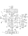
- 駆動源としてエンジンと電気モータとを備え、前記エンジン及び前記電気モータからの機械的動力を変速して駆動輪に係合する車両推進軸に伝達可能な駆動装置と、前記駆動装置による車両の駆動を制御する制御手段と、を備えるハイブリッド車両の制御装置であって、
車速を検出する車速検出手段を備え、
前記駆動装置は、駆動力の伝達経路として、前記エンジンと前記駆動輪との間の第1伝達経路と、前記電気モータと前記駆動輪との間の第2伝達経路と、前記モータと前記エンジンとの間の第3伝達経路とを少なくとも有し、
駆動源として前記電気モータのみを用いた車両走行であるモータ単独走行中に前記エンジンを始動するモードとして、
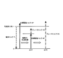
前記車速検出手段で検出した車速が所定車速以上の場合、前記第1伝達経路を介して前記駆動輪からの駆動力を前記エンジンに伝達して該エンジン始動する押し掛け始動モードと、
前記車速検出手段で検出した車速が停車状態を含む他の所定車速以下の場合、前記第3伝達経路を介して前記モータの駆動力で前記エンジンを始動するモータ始動モードとが可能であり、
前記制御手段は、
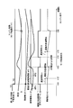
前記電気モータのみを駆動源とする走行中に、前記エンジンの始動指令が発生したときに、前記車速検出手段で検出した車速が前記押し掛け始動モードと前記モータ始動モードのいずれかを実施可能な車速領域以外の車速である場合、
前記電気モータから車両の前記駆動輪に伝達される駆動力を低減させる駆動力低減制御を実施する
ことを特徴とするハイブリッド車両の制御装置。 A drive device comprising an engine and an electric motor as drive sources, capable of shifting mechanical power from the engine and the electric motor to be transmitted to a vehicle propulsion shaft engaged with a drive wheel, and driving of the vehicle by the drive device A control device for controlling the vehicle, and a hybrid vehicle control device comprising:
Vehicle speed detection means for detecting the vehicle speed,
The drive device includes a first transmission path between the engine and the driving wheel, a second transmission path between the electric motor and the driving wheel, a motor and the engine as a driving force transmission path. And at least a third transmission path between
As a mode for starting the engine during motor traveling alone, which is vehicle traveling using only the electric motor as a drive source,
When the vehicle speed detected by the vehicle speed detection means is equal to or higher than a predetermined vehicle speed, a push start mode for transmitting the driving force from the driving wheels to the engine via the first transmission path and starting the engine;
When the vehicle speed detected by the vehicle speed detection means is equal to or lower than another predetermined vehicle speed including a stopped state, a motor start mode in which the engine is started by the driving force of the motor via the third transmission path is possible.
The control means includes
A vehicle speed at which the vehicle speed detected by the vehicle speed detection means can implement either the pushing start mode or the motor start mode when a start command for the engine is generated during traveling using only the electric motor as a drive source. If the vehicle speed is outside the range,
A hybrid vehicle control device that performs drive force reduction control for reducing drive force transmitted from the electric motor to the drive wheels of the vehicle. - 駆動源としてエンジンと電気モータとを備え、前記エンジン及び前記電気モータからの機械的動力を変速して駆動輪に係合する車両推進軸に伝達可能な駆動装置と、前記駆動装置による車両の駆動を制御する制御手段と、を備えるハイブリッド車両の制御装置であって、
前記エンジンの出力軸及び前記電気モータからの機械的動力を第1入力軸で受け、複数の変速段のうちいずれか1つにより変速して、車両推進軸に伝達可能な第1変速機構と、
前記内燃機関の出力軸からの機械的動力を第2入力軸で受け、複数の変速段のうちいずれか1つにより変速して、車両推進軸に伝達可能な第2変速機構と、
前記エンジンの出力軸と前記第1入力軸とを係合可能な第1クラッチと、
前記エンジンの出力軸と前記第2入力軸とを係合可能な第2クラッチと、
車速を検出する車速検出手段と、を備え、
駆動源として前記電気モータのみを用いた車両走行であるモータ単独走行中に前記エンジンを始動するモードとして、
前記第1変速機構を介して前記電気モータからの駆動力を前記駆動輪側に伝達して前記車両を走行させている状態で、前記車速検出手段で検出した車速が所定車速以上の場合、前記第2変速機構の変速段のいずれかを設定すると共に前記第2クラッチを係合状態とすることで、前記駆動輪からの駆動力を前記第2変速機構及び前記第2クラッチを介して前記エンジンに伝達して該エンジン始動する押し掛け始動モードと、
前記車速検出手段で検出した車速が停車状態を含む所定車速以下の場合、前記第1変速機構の変速段をいずれもニュートラルにして前記第1クラッチを係合することで、前記電気モータの駆動力で前記エンジンを始動するモータ始動モードとが可能であり、
前記制御手段は、
前記電気モータのみを駆動源とする走行中に、前記エンジンの始動指令が発生したときに、前記車速検出手段で検出した車速が前記押し掛け始動モードと前記モータ始動モードのいずれかを実施可能な車速領域以外の車速である場合、
前記電気モータから車両の前記駆動輪に伝達される駆動力を低減させる駆動力低減制御を実施する
ことを特徴とするハイブリッド車両の制御装置。 A drive device comprising an engine and an electric motor as drive sources, capable of shifting mechanical power from the engine and the electric motor to be transmitted to a vehicle propulsion shaft engaged with a drive wheel, and driving of the vehicle by the drive device A control device for controlling the vehicle, and a hybrid vehicle control device comprising:
A first speed change mechanism capable of receiving mechanical power from the output shaft of the engine and the electric motor by a first input shaft, shifting the speed by any one of a plurality of shift stages, and transmitting it to the vehicle propulsion shaft;
A second speed change mechanism capable of receiving mechanical power from an output shaft of the internal combustion engine by a second input shaft, shifting the speed by any one of a plurality of shift stages, and transmitting the speed to the vehicle propulsion shaft;
A first clutch capable of engaging the output shaft of the engine and the first input shaft;
A second clutch capable of engaging the output shaft of the engine and the second input shaft;
Vehicle speed detection means for detecting the vehicle speed,
As a mode for starting the engine during motor traveling alone, which is vehicle traveling using only the electric motor as a drive source,
When the vehicle speed detected by the vehicle speed detection means is equal to or higher than a predetermined vehicle speed in a state where the driving force from the electric motor is transmitted to the driving wheel side via the first transmission mechanism and the vehicle is running, By setting one of the shift stages of the second transmission mechanism and bringing the second clutch into an engaged state, the driving force from the driving wheel is transmitted to the engine via the second transmission mechanism and the second clutch. A push start mode for transmitting to the engine and starting the engine;
When the vehicle speed detected by the vehicle speed detecting means is equal to or lower than a predetermined vehicle speed including a stop state, the driving force of the electric motor is obtained by engaging the first clutch with all the gear positions of the first transmission mechanism being in neutral. And a motor start mode for starting the engine is possible,
The control means includes
A vehicle speed at which the vehicle speed detected by the vehicle speed detection means can implement either the pushing start mode or the motor start mode when a start command for the engine is generated during traveling using only the electric motor as a drive source. If the vehicle speed is outside the range,
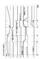
A hybrid vehicle control device that performs drive force reduction control for reducing drive force transmitted from the electric motor to the drive wheels of the vehicle. - アクセル開度を検出するアクセル開度検出手段を備え、
前記制御手段は、前記駆動力低減制御の実施中に、前記アクセル開度検出手段で検出したアクセル開度が所定以上になった場合、前記駆動力低減制御の実施を解除する
ことを特徴とする請求項1又は2に記載のハイブリッド車両の制御装置。 Accelerator opening detection means for detecting the accelerator opening,
The control means cancels the execution of the driving force reduction control when the accelerator opening detected by the accelerator opening detection means becomes a predetermined value or more during the driving force reduction control. The control apparatus of the hybrid vehicle of Claim 1 or 2. - 前記制御手段は、
前記駆動力低減制御の実施を解除した場合、前記アクセル開度検出手段で検出したアクセル開度が前記所定値未満になったら、再度、前記駆動力低減制御を実施する
ことを特徴とする請求項3に記載のハイブリッド車両の制御装置。 The control means includes
The driving force reduction control is performed again when the accelerator opening detected by the accelerator opening detection means becomes less than the predetermined value when the driving force reduction control is canceled. 3. A control device for a hybrid vehicle according to 3. - 車両に制動力を付与する制動力付与手段を備え、
前記制御手段は、
前記駆動力低減制御の実施中に、前記車速検出手段で検出した車速が前記他の所定車速以下になった場合、前記制動力付与手段による前記車両の制動を行うと共に、前記モータ始動モードによるエンジン始動を行う
ことを特徴とする請求項1又は2に記載のハイブリッド車両の制御装置。 A braking force applying means for applying a braking force to the vehicle;
The control means includes
When the vehicle speed detected by the vehicle speed detection means becomes equal to or lower than the other predetermined vehicle speed during the driving force reduction control, the vehicle is braked by the braking force applying means and the engine in the motor start mode is used. The hybrid vehicle control device according to claim 1, wherein the control is performed. - 前記駆動力低減制御の実施中に、前記車速検出手段で検出した車速が前記所定車速以上になった場合、前記押し掛け始動モードによるエンジン始動を行う
ことを特徴とする請求項1又は2に記載のハイブリッド車両の制御装置。 3. The engine is started in the pushing start mode when the vehicle speed detected by the vehicle speed detection unit becomes equal to or higher than the predetermined vehicle speed during the driving force reduction control. Control device for hybrid vehicle. - 車両の走行している路面の勾配を検出する勾配検出手段を備え、
前記制御手段は、
前記勾配検出手段で検出した路面の勾配に応じて、前記押し掛け始動モードによるエンジン始動を許可する車速の領域を拡大する
ことを特徴とする請求項1又は2に記載のハイブリッド車両の制御装置。 Comprising a gradient detecting means for detecting the gradient of the road surface on which the vehicle is running;
The control means includes
3. The hybrid vehicle control device according to claim 1, wherein an area of a vehicle speed at which engine start in the pushing start mode is permitted is expanded according to a road surface gradient detected by the gradient detection unit. - 車両の走行している路面の勾配を検出する勾配検出手段を備え、
前記制御手段は、
前記勾配検出手段で検出した路面の勾配が所定以上の場合に前記駆動力低減制御を実施する
ことを特徴とする請求項1又は2に記載のハイブリッド車両の制御装置。 Comprising a gradient detecting means for detecting the gradient of the road surface on which the vehicle is running;
The control means includes
3. The hybrid vehicle control device according to claim 1, wherein the driving force reduction control is performed when a road surface gradient detected by the gradient detection unit is greater than or equal to a predetermined value. 4. - 前記制御手段による前記駆動力低減制御の指令から実施までの間に所定の遅延時間を設ける
ことを特徴とする請求項1又は2に記載のハイブリッド車両の制御装置。 3. The hybrid vehicle control device according to claim 1, wherein a predetermined delay time is provided between the command and the execution of the driving force reduction control by the control means. 4. - 前記電気モータとの間で電力の授受が可能な蓄電器と、
前記蓄電器の残容量を検出する残容量検出手段と、を備え、
前記制御手段は、
前記残容量検出手段で検出した前記蓄電器の残容量に応じて前記押し掛け始動モードを実施可能な車速領域を持ち替える
ことを特徴とする請求項1又は2に記載のハイブリッド車両の制御装置。 A battery capable of transferring power to and from the electric motor;
A remaining capacity detecting means for detecting the remaining capacity of the battery,
The control means includes
3. The control apparatus for a hybrid vehicle according to claim 1, wherein a vehicle speed region in which the pushing start mode can be implemented is changed according to the remaining capacity of the battery detected by the remaining capacity detecting means. - 前記電気モータとの間で電力の授受が可能な蓄電器と、
前記蓄電器の残容量を検出する残容量検出手段と、を備え、
前記制御手段は、
前記残容量検出手段で検出した前記蓄電器の残容量が所定以下のときに前記エンジンの始動指令を行う
ことを特徴とする請求項1又は2に記載のハイブリッド車両の制御装置。 A battery capable of transferring power to and from the electric motor;
A remaining capacity detecting means for detecting the remaining capacity of the battery,
The control means includes
The hybrid vehicle control device according to claim 1 or 2, wherein the engine start command is issued when a remaining capacity of the battery detected by the remaining capacity detecting means is equal to or less than a predetermined value.
Priority Applications (6)
| Application Number | Priority Date | Filing Date | Title |
|---|---|---|---|
| JP2015513679A JP6096288B2 (en) | 2013-04-22 | 2014-04-11 | Control device for hybrid vehicle |
| KR1020157030456A KR101692663B1 (en) | 2013-04-22 | 2014-04-11 | Hybrid vehicle control device |
| EP14787878.9A EP2990285B1 (en) | 2013-04-22 | 2014-04-11 | Hybrid vehicle control device |
| CA2909980A CA2909980C (en) | 2013-04-22 | 2014-04-11 | Control device for hybrid vehicle |
| US14/784,188 US9827981B2 (en) | 2013-04-22 | 2014-04-11 | Control device for hybrid vehicle |
| CN201480021142.4A CN105121244B (en) | 2013-04-22 | 2014-04-11 | The control device of motor vehicle driven by mixed power |
Applications Claiming Priority (2)
| Application Number | Priority Date | Filing Date | Title |
|---|---|---|---|
| JP2013089430 | 2013-04-22 | ||
| JP2013-089430 | 2013-04-22 |
Publications (1)
| Publication Number | Publication Date |
|---|---|
| WO2014175080A1 true WO2014175080A1 (en) | 2014-10-30 |
Family
ID=51791660
Family Applications (1)
| Application Number | Title | Priority Date | Filing Date |
|---|---|---|---|
| PCT/JP2014/060505 WO2014175080A1 (en) | 2013-04-22 | 2014-04-11 | Hybrid vehicle control device |
Country Status (7)
| Country | Link |
|---|---|
| US (1) | US9827981B2 (en) |
| EP (1) | EP2990285B1 (en) |
| JP (1) | JP6096288B2 (en) |
| KR (1) | KR101692663B1 (en) |
| CN (1) | CN105121244B (en) |
| CA (1) | CA2909980C (en) |
| WO (1) | WO2014175080A1 (en) |
Cited By (4)
| Publication number | Priority date | Publication date | Assignee | Title |
|---|---|---|---|---|
| JPWO2014175080A1 (en) * | 2013-04-22 | 2017-02-23 | 本田技研工業株式会社 | Control device for hybrid vehicle |
| JP6188110B1 (en) * | 2017-01-04 | 2017-08-30 | 寛治 泉 | Automobile inertia traveling control system. |
| JP2017165300A (en) * | 2016-03-17 | 2017-09-21 | 本田技研工業株式会社 | Saddle-riding type vehicle |
| WO2019044275A1 (en) * | 2017-08-27 | 2019-03-07 | 泉寛治 | Inertia travel control system for automobiles |
Families Citing this family (23)
| Publication number | Priority date | Publication date | Assignee | Title |
|---|---|---|---|---|
| JP6136714B2 (en) * | 2013-07-30 | 2017-05-31 | トヨタ自動車株式会社 | Vehicle control device |
| US10315505B2 (en) * | 2015-06-11 | 2019-06-11 | Honda Motor Co., Ltd. | Internal-combustion engine starting device, vehicle, and internal-combustion engine starting method |
| KR101826550B1 (en) * | 2015-11-30 | 2018-02-07 | 현대자동차 주식회사 | Device for controlling shift of vehicle and method for controlling shift using the same |
| US9937919B2 (en) * | 2016-03-10 | 2018-04-10 | Ford Global Technologies, Llc | System and method for coupled and decoupled engine starting in a hybrid vehicle |
| KR101795299B1 (en) * | 2016-09-08 | 2017-12-01 | 현대자동차주식회사 | Method for Driving Performance Guarantee of Engine and Hybrid Electric Vehicle thereof |
| KR101916073B1 (en) * | 2016-10-21 | 2018-11-07 | 현대자동차 주식회사 | Power transmission system of hybrid electric vehicle |
| JP6550663B2 (en) * | 2016-11-04 | 2019-07-31 | 本田技研工業株式会社 | Vehicle control device, vehicle control method, and vehicle control program |
| KR102565346B1 (en) * | 2016-12-12 | 2023-08-16 | 현대자동차주식회사 | Shifting control method for hybrid vehicles |
| DE102017105407A1 (en) * | 2017-03-14 | 2018-09-20 | GETRAG B.V. & Co. KG | Method for operating a motor vehicle |
| DE102017111003A1 (en) * | 2017-05-19 | 2018-11-22 | Wabco Europe Bvba | Method for determining autonomous emergency braking, method for performing emergency braking, and control system for a vehicle dynamics system |
| JP2020152121A (en) * | 2017-07-18 | 2020-09-24 | ヤマハ発動機株式会社 | Vehicle |
| US10618512B2 (en) * | 2017-08-04 | 2020-04-14 | Toyota Motor Engineering & Manufacturing North America, Inc. | Expanding electric vehicle mode during downhill grade conditions |
| JP6596480B2 (en) * | 2017-11-29 | 2019-10-23 | 本田技研工業株式会社 | Control device for hybrid vehicle |
| JP6908130B2 (en) * | 2017-12-04 | 2021-07-28 | 三菱自動車工業株式会社 | Vehicle control device |
| JP6982543B2 (en) * | 2018-05-15 | 2021-12-17 | 本田技研工業株式会社 | Hybrid vehicle drive |
| JP7073923B2 (en) * | 2018-06-05 | 2022-05-24 | トヨタ自動車株式会社 | Hybrid vehicle |
| US11225244B2 (en) * | 2019-05-30 | 2022-01-18 | Ford Global Technologies, Llc | Hybrid vehicle engine start and shift control strategy |
| KR20210003350A (en) * | 2019-07-01 | 2021-01-12 | 현대자동차주식회사 | Method for Engine Restart Control of Vehicle |
| KR102135860B1 (en) * | 2019-07-02 | 2020-07-21 | 주식회사 브이씨텍 | Speed limiting method in ramp for electric power based vehicle |
| CN112026745B (en) * | 2020-09-01 | 2021-12-21 | 潍柴动力股份有限公司 | Hybrid electric vehicle driving mode adjusting method and device and hybrid electric vehicle |
| JP2022049811A (en) * | 2020-09-17 | 2022-03-30 | トヨタ自動車株式会社 | Hybrid vehicular control apparatus |
| JP2022154132A (en) * | 2021-03-30 | 2022-10-13 | 本田技研工業株式会社 | Control device for hybrid vehicle |
| CN113119751B (en) * | 2021-05-12 | 2022-11-01 | 湖南三一智能控制设备有限公司 | Vehicle slope starting method and device, vehicle, electronic equipment and storage medium |
Citations (11)
| Publication number | Priority date | Publication date | Assignee | Title |
|---|---|---|---|---|
| JP2001107763A (en) * | 1999-10-08 | 2001-04-17 | Toyota Motor Corp | Control device for vehicle provided with plurality of prime movers |
| JP2006009751A (en) * | 2004-06-29 | 2006-01-12 | Nissan Motor Co Ltd | Method for starting engine of vehicle with hybrid transmission |
| JP4225317B2 (en) | 2005-12-28 | 2009-02-18 | トヨタ自動車株式会社 | Hybrid vehicle |
| JP2009035188A (en) | 2007-08-03 | 2009-02-19 | Nissan Motor Co Ltd | Controller for hybrid vehicle |
| JP4285571B2 (en) | 2007-09-27 | 2009-06-24 | トヨタ自動車株式会社 | Vehicle drive device |
| JP4297116B2 (en) | 2006-01-24 | 2009-07-15 | 三菱ふそうトラック・バス株式会社 | Hybrid vehicle start control device and hybrid vehicle with start control device |
| JP2009166567A (en) * | 2008-01-11 | 2009-07-30 | Toyota Motor Corp | Hybrid vehicle |
| JP2010089537A (en) * | 2008-10-03 | 2010-04-22 | Toyota Motor Corp | Hybrid vehicle |
| JP2010184613A (en) * | 2009-02-12 | 2010-08-26 | Toyota Motor Corp | Hybrid vehicle |
| JP2011213181A (en) * | 2010-03-31 | 2011-10-27 | Honda Motor Co Ltd | Power controller for hybrid vehicle |
| JP2013043479A (en) * | 2011-08-22 | 2013-03-04 | Honda Motor Co Ltd | Hybrid vehicle and control method thereof |
Family Cites Families (7)
| Publication number | Priority date | Publication date | Assignee | Title |
|---|---|---|---|---|
| JP4725419B2 (en) * | 2006-06-01 | 2011-07-13 | 日産自動車株式会社 | Driving force control device for electric vehicle |
| JP5070004B2 (en) | 2007-10-31 | 2012-11-07 | 日立オートモティブシステムズ株式会社 | Control device for hybrid vehicle |
| DE102007055828A1 (en) * | 2007-12-17 | 2009-06-18 | Zf Friedrichshafen Ag | Method and device for operating a hybrid vehicle |
| RU2534146C2 (en) * | 2010-07-12 | 2014-11-27 | Хонда Мотор Ко., Лтд. | Controlling unit and method for hybrid vehicle control |
| CA2909980C (en) * | 2013-04-22 | 2017-11-14 | Honda Motor Co., Ltd. | Control device for hybrid vehicle |
| US9086045B2 (en) * | 2013-10-18 | 2015-07-21 | Ford Global Technologies, Llc | Hybrid vehicle engine starts |
| US9327721B2 (en) * | 2014-07-15 | 2016-05-03 | Ford Global Technologies, Llc | Methods and systems for starting an engine while a vehicle is creeping |
-
2014
- 2014-04-11 CA CA2909980A patent/CA2909980C/en not_active Expired - Fee Related
- 2014-04-11 WO PCT/JP2014/060505 patent/WO2014175080A1/en active Application Filing
- 2014-04-11 KR KR1020157030456A patent/KR101692663B1/en active IP Right Grant
- 2014-04-11 JP JP2015513679A patent/JP6096288B2/en not_active Expired - Fee Related
- 2014-04-11 US US14/784,188 patent/US9827981B2/en active Active
- 2014-04-11 EP EP14787878.9A patent/EP2990285B1/en not_active Not-in-force
- 2014-04-11 CN CN201480021142.4A patent/CN105121244B/en active Active
Patent Citations (11)
| Publication number | Priority date | Publication date | Assignee | Title |
|---|---|---|---|---|
| JP2001107763A (en) * | 1999-10-08 | 2001-04-17 | Toyota Motor Corp | Control device for vehicle provided with plurality of prime movers |
| JP2006009751A (en) * | 2004-06-29 | 2006-01-12 | Nissan Motor Co Ltd | Method for starting engine of vehicle with hybrid transmission |
| JP4225317B2 (en) | 2005-12-28 | 2009-02-18 | トヨタ自動車株式会社 | Hybrid vehicle |
| JP4297116B2 (en) | 2006-01-24 | 2009-07-15 | 三菱ふそうトラック・バス株式会社 | Hybrid vehicle start control device and hybrid vehicle with start control device |
| JP2009035188A (en) | 2007-08-03 | 2009-02-19 | Nissan Motor Co Ltd | Controller for hybrid vehicle |
| JP4285571B2 (en) | 2007-09-27 | 2009-06-24 | トヨタ自動車株式会社 | Vehicle drive device |
| JP2009166567A (en) * | 2008-01-11 | 2009-07-30 | Toyota Motor Corp | Hybrid vehicle |
| JP2010089537A (en) * | 2008-10-03 | 2010-04-22 | Toyota Motor Corp | Hybrid vehicle |
| JP2010184613A (en) * | 2009-02-12 | 2010-08-26 | Toyota Motor Corp | Hybrid vehicle |
| JP2011213181A (en) * | 2010-03-31 | 2011-10-27 | Honda Motor Co Ltd | Power controller for hybrid vehicle |
| JP2013043479A (en) * | 2011-08-22 | 2013-03-04 | Honda Motor Co Ltd | Hybrid vehicle and control method thereof |
Non-Patent Citations (1)
| Title |
|---|
| See also references of EP2990285A4 |
Cited By (7)
| Publication number | Priority date | Publication date | Assignee | Title |
|---|---|---|---|---|
| JPWO2014175080A1 (en) * | 2013-04-22 | 2017-02-23 | 本田技研工業株式会社 | Control device for hybrid vehicle |
| US9827981B2 (en) | 2013-04-22 | 2017-11-28 | Honda Motor Co., Ltd. | Control device for hybrid vehicle |
| JP2017165300A (en) * | 2016-03-17 | 2017-09-21 | 本田技研工業株式会社 | Saddle-riding type vehicle |
| JP6188110B1 (en) * | 2017-01-04 | 2017-08-30 | 寛治 泉 | Automobile inertia traveling control system. |
| JP2018108781A (en) * | 2017-01-04 | 2018-07-12 | 寛治 泉 | Automotive inertial travel control system |
| WO2019044275A1 (en) * | 2017-08-27 | 2019-03-07 | 泉寛治 | Inertia travel control system for automobiles |
| JPWO2019044275A1 (en) * | 2017-08-27 | 2019-11-07 | 寛治 泉 | Automobile inertia traveling control system. |
Also Published As
| Publication number | Publication date |
|---|---|
| CN105121244B (en) | 2017-09-22 |
| EP2990285A1 (en) | 2016-03-02 |
| CN105121244A (en) | 2015-12-02 |
| JP6096288B2 (en) | 2017-03-15 |
| JPWO2014175080A1 (en) | 2017-02-23 |
| CA2909980A1 (en) | 2014-10-30 |
| EP2990285A4 (en) | 2017-03-08 |
| EP2990285B1 (en) | 2018-07-18 |
| KR20150134395A (en) | 2015-12-01 |
| CA2909980C (en) | 2017-11-14 |
| US9827981B2 (en) | 2017-11-28 |
| US20160052511A1 (en) | 2016-02-25 |
| KR101692663B1 (en) | 2017-01-17 |
Similar Documents
| Publication | Publication Date | Title |
|---|---|---|
| JP6096288B2 (en) | Control device for hybrid vehicle | |
| JP5942412B2 (en) | Vehicle drive device | |
| JP5899018B2 (en) | Control device for hybrid vehicle | |
| CN107813695B (en) | Control device for hybrid vehicle | |
| US20120149514A1 (en) | Motor-assisted transmission | |
| JP5899047B2 (en) | Control device and control method for hybrid vehicle | |
| CN107813811B (en) | Control device for hybrid vehicle | |
| JP2011126318A (en) | Start control device for hybrid electric vehicle | |
| JP2012224132A (en) | Shift control system of hybrid vehicle | |
| JP5906142B2 (en) | Control device and control method for hybrid vehicle | |
| JP6069121B2 (en) | Vehicle drive control device | |
| JP5989303B2 (en) | Hybrid vehicle | |
| WO2014162760A1 (en) | Vehicle controller | |
| JP5929738B2 (en) | Control device for hybrid vehicle | |
| JP5855603B2 (en) | Control device for hybrid vehicle | |
| JP5947059B2 (en) | Control device for hybrid vehicle | |
| JP5932460B2 (en) | Control device for hybrid vehicle | |
| JP6310904B2 (en) | Control device for hybrid vehicle | |
| JP2014054952A (en) | Hybrid vehicle control device | |
| JP2013035404A (en) | Hybrid vehicle and method for controlling the same | |
| JP6002541B2 (en) | Control device and control method for hybrid vehicle | |
| JP5575520B2 (en) | Power control device for hybrid vehicle | |
| WO2022118896A1 (en) | Drive device for vehicle | |
| JP2022087708A (en) | Vehicle drive device | |
| JP2022115428A (en) | automatic transmission |
Legal Events
| Date | Code | Title | Description |
|---|---|---|---|
| WWE | Wipo information: entry into national phase |
Ref document number: 201480021142.4 Country of ref document: CN |
|
| 121 | Ep: the epo has been informed by wipo that ep was designated in this application |
Ref document number: 14787878 Country of ref document: EP Kind code of ref document: A1 |
|
| ENP | Entry into the national phase |
Ref document number: 2015513679 Country of ref document: JP Kind code of ref document: A |
|
| WWE | Wipo information: entry into national phase |
Ref document number: 14784188 Country of ref document: US |
|
| WWE | Wipo information: entry into national phase |
Ref document number: 2014787878 Country of ref document: EP |
|
| ENP | Entry into the national phase |
Ref document number: 2909980 Country of ref document: CA |
|
| ENP | Entry into the national phase |
Ref document number: 20157030456 Country of ref document: KR Kind code of ref document: A |
|
| NENP | Non-entry into the national phase |
Ref country code: DE |