EP3067553B1 - Structure de sécurité pour effectuer des opérations de service dans une éolienne et procédé pour son installation - Google Patents
Structure de sécurité pour effectuer des opérations de service dans une éolienne et procédé pour son installation Download PDFInfo
- Publication number
- EP3067553B1 EP3067553B1 EP15382115.2A EP15382115A EP3067553B1 EP 3067553 B1 EP3067553 B1 EP 3067553B1 EP 15382115 A EP15382115 A EP 15382115A EP 3067553 B1 EP3067553 B1 EP 3067553B1
- Authority
- EP
- European Patent Office
- Prior art keywords
- wind turbine
- support member
- safety
- safety bars
- bars
- Prior art date
- Legal status (The legal status is an assumption and is not a legal conclusion. Google has not performed a legal analysis and makes no representation as to the accuracy of the status listed.)
- Active
Links
Images
Classifications
-
- F—MECHANICAL ENGINEERING; LIGHTING; HEATING; WEAPONS; BLASTING
- F03—MACHINES OR ENGINES FOR LIQUIDS; WIND, SPRING, OR WEIGHT MOTORS; PRODUCING MECHANICAL POWER OR A REACTIVE PROPULSIVE THRUST, NOT OTHERWISE PROVIDED FOR
- F03D—WIND MOTORS
- F03D13/00—Assembly, mounting or commissioning of wind motors; Arrangements specially adapted for transporting wind motor components
- F03D13/10—Assembly of wind motors; Arrangements for erecting wind motors
-
- E—FIXED CONSTRUCTIONS
- E04—BUILDING
- E04G—SCAFFOLDING; FORMS; SHUTTERING; BUILDING IMPLEMENTS OR AIDS, OR THEIR USE; HANDLING BUILDING MATERIALS ON THE SITE; REPAIRING, BREAKING-UP OR OTHER WORK ON EXISTING BUILDINGS
- E04G21/00—Preparing, conveying, or working-up building materials or building elements in situ; Other devices or measures for constructional work
- E04G21/32—Safety or protective measures for persons during the construction of buildings
-
- F—MECHANICAL ENGINEERING; LIGHTING; HEATING; WEAPONS; BLASTING
- F03—MACHINES OR ENGINES FOR LIQUIDS; WIND, SPRING, OR WEIGHT MOTORS; PRODUCING MECHANICAL POWER OR A REACTIVE PROPULSIVE THRUST, NOT OTHERWISE PROVIDED FOR
- F03D—WIND MOTORS
- F03D80/00—Details, components or accessories not provided for in groups F03D1/00 - F03D17/00
- F03D80/50—Maintenance or repair
-
- Y—GENERAL TAGGING OF NEW TECHNOLOGICAL DEVELOPMENTS; GENERAL TAGGING OF CROSS-SECTIONAL TECHNOLOGIES SPANNING OVER SEVERAL SECTIONS OF THE IPC; TECHNICAL SUBJECTS COVERED BY FORMER USPC CROSS-REFERENCE ART COLLECTIONS [XRACs] AND DIGESTS
- Y02—TECHNOLOGIES OR APPLICATIONS FOR MITIGATION OR ADAPTATION AGAINST CLIMATE CHANGE
- Y02E—REDUCTION OF GREENHOUSE GAS [GHG] EMISSIONS, RELATED TO ENERGY GENERATION, TRANSMISSION OR DISTRIBUTION
- Y02E10/00—Energy generation through renewable energy sources
- Y02E10/70—Wind energy
- Y02E10/72—Wind turbines with rotation axis in wind direction
Definitions
- Safety structures for performing servicing operations outside wind turbine blade pitch bearings are disclosed herein.
- the present disclosure also refers to a method for installing said structures for performing servicing operations outside wind turbine blade pitch bearings.
- servicing operations comprise operations intended to ensure operational safety such as, for example, monitoring, inspection, repair and maintenance operations.
- Maintenance operations may comprise, for example, regularly retightening the bolts in the rotor for joining the pitch bearing to the hub in wind turbines.
- Inspection operations may comprise, for example, periodically inspecting pitch lubrication equipment outside wind turbines. All of such operations involve operators working in dangerous and critical areas at great heights outside the wind turbines.
- a safety line is usually used to protect the operator(s) working outside wind turbines in addition to the use of other safety devices such as harnesses. This is regulated under guidelines in the wind sector such as the Environmental Health and safety (EHS) guidelines for hazard prevention in wind turbines.
- EHS Environmental Health and safety
- EP2484893 discloses the use of a service platform attached to a wind turbine hub.
- the service platform comprises a flange extending outwards from the blade root perpendicular to the longitudinal blade axis, acting as a walkway including guardrails extending along the circumference of the platform.
- WO200531159 discloses an equipment to be connected on a wind turbine hub for performing service operations through connecting pieces. It comprises a crane, a gangway with guard rails, a ladder leading from the nacelle to the gangway and a curb mounted on the hub suspended from the crane. The crane is secured to the first connecting piece, and the gangway is secured to the crane and to the second connecting piece.
- EP2505834 refers to a platform with detachable elements intended to be installed in a ladder inside a wind turbine tower. It comprises a horizontal surface, tensionable elements that support it, anchors secured by pins to the ladder and a railing anchored to the platform and reinforced by intermediate bars and a plate.
- EP2466129 discloses a platform formed integral with a wind turbine nacelle such that the roof of the nacelle is at the same time the floor of the platform.
- the platform comprises railings attached to the floor thereof and to the roof of the nacelle defining the borders of the platform.
- a safety structure is disclosed herein for performing servicing operations outside a wind turbine blade pitch bearing.
- Servicing operations may include monitoring, inspection, repair and maintenance operations and many other operations to be performed outside a wind turbine blade pitch bearing.
- the present safety structure is intended to be installed outside a wind blade pitch bearing.
- the present safety structure comprises a number of temporarily deployable safety bars.
- the safety bars are adapted to be installed to the wind turbine such that they can be easily removed once the servicing operations have been completed.
- the temporarily deployable safety bars can be attached to a support member that is associated with the wind turbine.
- the support member may be provided in the wind turbine with the safety bars permanently attached thereto.
- the safety bars are adapted to be removably attached to the support member.
- one end of the temporarily deployable safety bars for example a lower end, may be adapted to be removably coupled to the support member.
- the temporarily deployable safety bars might be telescopic to adapt the height of the safety structure according to the requirements. This may allow the safety structure to be properly stored.
- Bar locking means may be also provided. Such bar locking means serve the purpose of locking the temporarily deployable safety bars to the support member. As described above, the locking means may be removable such that the bars are removably coupled to the support member.
- the bar locking means may include magnetic parts, such as permanent magnets. Said magnetic parts are capable of generating a magnetic field suitable for attaching the temporarily deployable safety bars to the support member that is associated with the wind turbine.
- At least the safety bars comprise at least one inflatable portion. In some cases, it may be preferred that most of the elements of the safety structure comprise inflatable portions. The inflatable portions are suitable to protect operators against shocks during servicing operations in the wind turbine.
- the present safety structure may include at least one bar coupling member for coupling the temporarily deployable safety bars to each other.
- the bar coupling member is capable of coupling the temporarily deployable safety bars to each other defining a fence structure.
- Such bar coupling member may comprise, for example, at least one coupling rope, at least one wire, at least one coupling mesh, or the like. It may be preferred that the bar coupling member is retractable. This facilitates and speeds up removal and storage of the safety structure parts.
- the support member that is associated with the wind turbine may be adapted to define a base surface to facilitate the passage of at least one operator. This may be advantageous when the support member is not properly adapted for the passage of at least one operator when performing servicing operations in the wind turbine.
- the support member may be permanently attached to at least one of a wind turbine hub, a wind turbine blade, a wind turbine root section and a pitch bearing.
- the safety structure can be thus easily installed on a large number of wind turbine parts.
- the temporarily deployable safety bars can be attached to the support member such that they are distributed on the support member covering an angle of at least 240° around the wind turbine part. This allows an access for the operator to be properly defined to reach the wind turbine part on which the servicing operations are to be performed.
- the main advantage of the above described safety structure is it can be easily installed for performing monitoring, repair, servicing, inspecting, and maintenance operations and the like in a wind turbine while safely protecting the operator and according to current safety guidelines in wind sector.
- the safety structure can be installed quickly and can be removed easily once said operation has been completed.
- a method for installing the above safety structure is also provided by means of which monitoring, repair, servicing, inspecting, and maintenance operations can be safely performed outside a wind turbine blade pitch bearing.
- the method comprises attaching a number of temporarily deployable safety bars to a support member that is arranged at least partially surrounding the wind turbine blade bearing.
- the deployable safety bars could be already attached to each other or they could be provided as separate parts to be removably attached to the support member. If the safety bars are provided as separate parts, the safety bars should be coupled with each other. This may be carried out, for example, through one or a number of bar coupling members for defining a fence like structure.
- the already mounted safety structure is then ready to use for performing servicing operations on the wind turbine.
- the safety structure can be easily removed simply by detaching safety bars from the support member and decoupling the bar coupling members to disassemble the fence structure, if required.
- the safety bars can be conveniently stored in any suitable place.
- the present safety structure and method allow risky situations for operators hanging at great heights such as 1.5 m or more from a harness to be avoided. The likelihood of accidents and injuries and thus costs are advantageously reduced. No extra structures or tools are required.
- the safety structure that has been described above can be applied to many parts of a wind turbine.
- This structure is generally intended to be installed preferably on a horizontal plane, at least partially covering a perimeter, as stated above, to provide access to the operator to a wind turbine part to be inspected or where inspecting, monitoring, repair, servicing and maintenance operations, and other operations, are required to be performed in wind turbines.
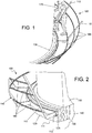
- a safety structure 100 for performing monitoring, inspection, repair, servicing and maintenance operations and the like in a wind turbine blade pitch bearing 130 is shown.
- the present safety structure 100 can be of course used for performing said operations and many more in other wind turbine parts.
- the safety structure 100 shown in figure 1 and 2 comprises a number of temporarily deployable safety metallic bars 110.
- the safety bars 110 are shown in the figures attached to a support member 120 with the safety bars 110 arranged surrounding the wind turbine blade pitch bearing 130.
- the support member 120 in the example shown is attached to the wind turbine pitch bearing 130.
- the pitch bearing 130 is thus attached both to the wind turbine hub 140 and to the blade root 150.
- the support member 120 is disclosed herein as being attached to the wind turbine pitch bearing 130, the support member 120 could be made integral with the turbine pitch bearing 130 or with any other suitable part of the wind turbine as required.
- the support member 120 whether it is a separate part or it is embedded in a wind turbine part, can be attached only to the pitch bearing 130 or directly to the hub 140 as required.
- the temporarily deployable safety bars 110 in the example shown have a substantially horizontal bottom portion 111.
- the bottom portion 111 of the safety bars 110 extends into a substantially outwardly inclined portion 112.
- the bottom portion 111 together with the support member 120, form a base surface to facilitate the passage of the operator or operators 170, as shown in figure 1 of the drawings.
- the bottom portion 111, the outwardly inclined portion 112, or both portions 111, 112 of the safety bars 110 may be telescopic.
- a lower end 113 of the bottom portion 111 is adapted to be removably coupled to the support member 120.
- the lower end 113 of the bottom portion 111 has a substantially U shaped profile to slidingly receive a complimentarily shaped guide portion 125 in the support member 120.
- the safety bars 110 are thus allowed to run along the guide portion 125 of the support member 120.
- the safety bars 110 can be thus suitably removably locked to the support member 120 through any appropriate bar locking means such as magnetic means.
- Bar coupling members 160 are also provided for coupling the safety bars 110 to each other.
- the bar coupling members 160 comprise a number of substantially parallel ropes or wires extending between the safety bars 110.
- a fence structure is defined.
- the ropes 160 may be retractable for facilitating removal and storage of the safety structure 100.
- the fence structure defined by the safety bars 110 and the ropes 160 might not completely cover the blade root 150 but an angle of at least 240° for example around the blade root 150. This has the purpose of allowing access for the operator 170 to a wind turbine part when required.
- a number of temporarily deployable safety bars 110 are attached separately to the support member 120 surrounding the wind turbine blade pitch bearing 130. Then, the safety bars 110 are coupled to each other through the ropes 160 forming a fence structure.
- the safety structure 100 With the safety bars 110 coupled to each other through the ropes 160, the safety structure 100 is ready to be used for performing servicing operations on the wind turbine. Once the servicing operations have been completed, the safety structure 100 can be disassembled by removing the ropes 160 and detaching the bars 110 from the support member 120. The safety bars 110 together with the ropes 160 can be stored in any suitable place inside the wind turbine or in a suitable place external thereto.
- the safety structure 100 is shown in the example drawings attached to the pitch bearing 130 or the hub 140, the safety structure 100 might be fixed to a ring extender, for example.
- an extra floor could be provided fixed to the hub 140 if required.
- the safety bars 110 could be thus removably attached to said floor through reinforced holes formed therein.
Claims (14)
- Une structure de sécurité (100) pour effectuer des opérations d'entretien hors d'un palier de régulation de pas de pale d'éolienne (130), caractérisée en ce que la structure de sécurité (100) comprend un certain nombre de barres de sécurité temporairement déployables (110) et un élément de support (120), dans laquelle les barres de sécurité (110) peuvent être attachées à l'élément de support (120), les barres de sécurité (110) étant disposées au moins en partie entourant le palier de régulation de pas de pale d'éolienne (130) et dans laquelle l'élément de support (120) est ou bien formé de façon intégrale avec ou bien attaché de façon permanente à l'un parmi un moyeu d'éolienne, une pale d'éolienne, une section de racine de pale d'éolienne, et un palier de régulation de pas (130).
- La structure (100) selon la revendication 1, dans laquelle les barres de sécurité temporairement déployables (110) sont distribuées sur l'élément de support (120) couvrant un angle d'au moins 240° autour du palier de régulation de pas de pale d'éolienne (130).
- La structure (100) selon la revendication 1 ou 2, dans laquelle les barres de sécurité temporairement déployables (110) ont une extrémité inférieure (113) adaptée pour être couplée de façon amovible à l'élément de support (120).
- La structure (100) selon l'une quelconque des revendications précédentes, dans laquelle elle inclut en outre un moyen de fixation des barres pour fixer les barres de sécurité temporairement déployables (110) sur l'élément de support (120).
- La structure (100) selon la revendication 4, dans laquelle le moyen de fixation des barres inclut des parties magnétiques capables de générer un champ magnétique pour attacher les barres de sécurité temporairement déployables (110) à l'élément de support (120).
- La structure (100) selon l'une quelconque des revendications précédentes, dans laquelle au moins lesdites barres de sécurité (110) comprennent au moins une partie gonflable.
- La structure (100) selon l'une quelconque des revendications précédentes, dans laquelle elle inclut en outre au moins un élément de couplage de barres (160) pour coupler les barres de sécurité temporairement déployables (110) l'une à l'autre en définissant une structure de type clôture.
- La structure (100) selon la revendication 7, dans laquelle l'élément de couplage de barres (160) comprend une corde ou un câble de couplage.
- La structure (100) selon la revendication 7 ou 8, dans laquelle l'élément de couplage de barres (160) comprend un treillis de couplage.
- La structure (100) selon l'une quelconque des revendications 7-9, dans laquelle l'élément de couplage de barres (160) est rétractable.
- La structure (100) selon l'une quelconque des revendications précédentes, dans laquelle l'élément de support (120) définit une surface de base pour faciliter le passage d'au moins un opérateur (170).
- La structure (100) selon l'une quelconque des revendications précédentes, dans laquelle les barres de sécurité temporairement déployables (110) sont télescopiques.
- Un procédé pour installer une structure de sécurité (100) pour effectuer des opérations d'entretien hors d'un palier de régulation de pas de pale d'éolienne (130), le procédé comprenant attacher un certain nombre de barres de sécurité temporairement déployables (110) à un élément de support (120) qui est disposé au moins en partie entourant le palier de régulation de pas de pale d'éolienne (130) et où l'élément de support (120) est ou bien formé de façon intégrale avec ou bien attaché de façon permanente à l'un parmi un moyeu d'éolienne, une pale d'éolienne, une section de racine de pale d'éolienne, et un palier de régulation de pas (130).
- Le procédé selon la revendication 13, comprenant en outre coupler les barres de sécurité temporairement déployables (110) les unes aux autres moyennent au moins un élément de couplage de barres (160), définissant ainsi une structure de type clôture.
Priority Applications (4)
| Application Number | Priority Date | Filing Date | Title |
|---|---|---|---|
| EP15382115.2A EP3067553B1 (fr) | 2015-03-13 | 2015-03-13 | Structure de sécurité pour effectuer des opérations de service dans une éolienne et procédé pour son installation |
| ES15382115T ES2751757T3 (es) | 2015-03-13 | 2015-03-13 | Estructura de seguridad para realizar operaciones de mantenimiento en un aerogenerador y procedimiento para su instalación |
| DK15382115.2T DK3067553T3 (da) | 2015-03-13 | 2015-03-13 | Sikkerhedsstruktur til udførelse af vedligeholdelsesarbejde på en vindmølle og fremgangsmåde til installering deraf |
| US15/066,998 US9869294B2 (en) | 2015-03-13 | 2016-03-10 | Safety structure for performing servicing operations in a wind turbine and method for its installation |
Applications Claiming Priority (1)
| Application Number | Priority Date | Filing Date | Title |
|---|---|---|---|
| EP15382115.2A EP3067553B1 (fr) | 2015-03-13 | 2015-03-13 | Structure de sécurité pour effectuer des opérations de service dans une éolienne et procédé pour son installation |
Publications (2)
| Publication Number | Publication Date |
|---|---|
| EP3067553A1 EP3067553A1 (fr) | 2016-09-14 |
| EP3067553B1 true EP3067553B1 (fr) | 2019-07-17 |
Family
ID=52697344
Family Applications (1)
| Application Number | Title | Priority Date | Filing Date |
|---|---|---|---|
| EP15382115.2A Active EP3067553B1 (fr) | 2015-03-13 | 2015-03-13 | Structure de sécurité pour effectuer des opérations de service dans une éolienne et procédé pour son installation |
Country Status (4)
| Country | Link |
|---|---|
| US (1) | US9869294B2 (fr) |
| EP (1) | EP3067553B1 (fr) |
| DK (1) | DK3067553T3 (fr) |
| ES (1) | ES2751757T3 (fr) |
Families Citing this family (2)
| Publication number | Priority date | Publication date | Assignee | Title |
|---|---|---|---|---|
| FR3067017B1 (fr) * | 2017-06-02 | 2019-07-26 | Saipem S.A. | Dispositif et navire de maintenance pour eolienne offshore |
| US10550826B2 (en) | 2017-07-20 | 2020-02-04 | General Electric Company | External platform assembly for wind turbine repairs |
Family Cites Families (25)
| Publication number | Priority date | Publication date | Assignee | Title |
|---|---|---|---|---|
| US5649392A (en) | 1990-10-04 | 1997-07-22 | Svenning; Sven | Wind-power plants |
| US5269623A (en) * | 1992-03-23 | 1993-12-14 | Hanson James L | Rapidly deployable traffic screen |
| US5683074A (en) * | 1995-04-14 | 1997-11-04 | Purvis; Harrison G. | Temporary guardrail system |
| DK200200178A (da) * | 2002-02-06 | 2003-08-07 | Vestas Wind Sys As | Ophængningsmidler til vindturbinetårne |
| US6908075B1 (en) * | 2002-05-06 | 2005-06-21 | Steve Nichols | Safety railing system |
| US20040010993A1 (en) * | 2002-07-16 | 2004-01-22 | Paul Meadowcroft | Removable safety stanchion post arrangement |
| EP1668244B1 (fr) * | 2003-09-26 | 2013-06-05 | Vestas Wind Systems A/S | Equipement pour le montage sur le moyeu d'une eolienne et procede d'entretien d'eolienne mettant en oeuvre un tel equipement |
| US7806232B2 (en) * | 2005-02-17 | 2010-10-05 | Thomas Kenneth R | Roof perimeter cable guard system |
| US7802773B2 (en) * | 2007-03-29 | 2010-09-28 | PPP 2007 Royalty Trust | Reusable fall restrain supports and fall arrestor |
| WO2009121792A2 (fr) | 2008-04-02 | 2009-10-08 | Skyspider Aps | Plateforme de maintenance pour éoliennes |
| CN101737273A (zh) | 2008-11-17 | 2010-06-16 | 维斯塔斯风力系统集团公司 | 塔架、风力发电机组以及在塔架内设置平台的方法 |
| US7850418B2 (en) | 2009-10-28 | 2010-12-14 | General Electric Company | System and method to facilitate maintenance on a wind turbine |
| ES2427741T3 (es) * | 2009-11-02 | 2013-10-31 | Vestas Wind Systems A/S | Una cubierta de seguridad para una torre de una instalación de energía eólica |
| NZ601912A (en) * | 2010-02-24 | 2014-06-27 | Form 700 Pty Ltd | Removable barrier for location on an upper portion of a wall |
| NL2004337C2 (en) | 2010-03-04 | 2011-09-06 | Outsmart B V | Method for use with maintenance of offshore wind turbines, and assembly comprising a vessel and a lift device. |
| WO2012065611A1 (fr) | 2010-11-17 | 2012-05-24 | Catonets Licens Aps | Filet de sécurité pour le montage dans une tour de turbine éolienne |
| CN202295334U (zh) * | 2010-12-15 | 2012-07-04 | 西门子公司 | 集成型直升机起落平台 |
| GB2487797A (en) | 2011-02-07 | 2012-08-08 | Vestas Wind Sys As | Wind turbine rotor service platform |
| CH704615A2 (de) | 2011-03-09 | 2012-09-14 | Highstep Systems Ag | Lift für Hochspannungs- und Windrad-Masten. |
| ES2394809B1 (es) * | 2011-03-25 | 2013-12-13 | Gamesa Innovation & Technology, S.L. | Plataforma de mantenimiento |
| EP2532879B1 (fr) | 2011-06-07 | 2014-03-19 | Siemens Aktiengesellschaft | Montage et/ou maintenance d'une éolienne |
| ES2534943T3 (es) | 2011-09-16 | 2015-04-30 | Norvento Energía Distribuida, S.L. | Cubierta de góndola de turbina eólica convertible |
| EP2662559A1 (fr) | 2012-05-09 | 2013-11-13 | Siemens Aktiengesellschaft | Éolienne |
| EP2698529B1 (fr) | 2012-08-14 | 2015-10-28 | Siemens Aktiengesellschaft | Éolienne |
| CN104884789B (zh) | 2013-01-10 | 2018-10-19 | 西门子公司 | 在对风力涡轮机的轮毂进行维修期间对操作者的保护 |
-
2015
- 2015-03-13 ES ES15382115T patent/ES2751757T3/es active Active
- 2015-03-13 DK DK15382115.2T patent/DK3067553T3/da active
- 2015-03-13 EP EP15382115.2A patent/EP3067553B1/fr active Active
-
2016
- 2016-03-10 US US15/066,998 patent/US9869294B2/en active Active
Non-Patent Citations (1)
| Title |
|---|
| None * |
Also Published As
| Publication number | Publication date |
|---|---|
| US20160265507A1 (en) | 2016-09-15 |
| US9869294B2 (en) | 2018-01-16 |
| DK3067553T3 (da) | 2019-10-14 |
| EP3067553A1 (fr) | 2016-09-14 |
| ES2751757T3 (es) | 2020-04-01 |
Similar Documents
| Publication | Publication Date | Title |
|---|---|---|
| US20120201693A1 (en) | Wind turbine rotor service platform | |
| US11073138B2 (en) | Wind turbine nacelle platform structure | |
| US9745953B2 (en) | Method and system for replacing a single wind turbine blade | |
| JP6824914B2 (ja) | 風力タービンコンポーネントを移動させる方法、及び風力タービンコンポーネントを移動させる搬送システム | |
| EP3091223B1 (fr) | Système de suspension de tour supérieure pour une pale de rotor de turbine éolienne | |
| CN111566287B (zh) | 具有混凝土船只靠岸结构的海上建筑 | |
| US20150354233A1 (en) | Safety device for an operator during the servicing of a hub of a wind turbine | |
| US20120241255A1 (en) | Maintenance platform | |
| EP2466129A2 (fr) | Plate-forme pour hélicoptères | |
| WO2011095167A2 (fr) | Procédé de levage et de descente d'une pale d'éolienne | |
| EP2522616A1 (fr) | Elevator apparatus | |
| EP3067553B1 (fr) | Structure de sécurité pour effectuer des opérations de service dans une éolienne et procédé pour son installation | |
| EP3088732B1 (fr) | Procédé et système de remplacement d'une pale de turbine éolienne unique | |
| EP2574780A1 (fr) | Agencement pour la fixation d'un composant à l'intérieur d'une éolienne | |
| EP3586001B1 (fr) | Ensemble de stationnement | |
| RU167382U1 (ru) | Конструкция для крепления средств защиты работающих на длинномерных высотных опорах | |
| EP2532879B1 (fr) | Montage et/ou maintenance d'une éolienne | |
| WO2023020671A1 (fr) | Procédé d'entretien d'une pale de rotor d'éolienne | |
| DK202170410A1 (en) | Improvements relating to servicing of wind turbine blades | |
| WO2023020672A1 (fr) | Ensemble plate-forme de travail temporaire | |
| CN210761180U (zh) | 一种海上运维船用登靠风机基础装置 | |
| CN113982865A (zh) | 一种底部附带环状操作台模块的机舱罩及其工作方法 | |
| WO2010083837A2 (fr) | Appareil de préhension pour la manipulation et/ou l'entretien de composants d'une éolienne, et procédé et tour d'éolienne associés |
Legal Events
| Date | Code | Title | Description |
|---|---|---|---|
| PUAI | Public reference made under article 153(3) epc to a published international application that has entered the european phase |
Free format text: ORIGINAL CODE: 0009012 |
|
| AK | Designated contracting states |
Kind code of ref document: A1 Designated state(s): AL AT BE BG CH CY CZ DE DK EE ES FI FR GB GR HR HU IE IS IT LI LT LU LV MC MK MT NL NO PL PT RO RS SE SI SK SM TR |
|
| AX | Request for extension of the european patent |
Extension state: BA ME |
|
| STAA | Information on the status of an ep patent application or granted ep patent |
Free format text: STATUS: REQUEST FOR EXAMINATION WAS MADE |
|
| 17P | Request for examination filed |
Effective date: 20170314 |
|
| RBV | Designated contracting states (corrected) |
Designated state(s): AL AT BE BG CH CY CZ DE DK EE ES FI FR GB GR HR HU IE IS IT LI LT LU LV MC MK MT NL NO PL PT RO RS SE SI SK SM TR |
|
| RAP1 | Party data changed (applicant data changed or rights of an application transferred) |
Owner name: GE RENEWABLE TECHNOLOGIES WIND B.V. |
|
| GRAP | Despatch of communication of intention to grant a patent |
Free format text: ORIGINAL CODE: EPIDOSNIGR1 |
|
| STAA | Information on the status of an ep patent application or granted ep patent |
Free format text: STATUS: GRANT OF PATENT IS INTENDED |
|
| INTG | Intention to grant announced |
Effective date: 20190326 |
|
| GRAS | Grant fee paid |
Free format text: ORIGINAL CODE: EPIDOSNIGR3 |
|
| GRAA | (expected) grant |
Free format text: ORIGINAL CODE: 0009210 |
|
| STAA | Information on the status of an ep patent application or granted ep patent |
Free format text: STATUS: THE PATENT HAS BEEN GRANTED |
|
| AK | Designated contracting states |
Kind code of ref document: B1 Designated state(s): AL AT BE BG CH CY CZ DE DK EE ES FI FR GB GR HR HU IE IS IT LI LT LU LV MC MK MT NL NO PL PT RO RS SE SI SK SM TR |
|
| REG | Reference to a national code |
Ref country code: GB Ref legal event code: FG4D |
|
| REG | Reference to a national code |
Ref country code: CH Ref legal event code: EP |
|
| REG | Reference to a national code |
Ref country code: IE Ref legal event code: FG4D |
|
| REG | Reference to a national code |
Ref country code: DE Ref legal event code: R096 Ref document number: 602015033864 Country of ref document: DE |
|
| REG | Reference to a national code |
Ref country code: AT Ref legal event code: REF Ref document number: 1156069 Country of ref document: AT Kind code of ref document: T Effective date: 20190815 |
|
| REG | Reference to a national code |
Ref country code: DK Ref legal event code: T3 Effective date: 20191011 |
|
| REG | Reference to a national code |
Ref country code: NL Ref legal event code: MP Effective date: 20190717 |
|
| REG | Reference to a national code |
Ref country code: LT Ref legal event code: MG4D |
|
| REG | Reference to a national code |
Ref country code: AT Ref legal event code: MK05 Ref document number: 1156069 Country of ref document: AT Kind code of ref document: T Effective date: 20190717 |
|
| PG25 | Lapsed in a contracting state [announced via postgrant information from national office to epo] |
Ref country code: NO Free format text: LAPSE BECAUSE OF FAILURE TO SUBMIT A TRANSLATION OF THE DESCRIPTION OR TO PAY THE FEE WITHIN THE PRESCRIBED TIME-LIMIT Effective date: 20191017 Ref country code: NL Free format text: LAPSE BECAUSE OF FAILURE TO SUBMIT A TRANSLATION OF THE DESCRIPTION OR TO PAY THE FEE WITHIN THE PRESCRIBED TIME-LIMIT Effective date: 20190717 Ref country code: PT Free format text: LAPSE BECAUSE OF FAILURE TO SUBMIT A TRANSLATION OF THE DESCRIPTION OR TO PAY THE FEE WITHIN THE PRESCRIBED TIME-LIMIT Effective date: 20191118 Ref country code: AT Free format text: LAPSE BECAUSE OF FAILURE TO SUBMIT A TRANSLATION OF THE DESCRIPTION OR TO PAY THE FEE WITHIN THE PRESCRIBED TIME-LIMIT Effective date: 20190717 Ref country code: LT Free format text: LAPSE BECAUSE OF FAILURE TO SUBMIT A TRANSLATION OF THE DESCRIPTION OR TO PAY THE FEE WITHIN THE PRESCRIBED TIME-LIMIT Effective date: 20190717 Ref country code: BG Free format text: LAPSE BECAUSE OF FAILURE TO SUBMIT A TRANSLATION OF THE DESCRIPTION OR TO PAY THE FEE WITHIN THE PRESCRIBED TIME-LIMIT Effective date: 20191017 Ref country code: FI Free format text: LAPSE BECAUSE OF FAILURE TO SUBMIT A TRANSLATION OF THE DESCRIPTION OR TO PAY THE FEE WITHIN THE PRESCRIBED TIME-LIMIT Effective date: 20190717 Ref country code: HR Free format text: LAPSE BECAUSE OF FAILURE TO SUBMIT A TRANSLATION OF THE DESCRIPTION OR TO PAY THE FEE WITHIN THE PRESCRIBED TIME-LIMIT Effective date: 20190717 Ref country code: SE Free format text: LAPSE BECAUSE OF FAILURE TO SUBMIT A TRANSLATION OF THE DESCRIPTION OR TO PAY THE FEE WITHIN THE PRESCRIBED TIME-LIMIT Effective date: 20190717 |
|
| PG25 | Lapsed in a contracting state [announced via postgrant information from national office to epo] |
Ref country code: AL Free format text: LAPSE BECAUSE OF FAILURE TO SUBMIT A TRANSLATION OF THE DESCRIPTION OR TO PAY THE FEE WITHIN THE PRESCRIBED TIME-LIMIT Effective date: 20190717 Ref country code: GR Free format text: LAPSE BECAUSE OF FAILURE TO SUBMIT A TRANSLATION OF THE DESCRIPTION OR TO PAY THE FEE WITHIN THE PRESCRIBED TIME-LIMIT Effective date: 20191018 Ref country code: RS Free format text: LAPSE BECAUSE OF FAILURE TO SUBMIT A TRANSLATION OF THE DESCRIPTION OR TO PAY THE FEE WITHIN THE PRESCRIBED TIME-LIMIT Effective date: 20190717 Ref country code: IS Free format text: LAPSE BECAUSE OF FAILURE TO SUBMIT A TRANSLATION OF THE DESCRIPTION OR TO PAY THE FEE WITHIN THE PRESCRIBED TIME-LIMIT Effective date: 20191117 Ref country code: LV Free format text: LAPSE BECAUSE OF FAILURE TO SUBMIT A TRANSLATION OF THE DESCRIPTION OR TO PAY THE FEE WITHIN THE PRESCRIBED TIME-LIMIT Effective date: 20190717 |
|
| PG25 | Lapsed in a contracting state [announced via postgrant information from national office to epo] |
Ref country code: TR Free format text: LAPSE BECAUSE OF FAILURE TO SUBMIT A TRANSLATION OF THE DESCRIPTION OR TO PAY THE FEE WITHIN THE PRESCRIBED TIME-LIMIT Effective date: 20190717 |
|
| REG | Reference to a national code |
Ref country code: ES Ref legal event code: FG2A Ref document number: 2751757 Country of ref document: ES Kind code of ref document: T3 Effective date: 20200401 |
|
| PG25 | Lapsed in a contracting state [announced via postgrant information from national office to epo] |
Ref country code: IT Free format text: LAPSE BECAUSE OF FAILURE TO SUBMIT A TRANSLATION OF THE DESCRIPTION OR TO PAY THE FEE WITHIN THE PRESCRIBED TIME-LIMIT Effective date: 20190717 Ref country code: EE Free format text: LAPSE BECAUSE OF FAILURE TO SUBMIT A TRANSLATION OF THE DESCRIPTION OR TO PAY THE FEE WITHIN THE PRESCRIBED TIME-LIMIT Effective date: 20190717 Ref country code: PL Free format text: LAPSE BECAUSE OF FAILURE TO SUBMIT A TRANSLATION OF THE DESCRIPTION OR TO PAY THE FEE WITHIN THE PRESCRIBED TIME-LIMIT Effective date: 20190717 Ref country code: RO Free format text: LAPSE BECAUSE OF FAILURE TO SUBMIT A TRANSLATION OF THE DESCRIPTION OR TO PAY THE FEE WITHIN THE PRESCRIBED TIME-LIMIT Effective date: 20190717 |
|
| PG25 | Lapsed in a contracting state [announced via postgrant information from national office to epo] |
Ref country code: IS Free format text: LAPSE BECAUSE OF FAILURE TO SUBMIT A TRANSLATION OF THE DESCRIPTION OR TO PAY THE FEE WITHIN THE PRESCRIBED TIME-LIMIT Effective date: 20200224 Ref country code: SK Free format text: LAPSE BECAUSE OF FAILURE TO SUBMIT A TRANSLATION OF THE DESCRIPTION OR TO PAY THE FEE WITHIN THE PRESCRIBED TIME-LIMIT Effective date: 20190717 Ref country code: CZ Free format text: LAPSE BECAUSE OF FAILURE TO SUBMIT A TRANSLATION OF THE DESCRIPTION OR TO PAY THE FEE WITHIN THE PRESCRIBED TIME-LIMIT Effective date: 20190717 Ref country code: SM Free format text: LAPSE BECAUSE OF FAILURE TO SUBMIT A TRANSLATION OF THE DESCRIPTION OR TO PAY THE FEE WITHIN THE PRESCRIBED TIME-LIMIT Effective date: 20190717 |
|
| REG | Reference to a national code |
Ref country code: DE Ref legal event code: R097 Ref document number: 602015033864 Country of ref document: DE |
|
| PLBE | No opposition filed within time limit |
Free format text: ORIGINAL CODE: 0009261 |
|
| STAA | Information on the status of an ep patent application or granted ep patent |
Free format text: STATUS: NO OPPOSITION FILED WITHIN TIME LIMIT |
|
| PG2D | Information on lapse in contracting state deleted |
Ref country code: IS |
|
| 26N | No opposition filed |
Effective date: 20200603 |
|
| PG25 | Lapsed in a contracting state [announced via postgrant information from national office to epo] |
Ref country code: SI Free format text: LAPSE BECAUSE OF FAILURE TO SUBMIT A TRANSLATION OF THE DESCRIPTION OR TO PAY THE FEE WITHIN THE PRESCRIBED TIME-LIMIT Effective date: 20190717 |
|
| PG25 | Lapsed in a contracting state [announced via postgrant information from national office to epo] |
Ref country code: MC Free format text: LAPSE BECAUSE OF FAILURE TO SUBMIT A TRANSLATION OF THE DESCRIPTION OR TO PAY THE FEE WITHIN THE PRESCRIBED TIME-LIMIT Effective date: 20190717 |
|
| REG | Reference to a national code |
Ref country code: CH Ref legal event code: PL |
|
| REG | Reference to a national code |
Ref country code: BE Ref legal event code: MM Effective date: 20200331 |
|
| PG25 | Lapsed in a contracting state [announced via postgrant information from national office to epo] |
Ref country code: LU Free format text: LAPSE BECAUSE OF NON-PAYMENT OF DUE FEES Effective date: 20200313 |
|
| PG25 | Lapsed in a contracting state [announced via postgrant information from national office to epo] |
Ref country code: IE Free format text: LAPSE BECAUSE OF NON-PAYMENT OF DUE FEES Effective date: 20200313 Ref country code: CH Free format text: LAPSE BECAUSE OF NON-PAYMENT OF DUE FEES Effective date: 20200331 Ref country code: LI Free format text: LAPSE BECAUSE OF NON-PAYMENT OF DUE FEES Effective date: 20200331 Ref country code: FR Free format text: LAPSE BECAUSE OF NON-PAYMENT OF DUE FEES Effective date: 20200331 |
|
| PG25 | Lapsed in a contracting state [announced via postgrant information from national office to epo] |
Ref country code: BE Free format text: LAPSE BECAUSE OF NON-PAYMENT OF DUE FEES Effective date: 20200331 |
|
| GBPC | Gb: european patent ceased through non-payment of renewal fee |
Effective date: 20200313 |
|
| PG25 | Lapsed in a contracting state [announced via postgrant information from national office to epo] |
Ref country code: GB Free format text: LAPSE BECAUSE OF NON-PAYMENT OF DUE FEES Effective date: 20200313 |
|
| PG25 | Lapsed in a contracting state [announced via postgrant information from national office to epo] |
Ref country code: MT Free format text: LAPSE BECAUSE OF FAILURE TO SUBMIT A TRANSLATION OF THE DESCRIPTION OR TO PAY THE FEE WITHIN THE PRESCRIBED TIME-LIMIT Effective date: 20190717 Ref country code: CY Free format text: LAPSE BECAUSE OF FAILURE TO SUBMIT A TRANSLATION OF THE DESCRIPTION OR TO PAY THE FEE WITHIN THE PRESCRIBED TIME-LIMIT Effective date: 20190717 |
|
| PG25 | Lapsed in a contracting state [announced via postgrant information from national office to epo] |
Ref country code: MK Free format text: LAPSE BECAUSE OF FAILURE TO SUBMIT A TRANSLATION OF THE DESCRIPTION OR TO PAY THE FEE WITHIN THE PRESCRIBED TIME-LIMIT Effective date: 20190717 |
|
| PGFP | Annual fee paid to national office [announced via postgrant information from national office to epo] |
Ref country code: DK Payment date: 20230221 Year of fee payment: 9 |
|
| PGFP | Annual fee paid to national office [announced via postgrant information from national office to epo] |
Ref country code: DE Payment date: 20230221 Year of fee payment: 9 |
|
| P01 | Opt-out of the competence of the unified patent court (upc) registered |
Effective date: 20230530 |
|
| PGFP | Annual fee paid to national office [announced via postgrant information from national office to epo] |
Ref country code: ES Payment date: 20230403 Year of fee payment: 9 |