EP3067480A1 - Joint structure - Google Patents
Joint structure Download PDFInfo
- Publication number
- EP3067480A1 EP3067480A1 EP14860046.3A EP14860046A EP3067480A1 EP 3067480 A1 EP3067480 A1 EP 3067480A1 EP 14860046 A EP14860046 A EP 14860046A EP 3067480 A1 EP3067480 A1 EP 3067480A1
- Authority
- EP
- European Patent Office
- Prior art keywords
- counterpart
- connecting pipe
- embedded
- upright
- counterpart member
- Prior art date
- Legal status (The legal status is an assumption and is not a legal conclusion. Google has not performed a legal analysis and makes no representation as to the accuracy of the status listed.)
- Granted
Links
Images


Classifications
-
- E—FIXED CONSTRUCTIONS
- E04—BUILDING
- E04B—GENERAL BUILDING CONSTRUCTIONS; WALLS, e.g. PARTITIONS; ROOFS; FLOORS; CEILINGS; INSULATION OR OTHER PROTECTION OF BUILDINGS
- E04B1/00—Constructions in general; Structures which are not restricted either to walls, e.g. partitions, or floors or ceilings or roofs
- E04B1/18—Structures comprising elongated load-supporting parts, e.g. columns, girders, skeletons
- E04B1/26—Structures comprising elongated load-supporting parts, e.g. columns, girders, skeletons the supporting parts consisting of wood
- E04B1/2604—Connections specially adapted therefor
- E04B2001/2652—Details of nailing, screwing, or bolting
Definitions
- This invention relates to a connecting structure between rod-shaped members such as a pillar and a horizontal member employed in various wooden structures including wooden buildings.
- Patent literature 1 discloses a framework method using a connecting metal fitting as an alternative to forming a connection or joint.
- a hole is formed in a piece of wood, a bolt is embedded in the hole, and the bolt is fixed to the piece of wood with a caulking material.
- a hollow connecting metal fitting is used for insertion of the bolt protruding from the piece of wood.
- the protruding bolt is inserted into the connecting metal fitting and a nut is threadedly engaged with the tip of the bolt and fastened. In this way, a plurality of pieces of wood can be connected via the connecting metal fitting.
- Patent literature 2 discloses a drift pin used in a joint place between a pillar and a beam employed for example in a wooden framework structure.
- This drift pin has a dual structure including a tubular body and an engagement member like a thin rod inserted in the body. As a result of this structure, reaction force is generated in a direction where the drift pin expands, making it possible to prevent the drift pin from loosening due to aging degradation of members after construction.
- a connecting metal fitting is embedded so as to straddle a boundary between two members to be joined.
- the connecting metal fitting has a shape like a thin box.
- the connecting metal fitting is embedded in a hole and a recess formed in the center of the boundary between the two members and is fixed with drift pins inserted from a side surface of a pillar or a beam.
- the aforementioned connecting metal fitting disclosed in patent literature 1 is caught in a boundary between two members, so that the existence thereof can easily be recognized visually from outside.
- the connecting metal fitting disclosed in patent literature 2 is embedded in the hole and the recess formed in the members. Thus, a side surface of this metal fitting is hidden completely. However, the upper surface and the lower surface of this metal fitting are exposed to the outside. Additionally, the opposite ends of the drift pin are also exposed to the outside. As described above, most of metal fittings currently used are exposed to the outside at least partially.
- This invention has been developed based on the aforementioned actual circumstances. It is an object of this invention to provide a connecting structure between members employed in various wooden structures including wooden buildings where a metal fitting can be embedded in the members substantially entirely to achieve excellence in an aesthetic aspect, for example.
- the invention recited in claim 1 is intended for a connecting structure between a one rod-shaped member and a counterpart rod-shaped member.
- the connecting structure uses: a hollow connecting pipe disposed to straddle contact surfaces with the one member and the counterpart member; and a fixing means including a bolt with which the connecting pipe is integrated with the one member and the counterpart member.
- the one member and the counterpart member include upright grooves configured to house the connecting pipe entirely.
- the upright grooves face each other to dispose the contact surfaces therebetween and extend vertically.
- the connecting pipe has a side surface provided with a lateral hole configured such that the fixing means including the bolt is inserted thereinto.
- the upright grooves extend toward without reaching a lower surface of the one member and a lower surface of the counterpart member.
- the upright grooves have respective bottoms serving as upward surfaces configured such that the connecting pipe is placed thereon.
- This invention is to connect rod-shaped members in various wooden structures including wooden buildings.
- a member closer to a foundation out of a plurality of members to be connected is referred to as a one member and a member to be supported in a suspended manner in the air by the one member is referred to as a counterpart member.
- a connected part between the one member and the counterpart member is required to form direct surface contact between these members.
- the members can be disposed freely.
- An L-shaped connected part or a T-shaped connected part may be formed by making a side surface of the one member and an end surface of the counterpart member contact each other.
- the members may be connected in a linear pattern by making respective end surfaces of the members contact each other.
- a cross-shaped connected part may be formed by making end surfaces of the counterpart members contact opposite side surfaces of the one member.
- the connecting pipe is responsible for a connection between the one member and the counterpart member.
- the connecting pipe is formed by cutting a square steel pipe into a predetermined length, for example, and is used in an upright position.
- a bolt and a nut should be placed and fastened in the connecting pipe, which requires a certain degree of space in the connecting pipe.
- the language "disposed to straddle the contact surfaces with the one member and the counterpart member" means that the connecting pipe crosses over the contact surfaces of the one member and the counterpart member to go into both of the members.
- the upright grooves are grooves formed in both of the one member and the counterpart member for housing of the connecting pipe.
- the upright grooves are required to extend in a linear pattern. Further, the upright grooves are responsible for hiding an entire side surface of the connecting pipe housed in the upright grooves.
- the depths of the upright grooves are ensured in such a manner that the connecting pipe can be housed in the upright grooves while the one member and the counterpart member contact each other to make the respective upright grooves face each other.
- the depths of the upright grooves in the one member and the counterpart member may differ from each other.
- the fixing means is used for fixing the connecting pipe to the one member and the counterpart member.
- the fixing means is formed of a lag screw to be embedded in the back surface of the upright groove, and a bolt or a nut to be threadedly engaged with the lag screw, for example.
- the fixing means to be used for forming a cross-shaped connected part where side surfaces of the one member are caught between the two counterpart members may include a stud bolt to penetrate opposite side surfaces of the one member and nuts to be threadedly engaged with opposite ends of the stud bolt.
- the lateral hole is provided in a side surface of the connecting pipe for insertion of this bolt, etc.
- the lateral hole is formed in a surface facing the back surface of the upright groove.
- the upright grooves extend vertically. Both of the upright grooves belonging to the one member and the counterpart member extend toward the lower surfaces of these members but do not reach the lower surfaces of these members. This makes the connecting pipe completely invisible from below.
- the bottoms of the upright grooves are referred to as upward surfaces.
- the connecting pipe By placing the connecting pipe on the upward surfaces, a vertical load can be transmitted between the connecting pipe and the members.
- the lower surface of the connecting pipe may be covered.
- the upright grooves and the connecting pipe preferably have the same breadth.
- the members can be connected via the connecting pipe.
- the upright grooves do not reach the lower surfaces of the members. This makes a metallic component completely invisible from a lateral side of the connected part or from below the connected part to create a natural atmosphere resulting from trees.
- the upper parts of the upright grooves cannot be hidden. However, a floor plate is placed on unhidden surfaces of these upper parts. Thus, the upright grooves are eventually hidden entirely.
- the connecting pipe has excellent rigidity against torsion or bending as a result of its shape. This necessarily enhances the rigidity of a connected part between the one member and the counterpart member. This effect is exerted most notably by fitting the connecting pipe in the upright grooves tightly. Additionally, the postures of the one member and the counterpart member after construction can be determined freely. In some place of construction, the upright grooves may not extend in a vertical direction.
- the fixing means is formed of an embedded shaft to be embedded in pilot holes formed in the back surfaces of the upright grooves and a bolt to be inserted into the lateral hole.
- a female screw is provided at an end surface of the embedded shaft to be threadedly engaged with the bolt.
- the embedded shaft is a rod-shaped metallic shaft such as a lag screw or deformed bar steel to be embedded in a member.
- the embedded shaft is inserted into the pilot hole formed in the back surface of the upright groove.
- the back surface of the upright groove is a surface located at the back of the upright groove and extending substantially parallel to the corresponding contact surface.
- the deformed bar steel is integrated with the member via an adhesive.
- a female screw is provided at an end surface of the embedded shaft (end surface exposed to the outside) to be threadedly engaged with the bolt.
- the upright grooves and the pilot holes are formed first and the embedded shafts are embedded and fixed in the pilot holes.
- the connecting pipe is fitted in the upright groove in the counterpart member and the bolt is placed inside the connecting pipe thereafter.
- the tip of the bolt is inserted into the lateral hole, threadedly engaged with the female screw, and fastened.
- the female screw is provided at the end surface of the embedded shaft and the bolt is threadedly engaged with the female screw.
- the embedded shaft can be embedded entirely in the pilot hole. This reduces restrictions to form a contact between the one member and the counterpart member during construction.
- the one member and the counterpart member can be placed in their regular positions only by installing the one member and then moving down the counterpart member in a raised position gradually.
- Another aspect of this invention is intended to limit the shape of the upright grooves.
- This aspect is characterized in that the upright grooves are formed such that a surface of the one member or a surface of the counterpart member is hollowed out, and downward surfaces facing the upper surface of the connecting pipe are provided at upper parts of this upright grooves.
- the upright groove extends vertically and the top part of the upright groove reaches the upper surface of a member in many cases in consideration of performance during processing or construction.
- the upright groove can extend toward without reaching the upper surface of the member to form the downward surface.
- the downward surface necessarily faces the upward surface.
- the connecting pipe is caught between the downward surface and the upward surface.
- the downward surface and the upper surface of the connecting pipe can contact each other. In consideration of workability, etc., however, a certain degree of space may be formed between the downward surface and the upper surface of the connecting pipe.
- the upper part of the upright groove offers a working space for incorporation of the fixing means such as a bolt.
- the upper parts of the upright grooves extending over the one member and the counterpart member cannot be covered entirely.
- the range of the downward surface is limited to a part of each upright groove. A particular method of forming the downward surface can be determined freely.
- the downward surface may be formed by a method of cutting a member into the upright groove in such a manner that a surface of the member is hollowed out and defining one inner surface of the upright groove as the downward surface.
- the downward surface may also be formed at the back of the upright groove by cutting the member into different depths at an upper part of the upright groove in such a manner that the upright groove reaches the upper surface of the member in a place near a surface of the member and that the upright groove does not reach the upper surface of the member in a place behind the place near the surface.
- the downward surface is not always provided to any one of the one member and the counterpart member but it can also be provided to both of these members.
- the one member and the counterpart member can be connected via the connecting pipe by fitting the connecting pipe in the upright grooves and integrating the connecting pipe with the members using the fixing means.
- the upright grooves extend toward without reaching the lower surfaces of the members.
- the fixing means is entirely embedded in the members or the connecting pipe. This makes a metallic component completely invisible from a lateral side of the connected part or from below the connected part to create a natural atmosphere resulting from trees.
- the connecting pipe and the fixing means are entirely embedded in the members and can be isolated from external air completely by covering the upper parts of the upright grooves for example with a floor plate. This can prevent dew condensation from being caused by a difference in heat conductivity, and reduce temperature increase in case of fire, thereby enhancing the reliability of the connected part.
- the connecting pipe is placed on the upward surfaces at the bottoms of the upright grooves. Thus, a vertical load can be transmitted via these places to reduce a burden on the fixing means, contributing to increase in the strength of the connected part.
- the embedded shaft can be embedded entirely in the members. This reduces restrictions to form a contact between the one member and the counterpart member during construction.
- the one member and the counterpart member can be placed in their regular positions only by installing the one member, attaching the connecting pipe to the counterpart member, and then moving down the counterpart member in a raised position gradually without requiring work of drawing the one member and the counterpart member toward each other and making the members contact each other tightly.
- an upper part of the connecting pipe can also be hidden by the corresponding member. This acts more advantageously in terms of an aesthetic aspect and fire resistance.
- a vertical load is transmitted between this upper surface and the downward surface to reduce a load on a bolt, etc. This acts more advantageously in terms of strength and reliability.
- Fig. 1 shows an embodiment of a connecting structure according to this invention.
- a side surface of a one member 41 and an end surface of a counterpart member 51 contact each other to form an L-shaped connected part.
- Both the one member 41 and the counterpart member 51 are rod-shaped pieces of wood including laminated wood and have the same height.
- the counterpart member 51 is supported in a suspended manner in the air by the one member 41.
- a part of the one member 41 and a part of the counterpart member 51 actually contacting each other are referred to as a contact surface 43 and a contact surface 53 respectively.
- the contact surface 53 of the counterpart member 51 is an end surface thereof.
- the contact surface 43 of the one member 41 is a region of the side surface thereof contacting the counterpart member 51.
- a connecting pipe 11 and a fixing means are responsible for a connection between the one member 41 and the counterpart member 51.
- the connecting pipe 11 is a cutout from a general-purpose steel pipe and is smaller in breadth than the counterpart member 51.
- An upright groove 44 and an upright groove 54 are formed in the one member 41 and the counterpart member 51 respectively for housing of the connecting pipe 11.
- the upright grooves 44 and 54 start from the contact surfaces 43 and 53 respectively and are cut into rectangular shapes to reach given depths. Upper parts of the upright grooves 44 and 54 are opened to the outside, whereas lower parts thereof extend toward without reaching the lower surfaces of the one member 41 and the counterpart member 51 respectively.
- an upward surface 45 and an upward surface 55 extending in a horizontal direction are formed at the bottoms of the upright grooves 44 and 54 respectively.
- the upright grooves 44 and 54 have heights (in a vertical direction) that allow the connecting pipe 11 in an upright position to be housed entirely in the upright grooves 44 and 54.
- the depths (dimensions with respect to the contact surfaces 43 and 53) and the widths of the upright grooves 44 and 54 are adjusted so as to allow the connecting pipe 11 to be housed tightly in the upright grooves 44 and 54 when the one member 41 and the counterpart member 51 contact each other.
- the fixing means is to integrate the connecting pipe 11 with the one member 41 and the counterpart member 51.
- the fixing means is formed of an embedded shaft 21 using a lag screw and a bolt 31 to be threadedly engaged with the embedded shaft 21.
- the embedded shaft 21 has a columnar shape with a lateral circumferential surface provided with a thread 26 extending in a spiral pattern.
- the embedded shaft 21 has a head 25 for hang of a tool and a female screw 27 for threaded engagement of the bolt 31 that are formed at one end surface of the embedded shaft 21. Referring to Fig. 1 (b) , the two upper and lower embedded shafts 21 are embedded in each of the one member 41 and the counterpart member 51.
- pilot holes 46 and pilot holes 56 are formed in advance in the one member 41 and the counterpart member 51 respectively. Embedding the embedded shafts 21 in the pilot holes 46 and the pilot holes 56 causes the thread 26 of the embedded shafts 21 to be engaged with the peripheral surfaces of the pilot holes 46 and the pilot holes 56. In this way, the embedded shafts 21 are fixed.
- the shafts 28 have a simple columnar shape and are responsible for transmission of a load in a vertical direction.
- the shafts 28 are embedded in the pilot holes 46 and 56 formed in advance.
- the pilot holes 46 and 56 reasonably have an inner diameter that allows the shafts 28 to be housed tightly in the pilot holes 46 and 56.
- Each of the shafts 28 also has the head 25 and the female screw 27 formed at one end surface of the shaft 28.
- the connecting pipe 11 is fitted in the upright grooves 44 and 54 and the bolts 31 are inserted from the inside of the connecting pipe 11 toward the female screws 27, thereby connecting the one member 41 and the counterpart member 51 via the connecting pipe 11.
- the connecting pipe 11 has a side surface provided with lateral holes 38 for insertion of the bolts 31.
- the lateral holes 38 are adjusted in position so as to be aligned concentrically with the embedded shafts 21 and the shafts 28.
- the bolts 31 to be threadedly engaged with the lower embedded shafts 21 are fitted in lateral grooves 37 as an alternative to the lateral holes 38.
- Fig. 2 shows a stage when the one member 41 and the counterpart member 51 of Fig. 1 are being connected.
- the two upper and lower embedded shafts 21 and the shaft 28 are embedded in the pilot holes 56 extending from the back surface of the upright groove 54 in the counterpart member 51. All the embedded shafts 21 and the shaft 28 are embedded in such a manner that their end surfaces are aligned with the back surface of the upright groove 54 without forming a level difference therebetween.
- the two upper and lower embedded shafts 21 and the shaft 28 are also embedded in the pilot holes 46 in the one member 41.
- the connecting pipe 11 is fitted in the upright groove 54 and the lower part of the connecting pipe 11 is placed on the upward surface 55.
- the lateral holes 38 are aligned concentrically with the female screws 27 of the embedded shafts 21 and the female screw 27 of the embedded shaft 28.
- the bolts 31 are placed in the connecting pipe 11 and the tips of the bolts 31 are inserted into the lateral holes 38 and the lateral groove 37.
- the bolts 31 are threadedly engaged with the female screws 27 and fastened, thereby integrating the connecting pipe 11 and the counterpart member 51.
- the bolts 31 may be fastened by inserting a hexagon wrench B into the connecting pipe 11 and applying rotation to the wrench B gradually.
- the bolt 31 is threadedly engaged with the lower embedded shaft 21 in the one member 41. At this stage, this bolt 31 is not fastened but the head of the bolt 31 is floated on purpose to ensure a gap into which the lateral groove 37 is to be fitted. Then, the counterpart member 51 is raised and the position of the counterpart member 51 is adjusted in such a manner that the connecting pipe 11 comes to a position directly above the upright groove 44 in the one member 41. Next, the counterpart member 51 is moved down gradually to make the connecting pipe 11 start to enter the upright groove 44. When the shaft portion of the bolt 31 enters the inside of the lateral groove 37, separation between the one member 41 and the counterpart member 51 is prohibited. After the connecting pipe 11 contacts the upward surface 45 of the one member 41, all the bolts 31 are fastened to complete formation of a connection between the one member 41 and the counterpart member 51.
- the work of integrating the connecting pipe 11 and the counterpart member 51 can be done at a lumbering stage. This can reduce an workload at the work site.
- the connecting pipe 11 protrudes from the end surface of the counterpart member 51, while no part of the connecting pipe 11 protrudes in the direction of a side surface of the counterpart member 51.
- the counterpart members 51 can still be stacked like square pieces of wood during storage or transportation. This achieves excellence in terms of cost and safety.
- Fig. 3 shows how the one member 41 and the counterpart member 51 of Fig. 1 are connected.
- Making the side surface of the one member 41 and the end surface of the counterpart member 51 contact each other in this way forms the L-shaped connected part where the connecting pipe 11 is entirely embedded in the upright grooves 44 and 54.
- Each side surface of the connecting pipe 11 entirely contacts the one member 41 and the counterpart member 51 with the intention of enhancing the rigidity of the connected part.
- the upper surface of the connecting pipe 11 is placed at a height slightly lower than the upper surfaces of the one member 41 and the counterpart member 51.
- a floor plate F contacts the upper surfaces of the one member 41 and the counterpart member 51 tightly.
- Putting the floor plate F on the connecting pipe 11 hides the connecting pipe 11 completely, thereby offering excellent measure against dew condensation or fire.
- the connecting pipe 11 contacts the upward surfaces 45 and 55.
- a load acting downwardly on the counterpart member 51 is further received by the upward surface 45 of the one member 41 to reduce a burden on the embedded shafts 21 and the shafts 28.
- Fig. 4 shows a connecting structure of a cross shape as viewed from above where the side surfaces of the one member 41 are caught between the two counterpart members 51.
- the connecting pipe 11 used herein is exactly the same as the connecting pipe 11 used previously in Fig. 1 .
- each of the two counterpart members 51 is exactly the same as the previously mentioned counterpart member 51 in that the upright groove 54 is formed in an end surface and the embedded shafts 21 and the shaft 28 are embedded in the back surface of the upright groove 54.
- the upright grooves 44 are formed in side surfaces to face in opposite directions.
- the three pilot holes 46 arranged in a vertical fashion penetrate the opposite sides of the one member 41.
- Each of embedded shafts 22 and a shaft 29 to be embedded in the one member 41 is provided with the female screws 27 formed at opposite end surfaces. Additionally, the embedded shafts 22 and the shaft 29 all have the same entire length as the pilot holes 46.
- Fig. 5 shows how the one member 41 and the counterpart members 51 of Fig. 4 are connected.
- a cross-shaped connected part is formed by drawing the counterpart members 51 toward the opposite side surfaces of the one member 41.
- All metallic components including the connecting pipe 11, the embedded shafts 21 and the embedded shafts 22, and the bolts 31 are embedded inside to make these metallic components completely invisible from a lateral side or from below.
- the bolts 31 are threadedly engaged with the opposite end surfaces of each of the embedded shafts 22 and the shaft 29 embedded in the one member 41 to draw the counterpart members 51 on the right and left of the one member 41.
- Fig. 6 shows a connecting structure where the counterpart member 51 extends in an oblique direction from a side surface of the one member 41.
- the one member 41 and the counterpart member 51 in this structure are exactly the same as those of the aforementioned structure in that the upright groove 44 and the pilot holes 46 are formed in the one member 41 and the upright groove 54 and the pilot holes 56 are formed in the counterpart member 51, and the embedded shafts 21 are embedded in the pilot holes 46 and the pilot holes 56.
- the upright groove 54 in the counterpart member 51 extends in the longitudinal direction of the counterpart member 51, so that an end surface of the counterpart member 51 and the back surface of the upright groove 54 do not extend parallel to each other.
- a connecting pipe 12 has a polygonal shape bent at some point so as not to form a gap between the connecting pipe 12 and each of the upright grooves 44 and 54. If the one member 41 and the counterpart member 51 are to intersect with each other at a different angle, this connecting pipe 12 becomes unusable.
- the one member 41 and the counterpart member 51 are respectively provided with the two pilot holes 46 arranged in a vertical fashion and the two pilot holes 56 also arranged in a vertical fashion and do not have the shaft 28 such as that of Fig. 1 , etc. Additionally, the lateral groove 37 is not formed in the connecting pipe 12.
- this invention is characterized in that the one member 41 and the counterpart member 51 are provided with the upright grooves 44 and 54 that do not reach the lower surfaces of the one member 41 and the counterpart member 51 respectively and the connecting pipe 12 is housed in the upright grooves 44 and 54.
- the use or non-use of the embedded shaft 21 and the shaft 28, and the number of the embedded shafts 21 and the number of the shafts 28 can be determined freely.
- Fig. 7 shows a connecting structure where the counterpart member 51 extends in an oblique direction from a side surface of the one member 41.
- a connecting pipe 13 is formed into a cylindrical shape so as to follow a change in an angle of intersection.
- Lateral holes 39 in the connecting pipe 13 are transversely extending long holes.
- a dedicated washer 35 is used.
- One surface of the washer 35 is curved so as to contact the inner circumferential surface of the connecting pipe 13 tightly.
- the connecting pipe 13 is not allowed to be in surface contact with each of the upright grooves 44 and 54.
- a certain degree of rigidity can still be ensured by adjusting the dimension of each part in such a manner that the connecting pipe 13 is caught in the upright grooves 44 and 54.
- Fig. 8 shows a connecting structure where the counterpart member 51 slopes downwardly at a roof part, for example.
- the one member 41 is placed in a horizontal direction and the counterpart member 51 protrudes obliquely downwardly from a side surface of the one member 41.
- the upright groove 44 is formed in the side surface of the one member 41.
- the upright groove 54 and the pilot holes 56 are formed in the counterpart member 51 with respect to the longitudinal direction of the counterpart member 51.
- an end surface of the counterpart member 51 and the back surface of the upright groove 54 do not extend parallel to each other.
- a connecting pipe 14 used in this structure is narrowed toward the bottom as viewed from a lateral side, so that the connecting pipe 14 is allowed to contact the back surfaces of the upright grooves 44 and 54 tightly both on the side of the one member 41 and the side of the counterpart member 51. Further, the upper end of the connecting pipe 14 is formed into a sloping surface so as not to protrude upwardly from the upright grooves 44 and 54. Even if the counterpart member 51 slopes upwardly conversely to the structure of Fig. 8 , this invention can still be introduced reasonably by adjusting the shape of a connecting pipe, for example.
- Fig. 9 shows a connecting structure where a connecting pipe 15 is placed on the upward surfaces 45 and 55 of the one member 41 and the counterpart member 51 respectively, and additionally, an end portion of the counterpart member 51 is placed on the one member 41. If each part is deformed further with age after construction, a slight gap may occur between the one member 41 and the counterpart member 51. Even in this case, a problem in terms of strength is not caused. However, this slight gap may cause a problem in terms of appearance. Then, as shown in Fig. 9 , the height of the counterpart member 51 may be reduced compared to that of the one member 41. Further, the one member 41 may have a dual structure with an external groove 47 formed in a side surface thereof and the upright groove 44 formed inside the external groove 47. Additionally, a placement surface 48 may be formed at one level lower than the upward surface 45.
- the external groove 47 has such a size that the end portion of the counterpart member 51 is fitted in the external groove 47 tightly. If the one member 41 and the counterpart member 51 are actually fitted to each other, their respective upward surfaces 45 and 55 are aligned without any level difference. Additionally, the two embedded shafts 21 are embedded in each of the one member 41 and the counterpart member 51. In preparation therefor, the upper and lower lateral holes 38 are formed in the connecting pipe 15.
- Fig. 10 shows a process of connecting the one member 41 and the counterpart member 51 shown in Fig. 9 .
- the embedded shafts 21 are embedded in each of the one member 41 and the counterpart member 51.
- the connecting pipe 15 is fixed in the upright groove 54 in the counterpart member 51.
- the connecting pipe 15 protruding from the counterpart member 51 is fitted in the upright groove 44 in the one member 41 and the bolts 31 are fastened. In this way, formation of a connection is completed.
- the end portion of the counterpart member 51 is fitted in the external groove 47 in the one member 41 and the lower surface of the counterpart member 51 is received on the placement surface 48.
- a load acting downwardly on the counterpart member 51 is transmitted reliably to the one member 41. Even if the one member 41 and the counterpart member 51 are separated from each other slightly after construction, the appearance does not change as long as the counterpart member 51 is fitted in the external groove 47.
- Fig. 11 shows a connecting structure where the one member 41 and the counterpart member 51 are connected in a linear pattern by making respective end surfaces of the one member 41 and the counterpart member 51 contact each other.
- the upright grooves 44 and 54 are formed in the end surfaces of the one member 41 and the counterpart member 51 respectively.
- Wood screws 32 are used as means of fixing a connecting pipe 16 and the counterpart member 51. The two upper and lower wood screws 32 are to be used.
- the lateral holes 38 formed on one side of the connecting pipe 16 are increased in inner diameter.
- Embedded shafts 23 as cutouts from deformed bar steel are used as means of fixing the connecting pipe 16 and the one member 41.
- Each embedded shaft 23 has a lateral circumferential surface provided with ribs 24 and an end surface provided with the female screw 27. After being coated with an adhesive A, the embedded shafts 23 are embedded in the pilot holes 46 formed in the back surface of the upright groove 44.
- the lower surface of the connecting pipe 16 is covered with a bottom plate 36 except an area in the vicinity of the lateral groove 37. This increases an area of contact with each of the upward surfaces 45 and 55, contributing to distribution of a load.
- the connecting pipe 16 is first fitted in the upright groove 54 in the counterpart member 51, and the connecting pipe 16 and the counterpart member 51 are integrated with the wood screws 32.
- the embedded shafts 23 are fixed in the pilot holes 46 in the one member 41 with the adhesive A.
- the bolt 31 to be fitted in the lateral groove 37 is threadedly engaged with the lower embedded shaft 23.
- the connecting pipe 16 protruding from the counterpart member 51 in a raised position is placed on the one member 41 and the bolt 31 belonging to the one member 41 is fastened, thereby completing the work.
- various members such as the bolt 31, a lag screw, the wood screw 32, and deformed bar steel are applicable as the fixing means.
- Fig. 12 shows a connecting structure where the two counterpart members 51 are placed in a radial pattern along a side surface of the one member 41.
- the two counterpart members 51 are connected to the side surface of the one member 41.
- Two connecting pipes including a connecting pipe 17a and a connecting pipe 17b are used.
- the connecting pipe 17a and the connecting pipe 17b have trapezoidal shapes corresponding to angles of intersection of the counterpart members 51.
- the upright grooves 54 formed in the counterpart members 51 are each opened only at one side surface side (a side contacting the adjacent counterpart member 51).
- the embedded shafts 21 are embedded in the pilot holes 56 in the back surface of each upright groove 54.
- the connecting pipe 17a illustrated in the upper left area is fixed in the upright groove 54 in the left counterpart member 51.
- the connecting pipe 17b illustrated in the upper right area is fixed in the upright groove 54 in the right counterpart member 51.
- Fitting both the connecting pipes 17a and 17b in the upright groove 44 in the one member 41 makes respective side surfaces of the two connecting pipes 17a and 17b contact each other tightly. These side surfaces contacting each other tightly are provided with hold-down holes 63 through which the two connecting pipes 17a and 17b can be integrated.
- the pilot holes 56 in both of the two counterpart members 51 extend in the longitudinal directions of the corresponding members. Further, the back surfaces of the upright grooves 54 are perpendicular to the longitudinal directions of the corresponding members.
- Fig. 13 shows how the one member 41 and the counterpart members 51 of Fig. 12 are connected.
- the two counterpart members 51 contact each other at their end portions and their neighboring portions.
- the lower surfaces and the side surfaces of the two connecting pipes 17a and 17b are hidden completely.
- the connecting pipes 17a and 17b are attached to the corresponding counterpart members 51, and then the counterpart members 51 are connected to the one member 41 one by one. At this time, the two connecting pipes 17a and 17b come into tight contact with each other.
- hold-down bolts 61 are inserted into the hold-down holes 63, and nuts 62 are threadedly engaged with the tips of the hold-down bolts 61 and fastened, thereby integrating the connecting pipes 17a and 17b. In this way, the strength of the connected part is increased.
- Fig. 14 shows a cross-shaped connecting structure where side surfaces of the one member 41 in an upright position are caught between the two counterpart members 51 and a vertical member 71 is connected to the one member 41 in a position above the one member 41.
- the two counterpart members 51 are disposed to face each other relative to the one member 41.
- the vertical member 71 is connected to the one member 41 via a mortise pipe 64.
- the two embedded shafts 21 and the shaft 28 are embedded in each of the counterpart members 51 first to fix the connecting pipe 11 in the upright groove 54.
- a fixing means formed of stud bolts 34 and nuts 33 to be threadedly engaged with the opposite ends of each stud bolt 34, the two counterpart members 51 facing each other are drawn toward the one member 41.
- the one member 41 is provided with the upright grooves 44 for housing of the connecting pipes 11 and the pilot holes 46 for insertion of the stud bolts 34.
- the upright grooves 44 are formed on both of the right and left sides.
- the pilot holes 46 penetrate both of these sides.
- the vertical member 71 is connected to the one member 41 via the mortise pipe 64.
- a center hole 49 for insertion of the mortise pipe 64 is formed in the center of the upper surface of the one member 41.
- the center hole 49 crosses the pilot holes 46. Inserting the stud bolts 34 into the mortice pipe 64 integrates the mortise pipe 64 and the one member 41.
- a center hole 74 is formed in the center of the lower surface of the vertical member 71.
- the mortise pipe 64 and the vertical member 71 are integrated with fixing pins 66.
- pin holes 72 are formed in side surfaces of the vertical member 71.
- round holes 65 are formed in the lateral circumferential surface of the mortise pipe 64.
- Fig. 15 shows how the one member 41, the counterpart members 51, and the vertical member 71 of Fig. 14 are connected.
- the two counterpart members 51 are drawn toward the side surface of the one member 41 with the stud bolts 34 and the nuts 33 at the opposite ends of each stud bolt 34.
- the lower surfaces and the side surfaces of the connecting pipes 11 are hidden completely.
- the one member 41 and the vertical member 71 are integrated with the mortise pipe 64, the stud bolts 34, and the fixing pins 66.
- the one member 41 and the vertical member 71 have the same sectional shape and are aligned without any level difference to substantially function as one pillar.
- Fig. 16 shows a connecting structure of a cross shape as viewed from above where the counterpart member 51 protrudes horizontally from each side surface of the one member 41 in an upright position.
- the two embedded shafts 21 are embedded in each counterpart member 51 and a connecting pipe 18 is fixed in the upright groove 54 in each counterpart member 51.
- the two counterpart members 51 facing each other to dispose the one member 41 therebetween are drawn with the stud bolts 34 and the nuts 33 threadedly engaged with the opposite ends of each stud bolt 34.
- the pilot holes 46 penetrating the opposite sides of the one member 41 are formed in the back surfaces of the upright grooves 44.
- the stud bolts 34 are inserted in two directions perpendicular to each other.
- the heights of the pilot holes 46 are changed depending on their directions.
- the lateral holes 38 are formed in each side surface of the connecting pipe 18 with the intention of ensuring versatility of the connecting pipe 18.
- the heights of the lateral holes 38 are changed between adjacent side surfaces.
- the four connecting pipes 18 have the same shape.
- Fig. 17 shows how the counterpart member 51 is connected to each side surface of the one member 41 of Fig. 16 .
- the lower surface and the side surface of each connecting pipe 18 are hidden completely, whereas the upper surface of each connecting pipe 18 is exposed to the outside.
- a blocking plate P to be fitted in the upright grooves 44 and 54 is used. By forming the blocking plate P using a material same as that for the one member 41 and the counterpart member 51, the existence of the connecting pipes 18 and those of the upright grooves 44 and 54 can be hidden after construction.
- Fig. 18 shows a connecting structure where the counterpart members 51 are attached to adjacent two of the four side surfaces of the one member 41 and the vertical member 71 is connected to the one member 41 in a position above the one member 41.
- the two right and left side surfaces of the one member 41 are each provided with the upright groove 44 and the pilot holes 46.
- the pilot holes 46 have closed bottoms.
- the heights of the pilot holes 46 differ between the right and left sides.
- Connecting pipes 19 on the right and left sides have the same shape.
- One of the side surfaces of each connecting pipe 19 facing the one member 41 is provided with the four lateral holes 38 arranged in a vertical fashion. Further, the height of the upright grooves 44 exceeds that of the counterpart members 51, and only the one member 41 protrudes upwardly.
- the one member 41 and the vertical member 71 are connected via a stud bolt 77.
- the center hole 49 for screwing-in of a lower lag screw 76 is formed in the center of the upper surface of the one member 41.
- a female screw is formed at an upper end surface of the lower lag screw 76.
- a lower part of the stud bolt 77 can be threadedly engaged with this female screw.
- the center hole 74 is formed in the center of the lower surface of the vertical member 71. Additionally, a rectangular side window 73 continuous with the center hole 74 is formed in a side surface of the vertical member 71.
- Fig. 19 shows a process of connecting the vertical member 71 after the one member 41 and the counterpart members 51 of Fig. 18 are connected.
- the two counterpart members 51 are disposed at right angles. Both the counterpart members 51 are connected to side surfaces of the one member 41.
- the lower lag screw 76 is screwed into the center hole 49 in the one member 41 and the stud bolt 77 is threadedly engaged with the lower lag screw 76.
- An upper lag screw 78 is screwed into the center hole 74 in the vertical member 71.
- the upper lag screw 78 which has a hollow shape, allows the stud bolt 77 protruding from the one member 41 to pass through.
- the upper end of the stud bolt 77 goes through the upper lag screw 78 to reach the inside of the side window 73.
- a nut 79 and a washer 75 are inserted via the side window 73, and the nut 79 is threadedly engaged with the stud bolt 77 and fastened.
- the vertical member 71 is drawn toward the one member 41 to complete formation of every connection.
- Fig. 20 is a perspective view showing a connecting structure where a level difference is generated between the upward surfaces 45 and 55 of the upright grooves 44 and 54 belonging to the one member 41 and the counterpart member 51 respectively.
- a measure is taken to allow a connecting pipe 20 to contact both the one member 41 and the counterpart member 51 by forming a corresponding level difference at a lower part of the connecting pipe 20.
- a lower part of the upright groove 54 belonging to the counterpart member 51 is exposed to the outside.
- this lower part can be hidden.
- a level difference may also be generated between the upward surfaces 45 and 55 of these members as a result of limitation in terms of shape. This may be addressed by forming a level difference at the lower part of the connecting pipe 20 as in Fig. 20(b) .
- Fig. 21 shows an L-shaped connecting structure where a side surface of the one member 41 and an end surface of the counterpart member 51 contact each other.
- the upright groove 54 in the counterpart member 51 includes a downward surface 52.
- Fig. 21 shows sectional views of the one member 41 and the counterpart member 51 taken along center lines of the pilot holes 46 and those of the pilot holes 56 respectively.
- the one member 41 and the counterpart member 51 are provided with the three pilot holes 46 and the three pilot holes 56 both arranged in a vertical fashion formed in the back surfaces of the upright grooves 44 and 54 respectively.
- the embedded shafts 21 are embedded in the two upper and lower pilot holes 46 and the two upper and lower pilot holes 56.
- the shafts 28 are embedded in the pilot hole 46 in the center and the pilot hole 56 in the center.
- the upright grooves 44 and 54 are formed in the side surface of the one member 41 and the end surface of the counterpart member 51.
- the upright groove 44 in the one member 41 has the same form as that illustrated in each drawing referred to previously.
- the upright groove 54 in the counterpart member 51 is provided with an upper jaw 80 covering substantially an upper half of the upright groove 54 as well as the upward surface 55 described previously.
- the upper jaw 80 is formed by adjusting a range of cutting for formation of the upright groove 54.
- the lower surface of the upper jaw 80 is defined as the downward surface 52.
- the downward surface 52 faces the upward surface 55.
- the dimension of the downward surface 52 is adjusted so as to allow a connecting pipe 10 to be caught between the downward surface 52 and the upward surface 55.
- a general-purpose steel pipe is used as the connecting pipe 10.
- the connecting pipe 10 is provided with the lateral holes 38 and the lateral grooves 37 formed in side surfaces of the connecting pipe 10.
- the upper surface of the connecting pipe 10 is partially covered with a top plate 67.
- the top plate 67 is to contact the downward surface 52 of the counterpart member 51 and has a size that does not interfere with fastening of the bolt 31, for example.
- Fig. 22 shows a stage when the one member 41 and the counterpart member 51 of Fig. 21 are being connected.
- the two upper and lower embedded shafts 21 and the shaft 28 are embedded in the pilot holes 56 in the counterpart member 51.
- the two upper and lower embedded shafts 21 and the shaft 28 are also embedded in the pilot holes 46 in the one member 41.
- the connecting pipe 10 is fitted in the upright groove 54. This makes the lower surface of the connecting pipe 10 contact the upward surface 55, while making the upper surface of the connecting pipe 10 (including the top plate 67) contact the downward surface 52.
- the bolts 31 are placed in the connecting pipe 10, and the tips of the bolts 31 are inserted into the lateral holes 38 and the lateral groove 37. The bolts 31 are threadedly engaged with the female screws 27 and fastened, thereby integrating the connecting pipe 10 and the counterpart member 51. Considerations are given to the shape and the size of the upper jaw 80 of the counterpart member 51 as well as the top plate 67 of the connecting pipe 10 so as not to interfere with fastening of the bolts 31, etc.
- Fig. 23 shows how the one member 41 and the counterpart member 51 of Fig. 21 are connected.
- Making the side surface of the one member 41 and the end surface of the counterpart member 51 contact each other in this way forms an L-shaped connected part where the connecting pipe 10 is entirely embedded in the upright grooves 44 and 54.
- the upper surface of the connecting pipe 10 including the top plate 67 contacts the downward surface 52 of the counterpart member 51.
- a load acting downwardly on the counterpart member 51 is transmitted to the connecting pipe 10 via a surface of this contact to reduce a burden on the embedded shafts 21 and the shafts 28, thereby enhancing reliability.
- a gap may be formed on purpose between the connecting pipe 10 and the downward surface 52.
- the upper jaw 80 is located behind the end surface of the counterpart member 51 in order to ensure a working space. However, if the upright groove 44 in the one member 41 can be formed to be deeper, the upper jaw 80 can extend to the end surface of the counterpart member 51 to cover the upper part of the upright groove 54 entirely.
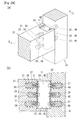
- Fig. 24 is a T-shaped connecting structure where an end surface of the counterpart member 51 contacts a side surface of the one member 41 in an upright position.
- Fig. 24 shows sectional views of the one member 41 and the counterpart member 51 taken along center lines of the pilot holes 46 and those of the pilot holes 56 respectively.
- the one member 41 and the counterpart member 51 are provided with the three pilot holes 46 and the three pilot holes 56 both arranged in a vertical fashion formed in the back surfaces of the upright grooves 44 and 54 respectively.
- the embedded shafts 21 are embedded in the two upper and lower pilot holes 46 and the two upper and lower pilot holes 56.
- the shafts 28 are embedded in the pilot hole 46 in the center and the pilot hole 56 in the center.
- the upright groove 44 in the one member 41 is formed in such a manner that the side surface of the one member 41 is hollowed out partially to form a downward surface 42 and the upward surface 45 facing each other.
- the connecting pipe 11 is fitted between the downward surface 42 and the upward surface 45.
- the connecting pipe 11 has the same shape as that shown for example in Fig. 1 .
- Fig. 25 shows a stage when the one member 41 and the counterpart member 51 of Fig. 24 are being connected.
- the two upper and lower embedded shafts 21 and the shaft 28 are embedded in the pilot holes 56 in the counterpart member 51.
- the two upper and lower embedded shafts 21 and the shaft 28 are also embedded in the pilot holes 46 in the one member 41.
- the connecting pipe 11 is fitted in the upright groove 54 in the counterpart member 51 and fixed with the bolts 31.
- the counterpart member 51 and the connecting pipe 11 integrated with the counterpart member 51 are raised and moved in a horizontal direction.
- the connecting pipe 11 is fitted in the upright groove 44 in the one member 41 and the bolts 31 are fastened from the inside of the connecting pipe 11. In this way, formation of a connection between the one member 41 and the counterpart member 51 is completed.
- Fig. 26 shows how the one member 41 and the counterpart member 51 of Fig. 24 are connected. Making the end surface of the counterpart member 51 contact the side surface of the one member 41 in this way forms a T-shaped connected part where the connecting pipe 11 is entirely embedded in the upright grooves 44 and 54.
- the counterpart member 51 illustrated in Fig. 26 may include the upper jaw 80 and the downward surface 52. In this case, considerations are to be given to the size of the upper jaw 80 so as not to interfere with fastening of the bolts 31, etc. Additionally, a procedure of construction is not limited to that shown in each of the drawings referred to previously. An optimum method can be selected in a manner that depends on circumstances.
Landscapes
- Engineering & Computer Science (AREA)
- Architecture (AREA)
- Physics & Mathematics (AREA)
- Electromagnetism (AREA)
- Civil Engineering (AREA)
- Structural Engineering (AREA)
- Joining Of Building Structures In Genera (AREA)
Abstract
Description
- This invention relates to a connecting structure between rod-shaped members such as a pillar and a horizontal member employed in various wooden structures including wooden buildings.
- Many wooden structures including wooden buildings have a framework formed by combining rod-shaped members such as a pillar and a horizontal member. A place where these members are connected is extremely important in terms of maintaining the strength of a construction. A fitting technique such as forming a connection or joint has been introduced for a long time. However, forming a connection or joint causes a problem in that these members require complicated processes. Thus, various metal fittings have been employed in recent years for a connection between members in many cases.
- Various techniques have been suggested relating to a connection between members. Examples of these techniques are described in patent literatures listed later.
Patent literature 1 discloses a framework method using a connecting metal fitting as an alternative to forming a connection or joint. In this method, a hole is formed in a piece of wood, a bolt is embedded in the hole, and the bolt is fixed to the piece of wood with a caulking material. A hollow connecting metal fitting is used for insertion of the bolt protruding from the piece of wood. The protruding bolt is inserted into the connecting metal fitting and a nut is threadedly engaged with the tip of the bolt and fastened. In this way, a plurality of pieces of wood can be connected via the connecting metal fitting. - Patent literature 2 discloses a drift pin used in a joint place between a pillar and a beam employed for example in a wooden framework structure. This drift pin has a dual structure including a tubular body and an engagement member like a thin rod inserted in the body. As a result of this structure, reaction force is generated in a direction where the drift pin expands, making it possible to prevent the drift pin from loosening due to aging degradation of members after construction. As illustrated in
Fig. 1 , etc. of this literature, a connecting metal fitting is embedded so as to straddle a boundary between two members to be joined. The connecting metal fitting has a shape like a thin box. The connecting metal fitting is embedded in a hole and a recess formed in the center of the boundary between the two members and is fixed with drift pins inserted from a side surface of a pillar or a beam. -
- Patent Literature 1: Japanese Patent Application Publication No.
Sho 52-56714 - Patent Literature 2: Japanese Patent Application Publication No.
2005-188722 - What is important for wooden buildings is to create a natural atmosphere resulting from trees to offer healing space for people. Thus, even if various metal fittings are used for a connection between members, considerations are given at a design stage or a construction stage in many cases so as to make the metal fittings completely invisible from indoor space. Further, the metal fittings bring about problems in that they become a cause for dew condensation as a result of a large difference in heat conductivity from wood, and that they are easy to brittle by heat occurring in case of fire. These problems may be overcome by embedding the metal fittings in the inside of wood for minimizing exposure of the metal fittings to the outside. In order to implement this means, however, considerations should be given to various factors such as construction performance, strength, and cost.
- The aforementioned connecting metal fitting disclosed in
patent literature 1 is caught in a boundary between two members, so that the existence thereof can easily be recognized visually from outside. The connecting metal fitting disclosed in patent literature 2 is embedded in the hole and the recess formed in the members. Thus, a side surface of this metal fitting is hidden completely. However, the upper surface and the lower surface of this metal fitting are exposed to the outside. Additionally, the opposite ends of the drift pin are also exposed to the outside. As described above, most of metal fittings currently used are exposed to the outside at least partially. - This invention has been developed based on the aforementioned actual circumstances. It is an object of this invention to provide a connecting structure between members employed in various wooden structures including wooden buildings where a metal fitting can be embedded in the members substantially entirely to achieve excellence in an aesthetic aspect, for example.
- To solve the aforementioned problem, the invention recited in
claim 1 is intended for a connecting structure between a one rod-shaped member and a counterpart rod-shaped member. The connecting structure uses: a hollow connecting pipe disposed to straddle contact surfaces with the one member and the counterpart member; and a fixing means including a bolt with which the connecting pipe is integrated with the one member and the counterpart member. The one member and the counterpart member include upright grooves configured to house the connecting pipe entirely. The upright grooves face each other to dispose the contact surfaces therebetween and extend vertically. The connecting pipe has a side surface provided with a lateral hole configured such that the fixing means including the bolt is inserted thereinto. The upright grooves extend toward without reaching a lower surface of the one member and a lower surface of the counterpart member. The upright grooves have respective bottoms serving as upward surfaces configured such that the connecting pipe is placed thereon. - This invention is to connect rod-shaped members in various wooden structures including wooden buildings. For the sake of convenience, a member closer to a foundation out of a plurality of members to be connected is referred to as a one member and a member to be supported in a suspended manner in the air by the one member is referred to as a counterpart member. A connected part between the one member and the counterpart member is required to form direct surface contact between these members. The members can be disposed freely. An L-shaped connected part or a T-shaped connected part may be formed by making a side surface of the one member and an end surface of the counterpart member contact each other. Alternatively, the members may be connected in a linear pattern by making respective end surfaces of the members contact each other. Still alternatively, a cross-shaped connected part may be formed by making end surfaces of the counterpart members contact opposite side surfaces of the one member.
- The connecting pipe is responsible for a connection between the one member and the counterpart member. The connecting pipe is formed by cutting a square steel pipe into a predetermined length, for example, and is used in an upright position. In this invention, a bolt and a nut should be placed and fastened in the connecting pipe, which requires a certain degree of space in the connecting pipe. The language "disposed to straddle the contact surfaces with the one member and the counterpart member" means that the connecting pipe crosses over the contact surfaces of the one member and the counterpart member to go into both of the members.
- The upright grooves are grooves formed in both of the one member and the counterpart member for housing of the connecting pipe. The upright grooves are required to extend in a linear pattern. Further, the upright grooves are responsible for hiding an entire side surface of the connecting pipe housed in the upright grooves. Thus, the depths of the upright grooves (distances from the corresponding contact surfaces) are ensured in such a manner that the connecting pipe can be housed in the upright grooves while the one member and the counterpart member contact each other to make the respective upright grooves face each other. However, the depths of the upright grooves in the one member and the counterpart member may differ from each other.
- The fixing means is used for fixing the connecting pipe to the one member and the counterpart member. The fixing means is formed of a lag screw to be embedded in the back surface of the upright groove, and a bolt or a nut to be threadedly engaged with the lag screw, for example. The fixing means to be used for forming a cross-shaped connected part where side surfaces of the one member are caught between the two counterpart members may include a stud bolt to penetrate opposite side surfaces of the one member and nuts to be threadedly engaged with opposite ends of the stud bolt. The lateral hole is provided in a side surface of the connecting pipe for insertion of this bolt, etc. The lateral hole is formed in a surface facing the back surface of the upright groove.
- The upright grooves extend vertically. Both of the upright grooves belonging to the one member and the counterpart member extend toward the lower surfaces of these members but do not reach the lower surfaces of these members. This makes the connecting pipe completely invisible from below. The bottoms of the upright grooves are referred to as upward surfaces. By placing the connecting pipe on the upward surfaces, a vertical load can be transmitted between the connecting pipe and the members. In order to reduce pressure to act on the upward surfaces, the lower surface of the connecting pipe may be covered. Additionally, in terms of ensuring the rigidity of the connected part, the upright grooves and the connecting pipe preferably have the same breadth.
- As described above, by fitting the connecting pipe in the upright grooves and integrating the connecting pipe with the one member and the counterpart member using the fixing means, the members can be connected via the connecting pipe. The upright grooves do not reach the lower surfaces of the members. This makes a metallic component completely invisible from a lateral side of the connected part or from below the connected part to create a natural atmosphere resulting from trees. The upper parts of the upright grooves cannot be hidden. However, a floor plate is placed on unhidden surfaces of these upper parts. Thus, the upright grooves are eventually hidden entirely.
- The connecting pipe has excellent rigidity against torsion or bending as a result of its shape. This necessarily enhances the rigidity of a connected part between the one member and the counterpart member. This effect is exerted most notably by fitting the connecting pipe in the upright grooves tightly. Additionally, the postures of the one member and the counterpart member after construction can be determined freely. In some place of construction, the upright grooves may not extend in a vertical direction.
- Another aspect of this invention is intended for a specific example of the fixing means. This aspect is characterized in that the fixing means is formed of an embedded shaft to be embedded in pilot holes formed in the back surfaces of the upright grooves and a bolt to be inserted into the lateral hole. A female screw is provided at an end surface of the embedded shaft to be threadedly engaged with the bolt.
- The embedded shaft is a rod-shaped metallic shaft such as a lag screw or deformed bar steel to be embedded in a member. The embedded shaft is inserted into the pilot hole formed in the back surface of the upright groove. The back surface of the upright groove is a surface located at the back of the upright groove and extending substantially parallel to the corresponding contact surface. The deformed bar steel is integrated with the member via an adhesive. A female screw is provided at an end surface of the embedded shaft (end surface exposed to the outside) to be threadedly engaged with the bolt.
- During construction, the upright grooves and the pilot holes are formed first and the embedded shafts are embedded and fixed in the pilot holes. Next, the connecting pipe is fitted in the upright groove in the counterpart member and the bolt is placed inside the connecting pipe thereafter. The tip of the bolt is inserted into the lateral hole, threadedly engaged with the female screw, and fastened. As described above, the female screw is provided at the end surface of the embedded shaft and the bolt is threadedly engaged with the female screw. As a result, the embedded shaft can be embedded entirely in the pilot hole. This reduces restrictions to form a contact between the one member and the counterpart member during construction. Thus, the one member and the counterpart member can be placed in their regular positions only by installing the one member and then moving down the counterpart member in a raised position gradually.
- Another aspect of this invention is intended to limit the shape of the upright grooves. This aspect is characterized in that the upright grooves are formed such that a surface of the one member or a surface of the counterpart member is hollowed out, and downward surfaces facing the upper surface of the connecting pipe are provided at upper parts of this upright grooves. As described above, the upright groove extends vertically and the top part of the upright groove reaches the upper surface of a member in many cases in consideration of performance during processing or construction. However, as in this invention, the upright groove can extend toward without reaching the upper surface of the member to form the downward surface.
- The downward surface necessarily faces the upward surface. The connecting pipe is caught between the downward surface and the upward surface. The downward surface and the upper surface of the connecting pipe can contact each other. In consideration of workability, etc., however, a certain degree of space may be formed between the downward surface and the upper surface of the connecting pipe. The upper part of the upright groove offers a working space for incorporation of the fixing means such as a bolt. Thus, the upper parts of the upright grooves extending over the one member and the counterpart member cannot be covered entirely. The range of the downward surface is limited to a part of each upright groove. A particular method of forming the downward surface can be determined freely.
- For example, the downward surface may be formed by a method of cutting a member into the upright groove in such a manner that a surface of the member is hollowed out and defining one inner surface of the upright groove as the downward surface. The downward surface may also be formed at the back of the upright groove by cutting the member into different depths at an upper part of the upright groove in such a manner that the upright groove reaches the upper surface of the member in a place near a surface of the member and that the upright groove does not reach the upper surface of the member in a place behind the place near the surface. The downward surface is not always provided to any one of the one member and the counterpart member but it can also be provided to both of these members. By making the upper surface of the connecting pipe contact the downward surface, a vertical load to act between the one member and the counterpart member can be transmitted partially through a surface of this contact. This can reduce a burden on a bolt, etc. to act more advantageously in terms of strength and reliability.
- According to this invention, the one member and the counterpart member can be connected via the connecting pipe by fitting the connecting pipe in the upright grooves and integrating the connecting pipe with the members using the fixing means. The upright grooves extend toward without reaching the lower surfaces of the members. Further, the fixing means is entirely embedded in the members or the connecting pipe. This makes a metallic component completely invisible from a lateral side of the connected part or from below the connected part to create a natural atmosphere resulting from trees.
- Further, the connecting pipe and the fixing means are entirely embedded in the members and can be isolated from external air completely by covering the upper parts of the upright grooves for example with a floor plate. This can prevent dew condensation from being caused by a difference in heat conductivity, and reduce temperature increase in case of fire, thereby enhancing the reliability of the connected part. The connecting pipe is placed on the upward surfaces at the bottoms of the upright grooves. Thus, a vertical load can be transmitted via these places to reduce a burden on the fixing means, contributing to increase in the strength of the connected part.
- According to the aspect of this invention, by forming the fixing means using the embedded shaft with a female screw provided at its end surface and the bolt to be threadedly engaged with the female screw, the embedded shaft can be embedded entirely in the members. This reduces restrictions to form a contact between the one member and the counterpart member during construction. In a specific example, the one member and the counterpart member can be placed in their regular positions only by installing the one member, attaching the connecting pipe to the counterpart member, and then moving down the counterpart member in a raised position gradually without requiring work of drawing the one member and the counterpart member toward each other and making the members contact each other tightly.
- According to the aspect of this invention, by providing the downward surface at the upper part of the upright groove, an upper part of the connecting pipe can also be hidden by the corresponding member. This acts more advantageously in terms of an aesthetic aspect and fire resistance. By making the upper surface of the connecting pipe and the downward surface contact each other, a vertical load is transmitted between this upper surface and the downward surface to reduce a load on a bolt, etc. This acts more advantageously in terms of strength and reliability.
-
-
Figs. 1(a) to 1(c) are perspective views showing an embodiment of a connecting structure according to this invention, in whichFig. 1(a) shows a one member, -
Fig. 1(b) shows how an L-shaped connected part is formed by making a side surface of the one member and an end surface of a counterpart member contact each other, andFig. 1(c) shows a connecting pipe in a state turned upside down,. -
Fig. 2(a) is a perspective view showing the counterpart member, andFig. 2(b) is a perspective view showing a stage when the one member and the counterpart member ofFig. 1 are being connected. -
Fig. 3(a) is a perspective view andFig. 3(b) is a sectional view taken along line A-A ofFig. 3(a) , both of which show how the one member and the counterpart member ofFig. 1 are connected. -
Fig. 4 is a perspective view showing a connecting structure of a cross shape as viewed from above where side surfaces of the one member are caught between the two counterpart members. -
Fig. 5(a) is a perspective view andFig. 5(b) is sectional view taken along line B-B ofFig. 5(a) , both of which show how the one member and the counterpart members ofFig. 4 are connected. -
Fig. 6 is a perspective view showing a connecting structure where the counterpart member extends in an oblique direction from a side surface of the one member. -
Fig. 7 is a perspective view similar to the perspective view ofFig. 6 and showing a connecting structure where the counterpart member extends in an oblique direction from a side surface of the one member and a connecting pipe has a cylindrical shape. -
Fig. 8(a) is a perspective view andFig. 8(b) is a sectional view taken along line C-C ofFig. 8(a) , both of which show a connecting structure where the counterpart member slopes downwardly for example at a roof part. -
Fig. 9 is a perspective view showing a connecting structure where a connecting pipe is placed on an upward surface of the one member and an upward surface of the counterpart member and additionally, an end portion of the counterpart member is placed on the one member. -
Fig. 10 is a perspective view showing a process of connecting the one member and the counterpart member ofFig. 9 . -
Fig. 11(a) is a perspective view showing a connecting structure where the one member and the counterpart member are connected in a linear pattern by making respective end surfaces of the one member and the counterpart member contact each other, andFig. 11(b) is a perspective view showing a connecting pipe ofFig. 11(a) in a state turned upside down. -
Fig. 12 is a perspective view showing a connecting structure where the two counterpart members are placed in a radial pattern along a side surface of the one member. -
Fig. 13(a) is a perspective view showing how the one member and the counterpart members ofFig. 12 are connected, andFig. 13(b) is a perspective view showing the structures of connecting pipes ofFig. 13(a) . -
Fig. 14 is a perspective view showing a cross-shaped connecting structure where side surfaces of the one member in an upright position are caught between the two counterpart members and a vertical member is connected to the one member in a position above the one member. -
Fig. 15 is a perspective view showing how the one member, the counterpart members, and the vertical member ofFig. 14 are connected. -
Fig. 16 is a perspective view showing a connecting structure of a cross shape as viewed from above where the counterpart member protrudes horizontally from each side surface of the one member in an upright position. -
Fig. 17 is a perspective view showing how the counterpart member is connected to each side surface of the one member ofFig. 16 . -
Fig. 18 is a perspective view showing a connecting structure where the counterpart members are attached to adjacent two of the four side surfaces of the one member and the vertical member is connected to the one member in a position above the one member. -
Fig. 19 is a perspective view showing a process of connecting the vertical member after the one member and the counterpart members ofFig. 18 are connected. -
Fig. 20(a) is a perspective view showing a connecting structure where a level difference is generated between an upward surface of an upright groove belonging to the one member and an upward surface of an upright groove belonging to the counterpart member, andFig. 20(b) is a perspective view showing a connecting pipe ofFig. 20(a) in a state turned upside down. -
Fig. 21(a) is a perspective view similar to the perspective view ofFig. 1 and showing an L-shaped connecting structure where a side surface of the one member and an end surface of the counterpart member contact each other and a downward surface is provided to the upright groove in the counterpart member, andFig. 21(b) is a perspective view showing a surface side of the one member opposite the surface side thereof shown inFig. 21(a) . -
Figs. 22(a) and 22(b) are perspective views showing a stage when the one member and the counterpart member ofFig. 21 are being connected. -
Fig. 23(a) is a perspective view andFig. 23(b) is a sectional view taken along line D-D ofFig. 23(a) , both of which show how the one member and the counterpart member ofFig. 21 are connected. -
Fig. 24 is a perspective view showing a T-shaped connecting structure where an end surface of the counterpart member contacts a side surface of the one member in an upright position and a downward surface is provided to the upright groove in the one member. -
Figs. 25(a) and 25(b) are perspective views showing a stage when the one member and the counterpart member ofFig. 24 are being connected. -
Fig. 26(a) is a perspective view andFig. 26(b) is a sectional view taken along line E-E ofFig. 26(a) , both of which show how the one member and the counterpart member ofFig. 24 are connected. -
Fig. 1 shows an embodiment of a connecting structure according to this invention. A side surface of a onemember 41 and an end surface of acounterpart member 51 contact each other to form an L-shaped connected part. Both the onemember 41 and thecounterpart member 51 are rod-shaped pieces of wood including laminated wood and have the same height. Thecounterpart member 51 is supported in a suspended manner in the air by the onemember 41. A part of the onemember 41 and a part of thecounterpart member 51 actually contacting each other are referred to as acontact surface 43 and acontact surface 53 respectively. Thecontact surface 53 of thecounterpart member 51 is an end surface thereof. Thecontact surface 43 of the onemember 41 is a region of the side surface thereof contacting thecounterpart member 51. A connectingpipe 11 and a fixing means are responsible for a connection between the onemember 41 and thecounterpart member 51. - The connecting
pipe 11 is a cutout from a general-purpose steel pipe and is smaller in breadth than thecounterpart member 51. Anupright groove 44 and anupright groove 54 are formed in the onemember 41 and thecounterpart member 51 respectively for housing of the connectingpipe 11. Theupright grooves upright grooves member 41 and thecounterpart member 51 respectively. Thus, anupward surface 45 and anupward surface 55 extending in a horizontal direction are formed at the bottoms of theupright grooves - The
upright grooves pipe 11 in an upright position to be housed entirely in theupright grooves upright grooves pipe 11 to be housed tightly in theupright grooves member 41 and thecounterpart member 51 contact each other. - The fixing means is to integrate the connecting
pipe 11 with the onemember 41 and thecounterpart member 51. The fixing means is formed of an embeddedshaft 21 using a lag screw and abolt 31 to be threadedly engaged with the embeddedshaft 21. The embeddedshaft 21 has a columnar shape with a lateral circumferential surface provided with athread 26 extending in a spiral pattern. The embeddedshaft 21 has ahead 25 for hang of a tool and afemale screw 27 for threaded engagement of thebolt 31 that are formed at one end surface of the embeddedshaft 21. Referring toFig. 1 (b) , the two upper and lower embeddedshafts 21 are embedded in each of the onemember 41 and thecounterpart member 51. In preparation therefor,pilot holes 46 andpilot holes 56 are formed in advance in the onemember 41 and thecounterpart member 51 respectively. Embedding the embeddedshafts 21 in the pilot holes 46 and the pilot holes 56 causes thethread 26 of the embeddedshafts 21 to be engaged with the peripheral surfaces of the pilot holes 46 and the pilot holes 56. In this way, the embeddedshafts 21 are fixed. - Referring to
Fig. 1(b) , ashaft 28, disposed in a position between the upper and lower embeddedshafts 21, is further embedded in each of the onemember 41 and thecounterpart member 51. Theshafts 28 have a simple columnar shape and are responsible for transmission of a load in a vertical direction. Similarly to the embeddedshafts 21, theshafts 28 are embedded in the pilot holes 46 and 56 formed in advance. The pilot holes 46 and 56 reasonably have an inner diameter that allows theshafts 28 to be housed tightly in the pilot holes 46 and 56. Each of theshafts 28 also has thehead 25 and thefemale screw 27 formed at one end surface of theshaft 28. - After the embedded
shafts 21 and theshafts 28 are embedded in the onemember 41 and thecounterpart member 51, the connectingpipe 11 is fitted in theupright grooves bolts 31 are inserted from the inside of the connectingpipe 11 toward thefemale screws 27, thereby connecting the onemember 41 and thecounterpart member 51 via the connectingpipe 11. The connectingpipe 11 has a side surface provided withlateral holes 38 for insertion of thebolts 31. The lateral holes 38 are adjusted in position so as to be aligned concentrically with the embeddedshafts 21 and theshafts 28. However, in consideration of construction work, thebolts 31 to be threadedly engaged with the lower embeddedshafts 21 are fitted inlateral grooves 37 as an alternative to the lateral holes 38. -
Fig. 2 shows a stage when the onemember 41 and thecounterpart member 51 ofFig. 1 are being connected. As illustrated inFig. 2(a) , the two upper and lower embeddedshafts 21 and theshaft 28 are embedded in the pilot holes 56 extending from the back surface of theupright groove 54 in thecounterpart member 51. All the embeddedshafts 21 and theshaft 28 are embedded in such a manner that their end surfaces are aligned with the back surface of theupright groove 54 without forming a level difference therebetween. As illustrated inFig. 2(b) , the two upper and lower embeddedshafts 21 and theshaft 28 are also embedded in the pilot holes 46 in the onemember 41. - After the embedded
shafts 21 and theshaft 28 are embedded in thecounterpart member 51, the connectingpipe 11 is fitted in theupright groove 54 and the lower part of the connectingpipe 11 is placed on theupward surface 55. As a result, the lateral holes 38 are aligned concentrically with thefemale screws 27 of the embeddedshafts 21 and thefemale screw 27 of the embeddedshaft 28. Next, thebolts 31 are placed in the connectingpipe 11 and the tips of thebolts 31 are inserted into the lateral holes 38 and thelateral groove 37. Thebolts 31 are threadedly engaged with thefemale screws 27 and fastened, thereby integrating the connectingpipe 11 and thecounterpart member 51. As shown inFig. 2(b) , thebolts 31 may be fastened by inserting a hexagon wrench B into the connectingpipe 11 and applying rotation to the wrench B gradually. - While the connecting
pipe 11 and thecounterpart member 51 are integrated, thebolt 31 is threadedly engaged with the lower embeddedshaft 21 in the onemember 41. At this stage, thisbolt 31 is not fastened but the head of thebolt 31 is floated on purpose to ensure a gap into which thelateral groove 37 is to be fitted. Then, thecounterpart member 51 is raised and the position of thecounterpart member 51 is adjusted in such a manner that the connectingpipe 11 comes to a position directly above theupright groove 44 in the onemember 41. Next, thecounterpart member 51 is moved down gradually to make the connectingpipe 11 start to enter theupright groove 44. When the shaft portion of thebolt 31 enters the inside of thelateral groove 37, separation between the onemember 41 and thecounterpart member 51 is prohibited. After the connectingpipe 11 contacts theupward surface 45 of the onemember 41, all thebolts 31 are fastened to complete formation of a connection between the onemember 41 and thecounterpart member 51. - The work of integrating the connecting
pipe 11 and thecounterpart member 51 can be done at a lumbering stage. This can reduce an workload at the work site. The connectingpipe 11 protrudes from the end surface of thecounterpart member 51, while no part of the connectingpipe 11 protrudes in the direction of a side surface of thecounterpart member 51. Thus, even if the connectingpipe 11 and thecounterpart member 51 are integrated at the lumbering stage, thecounterpart members 51 can still be stacked like square pieces of wood during storage or transportation. This achieves excellence in terms of cost and safety. -
Fig. 3 shows how the onemember 41 and thecounterpart member 51 ofFig. 1 are connected. Making the side surface of the onemember 41 and the end surface of thecounterpart member 51 contact each other in this way forms the L-shaped connected part where the connectingpipe 11 is entirely embedded in theupright grooves pipe 11 entirely contacts the onemember 41 and thecounterpart member 51 with the intention of enhancing the rigidity of the connected part. However, the upper surface of the connectingpipe 11 is placed at a height slightly lower than the upper surfaces of the onemember 41 and thecounterpart member 51. Thus, a floor plate F contacts the upper surfaces of the onemember 41 and thecounterpart member 51 tightly. Putting the floor plate F on the connectingpipe 11 hides the connectingpipe 11 completely, thereby offering excellent measure against dew condensation or fire. Additionally, the connectingpipe 11 contacts theupward surfaces counterpart member 51 is further received by theupward surface 45 of the onemember 41 to reduce a burden on the embeddedshafts 21 and theshafts 28. -
Fig. 4 shows a connecting structure of a cross shape as viewed from above where the side surfaces of the onemember 41 are caught between the twocounterpart members 51. The connectingpipe 11 used herein is exactly the same as the connectingpipe 11 used previously inFig. 1 . Further, each of the twocounterpart members 51 is exactly the same as the previously mentionedcounterpart member 51 in that theupright groove 54 is formed in an end surface and the embeddedshafts 21 and theshaft 28 are embedded in the back surface of theupright groove 54. However, regarding the onemember 41, theupright grooves 44 are formed in side surfaces to face in opposite directions. Further, the threepilot holes 46 arranged in a vertical fashion penetrate the opposite sides of the onemember 41. Each of embeddedshafts 22 and ashaft 29 to be embedded in the onemember 41 is provided with thefemale screws 27 formed at opposite end surfaces. Additionally, the embeddedshafts 22 and theshaft 29 all have the same entire length as the pilot holes 46. -
Fig. 5 shows how the onemember 41 and thecounterpart members 51 ofFig. 4 are connected. A cross-shaped connected part is formed by drawing thecounterpart members 51 toward the opposite side surfaces of the onemember 41. All metallic components including the connectingpipe 11, the embeddedshafts 21 and the embeddedshafts 22, and thebolts 31 are embedded inside to make these metallic components completely invisible from a lateral side or from below. As illustrated in the B-B cross section, thebolts 31 are threadedly engaged with the opposite end surfaces of each of the embeddedshafts 22 and theshaft 29 embedded in the onemember 41 to draw thecounterpart members 51 on the right and left of the onemember 41. -
Fig. 6 shows a connecting structure where thecounterpart member 51 extends in an oblique direction from a side surface of the onemember 41. The onemember 41 and thecounterpart member 51 in this structure are exactly the same as those of the aforementioned structure in that theupright groove 44 and the pilot holes 46 are formed in the onemember 41 and theupright groove 54 and the pilot holes 56 are formed in thecounterpart member 51, and the embeddedshafts 21 are embedded in the pilot holes 46 and the pilot holes 56. However, theupright groove 54 in thecounterpart member 51 extends in the longitudinal direction of thecounterpart member 51, so that an end surface of thecounterpart member 51 and the back surface of theupright groove 54 do not extend parallel to each other. In response, a connectingpipe 12 has a polygonal shape bent at some point so as not to form a gap between the connectingpipe 12 and each of theupright grooves member 41 and thecounterpart member 51 are to intersect with each other at a different angle, this connectingpipe 12 becomes unusable. - In
Fig. 6 , the onemember 41 and thecounterpart member 51 are respectively provided with the twopilot holes 46 arranged in a vertical fashion and the twopilot holes 56 also arranged in a vertical fashion and do not have theshaft 28 such as that ofFig. 1 , etc. Additionally, thelateral groove 37 is not formed in the connectingpipe 12. Thus, this invention is characterized in that the onemember 41 and thecounterpart member 51 are provided with theupright grooves member 41 and thecounterpart member 51 respectively and the connectingpipe 12 is housed in theupright grooves shaft 21 and theshaft 28, and the number of the embeddedshafts 21 and the number of theshafts 28 can be determined freely. - Similarly to
Fig. 6 ,Fig. 7 shows a connecting structure where thecounterpart member 51 extends in an oblique direction from a side surface of the onemember 41. A connectingpipe 13 is formed into a cylindrical shape so as to follow a change in an angle of intersection. Lateral holes 39 in the connectingpipe 13 are transversely extending long holes. Thus, even if the onemember 41 and thecounterpart member 51 are to intersect with each other at a different angle, thebolts 31 can still be inserted without difficulty. This makes the connectingpipe 13 usable without reliance on an angle of intersection. - To stabilize the head of each
bolt 31, adedicated washer 35 is used. One surface of thewasher 35 is curved so as to contact the inner circumferential surface of the connectingpipe 13 tightly. Unlike the connecting pipes described above, the connectingpipe 13 is not allowed to be in surface contact with each of theupright grooves pipe 13 is caught in theupright grooves -
Fig. 8 shows a connecting structure where thecounterpart member 51 slopes downwardly at a roof part, for example. In this structure, the onemember 41 is placed in a horizontal direction and thecounterpart member 51 protrudes obliquely downwardly from a side surface of the onemember 41. Similarly to the aforementioned structures, theupright groove 44 is formed in the side surface of the onemember 41. However, theupright groove 54 and the pilot holes 56 are formed in thecounterpart member 51 with respect to the longitudinal direction of thecounterpart member 51. Thus, an end surface of thecounterpart member 51 and the back surface of theupright groove 54 do not extend parallel to each other. - A connecting
pipe 14 used in this structure is narrowed toward the bottom as viewed from a lateral side, so that the connectingpipe 14 is allowed to contact the back surfaces of theupright grooves member 41 and the side of thecounterpart member 51. Further, the upper end of the connectingpipe 14 is formed into a sloping surface so as not to protrude upwardly from theupright grooves counterpart member 51 slopes upwardly conversely to the structure ofFig. 8 , this invention can still be introduced reasonably by adjusting the shape of a connecting pipe, for example. -
Fig. 9 shows a connecting structure where a connectingpipe 15 is placed on theupward surfaces member 41 and thecounterpart member 51 respectively, and additionally, an end portion of thecounterpart member 51 is placed on the onemember 41. If each part is deformed further with age after construction, a slight gap may occur between the onemember 41 and thecounterpart member 51. Even in this case, a problem in terms of strength is not caused. However, this slight gap may cause a problem in terms of appearance. Then, as shown inFig. 9 , the height of thecounterpart member 51 may be reduced compared to that of the onemember 41. Further, the onemember 41 may have a dual structure with anexternal groove 47 formed in a side surface thereof and theupright groove 44 formed inside theexternal groove 47. Additionally, aplacement surface 48 may be formed at one level lower than theupward surface 45. - The
external groove 47 has such a size that the end portion of thecounterpart member 51 is fitted in theexternal groove 47 tightly. If the onemember 41 and thecounterpart member 51 are actually fitted to each other, their respectiveupward surfaces shafts 21 are embedded in each of the onemember 41 and thecounterpart member 51. In preparation therefor, the upper and lowerlateral holes 38 are formed in the connectingpipe 15. -
Fig. 10 shows a process of connecting the onemember 41 and thecounterpart member 51 shown inFig. 9 . The embeddedshafts 21 are embedded in each of the onemember 41 and thecounterpart member 51. Further, the connectingpipe 15 is fixed in theupright groove 54 in thecounterpart member 51. Next, the connectingpipe 15 protruding from thecounterpart member 51 is fitted in theupright groove 44 in the onemember 41 and thebolts 31 are fastened. In this way, formation of a connection is completed. The end portion of thecounterpart member 51 is fitted in theexternal groove 47 in the onemember 41 and the lower surface of thecounterpart member 51 is received on theplacement surface 48. Thus, a load acting downwardly on thecounterpart member 51 is transmitted reliably to the onemember 41. Even if the onemember 41 and thecounterpart member 51 are separated from each other slightly after construction, the appearance does not change as long as thecounterpart member 51 is fitted in theexternal groove 47. -
Fig. 11 shows a connecting structure where the onemember 41 and thecounterpart member 51 are connected in a linear pattern by making respective end surfaces of the onemember 41 and thecounterpart member 51 contact each other. In this structure, theupright grooves member 41 and thecounterpart member 51 respectively. Wood screws 32 are used as means of fixing a connectingpipe 16 and thecounterpart member 51. The two upper and lower wood screws 32 are to be used. In preparation therefor, the lateral holes 38 formed on one side of the connectingpipe 16 are increased in inner diameter. Embeddedshafts 23 as cutouts from deformed bar steel are used as means of fixing the connectingpipe 16 and the onemember 41. Each embeddedshaft 23 has a lateral circumferential surface provided withribs 24 and an end surface provided with thefemale screw 27. After being coated with an adhesive A, the embeddedshafts 23 are embedded in the pilot holes 46 formed in the back surface of theupright groove 44. - The lower surface of the connecting
pipe 16 is covered with abottom plate 36 except an area in the vicinity of thelateral groove 37. This increases an area of contact with each of theupward surfaces member 41 and thecounterpart member 51 ofFig. 11 , the connectingpipe 16 is first fitted in theupright groove 54 in thecounterpart member 51, and the connectingpipe 16 and thecounterpart member 51 are integrated with the wood screws 32. Next, the embeddedshafts 23 are fixed in the pilot holes 46 in the onemember 41 with the adhesive A. Then, thebolt 31 to be fitted in thelateral groove 37 is threadedly engaged with the lower embeddedshaft 23. Finally, the connectingpipe 16 protruding from thecounterpart member 51 in a raised position is placed on the onemember 41 and thebolt 31 belonging to the onemember 41 is fastened, thereby completing the work. As described above, various members such as thebolt 31, a lag screw, thewood screw 32, and deformed bar steel are applicable as the fixing means. -
Fig. 12 shows a connecting structure where the twocounterpart members 51 are placed in a radial pattern along a side surface of the onemember 41. In many cases of general bracing or trussing, multiple members are connected in one place. This invention can also be applied to such a situation. Referring toFig. 12 , the twocounterpart members 51 are connected to the side surface of the onemember 41. Two connecting pipes including a connectingpipe 17a and a connectingpipe 17b are used. The connectingpipe 17a and the connectingpipe 17b have trapezoidal shapes corresponding to angles of intersection of thecounterpart members 51. Theupright grooves 54 formed in thecounterpart members 51 are each opened only at one side surface side (a side contacting the adjacent counterpart member 51). Similarly to the aforementioned structures, the embeddedshafts 21 are embedded in the pilot holes 56 in the back surface of eachupright groove 54. - The connecting
pipe 17a illustrated in the upper left area is fixed in theupright groove 54 in theleft counterpart member 51. The connectingpipe 17b illustrated in the upper right area is fixed in theupright groove 54 in theright counterpart member 51. Fitting both the connectingpipes upright groove 44 in the onemember 41 makes respective side surfaces of the two connectingpipes holes 63 through which the two connectingpipes counterpart members 51 extend in the longitudinal directions of the corresponding members. Further, the back surfaces of theupright grooves 54 are perpendicular to the longitudinal directions of the corresponding members. -
Fig. 13 shows how the onemember 41 and thecounterpart members 51 ofFig. 12 are connected. As shown inFig. 13 , the twocounterpart members 51 contact each other at their end portions and their neighboring portions. Thus, the lower surfaces and the side surfaces of the two connectingpipes pipes corresponding counterpart members 51, and then thecounterpart members 51 are connected to the onemember 41 one by one. At this time, the two connectingpipes counterpart members 51 are connected, hold-downbolts 61 are inserted into the hold-downholes 63, andnuts 62 are threadedly engaged with the tips of the hold-downbolts 61 and fastened, thereby integrating the connectingpipes -
Fig. 14 shows a cross-shaped connecting structure where side surfaces of the onemember 41 in an upright position are caught between the twocounterpart members 51 and avertical member 71 is connected to the onemember 41 in a position above the onemember 41. The twocounterpart members 51 are disposed to face each other relative to the onemember 41. Thevertical member 71 is connected to the onemember 41 via amortise pipe 64. During construction, the two embeddedshafts 21 and theshaft 28 are embedded in each of thecounterpart members 51 first to fix the connectingpipe 11 in theupright groove 54. Next, using a fixing means formed ofstud bolts 34 andnuts 33 to be threadedly engaged with the opposite ends of eachstud bolt 34, the twocounterpart members 51 facing each other are drawn toward the onemember 41. - The one
member 41 is provided with theupright grooves 44 for housing of the connectingpipes 11 and the pilot holes 46 for insertion of thestud bolts 34. Theupright grooves 44 are formed on both of the right and left sides. The pilot holes 46 penetrate both of these sides. Additionally, thevertical member 71 is connected to the onemember 41 via themortise pipe 64. In preparation therefor, acenter hole 49 for insertion of themortise pipe 64 is formed in the center of the upper surface of the onemember 41. Thecenter hole 49 crosses the pilot holes 46. Inserting thestud bolts 34 into themortice pipe 64 integrates themortise pipe 64 and the onemember 41. Likewise, acenter hole 74 is formed in the center of the lower surface of thevertical member 71. After themortise pipe 64 is inserted into thecenter hole 74, themortise pipe 64 and thevertical member 71 are integrated with fixing pins 66. For insertion of the fixing pins 66, pin holes 72 are formed in side surfaces of thevertical member 71. Further, for insertion of thestud bolts 34 and the fixing pins 66, round holes 65 are formed in the lateral circumferential surface of themortise pipe 64. -
Fig. 15 shows how the onemember 41, thecounterpart members 51, and thevertical member 71 ofFig. 14 are connected. As shown inFig. 15 , the twocounterpart members 51 are drawn toward the side surface of the onemember 41 with thestud bolts 34 and the nuts 33 at the opposite ends of eachstud bolt 34. As will be understood, the lower surfaces and the side surfaces of the connectingpipes 11 are hidden completely. Further, the onemember 41 and thevertical member 71 are integrated with themortise pipe 64, thestud bolts 34, and the fixing pins 66. The onemember 41 and thevertical member 71 have the same sectional shape and are aligned without any level difference to substantially function as one pillar. -
Fig. 16 shows a connecting structure of a cross shape as viewed from above where thecounterpart member 51 protrudes horizontally from each side surface of the onemember 41 in an upright position. Referring toFig. 16 , the two embeddedshafts 21 are embedded in eachcounterpart member 51 and a connectingpipe 18 is fixed in theupright groove 54 in eachcounterpart member 51. The twocounterpart members 51 facing each other to dispose the onemember 41 therebetween are drawn with thestud bolts 34 and thenuts 33 threadedly engaged with the opposite ends of eachstud bolt 34. In preparation therefor, the pilot holes 46 penetrating the opposite sides of the onemember 41 are formed in the back surfaces of theupright grooves 44. Thestud bolts 34 are inserted in two directions perpendicular to each other. To allow thestud bolts 34 to cross each other at different levels inside the onemember 41, the heights of the pilot holes 46 are changed depending on their directions. Further, the lateral holes 38 are formed in each side surface of the connectingpipe 18 with the intention of ensuring versatility of the connectingpipe 18. The heights of the lateral holes 38 are changed between adjacent side surfaces. InFig. 16 , the four connectingpipes 18 have the same shape. -
Fig. 17 shows how thecounterpart member 51 is connected to each side surface of the onemember 41 ofFig. 16 . As shown inFig. 17 , the lower surface and the side surface of each connectingpipe 18 are hidden completely, whereas the upper surface of each connectingpipe 18 is exposed to the outside. If the upper surface of each connectingpipe 18 is also to be hidden, a blocking plate P to be fitted in theupright grooves member 41 and thecounterpart member 51, the existence of the connectingpipes 18 and those of theupright grooves -
Fig. 18 shows a connecting structure where thecounterpart members 51 are attached to adjacent two of the four side surfaces of the onemember 41 and thevertical member 71 is connected to the onemember 41 in a position above the onemember 41. The two right and left side surfaces of the onemember 41 are each provided with theupright groove 44 and the pilot holes 46. The pilot holes 46 have closed bottoms. The heights of the pilot holes 46 differ between the right and left sides. Connectingpipes 19 on the right and left sides have the same shape. One of the side surfaces of each connectingpipe 19 facing the onemember 41 is provided with the fourlateral holes 38 arranged in a vertical fashion. Further, the height of theupright grooves 44 exceeds that of thecounterpart members 51, and only the onemember 41 protrudes upwardly. - The one
member 41 and thevertical member 71 are connected via astud bolt 77. Thecenter hole 49 for screwing-in of alower lag screw 76 is formed in the center of the upper surface of the onemember 41. A female screw is formed at an upper end surface of thelower lag screw 76. A lower part of thestud bolt 77 can be threadedly engaged with this female screw. Further, thecenter hole 74 is formed in the center of the lower surface of thevertical member 71. Additionally, arectangular side window 73 continuous with thecenter hole 74 is formed in a side surface of thevertical member 71. -
Fig. 19 shows a process of connecting thevertical member 71 after the onemember 41 and thecounterpart members 51 ofFig. 18 are connected. The twocounterpart members 51 are disposed at right angles. Both thecounterpart members 51 are connected to side surfaces of the onemember 41. Thelower lag screw 76 is screwed into thecenter hole 49 in the onemember 41 and thestud bolt 77 is threadedly engaged with thelower lag screw 76. - An
upper lag screw 78 is screwed into thecenter hole 74 in thevertical member 71. Theupper lag screw 78, which has a hollow shape, allows thestud bolt 77 protruding from the onemember 41 to pass through. By placing thevertical member 71 directly above the onemember 41, the upper end of thestud bolt 77 goes through theupper lag screw 78 to reach the inside of theside window 73. Then, anut 79 and awasher 75 are inserted via theside window 73, and thenut 79 is threadedly engaged with thestud bolt 77 and fastened. As a result, thevertical member 71 is drawn toward the onemember 41 to complete formation of every connection. -
Fig. 20 is a perspective view showing a connecting structure where a level difference is generated between theupward surfaces upright grooves member 41 and thecounterpart member 51 respectively. As inFig. 20(a) , if the onemember 41 and thecounterpart member 51 have different heights to generate a level difference between the respectiveupward surfaces pipe 20 to contact both the onemember 41 and thecounterpart member 51 by forming a corresponding level difference at a lower part of the connectingpipe 20. In this connecting structure, a lower part of theupright groove 54 belonging to thecounterpart member 51 is exposed to the outside. However, by introducing a pillar illustrated with alternate long and two short dashed lines, this lower part can be hidden. In a connecting structure such as that shown inFig. 8 where the onemember 41 or thecounterpart member 51 slopes upwardly or downwardly, a level difference may also be generated between theupward surfaces pipe 20 as inFig. 20(b) . - Similarly to
Fig. 1 ,Fig. 21 shows an L-shaped connecting structure where a side surface of the onemember 41 and an end surface of thecounterpart member 51 contact each other. Theupright groove 54 in thecounterpart member 51 includes adownward surface 52.Fig. 21 shows sectional views of the onemember 41 and thecounterpart member 51 taken along center lines of the pilot holes 46 and those of the pilot holes 56 respectively. The onemember 41 and thecounterpart member 51 are provided with the threepilot holes 46 and the threepilot holes 56 both arranged in a vertical fashion formed in the back surfaces of theupright grooves shafts 21 are embedded in the two upper andlower pilot holes 46 and the two upper and lower pilot holes 56. Theshafts 28 are embedded in thepilot hole 46 in the center and thepilot hole 56 in the center. Theupright grooves member 41 and the end surface of thecounterpart member 51. Theupright groove 44 in the onemember 41 has the same form as that illustrated in each drawing referred to previously. However, theupright groove 54 in thecounterpart member 51 is provided with anupper jaw 80 covering substantially an upper half of theupright groove 54 as well as theupward surface 55 described previously. - The
upper jaw 80 is formed by adjusting a range of cutting for formation of theupright groove 54. The lower surface of theupper jaw 80 is defined as thedownward surface 52. Thedownward surface 52 faces theupward surface 55. The dimension of thedownward surface 52 is adjusted so as to allow a connectingpipe 10 to be caught between thedownward surface 52 and theupward surface 55. A general-purpose steel pipe is used as the connectingpipe 10. The connectingpipe 10 is provided with the lateral holes 38 and thelateral grooves 37 formed in side surfaces of the connectingpipe 10. The upper surface of the connectingpipe 10 is partially covered with atop plate 67. Thetop plate 67 is to contact thedownward surface 52 of thecounterpart member 51 and has a size that does not interfere with fastening of thebolt 31, for example. -
Fig. 22 shows a stage when the onemember 41 and thecounterpart member 51 ofFig. 21 are being connected. As illustrated inFig. 22(a) , the two upper and lower embeddedshafts 21 and theshaft 28 are embedded in the pilot holes 56 in thecounterpart member 51. As illustrated inFig. 22(b) , the two upper and lower embeddedshafts 21 and theshaft 28 are also embedded in the pilot holes 46 in the onemember 41. - After the embedded
shafts 21 and theshaft 28 are embedded in thecounterpart member 51, the connectingpipe 10 is fitted in theupright groove 54. This makes the lower surface of the connectingpipe 10 contact theupward surface 55, while making the upper surface of the connecting pipe 10 (including the top plate 67) contact thedownward surface 52. Next, thebolts 31 are placed in the connectingpipe 10, and the tips of thebolts 31 are inserted into the lateral holes 38 and thelateral groove 37. Thebolts 31 are threadedly engaged with thefemale screws 27 and fastened, thereby integrating the connectingpipe 10 and thecounterpart member 51. Considerations are given to the shape and the size of theupper jaw 80 of thecounterpart member 51 as well as thetop plate 67 of the connectingpipe 10 so as not to interfere with fastening of thebolts 31, etc. - Then, only a tip portion of the
bolt 31 is threadedly engaged with the lower embeddedshaft 21 in the onemember 41, and thecounterpart member 51 in a raised position is moved down gradually to start fitting the connectingpipe 10 in theupright groove 44 in the onemember 41. Then, the shaft portion of theaforementioned bolt 31 enters the inside of thelateral groove 37. Finally, the connectingpipe 10 contacts theupward surface 45 of the onemember 41. By fastening all thebolts 31 from the inside of the connectingpipe 10 thereafter, formation of a connection between the onemember 41 and thecounterpart member 51 is completed. -
Fig. 23 shows how the onemember 41 and thecounterpart member 51 ofFig. 21 are connected. Making the side surface of the onemember 41 and the end surface of thecounterpart member 51 contact each other in this way forms an L-shaped connected part where the connectingpipe 10 is entirely embedded in theupright grooves pipe 10 including thetop plate 67 contacts thedownward surface 52 of thecounterpart member 51. Thus, a load acting downwardly on thecounterpart member 51 is transmitted to the connectingpipe 10 via a surface of this contact to reduce a burden on the embeddedshafts 21 and theshafts 28, thereby enhancing reliability. In consideration of construction performance, for example, a gap may be formed on purpose between the connectingpipe 10 and thedownward surface 52. InFig. 23 , theupper jaw 80 is located behind the end surface of thecounterpart member 51 in order to ensure a working space. However, if theupright groove 44 in the onemember 41 can be formed to be deeper, theupper jaw 80 can extend to the end surface of thecounterpart member 51 to cover the upper part of theupright groove 54 entirely. -
Fig. 24 is a T-shaped connecting structure where an end surface of thecounterpart member 51 contacts a side surface of the onemember 41 in an upright position.Fig. 24 shows sectional views of the onemember 41 and thecounterpart member 51 taken along center lines of the pilot holes 46 and those of the pilot holes 56 respectively. The onemember 41 and thecounterpart member 51 are provided with the threepilot holes 46 and the threepilot holes 56 both arranged in a vertical fashion formed in the back surfaces of theupright grooves shafts 21 are embedded in the two upper andlower pilot holes 46 and the two upper and lower pilot holes 56. Theshafts 28 are embedded in thepilot hole 46 in the center and thepilot hole 56 in the center. Theupright groove 44 in the onemember 41 is formed in such a manner that the side surface of the onemember 41 is hollowed out partially to form adownward surface 42 and theupward surface 45 facing each other. The connectingpipe 11 is fitted between thedownward surface 42 and theupward surface 45. The connectingpipe 11 has the same shape as that shown for example inFig. 1 . -
Fig. 25 shows a stage when the onemember 41 and thecounterpart member 51 ofFig. 24 are being connected. As illustrated inFig. 25(a) , the two upper and lower embeddedshafts 21 and theshaft 28 are embedded in the pilot holes 56 in thecounterpart member 51. As illustrated inFig. 25(b) , the two upper and lower embeddedshafts 21 and theshaft 28 are also embedded in the pilot holes 46 in the onemember 41. Further, the connectingpipe 11 is fitted in theupright groove 54 in thecounterpart member 51 and fixed with thebolts 31. Thecounterpart member 51 and the connectingpipe 11 integrated with thecounterpart member 51 are raised and moved in a horizontal direction. Further, the connectingpipe 11 is fitted in theupright groove 44 in the onemember 41 and thebolts 31 are fastened from the inside of the connectingpipe 11. In this way, formation of a connection between the onemember 41 and thecounterpart member 51 is completed. -
Fig. 26 shows how the onemember 41 and thecounterpart member 51 ofFig. 24 are connected. Making the end surface of thecounterpart member 51 contact the side surface of the onemember 41 in this way forms a T-shaped connected part where the connectingpipe 11 is entirely embedded in theupright grooves Fig. 21 , thecounterpart member 51 illustrated inFig. 26 may include theupper jaw 80 and thedownward surface 52. In this case, considerations are to be given to the size of theupper jaw 80 so as not to interfere with fastening of thebolts 31, etc. Additionally, a procedure of construction is not limited to that shown in each of the drawings referred to previously. An optimum method can be selected in a manner that depends on circumstances. -
- 10 Connecting pipe (with top plate)
- 11 Connecting pipe
- 12 Connecting pipe (polygonal shape)
- 13 Connecting pipe (cylindrical shape)
- 14 Connecting pipe (used for connection of sloping member)
- 15 Connecting pipe (without lateral groove)
- 16 Connecting pipe (with bottom plate)
- 17a, 17bConnecting pipes (two connecting pipes in pair)
- 18 Connecting pipe (including lateral hole formed in each side surface)
- 19 Connecting pipe (including lateral hole in position differing between opposite surfaces)
- 20 Connecting pipe (with level difference at lower part)
- 21 Embedded shaft (fixing means with female screw at one end surface)
- 22 Embedded shaft (fixing means with female screws at opposite end surfaces)
- 23 Embedded shaft (fixing means, deformed bar steel)
- 24 Rib
- 25 Head
- 26 Thread
- 27 Female screw
- 28 Shaft (with female screw at one end surface)
- 29 Shaft (with female screws at opposite end surfaces)
- 31 Bolt (fixing means)
- 32 Wood screw (fixing means)
- 33 Nut (fixing means)
- 34 Stud bolt (fixing means)
- 35 Washer
- 36 Bottom plate
- 37 Lateral groove
- 38 Lateral hole
- 39 Lateral hole (oval shape)
- 41 One member
- 42 Downward surface
- 43 Contact surface
- 44 Upright groove
- 45 Upward surface
- 46 Pilot hole
- 47 External groove
- 48 Placement surface
- 49 Center hole
- 51 Counterpart member
- 52 Downward surface
- 53 Contact surface
- 54 Upright groove
- 55 Upward surface
- 56 Pilot hole
- 61 Hold-down bolt
- 62 Nut
- 63 Hold-down hole
- 64 Mortise pipe
- 65 Round hole
- 66 Fixing pin
- 67 Top plate
- 71 Vertical member
- 72 Pin hole
- 73 Side window
- 74 Center hole
- 75 Washer
- 76 Lower lag screw (belonging to one member)
- 77 Stud bolt
- 78 Upper lag screw (belonging to vertical member)
- 79 Nut
- 80 Upper jaw
- A Adhesive
- B Hexagon wrench
- F Floor plate
- P Blocking plate
- PI Pillar
Claims (3)
- A connecting structure between a one rod-shaped member (41) and a counterpart rod-shaped member (51),
the connecting structure using:a hollow connecting pipe (10 to 20) disposed to straddle contact surfaces (43, 53) with the one member (41) and the counterpart member (51); anda fixing means including a bolt (31) with which the connecting pipe (10 to 20) is integrated with the one member (41) and the counterpart member (51),the one member (41) and the counterpart member (51) including upright grooves (44, 54) configured to house the connecting pipe (10 to 20) entirely, the upright grooves (44, 54) facing each other to dispose the contact surfaces (43, 53) therebetween and extending vertically,
the connecting pipe (10 to 20) having a side surface provided with a lateral hole (38) configured such that the fixing means including the bolt is inserted thereinto (31),
the upright grooves (44, 54) extending toward without reaching a lower surface of the one member (41) and a lower surface of the counterpart member (51), and
the upright grooves (44, 54) having respective bottoms serving as upward surfaces (45, 55) configured such that the connecting pipe is placed thereon (10 to 20). - The connecting structure according to claim 1, wherein
the fixing means is formed of an embedded shaft (21, 22, or 23) to be embedded in pilot holes (46, 56) formed in back surfaces of the upright grooves (44, 54) and the bolt (31) to be inserted into the lateral hole (38), and
the embedded shaft (21, 22, or 23) has an end surface where a female screw (27) is provided to be threadedly engaged with the bolt (31). - The connecting structure according to claim 1 or 2, wherein
the upright grooves (44, 54) are formed such that a surface of the one member (41) or the counterpart member (51) is hollowed out, and
downward surfaces (42, 52) facing an upper surface of the connecting pipe (10 to 20) are provided at upper parts of the upright grooves (44, 54).
Applications Claiming Priority (3)
| Application Number | Priority Date | Filing Date | Title |
|---|---|---|---|
| JP2013230572 | 2013-11-06 | ||
| JP2014012698A JP6280755B2 (en) | 2013-11-06 | 2014-01-27 | Connected structure |
| PCT/JP2014/079293 WO2015068710A1 (en) | 2013-11-06 | 2014-11-05 | Joint structure |
Publications (3)
| Publication Number | Publication Date |
|---|---|
| EP3067480A1 true EP3067480A1 (en) | 2016-09-14 |
| EP3067480A4 EP3067480A4 (en) | 2017-06-07 |
| EP3067480B1 EP3067480B1 (en) | 2019-06-05 |
Family
ID=53041487
Family Applications (1)
| Application Number | Title | Priority Date | Filing Date |
|---|---|---|---|
| EP14860046.3A Not-in-force EP3067480B1 (en) | 2013-11-06 | 2014-11-05 | Connecting structure |
Country Status (4)
| Country | Link |
|---|---|
| US (1) | US20160289949A1 (en) |
| EP (1) | EP3067480B1 (en) |
| JP (1) | JP6280755B2 (en) |
| WO (1) | WO2015068710A1 (en) |
Cited By (1)
| Publication number | Priority date | Publication date | Assignee | Title |
|---|---|---|---|---|
| US20190161957A1 (en) * | 2016-06-27 | 2019-05-30 | Loggo Ip Pty Ltd | Apparatus and Methods For Connecting Timber Flanges |
Families Citing this family (7)
| Publication number | Priority date | Publication date | Assignee | Title |
|---|---|---|---|---|
| JP6599178B2 (en) * | 2015-08-28 | 2019-10-30 | 憲峰 大倉 | Connected structure |
| JP6503314B2 (en) * | 2016-04-05 | 2019-04-17 | 大倉 憲峰 | Connected structure |
| JP7188094B2 (en) * | 2019-01-09 | 2022-12-13 | 積水ハウス株式会社 | roof structure |
| CA3045195A1 (en) * | 2019-06-04 | 2020-12-04 | Lakehead University | Timber beam end connection using embedded mechanical fastening |
| JP7161223B2 (en) * | 2020-02-07 | 2022-10-26 | 株式会社ストローグ | connector |
| RU198878U1 (en) * | 2020-04-17 | 2020-07-30 | Павел Сергеевич Булыгин | CONNECTING UNIT OF EXTENDED WOODEN ELEMENTS |
| US20220112709A1 (en) * | 2020-10-09 | 2022-04-14 | Shibusa LLC | Wood timber framing method |
Family Cites Families (27)
| Publication number | Priority date | Publication date | Assignee | Title |
|---|---|---|---|---|
| US733500A (en) * | 1902-11-17 | 1903-07-14 | Stephen W Moore | Compound bevel-joint. |
| US3049197A (en) * | 1961-03-22 | 1962-08-14 | Oskar R Ludwig | Flush single-line partitions |
| US3884002A (en) * | 1973-03-15 | 1975-05-20 | American Store Equip | Partition system |
| JPS5814533B2 (en) | 1975-11-01 | 1983-03-19 | ミズグチ トモトシ | SetsugouyoukanagouoshiyousuruJikugumikohou |
| US4601137A (en) * | 1983-07-29 | 1986-07-22 | The Tandem Group, Inc. | Locking mechanism for an office panel system |
| US4956953A (en) * | 1989-03-08 | 1990-09-18 | Bates Norman H | Office panel system incorporating improved locking and alignment mechanism |
| JPH0346688U (en) * | 1989-09-04 | 1991-04-30 | ||
| US5284311A (en) * | 1990-10-29 | 1994-02-08 | Newco, Inc. | Hook bracket and kit for storage structure |
| US5061111A (en) * | 1991-01-02 | 1991-10-29 | Kiyoshi Hosokawa | Metal connector for wooden building and jointing structure of wooden building using the same |
| JPH0754405Y2 (en) * | 1991-03-11 | 1995-12-18 | 清司 細川 | Fasteners for wooden building materials and fastening structures for wooden buildings |
| JP2514125Y2 (en) * | 1992-10-07 | 1996-10-16 | セブン工業株式会社 | Structural laminated wood with joint fittings |
| US5438811A (en) * | 1993-03-22 | 1995-08-08 | Shigeo Goya | Jointing metal fixture for construction |
| JPH0835261A (en) * | 1994-07-22 | 1996-02-06 | Daiichi Shoten:Kk | Metallic connector for wood structure in building and erecting method for building by means thereof |
| JP2967048B2 (en) * | 1996-04-23 | 1999-10-25 | 院庄林業株式会社 | Connection structure of horizontal member of framed wooden building |
| JP3066734B2 (en) * | 1996-11-15 | 2000-07-17 | 株式会社ウエスト | Equipment for wooden building framing |
| JP3066735B2 (en) * | 1996-11-19 | 2000-07-17 | 株式会社ウエスト | Timber pillar connection fitting of wooden building |
| JP3390823B2 (en) * | 1996-11-20 | 2003-03-31 | 株式会社ウエスト | Equipment for wooden building frames |
| JP2000192556A (en) * | 1998-12-25 | 2000-07-11 | Okada Kinzoku Kogyosho:Kk | Joining fixing fitting for wood |
| US6503020B1 (en) * | 2000-07-14 | 2003-01-07 | Marco Mascioletti | Connector system for structural members |
| US6625945B2 (en) * | 2000-08-08 | 2003-09-30 | Alfred D. Commins | Balanced, multi-stud hold-down |
| JP2005188722A (en) * | 2003-12-26 | 2005-07-14 | Topics:Kk | Drift pin |
| JP4546915B2 (en) * | 2005-11-14 | 2010-09-22 | 有限会社グランドフォーム | Metal fittings for wooden construction |
| JP5740133B2 (en) * | 2010-02-16 | 2015-06-24 | 大倉 憲峰 | Fastener |
| JP5634732B2 (en) * | 2010-04-01 | 2014-12-03 | 大倉 憲峰 | Fastening hardware |
| JP5567994B2 (en) * | 2010-11-30 | 2014-08-06 | 義邦 大倉 | Connector |
| JP2012136912A (en) * | 2010-12-28 | 2012-07-19 | Yoshikuni Okura | Connection structure |
| JP5822262B2 (en) * | 2011-06-30 | 2015-11-24 | 住友林業株式会社 | Beam-column joint structure at beam-winning joint |
-
2014
- 2014-01-27 JP JP2014012698A patent/JP6280755B2/en active Active
- 2014-11-05 WO PCT/JP2014/079293 patent/WO2015068710A1/en active Application Filing
- 2014-11-05 US US15/033,837 patent/US20160289949A1/en not_active Abandoned
- 2014-11-05 EP EP14860046.3A patent/EP3067480B1/en not_active Not-in-force
Cited By (1)
| Publication number | Priority date | Publication date | Assignee | Title |
|---|---|---|---|---|
| US20190161957A1 (en) * | 2016-06-27 | 2019-05-30 | Loggo Ip Pty Ltd | Apparatus and Methods For Connecting Timber Flanges |
Also Published As
| Publication number | Publication date |
|---|---|
| US20160289949A1 (en) | 2016-10-06 |
| JP6280755B2 (en) | 2018-02-14 |
| EP3067480B1 (en) | 2019-06-05 |
| JP2015110881A (en) | 2015-06-18 |
| EP3067480A4 (en) | 2017-06-07 |
| WO2015068710A1 (en) | 2015-05-14 |
Similar Documents
| Publication | Publication Date | Title |
|---|---|---|
| EP3067480B1 (en) | Connecting structure | |
| US9976298B2 (en) | Concealed structural post fastening device and method | |
| US8511033B2 (en) | Beam-column connection structure of continued beam connection portion | |
| US9938709B2 (en) | Moment resisting kneewall connector | |
| CN110382798A (en) | Column fixes metal fittings | |
| JP2010059765A (en) | Structure for fastening sill and column | |
| JP6106512B2 (en) | Connector | |
| JP6132673B2 (en) | Connecting structure and assembly used for it | |
| JP6403453B2 (en) | Connected structure | |
| JP4948934B2 (en) | Material fastener | |
| JP4751624B2 (en) | Fastener | |
| JP5002428B2 (en) | Fastener | |
| JP5542117B2 (en) | Connector | |
| JP6506038B2 (en) | Connected structure | |
| KR101544328B1 (en) | The construction structure for housetop materials of traditional wooden building | |
| JP4864829B2 (en) | Stair fastener | |
| JP5940322B2 (en) | Pillar fixture | |
| JP6503314B2 (en) | Connected structure | |
| JP7432247B2 (en) | Connector | |
| JP4871654B2 (en) | Connector | |
| CA2939792C (en) | Moment resisting kneewall connector | |
| JP6388177B1 (en) | Wooden beam end joint hardware and wooden beam end joint structure using this wooden beam end joint hardware | |
| JP6950978B2 (en) | Joining metal fittings set, wooden building using the same joining metal fittings set Joining structure of skeleton and wooden building | |
| WO2021132700A1 (en) | Connector | |
| JP6808196B2 (en) | Connected structure |
Legal Events
| Date | Code | Title | Description |
|---|---|---|---|
| PUAI | Public reference made under article 153(3) epc to a published international application that has entered the european phase |
Free format text: ORIGINAL CODE: 0009012 |
|
| 17P | Request for examination filed |
Effective date: 20160425 |
|
| AK | Designated contracting states |
Kind code of ref document: A1 Designated state(s): AL AT BE BG CH CY CZ DE DK EE ES FI FR GB GR HR HU IE IS IT LI LT LU LV MC MK MT NL NO PL PT RO RS SE SI SK SM TR |
|
| AX | Request for extension of the european patent |
Extension state: BA ME |
|
| DAX | Request for extension of the european patent (deleted) | ||
| REG | Reference to a national code |
Ref country code: DE Ref legal event code: R079 Ref document number: 602014047995 Country of ref document: DE Free format text: PREVIOUS MAIN CLASS: E04B0001580000 Ipc: E04B0001260000 |
|
| A4 | Supplementary search report drawn up and despatched |
Effective date: 20170509 |
|
| RIC1 | Information provided on ipc code assigned before grant |
Ipc: E04B 1/26 20060101AFI20170502BHEP |
|
| STAA | Information on the status of an ep patent application or granted ep patent |
Free format text: STATUS: EXAMINATION IS IN PROGRESS |
|
| 17Q | First examination report despatched |
Effective date: 20180118 |
|
| GRAP | Despatch of communication of intention to grant a patent |
Free format text: ORIGINAL CODE: EPIDOSNIGR1 |
|
| STAA | Information on the status of an ep patent application or granted ep patent |
Free format text: STATUS: GRANT OF PATENT IS INTENDED |
|
| INTG | Intention to grant announced |
Effective date: 20181220 |
|
| GRAS | Grant fee paid |
Free format text: ORIGINAL CODE: EPIDOSNIGR3 |
|
| GRAA | (expected) grant |
Free format text: ORIGINAL CODE: 0009210 |
|
| STAA | Information on the status of an ep patent application or granted ep patent |
Free format text: STATUS: THE PATENT HAS BEEN GRANTED |
|
| AK | Designated contracting states |
Kind code of ref document: B1 Designated state(s): AL AT BE BG CH CY CZ DE DK EE ES FI FR GB GR HR HU IE IS IT LI LT LU LV MC MK MT NL NO PL PT RO RS SE SI SK SM TR |
|
| RAP1 | Party data changed (applicant data changed or rights of an application transferred) |
Owner name: OKURA, KENHO |
|
| REG | Reference to a national code |
Ref country code: GB Ref legal event code: FG4D |
|
| RIN1 | Information on inventor provided before grant (corrected) |
Inventor name: OKURA, KENHO |
|
| REG | Reference to a national code |
Ref country code: CH Ref legal event code: EP |
|
| REG | Reference to a national code |
Ref country code: AT Ref legal event code: REF Ref document number: 1140111 Country of ref document: AT Kind code of ref document: T Effective date: 20190615 |
|
| REG | Reference to a national code |
Ref country code: IE Ref legal event code: FG4D |
|
| REG | Reference to a national code |
Ref country code: DE Ref legal event code: R096 Ref document number: 602014047995 Country of ref document: DE |
|
| REG | Reference to a national code |
Ref country code: NL Ref legal event code: MP Effective date: 20190605 |
|
| REG | Reference to a national code |
Ref country code: LT Ref legal event code: MG4D |
|
| PG25 | Lapsed in a contracting state [announced via postgrant information from national office to epo] |
Ref country code: AL Free format text: LAPSE BECAUSE OF FAILURE TO SUBMIT A TRANSLATION OF THE DESCRIPTION OR TO PAY THE FEE WITHIN THE PRESCRIBED TIME-LIMIT Effective date: 20190605 Ref country code: FI Free format text: LAPSE BECAUSE OF FAILURE TO SUBMIT A TRANSLATION OF THE DESCRIPTION OR TO PAY THE FEE WITHIN THE PRESCRIBED TIME-LIMIT Effective date: 20190605 Ref country code: HR Free format text: LAPSE BECAUSE OF FAILURE TO SUBMIT A TRANSLATION OF THE DESCRIPTION OR TO PAY THE FEE WITHIN THE PRESCRIBED TIME-LIMIT Effective date: 20190605 Ref country code: LT Free format text: LAPSE BECAUSE OF FAILURE TO SUBMIT A TRANSLATION OF THE DESCRIPTION OR TO PAY THE FEE WITHIN THE PRESCRIBED TIME-LIMIT Effective date: 20190605 Ref country code: SE Free format text: LAPSE BECAUSE OF FAILURE TO SUBMIT A TRANSLATION OF THE DESCRIPTION OR TO PAY THE FEE WITHIN THE PRESCRIBED TIME-LIMIT Effective date: 20190605 Ref country code: NO Free format text: LAPSE BECAUSE OF FAILURE TO SUBMIT A TRANSLATION OF THE DESCRIPTION OR TO PAY THE FEE WITHIN THE PRESCRIBED TIME-LIMIT Effective date: 20190905 Ref country code: ES Free format text: LAPSE BECAUSE OF FAILURE TO SUBMIT A TRANSLATION OF THE DESCRIPTION OR TO PAY THE FEE WITHIN THE PRESCRIBED TIME-LIMIT Effective date: 20190605 |
|
| PG25 | Lapsed in a contracting state [announced via postgrant information from national office to epo] |
Ref country code: GR Free format text: LAPSE BECAUSE OF FAILURE TO SUBMIT A TRANSLATION OF THE DESCRIPTION OR TO PAY THE FEE WITHIN THE PRESCRIBED TIME-LIMIT Effective date: 20190906 Ref country code: BG Free format text: LAPSE BECAUSE OF FAILURE TO SUBMIT A TRANSLATION OF THE DESCRIPTION OR TO PAY THE FEE WITHIN THE PRESCRIBED TIME-LIMIT Effective date: 20190905 Ref country code: RS Free format text: LAPSE BECAUSE OF FAILURE TO SUBMIT A TRANSLATION OF THE DESCRIPTION OR TO PAY THE FEE WITHIN THE PRESCRIBED TIME-LIMIT Effective date: 20190605 Ref country code: LV Free format text: LAPSE BECAUSE OF FAILURE TO SUBMIT A TRANSLATION OF THE DESCRIPTION OR TO PAY THE FEE WITHIN THE PRESCRIBED TIME-LIMIT Effective date: 20190605 |
|
| REG | Reference to a national code |
Ref country code: AT Ref legal event code: MK05 Ref document number: 1140111 Country of ref document: AT Kind code of ref document: T Effective date: 20190605 |
|
| PG25 | Lapsed in a contracting state [announced via postgrant information from national office to epo] |
Ref country code: CZ Free format text: LAPSE BECAUSE OF FAILURE TO SUBMIT A TRANSLATION OF THE DESCRIPTION OR TO PAY THE FEE WITHIN THE PRESCRIBED TIME-LIMIT Effective date: 20190605 Ref country code: PT Free format text: LAPSE BECAUSE OF FAILURE TO SUBMIT A TRANSLATION OF THE DESCRIPTION OR TO PAY THE FEE WITHIN THE PRESCRIBED TIME-LIMIT Effective date: 20191007 Ref country code: NL Free format text: LAPSE BECAUSE OF FAILURE TO SUBMIT A TRANSLATION OF THE DESCRIPTION OR TO PAY THE FEE WITHIN THE PRESCRIBED TIME-LIMIT Effective date: 20190605 Ref country code: RO Free format text: LAPSE BECAUSE OF FAILURE TO SUBMIT A TRANSLATION OF THE DESCRIPTION OR TO PAY THE FEE WITHIN THE PRESCRIBED TIME-LIMIT Effective date: 20190605 Ref country code: EE Free format text: LAPSE BECAUSE OF FAILURE TO SUBMIT A TRANSLATION OF THE DESCRIPTION OR TO PAY THE FEE WITHIN THE PRESCRIBED TIME-LIMIT Effective date: 20190605 Ref country code: AT Free format text: LAPSE BECAUSE OF FAILURE TO SUBMIT A TRANSLATION OF THE DESCRIPTION OR TO PAY THE FEE WITHIN THE PRESCRIBED TIME-LIMIT Effective date: 20190605 Ref country code: SK Free format text: LAPSE BECAUSE OF FAILURE TO SUBMIT A TRANSLATION OF THE DESCRIPTION OR TO PAY THE FEE WITHIN THE PRESCRIBED TIME-LIMIT Effective date: 20190605 |
|
| PG25 | Lapsed in a contracting state [announced via postgrant information from national office to epo] |
Ref country code: IT Free format text: LAPSE BECAUSE OF FAILURE TO SUBMIT A TRANSLATION OF THE DESCRIPTION OR TO PAY THE FEE WITHIN THE PRESCRIBED TIME-LIMIT Effective date: 20190605 Ref country code: SM Free format text: LAPSE BECAUSE OF FAILURE TO SUBMIT A TRANSLATION OF THE DESCRIPTION OR TO PAY THE FEE WITHIN THE PRESCRIBED TIME-LIMIT Effective date: 20190605 Ref country code: IS Free format text: LAPSE BECAUSE OF FAILURE TO SUBMIT A TRANSLATION OF THE DESCRIPTION OR TO PAY THE FEE WITHIN THE PRESCRIBED TIME-LIMIT Effective date: 20191005 |
|
| REG | Reference to a national code |
Ref country code: DE Ref legal event code: R097 Ref document number: 602014047995 Country of ref document: DE |
|
| PG25 | Lapsed in a contracting state [announced via postgrant information from national office to epo] |
Ref country code: TR Free format text: LAPSE BECAUSE OF FAILURE TO SUBMIT A TRANSLATION OF THE DESCRIPTION OR TO PAY THE FEE WITHIN THE PRESCRIBED TIME-LIMIT Effective date: 20190605 |
|
| PLBE | No opposition filed within time limit |
Free format text: ORIGINAL CODE: 0009261 |
|
| STAA | Information on the status of an ep patent application or granted ep patent |
Free format text: STATUS: NO OPPOSITION FILED WITHIN TIME LIMIT |
|
| PG25 | Lapsed in a contracting state [announced via postgrant information from national office to epo] |
Ref country code: DK Free format text: LAPSE BECAUSE OF FAILURE TO SUBMIT A TRANSLATION OF THE DESCRIPTION OR TO PAY THE FEE WITHIN THE PRESCRIBED TIME-LIMIT Effective date: 20190605 Ref country code: PL Free format text: LAPSE BECAUSE OF FAILURE TO SUBMIT A TRANSLATION OF THE DESCRIPTION OR TO PAY THE FEE WITHIN THE PRESCRIBED TIME-LIMIT Effective date: 20190605 |
|
| 26N | No opposition filed |
Effective date: 20200306 |
|
| PG25 | Lapsed in a contracting state [announced via postgrant information from national office to epo] |
Ref country code: SI Free format text: LAPSE BECAUSE OF FAILURE TO SUBMIT A TRANSLATION OF THE DESCRIPTION OR TO PAY THE FEE WITHIN THE PRESCRIBED TIME-LIMIT Effective date: 20190605 |
|
| REG | Reference to a national code |
Ref country code: CH Ref legal event code: PL |
|
| PG25 | Lapsed in a contracting state [announced via postgrant information from national office to epo] |
Ref country code: LI Free format text: LAPSE BECAUSE OF NON-PAYMENT OF DUE FEES Effective date: 20191130 Ref country code: LU Free format text: LAPSE BECAUSE OF NON-PAYMENT OF DUE FEES Effective date: 20191105 Ref country code: MC Free format text: LAPSE BECAUSE OF FAILURE TO SUBMIT A TRANSLATION OF THE DESCRIPTION OR TO PAY THE FEE WITHIN THE PRESCRIBED TIME-LIMIT Effective date: 20190605 Ref country code: CH Free format text: LAPSE BECAUSE OF NON-PAYMENT OF DUE FEES Effective date: 20191130 |
|
| REG | Reference to a national code |
Ref country code: BE Ref legal event code: MM Effective date: 20191130 |
|
| GBPC | Gb: european patent ceased through non-payment of renewal fee |
Effective date: 20191105 |
|
| PG25 | Lapsed in a contracting state [announced via postgrant information from national office to epo] |
Ref country code: IE Free format text: LAPSE BECAUSE OF NON-PAYMENT OF DUE FEES Effective date: 20191105 Ref country code: GB Free format text: LAPSE BECAUSE OF NON-PAYMENT OF DUE FEES Effective date: 20191105 Ref country code: FR Free format text: LAPSE BECAUSE OF NON-PAYMENT OF DUE FEES Effective date: 20191130 |
|
| PG25 | Lapsed in a contracting state [announced via postgrant information from national office to epo] |
Ref country code: BE Free format text: LAPSE BECAUSE OF NON-PAYMENT OF DUE FEES Effective date: 20191130 |
|
| PG25 | Lapsed in a contracting state [announced via postgrant information from national office to epo] |
Ref country code: CY Free format text: LAPSE BECAUSE OF FAILURE TO SUBMIT A TRANSLATION OF THE DESCRIPTION OR TO PAY THE FEE WITHIN THE PRESCRIBED TIME-LIMIT Effective date: 20190605 |
|
| PG25 | Lapsed in a contracting state [announced via postgrant information from national office to epo] |
Ref country code: HU Free format text: LAPSE BECAUSE OF FAILURE TO SUBMIT A TRANSLATION OF THE DESCRIPTION OR TO PAY THE FEE WITHIN THE PRESCRIBED TIME-LIMIT; INVALID AB INITIO Effective date: 20141105 Ref country code: MT Free format text: LAPSE BECAUSE OF FAILURE TO SUBMIT A TRANSLATION OF THE DESCRIPTION OR TO PAY THE FEE WITHIN THE PRESCRIBED TIME-LIMIT Effective date: 20190605 |
|
| PGFP | Annual fee paid to national office [announced via postgrant information from national office to epo] |
Ref country code: DE Payment date: 20210923 Year of fee payment: 8 |
|
| PG25 | Lapsed in a contracting state [announced via postgrant information from national office to epo] |
Ref country code: MK Free format text: LAPSE BECAUSE OF FAILURE TO SUBMIT A TRANSLATION OF THE DESCRIPTION OR TO PAY THE FEE WITHIN THE PRESCRIBED TIME-LIMIT Effective date: 20190605 |
|
| REG | Reference to a national code |
Ref country code: DE Ref legal event code: R119 Ref document number: 602014047995 Country of ref document: DE |
|
| PG25 | Lapsed in a contracting state [announced via postgrant information from national office to epo] |
Ref country code: DE Free format text: LAPSE BECAUSE OF NON-PAYMENT OF DUE FEES Effective date: 20230601 |