EP3067207B1 - Liquid ejection apparatus - Google Patents
Liquid ejection apparatus Download PDFInfo
- Publication number
- EP3067207B1 EP3067207B1 EP16151535.8A EP16151535A EP3067207B1 EP 3067207 B1 EP3067207 B1 EP 3067207B1 EP 16151535 A EP16151535 A EP 16151535A EP 3067207 B1 EP3067207 B1 EP 3067207B1
- Authority
- EP
- European Patent Office
- Prior art keywords
- filter
- flow path
- liquid ejection
- unit
- organic compounds
- Prior art date
- Legal status (The legal status is an assumption and is not a legal conclusion. Google has not performed a legal analysis and makes no representation as to the accuracy of the status listed.)
- Active
Links
- 239000007788 liquid Substances 0.000 title claims description 219
- 239000012855 volatile organic compound Substances 0.000 claims description 108
- 239000002699 waste material Substances 0.000 claims description 62
- 238000012423 maintenance Methods 0.000 claims description 61
- 239000012530 fluid Substances 0.000 claims description 22
- 239000003595 mist Substances 0.000 claims description 20
- 238000007599 discharging Methods 0.000 claims description 6
- 238000011144 upstream manufacturing Methods 0.000 claims description 4
- 230000001419 dependent effect Effects 0.000 claims 1
- 239000007789 gas Substances 0.000 description 69
- 230000004048 modification Effects 0.000 description 30
- 238000012986 modification Methods 0.000 description 30
- 238000001914 filtration Methods 0.000 description 23
- 230000009467 reduction Effects 0.000 description 19
- 238000010586 diagram Methods 0.000 description 17
- 239000013256 coordination polymer Substances 0.000 description 13
- 230000007246 mechanism Effects 0.000 description 11
- 230000002093 peripheral effect Effects 0.000 description 8
- 238000004891 communication Methods 0.000 description 5
- 238000009434 installation Methods 0.000 description 5
- 230000004308 accommodation Effects 0.000 description 4
- 238000004140 cleaning Methods 0.000 description 4
- 230000032258 transport Effects 0.000 description 4
- OKTJSMMVPCPJKN-UHFFFAOYSA-N Carbon Chemical compound [C] OKTJSMMVPCPJKN-UHFFFAOYSA-N 0.000 description 2
- 230000007547 defect Effects 0.000 description 2
- 230000002950 deficient Effects 0.000 description 2
- BASFCYQUMIYNBI-UHFFFAOYSA-N platinum Chemical compound [Pt] BASFCYQUMIYNBI-UHFFFAOYSA-N 0.000 description 2
- 230000001105 regulatory effect Effects 0.000 description 2
- 230000004075 alteration Effects 0.000 description 1
- QVGXLLKOCUKJST-UHFFFAOYSA-N atomic oxygen Chemical compound [O] QVGXLLKOCUKJST-UHFFFAOYSA-N 0.000 description 1
- 230000008901 benefit Effects 0.000 description 1
- 239000003054 catalyst Substances 0.000 description 1
- 230000008859 change Effects 0.000 description 1
- 238000002485 combustion reaction Methods 0.000 description 1
- 230000000694 effects Effects 0.000 description 1
- 230000008030 elimination Effects 0.000 description 1
- 238000003379 elimination reaction Methods 0.000 description 1
- 230000005484 gravity Effects 0.000 description 1
- 239000000463 material Substances 0.000 description 1
- 239000003960 organic solvent Substances 0.000 description 1
- 229910052760 oxygen Inorganic materials 0.000 description 1
- 239000001301 oxygen Substances 0.000 description 1
- 229910052697 platinum Inorganic materials 0.000 description 1
- 230000004044 response Effects 0.000 description 1
- 238000001179 sorption measurement Methods 0.000 description 1
- XLYOFNOQVPJJNP-UHFFFAOYSA-N water Substances O XLYOFNOQVPJJNP-UHFFFAOYSA-N 0.000 description 1
Images


Classifications
-
- B—PERFORMING OPERATIONS; TRANSPORTING
- B41—PRINTING; LINING MACHINES; TYPEWRITERS; STAMPS
- B41J—TYPEWRITERS; SELECTIVE PRINTING MECHANISMS, i.e. MECHANISMS PRINTING OTHERWISE THAN FROM A FORME; CORRECTION OF TYPOGRAPHICAL ERRORS
- B41J2/00—Typewriters or selective printing mechanisms characterised by the printing or marking process for which they are designed
- B41J2/005—Typewriters or selective printing mechanisms characterised by the printing or marking process for which they are designed characterised by bringing liquid or particles selectively into contact with a printing material
- B41J2/01—Ink jet
- B41J2/135—Nozzles
- B41J2/165—Preventing or detecting of nozzle clogging, e.g. cleaning, capping or moistening for nozzles
- B41J2/16517—Cleaning of print head nozzles
- B41J2/1652—Cleaning of print head nozzles by driving a fluid through the nozzles to the outside thereof, e.g. by applying pressure to the inside or vacuum at the outside of the print head
- B41J2/16523—Waste ink collection from caps or spittoons, e.g. by suction
-
- B—PERFORMING OPERATIONS; TRANSPORTING
- B41—PRINTING; LINING MACHINES; TYPEWRITERS; STAMPS
- B41J—TYPEWRITERS; SELECTIVE PRINTING MECHANISMS, i.e. MECHANISMS PRINTING OTHERWISE THAN FROM A FORME; CORRECTION OF TYPOGRAPHICAL ERRORS
- B41J2/00—Typewriters or selective printing mechanisms characterised by the printing or marking process for which they are designed
- B41J2/005—Typewriters or selective printing mechanisms characterised by the printing or marking process for which they are designed characterised by bringing liquid or particles selectively into contact with a printing material
- B41J2/01—Ink jet
- B41J2/17—Ink jet characterised by ink handling
- B41J2/1707—Conditioning of the inside of ink supply circuits, e.g. flushing during start-up or shut-down
-
- B—PERFORMING OPERATIONS; TRANSPORTING
- B41—PRINTING; LINING MACHINES; TYPEWRITERS; STAMPS
- B41J—TYPEWRITERS; SELECTIVE PRINTING MECHANISMS, i.e. MECHANISMS PRINTING OTHERWISE THAN FROM A FORME; CORRECTION OF TYPOGRAPHICAL ERRORS
- B41J2/00—Typewriters or selective printing mechanisms characterised by the printing or marking process for which they are designed
- B41J2/005—Typewriters or selective printing mechanisms characterised by the printing or marking process for which they are designed characterised by bringing liquid or particles selectively into contact with a printing material
- B41J2/01—Ink jet
- B41J2/135—Nozzles
- B41J2/165—Preventing or detecting of nozzle clogging, e.g. cleaning, capping or moistening for nozzles
- B41J2/16505—Caps, spittoons or covers for cleaning or preventing drying out
- B41J2/16508—Caps, spittoons or covers for cleaning or preventing drying out connected with the printer frame
-
- B—PERFORMING OPERATIONS; TRANSPORTING
- B41—PRINTING; LINING MACHINES; TYPEWRITERS; STAMPS
- B41J—TYPEWRITERS; SELECTIVE PRINTING MECHANISMS, i.e. MECHANISMS PRINTING OTHERWISE THAN FROM A FORME; CORRECTION OF TYPOGRAPHICAL ERRORS
- B41J2/00—Typewriters or selective printing mechanisms characterised by the printing or marking process for which they are designed
- B41J2/005—Typewriters or selective printing mechanisms characterised by the printing or marking process for which they are designed characterised by bringing liquid or particles selectively into contact with a printing material
- B41J2/01—Ink jet
- B41J2/135—Nozzles
- B41J2/165—Preventing or detecting of nozzle clogging, e.g. cleaning, capping or moistening for nozzles
- B41J2/16517—Cleaning of print head nozzles
- B41J2/1652—Cleaning of print head nozzles by driving a fluid through the nozzles to the outside thereof, e.g. by applying pressure to the inside or vacuum at the outside of the print head
- B41J2/16532—Cleaning of print head nozzles by driving a fluid through the nozzles to the outside thereof, e.g. by applying pressure to the inside or vacuum at the outside of the print head by applying vacuum only
-
- B—PERFORMING OPERATIONS; TRANSPORTING
- B41—PRINTING; LINING MACHINES; TYPEWRITERS; STAMPS
- B41J—TYPEWRITERS; SELECTIVE PRINTING MECHANISMS, i.e. MECHANISMS PRINTING OTHERWISE THAN FROM A FORME; CORRECTION OF TYPOGRAPHICAL ERRORS
- B41J2/00—Typewriters or selective printing mechanisms characterised by the printing or marking process for which they are designed
- B41J2/005—Typewriters or selective printing mechanisms characterised by the printing or marking process for which they are designed characterised by bringing liquid or particles selectively into contact with a printing material
- B41J2/01—Ink jet
- B41J2/135—Nozzles
- B41J2/165—Preventing or detecting of nozzle clogging, e.g. cleaning, capping or moistening for nozzles
- B41J2/16585—Preventing or detecting of nozzle clogging, e.g. cleaning, capping or moistening for nozzles for paper-width or non-reciprocating print heads
-
- B—PERFORMING OPERATIONS; TRANSPORTING
- B41—PRINTING; LINING MACHINES; TYPEWRITERS; STAMPS
- B41J—TYPEWRITERS; SELECTIVE PRINTING MECHANISMS, i.e. MECHANISMS PRINTING OTHERWISE THAN FROM A FORME; CORRECTION OF TYPOGRAPHICAL ERRORS
- B41J2/00—Typewriters or selective printing mechanisms characterised by the printing or marking process for which they are designed
- B41J2/005—Typewriters or selective printing mechanisms characterised by the printing or marking process for which they are designed characterised by bringing liquid or particles selectively into contact with a printing material
- B41J2/01—Ink jet
- B41J2/17—Ink jet characterised by ink handling
- B41J2/1714—Conditioning of the outside of ink supply systems, e.g. inkjet collector cleaning, ink mist removal
Description
- The present invention relates to a liquid ejection apparatus.
- In the related art, in order not to discharge volatile organic compounds (VOC) contained in ink to the outside, a filter for adsorbing the VOC is provided in an exhaust duct of a printer. However, since a plurality of positions which open to the outside are provided in a housing other than the duct, there is a concern that the VOC will be discharged from the positions other than the filter.
-
JP-A-2009-90480 - Japanese Patent No.
5626027 - However, for example, a significant amount of volatile organic compounds is discharged in a printer having a unit such as a line head which is performed at an extraordinarily high printing speed. Therefore, it is not possible to sufficiently reduce the VOC in the configuration in the related art, and thus there is a concern that, in the future, it will not be possible for the discharge amount thereof to satisfy a regulation of a discharge amount of the volatile organic compounds which is regulated by an exhaust amount in a predetermined period of time.
-
US 2010/277523 discloses a liquid ejection apparatus having an inkjet head including a plurality of nozzles which eject liquid containing a water-soluble high-boiling-point organic solvent having an SP value of 30 or lower at a concentration of 10 weight percent or higher and 25 weight percent or lower; a nozzle capping device, and a pressure application device which applies pressure to the liquid inside the nozzles via the capping device. -
JP 2011 046108 - An advantage of some aspects of the invention is to provide a liquid ejection apparatus in which it is possible to efficiently collect volatile organic compounds contained in a liquid and to reduce an amount thereof discharged to the outside.
- According to an aspect of the invention, there is provided a liquid ejection apparatus according to
claim 1. - In this case, since the fluid is accommodated in the maintenance unit in a state of a relatively high airtightness, the filter provided in the highly airtight maintenance unit enables an amount of the volatile organic compounds, which are discharged from the maintenance unit to the outside, to be significantly reduced. In addition, since the liquid is contained in a completely liquid state, it is possible to suppress the volatilization of the volatile organic compounds contained in the liquid. Accordingly, it is possible to reduce the amount of volatile organic compounds which are discharged to the outside of the maintenance unit and the liquid ejection apparatus.
- Also in this case, even when the waste liquid container is configured to be opened to the atmosphere, it is possible to collect the volatile organic compounds existing in the waste liquid container in the filter. Therefore, it is possible to reduce volatile organic compounds which are released to the outside.
- Also in this case, during the maintenance of the liquid ejection head, the suction unit reduces pressure and accumulates negative pressure in the buffer tank, which causes the negative pressure to be rapidly applied to the inside of the cap, and thereby causes the liquid to be discharged from the liquid ejection head. The liquid discharged to the inside of the cap is temporarily accommodated in the buffer tank due to the operation of the suction unit, and then flows to the waste liquid container. The filter provided on the atmosphere open side of the waste liquid container enables the volatile organic compounds contained in the fluid discharged from the buffer tank to be effectively removed.
- According to another aspect of the invention, there is provided a liquid ejection apparatus according to claim 2.
- In this case, during the maintenance of the liquid ejection head, the pressure reducing unit reduces pressure and accumulates negative pressure in the buffer tank, which causes the negative pressure to be rapidly applied to the inside of the cap, and thereby causes the liquid to be discharged from the liquid ejection head. However, at this time, gas which actively contains the volatile organic compounds is likely to be emitted to the outside from the buffer tank to which a large amount of the liquid flows. The filter provided on at least one of the suction side and the discharge side of the pressure reducing unit enables the volatile organic compounds contained in the fluid suctioned from the buffer tank to be effectively removed.
- In the liquid ejection apparatus, the maintenance unit may have a waste liquid container which is able to contain the fluid suctioned from the closed space, and the discharge side of the pressure reducing unit may communicate with the waste liquid container through a passage.
- In this case, even in a case where the liquid or the fluid containing the vaporized volatile organic compounds flows round to the pressure reducing unit side, the liquid is accommodated in the waste liquid container through the passage. Therefore, it is possible to prevent the liquid from leaking into the apparatus.
- In the liquid ejection apparatus, the filter may be provided on the downstream side of the pressure reducing unit.
- In this case, it is possible to adsorb the volatile organic compounds existing in the buffer tank by the filter.
- In the liquid ejection apparatus, the filter may be provided a side of the waste liquid container open to atmosphere.
- In this case, even when the waste liquid container is configured to be opened to the atmosphere, it is possible to collect the volatile organic compounds existing in the waste liquid container in the filter. Therefore, it is possible to reduce volatile organic compounds which are released to the outside.
- In the liquid ejection apparatus, the maintenance unit may be provided with a first flow path, which passes through the filter, and a second flow path, which does not pass through the filter, in which a first on-off valve, which is openable and closable of the first flow path, may be provided on an inlet side of the first flow path, a second on-off valve, which is openable and closable of the second flow path, may be provided on an inlet side of the second flow path, and combinations of opening and closing operations of the first on-off valve and the second on-off valve enable selection of a flow path through which the fluid passes.
- In this case, it is possible to select whether or not the liquid passes through the filter depending on the density of the volatile organic compounds such as causing the liquid containing a large amount of the volatile organic compounds to pass through the filter only during the maintenance and causing the liquid not to pass through the filter at the time of suctioning other than maintenance. Accordingly, it is possible to extend the service life of the filter.
- In the liquid ejection apparatus, there may be further provided a mist collecting unit that collects mist generated when the liquid is ejected from the liquid ejection head, in which a discharge side of the mist collecting unit may be connected with the waste liquid container.
- In this case, it is also possible to reduce the discharge amount of the volatile organic compounds contained in the mist.
- Embodiments of the invention will now be described by way of example only with reference to the accompanying drawings, wherein like numbers reference like elements.
-
Fig. 1 is a diagram schematically illustrating a configuration of a liquid ejection apparatus of a first embodiment. -
Fig. 2 is a diagram schematically illustrating a configuration of a liquid ejection head. -
Fig. 3 is a diagram schematically illustrating a configuration related to liquid ejection of the liquid ejection head. -
Fig. 4 is a block diagram illustrating an electrical configuration of the liquid ejection apparatus. -
Fig. 5 is a diagram schematically illustrating a partial configuration of the liquid ejection apparatus during maintenance. -
Figs. 6A to 6F are views illustrating a filter unit and a peripheral structure thereof according to Modification Example 1, also being an embodiment of the present invention. -
Figs. 7A to 7F are views illustrating a filter unit and a peripheral structure thereof according to Modification Example 2, also being an embodiment of the present invention. -
Fig. 8 is a diagram schematically illustrating an entire configuration of a liquid ejection apparatus of a second embodiment. -
Fig. 9 is a diagram schematically illustrating an entire configuration of a liquid ejection apparatus of a third embodiment. -
Fig. 10 is a diagram illustrating a configurational example, also being an embodiment of the present invention in which a mist collecting unit is included. -
Fig. 11 is a diagram illustrating a configurational example, also being an embodiment of the present invention in which no buffer tank is included. - Hereinafter, a first embodiment of a liquid ejection apparatus will be described with reference to the drawings.
- For example, the liquid ejection apparatus is an ink jet type printer that ejects ink as an example of a liquid to a medium such as a sheet and thereby performs printing on the medium.
-
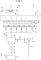
Fig. 1 is a diagram schematically illustrating a configuration of the liquid ejection apparatus of the first embodiment. - As illustrated in
Fig. 1 , aliquid ejection apparatus 1 includes aliquid ejection unit 20 that ejects ink (liquid) to a medium M, aliquid supply unit 30 that supplies the ink to theliquid ejection unit 20, and amaintenance unit 40 that performs maintenance of theliquid ejection unit 20. - The
liquid ejection unit 20 includes a plurality of (in the first embodiment, six)liquid ejection heads 22 in which a plurality ofnozzles 21 are formed, and asupport 23 that supports the plurality ofliquid ejection heads 22. In the first embodiment, the plurality ofnozzles 21 formed in theliquid ejection head 22 correspond to an example of a "nozzle group". In addition, the plurality ofliquid ejection heads 22 are arranged in parallel in a width direction (right-left direction inFig. 1 ) of the medium M, which intersects with a transport direction (inFig. 1 , a direction orthogonal to the paper surface) of the medium M. - Further, in
Fig. 1 , the drawing is simplified for convenience of description; however, when thenozzles 21 of each of theliquid ejection heads 22 are projected in the transport direction of the medium M, the projectednozzles 21 of each of theliquid ejection heads 22 are arranged side by side at a certain interval in the width direction of the medium M. - The
liquid supply unit 30 includes aliquid supply source 31 that stores ink which is supplied to theliquid ejection unit 20, asupply flow path 32 that connects theliquid supply source 31 with theliquid ejection unit 20, and apressurization pump 33 that is connected to theliquid supply source 31 and applies pressure to the ink stored in theliquid supply source 31 and supplies the ink to theliquid ejection unit 20. Theliquid supply source 31 may be a liquid cartridge which is detachably mounted in theliquid ejection apparatus 1 or may be a liquid containing tank provided in theliquid ejection apparatus 1. - Driving of the
pressurization pump 33 enables thesupply flow path 32 to supply the liquid to theliquid ejection unit 20 from theliquid supply source 31. - The
maintenance unit 40 includes acap 41 which causes a space including an opening of thenozzle 21 of theliquid ejection head 22 to be formed as a closed space CP (refer toFig. 5 ), abuffer tank 42 having a predetermined spatial volume which can store a fluid (including ink and gas) which is subjected to pressure reduction to a level lower than atmospheric pressure, an ink suction pump (suction unit) 45 and a pressure reducing pump (pressure reducing unit) 46 for reducing pressure of the space of thebuffer tank 42 and suctioning the ink from the closed space CP, and awaste liquid container 47 that is able to contain the fluid including the ink discharged from theink suction pump 45 and thepressure reducing pump 46. - In addition, the
maintenance unit 40 includes a plurality of branched flow paths (fluid discharge path) 43 of which one end is connected to each of thecap 41, a joining flow path (fluid discharge path) 44 which connects the other end of each of thebranched flow paths 43 with thebuffer tank 42, a first suction-side flow path 34 that connects thebuffer tank 42 and theink suction pump 45, a first discharge-side flow path 35 that connects theink suction pump 45 and thewaste liquid container 47, a second suction-side flow path 36 that connects thebuffer tank 42 and thepressure reducing pump 46, and a second discharge-side flow path (passage) 37 that connects thepressure reducing pump 46 and thewaste liquid container 47. - Further, the
maintenance unit 40 of the first embodiment includes a filter unit 10 for adsorbing volatile organic compounds contained in the ink discharged from theliquid ejection head 22. - The
cap 41 has a bottomed box shape and is relatively movable with respect to anozzle forming surface 24 of theliquid ejection head 22. Also, thecap 41 moves in an approaching direction to theliquid ejection head 22 and comes into contact with thenozzle forming surface 24, and thereby, the closed space CP is formed. In the first embodiment, in this manner, thecap 41 comes into contact with thenozzle forming surface 24 and forms the closed space CP, which is referred to as "capping". In addition, thecap 41 may be separated from thenozzle forming surface 24 and thereby the closed space CP is eliminated, which is referred to as "uncapping". - A plurality of CP-side on-off valves (on-off device) 51 which allow or regulate circulation of the ink in the branched
flow path 43 are provided on the branchedflow path 43. Therefore, when theliquid ejection head 22 is capped with thecap 41 and the CP-side on-offvalves 51 are opened, the closed space CP and thebuffer tank 42 enter into a communication state through the branchedflow path 43 and the joiningflow path 44. - Meanwhile, when the
liquid ejection head 22 is capped with thecap 41 and the CP-side on-offvalves 51 are closed, the closed space CP and thebuffer tank 42 enter into a non-communication state. When at least one of theink suction pump 45 and thepressure reducing pump 46 is driven in a state in which the entire plurality of CP-side on-offvalves 51 are closed, thebuffer tank 42 is subjected to pressure reduction to have a pressure (negative pressure) lower than atmospheric pressure. - In addition, the
liquid ejection head 22 is capped, and any CP-side on-offvalve 51 is opened in a state in which thebuffer tank 42 is subjected to pressure reduction to a level lower than atmospheric pressure. In this manner, any closed space CP communicating with thebuffer tank 42 is subjected to the rapid pressure reduction. - Since an opening/closing operation can be independently performed on the CP-side on-off
valves 51, a specific one of the CP-side on-offvalves 51 may be opened only, and thereby only a specific closed space CP corresponding to the opened CP-side on-offvalve 51 can enter into the communication state with thebuffer tank 42. - Further, without providing the joining
flow path 44, the other end of the branchedflow path 43 may be directly connected to thebuffer tank 42. - The
ink suction pump 45 is connected to thebuffer tank 42 through the first suction-side flow path 34 and reduces the pressure of thebuffer tank 42 through the first suction-side flow path 34. - The discharge side of the
ink suction pump 45 communicates with thewaste liquid container 47 through the first discharge-side flow path 35. A suction pump-side on-offvalve 54 is provided on the first discharge-side flow path 35. - The suction pump-side on-off
valve 54 functions to prevent suctioning from thewaste liquid container 47 which is constantly opened to the atmosphere and to reliably lower pressure only on thecap 41 side when thepressure reducing pump 46 performs suctioning from thebuffer tank 42. - The pressure reducing pump (pressure reducing unit) 46 is connected to the
buffer tank 42 through the second suction-side flow path 36 and reduces the pressure of thebuffer tank 42 through the second suction-side flow path 36. Thepressure reducing pump 46, due to a suction force thereof, suctions gas containing the volatile organic compounds vaporized from the ink in thebuffer tank 42. At this time, it is desirable that the ink is not suctioned. - The discharge side of the
pressure reducing pump 46 communicates with thewaste liquid container 47 through the second discharge-side flow path 37. - A
check valve 55 is disposed on the second suction-side flow path 36. Thecheck valve 55 allows only gas to flow toward thepressure reducing pump 46 side from thebuffer tank 42 and prevents the reverse flow of the gas toward thebuffer tank 42 side from thepressure reducing pump 46. - Here, it is desirable that the amount of pressure reduction of the
ink suction pump 45 is greater than the amount of pressure reduction of thepressure reducing pump 46. As an example, theink suction pump 45 is a tube pump and thepressure reducing pump 46 is a diaphragm pump, and thereby the amount of pressure reduction of theink suction pump 45 may become greater than the amount of pressure reduction of thepressure reducing pump 46. - In addition, it is desirable that the
ink suction pump 45 has a pressure reduction speed higher than thepressure reducing pump 46. - An atmosphere
open path 56, through which the inside of thewaste liquid container 47 is opened to the atmosphere, is provided to thewaste liquid container 47. The atmosphereopen path 56 is in a state in which thewaste liquid container 47 constantly communicates with the air. - The
maintenance unit 40 according to the first embodiment further includes the filter unit 10 for adsorbing the volatile organic compounds contained in the ink discharged from theliquid ejection head 22. - The filter unit 10 has a
first filter 11 disposed on the ink inflow side of thepressure reducing pump 46, a second filter 12 disposed on the ink discharge side of thepressure reducing pump 46, and a third filter 13 disposed on the atmosphere open side of thewaste liquid container 47. The respective filters 11, 12, and 13 are filtering media which filter not only liquids but also gases. In the first embodiment, an activated carbon filter is used; however, there is no limitation on the material of the filter. - The
first filter 11 is disposed on the second suction-side flow path 36 and collects the volatile organic compounds in the ink flowing out from thebuffer tank 42 due to a suction force of thepressure reducing pump 46. - The second filter 12 is disposed on the second discharge-
side flow path 37 and collects the volatile organic compounds which are not collected in thefirst filter 11 and remains in the ink discharged from thepressure reducing pump 46. - The third filter 13 is disposed on the atmosphere
open path 56 connected to thewaste liquid container 47 and collects the volatile organic compounds existing in thewaste liquid container 47. Here, the volatile organic compounds contained in the ink discharged from theink suction pump 45 or the volatile organic compounds vaporized from the ink stored in thewaste liquid container 47 are included. The third filter 13 performs final collection such that collection efficiency of the volatile organic compounds which are discharged to the outside from themaintenance unit 40 is improved, and thus an elimination performance of the volatile organic compounds is improved. - After gas passes through the third filter 13, the gas has a small amount of the remaining volatile organic compounds. Therefore, the
first filter 11 and the second filter 12 lower a collection load, and thus the filters function as the filter for a long period of time. - Next, a configuration of the
liquid ejection head 22 will be described in detail with reference toFig. 2 and Fig. 3 . -
Fig. 2 is a diagram schematically illustrating a configuration of the liquid ejection head.Fig. 3 is a diagram schematically illustrating a configuration related to liquid ejection of the liquid ejection head. Further,Fig. 3 is a view schematically illustrating a sectional plane of theliquid ejection head 22, which intersects with a nozzle array direction (in right-left direction inFig. 2 ) of theliquid ejection head 22 illustrated inFig. 2 . - As illustrated in
Fig. 2 and Fig. 3 , theliquid ejection head 22 includes acommon liquid chamber 25 that stores ink supplied through thesupply flow path 32, theliquid chamber 26 having a changeable volume, anactuator 27 driven when ink is ejected from thenozzle 21, and anaccommodation chamber 28 that accommodates theactuator 27, as well as the plurality ofnozzles 21. Thecommon liquid chamber 25 is commonly provided for the plurality ofnozzles 21, while a plurality of theliquid chambers 26, a plurality of theaccommodation chambers 28, and a plurality of theactuators 27 are provided, with one of the plurality of theliquid chambers 26, one of the plurality of theaccommodation chambers 28 and one of the plurality of theactuators 27 being provided respectively for eachsingle nozzle 21. - As illustrated in
Fig. 3 , thecommon liquid chamber 25 along with theaccommodation chamber 28, and theliquid chamber 26 are partitioned by an elasticallydeformable vibration plate 29. In addition, thecommon liquid chamber 25 and theliquid chamber 26 communicate with each other through acommunication hole 29a formed in thevibration plate 29. Therefore, the ink supplied from theliquid supply source 31 through thesupply flow path 32 is temporarily stored in thecommon liquid chamber 25, and then the ink is supplied to eachnozzle 21 through thecommunication hole 29a and theliquid chamber 26 fromcommon liquid chamber 25. For example, theactuator 27 is a piezoelectric element which is contracted in a case where a drive voltage is applied. Therefore, when the drive voltage applied to theactuator 27 is changed, thevibration plate 29 is deformed as illustrated by a two-dot chain line inFig. 3 , the volume of theliquid chamber 26 is changed, and thereby the ink in theliquid chamber 26 is ejected as a droplet from thenozzle 21. - Next, an electrical configuration of a
control unit 60 which is provided in theliquid ejection apparatus 1 will be described with reference toFig. 4 . - As illustrated in
Fig. 4 , theactuator 27 and apressure sensor 52 are connected to an input-side interface of thecontrol unit 60. In comparison, theliquid ejection head 22, theactuator 27, thepressurization pump 33, thecap 41, theink suction pump 45, thepressure reducing pump 46, the CP-side on-offvalve 51, and the suction pump-side on-offvalve 54 are connected to an output-side interface of thecontrol unit 60. Also, thecontrol unit 60 causes the respective configurations connected to the output-side interface to operate in response to an output signal from theactuator 27 and thepressure sensor 52, and thereby the control unit performs maintenance of eliminating an ejection defect in theliquid ejection head 22. - Next, an outline of the maintenance of the
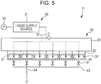
liquid ejection apparatus 1 and a relationship between a discharge amount and a supply amount of a liquid in the same maintenance will be described with reference toFig. 1 andFig. 5 . -
Fig. 5 is a diagram schematically illustrating a partial configuration of the liquid ejection apparatus during the maintenance. - In the first embodiment, in a case where there is a defective nozzle to which a foreign object such as a bubble is mixed in the
nozzle 21 of theliquid ejection head 22, or the like, in order to eliminate ejection defect of such a defective nozzle, the maintenance of discharging a foreign object such as a bubble along with discharging the ink from thenozzle 21 of theliquid ejection head 22 is performed. To be more specific, as illustrated inFig. 5 , theliquid ejection head 22 as a target of the maintenance is capped such that the closed space CP is formed, and the closed space CP is subjected to pressure reduction such that the foreign object such as a bubble is discharged along with the ink from thenozzle 21 of theliquid ejection head 22. - First, as illustrated in
Fig. 1 , thepressure reducing pump 46 of themaintenance unit 40 is driven in a state in which theliquid ejection head 22 is capped and the inside of thebuffer tank 42 is subjected to the rapid pressure reduction. In a state in which thebuffer tank 42 is subjected to pressure reduction to have pressure lower than atmospheric pressure, any one of the CP-side on-offvalves 51 is opened, and thereby any closed space CP communicating with thebuffer tank 42 is subjected to the rapid pressure reduction. In this manner, the inside of thebuffer tank 42 is subjected to pressure reduction such that negative pressure is accumulated therein, and thereby negative pressure is rapidly applied to the inside of thecap 41 such that ink containing bubbles, a foreign object, or the like is discharged from thenozzle 21 of theliquid ejection head 22. The ink discharged into thecap 41 flows into thebuffer tank 42 having a reduced pressure through the branchedflow path 43 and the joiningflow path 44. Therefore, the volatile organic compounds exist in thebuffer tank 42. - Subsequently, the driving of the
pressure reducing pump 46 is continuously performed such that gas containing volatile organic compounds in thebuffer tank 42 is suctioned. When the gas flowing out from thebuffer tank 42 due to the suction force of thepressure reducing pump 46 passes through thefirst filter 11 provided in the second suction-side flow path 36, the volatile organic compounds contained in the gas are collected in thefirst filter 11. The volatile organic compounds remaining in the gas discharged from thepressure reducing pump 46 are collected in the second filter 12 provided in the second discharge-side flow path 37. Emission of gas containing volatile organic compounds from thebuffer tank 42 is actively performed by thepressure reducing pump 46, and thereby the volatile organic compounds are collected in thefirst filter 11 and the second filter 12. - Gas, from which the volatile organic compounds are removed, flows to the
waste liquid container 47 through the second discharge-side flow path 37. - Next, the suction pump-side on-off
valve 54 is opened such that theink suction pump 45 is driven and waste ink removed from the inside of thebuffer tank 42 is discharged to thewaste liquid container 47. The driving of theink suction pump 45 is stopped, and then the reverse flow of the ink in the first suction-side flow path 34 is prevented by opening the suction pump-side on-offvalve 54. - The inside of the
waste liquid container 47 is opened to the atmosphere through the atmosphere open path. At this time, in the third filter 13 provided in the atmosphereopen path 56, final collection of the volatile organic compounds contained in the gas in thewaste liquid container 47, which is released to the atmosphere, is performed. - Since the ink which discharges the volatile organic compounds is stored in the
waste liquid container 47, the third filter 13 is provided in the atmosphereopen path 56 and the gas containing the volatile organic compounds is filtered through the third filter 13 and is exhausted. - According to the
liquid ejection apparatus 1 of the first embodiment, it is possible to significantly reduce the content of the volatile organic compounds in the gas exhausted from themaintenance unit 40. The plurality offilters 11, 12, and 13 are disposed on a flow route of the gas containing the volatile organic compounds, and thereby it is possible to efficiently collect the volatile organic compounds. - In fulfillment of the maintenance (cleaning operation) of the
liquid ejection head 22, the inside of thebuffer tank 42 is subjected to pressure reduction by thepressure reducing pump 46 such that the negative pressure is accumulated therein, and thereby the negative pressure is rapidly applied to the inside of thecap 41 such that the ink is discharged from theliquid ejection head 22. In this case, the emission of the gas containing the volatile organic compounds from thebuffer tank 42, into which a large amount of ink flows, is likely to be actively performed. According to this configuration, the plurality offilters 11, 12, and 13 provided on the downstream side from thebuffer tank 42 enable effective removal of the volatile organic compounds contained in the gas discharged from thebuffer tank 42. - Hence, since it is possible to sufficiently reduce the volatile organic compounds contained in the exhaust gas even in a printer which has a high printing speed as of a line head and is likely to generate a large amount of volatile organic compounds, it is possible to satisfy a regulation of a discharge amount of the volatile organic compounds, which is regulated with a discharge amount within a predetermined period of time.
- In addition, the filter unit 10 is provided in the
maintenance unit 40, and thereby it is possible to collect the volatile organic compounds in a tightly closed space. Themaintenance unit 40 according to the first embodiment is configured to have high airtightness. Since a fluid (ink and gas containing volatile organic compounds which are volatilized) is contained in themaintenance unit 40 in a state of a relatively high airtightness, the filter unit 10 is provided in themaintenance unit 40, and thereby it is possible to significantly reduce an amount of the volatile organic compounds discharged from themaintenance unit 40 to the outside. - In addition, since the ink is contained in the
maintenance unit 40 completely in a liquid state, it is possible to suppress volatilization of the volatile organic compounds contained in the ink. Accordingly, it is possible to reduce the volatile organic compounds discharged to the outside of themaintenance unit 40 and theliquid ejection apparatus 1. - Further, in the first embodiment, both the discharge sides of the
ink suction pump 45 and thepressure reducing pump 46 are connected to thewaste liquid container 47. Therefore, it is possible to contain, completely in the liquid state, the ink containing the volatile organic compounds in thewaste liquid container 47. Hence, it is possible to suppress volatilization of the volatile organic compounds contained in the ink. - Further, the filter unit 10 of the first embodiment is configured to include three
filters 11, 12, and 13; however, the number or positions of the filters are not limited thereto. - For example, in the first embodiment, the
filters 11 and 12 are disposed at both the suction side and the discharge side of thepressure reducing pump 46; however, the filters may be disposed on any one side. In addition, a configuration in which the filter 13 is provided only in the atmosphereopen path 56, without providing thefilters 11 and 12 on thepressure reducing pump 46 side, may for example be provided. - The
filter 11 provided on the suction side of thepressure reducing pump 46 enables reliable collection of the volatile organic compounds from thebuffer tank 42 in which a large amount of the ink flows, and thereby a large amount of the volatile organic compounds is likely to be accumulated. In addition, even in a case where the filter 12 is provided on the discharge side of thepressure reducing pump 46 without providing thefilter 11 on the suction side of thepressure reducing pump 46, similar effects to the above mentioned ones are obtained and it is possible to also collect volatile organic compounds which can be generated from thepressure reducing pump 46 itself. The positions and the number of the filters can be appropriately determined depending on a circumstance such as a size of a filter, collection performance of a filter, space in theliquid ejection apparatus 1, or the like. In addition, in a case where the filter 13 is provided only in the atmosphereopen path 56, it is possible to completely collect the volatile organic compounds contained in the ink discharged from theink suction pump 45 at only one position, the volatile organic compounds discharged from thepressure reducing pump 46, or the volatile organic compounds vaporized from the ink stored in thewaste liquid container 47 and it is possible to efficiently reduce the volatile organic compounds from theentire maintenance unit 40. - In addition, in the configuration of the first embodiment, since the downstream side of the
pressure reducing pump 46 is connected to thewaste liquid container 47 through the second discharge-side flow path 37, it is possible to store the ink in thewaste liquid container 47 and to suppress leakage to the outside (in the apparatus) even in a case where the ink flows around thepressure reducing pump 46. - Next, Modification Example 1 (also being an embodiment of the present invention) of the filter unit and a peripheral structure thereof will be described.
-
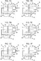
Figs. 6A to 6F are views illustrating the filter unit and the peripheral structure thereof according to Modification Example 1. - As illustrated in
Fig. 6A , according to modification example 1, afilter unit 14 is provided between thebuffer tank 42 and a pair ofpressure reducing pumps - A
first selection mechanism 63 which selects an inlet-side flow path in thefilter unit 14 is provided on the upstream side of thefilter unit 14 and asecond selection mechanism 64 which selects an outlet-side flow path in thefilter unit 14 is provided on the downstream side of thefilter unit 14. - The
filter unit 14 is configured to include afilter accommodating section 15 which has aninflow chamber 15a and twofiltration chambers filter 11 disposed in thefilter accommodating section 15. Thefilter 11 is disposed between the inflow chamber and two filtration chambers such that theinflow chamber 15a is separated from twofiltration chambers respective filtration chambers inflow chamber 15a through thefilter 11. - The second suction-
side flow path 36 extending from thebuffer tank 42 is branched into two flow paths at an intermediate position and is connected to thefilter accommodating section 15 through a first branched flow path (inlet flow path) 36A and a second branched flow path (inlet flow path) 36B. The firstbranched flow path 36A is connected to theinflow chamber 15a of thefilter accommodating section 15 and the secondbranched flow path 36B is connected to thefiltration chamber 15c on one side. Thefirst filtration chamber 15b of thefilter accommodating section 15 is connected to the firstpressure reducing pump 46A through a flow path (outlet flow path) 36C and thesecond filtration chamber 15c is connected to the secondpressure reducing pump 46B through a flow path (outlet flow path) 36D. - The
first selection mechanism 63 is configured to include the firstbranched flow path 36A, the secondbranched flow path 36B, a first on-offvalve 55A provided in the firstbranched flow path 36A, and a second on-offvalve 55B provided in the secondbranched flow path 36B. - The
second selection mechanism 64 is configured to include the firstpressure reducing pump 46A, the secondpressure reducing pump 46B, aflow path 36C that connects thefilter unit 14 with the firstpressure reducing pump 46A, and theflow path 36D that connects thefilter unit 14 with the secondpressure reducing pump 46B. - In the Modification Example 1, a combination of the inlet flow path and the outlet flow path which are selected in the
first selection mechanism 63 and thesecond selection mechanism 64 enables selection of whether the gas suctioned from thebuffer tank 42 passes or does not pass through thefilter 11. In other words, an opening/closing operation of the on-offvalves pressure reducing pumps - Next, Modification Example 2 (also being an embodiment of the present invention) of the filter unit and a peripheral structure thereof will be described.
-
Figs. 7A to 7E are views illustrating the filter unit and the peripheral structure thereof according to Modification Example 2. - As illustrated in
Fig. 7A , according to Modification Example 2, afilter unit 14 is provided between thebuffer tank 42 and onepressure reducing pump 46. Here, on-offvalves filter unit 14 and thepressure reducing pump 46, the opening/closing control is performed, and thereby a suction operation can be performed using onepressure reducing pump 46. - Since the
first selection mechanism 63 disposed on the upstream side of thefilter unit 14 is the same as that in Modification Example 1, description thereof is omitted. - The
second selection mechanism 65 disposed on the downstream side of thefilter unit 14 is configured to include theflow paths filter unit 14 and thepressure reducing pump 46, the on-offvalves flow paths pressure reducing pump 46. - Also, in the Modification Example 2, a combination of the inlet flow path and the outlet flow path which are selected in the
first selection mechanism 63 and thesecond selection mechanism 65 enables selection of whether the gas suctioned from thebuffer tank 42 passes or does not pass through thefilter 11. In other words, an opening/closing operation of the on-offvalves - The
filter unit 14 according to respective Modification Examples 1 and 2 has a first flow path passing through thefilter 11 and a second flow path without passing through thefilter 11. The second flow path without passing through thefilter 11 is a route of flowing directly to thesecond filtration chamber 15c of thefilter accommodating section 15 from thebuffer tank 42 and discharging, as it is, to thewaste liquid container 47 due to the suction force of thepressure reducing pump 46. Since the gas flowing to theinflow chamber 15a of thefilter accommodating section 15 from thebuffer tank 42 needs to pass through thefilter 11, the gas is discharged through the first flow path according to the invention. In a case of a route in which gas flowing to thesecond filtration chamber 15c reversely flows to theinflow chamber 15a, the gas needs to pass through thefilter 11. Therefore, the route becomes the first flow path. - Next, the suction operation according to Modification Examples 1 and 2 will be described.
- According to Modification Example 1, as illustrated in
Fig. 6A , when the first on-offvalve 55A provided in the firstbranched flow path 36A is opened such that the firstpressure reducing pump 46A is driven, the gas flowing out from thebuffer tank 42 flows to theinflow chamber 15a of thefilter accommodating section 15 through the second suction-side flow path 36 and the firstbranched flow path 36A. The gas flowing to theinflow chamber 15a flows to thefirst filtration chamber 15b through thefilter 11 due to the suction force of the firstpressure reducing pump 46A. A filtering function of thefilter 11 causes the gas having a reduced content of the volatile organic compounds to be discharged toward thewaste liquid container 47 side from thepressure reducing pump 46A through theflow path 36C. - According to Modification Example 2, as shown in
Fig. 7A , when the first on-offvalve 55A provided in the firstbranched flow path 36A and the third on-offvalve 55C provided in theflow path 36C are opened to drive thepressure reducing pump 46, the gas flowing out from thebuffer tank 42 flows to theinflow chamber 15a of thefilter accommodating section 15 through the second suction-side flow path 36 and the firstbranched flow path 36A. The gas flowing to theinflow chamber 15a flows to thefirst filtration chamber 15b through thefilter 11 due to the suction force of thepressure reducing pump 46. The filtering function of thefilter 11 causes the gas having a reduced content of the volatile organic compounds to be discharged toward thewaste liquid container 47 side from thepressure reducing pump 46 through theflow path 36C. - In the suction operation, in any configuration, the gas passes the first flow path according to an embodiment of the invention and volatile organic compounds contained in the air is collected in a
first region 11A of thefilter 11. - According to Modification Example 1, as illustrated in
Fig. 6B , the first on-offvalve 55A is opened to drive the secondpressure reducing pump 46B. The gas flowing out from thebuffer tank 42 flows to theinflow chamber 15a of thefilter accommodating section 15 through the second suction-side flow path 36 and the firstbranched flow path 36A and flows out to thesecond filtration chamber 15c through asecond region 11B of thefilter 11 due to the suction force of the secondpressure reducing pump 46B. The gas having a reduced content of the volatile organic compounds by thefilter 11 is discharged toward thewaste liquid container 47 side from the firstpressure reducing pump 46A through theflow path 36D. - According to Modification Example 2, as illustrated in
Fig. 7B , when the first on-offvalve 55A and the fourth on-offvalve 55D are opened to drive thepressure reducing pump 46, the gas from thebuffer tank 42 passes through thesecond region 11B and flows to thesecond filtration chamber 15c. - In the suction operation, in all of the configurations, the gas passes through the first flow path according to an embodiment of the invention and the volatile organic compounds contained in the gas is removed in the
second region 11B of thefilter 11. - According to Modification Example 1, as illustrated in
Fig. 6C , when the first on-offvalve 55A is opened to drive both the firstpressure reducing pump 46A and the secondpressure reducing pump 46B, the gas from thebuffer tank 42 passes through the entire regions (thefirst region 11A and thesecond region 11B) of thefilter 11 and flows to thefirst filtration chamber 15b and thesecond filtration chamber 15c. - According to Modification Example 2, as illustrated in
Fig. 7C , when the first on-offvalve 55A on the upstream side and the two on-offvalves pressure reducing pump 46, the gas from thebuffer tank 42 passes through the entire region (thefirst region 11A and thesecond region 11B) of thefilter 11 and flows to thefirst filtration chamber 15b and thesecond filtration chamber 15c. - In the suction operation, in all of the configurations, the gas passes through the first flow path according to an embodiment of the invention and it is possible to filter the volatile organic compounds contained in the gas using the entire region of the
filter 11. Fourth Suction Operation - According to Modification Example 1, as illustrated in
Fig. 6D , the second on-offvalve 55B is opened to drive the firstpressure reducing pump 46A. - According to Modification Example 2, as illustrated in
Fig. 7D , the second on-offvalve 55B and the third on-offvalve 55C are opened to drive thepressure reducing pump 46. - Then, in all of the configurations, first, the gas in the
buffer tank 42 flows to thesecond filtration chamber 15c of thefilter accommodating section 15 through the second suction-side flow path 36 and the secondbranched flow path 36B. The gas flowing to thesecond filtration chamber 15c passes through thesecond region 11B of thefilter 11, flows to theinflow chamber 15a, then passes through thefirst region 11A of thefilter 11, and flows to thefirst filtration chamber 15b, due to the suction force of the firstpressure reducing pump 46A or thepressure reducing pump 46. - In the suction operation, the gas containing the volatile organic compounds passes through the
filter 11 twice. The number of times the gas passes through thefilter 11 is increased, and thereby it is possible to improve collection efficiency of the volatile organic compounds in the gas even using onefilter 11. In this manner, also in the suction operation, the gas passes through the first flow path according to an embodiment of the invention. - According to Modification Example 1, as illustrated in
Fig. 6E , the second on-offvalve 55B is opened to drive both the firstpressure reducing pump 46A and the secondpressure reducing pump 46B. - According to Modification Example 2, as illustrated in
Fig. 7E , the second on-offvalve 55B, the third on-offvalve 55C, the fourth on-offvalve 55D are opened to drive thepressure reducing pump 46. - Then, in all of the configurations, only a part of the gas passes through the
filter 11 twice (first flow path) and the rest of the gas is discharged without passing through the filter 11 (second flow path). - In this manner, only a part of the gas may be filtered the second time and the rest of the gas may be discharged without being filtered. The remaining volatile organic compounds without being filtered in the
filter unit 14 are removed in the filter provided in the atmosphere open path. - According to Modification Example 1, as illustrated in
Fig. 6F , the second on-offvalve 55B is opened to drive the secondpressure reducing pump 46B. - According to Modification Example 2, as illustrated in
Fig. 7F , the fourth on-offvalve 55D is opened to drive thepressure reducing pump 46. - In such an operation, it is possible to discharge the gas without passing through the filter 11 (second flow path).
- As described above, according to the configurations of Modification Examples 1 and 2, in a configuration of the
filter unit 14 and the periphery thereof, a flow path in which thefilter 11 exists and a flow path in which thefilter 11 does not exist are provided and driving of the pressure reducing pump or the like is controlled. In this manner, it is possible to select any one flow path through which the gas flows. - For example, only during a cleaning operation related to the volatile organic compounds, the gas in the
buffer tank 42 passes through thefilter 11. In a case except for the cleaning operation, the gas does not pass through thefilter 11, or the like, and it is possible to appropriately select a flow path depending on an amount of the volatile organic compounds contained in the gas and a usage state of thefilter 11. - The number of times the gas passes through the
filter 11 is appropriately selected depending on concentration of the volatile organic compounds, and thereby high collection efficiency is achieved and it is possible to further reduce the amount of the volatile organic compounds discharged to the outside. In addition, in a case except for the cleaning operation, the gas does not pass through thefilter 11, and thereby the service life of thefilter 11 can be extended. - In addition, even if clogging or the like occurs in the
filter 11, it is possible to suction the gas from thebuffer tank 42 without losing a flow rate and to perform pressure reduction. The gas which has passed through thefilter unit 14 is filtered in thefilter 11 provided on the discharge side of the secondpressure reducing pump 46B or thepressure reducing pump 46, and the volatile organic compounds are removed. - Next, a second embodiment of the invention will be described.
-
Fig. 8 is a diagram schematically illustrating the entire configuration of the liquid ejection apparatus of the second embodiment. - A basic configuration of the liquid ejection apparatus of the second embodiment to be described below is substantially the same as that of the first embodiment; however, a configuration of the maintenance unit is different. Hence, in the following description, the configuration of the maintenance unit will be described in detail and description of the common parts is omitted. In addition, in the respective drawings referred to in the description, the same reference sign is assigned to the same component which is common in
Fig. 1 to Fig. 5 . - The liquid ejection apparatus according to the second embodiment includes a
maintenance unit 61 which mainly has thebuffer tank 42, thepressure reducing pump 46, theink suction pump 45, thewaste liquid container 47, and the filter unit 10. The configuration is different from that of the first embodiment in that the downstream side of thepressure reducing pump 46 is not connected to thewaste liquid container 47. In the second embodiment, an atmosphereopen path 57 is connected to the downstream side of thepressure reducing pump 46 and constant atmospheric release is performed. - The second filter 12 of the filter unit 10 is disposed in the atmosphere
open path 57. Since the volatile organic compounds, which is not removed in thefirst filter 11 and remains, is collected in the second filter 12, an amount of the volatile organic compounds contained in the gas which is released to the atmosphere is small. - Next, a third embodiment of the invention will be described.
-
Fig. 9 is a diagram schematically illustrating an entire configuration of a liquid ejection apparatus of the third embodiment. - A basic configuration of the liquid ejection apparatus of the third embodiment to be described below is substantially the same as that of the first embodiment; however, a configuration of the maintenance unit is different. Hence, in the following description, the configuration of the maintenance unit will be described in detail and description of the common parts is omitted. In addition, in the respective drawings referred to in the description, the same reference sign is assigned to the same component which is common in
Fig. 1 to Fig. 5 . - The liquid ejection apparatus according to the third embodiment includes a
maintenance unit 62 which mainly has thebuffer tank 42, theink suction pump 45, thewaste liquid container 47, and the filter unit 10. The configuration is different from that of the above embodiments in that themaintenance unit 62 does not include thepressure reducing pump 46. - In the third embodiment, since the
pressure reducing pump 46 is not provided, theink suction pump 45 performs the pressure reduction in thebuffer tank 42 during the maintenance. - The inside of the
buffer tank 42 is subjected to the pressure reduction due to the suction force of theink suction pump 45. Any CP-side on-offvalve 51 is opened, the inside of thecap 41 has negative pressure, and thereby ink is suctioned from the nozzle. The ink and a foreign object such as a bubble discharged to the inside of thecap 41 flow to the inside of thebuffer tank 42 and are discharged to thewaste liquid container 47 due to the suction force of theink suction pump 45. An operation of theink suction pump 45 is stopped, then the suction pump-side on-offvalve 54 is opened, and reverse flow of the ink or the like from thewaste liquid container 47, which is opened to the atmosphere, is prevented. At this time, the volatile organic compounds contained in the gas released from thewaste liquid container 47 are collected in the third filter 13 provided in the atmosphereopen path 56. In other words, the volatile organic compounds vaporized from the ink in thebuffer tank 42 and thewaste liquid container 47 are collected in the third filter 13, and thereby it is possible to reduce the volatile organic compounds which are released to the outside. - In a case of the third embodiment, since the filter unit 10 includes only the third filter 13, it is preferable that a filter having high collection performance of the volatile organic compounds is used as the third filter 13. In addition, a plurality of filters may be disposed on the atmosphere
open path 56. Alternatively, or in addition, a filter may be disposed on a flow path from thecap 41 to thewaste liquid container 47. - As described above, in the maintenance unit of the liquid ejection apparatus of the embodiments, one or a plurality of filters are provided in a tightly closed space, that is, on a discharge flow path from the
cap 41, the gas containing the volatile organic compounds is caused to pass through a filter and then to be discharged to the outside, and thereby it is possible to simply and effectively collect the volatile organic compounds contained in the gas. Hence, it is possible to reduce the volatile organic compounds which are discharged to the outside (e.g. to the outside of the maintenance unit). - In addition, a VOC adsorbing filter that adsorbs the volatile organic compounds is further provided in a fan installation portion provided in a main body of the
liquid ejection apparatus 1 and may be able to collect the volatile organic compounds which it is not possible to collect in the maintenance unit. In a case where the VOC adsorbing filter is provided, it is preferable that the atmosphere open side of thewaste liquid container 47 and the discharge side of thepressure reducing pump 46 are opened toward the fan installation portion (adsorption filter) side. - In addition, in a case where the VOC adsorbing filter is not provided in the fan installation portion, it is preferable that the atmosphere open side of the
waste liquid container 47 and the discharge side of thepressure reducing pump 46 are opened in a separating direction from the fan installation portion. Since the specific gravity of the volatile organic compounds is greater than water in many cases, it is preferable that the atmosphere open side of thewaste liquid container 47 and the discharge side of thepressure reducing pump 46 are positioned below the fan installation portion. Otherwise, it is preferable that the atmosphere open side of thewaste liquid container 47 and the discharge side of thepressure reducing pump 46 are opened toward the lower side of a housing of theliquid ejection apparatus 1. - In this manner, since the volatile organic compounds discharged from the maintenance unit are accumulated in the housing, it is possible to suppress an amount to be discharged to the outside.
- As above, preferable embodiments according to the invention are described with reference to the accompanying drawings; however, it is needless to say that the invention is not limited to an example. Those skilled in the art may conceive of various examples of modifications or alterations within the scope of the invention and it is to be understood that the various examples belong to the technical scope of the invention. An appropriate combination of the configurations of the embodiments may be performed.
- According to the second embodiment, a configuration in which the
filters 11 and 12 are on both the suction side and the discharge side of thepressure reducing pump 46 is employed; however, the filters may be disposed on either one of those sides only. - In addition, a configuration in which the filter 13 of the atmosphere
open path 56 is omitted may be provided. - In the liquid ejection apparatus, there is a concern that so-called mist will be generated with a part of the ink scattered around like fog at the time of discharging of the ink, and thereby a recording medium to which the ink is discharged or a surface of a transport stage which transports the recording medium will be stained.
- Therefore, a configuration, in which a mechanism that collects such mist is provided in the liquid ejection apparatus, may be employed.
-
Fig. 10 is a diagram illustrating a configurational example, also being an embodiment of the present invention, in which a mist collecting unit is included. - For example, as illustrated in
Fig. 10 , a configuration, in which a mist collecting unit (collecting unit) 71 that collectsmist 17a existing in the apparatus is provided, may be employed. The downstream side of themist collecting unit 71 is connected finally to thewaste liquid container 47 and the collectedmist 17a is contained in thewaste liquid container 47 with waste ink. The volatile organic compounds contained in themist 17a are collected in therespective filters 11, 12, and 13 of the filter unit 10. - In this manner, the
mist 17a floating in the housing of the liquid ejection apparatus is collected, and thereby not only it is possible to prevent a stain on the recording medium and in the apparatus due to themist 17a, but also it is possible to collect the volatile organic compounds contained in themist 17a in the filter unit 10. Therefore, it is possible to reduce an amount of the volatile organic compounds which is discharged to the outside of the apparatus. - Further, the configuration, in which the
mist collecting unit 71 is provided, can be used in any one of the respective embodiments described above. - In the above embodiments, the configuration, in which any buffer tank is included, is employed; however, a configuration, in which no buffer tank is included, may be employed.
-
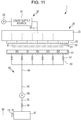
Fig. 11 is a diagram illustrating a configurational example, also being an embodiment of the present invention, in which no buffer tank is included. - For example, as illustrated in
Fig. 11 , without the buffer tank, an end portion on the downstream side of the branchedflow path 43 connected to eachcap 41 may be connected to the first suction-side flow path 34. The closed space CP of anycap 41 may be directly subjected to the pressure reduction by theink suction pump 45, and thereby ink containing bubbles or foreign objects from thenozzle 21 of theliquid ejection head 22 is discharged to thecap 41. The ink discharged in thecap 41 flows to thewaste liquid container 47 through the branchedflow path 43, the first suction-side flow path 34 and the first discharge-side flow path 35. - In addition, it is possible to appropriately change the number, position, or the like, of the filters. If at least one filter is disposed at any position of the maintenance unit, it is possible to reduce the volatile organic compounds which are discharged to the outside as compared with prior art. At this time, a filter is provided on the atmosphere open side of the maintenance unit, and thereby it is possible to efficiently perform collection in the filter, without the volatile organic compounds remaining in the maintenance unit.
- The foregoing description has been given by way of example only and it will be appreciated by a person skilled in the art that modifications can be made without departing from the scope of the present invention as defined by the claims.
Claims (7)
- A liquid ejection apparatus (1) comprising:a liquid ejection head (22) having a nozzle (21) which ejects a liquid containing volatile organic compounds to a medium (M); anda maintenance unit (40) that has a cap (41), which forms a closed space (CP) including an opening of the nozzle, and a suction unit (45) that suctions a fluid from the closed space, and that performs maintenance for discharging the liquid from the nozzle by reducing pressure of the closed space,wherein the maintenance unit is provided with a filter (13, 10) for adsorbing volatile organic compounds contained in the liquid discharged from the liquid ejection head,wherein the maintenance unit has a waste liquid container (47) which is able to contain the fluid suctioned from the closed space,wherein the filter is provided on a side of the waste liquid container open to atmosphere,wherein the maintenance unit further includesa fluid discharge path (43) that connects the cap with the suction unit,an on-off device (51) that opens and closes the fluid discharge path, anda buffer tank (42) that forms a part of the fluid discharge path on the downstream side of the on-off device and that has a predetermined spatial volume, andwherein the buffer tank communicates with the waste liquid container through the suction unit.
- A liquid ejection apparatus (1) comprising:a liquid ejection head (22) having a nozzle (21) which ejects a liquid containing volatile organic compounds to a medium (M); anda maintenance unit (40) that has a cap (41), which forms a closed space (CP) including an opening of the nozzle, and a suction unit (45) that suctions a fluid from the closed space, and that performs maintenance for discharging the liquid from the nozzle by reducing pressure of the closed space,wherein the maintenance unit is provided with a filter (11, 10; 12, 10; 13, 10) for adsorbing volatile organic compounds contained in the liquid discharged from the liquid ejection head,wherein the maintenance unit further includesa fluid discharge path (43) that connects the cap with the suction unit,an on-off device (51) that opens and closes the fluid discharge path,a buffer tank (42) that forms a part of the fluid discharge path on the downstream side of the on-off device and that has a predetermined spatial volume, anda pressure reducing unit (46) that is connected to the buffer tank and reduces pressure of a space of the buffer tank, andwherein the filter (11, 10; 12, 10; 13, 10) is provided on at least one of an upstream side and a downstream side of the pressure reducing unit.
- The liquid ejection apparatus according to Claim 2,
wherein the maintenance unit has a waste liquid container (47) which is able to contain the fluid suctioned from the closed space, and
wherein the discharge side of the pressure reducing unit communicates with the waste liquid container through a passage (37). - The liquid ejection apparatus according to Claim 2 or 3,
wherein the filter (12, 10) is provided on the downstream side of the pressure reducing unit. - The liquid ejection apparatus according to Claim 3,
wherein the filter (13, 10) is provided on a side of the waste liquid container open to atmosphere. - The liquid ejection apparatus according to any one of the preceding claims,
wherein the maintenance unit is provided with a first flow path, which passes through the filter, and a second flow path, which does not pass through the filter,
wherein a first on-off valve, which is openable and closable of the first flow path, is provided on an inlet side of the first flow path, and
wherein a second on-off valve, which is openable and closable of the second flow path, is provided on an inlet side of the second flow path, and combinations of opening and closing operations of the first on-off valve and the second on-off valve enable selection of a flow path through which the fluid passes. - The liquid ejection apparatus according to any of Claims 1, 3, or according to claim 4, 5, 6 as dependent directly or indirectly upon claim 3, further comprising; a mist collecting unit (71) that collects mist generated when the liquid is ejected from the liquid ejection head,
wherein a discharge side of the mist collecting unit is connected with the waste liquid container.
Applications Claiming Priority (1)
| Application Number | Priority Date | Filing Date | Title |
|---|---|---|---|
| JP2015050509A JP6520247B2 (en) | 2015-03-13 | 2015-03-13 | Liquid injection device |
Publications (2)
| Publication Number | Publication Date |
|---|---|
| EP3067207A1 EP3067207A1 (en) | 2016-09-14 |
| EP3067207B1 true EP3067207B1 (en) | 2019-02-27 |
Family
ID=55168200
Family Applications (1)
| Application Number | Title | Priority Date | Filing Date |
|---|---|---|---|
| EP16151535.8A Active EP3067207B1 (en) | 2015-03-13 | 2016-01-15 | Liquid ejection apparatus |
Country Status (4)
| Country | Link |
|---|---|
| US (1) | US9724923B2 (en) |
| EP (1) | EP3067207B1 (en) |
| JP (1) | JP6520247B2 (en) |
| CN (1) | CN105966071B (en) |
Families Citing this family (5)
| Publication number | Priority date | Publication date | Assignee | Title |
|---|---|---|---|---|
| JP6938185B2 (en) * | 2017-03-23 | 2021-09-22 | 東芝テック株式会社 | Maintenance equipment and liquid discharge equipment |
| JP6803283B2 (en) * | 2017-03-29 | 2020-12-23 | 理想科学工業株式会社 | Inkjet printing equipment |
| US10609822B1 (en) * | 2019-01-11 | 2020-03-31 | Mycronic AB | Jetting devices with control valve-enabled variable air flow and methods of controlling air flow |
| JP7363200B2 (en) * | 2019-08-29 | 2023-10-18 | セイコーエプソン株式会社 | liquid discharge device |
| KR20220069147A (en) * | 2020-11-19 | 2022-05-27 | 세메스 주식회사 | Head maintenance unit and apparatus for treating substrate |
Family Cites Families (17)
| Publication number | Priority date | Publication date | Assignee | Title |
|---|---|---|---|---|
| JP2001315357A (en) * | 2000-05-02 | 2001-11-13 | Canon Inc | Ink jet recording apparatus |
| JP4360109B2 (en) * | 2003-03-14 | 2009-11-11 | 富士ゼロックス株式会社 | Recording device |
| JP4333226B2 (en) * | 2003-06-13 | 2009-09-16 | セイコーエプソン株式会社 | Capping device, capping method, and droplet discharge device |
| JP2007326229A (en) * | 2006-06-06 | 2007-12-20 | Brother Ind Ltd | Inkjet printer apparatus |
| GB2447919B (en) * | 2007-03-27 | 2012-04-04 | Linx Printing Tech | Ink jet printing |
| JP4173182B1 (en) * | 2007-06-08 | 2008-10-29 | シャープ株式会社 | Waste liquid feed mechanism of drawing device |
| JP2009090480A (en) * | 2007-10-04 | 2009-04-30 | Canon Inc | Image recorder |
| JP2010221419A (en) * | 2009-03-19 | 2010-10-07 | Fujifilm Corp | Liquid ejector and head maintenance method |
| JP2011046108A (en) * | 2009-08-27 | 2011-03-10 | Canon Inc | Inkjet recorder |
| JP5626027B2 (en) * | 2011-03-03 | 2014-11-19 | セイコーエプソン株式会社 | Liquid ejector |
| JP5732943B2 (en) * | 2011-03-18 | 2015-06-10 | セイコーエプソン株式会社 | Waste liquid container and liquid consumption device |
| CN202623516U (en) * | 2011-03-18 | 2012-12-26 | 精工爱普生株式会社 | Waste liquid receiving body and liquid consuming device |
| US8540338B2 (en) * | 2011-03-29 | 2013-09-24 | Eastman Kodak Company | Printhead maintenance station including station backflush |
| JP5821326B2 (en) * | 2011-06-28 | 2015-11-24 | 富士ゼロックス株式会社 | Liquid supply mechanism and image forming apparatus |
| JP5832324B2 (en) * | 2012-02-15 | 2015-12-16 | 富士ゼロックス株式会社 | Liquid supply mechanism, control program, and image forming apparatus |
| JP5948993B2 (en) * | 2012-03-14 | 2016-07-06 | セイコーエプソン株式会社 | Liquid ejector |
| JP6307970B2 (en) * | 2013-03-29 | 2018-04-11 | ブラザー工業株式会社 | Liquid discharge recording apparatus and liquid recovery method |
-
2015
- 2015-03-13 JP JP2015050509A patent/JP6520247B2/en active Active
- 2015-12-15 CN CN201510931059.7A patent/CN105966071B/en active Active
-
2016
- 2016-01-15 EP EP16151535.8A patent/EP3067207B1/en active Active
- 2016-01-26 US US15/006,727 patent/US9724923B2/en active Active
Non-Patent Citations (1)
| Title |
|---|
| None * |
Also Published As
| Publication number | Publication date |
|---|---|
| CN105966071B (en) | 2019-02-26 |
| CN105966071A (en) | 2016-09-28 |
| EP3067207A1 (en) | 2016-09-14 |
| US20160263896A1 (en) | 2016-09-15 |
| JP2016168761A (en) | 2016-09-23 |
| US9724923B2 (en) | 2017-08-08 |
| JP6520247B2 (en) | 2019-05-29 |
Similar Documents
| Publication | Publication Date | Title |
|---|---|---|
| EP3067207B1 (en) | Liquid ejection apparatus | |
| JP5531872B2 (en) | Liquid discharge head unit and image forming apparatus | |
| KR101430934B1 (en) | Ink-jet image forming apparatus and method of controlling ink flow | |
| JP6597777B2 (en) | Inkjet head, bubble removal method for inkjet head, and inkjet recording apparatus | |
| JP2018058255A (en) | Liquid injection device and fluid discharge method for the same | |
| JP5821326B2 (en) | Liquid supply mechanism and image forming apparatus | |
| JP3901718B2 (en) | Inkjet recording device | |
| JP4433760B2 (en) | Liquid ejection device | |
| EP1997639B1 (en) | Liquid-droplet ejecting apparatus | |
| JP3788065B2 (en) | Inkjet recording device | |
| US20100079559A1 (en) | Fluid Circulation System | |
| JP2008012910A (en) | Ink circulating device and inkjet printer | |
| CN107042698B (en) | Liquid container and liquid ejecting apparatus | |
| JP2005144954A (en) | Ink jet unit | |
| US7901060B2 (en) | Ink-jet recording apparatus | |
| JP4797610B2 (en) | Filter unit and droplet discharge device | |
| JP2000103074A (en) | Ink jet recording apparatus | |
| JP2008173789A (en) | Liquid jetting apparatus | |
| US7066585B2 (en) | Liquid ejecting apparatus, tank for evacuating liquid of liquid ejecting apparatus and method of evacuating liquid of liquid ejecting apparatus | |
| US10906320B2 (en) | Standpipe crossflow circulation | |
| JP4813873B2 (en) | Inkjet recording device | |
| JP4968361B2 (en) | Waste liquid recovery method, liquid ejecting apparatus and cartridge set | |
| JP2005047028A (en) | Ink jet recorder and ink cartridge | |
| JP2010143070A (en) | Ink filling method | |
| US11667130B2 (en) | Fluid ejection and circulation |
Legal Events
| Date | Code | Title | Description |
|---|---|---|---|
| PUAI | Public reference made under article 153(3) epc to a published international application that has entered the european phase |
Free format text: ORIGINAL CODE: 0009012 |
|
| AK | Designated contracting states |
Kind code of ref document: A1 Designated state(s): AL AT BE BG CH CY CZ DE DK EE ES FI FR GB GR HR HU IE IS IT LI LT LU LV MC MK MT NL NO PL PT RO RS SE SI SK SM TR |
|
| AX | Request for extension of the european patent |
Extension state: BA ME |
|
| STAA | Information on the status of an ep patent application or granted ep patent |
Free format text: STATUS: REQUEST FOR EXAMINATION WAS MADE |
|
| 17P | Request for examination filed |
Effective date: 20170314 |
|
| RBV | Designated contracting states (corrected) |
Designated state(s): AL AT BE BG CH CY CZ DE DK EE ES FI FR GB GR HR HU IE IS IT LI LT LU LV MC MK MT NL NO PL PT RO RS SE SI SK SM TR |
|
| GRAP | Despatch of communication of intention to grant a patent |
Free format text: ORIGINAL CODE: EPIDOSNIGR1 |
|
| STAA | Information on the status of an ep patent application or granted ep patent |
Free format text: STATUS: GRANT OF PATENT IS INTENDED |
|
| INTG | Intention to grant announced |
Effective date: 20181024 |
|
| GRAS | Grant fee paid |
Free format text: ORIGINAL CODE: EPIDOSNIGR3 |
|
| GRAA | (expected) grant |
Free format text: ORIGINAL CODE: 0009210 |
|
| STAA | Information on the status of an ep patent application or granted ep patent |
Free format text: STATUS: THE PATENT HAS BEEN GRANTED |
|
| AK | Designated contracting states |
Kind code of ref document: B1 Designated state(s): AL AT BE BG CH CY CZ DE DK EE ES FI FR GB GR HR HU IE IS IT LI LT LU LV MC MK MT NL NO PL PT RO RS SE SI SK SM TR |
|
| REG | Reference to a national code |
Ref country code: GB Ref legal event code: FG4D |
|
| REG | Reference to a national code |
Ref country code: CH Ref legal event code: EP |
|
| REG | Reference to a national code |
Ref country code: AT Ref legal event code: REF Ref document number: 1100758 Country of ref document: AT Kind code of ref document: T Effective date: 20190315 |
|
| REG | Reference to a national code |
Ref country code: IE Ref legal event code: FG4D |
|
| REG | Reference to a national code |
Ref country code: DE Ref legal event code: R096 Ref document number: 602016010205 Country of ref document: DE |
|
| REG | Reference to a national code |
Ref country code: NL Ref legal event code: MP Effective date: 20190227 |
|
| REG | Reference to a national code |
Ref country code: LT Ref legal event code: MG4D |
|
| PG25 | Lapsed in a contracting state [announced via postgrant information from national office to epo] |
Ref country code: NO Free format text: LAPSE BECAUSE OF FAILURE TO SUBMIT A TRANSLATION OF THE DESCRIPTION OR TO PAY THE FEE WITHIN THE PRESCRIBED TIME-LIMIT Effective date: 20190527 Ref country code: LT Free format text: LAPSE BECAUSE OF FAILURE TO SUBMIT A TRANSLATION OF THE DESCRIPTION OR TO PAY THE FEE WITHIN THE PRESCRIBED TIME-LIMIT Effective date: 20190227 Ref country code: NL Free format text: LAPSE BECAUSE OF FAILURE TO SUBMIT A TRANSLATION OF THE DESCRIPTION OR TO PAY THE FEE WITHIN THE PRESCRIBED TIME-LIMIT Effective date: 20190227 Ref country code: PT Free format text: LAPSE BECAUSE OF FAILURE TO SUBMIT A TRANSLATION OF THE DESCRIPTION OR TO PAY THE FEE WITHIN THE PRESCRIBED TIME-LIMIT Effective date: 20190627 Ref country code: SE Free format text: LAPSE BECAUSE OF FAILURE TO SUBMIT A TRANSLATION OF THE DESCRIPTION OR TO PAY THE FEE WITHIN THE PRESCRIBED TIME-LIMIT Effective date: 20190227 Ref country code: FI Free format text: LAPSE BECAUSE OF FAILURE TO SUBMIT A TRANSLATION OF THE DESCRIPTION OR TO PAY THE FEE WITHIN THE PRESCRIBED TIME-LIMIT Effective date: 20190227 |
|
| PG25 | Lapsed in a contracting state [announced via postgrant information from national office to epo] |
Ref country code: LV Free format text: LAPSE BECAUSE OF FAILURE TO SUBMIT A TRANSLATION OF THE DESCRIPTION OR TO PAY THE FEE WITHIN THE PRESCRIBED TIME-LIMIT Effective date: 20190227 Ref country code: HR Free format text: LAPSE BECAUSE OF FAILURE TO SUBMIT A TRANSLATION OF THE DESCRIPTION OR TO PAY THE FEE WITHIN THE PRESCRIBED TIME-LIMIT Effective date: 20190227 Ref country code: RS Free format text: LAPSE BECAUSE OF FAILURE TO SUBMIT A TRANSLATION OF THE DESCRIPTION OR TO PAY THE FEE WITHIN THE PRESCRIBED TIME-LIMIT Effective date: 20190227 Ref country code: BG Free format text: LAPSE BECAUSE OF FAILURE TO SUBMIT A TRANSLATION OF THE DESCRIPTION OR TO PAY THE FEE WITHIN THE PRESCRIBED TIME-LIMIT Effective date: 20190527 Ref country code: IS Free format text: LAPSE BECAUSE OF FAILURE TO SUBMIT A TRANSLATION OF THE DESCRIPTION OR TO PAY THE FEE WITHIN THE PRESCRIBED TIME-LIMIT Effective date: 20190627 Ref country code: GR Free format text: LAPSE BECAUSE OF FAILURE TO SUBMIT A TRANSLATION OF THE DESCRIPTION OR TO PAY THE FEE WITHIN THE PRESCRIBED TIME-LIMIT Effective date: 20190528 |
|
| REG | Reference to a national code |
Ref country code: AT Ref legal event code: MK05 Ref document number: 1100758 Country of ref document: AT Kind code of ref document: T Effective date: 20190227 |
|
| PG25 | Lapsed in a contracting state [announced via postgrant information from national office to epo] |
Ref country code: DK Free format text: LAPSE BECAUSE OF FAILURE TO SUBMIT A TRANSLATION OF THE DESCRIPTION OR TO PAY THE FEE WITHIN THE PRESCRIBED TIME-LIMIT Effective date: 20190227 Ref country code: ES Free format text: LAPSE BECAUSE OF FAILURE TO SUBMIT A TRANSLATION OF THE DESCRIPTION OR TO PAY THE FEE WITHIN THE PRESCRIBED TIME-LIMIT Effective date: 20190227 Ref country code: AL Free format text: LAPSE BECAUSE OF FAILURE TO SUBMIT A TRANSLATION OF THE DESCRIPTION OR TO PAY THE FEE WITHIN THE PRESCRIBED TIME-LIMIT Effective date: 20190227 Ref country code: SK Free format text: LAPSE BECAUSE OF FAILURE TO SUBMIT A TRANSLATION OF THE DESCRIPTION OR TO PAY THE FEE WITHIN THE PRESCRIBED TIME-LIMIT Effective date: 20190227 Ref country code: CZ Free format text: LAPSE BECAUSE OF FAILURE TO SUBMIT A TRANSLATION OF THE DESCRIPTION OR TO PAY THE FEE WITHIN THE PRESCRIBED TIME-LIMIT Effective date: 20190227 Ref country code: RO Free format text: LAPSE BECAUSE OF FAILURE TO SUBMIT A TRANSLATION OF THE DESCRIPTION OR TO PAY THE FEE WITHIN THE PRESCRIBED TIME-LIMIT Effective date: 20190227 Ref country code: IT Free format text: LAPSE BECAUSE OF FAILURE TO SUBMIT A TRANSLATION OF THE DESCRIPTION OR TO PAY THE FEE WITHIN THE PRESCRIBED TIME-LIMIT Effective date: 20190227 Ref country code: EE Free format text: LAPSE BECAUSE OF FAILURE TO SUBMIT A TRANSLATION OF THE DESCRIPTION OR TO PAY THE FEE WITHIN THE PRESCRIBED TIME-LIMIT Effective date: 20190227 |
|
| REG | Reference to a national code |
Ref country code: DE Ref legal event code: R097 Ref document number: 602016010205 Country of ref document: DE |
|
| PG25 | Lapsed in a contracting state [announced via postgrant information from national office to epo] |
Ref country code: SM Free format text: LAPSE BECAUSE OF FAILURE TO SUBMIT A TRANSLATION OF THE DESCRIPTION OR TO PAY THE FEE WITHIN THE PRESCRIBED TIME-LIMIT Effective date: 20190227 Ref country code: PL Free format text: LAPSE BECAUSE OF FAILURE TO SUBMIT A TRANSLATION OF THE DESCRIPTION OR TO PAY THE FEE WITHIN THE PRESCRIBED TIME-LIMIT Effective date: 20190227 |
|
| PG25 | Lapsed in a contracting state [announced via postgrant information from national office to epo] |
Ref country code: AT Free format text: LAPSE BECAUSE OF FAILURE TO SUBMIT A TRANSLATION OF THE DESCRIPTION OR TO PAY THE FEE WITHIN THE PRESCRIBED TIME-LIMIT Effective date: 20190227 |
|
| PLBE | No opposition filed within time limit |
Free format text: ORIGINAL CODE: 0009261 |
|
| STAA | Information on the status of an ep patent application or granted ep patent |
Free format text: STATUS: NO OPPOSITION FILED WITHIN TIME LIMIT |
|
| 26N | No opposition filed |
Effective date: 20191128 |
|
| PG25 | Lapsed in a contracting state [announced via postgrant information from national office to epo] |
Ref country code: SI Free format text: LAPSE BECAUSE OF FAILURE TO SUBMIT A TRANSLATION OF THE DESCRIPTION OR TO PAY THE FEE WITHIN THE PRESCRIBED TIME-LIMIT Effective date: 20190227 |
|
| PG25 | Lapsed in a contracting state [announced via postgrant information from national office to epo] |
Ref country code: TR Free format text: LAPSE BECAUSE OF FAILURE TO SUBMIT A TRANSLATION OF THE DESCRIPTION OR TO PAY THE FEE WITHIN THE PRESCRIBED TIME-LIMIT Effective date: 20190227 |
|
| PG25 | Lapsed in a contracting state [announced via postgrant information from national office to epo] |
Ref country code: MC Free format text: LAPSE BECAUSE OF FAILURE TO SUBMIT A TRANSLATION OF THE DESCRIPTION OR TO PAY THE FEE WITHIN THE PRESCRIBED TIME-LIMIT Effective date: 20190227 |
|
| REG | Reference to a national code |
Ref country code: CH Ref legal event code: PL |
|
| REG | Reference to a national code |
Ref country code: BE Ref legal event code: MM Effective date: 20200131 |
|
| PG25 | Lapsed in a contracting state [announced via postgrant information from national office to epo] |
Ref country code: LU Free format text: LAPSE BECAUSE OF NON-PAYMENT OF DUE FEES Effective date: 20200115 |
|
| PG25 | Lapsed in a contracting state [announced via postgrant information from national office to epo] |
Ref country code: LI Free format text: LAPSE BECAUSE OF NON-PAYMENT OF DUE FEES Effective date: 20200131 Ref country code: CH Free format text: LAPSE BECAUSE OF NON-PAYMENT OF DUE FEES Effective date: 20200131 Ref country code: BE Free format text: LAPSE BECAUSE OF NON-PAYMENT OF DUE FEES Effective date: 20200131 |
|
| PG25 | Lapsed in a contracting state [announced via postgrant information from national office to epo] |
Ref country code: IE Free format text: LAPSE BECAUSE OF NON-PAYMENT OF DUE FEES Effective date: 20200115 |
|
| PG25 | Lapsed in a contracting state [announced via postgrant information from national office to epo] |
Ref country code: MT Free format text: LAPSE BECAUSE OF FAILURE TO SUBMIT A TRANSLATION OF THE DESCRIPTION OR TO PAY THE FEE WITHIN THE PRESCRIBED TIME-LIMIT Effective date: 20190227 Ref country code: CY Free format text: LAPSE BECAUSE OF FAILURE TO SUBMIT A TRANSLATION OF THE DESCRIPTION OR TO PAY THE FEE WITHIN THE PRESCRIBED TIME-LIMIT Effective date: 20190227 |
|
| PG25 | Lapsed in a contracting state [announced via postgrant information from national office to epo] |
Ref country code: MK Free format text: LAPSE BECAUSE OF FAILURE TO SUBMIT A TRANSLATION OF THE DESCRIPTION OR TO PAY THE FEE WITHIN THE PRESCRIBED TIME-LIMIT Effective date: 20190227 |
|
| PGFP | Annual fee paid to national office [announced via postgrant information from national office to epo] |
Ref country code: GB Payment date: 20231130 Year of fee payment: 9 |
|
| PGFP | Annual fee paid to national office [announced via postgrant information from national office to epo] |
Ref country code: FR Payment date: 20231212 Year of fee payment: 9 |
|
| PGFP | Annual fee paid to national office [announced via postgrant information from national office to epo] |
Ref country code: DE Payment date: 20231128 Year of fee payment: 9 |