JP2010143070A - Ink filling method - Google Patents
Ink filling method Download PDFInfo
- Publication number
- JP2010143070A JP2010143070A JP2008322551A JP2008322551A JP2010143070A JP 2010143070 A JP2010143070 A JP 2010143070A JP 2008322551 A JP2008322551 A JP 2008322551A JP 2008322551 A JP2008322551 A JP 2008322551A JP 2010143070 A JP2010143070 A JP 2010143070A
- Authority
- JP
- Japan
- Prior art keywords
- ink
- recording head
- recording
- cap
- pump
- Prior art date
- Legal status (The legal status is an assumption and is not a legal conclusion. Google has not performed a legal analysis and makes no representation as to the accuracy of the status listed.)
- Pending
Links
Images
Abstract
Description
本発明はインクジェット記録装置のインク充填方法に関し、特に、インクジェット記録装置のインクの初期充填方法に関する。 The present invention relates to an ink filling method for an ink jet recording apparatus, and more particularly to an ink filling method for an ink jet recording apparatus.
従来、インクジェット記録装置は、ランニングコストが安く、装置の小型化も可能であり、さらに、複数色のインクを用いてカラー画像記録に対応することも容易であることから、コンピュータ関連の出力機器等に幅広く利用されている。インクジェット記録装置は、記録ヘッドの吐出口からインクを吐出させて記録を行なう。インクを吐出させるためのエネルギーを発生するエネルギー発生素子としては、ピエゾ素子などの電気機械変換体を用いたもの、レーザーなどの電磁波を照射して発熱させ、この発熱による作用でインク滴を吐出させるもの等がある。また、発熱抵抗体を有する電気熱変換素子によって液体を加熱させるもの等がある。 Conventionally, an inkjet recording apparatus has a low running cost, can be downsized, and can easily support color image recording using a plurality of colors of ink. Widely used. An ink jet recording apparatus performs recording by ejecting ink from an ejection port of a recording head. As an energy generating element that generates energy for ejecting ink, an electromechanical transducer such as a piezo element is used, and an electromagnetic wave such as a laser is irradiated to generate heat, and ink droplets are ejected by the action of the generated heat. There are things. Further, there is an element that heats a liquid by an electrothermal conversion element having a heating resistor.
その中でも熱エネルギーを利用してインク滴を吐出させる方式のインクジェット記録方式の記録ヘッドは、吐出口を高密度に配列することができるため、高解像度の記録が可能である。エネルギー発生素子に電気熱変換素子を用いた記録ヘッドは、小型化が容易である。また、近年の半導体分野における技術の進歩と信頼性の向上が著しいIC技術やマイクロ加工技術の長所を十二分に活用でき、高密度実装化が容易で製造コストも安価である。 Among them, an ink jet recording type recording head that uses thermal energy to discharge ink droplets can arrange the discharge ports at high density, and therefore can perform high-resolution recording. A recording head using an electrothermal transducer as an energy generating element can be easily downsized. In addition, the advantages of IC technology and micro-machining technology that have been remarkably improved in technology and reliability in the semiconductor field in recent years can be fully utilized, high-density mounting is easy, and manufacturing cost is low.
また最近では、より高精細の記録を行うために、インクを吐出するためのノズルを、フォトリソ技術を用いて高精度に作成する方法等も利用されている。 Recently, in order to perform higher-definition recording, a method for creating a nozzle for ejecting ink with high accuracy using a photolithographic technique has been used.
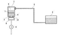
図7は、従来のインクジェット記録装置のインク供給系の概略構成図を示している。図7に示すように、記録ヘッド1は装置本体に対して移動可能なキャリッジ(不図示)に搭載されている。インクタンク2は、装置本体に固定され、インクが少なくなったときには、インクタンク2を交換することができる。記録ヘッド1とインクタンク2とは供給チューブ4および継手等で構成されたインク流路により連結されている。インク流路の少なくとも一部には、柔軟性のあるチューブ(例えば、シリコンチューブ、ポリエチレンチューブ等)が用いられている。そのため、キャリッジは記録時には往復移動するが、キャリッジの移動がインク流路により妨げられることはない。インクタンク2には大気連通孔(不図示)が設けられ、インクタンク2の内部は大気中に連通している。したがって、記録ヘッド1からインクが吐出されると、インクはインクタンク2から供給チューブ4を経て、記録ヘッド1に補給される。記録ヘッド1の内部は、第一のインク室5と第二のインク室6が設けられている。第一のインク室5には、供給チューブ4を通って記録インクが充填される。第一のインク室5の下部に、第二のインク室6が設けられている。第二のインク室6は、第一のインク室5からフィルタ7を介してインクが導入され、記録素子チップ3へとインクを導くためのインク保持領域としての役割を果たしている。
FIG. 7 shows a schematic configuration diagram of an ink supply system of a conventional ink jet recording apparatus. As shown in FIG. 7, the
記録ヘッド1内の圧力は、吐出口からインクが漏れ出してこないように負圧状態に保たれている。記録ヘッド1内の圧力はインクタンク2のインク液面の位置によって決まる。したがって、インクタンク2内のインク液面の高さは記録ヘッド1の吐出口の高さよりも20〜100mm程度低い位置に設けることが好ましい。
The pressure in the
このようなインクジェット記録装置において、記録ヘッドへインクを初期充填するためには、記録装置本体内にある回復ユニットに内蔵されているキャップ8を記録ヘッド1の複数のオリフィス16(以下、ノズルともいう。)面を覆い密閉状態にする。そして、キャップ8と下流側で連通している吸引ポンプ9を動作させて行われる。ポンプ9が動作することで、記録ヘッド1およびインク流路内が負圧になり、インクタンク2よりインクが記録ヘッド1へと充填される。初期充填では、インクタンク2から記録ヘッド1までの空間を吸引排気しなければならず、ポンプの吸引力バラツキ等によって、インクを記録ヘッド内へ充填するために必要なポンプ駆動時間が変わる。したがって、このような充填方法は、記録ヘッド1へインクを充填することができるが、ポンプの吸引力バラツキ等を考慮し、ある程度過剰に吸引をする必要がある。その結果、多量の廃インクが発生することがある。
In such an ink jet recording apparatus, in order to initially fill the recording head with ink, the
また、インク流路に用いている柔軟性のある供給チューブ4は、ゴム製、樹脂製のものが用いられるため、若干のガス透過性を有する。インク充填後は、供給チューブ4内も記録ヘッド1内と同様に負圧になっているため、チューブ内には大気からチューブ壁を通して少しずつ空気が侵入し、気泡が発生することがある。その気泡が記録ヘッド1内の第一のインク室5に流れ込むと、記録ヘッド内部の負圧維持が困難である。また、第二のインク室6へのインク供給が不十分となる結果、正常なインク滴を吐出できなくなり、記録不良が発生することがある。
Further, since the flexible supply tube 4 used for the ink flow path is made of rubber or resin, it has a slight gas permeability. After ink filling, the supply tube 4 has a negative pressure in the same manner as in the
この気泡を除去するために、前述した初期充填と同様に、オリフィス16の全面を覆い、ポンプ9を駆動させる方式がある。記録ヘッド1のインク流路内を負圧にしてインクをノズルよりキャップへ排出することにより、インクと一緒に気泡をノズルから排出することで気泡処理を行なうことができる。このような吸引回復方式による気泡除去は、回復動作時に廃インクが発生することになる。
In order to remove the bubbles, there is a system in which the entire surface of the
そこで、気泡が発生してもその気泡が記録ヘッド内に入り込まず、インク室内部の気泡を循環により除去するために、ポンプを使用したインク循環システムがある(例えば、特許文献1参照)。この方式では、記録ヘッドのインク室内にインク流入口とインク流出口が設けられている。そして、インクタンクは管部材を通じて記録ヘッドのインク流入口、インク流入口と連通しており、またインク流出口とインクタンク間の途中に循環ポンプが設けられてインクタンクへ連通する構成となっている。このような構成の循環システムでは、記録ヘッドへ初期充填するために、まず、循環ポンプを駆動させる。すると、インクはインクタンクから管部材を通じ記録ヘッドのインク流入口へと流れ、記録ヘッドにインクが充填される。インク流出口からインクタンクへ記録ヘッド内のインクが流れて記録ヘッド内の気液交換が行われる。そして、ノズルをキャップすることで、ノズル近傍に残った残留気泡は、ノズルから気泡をインクと共に吸引排出される。また、ノズルから吸引したインクは、切り替え弁により、廃液タンク若しくは、インクタンクへと流れるようになっている。このような方法により、廃インクの発生を抑えた初期充填を行なうことができる。
Therefore, there is an ink circulation system using a pump in order to remove bubbles inside the ink chamber by circulation even if bubbles are generated, and for example, refer to
ところで、一般に記録ヘッドには、工場出荷前に吐出性能を検査するために、記録インクが充填される。吐出性能検査を合格した記録ヘッドは、物流のために、記録ヘッド内のインクを記録ヘッドの保存に適した物流インクに置換される。物流過程で記録ヘッドに充填される物流用インクは、記録用インクに比べて、記録用インクの中の固着しやすい成分を極力減らし、かつ、水分蒸発を抑制するために水分比率を減らし、溶剤成分を増加させたものが用いられる。物流インクで充填された記録ヘッドは、工場出荷後、物流行程を経てユーザーの元に届けられる。物流用インクを内部に充填することにより、記録ヘッドの輸送中および保管中、記録ヘッドを良好な記録性能を発揮できる状態に維持することができる。 By the way, in general, the recording head is filled with recording ink in order to inspect the ejection performance before shipment from the factory. For the recording head that has passed the ejection performance inspection, the ink in the recording head is replaced with the distribution ink suitable for storage of the recording head for the purpose of distribution. The distribution ink that fills the recording head in the distribution process reduces the amount of components that are easily fixed in the recording ink as much as possible, and reduces the water ratio in order to suppress moisture evaporation. Those with increased ingredients are used. The recording head filled with the distribution ink is delivered to the user after the shipment from the factory through the trend of things. By filling the interior with the distribution ink, the recording head can be maintained in a state where good recording performance can be exhibited during transportation and storage of the recording head.
このような物流インクが充填された記録ヘッドに、上述した循環ポンプにより、インクタンク内の記録インクを初期充填すると、物流インクと記録インクが混ざることがある。また、物流インクがインクタンク内に混入することがある。さらに、記録ヘッド内に物流インクが存在している状態でインクが充填されるため、初期充填後、暫くの間は薄いインクが記録媒体上に吐出されることがある。 When a recording head filled with such distribution ink is initially filled with the recording ink in the ink tank by the circulation pump described above, the distribution ink and the recording ink may be mixed. In addition, logistics ink may be mixed in the ink tank. Further, since the ink is filled in the state where the distribution ink is present in the recording head, a thin ink may be ejected onto the recording medium for a while after the initial filling.
本発明は以上の点に鑑みてなされたものであり、記録ヘッドに記録インクを初期充填する際に、物流インクを記録ヘッドに残さず、さらに、廃インクを低減することができる、インク充填方法の提供を目的とする。 The present invention has been made in view of the above points, and an ink filling method capable of reducing waste ink without leaving the distribution ink in the recording head when the recording ink is initially filled in the recording head. The purpose is to provide.
上記目的を達成するために本発明は、インクをノズルから吐出する記録ヘッドと、前記記録ヘッドの記録面を覆うキャップと、前記インクを収容するインクタンクから前記記録ヘッドにインクを供給するためのインク供給路と、前記記録ヘッドから前記インクタンクにインクを導入するための排気経路と、前記排気経路に設けられたポンプと、前記インクと該インク中の気泡とを分離する気液分離手段と、を備えるインクジェット記録装置のインク充填方法であって、前記キャップから前記記録ヘッド内を吸引する第1の工程と、前記ポンプを動作させて前記排気経路から前記記録ヘッド内を吸引する第2の工程と、前記キャップから前記記録ヘッド内を吸引する第3の工程とを備えることを特徴とする。 To achieve the above object, the present invention provides a recording head that ejects ink from nozzles, a cap that covers the recording surface of the recording head, and an ink tank that supplies ink to the recording head from an ink tank that stores the ink. An ink supply path, an exhaust path for introducing ink from the recording head into the ink tank, a pump provided in the exhaust path, and a gas-liquid separation means for separating the ink and bubbles in the ink; A first step of sucking the inside of the recording head from the cap, and a second step of sucking the inside of the recording head from the exhaust path by operating the pump. And a third step of sucking the inside of the recording head from the cap.
以上の構成によれば、第1の工程により記録ヘッド内の物流インクを排気して、第2の工程によりインク中の気泡を除きながら記録ヘッド内にインクを充填する。そして、第3の工程でノズル近傍の気泡を除去することができる。その結果、記録ヘッドに記録インクを初期充填する際に、物流インクを記録ヘッドに残さず、さらに、廃インクを低減することができる。 According to the above configuration, the distribution ink in the recording head is exhausted in the first step, and the recording head is filled with ink while removing bubbles in the ink in the second step. Then, bubbles in the vicinity of the nozzle can be removed in the third step. As a result, when the recording ink is initially filled in the recording head, the distribution ink is not left on the recording head, and waste ink can be reduced.
以下に図面を参照して本発明における実施形態を詳細に説明する。 Embodiments of the present invention will be described below in detail with reference to the drawings.
(第1の実施形態)
本発明の実施の形態について図面を参照して説明する。
(First embodiment)
Embodiments of the present invention will be described with reference to the drawings.
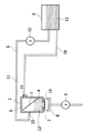
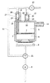
図1から図3は、本実施形態のインクジェット記録装置のインク供給系の概略構成を示す図である。図1は、記録ヘッドに記録インクを充填する前の状態を示している。図2および図3は、記録ヘッドに記録インクを充填する過程を示している。 1 to 3 are diagrams showing a schematic configuration of an ink supply system of the ink jet recording apparatus according to the present embodiment. FIG. 1 shows a state before the recording head is filled with recording ink. 2 and 3 show the process of filling the recording head with the recording ink.
記録ヘッド1は、インクジェット記録装置本体に対して移動可能なキャリッジに搭載され、記録ヘッド1から記録媒体に対して記録インクを吐出することにより画像を形成する。記録ヘッド1は、複数の記録素子と、インクを吐出するための複数のオリフィス16(以下、ノズルともいう。)が配列された記録素子チップ3と、第一のインク室5および第二のインク室6を備えている。また、記録ヘッド1の記録素子チップ3の記録面と対向して、記録装置本体内にある回復ユニットに内蔵されているキャップ8が備えられている。そして、キャップ8の下流側には吸引排気ポンプ9が設けられている。キャップ8を記録ヘッド1の記録面を覆い密閉状態にし、吸引廃棄ポンプ9を動作させて、記録ヘッド内を負圧にすることができる。
The
記録ヘッド1とインクタンク2とは、供給チューブ4および継手等で構成された2本のインク流路、すなわち、インク供給路10および排気経路11により連結されている。インクタンク2に収容された記録インク13は、インクタンク2からインク供給路10を経てインク流入口14から第一のインク室5に補給される。第一のインク室5の下方部には、フィルタ7を介して第二のインク室6が設けられている。第二のインク室6は、複数のオリフィス16に共通に接続されており、インクをチップ3に導くためのインク保持領域としての役割を果たすものである。第二のインク室6にはインク流出口15が設けられており、記録インク13は、インク流出口15から排気経路11を経てインクタンク2に導入される。
The
排気経路11の途中には、排気ポンプ12が設けられている。排気ポンプは、例えばピストンタイプもしくは複数のコロを回転させることにより、インクの流れを作っている。記録ヘッド1内の圧力は、記録ヘッド1からインク13が漏れ出してこないように負圧状態に保たれている。本実施形態の記録ヘッド1内の圧力は、インクタンク2の水面レベルにより決まることから、インクタンク2は、記録ヘッド(吐出口面)の高さよりも20〜100mm程度低い位置に設けることが好ましい。記録ヘッド1の記録インク13は、ポンプ12によってインクタンク2に移送される。インクタンク2には大気連通孔(不図示)が設けられている。この大気連通孔により、インクタンク2の内部は大気中に連通されているが、記録ヘッドは密閉構造になっているため大気中に連通されていない。
An
本実施形態の供給系では、排気経路11は、インクタンク2と連通しており、排気ポンプ12が動作することで、記録ヘッド1やインク供給路10および排気経路11の空気はインク13と共にインクタンク2内に運ばれる。その為、インクタンク2はインク中の気泡を除去するための気液分離手段としての機能を有する。排気ポンプ12によってインクタンク2内に運ばれた空気と記録インク13のうち、インク13は再度インク供給路10を通り記録ヘッドへと供給される。
In the supply system of the present embodiment, the
なお、ここでは1色のインク供給系について説明をしたが、複数色を使用する記録装置の場合、各色毎にインク供給系が備えられている。 Here, the ink supply system for one color has been described. However, in the case of a recording apparatus using a plurality of colors, an ink supply system is provided for each color.
次に、本実施形態のインク供給系における記録ヘッドへのインクの初期充填方法について説明をする。 Next, a method for initially filling the recording head with ink in the ink supply system of this embodiment will be described.
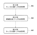
図4は、本実施形態の初期充填の工程を示すフローチャートである。初期充填は3つの工程(ステップS41からステップ43)からなる。 FIG. 4 is a flowchart showing the initial filling process of the present embodiment. Initial filling consists of three steps (from step S41 to step 43).
記録ヘッドにインク13を充填する前は、図1に示すように、記録ヘッド1の内部には、記録ヘッド1の保存に適した物流インク13´が充填されている。
Before filling the recording head with the
まず、ステップS41では、記録ヘッド1内の物流インク13´の除去を目的として第1の工程が行なわれる。第1の工程では、キャップ8で記録ヘッド1のノズルフェイス面を覆い密閉状態にしてから、キャップ8と下流側で連通している吸引排気ポンプ9を動作させる。吸引排気ポンプ9を動作させることで、記録ヘッド1のノズルを介して記録ヘッド1内の物流インク13´が吸引される。吸引された物流インク13´は、不図示の廃インク容器へと収納される。
First, in step S41, a first process is performed for the purpose of removing the distribution ink 13 'in the
図2は、第1の工程を行なった結果を示している。第1の工程中に、インクタンク2から記録インク13がインク供給路10の途中まで充填される。本実施形態では、物流インク13´の量はインク供給路10の容積よりも少ない。このため、物流インク13´の吸引排気動作中に、インクタンク2のインク13がインク供給路10全体を充填して記録ヘッド1内へ流れ込むことは無い。
FIG. 2 shows the result of performing the first step. During the first step, the
なお、物流インク13´の量がインク供給路10の容積より多い場合は、インクタンク2をインク供給系に装着せず、第1の工程を実施してもよい。すなわち、インク供給路10がインクタンク2と接続せずに大気開放された状態で、第1の工程を実施し、第1の工程終了後にインクタンク2を装着してもよい。
When the amount of the
次に、ステップS42では、記録ヘッド1およびインク供給路10にインク13を供給する目的として第2の工程が行なわれる。また、排気経路11にもインク13の充填を行う。第2の工程では、排気ポンプ12を動作させて、インクタンク2内の記録インク13が、インク供給路10を通じて記録ヘッド1内へ充填さる。このとき、記録ヘッド1のノズルにメニスカスが形成されていない為、キャップ8でノズルフェイス面をキャップした状態で排気ポンプ12を動作させる。そして、記録ヘッド1内から流出口15を通じて排気経路11にインク13が充填される。第2の工程により、記録ヘッド1やインク供給路10および排気経路11中の空気は排気ポンプ12により、記録インク13と共にインクタンク2へと運ばれる。記録ヘッド1、インク供給路10および排気経路11がインク13で充填された後、排気ポンプ12を停止する。
Next, in step S42, a second step is performed for the purpose of supplying the
図3は、第2の工程を行なった結果を示している。すなわち、記録ヘッド1、インク供給路10および排気経路11がインク13で充填された状態を示している。
FIG. 3 shows the result of performing the second step. That is, the
なお、第2の工程動作前、すなわち排気ポンプ12を動作させる前に、記録装置本体に供えられたワイピング装置(不図示)により、ノズルフェイス面の周囲を清掃し、ノズルフェイス面に残存した物流インク13´を除去してもよい。また、キャップ8と記録ヘッド1を離間した状態で、吸引廃棄ポンプ9を動作させて、キャップ8上に残った物流インク13´を除去してもよい。ノズルフェイス面とキャップ8の間に物流インク13´が残った状態で排気ポンプ12を動作した場合に、キャップ8上のゴミや塵が物流インク13´が記録ヘッド1に混入するのを防ぐ効果がある。
Before the second process operation, that is, before the
次に、ステップS43では、ノズル近傍のインク中の空気除去と、ノズルでのメニスカス形成することを目的として第3の工程が行なわれる。第3の工程では、キャップ8でノズルフェイス面をキャップした状態のまま、吸引排気ポンプ9を動作させて、記録ヘッド1のノズル内の空気を除去する。吸引排気ポンプ9の必要排気量は、ノズル近傍の容積分のみである。吸引排気ポンプ9を動作させることにより、空気と共に、記録インク13も排出される。ノズル近傍の容積分のみの排気量を吸引することで、ポンプの排気バラツキを考慮したとしても、発生する廃インク量を低く抑えることができる。
Next, in step S43, a third step is performed for the purpose of removing air in the ink near the nozzle and forming a meniscus at the nozzle. In the third step, the air in the nozzles of the
以上のように、キャップから記録ヘッド内を吸引する第1の工程と、ポンプを動作させて排気経路から記録ヘッド内を吸引する第2の工程と、キャップから記録ヘッド内を吸引する第3の工程とを行なう。これにより、物流インクが記録ヘッドに残らず、また、廃インクを低減することができる。 As described above, the first step of sucking the inside of the recording head from the cap, the second step of sucking the inside of the recording head from the exhaust path by operating the pump, and the third step of sucking the inside of the recording head from the cap. Process. Thereby, the distribution ink does not remain in the recording head, and the waste ink can be reduced.
(第2の実施形態)
第1の実施形態ではインク供給系として、インク循環系について説明をした。しかしながら本発明は、インク循環系のみに適用されるものではない。第1の実施形態では、インクタンクが気液分離手段として機能を果たしたが、気液分離手段として別の方法を用いても良い。
(Second Embodiment)
In the first embodiment, the ink circulation system has been described as the ink supply system. However, the present invention is not applied only to the ink circulation system. In the first embodiment, the ink tank functions as a gas-liquid separation unit. However, another method may be used as the gas-liquid separation unit.
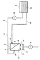
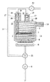
図5および図6は、本実施形態のインク供給系の概略構成を示す図である。本実施形態では、気液分離手段としてフロートを用いたインク供給系である。 5 and 6 are diagrams showing a schematic configuration of the ink supply system of the present embodiment. In the present embodiment, the ink supply system uses a float as the gas-liquid separation means.
本実施形態のインク供給系では、第一のインク室5および第二のインク室6それぞれにインク流出口15が設けられている。インク流出口15の上部にはそれぞれインク中の気泡等を除去するための気液分離手段17が設けられている。気液分離手段17は、円錐状のシール部18、球状のフロート部材19およびフロート部材19が移動可能なフロート室20により構成されている。球状のフロート部材19は、記録インク等の液体よりも比重の小さい部材により形成されている。フロート部材19は、シール部18と接触することにより流路を遮断する。
In the ink supply system of the present embodiment, an
インク流入口14はインクタンク(不図示)とチューブ等により接続されている。また、切り替え弁21により、キャップ8とポンプ9が連通した状態と、排気経路11とポンプ9が連通した状態をそれぞれ作り出せる構成となっている。つまり、ポンプ9は、キャップ8から記録ヘッド1を吸引する吸引排気ポンプと、排気経路11から記録ヘッド1を排気する排気ポンプの両方の機能を備えている。また、排気経路11中には、排気経路を大気開放する為の大気開放弁23が設けられている。
The
本実施形態のインク供給系では、第1の工程で、切り替え弁21によりキャップ8とポンプ9とを連通させた状態でポンプ9を動作させる。その結果、記録ヘッド1内の物流インク13´が吸引廃棄される。
In the ink supply system of this embodiment, in the first step, the
なお、物流インク13´の量がインク供給路の容積より多い場合は、インクタンクを記録装置に装着せずに、インク供給路がインクタンクと接続せず大気開放された状態で、本工程を実施し、第1の工程終了後にインクタンクを装着してもよい。また、排気経路11中の大気開放弁23を開いた状態で、ポンプ9を動作させてもよい。
If the amount of the distribution ink 13 'is larger than the volume of the ink supply path, this step is performed with the ink tank not attached to the recording apparatus and the ink supply path is not connected to the ink tank and is open to the atmosphere. The ink tank may be attached after the first step. Alternatively, the
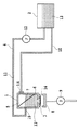
次に、第2の工程では、切り替え弁21により排気経路11とポンプ9を連通した状態でポンプ9を動作させる。この状態で、記録ヘッド1内の空気が排気されると共にインクタンクからインク13が記録ヘッド1内に充填される。そして、記録ヘッド1内のインク液面は気液分離手段17まで上昇する。インク液面の上昇と共に、フロート部材19も上昇していく。フロート部材19は、最初はフロート室20内で水平方向の位置が定まらないまま上昇してくるが、シール部18に達するとその後はシール部18の仮想頂点に近づくように上昇する。そして最後には、シール部18に全周が接触する位置で停止し、排気経路11を塞ぐことで、記録ヘッドへの充填が実現する。
Next, in the second step, the
図6は、第2の工程を行なった結果を示している。すなわち、記録ヘッド1、インク供給路および排気経路11がインク13で充填された状態を示している。
FIG. 6 shows the result of performing the second step. That is, the
次に、第3の工程では、切り替え弁21によりキャップ8とポンプ9とを連通させた状態でポンプ9を動作させる。その結果、記録ヘッド1のノズル近傍の空気が記録ヘッド1から除去される。
Next, in the third step, the
なお、フロート部材19は、それ自体の比重がインクより小さいものであればよい。すなわち、フロート部材19の材質は、例えばポリプロピレンを用いた部材のように、インクより比重が小さく、かつインクと反応しにくい材質であってもよい。また、インクより比重の大きい材質でも、中空等であり、部品そのもののみかけ比重がインクより小さければよい。
The
1 記録ヘッド
2 インクタンク
3 記録素子チップ
4 供給チューブ
5 第一のインク室
6 第二のインク室
7 フィルタ
8 キャップ
9 吸引排気ポンプ
10 インク供給路
11 排気経路
12 排気ポンプ
13 記録インク
13´ 物流インク
14 流入口
15 流出口
17 気液分離手段
22 ポンプ
23 大気開放弁
DESCRIPTION OF
Claims (5)
前記キャップから前記記録ヘッド内を吸引する第1の工程と、
前記ポンプを動作させて前記排気経路から前記記録ヘッド内を吸引する第2の工程と、
前記キャップから前記記録ヘッド内を吸引する第3の工程と
を備えることを特徴とするインク充填方法。 A recording head that ejects ink from nozzles; a cap that covers a recording surface of the recording head; an ink supply path for supplying ink from an ink tank that contains the ink to the recording head; and the ink from the recording head An ink filling method for an ink jet recording apparatus, comprising: an exhaust path for introducing ink into a tank; a pump provided in the exhaust path; and a gas-liquid separation unit that separates the ink and bubbles in the ink. There,
A first step of sucking the inside of the recording head from the cap;
A second step of operating the pump to suck the inside of the recording head from the exhaust path;
And a third step of sucking the inside of the recording head from the cap.
Priority Applications (1)
| Application Number | Priority Date | Filing Date | Title |
|---|---|---|---|
| JP2008322551A JP2010143070A (en) | 2008-12-18 | 2008-12-18 | Ink filling method |
Applications Claiming Priority (1)
| Application Number | Priority Date | Filing Date | Title |
|---|---|---|---|
| JP2008322551A JP2010143070A (en) | 2008-12-18 | 2008-12-18 | Ink filling method |
Publications (1)
| Publication Number | Publication Date |
|---|---|
| JP2010143070A true JP2010143070A (en) | 2010-07-01 |
Family
ID=42563999
Family Applications (1)
| Application Number | Title | Priority Date | Filing Date |
|---|---|---|---|
| JP2008322551A Pending JP2010143070A (en) | 2008-12-18 | 2008-12-18 | Ink filling method |
Country Status (1)
| Country | Link |
|---|---|
| JP (1) | JP2010143070A (en) |
Cited By (4)
| Publication number | Priority date | Publication date | Assignee | Title |
|---|---|---|---|---|
| JP2012236292A (en) * | 2011-05-10 | 2012-12-06 | Ricoh Co Ltd | Image forming apparatus |
| JP2013086439A (en) * | 2011-10-21 | 2013-05-13 | Canon Inc | Inkjet printing apparatus and method for discharging distribution ink |
| JP2016068314A (en) * | 2014-09-29 | 2016-05-09 | ブラザー工業株式会社 | Liquid spraying device and liquid substituting method |
| EP2962855A3 (en) * | 2014-06-30 | 2016-07-20 | Canon Finetech Inc. | Liquid accommodating container, liquid ejecting device and liquid introducing method |
-
2008
- 2008-12-18 JP JP2008322551A patent/JP2010143070A/en active Pending
Cited By (5)
| Publication number | Priority date | Publication date | Assignee | Title |
|---|---|---|---|---|
| JP2012236292A (en) * | 2011-05-10 | 2012-12-06 | Ricoh Co Ltd | Image forming apparatus |
| JP2013086439A (en) * | 2011-10-21 | 2013-05-13 | Canon Inc | Inkjet printing apparatus and method for discharging distribution ink |
| EP2962855A3 (en) * | 2014-06-30 | 2016-07-20 | Canon Finetech Inc. | Liquid accommodating container, liquid ejecting device and liquid introducing method |
| US9592670B2 (en) | 2014-06-30 | 2017-03-14 | Canon Finetech Inc. | Liquid accommodating container, liquid ejecting device and liquid introducing method |
| JP2016068314A (en) * | 2014-09-29 | 2016-05-09 | ブラザー工業株式会社 | Liquid spraying device and liquid substituting method |
Similar Documents
| Publication | Publication Date | Title |
|---|---|---|
| JP5676858B2 (en) | Recording device | |
| JP5078548B2 (en) | Discharging device and recording device | |
| JP2002321387A (en) | Storage form of ink jet head and method for liquid filling during storage of ink jet head | |
| JP4677296B2 (en) | Recording device | |
| JP2007519547A (en) | How to remove gas from a printhead | |
| JP2010143070A (en) | Ink filling method | |
| JP2010012773A (en) | Liquid ejecting head, liquid ejecting/recording device, and liquid filling method for liquid ejecting head | |
| US9527287B2 (en) | Droplet ejecting apparatus | |
| JP2010143071A (en) | Ink filling method | |
| JP2004009475A (en) | Ink jet recording device and ink supply device used therein | |
| JP6671898B2 (en) | Ink jet recording apparatus and liquid supply method | |
| JP2010120340A (en) | Fluid discharging device and recording device | |
| JP2011046109A (en) | Air discharging method for inkjet recording device | |
| JP2010143069A (en) | Ink-jet recording device | |
| JP2568989B2 (en) | Ink suction method for ink jet recording apparatus | |
| JP5359208B2 (en) | Liquid ejecting apparatus and liquid containing apparatus | |
| JP2008296476A (en) | Liquid droplet jet apparatus | |
| JP5026236B2 (en) | Ink jet recording apparatus and cleaning control method thereof | |
| JP2012196816A (en) | Liquid discharging apparatus | |
| JP4218960B2 (en) | Ink container and recording apparatus | |
| JP2004066463A (en) | Liquid drop ejection recorder and its ink filling method | |
| JP4691943B2 (en) | Bubble discharging method and droplet discharging method | |
| JP2014030964A (en) | Inkjet recording apparatus | |
| JP5487751B2 (en) | Cleaning device, liquid ejecting apparatus, and cleaning method for liquid ejecting apparatus | |
| US20230294414A1 (en) | Flow path unit and liquid ejection device |
Legal Events
| Date | Code | Title | Description |
|---|---|---|---|
| RD02 | Notification of acceptance of power of attorney |
Effective date: 20101106 Free format text: JAPANESE INTERMEDIATE CODE: A7422 |