EP3067139A1 - Wire electric discharge machine having function of cleaning inside of machining tank - Google Patents
Wire electric discharge machine having function of cleaning inside of machining tank Download PDFInfo
- Publication number
- EP3067139A1 EP3067139A1 EP16159515.2A EP16159515A EP3067139A1 EP 3067139 A1 EP3067139 A1 EP 3067139A1 EP 16159515 A EP16159515 A EP 16159515A EP 3067139 A1 EP3067139 A1 EP 3067139A1
- Authority
- EP
- European Patent Office
- Prior art keywords
- machining
- electric discharge
- machining tank
- image
- camera
- Prior art date
- Legal status (The legal status is an assumption and is not a legal conclusion. Google has not performed a legal analysis and makes no representation as to the accuracy of the status listed.)
- Withdrawn
Links
Images


Classifications
-
- B—PERFORMING OPERATIONS; TRANSPORTING
- B23—MACHINE TOOLS; METAL-WORKING NOT OTHERWISE PROVIDED FOR
- B23H—WORKING OF METAL BY THE ACTION OF A HIGH CONCENTRATION OF ELECTRIC CURRENT ON A WORKPIECE USING AN ELECTRODE WHICH TAKES THE PLACE OF A TOOL; SUCH WORKING COMBINED WITH OTHER FORMS OF WORKING OF METAL
- B23H1/00—Electrical discharge machining, i.e. removing metal with a series of rapidly recurring electrical discharges between an electrode and a workpiece in the presence of a fluid dielectric
-
- B—PERFORMING OPERATIONS; TRANSPORTING
- B23—MACHINE TOOLS; METAL-WORKING NOT OTHERWISE PROVIDED FOR
- B23H—WORKING OF METAL BY THE ACTION OF A HIGH CONCENTRATION OF ELECTRIC CURRENT ON A WORKPIECE USING AN ELECTRODE WHICH TAKES THE PLACE OF A TOOL; SUCH WORKING COMBINED WITH OTHER FORMS OF WORKING OF METAL
- B23H1/00—Electrical discharge machining, i.e. removing metal with a series of rapidly recurring electrical discharges between an electrode and a workpiece in the presence of a fluid dielectric
- B23H1/10—Supply or regeneration of working media
-
- B—PERFORMING OPERATIONS; TRANSPORTING
- B08—CLEANING
- B08B—CLEANING IN GENERAL; PREVENTION OF FOULING IN GENERAL
- B08B3/00—Cleaning by methods involving the use or presence of liquid or steam
- B08B3/02—Cleaning by the force of jets or sprays
- B08B3/024—Cleaning by means of spray elements moving over the surface to be cleaned
-
- B—PERFORMING OPERATIONS; TRANSPORTING
- B08—CLEANING
- B08B—CLEANING IN GENERAL; PREVENTION OF FOULING IN GENERAL
- B08B9/00—Cleaning hollow articles by methods or apparatus specially adapted thereto
-
- B—PERFORMING OPERATIONS; TRANSPORTING
- B23—MACHINE TOOLS; METAL-WORKING NOT OTHERWISE PROVIDED FOR
- B23H—WORKING OF METAL BY THE ACTION OF A HIGH CONCENTRATION OF ELECTRIC CURRENT ON A WORKPIECE USING AN ELECTRODE WHICH TAKES THE PLACE OF A TOOL; SUCH WORKING COMBINED WITH OTHER FORMS OF WORKING OF METAL
- B23H11/00—Auxiliary apparatus or details, not otherwise provided for
-
- B—PERFORMING OPERATIONS; TRANSPORTING
- B25—HAND TOOLS; PORTABLE POWER-DRIVEN TOOLS; MANIPULATORS
- B25J—MANIPULATORS; CHAMBERS PROVIDED WITH MANIPULATION DEVICES
- B25J11/00—Manipulators not otherwise provided for
- B25J11/008—Manipulators for service tasks
- B25J11/0085—Cleaning
-
- B—PERFORMING OPERATIONS; TRANSPORTING
- B25—HAND TOOLS; PORTABLE POWER-DRIVEN TOOLS; MANIPULATORS
- B25J—MANIPULATORS; CHAMBERS PROVIDED WITH MANIPULATION DEVICES
- B25J9/00—Program-controlled manipulators
- B25J9/16—Program controls
- B25J9/1694—Program controls characterised by use of sensors other than normal servo-feedback from position, speed or acceleration sensors, perception control, multi-sensor controlled systems, sensor fusion
- B25J9/1697—Vision controlled systems
-
- G—PHYSICS
- G01—MEASURING; TESTING
- G01N—INVESTIGATING OR ANALYSING MATERIALS BY DETERMINING THEIR CHEMICAL OR PHYSICAL PROPERTIES
- G01N21/00—Investigating or analysing materials by the use of optical means, i.e. using sub-millimetre waves, infrared, visible or ultraviolet light
- G01N21/84—Systems specially adapted for particular applications
- G01N21/88—Investigating the presence of flaws or contamination
- G01N21/94—Investigating contamination, e.g. dust
-
- G—PHYSICS
- G06—COMPUTING OR CALCULATING; COUNTING
- G06T—IMAGE DATA PROCESSING OR GENERATION, IN GENERAL
- G06T7/00—Image analysis
- G06T7/0002—Inspection of images, e.g. flaw detection
- G06T7/0004—Industrial image inspection
- G06T7/001—Industrial image inspection using an image reference approach
-
- B—PERFORMING OPERATIONS; TRANSPORTING
- B08—CLEANING
- B08B—CLEANING IN GENERAL; PREVENTION OF FOULING IN GENERAL
- B08B9/00—Cleaning hollow articles by methods or apparatus specially adapted thereto
- B08B9/08—Cleaning containers, e.g. tanks
- B08B9/093—Cleaning containers, e.g. tanks by the force of jets or sprays
-
- B—PERFORMING OPERATIONS; TRANSPORTING
- B23—MACHINE TOOLS; METAL-WORKING NOT OTHERWISE PROVIDED FOR
- B23H—WORKING OF METAL BY THE ACTION OF A HIGH CONCENTRATION OF ELECTRIC CURRENT ON A WORKPIECE USING AN ELECTRODE WHICH TAKES THE PLACE OF A TOOL; SUCH WORKING COMBINED WITH OTHER FORMS OF WORKING OF METAL
- B23H7/00—Processes or apparatus applicable to both electrical discharge machining and electrochemical machining
- B23H7/02—Wire-cutting
-
- G—PHYSICS
- G01—MEASURING; TESTING
- G01N—INVESTIGATING OR ANALYSING MATERIALS BY DETERMINING THEIR CHEMICAL OR PHYSICAL PROPERTIES
- G01N21/00—Investigating or analysing materials by the use of optical means, i.e. using sub-millimetre waves, infrared, visible or ultraviolet light
- G01N21/84—Systems specially adapted for particular applications
- G01N21/88—Investigating the presence of flaws or contamination
- G01N21/90—Investigating the presence of flaws or contamination in a container or its contents
-
- G—PHYSICS
- G05—CONTROLLING; REGULATING
- G05B—CONTROL OR REGULATING SYSTEMS IN GENERAL; FUNCTIONAL ELEMENTS OF SUCH SYSTEMS; MONITORING OR TESTING ARRANGEMENTS FOR SUCH SYSTEMS OR ELEMENTS
- G05B2219/00—Program-control systems
- G05B2219/30—Nc systems
- G05B2219/40—Robotics, robotics mapping to robotics vision
- G05B2219/40607—Fixed camera to observe workspace, object, workpiece, global
-
- G—PHYSICS
- G05—CONTROLLING; REGULATING
- G05B—CONTROL OR REGULATING SYSTEMS IN GENERAL; FUNCTIONAL ELEMENTS OF SUCH SYSTEMS; MONITORING OR TESTING ARRANGEMENTS FOR SUCH SYSTEMS OR ELEMENTS
- G05B2219/00—Program-control systems
- G05B2219/30—Nc systems
- G05B2219/45—Nc applications
- G05B2219/45221—Edm, electrical discharge machining, electroerosion, ecm, chemical
-
- G—PHYSICS
- G06—COMPUTING OR CALCULATING; COUNTING
- G06T—IMAGE DATA PROCESSING OR GENERATION, IN GENERAL
- G06T2207/00—Indexing scheme for image analysis or image enhancement
- G06T2207/30—Subject of image; Context of image processing
- G06T2207/30108—Industrial image inspection
- G06T2207/30164—Workpiece; Machine component
-
- Y—GENERAL TAGGING OF NEW TECHNOLOGICAL DEVELOPMENTS; GENERAL TAGGING OF CROSS-SECTIONAL TECHNOLOGIES SPANNING OVER SEVERAL SECTIONS OF THE IPC; TECHNICAL SUBJECTS COVERED BY FORMER USPC CROSS-REFERENCE ART COLLECTIONS [XRACs] AND DIGESTS
- Y02—TECHNOLOGIES OR APPLICATIONS FOR MITIGATION OR ADAPTATION AGAINST CLIMATE CHANGE
- Y02P—CLIMATE CHANGE MITIGATION TECHNOLOGIES IN THE PRODUCTION OR PROCESSING OF GOODS
- Y02P70/00—Climate change mitigation technologies in the production process for final industrial or consumer products
- Y02P70/10—Greenhouse gas [GHG] capture, material saving, heat recovery or other energy efficient measures, e.g. motor control, characterised by manufacturing processes, e.g. for rolling metal or metal working
Definitions
- the present invention relates to a wire electric discharge machine having a function of cleaning a machining tank when the machining tank is contaminated with machining chips produced during electric discharge machining of a workpiece.
- a wire electric discharge machine applies voltage between a wire electrode and a workpiece disposed in a machining tank, thereby performing electric discharge machining of the workpiece.
- machining chips originating from the workpiece and the wire electrode are produced in each machining cycle.
- the machining chips are deposited on and contaminate a guide for applying the voltage to the wire electrode in the machining tank and a table on which the workpiece is set for the application of the voltage.
- machining chips are left deposited on the guide and the table, they may cause improper voltage application between the wire electrode and the workpiece, so that it is important to clean the inside of the machining tank including the guide and the table.
- Japanese Patent Application Laid-Open No. 2009-255223 discloses a technique in which abrasive particles and the like produced by water jet machining are removed from a machining tank by running water in a channel in the inner wall of the machining tank, in a multifunction machine for water jet machining and wire electric discharge machining.
- the object of the present invention is to provide a wire electric discharge machine having a function of cleaning the inside of a machining tank, capable of preventing a reduction in the rate of operation and malfunction due to dirt in the machining tank.
- a wire electric discharge machine comprises a camera configured to capture an image of the inside of a machining tank and determining unit configured to detect dirt in the machining tank based on the image captured by the camera, the dirt in the machining tank being detected by the determining unit.
- the wire electric discharge machine may further comprise a cleaning device configured to remove machining chips deposited in the machining tank and a robot comprising the camera and/or the cleaning device, and the machining chips in that position in the machining tank which corresponds to the image captured by the camera may be removed by the cleaning device when the dirt in the machining tank is detected by the determining unit.
- a cleaning device configured to remove machining chips deposited in the machining tank and a robot comprising the camera and/or the cleaning device, and the machining chips in that position in the machining tank which corresponds to the image captured by the camera may be removed by the cleaning device when the dirt in the machining tank is detected by the determining unit.
- the cleaning device may be configured to remove the machining chips by discharging a machining fluid as a cleaning solution by a machining fluid control pump as a drive source previously attached to the wire electric discharge machine.
- a predetermined spot to be shot by the camera may be set in the machining tank or a mark may be provided on the predetermined spot, and the determining unit may be configured to determine whether or not the inside of the machining tank is contaminated, based on the image of the predetermined spot captured by the camera, an image of the predetermined spot on which the mark is provided, a reference image of the predetermined spot captured in advance, or a reference image of the mark.
- the reference image may be updated, immediately after the machining chips are removed by the cleaning device, by the image of the predetermined spot captured by the camera or the image of the predetermined spot on which the mark is provided.
- the determining unit may be configured to derive at least one of data related to a luminosity, color saturation, hue, and contrast from the image of the predetermined spot captured by the camera and determine whether or not the inside of the machining tank is contaminated, based on the derived data.
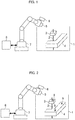
- FIG. 1 is a view showing a part of the configuration of the wire electric discharge machine, comprising a table on which a workpiece is set in the machining tank and a guide for applying voltage to a wire electrode.
- the wire electric discharge machine comprises a table 4, on which a workpiece (not shown) is set in a machining tank 1, and a guide 3 for applying voltage to a wire electrode 2.
- the wire electric discharge machine is generally controlled by a controller 20 so that a machining fluid 16 is injected through the guide 3 as the electric discharge machining is performed.
- the electric discharge machining is performed in such a manner that the workpiece is disposed between the guide 3 and another guide (not shown) and voltage is applied to a machining gap defined by the wire electrode 2 and the workpiece. Machining chips 17 originating from the wire electrode 2 and the workpiece are produced during the electric discharge machining.
- One embodiment of the wire electric discharge machine comprises a camera 5 for capturing an image of the inside of the machining tank 1 and a robot 7 mounted with a cleaning device 6 configured to inject a cleaning solution into the machining tank 1.
- a controller 8 controls the robot 7. Based on the image of the inside of the machining tank 1 captured by the camera 5, the controller 8 detects the deposition of machining chips on the guide 3 and the table 4. The controller 8 controls the cleaning device 6 to inject the cleaning solution and clean the guide 3, the table 4, and the inner wall of the machining tank 1.
- To clean the inside of the machining tank 1 means to clean the guide 3 and the table 4, as well as the inner wall of the machining tank 1.
- the wire electrode 2 is stretched between the guide 3 and the other guide (not shown). Normally, however, the inside of the machining tank 1 is cleaned without the wire electrode 2 between the guides. Since the machining chips deposited in the machining tank 1 are automatically detected and cleaned by the robot 7, an operator's burden can be reduced, and a reduction in the rate of operation and malfunction due to failure of cleaning can be prevented
- the controller 8 for the robot 7 and the controller 20 of the wire electric discharge machine exchange information with each other and are retracted to retracted positions so as not to hinder the electric discharge machining of the workpiece. In detecting or cleaning dirt in the machining tank 1, the controller 8 may be used to activate the robot 7 or control, in conjunction with the controller 20, the positions of the guide 3 and the like in the machining tank 1 so that the detecting or cleaning operation can be efficiently performed.
- FIG. 2 is a view showing how marks for the detection of the deposition of machining chips by the camera are arranged on the surfaces of the guide and the table.
- marks 9a for facilitating the detection of the deceleration of the machining chips 17 are arranged on the surfaces of the guide 3 and the table 4.
- the camera 5 captures an image of an area in the machining tank 1 in which the marks 9a are arranged, and data on the captured image is delivered to the controller 8.
- the controller 8 determines whether or not the marks 9a are hidden by dirt from the machining chips 17. If the marks 9a are hidden by the dirt, the inside of the machining tank 1 is cleaned by the cleaning device 6. The area in the machining tank 1 containing the marks is shot by the camera 5 after cleaning. If the marks 9a are still hidden, they are re-cleaned. If the marks 9a are recognized, the cleaning is completed. If the marks 9a are determined to be hidden without the installation of the cleaning device 6, an alarm signal may be given by the controller 8 to urge the operator to clean the inside of the machining tank 1.
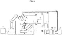
- FIG. 3 is a diagram showing a drive source of the cleaning device.
- the cleaning device 6 can clean the inside of the machining tank 1 with the machining fluid 16 used for the electric discharge machining.
- any one of pumps 10, 11, 13 and 15, which are previously attached to the wire electric discharge machine, may be diverted to the drive source of the cleaning device 6.
- the pump 10 is used to discharge the machining fluid 16 into the machining gap (defined between the wire electrode 2 and the workpiece).
- the pump 11 is used to collect the machining fluid 16 in the machining tank 1.
- the pump 13 is used to circulate the machining fluid 16 in an ion-exchange resin 12 in order to adjust the specific resistance of the machining fluid.
- the pump 15 is used to circulate the machining fluid 16 through a filter 14 in order to remove impurities such as the machining chips 17 mixed in the machining fluid.
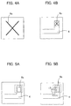
- FIGS. 4A and 4B are diagrams showing an example of a mark for the detection of the deposition of machining chips. Whether or not the mark 9a is hidden is determined by storing an image of a previously prepared reference mark, such as that shown in FIG. 4A , in advance in a memory of the controller 8 and comparing the stored image of the reference mark with the actual captured image of the mark 9a ( FIG. 4B ). Based on this comparison, the deposition may be identified if the rate of concordance between the images is lower than a predetermined value.
- the mark may be formed of a groove or projection such that a decision can be made based on the extent to which it is filled.
- FIG. 5A and 5B are diagrams showing an example in which the mark is formed by painting a predetermined area with a specified color. Further, a symbol such as the mark 9a may be replaced with a mark 9b with the specified color, as shown in FIG. 5A . If the color luminosity or pixel number is less than a reference value, it is determined that the colored area shown in FIG. 5B is narrower than a predetermined width, as shown in FIG. 5B , whereby the deposition of the machining chips 17 is identified.
- the reference mark is cleaned to overcome aging degradation of the guide 3 and the table 4. If this is done, an image of the reference mark captured on completion of the cleaning may be used for each cleaning cycle.
- the luminosity may be replaced with at least one of data related to the color saturation, hue, and contrast.
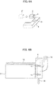
- FIGS. 6A and 6B are diagrams showing an example in which the cleaning device is mounted on the guide.
- the cleaning device 6 and the camera 5 are not mounted on the robot 7, and the camera 5 is attached to the upper part of the machining tank 1 of the wire electric discharge machine and used to shoot the inside of the machining tank 1.
- the cleaning device 6 for injecting the machining fluid 16 is attached to the guide 3 so that the table 4 can be cleaned by moving the guide 3 to a position above the table 4.
- the guide 3 may be cleaned by pouring the cleaning solution (machining fluid 16) over its upper part, as shown in FIG. 6B .
- the cleaning solution can be poured only over the guide 3 by closing a stopper 19.
- the cleaning solution can be poured only over the table 4 by closing a stopper 18.
- the machining fluid 16 for cleaning is supplied to the cleaning device 6 from the various pumps shown in FIG. 3 .
- FIG. 7 shows a flowchart.
- the number of cleaning cycles is set in advance in preparation for any trouble such as the deposition of dirt that cannot be removed by the cleaning device 6. If the number of cleaning cycles exceeds a set value, the operation is terminated and a warning is issued. In this way, the cleaning can be prevented from being endlessly repeated.
- the following is a sequential description of various steps of processing.
- Step sa01 An image of the inside of the machining tank is captured.
- Step sa02 It is determined whether or not the captured image of the inside of the machining tank is similar to a reference image. If the images are similar (YES), it is determined that the inside of the machining tank is not contaminated, whereupon the processing ends. If not (NO), it is determined that the inside of the machining tank is contaminated with machining chips, and the processing proceeds to Step sa03.
- Step sa03 It is determined whether or not the set value is exceeded by the number of cleaning cycles. If the set value is exceeded (YES), the processing proceeds to Step sa06. If not (NO), the processing proceeds to Step sa04.
- Step sa04 Cleaning by the cleaning device is started.
- Step sa05 The cleaning by a predetermined cleaning operation is terminated, whereupon the processing returns to Step sa01.
- Step sa06 Since the dirt (machining chips) cannot be removed despite the cleaning by the cleaning device, a warning is displayed.
- Step sa02 corresponds to "determining unit" described in Claims.
- FIG. 8 is flowchart illustrating a case in which a plurality of marks are arranged in various positions in the machining tank 1. Since the marks are located in the plurality of positions, each contaminated spot can be selectively cleaned. The following is a sequential description of various steps of processing.
- Step sb01 An image of the inside of the machining tank is captured.
- Step sb02 It is determined whether or not an image of a position S1 in the machining tank is similar to a reference image. If the images are similar (YES), the processing proceeds to Step sb04. If not (NO), the processing proceeds to Step sb03.
- Step sb03 Since it is determined in Step sb02 that the images are not similar, that is, the position S1 in the machining tank 1 is contaminated, cleaning of the vicinity of the position S1 is started.
- Step sb04 It is determined whether or not an image of a position SX in the machining tank is similar to a reference image. If the images are similar (YES), the processing proceeds to Step sb06. If not (NO), the processing proceeds to Step sb05. The determination on the similarity and the cleaning operation for other positions may be included in those for the positions S1 and SX.
- Step sb05 Since it is determined in Step sb04 that the images are not similar, that is, the position SX in the machining tank 1 is contaminated, cleaning of the vicinity of the position SX is started.
- Step sb06 It is determined whether or not all of images of the positions S1 to SX are similar to reference images. If all the images are similar (YES), then the positions S1 to SX in the machining tank are cleared of the dirt (machining chips 17), so that the processing ends. If all the images are not similar (NO), the processing proceeds to Step sa07.
- Step sb07 It is determined whether or not the set value is exceeded by the number of cleaning cycles. If the set value is not exceeded (NO), the processing returns to Step sb01. If the set value is exceeded (YES), the processing proceeds to Step sb08.
- Step sb08 Since the dirt (machining chips) cannot be removed despite the cleaning by the cleaning device, a warning is displayed.
- Steps sb02, sb04 and sb06 correspond to "determining unit" described in Claims.
Landscapes
- Engineering & Computer Science (AREA)
- Mechanical Engineering (AREA)
- Physics & Mathematics (AREA)
- General Physics & Mathematics (AREA)
- Robotics (AREA)
- Chemical & Material Sciences (AREA)
- Quality & Reliability (AREA)
- Health & Medical Sciences (AREA)
- General Health & Medical Sciences (AREA)
- Analytical Chemistry (AREA)
- Immunology (AREA)
- Pathology (AREA)
- Life Sciences & Earth Sciences (AREA)
- Computer Vision & Pattern Recognition (AREA)
- Theoretical Computer Science (AREA)
- Biochemistry (AREA)
- Electrical Discharge Machining, Electrochemical Machining, And Combined Machining (AREA)
- Chemical Kinetics & Catalysis (AREA)
- Electrochemistry (AREA)
- Image Analysis (AREA)
- Auxiliary Devices For Machine Tools (AREA)
- Machine Tool Sensing Apparatuses (AREA)
- Image Processing (AREA)
- Optics & Photonics (AREA)
- Cleaning By Liquid Or Steam (AREA)
Abstract
Description
- The present invention relates to a wire electric discharge machine having a function of cleaning a machining tank when the machining tank is contaminated with machining chips produced during electric discharge machining of a workpiece.
- A wire electric discharge machine applies voltage between a wire electrode and a workpiece disposed in a machining tank, thereby performing electric discharge machining of the workpiece. In this electric discharge machining, machining chips originating from the workpiece and the wire electrode are produced in each machining cycle. The machining chips are deposited on and contaminate a guide for applying the voltage to the wire electrode in the machining tank and a table on which the workpiece is set for the application of the voltage.
- If the machining chips are left deposited on the guide and the table, they may cause improper voltage application between the wire electrode and the workpiece, so that it is important to clean the inside of the machining tank including the guide and the table.
- Japanese Patent Application Laid-Open No.
2009-255223 - In general, an operator cleans the inside of a machining tank after visually determining how machining chips are deposited in the machining tank, so that there may occur a reduction in the rate of operation of a machine and malfunction due to failure of cleaning. According to the technique disclosed in Japanese Patent Application Laid-Open No.
2009-255223 - Accordingly, the object of the present invention is to provide a wire electric discharge machine having a function of cleaning the inside of a machining tank, capable of preventing a reduction in the rate of operation and malfunction due to dirt in the machining tank.
- A wire electric discharge machine according to the present invention comprises a camera configured to capture an image of the inside of a machining tank and determining unit configured to detect dirt in the machining tank based on the image captured by the camera, the dirt in the machining tank being detected by the determining unit.
- The wire electric discharge machine may further comprise a cleaning device configured to remove machining chips deposited in the machining tank and a robot comprising the camera and/or the cleaning device, and the machining chips in that position in the machining tank which corresponds to the image captured by the camera may be removed by the cleaning device when the dirt in the machining tank is detected by the determining unit.
- The cleaning device may be configured to remove the machining chips by discharging a machining fluid as a cleaning solution by a machining fluid control pump as a drive source previously attached to the wire electric discharge machine.
- In the wire electric discharge machine, a predetermined spot to be shot by the camera may be set in the machining tank or a mark may be provided on the predetermined spot, and the determining unit may be configured to determine whether or not the inside of the machining tank is contaminated, based on the image of the predetermined spot captured by the camera, an image of the predetermined spot on which the mark is provided, a reference image of the predetermined spot captured in advance, or a reference image of the mark.
- The reference image may be updated, immediately after the machining chips are removed by the cleaning device, by the image of the predetermined spot captured by the camera or the image of the predetermined spot on which the mark is provided.
- The determining unit may be configured to derive at least one of data related to a luminosity, color saturation, hue, and contrast from the image of the predetermined spot captured by the camera and determine whether or not the inside of the machining tank is contaminated, based on the derived data.
- The above and other objects and features of the present invention will be obvious from the ensuing description of embodiments with reference to the accompanying drawings, in which:
-
FIG. 1 is a view showing a part of the configuration of a wire electric discharge machine provided with a table on which a workpiece is set in a machining tank and a guide for applying voltage to a wire electrode; -
FIG. 2 is a view showing how marks for the detection of the deposition of machining chips by a camera are arranged on the surfaces of the guide and the table; -
FIG. 3 is a diagram showing a drive source of a cleaning device; -
FIGS. 4A and 4B are diagrams showing an example of a mark for the detection of the deposition of machining chips; -
FIGS. 5A and 5B are diagrams showing an example in which a mark is formed by painting a predetermined area with a specified color; -
FIGS. 6A and 6B are diagrams showing an example in which the cleaning device is mounted on the guide; -
FIG. 7 is a flowchart illustrating a case in which a single inspection point is provided; and -
FIG. 8 is a flowchart illustrating a case in which a plurality of inspection points are provided. - Embodiments of the present invention will now be described with reference to the accompanying drawings. The present invention can be applied to an electric discharge apparatus provided with a machining tank and configured to perform electric discharge machining in the machining tank. In the following description, a wire electric discharge machine is given as an example.
FIG. 1 is a view showing a part of the configuration of the wire electric discharge machine, comprising a table on which a workpiece is set in the machining tank and a guide for applying voltage to a wire electrode. - As shown in
FIG. 1 , the wire electric discharge machine comprises a table 4, on which a workpiece (not shown) is set in amachining tank 1, and aguide 3 for applying voltage to awire electrode 2. The wire electric discharge machine is generally controlled by a controller 20 so that amachining fluid 16 is injected through theguide 3 as the electric discharge machining is performed. The electric discharge machining is performed in such a manner that the workpiece is disposed between theguide 3 and another guide (not shown) and voltage is applied to a machining gap defined by thewire electrode 2 and the workpiece. Machiningchips 17 originating from thewire electrode 2 and the workpiece are produced during the electric discharge machining. Themachining chips 17, which are collected together with the machining fluid in a sewage tank (not shown), adhere to the surfaces of themachining tank 1 and theguide 3 in themachining tank 1. - One embodiment of the wire electric discharge machine according to the present invention comprises a
camera 5 for capturing an image of the inside of themachining tank 1 and arobot 7 mounted with acleaning device 6 configured to inject a cleaning solution into themachining tank 1. Acontroller 8 controls therobot 7. Based on the image of the inside of themachining tank 1 captured by thecamera 5, thecontroller 8 detects the deposition of machining chips on theguide 3 and the table 4. Thecontroller 8 controls thecleaning device 6 to inject the cleaning solution and clean theguide 3, the table 4, and the inner wall of themachining tank 1. To clean the inside of themachining tank 1 means to clean theguide 3 and the table 4, as well as the inner wall of themachining tank 1. - In
FIG. 1 , thewire electrode 2 is stretched between theguide 3 and the other guide (not shown). Normally, however, the inside of themachining tank 1 is cleaned without thewire electrode 2 between the guides. Since the machining chips deposited in themachining tank 1 are automatically detected and cleaned by therobot 7, an operator's burden can be reduced, and a reduction in the rate of operation and malfunction due to failure of cleaning can be prevented Thecontroller 8 for therobot 7 and the controller 20 of the wire electric discharge machine exchange information with each other and are retracted to retracted positions so as not to hinder the electric discharge machining of the workpiece. In detecting or cleaning dirt in themachining tank 1, thecontroller 8 may be used to activate therobot 7 or control, in conjunction with the controller 20, the positions of theguide 3 and the like in themachining tank 1 so that the detecting or cleaning operation can be efficiently performed. -
FIG. 2 is a view showing how marks for the detection of the deposition of machining chips by the camera are arranged on the surfaces of the guide and the table. As shown inFIG. 2 , marks 9a for facilitating the detection of the deceleration of the machining chips 17 (seeFIGS. 5 ) are arranged on the surfaces of theguide 3 and the table 4. Thecamera 5 captures an image of an area in themachining tank 1 in which themarks 9a are arranged, and data on the captured image is delivered to thecontroller 8. - The
controller 8 determines whether or not themarks 9a are hidden by dirt from themachining chips 17. If themarks 9a are hidden by the dirt, the inside of themachining tank 1 is cleaned by thecleaning device 6. The area in themachining tank 1 containing the marks is shot by thecamera 5 after cleaning. If themarks 9a are still hidden, they are re-cleaned. If themarks 9a are recognized, the cleaning is completed. If themarks 9a are determined to be hidden without the installation of thecleaning device 6, an alarm signal may be given by thecontroller 8 to urge the operator to clean the inside of themachining tank 1. -
FIG. 3 is a diagram showing a drive source of the cleaning device. Thecleaning device 6 can clean the inside of themachining tank 1 with themachining fluid 16 used for the electric discharge machining. As shown inFIG. 3 , any one ofpumps cleaning device 6. Thepump 10 is used to discharge themachining fluid 16 into the machining gap (defined between thewire electrode 2 and the workpiece). Thepump 11 is used to collect themachining fluid 16 in themachining tank 1. Thepump 13 is used to circulate themachining fluid 16 in an ion-exchange resin 12 in order to adjust the specific resistance of the machining fluid. Thepump 15 is used to circulate themachining fluid 16 through afilter 14 in order to remove impurities such as the machining chips 17 mixed in the machining fluid. -
FIGS. 4A and 4B are diagrams showing an example of a mark for the detection of the deposition of machining chips. Whether or not themark 9a is hidden is determined by storing an image of a previously prepared reference mark, such as that shown inFIG. 4A , in advance in a memory of thecontroller 8 and comparing the stored image of the reference mark with the actual captured image of themark 9a (FIG. 4B ). Based on this comparison, the deposition may be identified if the rate of concordance between the images is lower than a predetermined value. The mark may be formed of a groove or projection such that a decision can be made based on the extent to which it is filled. -
FIG. 5A and 5B are diagrams showing an example in which the mark is formed by painting a predetermined area with a specified color. Further, a symbol such as themark 9a may be replaced with amark 9b with the specified color, as shown inFIG. 5A . If the color luminosity or pixel number is less than a reference value, it is determined that the colored area shown inFIG. 5B is narrower than a predetermined width, as shown inFIG. 5B , whereby the deposition of the machining chips 17 is identified. The reference mark is cleaned to overcome aging degradation of theguide 3 and the table 4. If this is done, an image of the reference mark captured on completion of the cleaning may be used for each cleaning cycle. The luminosity may be replaced with at least one of data related to the color saturation, hue, and contrast. -
FIGS. 6A and 6B are diagrams showing an example in which the cleaning device is mounted on the guide. Thecleaning device 6 and thecamera 5 are not mounted on therobot 7, and thecamera 5 is attached to the upper part of themachining tank 1 of the wire electric discharge machine and used to shoot the inside of themachining tank 1. As shown inFIG. 6A , thecleaning device 6 for injecting themachining fluid 16 is attached to theguide 3 so that the table 4 can be cleaned by moving theguide 3 to a position above the table 4. Theguide 3 may be cleaned by pouring the cleaning solution (machining fluid 16) over its upper part, as shown inFIG. 6B . In cleaning only theguide 3 shown inFIG. 6B , the cleaning solution can be poured only over theguide 3 by closing astopper 19. In cleaning only the table 4, in contrast, the cleaning solution can be poured only over the table 4 by closing astopper 18. Themachining fluid 16 for cleaning is supplied to thecleaning device 6 from the various pumps shown inFIG. 3 . -
FIG. 7 shows a flowchart. The number of cleaning cycles is set in advance in preparation for any trouble such as the deposition of dirt that cannot be removed by thecleaning device 6. If the number of cleaning cycles exceeds a set value, the operation is terminated and a warning is issued. In this way, the cleaning can be prevented from being endlessly repeated. The following is a sequential description of various steps of processing. - [Step sa01] An image of the inside of the machining tank is captured.
- [Step sa02] It is determined whether or not the captured image of the inside of the machining tank is similar to a reference image. If the images are similar (YES), it is determined that the inside of the machining tank is not contaminated, whereupon the processing ends. If not (NO), it is determined that the inside of the machining tank is contaminated with machining chips, and the processing proceeds to Step sa03.
- [Step sa03] It is determined whether or not the set value is exceeded by the number of cleaning cycles. If the set value is exceeded (YES), the processing proceeds to Step sa06. If not (NO), the processing proceeds to Step sa04.
- [Step sa04] Cleaning by the cleaning device is started.
- [Step sa05] The cleaning by a predetermined cleaning operation is terminated, whereupon the processing returns to Step sa01.
- [Step sa06] Since the dirt (machining chips) cannot be removed despite the cleaning by the cleaning device, a warning is displayed.
- Step sa02 corresponds to "determining unit" described in Claims.
-
FIG. 8 is flowchart illustrating a case in which a plurality of marks are arranged in various positions in themachining tank 1. Since the marks are located in the plurality of positions, each contaminated spot can be selectively cleaned. The following is a sequential description of various steps of processing. - [Step sb01] An image of the inside of the machining tank is captured.
- [Step sb02] It is determined whether or not an image of a position S1 in the machining tank is similar to a reference image. If the images are similar (YES), the processing proceeds to Step sb04. If not (NO), the processing proceeds to Step sb03.
- [Step sb03] Since it is determined in Step sb02 that the images are not similar, that is, the position S1 in the
machining tank 1 is contaminated, cleaning of the vicinity of the position S1 is started. - [Step sb04] It is determined whether or not an image of a position SX in the machining tank is similar to a reference image. If the images are similar (YES), the processing proceeds to Step sb06. If not (NO), the processing proceeds to Step sb05. The determination on the similarity and the cleaning operation for other positions may be included in those for the positions S1 and SX.
- [Step sb05] Since it is determined in Step sb04 that the images are not similar, that is, the position SX in the
machining tank 1 is contaminated, cleaning of the vicinity of the position SX is started. - [Step sb06] It is determined whether or not all of images of the positions S1 to SX are similar to reference images. If all the images are similar (YES), then the positions S1 to SX in the machining tank are cleared of the dirt (machining chips 17), so that the processing ends. If all the images are not similar (NO), the processing proceeds to Step sa07.
- [Step sb07] It is determined whether or not the set value is exceeded by the number of cleaning cycles. If the set value is not exceeded (NO), the processing returns to Step sb01. If the set value is exceeded (YES), the processing proceeds to Step sb08.
- [Step sb08] Since the dirt (machining chips) cannot be removed despite the cleaning by the cleaning device, a warning is displayed.
- Steps sb02, sb04 and sb06 correspond to "determining unit" described in Claims.
- While an embodiment of the present invention has been described herein, the invention is not limited to the above-described embodiment and may be suitably modified and embodied in various forms.
Claims (6)
- A wire electric discharge machine configured to perform electric discharge machining in a machining tank, the workpiece comprising:a camera configured to capture an image of the inside of the machining tank; anddetermining unit configured to detect dirt in the machining tank based on the image captured by the camera,wherein the dirt in the machining tank is detected by the determining unit.
- The wire electric discharge machine according to claim 1, comprising a cleaning device configured to remove machining chips deposited in the machining tank and a robot comprising the camera and/or the cleaning device, wherein the machining chips in that position in the machining tank which corresponds to the image captured by the camera are removed by the cleaning device when the dirt in the machining tank is detected by the determining unit.
- The wire electric discharge machine according to claim 2, wherein the cleaning device removes the machining chips by discharging a machining fluid as a cleaning solution by a machining fluid control pump as a drive source previously attached to the wire electric discharge machine.
- The wire electric discharge machine according to any one of claims 1 to 3, wherein a predetermined spot to be shot by the camera is set in the machining tank or a mark is provided on the predetermined spot, and the determining unit determines whether or not the inside of the machining tank is contaminated, based on the image of the predetermined spot captured by the camera, an image of the predetermined spot on which the mark is provided, a reference image of the predetermined spot captured in advance, or a reference image of the mark.
- The wire electric discharge machine according to claim 4, wherein the reference image is updated, immediately after the machining chips are removed by the cleaning device, by the image of the predetermined spot captured by the camera or the image of the predetermined spot on which the mark is provided.
- The wire electric discharge machine according to claim 4 or 5, wherein the determining unit derives at least one of data related to a luminosity, color saturation, hue, and contrast from the image of the predetermined spot captured by the camera and determines whether or not the inside of the machining tank is contaminated, based on the derived data.
Applications Claiming Priority (1)
| Application Number | Priority Date | Filing Date | Title |
|---|---|---|---|
| JP2015050258A JP6193904B2 (en) | 2015-03-13 | 2015-03-13 | Wire electrical discharge machine with cleaning function in processing tank |
Publications (1)
| Publication Number | Publication Date |
|---|---|
| EP3067139A1 true EP3067139A1 (en) | 2016-09-14 |
Family
ID=55650084
Family Applications (1)
| Application Number | Title | Priority Date | Filing Date |
|---|---|---|---|
| EP16159515.2A Withdrawn EP3067139A1 (en) | 2015-03-13 | 2016-03-09 | Wire electric discharge machine having function of cleaning inside of machining tank |
Country Status (5)
| Country | Link |
|---|---|
| US (1) | US10265790B2 (en) |
| EP (1) | EP3067139A1 (en) |
| JP (1) | JP6193904B2 (en) |
| KR (1) | KR101970384B1 (en) |
| CN (1) | CN105965114A (en) |
Cited By (4)
| Publication number | Priority date | Publication date | Assignee | Title |
|---|---|---|---|---|
| EP3189921A3 (en) * | 2016-01-06 | 2017-10-04 | Fanuc Corporation | Wire electric discharge machine |
| CN109521770A (en) * | 2018-11-19 | 2019-03-26 | 佛山市第人民医院(中山大学附属佛山医院) | Intelligent processing system and method for bedding and clothing of patient |
| CN110293272A (en) * | 2019-08-08 | 2019-10-01 | 安徽理工大学 | A kind of electric spark and electrolysis electric discharge Compound Machining experimental rig for semicircle orifice |
| CN111230884A (en) * | 2020-02-28 | 2020-06-05 | 五邑大学 | Cleaning robot and its path moving method under PID control |
Families Citing this family (15)
| Publication number | Priority date | Publication date | Assignee | Title |
|---|---|---|---|---|
| JP6181687B2 (en) * | 2015-03-13 | 2017-08-16 | ファナック株式会社 | Processing machine system that can remove chips generated by processing |
| JP6356655B2 (en) * | 2015-12-10 | 2018-07-11 | ファナック株式会社 | Machining system with function to remove machining waste |
| JP6321703B2 (en) | 2016-03-04 | 2018-05-09 | ファナック株式会社 | Wire electrical discharge machine inspection system |
| US10581051B2 (en) | 2016-12-23 | 2020-03-03 | Sumitomo Chemical Company, Limited | Separator winding core, separator roll, and method of cleaning separator winding core |
| JP6502983B2 (en) | 2017-03-15 | 2019-04-17 | ファナック株式会社 | Cleaning process optimization device and machine learning device |
| CN107143340A (en) * | 2017-04-26 | 2017-09-08 | 中南大学 | A kind of major diameter slurry shield machine knife disc tool cleaning and outward appearance monitoring arrangement |
| JP6490154B2 (en) * | 2017-06-21 | 2019-03-27 | ファナック株式会社 | Wire discharge system and relative position calculation method |
| CN107597776B (en) * | 2017-09-08 | 2020-11-20 | 珠海格力电器股份有限公司 | Cleaning method and device for cooking equipment, cooking equipment |
| JP6886506B1 (en) * | 2019-11-29 | 2021-06-16 | Dmg森精機株式会社 | Display devices, image processing devices, machine tools and liquid discharge methods |
| KR20210067439A (en) | 2019-11-29 | 2021-06-08 | 주식회사 엠택코리아 | Cleaning apparatus for electric discharge machine and the cleaning method using the same |
| JP6886505B1 (en) | 2019-11-29 | 2021-06-16 | Dmg森精機株式会社 | Display devices, image processing devices, machine tools and liquid discharge methods |
| KR102353101B1 (en) | 2020-01-30 | 2022-01-19 | 한성대학교 산학협력단 | Cleaning apparatus for electric discharge machine |
| JPWO2022044882A1 (en) * | 2020-08-24 | 2022-03-03 | ||
| CN115156161A (en) * | 2021-04-07 | 2022-10-11 | 台州善敏机械有限公司 | Electroplated part washing method and electroplating method |
| CN117234153A (en) * | 2022-06-07 | 2023-12-15 | 北京小米移动软件有限公司 | Intelligent cleaning control method, system, electronic device and storage medium |
Citations (9)
| Publication number | Priority date | Publication date | Assignee | Title |
|---|---|---|---|---|
| US5408063A (en) * | 1992-10-26 | 1995-04-18 | Sodick Co., Ltd. | Fluid flushing device |
| JPH11104578A (en) * | 1997-09-30 | 1999-04-20 | Ooga:Kk | Work washing device using multijoint type robot |
| US20010043735A1 (en) * | 1998-10-15 | 2001-11-22 | Eugene Smargiassi | Detection of wafer fragments in a wafer processing apparatus |
| JP2004106142A (en) * | 2002-09-20 | 2004-04-08 | Mitsubishi Electric Corp | Wire electric discharge machine |
| DE202007006113U1 (en) * | 2007-04-26 | 2007-07-12 | Rst Regel- Und Steuerungsanlagen Gmbh | High pressure system for cleaning surfaces with high pressure fluid jet, comprises pressure conduit for adjusting volume flow rate in specified range, where pressure conduit with bent spiral section is arranged as metallic pressure pipe |
| US20080285840A1 (en) * | 2005-12-26 | 2008-11-20 | Nikon Corporation | Defect inspection apparatus performing defect inspection by image analysis |
| JP2009255223A (en) | 2008-04-16 | 2009-11-05 | Sodick Co Ltd | Composite processing device |
| US20120103367A1 (en) * | 2009-07-03 | 2012-05-03 | Ecovacs Robotics (Suzhou ) Co., Ltd. | Cleaning robot, dirt recognition device thereof and cleaning method of robot |
| US20120152877A1 (en) * | 2010-12-16 | 2012-06-21 | Saied Tadayon | Robot for Solar Farms |
Family Cites Families (7)
| Publication number | Priority date | Publication date | Assignee | Title |
|---|---|---|---|---|
| JPS63196326A (en) * | 1987-02-09 | 1988-08-15 | Inoue Japax Res Inc | Automatic electric discharge device |
| JPH02116419A (en) * | 1988-10-24 | 1990-05-01 | Fanuc Ltd | Circulating device for working fluid |
| JP2728628B2 (en) * | 1994-03-23 | 1998-03-18 | アミテック株式会社 | Cleaning method of belt sander and sanding belt |
| JPH08197383A (en) * | 1995-01-30 | 1996-08-06 | Toshiba Mach Co Ltd | Method and apparatus for detecting chip attachment of cutting tool |
| JP2004268220A (en) | 2003-03-11 | 2004-09-30 | Mitsubishi Electric Corp | Electric discharge machine |
| JP6338333B2 (en) * | 2013-07-25 | 2018-06-06 | 中村留精密工業株式会社 | Machine tool cleaning equipment |
| US9465386B2 (en) * | 2014-02-24 | 2016-10-11 | Hongfujin Precision Electronics (Cheng Du) Co., Ltd. | Mobile robotic trolley-based processing system and mobile robotic trolley thereof |
-
2015
- 2015-03-13 JP JP2015050258A patent/JP6193904B2/en not_active Expired - Fee Related
-
2016
- 2016-03-02 US US15/058,156 patent/US10265790B2/en not_active Expired - Fee Related
- 2016-03-09 EP EP16159515.2A patent/EP3067139A1/en not_active Withdrawn
- 2016-03-10 KR KR1020160028733A patent/KR101970384B1/en not_active Expired - Fee Related
- 2016-03-14 CN CN201610144837.2A patent/CN105965114A/en active Pending
Patent Citations (9)
| Publication number | Priority date | Publication date | Assignee | Title |
|---|---|---|---|---|
| US5408063A (en) * | 1992-10-26 | 1995-04-18 | Sodick Co., Ltd. | Fluid flushing device |
| JPH11104578A (en) * | 1997-09-30 | 1999-04-20 | Ooga:Kk | Work washing device using multijoint type robot |
| US20010043735A1 (en) * | 1998-10-15 | 2001-11-22 | Eugene Smargiassi | Detection of wafer fragments in a wafer processing apparatus |
| JP2004106142A (en) * | 2002-09-20 | 2004-04-08 | Mitsubishi Electric Corp | Wire electric discharge machine |
| US20080285840A1 (en) * | 2005-12-26 | 2008-11-20 | Nikon Corporation | Defect inspection apparatus performing defect inspection by image analysis |
| DE202007006113U1 (en) * | 2007-04-26 | 2007-07-12 | Rst Regel- Und Steuerungsanlagen Gmbh | High pressure system for cleaning surfaces with high pressure fluid jet, comprises pressure conduit for adjusting volume flow rate in specified range, where pressure conduit with bent spiral section is arranged as metallic pressure pipe |
| JP2009255223A (en) | 2008-04-16 | 2009-11-05 | Sodick Co Ltd | Composite processing device |
| US20120103367A1 (en) * | 2009-07-03 | 2012-05-03 | Ecovacs Robotics (Suzhou ) Co., Ltd. | Cleaning robot, dirt recognition device thereof and cleaning method of robot |
| US20120152877A1 (en) * | 2010-12-16 | 2012-06-21 | Saied Tadayon | Robot for Solar Farms |
Cited By (6)
| Publication number | Priority date | Publication date | Assignee | Title |
|---|---|---|---|---|
| EP3189921A3 (en) * | 2016-01-06 | 2017-10-04 | Fanuc Corporation | Wire electric discharge machine |
| CN109521770A (en) * | 2018-11-19 | 2019-03-26 | 佛山市第人民医院(中山大学附属佛山医院) | Intelligent processing system and method for bedding and clothing of patient |
| CN109521770B (en) * | 2018-11-19 | 2021-08-03 | 佛山市第一人民医院(中山大学附属佛山医院) | A system and method for intelligent processing of patient clothing |
| CN110293272A (en) * | 2019-08-08 | 2019-10-01 | 安徽理工大学 | A kind of electric spark and electrolysis electric discharge Compound Machining experimental rig for semicircle orifice |
| CN110293272B (en) * | 2019-08-08 | 2024-04-26 | 安徽理工大学 | A test device for electrospark discharge and electrodischarge composite machining of semicircular holes |
| CN111230884A (en) * | 2020-02-28 | 2020-06-05 | 五邑大学 | Cleaning robot and its path moving method under PID control |
Also Published As
| Publication number | Publication date |
|---|---|
| CN105965114A (en) | 2016-09-28 |
| US10265790B2 (en) | 2019-04-23 |
| US20160263687A1 (en) | 2016-09-15 |
| JP2016168649A (en) | 2016-09-23 |
| KR101970384B1 (en) | 2019-04-18 |
| JP6193904B2 (en) | 2017-09-06 |
| KR20160110210A (en) | 2016-09-21 |
Similar Documents
| Publication | Publication Date | Title |
|---|---|---|
| US10265790B2 (en) | Wire electric discharge machine having function of cleaning inside of machining tank | |
| DE102015122164B4 (en) | Processing device with visual sensor for locating dirt | |
| CN106607713B (en) | Tool cleaning device for machine tool | |
| US10086487B2 (en) | Internal cleaning device of machine tool | |
| DE102016121711B4 (en) | Machine tool | |
| EP2234778B1 (en) | Machine tool device and method with such a machine tool device | |
| WO2013041608A1 (en) | Cleaning system | |
| EP2497594A1 (en) | Working fluid filtration device of electric discharge machine | |
| DE102016125826B4 (en) | Machine tool | |
| DE102015013581B4 (en) | Numerical control | |
| CN106914667B (en) | Wire electric discharge machining system | |
| EP3034223B1 (en) | Controller for wire electric discharge machine having consumable exchange function | |
| DE102016121038A1 (en) | FOG REMOVAL SYSTEM AND FOG REMOVAL PROCEDURE | |
| CN103170688B (en) | Working fluid filtering device for electrical discharge machine | |
| DE102013017633A1 (en) | Numerical control device with thread cutting cycle function | |
| WO2022158420A1 (en) | Machine tool, machine tool control method, and machine tool control program | |
| KR101748936B1 (en) | Wire-cut electrical discharge machining machine in which position of liquid level of machining fluid is adjusted at time of automatic wire threading | |
| DE102018218370A1 (en) | LASER PROCESSING DEVICE | |
| DE60307203T2 (en) | Window device | |
| KR20160072789A (en) | Electric discharge machine | |
| JP3083869B2 (en) | Water and oil sculpture-type electric discharge machining method and apparatus | |
| JP6298025B2 (en) | Electric discharge machine having means for adding machining fluid | |
| DE19751665C1 (en) | Process and device for automatic color change in serial painting systems |
Legal Events
| Date | Code | Title | Description |
|---|---|---|---|
| PUAI | Public reference made under article 153(3) epc to a published international application that has entered the european phase |
Free format text: ORIGINAL CODE: 0009012 |
|
| AK | Designated contracting states |
Kind code of ref document: A1 Designated state(s): AL AT BE BG CH CY CZ DE DK EE ES FI FR GB GR HR HU IE IS IT LI LT LU LV MC MK MT NL NO PL PT RO RS SE SI SK SM TR |
|
| AX | Request for extension of the european patent |
Extension state: BA ME |
|
| 17P | Request for examination filed |
Effective date: 20170306 |
|
| RBV | Designated contracting states (corrected) |
Designated state(s): AL AT BE BG CH CY CZ DE DK EE ES FI FR GB GR HR HU IE IS IT LI LT LU LV MC MK MT NL NO PL PT RO RS SE SI SK SM TR |
|
| STAA | Information on the status of an ep patent application or granted ep patent |
Free format text: STATUS: THE APPLICATION HAS BEEN WITHDRAWN |
|
| 18W | Application withdrawn |
Effective date: 20190426 |