EP3066862B1 - Noeud de réseau et procédé de réglage de paramètres d'antenne dans un système de communications sans fil - Google Patents
Noeud de réseau et procédé de réglage de paramètres d'antenne dans un système de communications sans fil Download PDFInfo
- Publication number
- EP3066862B1 EP3066862B1 EP13795013.5A EP13795013A EP3066862B1 EP 3066862 B1 EP3066862 B1 EP 3066862B1 EP 13795013 A EP13795013 A EP 13795013A EP 3066862 B1 EP3066862 B1 EP 3066862B1
- Authority
- EP
- European Patent Office
- Prior art keywords
- antenna
- network node
- user equipments
- antennas
- cell
- Prior art date
- Legal status (The legal status is an assumption and is not a legal conclusion. Google has not performed a legal analysis and makes no representation as to the accuracy of the status listed.)
- Active
Links
- 238000000034 method Methods 0.000 title claims description 20
- 238000004891 communication Methods 0.000 title description 27
- 238000005259 measurement Methods 0.000 claims description 25
- 238000012545 processing Methods 0.000 claims description 13
- 230000001419 dependent effect Effects 0.000 claims description 6
- 238000009826 distribution Methods 0.000 description 30
- 230000002452 interceptive effect Effects 0.000 description 29
- 238000002955 isolation Methods 0.000 description 26
- 238000010586 diagram Methods 0.000 description 23
- 230000001186 cumulative effect Effects 0.000 description 15
- 238000005315 distribution function Methods 0.000 description 15
- 230000009471 action Effects 0.000 description 14
- 230000005540 biological transmission Effects 0.000 description 14
- 230000003044 adaptive effect Effects 0.000 description 6
- 230000001413 cellular effect Effects 0.000 description 6
- 238000004590 computer program Methods 0.000 description 4
- 230000011664 signaling Effects 0.000 description 3
- 230000010267 cellular communication Effects 0.000 description 2
- 230000000052 comparative effect Effects 0.000 description 2
- 230000005284 excitation Effects 0.000 description 2
- 238000007726 management method Methods 0.000 description 2
- 230000006978 adaptation Effects 0.000 description 1
- 230000009286 beneficial effect Effects 0.000 description 1
- 230000000694 effects Effects 0.000 description 1
- 230000006870 function Effects 0.000 description 1
- 230000003993 interaction Effects 0.000 description 1
- 238000012986 modification Methods 0.000 description 1
- 230000004048 modification Effects 0.000 description 1
- 238000005070 sampling Methods 0.000 description 1
- 239000007787 solid Substances 0.000 description 1
- 230000003442 weekly effect Effects 0.000 description 1
Images


Classifications
-
- H—ELECTRICITY
- H04—ELECTRIC COMMUNICATION TECHNIQUE
- H04W—WIRELESS COMMUNICATION NETWORKS
- H04W16/00—Network planning, e.g. coverage or traffic planning tools; Network deployment, e.g. resource partitioning or cells structures
- H04W16/24—Cell structures
- H04W16/28—Cell structures using beam steering
-
- H—ELECTRICITY
- H01—ELECTRIC ELEMENTS
- H01Q—ANTENNAS, i.e. RADIO AERIALS
- H01Q1/00—Details of, or arrangements associated with, antennas
- H01Q1/12—Supports; Mounting means
- H01Q1/22—Supports; Mounting means by structural association with other equipment or articles
- H01Q1/24—Supports; Mounting means by structural association with other equipment or articles with receiving set
- H01Q1/241—Supports; Mounting means by structural association with other equipment or articles with receiving set used in mobile communications, e.g. GSM
- H01Q1/246—Supports; Mounting means by structural association with other equipment or articles with receiving set used in mobile communications, e.g. GSM specially adapted for base stations
-
- H—ELECTRICITY
- H04—ELECTRIC COMMUNICATION TECHNIQUE
- H04L—TRANSMISSION OF DIGITAL INFORMATION, e.g. TELEGRAPHIC COMMUNICATION
- H04L43/00—Arrangements for monitoring or testing data switching networks
- H04L43/16—Threshold monitoring
-
- H—ELECTRICITY
- H04—ELECTRIC COMMUNICATION TECHNIQUE
- H04W—WIRELESS COMMUNICATION NETWORKS
- H04W24/00—Supervisory, monitoring or testing arrangements
- H04W24/08—Testing, supervising or monitoring using real traffic
-
- H—ELECTRICITY
- H04—ELECTRIC COMMUNICATION TECHNIQUE
- H04W—WIRELESS COMMUNICATION NETWORKS
- H04W72/00—Local resource management
- H04W72/50—Allocation or scheduling criteria for wireless resources
- H04W72/54—Allocation or scheduling criteria for wireless resources based on quality criteria
- H04W72/542—Allocation or scheduling criteria for wireless resources based on quality criteria using measured or perceived quality
Definitions
- Embodiments herein relate to antennas in a wireless telecommunications network.
- embodiments herein relate to a network node and a method adjusting antenna parameters in a wireless telecommunications network.
- a typical cellular network also referred to as a wireless communication system
- User equipment UEs
- RAN Radio Access Network
- CN core networks
- a UE is a mobile terminal by which a subscriber may access services offered by an operator's core network and services outside operator's network to which the operator's RAN and CN provide access.
- the UE may be for example communication devices such as mobile telephones, cellular telephones, smart phones, tablet computers or laptops with wireless capability.
- the UE may be portable, pocket-storable, hand-held, computer-comprised, or vehicle-mounted mobile devices, enabled to communicate voice and/or data, via the radio access network, with another entity, such as another mobile station or a server.
- the UE may also be a Machine-to-Machine, M2M, communication device that serves as a data communication modem or is built into equipment communicating data with a server without human interaction.
- M2M Machine-to-Machine
- UEs are enabled to communicate wirelessly in the cellular network.
- the communication may be performed e.g. between two UEs, between a UE and a regular telephone and/or between the UE and a server via the RAN and possibly one or more CNs, comprised within the cellular network.
- the RAN covers a geographical area which is divided into cell areas, with each cell area being served by a base station, e.g. a Radio Base Station, RBS, which in some RANs is also called eNodeB, eNB, NodeB, B node or network node.
- a cell is a geographical area where radio coverage is provided, via antennas, by the radio base station at a base station site. Each cell is identified by an identity within the local radio area, which is broadcast in the cell.
- the base stations communicate over the air interface operating on radio frequencies with the user equipment within range of the base stations. It should be noted that a base station may serve more than one cell, which may then also be referred to as a base station site.
- a base station may also comprise so called adaptive or reconfigurable antennas.
- Adaptive antennas enable the base station to in flexible way configure the antennas in order to adapt to real UE spatial traffic distribution.
- the base station can measure signal strength, e.g. the Reference Signal Received Power, RSRP, and direction, e.g. Angle of Arrival, AoA, of user equipments transmissions.
- the antenna beam can be adjusted to provide high antenna gain in order to better capture real UE spatial traffic distribution.
- antenna parameters for which the adaptive antennas may be adjusted are antenna beam width and antenna pointing direction.
- antenna beam width can be formed so as to reduce the interference in the direction of a neighboring cell, wherein the direction of the interfered UEs can be measured by AoA on the uplink.
- WO2012154097 discloses a method in a base station using a cell isolator factor in order to support radio resource management for wireless terminals.
- antenna relations having a high amount of user equipments with low signal strength value differences i.e. low cell isolation, may be identified. This indicates an unnecessary large degree of overlap in radio coverage between the antennas in such a cell or antenna relation.
- at least one antenna parameter of at least one antenna in at least one antenna relationship that has a high amount of user equipments with low isolation is adjusted. This provides a self-organizing antenna adjustment or tuning that reduces interference in the cells of the wireless communications network, and thus causes an increased capacity and achievable data rates in the cells of the wireless communications network.
- UE user equipment
- UE includes, but is not limited to, a mobile terminal, a mobile phone, a personal digital assistant, a mobile station, a portable computer equipped with suitable transceivers, a stationary computer equipped with suitable transceivers and the like.
- FIG. 1 show example of a telecommunication system 100 in which embodiments herein may be implemented.
- the cellular communications system 100 is a wireless communication network such as an LTE, WCDMA, GSM network, any 3GPP cellular network, or any cellular network or system such as a WLAN or WiFi network.
- the wireless communications system 100 comprises network nodes 101, 102, 103.
- the network nodes 101 , 102, 103 may be connected and configured to communicate with each other over, for example, an X2 connection.
- the network node 101 is configured to provide wireless radio coverage to user equipments in cells 201, 202, 203
- the network node 102 is configured to provide wireless radio coverage to user equipments in cells 204, 205, 206.
- the network node 103 is configured to provide wireless radio coverage to user equipments in cells 207, 208, 209.
- the network nodes 101, 102, 103 each comprise one or more antennas for wireless radio communication with user equipments located within their coverage range.
- the network nodes 101, 102, 103 may use one or more of these antennas to provide radio coverage in each of its cells. However, for the sake of simplicity, it is in the following assumed that the network node 101, 102, 103 uses one antenna per cell. However, it should be noted that when adjusting antenna parameter for at least one antenna in the following, this may also mean adjusting a set of antennas serving the same cell.
- a user equipment 121 is located in cell 205 being served by the network node 102.
- Figure 1 illustrates an example of a downlink transmission scenario wherein the user equipment 121 may receive reference or pilot signals (depicted by the double arrow) from the antenna serving the cell 205 of the network node 102, i.e. the connected cell of the user equipment 121.
- the user equipment 121 may also receive reference or pilot signals from antennas serving neighboring cells.
- these reference or pilot signals may be referred to as inter-site reference or pilot signals.
- these reference or pilot signals may be referred to as intra-site reference or pilot signals.
- the cell coverage areas often overlaps between neighboring cells, e.g. the actual radio coverage areas of the antennas (depicted by the dashed lined areas) may often overlap (although not shown in Figure 1 ) in a wireless communications network 100.
- reference or pilot signal measurements and reporting are supported for GSM as RxLev, for WCDMA as the Received Signal Code Power (RSCP), for LTE as Reference Signal Received Power (RSRP), and for WLAN as the beacon signal strength.
- RSCP Received Signal Code Power
- RSRP Reference Signal Received Power
- WLAN Wireless Local Area Network
- FIG. 2 is an illustrated example of actions or operations which may be taken by the any one of the network nodes 101, 102, 103.
- a centralized node in the wireless communications network 100 such as, e.g. a core network node, a radio network controller, a Radio Resource Management, RRM, server, an Operations Support System, OSS, node or the like.
- the centralized node may also be e.g. an eNB controlling distributed Remote Radio Units, RRUs, via e.g. a Common Public Radio Interface, CPRI, or an eNB controlling radio heads over an active Distributed Antenna System, DAS, network.
- the method may comprise the following actions.
- the network node 102 obtains signal strength values of user equipments from antennas. In other words, the network node 102 obtains signal strength values associated with antennas for a number of user equipments 121 in the wireless telecommunications network 100.
- the signal strength values may be obtained by the network node 102 from user equipments served by the cell 205 of the network node 102. For example, this means that if implemented by all network nodes 101, 102, 103 in Figure 1 , signal strength values are obtained for all user equipments connected to each cell towards all detected neighboring cells of that cell. This will enable the identification, described in the following action 202, of the strongest interfering neighbours for all cells for the actual spatial distribution of user equipments in the wireless communications network 100.
- the signal strength values may be obtained e.g. in that the signal strength of the reference or pilot signals received by the user equipment 121 from its connected cell antenna and from neighboring cell's antennas are measured by the user equipment 121 and then reported to the network node 102, i.e. the network node of the connected cell. This may be performed by all user equipments in the cell 205 being served by the network node 102.
- the signal strength values may also be obtained e.g. in that the network nodes 101, 102, 103 measures the signal strength of the reference or pilot signals that is received from all user equipments in the wireless telecommunications network 100.
- corresponding downlink signal strength values for each user equipment from each antenna may be determined from known transmission power levels, i.e. uplink transmission power levels from the user equipments and downlink transmission power levels from each antenna.
- the downlink signal strength value difference may in fact be calculated without knowledge of the user equipments transmission power levels if measured at the same time in all antennas.
- the signal strength values may here be exchanged between the network nodes 101, 102, 103, e.g. by X2 signalling.
- the signal strength values associated with antennas that are obtained for all user equipments may be gathered for a time period that is long enough to capture or measure the spatial distribution of the user equipment traffic for which the antennas are to be adjusted.
- the time period may be a shorter period of time, such as, e.g. one (1) hour, in order to follow variations in the spatial distribution of user equipments, or a longer period of time, such as, e.g. up to a week (7 days) in order to adapt to the average weekly spatial distribution of user equipments.
- the time period may be set differently in different cells or areas in order to capture different types of spatial distributions of user equipments.
- RRC Radio Resource Control
- SRS Sounding Reference Signals
- the obtaining, or sampling may be normalized in order to capture the traffic load. This may be performed by network node 102 or the user equipments 121, e.g. by reporting or logging signal strength values per connection second to normalize to active time, or Mbps to normalize to traffic volume load.
- the network node 102 may also normalize the signal strength values for antennas based on scheduled resource blocks or transmission times in order to capture the radio resource load. This may be performed because, with link adaptation, more robust modulation and coding will result in longer transmission times for a given packet size. Furthermore, in a Frequency Divided Multiple Access, FDMA, network, such as, e.g. an LTE communications network, this may be performed because more robust modulation and coding may also result in more scheduled resource blocks at each time instance instead of longer transmission time depending on scheduling principle.
- FDMA Frequency Divided Multiple Access
- the network node 102 determines the amount, e.g. fraction, of user equipments having a signal strength value difference from two antennas that passes a determined threshold. In other words, the network node 102 determines an amount of user equipments of the number of user equipments having a signal strength value difference from two antennas that passes a determined threshold for the signal strength value difference.
- one antenna of the two antennas serves user equipments in a cell, e.g. cell 205, of the network node, e.g. network node 102, and the other antenna of the two antennas serves user equipments in a neighboring cell, e.g. cell 203, 204, 206, 207 or 209, of the same network node, i.e. network node 102, or another network node, e.g. network node 101 or 103, in the wireless telecommunications network 100.
- the signal strength value difference between the antenna providing radio coverage in a cell of the network node, e.g. the cell 205 for the network node 102, and another antenna of a neighbouring cell, such as, e.g. cell 209 of network node 103, may be referred to as a geometry factor or geometry measurement for this cell or antenna relation.
- the signal strength value difference or geometry factor is a good measurement of the potential inference from the neighbouring cell or antenna on downlink transmissions from the network node 102 to the user equipments in the cell 205 that is independent of the actual load and data transmission activity at the network node 102.
- the geometry factor also captures the power setting and power planning in the wireless communications network 100.
- the geometry factor G may be determined for each neighbouring cell or antenna as the difference of the signal strength value in decibel, i.e. ratio of linear values, of the connected cell, e.g. the cell 205 or the antenna of the cell 205, and each of the neighbouring cells, e.g. the cell 203, 204, 206, 207, 209 or the antenna(s) of the cell 203, 204, 206, 207, 209, respectively.
- the network node 102 may determine a cumulative distribution function, CDF, for each cell or antenna relation, i.e. for each detected neighbouring cell or antenna, such as, e.g. cell 209 for the cell 205, or the antenna of the cell 209 in the network node 103 for the antenna of the cell 205 in the network node 102.
- CDF cumulative distribution function
- This low isolation between cells or antennas may indicate that there is an unnecessary large degree of overlap in radio coverage between the cells or antennas in such a cell or antenna relation causing an unnecessary high degree of interference.
- the cell or antenna relations with low cell/antenna isolation may be identified as having a low geometry factor G for a given percentile P , or as having a high percentile P for a given geometry factor G .
- cell or antenna relations with high cell or antenna isolation may be identified by a high geometry factor G for a given percentile P .
- the thresholds may be determined based on the spatial traffic distribution of the user equipments and the planned network grid of the wireless communication network 100. For example, in case there is a lot of user equipment traffic situated on the edge between two cells or antenna coverage areas, the cell or antenna isolation may not be improved to the suitable level for a well-planned network and the low geometry factor may need to be set even lower.
- the determined signal strength value difference threshold i.e. the geometry factor G
- the determined threshold amount of user equipments i.e. the percentile P
- a further example of a suitable percentile P may be set within a range of 0.2-0.6 (i.e. 20-60% of the user equipments) and the low geometry factors G may be set within a range of 3-10 dB.
- the identification of low isolation cell or antenna relations may, e.g. be based on a determined threshold y for a fraction of low geometry values x .
- the network node 102 may trigger an adjustment of the one or more of the antennas in the cell or antenna relation ⁇ i, j ⁇ .
- the network node 102 adjusts at least one antenna parameter of at least one of the two antennas when the determined amount of user equipments passes a determined threshold for the amount of user equipments. This means that when a cell or antenna relation with low isolation has been identified in Action 202, the network node 102 may adjust or reconfigure the antenna in the cell and/or the antenna of the interfering cell. Thus, at least one antenna parameter may be adjusted for at least one of the two antennas.
- the network node 102 may adjust or reconfigure at least one antenna parameter of the antenna in the cell 205.
- the at least one antenna parameter is adjusted for the one antenna of the two antennas serving user equipments in the cell of the network node 102, e.g. the cell 205 of the network node 102.
- the network node 102 may adjust or reconfigure at least one antenna parameter of the antenna of the interfering cell, e.g. the antenna of the cell 203, 204, 206, 207 or 209.
- the at least one antenna parameter is adjusted for the other antenna of the two antennas serves user equipments in a neighboring cell of the same or another network node.
- This may be performed by the network node 102 by sending an indication to the network node of the interfering antenna, e.g. to the network node 101 for the antenna of the cell 203 or to the network node 103 for the antenna of the cell 209. This may e.g. be performed by X2 signalling.
- the at least one antenna parameter is adjusted for both of the two antennas jointly.
- the at least one antenna parameter is one or more of: the tilt angle of the antenna, the beam width of the antenna, the direction of the antenna, and the null direction of the antenna.
- the at least one antenna parameter may be adjusted to increase or decrease the cell or antenna isolation between the two cells or antennas, to reduce the interference caused in the connected cell, and/or to improve the radio coverage between the two cells or antennas.
- the tilt angle of the antenna may be an electrical and/or mechanical tilt
- the beam width of the antenna may be a vertical and/or horizontal beam width
- the direction of the antenna may be a vertical and/or horizontal direction.
- the at least one antenna parameter is adjusted by the network node 102 dependent upon whether the two antennas are positioned at different locations, e.g. at different network nodes, serving different neighboring cells, e.g. when the interfering antenna is located at one of the network nodes 101, 103 serving one of the neighboring cells 203, 207, 209, or whether the two antennas are positioned co-located, e.g. at the same network node 102, but serving different neighboring cells, e.g. when the interfering antenna is located at the network nodes 102 but serves one of the neighboring cells 204, 206.
- the at least one antenna parameter is one or more of: the beam width of the antenna, and the direction of the antenna. This means that if the interfering cell antenna is co-sited with the cell antenna in the network node 102, the adjustment may be performed by the network node 102 by narrowing the horizontal beam width or turning the horizontal antenna direction.
- the at least one antenna parameter is one or more of: the tilt angle of the antenna, and the null direction of the antenna. This means that, if the interfering cell antenna is located at another site location, the adjustment may be performed by the network node 102 by increased tilt or reshaping the beam to reduce (null) the interference towards the interfering cell antenna.
- the network node 102 may also be more beneficial for the network node 102 to adjust the at least one antenna parameter of the interfering antenna that is located at one of the network nodes, e.g. the network nodes 101, 103 serving one of the neighboring cells 203, 207, 209.
- the network node 102 may adjust the at least one antenna parameter by using of one or more additional measurements.
- the additional measurements may be one or more of: drop rate measurements of user equipments, and Reference Signal Received Power, RSRP, measurements. This means that the isolation measurement per cell or antenna relation may be combined with other known measurements, such as, e.g. radio coverage. While a low geometry factor distribution per neighbour indicates large cell or antenna overlap and good coverage between the too cells or antennas, there may be worse coverage in other directions, i.e. towards other neighbouring cells.
- the network node 102 may determine the antenna parameter that is to be adjusted based on signal strength value differences of the number of user equipments, i.e. which antenna parameter to adjust. For example, if the determined threshold for the amount of user equipments is passed for the signal strength difference between cells 205 and 204, but not for the signal strength difference between cells 205 and 206, then the network node 102 may adjust the horizontal direction of the antenna serving user equipments in cell 205 by turning the antenna in a direction towards the cell 206 and away from cell 204.
- the network node 102 may adjust the antenna serving user equipments in cell 205 to comprise a narrower horizontal beam width. This comparative adjustment based on the amount of user equipments having a certain signal strength differences may reduce the overlap to both cells 204 and 206 for the cell 205.
- the network node 102 may compare the excess amount of user equipments having a signal strength difference above the signal strength difference threshold between cell 205 and 204 with the amount of user equipments having a signal strength difference above the signal strength difference threshold between cell 205 and 206. If the difference between the amounts of user equipments is large, then the network node 102 may perform a large adjustment of the horizontal direction of the antenna serving user equipments in cell 205. If the difference between the amounts of user equipments is small, then the network node 102 may perform a small adjustment of the horizontal direction of the antenna serving user equipments in cell 205. This comparative adjustment based on the amount of user equipments having a certain signal strength differences may avoid creating a large overlap between cells 205 and 206.
- Figure 3 is a diagram illustrating examples of cumulative distribution functions, CDFs, for different cell relations in a well isolated wireless communications network 100.
- the dashed line B shows the distribution of user equipments for the strongest interfering neighboring cell which has the lowest cell isolation in respect to the cell of the network node.
- the dashed lines C-G shows the distribution of user equipments for the next strongest interfering neighboring cells in a descending order which have the next lowest cell isolations in respect to the cell of the network node, e.g. the cells 203, 204, 206, 207, 209 of the network nodes 101, 102, 103.
- Figure 4 is a diagram illustrating an example of an adjustment of an antenna parameter according to some embodiments.
- a cumulative distribution function, CDF - H1 - representing the distribution of user equipments for a first cell relation for a connected cell is shown for different geometry factors G .
- the geometry factors are in Figure 4 denoted G max /G other , and is the same geometry factors as described in Eq. 1 above.
- the antenna of the neighboring cell in this first cell relation is co-located with the antenna of the connected cell in a network node.
- the antenna of the neighboring cell in this first cell relation is serving a first neighbouring cell, e.g. cell 204 in the network node 102 in Figure 1 .
- a cumulative distribution function, CDF - H2 - representing the distribution of user equipments for a second cell relation for the connected cell is shown for different geometry factors G .
- the antenna of the neighboring cell in this second cell relation is also co-located with the antenna of the connected cell in the network node, and is serving second neighbouring cell, e.g. cell 206 in the network node 102 in Figure 1 .
- the antenna of the connected cell e.g. the cell 205 in the network node 102 in Figure 1
- the dashed lines of the CDFs - H1 and H2 - show the cell isolation of the first and second cell relations, respectively, prior to any antenna adjustments.
- CDF - I1 - representing the distribution of user equipments of the first cell relation
- G the horizontal HPBW of the antenna of the connected cell
- the horizontal HPBW of the antenna of the connected cell has been adjusted to a 70° degree horizontal HPBW.
- the cell isolation of the first cell relation i.e. the strongest interfering neighbour
- the cell isolation of the first cell relation has been increased by approximately 1-2 dB.
- CDF - I2 - representing the distribution of user equipments of the second cell relation is shown for different geometry factors G , after the antenna of the connected cell has been adjusted in accordance with embodiments herein.
- the cell isolation of the second cell relation i.e. not the strongest interfering neighbour, is not substantially affected by the antenna adjustment of the connected cell.
- the antenna of the connected cell in relation to the antenna of its other interfering neighbour is not substantially affected.
- Figure 5 is a further diagram illustrating an example of an adjustment of an antenna parameter according to some embodiments.
- a cumulative distribution function, CDF - J1 - representing the distribution of user equipments for a first cell relation for a connected cell is shown for different geometry factors G .
- the antenna of the neighboring cell in this first cell relation is co-located with the antenna of the connected cell in a network node, and is serving a first neighbouring cell, e.g. cell 204 in the network node 102 in Figure 1 .
- a cumulative distribution function, CDF - J2 - representing the distribution of user equipments for a second cell relation for the connected cell is shown for different geometry factors G .
- the antenna of the neighboring cell in this second cell relation is also co-located with the antenna of the connected cell in the network node, and serving second neighbouring cells, e.g. cell 206 in the network node 102 in Figure 1 .
- the antenna of the connected cell e.g. the cell 205 in the network node 102 in Figure 1
- the dashed lines of the CDFs - J1 and J2 - show the cell isolation of the first and second cell relations, respectively, prior to any antenna adjustments.
- a cumulative distribution function, CDF - K1 - representing the distribution of user equipments of the first cell relation is shown for different geometry factors G , after the antenna of the connected cell has been adjusted in accordance with embodiments herein.
- the vertical HPBW of the antenna of the connected cell has been adjusted to a 6.5° degree vertical HPBW.
- the fully drawn line of the CDF - K1 - the cell isolation of the first cell relation, i.e. the strongest interfering neighbour, has been increased by approximately 5 dB for high percentiles.
- CDF - K2 - representing the distribution of user equipments of the second cell relation is also shown for different geometry factors G , after the antenna of the connected cell has been adjusted in accordance with embodiments herein.
- the fully drawn line of the CDF - K2 - the cell isolation of the second cell relation, i.e. not the strongest interfering neighbour, has been increased by approximately 5 dB for high percentiles. This is because with a wide vertical HPBW, the interference caused to co-sited cells through the back and side lobes of the antenna are higher.
- Figure 6 is a yet further diagram illustrating an example of an adjustment of an antenna parameter according to some embodiments.
- a cumulative distribution function, CDF - L1 - representing the distribution of user equipments for a first cell relation for a connected cell is shown for different geometry factors G .
- the antenna of the neighboring cell in this first cell relation is co-located with the antenna of the connected cell in a network node, and is serving a first neighbouring cell, e.g. cell 204 in the network node 102 in Figure 1 .
- a cumulative distribution function, CDF - L2 - representing the distribution of user equipments for a second cell relation for the connected cell is shown for different geometry factors G .
- the antenna of the neighboring cell in this second cell relation is also co-located with the antenna of the connected cell in the network node, and serving second neighbouring cells, e.g. cell 206 in the network node 102 in Figure 1 .
- the antenna of the connected cell e.g. the cell 205 in the network node 102 in Figure 1
- the dashed lines of the CDFs - L1 and L2 - show the cell isolation of the first and second cell relations, respectively, prior to any antenna adjustments.
- a cumulative distribution function, CDF - M1 - representing the distribution of user equipments of the first cell relation is shown for different geometry factors G , after the antenna of the connected cell has been adjusted in accordance with embodiments herein.
- the electrical tilt of the antenna of the connected cell has been adjusted to a 2° electrical tilt, but an additional mechanical tilt of 5° has also been added.
- Electrical tilt may be achieved by adjusting the excitation of antenna elements resulting in that the highest gain is turned down in azimuth in all directions of the antenna, i.e. front, side and back lobe.
- Remote electrical tilt is a common feature available for many antennas with an electro-mechanical turning of the excitation phase of the antenna elements.
- Mechanical tilt may be achieved by turning the whole antenna in elevation. This results in that the front lobe is turned down and the back lobe is turned up. Remote mechanical tilt is also available, e.g. as an electromechanical equipment fitting to any antenna. Corresponding adjusted coverage by these antenna adjustments for both electrical and mechanical tilt may also be achieved in a solid state reconfigurable antenna by adjusting phase difference to antenna elements. As can be seen by the fully drawn line of the CDF - M1 - the cell isolation of the first cell relation, i.e. the strongest interfering neighbour, has been increased for higher percentiles.
- CDF - M2 - representing the distribution of user equipments of the second cell relation is also shown for different geometry factors G , after the antenna of the connected cell has been adjusted in accordance with embodiments herein.
- the cell isolation of the second cell relation i.e. not the strongest interfering neighbour, has been increased for high percentiles. This is because, when only electrical tilt is used, the co-sited cell isolation is limited by the Front-to-Back Ratio, FBR.
- the network node 101, 102, 103 may comprise the following arrangement depicted in Figure 7.
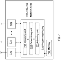
- Figure 7 shows a schematic block diagram of embodiments of a network node 101, 102, 103.
- the network node 101, 102, 103 comprises an obtaining unit 701 , which may also be referred to as a collecting or obtaining device or circuitry.
- the obtaining unit 701 is configured to obtain signal strength values associated with the antennas for a number of user equipments in the wireless telecommunications network 100.
- one antenna of the two antennas serves user equipments in a cell of the network node 101, 102, 103 and the other antenna of the two antennas serves user equipments in a neighboring cell of the same network node 101, 102, 103 or another network node in the wireless telecommunications network 100.
- the signal strength values may be obtained by the network node 101, 102, 103 from user equipments served by the cell of the network node 101, 102, 103, respectively.
- the network node 101, 102, 103 also comprises a determining unit 702 , which may also be referred to as a determining device or circuitry.
- the determining unit 702 is configured to determine an amount of user equipments of the number of user equipments having a signal strength value difference from two antennas that passes a determined threshold for the signal strength value difference.
- the determined signal strength value difference threshold i.e. the geometry factor G
- the determined threshold amount of user equipments i.e. the percentile P
- the percentile P is in the range of about 5-60 percent of the number of user equipments.
- the network node 101, 102, 103 further comprises an adjusting unit 702 , which may also be referred to as an adjuster or an adjusting device or circuitry.
- the controlling unit 702 is configured to adjust at least one antenna parameter of at least one of the two antennas when the determined amount of user equipments passes a determined threshold for the amount of user equipments.
- the at least one antenna parameter is one or more of: the tilt angle of the antenna, the beam width of the antenna, the direction of the antenna, and the null direction of the antenna.
- the determining unit 701 may be configured to adjust the at least one antenna parameter for the one antenna of the two antennas serving user equipments in the cell of the network node 101, 102, 103, for the other antenna of the two antennas that serves user equipments in a neighboring cell of the same 101, 102, 103 or another network node, or for both of the two antennas jointly.
- the determining unit 701 may send the adjusted antenna parameters, i.e. antenna configuration, to the at least one antenna, or to equipment connect to the at least one antenna, or another network node that is positioned at a location closer to the at least one antenna in order to adjust the antenna accordingly.
- the antenna adjustment may be performed as mechanical movements of antenna elements of the at least one antenna or control of phases sent to antenna elements of the at least one antenna.
- the determining unit 701 may be configured to adjust the at least one antenna parameter dependent upon whether the two antennas are positioned at different locations, e.g. located at different network nodes, serving different neighboring cells or co-located at the same network node serving different neighboring cells.
- the at least one antenna parameter when the two antennas are positioned co-located, e.g. at the same network node, serving different neighboring cells, the at least one antenna parameter is one or more of: the beam width of the antenna, and the direction of the antenna.
- the at least one antenna parameter is one or more of: the tilt angle of the antenna, and the null direction of the antenna.
- the determining unit 701 may be configured to adjust the at least one antenna parameter in dependent upon one or more additional measurements, wherein the additional measurements is one of: drop rate measurements of user equipments, and Reference Signal Received Power, RSRP, measurements.
- additional measurements is one of: drop rate measurements of user equipments, and Reference Signal Received Power, RSRP, measurements.
- the network node 101, 102, 103 may also comprise one or more antennas 730, 731, ..., 73N, wherein in N is an integer equal to or larger than two, i.e. N ⁇ 2.
- the one or more antennas 730, 731, ... , 73N may be used for transmitting data information to the served user equipments in the cells for which the one or more antennas 730, 731, ..., 73N, are providing radio coverage.
- the network node 101, 102, 103 may comprise a processing circuitry 710 , which may also be referred to as a processor or a processing unit.
- the processing circuitry 710 may comprise the obtaining unit 701, the determining unit 702 and the adjusting unit 703.
- the embodiments for adjusting antenna parameters of one or more antennas in a wireless telecommunications network 100 may be implemented through one or more processors, such as the processing circuitry 710 in the network node 101, 102, 103 depicted in Figure 7 , together with computer program code for performing the functions and actions of the embodiments herein.
- the program code mentioned above may also be provided as a computer program product, for instance in the form of a data carrier carrying computer program code or code means for performing the embodiments herein when being loaded into the processing circuitry 710 in the network node 101, 102, 103.
- the computer program code may e.g. be provided as pure program code in the network node 101, 102, 103 or on a server and downloaded to the network node 101, 102, 103.
- the network node 101, 102, 103 may further comprise a memory 720 comprising one or more memory units.
- the memory 720 may be arranged to be used to store data, such as, e.g. the geometry factors G and the percentiles P , to perform the methods herein when being executed in the network node 101, 102, 103.
- processing circuitry 710 and the memory 720 described above may refer to a combination of analog and digital circuits, and/or one or more processors configured with software and/or firmware, e.g. stored in a memory, that when executed by the one or more processors such as the processing circuitry 710 perform as described above.
- processors as well as the other digital hardware, may be included in a single application-specific integrated circuit (ASIC), or several processors and various digital hardware may be distributed among several separate components, whether individually packaged or assembled into a system-on-a-chip (SoC).
- ASIC application-specific integrated circuit
- SoC system-on-a-chip
- the common abbreviation "e.g.” which derives from the Latin phrase “exempli gratia,” may be used to introduce or specify a general example or examples of a previously mentioned item, and is not intended to be limiting of such item. If used herein, the common abbreviation “i.e.”, which derives from the Latin phrase “id est,” may be used to specify a particular item from a more general recitation.
- the common abbreviation “etc.”, which derives from the Latin expression “et cetera” meaning “and other things” or “and so on” may have been used herein to indicate that further features, similar to the ones that have just been enumerated, exist.
Claims (20)
- Procédé effectué par un noeud de réseau (102) pour ajuster des paramètres d'une ou plusieurs antennes dans un réseau de télécommunications sans fil (100), le procédé comprenant:l'obtention (201) de valeurs de force de signal associées aux antennes pour un certain nombre d'équipements utilisateurs (121) dans le réseau de télécommunications sans fil (100) ;la détermination (202) d'une quantité d'équipements utilisateurs du nombre d'équipements utilisateurs (121) ayant une différence de valeurs de force de signal de deux antennes qui passent par un seuil déterminé pour la différence de valeurs de force de signal ; etl'ajustement (203) d'au moins un paramètre d'antenne d'au moins l'une des deux antennes lorsque la quantité déterminée d'équipements utilisateurs passe par un seuil déterminé pour la quantité d'équipements d'utilisateurs,caractérisé en ce que le seuil de différence de valeurs de force de signal déterminé se situe dans la plage d'environ 3 à 25 dB et la quantité de seuil déterminé des équipements utilisateurs se situe dans la plage d'environ 5 à 60 pour cent du nombre d'équipements utilisateurs (121).
- Procédé selon la revendication 1, dans lequel une antenne des deux antennes dessert des équipements utilisateurs d'une cellule (205) d'un noeud de réseau (102) et l'autre antenne des deux antennes dessert des équipements utilisateurs d'une cellule voisine (203, 204, 206, 207, 209) du même noeud de réseau ou d'un autre noeud de réseau (101, 102, 103) dans le réseau de télécommunications sans fil (100).
- Procédé selon la revendication 2, dans lequel les valeurs de force de signaux sont obtenues pour des équipements utilisateurs desservis par la cellule (205) du premier noeud de réseau (102).
- Procédé selon la revendication 2 ou 3, dans lequel le au moins un paramètre d'antenne est ajusté pour la première antenne des deux antennes desservant des équipements utilisateurs de la cellule (205) du premier noeud de réseau (102), l'autre antenne des deux antennes dessert des équipements utilisateurs d'une cellule voisine (203, 204, 206, 207, 209) du même noeud de réseau ou d'un autre noeud de réseau (101, 103) ou pour les deux antennes conjointement.
- Procédé selon l'une quelconque des revendications 1 à 4, dans lequel le au moins un paramètre d'antenne est un ou plusieurs des suivants : l'angle d'inclinaison de l'antenne, la largeur de faisceau de l'antenne, la direction de l'antenne et la direction zéro de l'antenne.
- Procédé selon l'une quelconque des revendications 1 à 5, dans lequel le au moins un paramètre d'antenne est ajusté en fonction de celle des deux antennes qui est sont positionnées à des emplacements différents desservant différentes cellules voisines (203, 205, 207, 209) ou positionnées co-localisées pour desservir différentes cellules voisines (204, 206).
- Procédé selon la revendication 6, dans lequel, lorsque les deux antennes sont positionnées co-localisées pour desservir différentes cellules voisines (203,, 207, 209), le au moins un paramètre d'antenne est un ou plusieurs des suivants : la largeur du faisceau d'antenne et la direction d'antenne.
- Procédé selon la revendication 6, dans lequel, lorsque les deux antennes sont positionnées à différents emplacements desservant différentes cellules voisines (203, 206, 207), le au moins un paramètre d'antenne est un ou plusieurs des suivants : l'angle d'inclinaison de l'antenne et la direction zéro de l'antenne.
- Procédé selon l'une quelconque des revendications 1 à 8, dans lequel l'ajustement (203) est en outre réalisé en utilisant une ou plusieurs mesures supplémentaires, dans lequel les mesures supplémentaires sont l'une des suivantes : mesures du taux de chute d'équipements utilisateurs et mesures de puissance reçue du signal de référence RSRP.
- Procédé selon l'une quelconque des revendications 1 à 9, dans lequel le noeud de réseau (102) détermine le au moins un paramètre d'antenne qui doit être ajusté sur la base de différences de valeurs de force de signal du nombre d'équipements utilisateurs (121).
- Noeud de réseau (102) pour ajuster des paramètres d'antenne d'une ou plusieurs antennes dans un réseau de télécommunications sans fil (100), le noeud de réseau (102) comprenant :une circuiterie de traitement (710) configurée pour obtenir des valeurs de force de signal associées aux antennes pour un certain nombre d'équipements utilisateurs (121) dans le réseau de télécommunications sans fil (100), déterminer une quantité d'équipements utilisateurs du nombre d'équipements utilisateurs (121) ayant une différence de valeurs de force de signal de deux antennes qui passe par un seuil déterminé pour la différence de valeurs de force de signal et ajuster le au moins un paramètre d'antenne d'au moins l'une des deux antennes lorsque la quantité déterminée d'équipements utilisateurs passe par un seuil déterminé pour la quantité d'équipements utilisateurs,caractérisé en ce que le seuil de différence de valeurs de force de signal déterminé se situe dans la plage d'environ 3 à 25 dB et la quantité de seuil déterminée d'équipements utilisateurs se situe dans la plage d'environ 5 à 60 pour cent du nombre d'équipements utilisateurs (121).
- Noeud de réseau (102) selon la revendication 11, dans lequel une antenne des deux antennes dessert des équipements utilisateurs d'une cellule (205) du noeud de réseau (102) et l'autre antenne des deux antennes dessert des équipements utilisateurs d'une cellule voisine (203, 204, 206, 207, 209) du même noeud de réseau ou d'un autre noeud de réseau (101, 102, 103) dans le réseau de télécommunications sans fil (100).
- Noeud de réseau (102) selon la revendication 12, dans lequel la circuiterie de traitement (710) est configurée pour obtenir des valeurs de force de signal d'équipements utilisateurs desservis par la cellule (205) du noeud de réseau (102).
- Noeud de réseau (102) selon la revendication 12 ou 13, dans lequel la circuiterie de traitement (710) est configurée pour ajuster le au moins un paramètre d'antenne pour la première antenne des deux antennes desservant les équipements utilisateurs de la cellule (205) du noeud de réseau (102), tandis que l'autre antenne des deux antennes dessert des équipements utilisateurs d'une cellule voisine (203, 204, 206, 207, 209) du même noeud de réseau ou d'un autre noeud de réseau (101, 102, 103) ou pour les deux antennes conjointement.
- Noeud de réseau (102) selon l'une quelconque des revendications 11 à 14, dans lequel le au moins un paramètre d'antenne est un ou plusieurs des suivants : l'angle d'inclinaison de l'antenne, la largeur de faisceau de l'antenne, la direction de l'antenne et la direction zéro de l'antenne.
- Noeud de réseau (102) selon l'une quelconque des revendications 11 à 15, dans lequel la circuiterie de traitement (710) est configurée pour ajuster le au moins un paramètre d'antenne en fonction de celle des deux antennes qui sont positionnées à différents emplacements desservant différentes cellules voisines (203, 207, 209) ou positionnées co-localisées dans le même noeud de réseau (102) desservant différentes cellules voisines (204, 206).
- Noeud de réseau (102) selon la revendication 16, dans lequel, lorsque les deux antennes sont positionnées co-localisées pour desservir différentes cellules voisines (204, 206), le au moins un paramètre d'antenne est un ou plusieurs des suivants : la largeur de faisceau de l'antenne et la direction de l'antenne.
- Noeud de réseau (102) selon la revendication 16, dans lequel, lorsque les deux antennes sont positionnées à différents emplacements desservant différentes cellules voisines (203, 207, 209), le au moins un paramètre d'antenne est un ou plusieurs des suivants : l'angle d'inclinaison de l'antenne et la direction zéro de l'antenne.
- Noeud de réseau (102) selon les revendications 11-18, dans lequel la circuiterie de traitement (710) est configurée pour ajuster le au moins un paramètre d'antenne en fonction d'une ou plusieurs mesures supplémentaires, dans lequel les mesures supplémentaires sont l'une des suivantes : mesures du taux de chute d'équipements utilisateurs et mesures de la puissance reçue du signal de référence RSRP.
- Noeud de réseau (102) selon les revendications 11-19, dans lequel la circuiterie de traitement (710) est configurée pour déterminer le au moins un paramètre d'antenne qui doit être ajusté sur la base de différences de valeurs de force de signal du nombre d'équipements utilisateurs (121).
Applications Claiming Priority (1)
| Application Number | Priority Date | Filing Date | Title |
|---|---|---|---|
| PCT/SE2013/051311 WO2015069159A1 (fr) | 2013-11-07 | 2013-11-07 | Nœud de réseau et procédé de réglage de paramètres d'antenne dans un système de communications sans fil |
Publications (2)
| Publication Number | Publication Date |
|---|---|
| EP3066862A1 EP3066862A1 (fr) | 2016-09-14 |
| EP3066862B1 true EP3066862B1 (fr) | 2017-09-13 |
Family
ID=49627022
Family Applications (1)
| Application Number | Title | Priority Date | Filing Date |
|---|---|---|---|
| EP13795013.5A Active EP3066862B1 (fr) | 2013-11-07 | 2013-11-07 | Noeud de réseau et procédé de réglage de paramètres d'antenne dans un système de communications sans fil |
Country Status (3)
| Country | Link |
|---|---|
| US (1) | US9615265B2 (fr) |
| EP (1) | EP3066862B1 (fr) |
| WO (1) | WO2015069159A1 (fr) |
Cited By (1)
| Publication number | Priority date | Publication date | Assignee | Title |
|---|---|---|---|---|
| CN108966271A (zh) * | 2018-07-23 | 2018-12-07 | 广州视源电子科技股份有限公司 | Wifi模块抗干扰方法、装置、终端设备及存储介质 |
Families Citing this family (14)
| Publication number | Priority date | Publication date | Assignee | Title |
|---|---|---|---|---|
| EP3304966B1 (fr) * | 2015-05-28 | 2020-04-15 | Telefonaktiebolaget LM Ericsson (publ) | Établissement de l'utilité d'unités d'antenne distantes dans un système de communications sans fil |
| US9759799B2 (en) * | 2015-06-24 | 2017-09-12 | International Business Machines Corporation | Beacon array |
| CN106330345B (zh) * | 2015-06-29 | 2020-03-06 | 中兴通讯股份有限公司 | 一种检测电调天线连接线序的方法和装置 |
| US10595322B2 (en) * | 2015-11-23 | 2020-03-17 | Qualcomm Incorporated | Beamforming and user equipment grouping |
| US9907028B1 (en) * | 2016-04-07 | 2018-02-27 | Sprint Communications Company L.P. | Mitigating uplink interference |
| CN106535325A (zh) * | 2016-11-22 | 2017-03-22 | 广东小天才科技有限公司 | 定位方法、信息处理方法、定位装置及信息处理装置 |
| CN108736161B (zh) * | 2017-04-14 | 2021-10-01 | 京东方科技集团股份有限公司 | 移动设备以及移动设备定向天线调节方法 |
| CN108075848A (zh) * | 2018-01-22 | 2018-05-25 | 上海康斐信息技术有限公司 | 一种无线网络控制系统及方法 |
| US11159206B2 (en) * | 2019-03-21 | 2021-10-26 | Telefonaktiebolaget Lm Ericsson (Publ) | Transmission of NR control information in an LTE downlink subframe |
| US10701566B1 (en) * | 2019-06-28 | 2020-06-30 | T-Mobile Usa, Inc. | Multidimensional analysis and network response |
| CN115134882A (zh) * | 2019-09-25 | 2022-09-30 | 华为技术有限公司 | 一种信息传输方法、装置及系统 |
| CN112423398B (zh) * | 2020-11-24 | 2022-07-26 | 新华三技术有限公司 | 无线资源管理的方法、装置、电子设备及介质 |
| CN115134817A (zh) * | 2021-03-29 | 2022-09-30 | 中国移动通信集团山东有限公司 | 5g波束赋形优化方法及系统 |
| US11973548B2 (en) | 2022-02-03 | 2024-04-30 | T-Mobile Usa, Inc. | Adjusting a configuration of a wireless telecommunication network |
Family Cites Families (11)
| Publication number | Priority date | Publication date | Assignee | Title |
|---|---|---|---|---|
| DE19851701C2 (de) | 1998-10-30 | 2000-12-07 | Mannesmann Ag | Interferenzanalyse für ein Mobilfunknetz mit adaptiven Antennen |
| KR100428709B1 (ko) | 2001-08-17 | 2004-04-27 | 한국전자통신연구원 | 다중 경로 정보 피드백을 이용한 순방향 빔형성 장치 및그 방법 |
| GB2378858B (en) * | 2001-08-18 | 2005-07-13 | Motorola Inc | Minimisation of interference in cellular communications systems |
| US7092714B2 (en) | 2002-02-12 | 2006-08-15 | Airnet Communications Corporation | Method for improving RF spectrum efficiency with repeater backhauls |
| FI20030964A0 (fi) | 2003-06-27 | 2003-06-27 | Nokia Corp | Antennisovitusmenetelmä, järjestelmä ja verkkoelementti |
| US8693439B2 (en) * | 2007-09-04 | 2014-04-08 | Nokia Siemens Networks Oy | Reduced ping pong occurrence during handover |
| KR20090074454A (ko) * | 2008-01-02 | 2009-07-07 | 삼성전자주식회사 | 이동통신 단말에서 인접 셀 관리 방법 및 장치 |
| US8774133B2 (en) * | 2008-05-02 | 2014-07-08 | Mediatek Inc. | Method of cell measurement based on cell reselection and measured report in UMTS cellular system |
| US20110212696A1 (en) | 2010-02-26 | 2011-09-01 | Intersil Americas Inc. | System and Method for Reducing In-Band Interference for a Shared Antenna |
| US9226303B2 (en) | 2011-05-10 | 2015-12-29 | Telefonaktiebolaget L M Ericsson (Publ) | Method and arrangement for supporting radio resource management |
| US8494533B2 (en) * | 2011-07-28 | 2013-07-23 | Telefonaktiebolaget L M Ericsson (Publ) | Beamforming for cell edge capacity improvement in a heterogeneous network |
-
2013
- 2013-11-07 US US15/033,499 patent/US9615265B2/en active Active
- 2013-11-07 EP EP13795013.5A patent/EP3066862B1/fr active Active
- 2013-11-07 WO PCT/SE2013/051311 patent/WO2015069159A1/fr active Application Filing
Non-Patent Citations (1)
| Title |
|---|
| None * |
Cited By (2)
| Publication number | Priority date | Publication date | Assignee | Title |
|---|---|---|---|---|
| CN108966271A (zh) * | 2018-07-23 | 2018-12-07 | 广州视源电子科技股份有限公司 | Wifi模块抗干扰方法、装置、终端设备及存储介质 |
| CN108966271B (zh) * | 2018-07-23 | 2021-08-24 | 广州视源电子科技股份有限公司 | Wifi模块抗干扰方法、装置、终端设备及存储介质 |
Also Published As
| Publication number | Publication date |
|---|---|
| US9615265B2 (en) | 2017-04-04 |
| WO2015069159A1 (fr) | 2015-05-14 |
| EP3066862A1 (fr) | 2016-09-14 |
| US20160286407A1 (en) | 2016-09-29 |
Similar Documents
| Publication | Publication Date | Title |
|---|---|---|
| EP3066862B1 (fr) | Noeud de réseau et procédé de réglage de paramètres d'antenne dans un système de communications sans fil | |
| US11476957B2 (en) | Communication system with beam quality measurement | |
| US9408095B2 (en) | Autonomous determination of overlapping coverage in heterogeneous networks | |
| US8498207B2 (en) | Dynamic load balancing | |
| KR20200003197A (ko) | Bwp 내의 참조 신호를 이용하여 rsrq를 측정하는 방법 및 이를 수행하는 단말 | |
| EP3675548B1 (fr) | Dispositif et procédé de commande de formation de faisceau dans un système de communication sans fil | |
| US10327168B2 (en) | Radio network nodes, wireless device, and methods performed therein for communicating in a wireless communication network | |
| US10334452B2 (en) | Apparatus and method for optimizing parameter of antenna in wireless communication system | |
| EP3266145B1 (fr) | Notification de la puissance disponible pour la communication duplex intégrale | |
| WO2015078483A1 (fr) | Procédé et appareil pour combiner des transmissions bidirectionnelles à l'alternat et simultanée dans un relais | |
| EP3016428A1 (fr) | Dispositif et procédé de communication sans fil | |
| CN111130741A (zh) | 通信方法和设备 | |
| WO2018203779A1 (fr) | Changement de cellule dans un système de communication sans fil | |
| CN113840375B (zh) | 用于寻呼的方法和装置 | |
| CN111641964B (zh) | 无线通信方法和设备 | |
| US20230208485A1 (en) | Improvements for beamformed transmissions in wireless communication networks | |
| EP3528528A1 (fr) | Procédé et dispositif de transmission de signal de mesure | |
| CN105850087B (zh) | 用于使用信道互易性降低开销的方法和装置 | |
| CN104038986A (zh) | 处理基地台的选择的方法及其通信装置 | |
| US11984937B2 (en) | Communication system with beam quality measurement | |
| EP4255059A1 (fr) | Procédé, appareil et dispositif de communication sans fil, et support d'enregistrement | |
| EP3925257B1 (fr) | Procédés et dispositifs d'estimation de brouillage intercellulaire | |
| Assefa | ADDIS ABABA INSTITUTE OF TECHNOLOGY SCHOOL OF ELECTRICAL AND COMPUTER ENGINEERING Investigation and Optimization of Electrical Tilt and Azimuth for Addis Ababa LTE Network | |
| JP2014033249A (ja) | 無線通信システムおよび上りリンクリソース割り当て方法 | |
| CN104684059A (zh) | 一种功率控制方法及设备 |
Legal Events
| Date | Code | Title | Description |
|---|---|---|---|
| PUAI | Public reference made under article 153(3) epc to a published international application that has entered the european phase |
Free format text: ORIGINAL CODE: 0009012 |
|
| 17P | Request for examination filed |
Effective date: 20160323 |
|
| AK | Designated contracting states |
Kind code of ref document: A1 Designated state(s): AL AT BE BG CH CY CZ DE DK EE ES FI FR GB GR HR HU IE IS IT LI LT LU LV MC MK MT NL NO PL PT RO RS SE SI SK SM TR |
|
| AX | Request for extension of the european patent |
Extension state: BA ME |
|
| DAX | Request for extension of the european patent (deleted) | ||
| RIC1 | Information provided on ipc code assigned before grant |
Ipc: H04W 16/28 20090101AFI20170526BHEP Ipc: H01Q 1/24 20060101ALI20170526BHEP |
|
| GRAP | Despatch of communication of intention to grant a patent |
Free format text: ORIGINAL CODE: EPIDOSNIGR1 |
|
| GRAS | Grant fee paid |
Free format text: ORIGINAL CODE: EPIDOSNIGR3 |
|
| INTG | Intention to grant announced |
Effective date: 20170710 |
|
| GRAA | (expected) grant |
Free format text: ORIGINAL CODE: 0009210 |
|
| AK | Designated contracting states |
Kind code of ref document: B1 Designated state(s): AL AT BE BG CH CY CZ DE DK EE ES FI FR GB GR HR HU IE IS IT LI LT LU LV MC MK MT NL NO PL PT RO RS SE SI SK SM TR |
|
| REG | Reference to a national code |
Ref country code: GB Ref legal event code: FG4D |
|
| REG | Reference to a national code |
Ref country code: CH Ref legal event code: EP |
|
| REG | Reference to a national code |
Ref country code: IE Ref legal event code: FG4D |
|
| REG | Reference to a national code |
Ref country code: AT Ref legal event code: REF Ref document number: 929309 Country of ref document: AT Kind code of ref document: T Effective date: 20171015 |
|
| REG | Reference to a national code |
Ref country code: DE Ref legal event code: R096 Ref document number: 602013026643 Country of ref document: DE |
|
| REG | Reference to a national code |
Ref country code: FR Ref legal event code: PLFP Year of fee payment: 5 |
|
| REG | Reference to a national code |
Ref country code: NL Ref legal event code: MP Effective date: 20170913 |
|
| REG | Reference to a national code |
Ref country code: LT Ref legal event code: MG4D |
|
| PG25 | Lapsed in a contracting state [announced via postgrant information from national office to epo] |
Ref country code: HR Free format text: LAPSE BECAUSE OF FAILURE TO SUBMIT A TRANSLATION OF THE DESCRIPTION OR TO PAY THE FEE WITHIN THE PRESCRIBED TIME-LIMIT Effective date: 20170913 Ref country code: SE Free format text: LAPSE BECAUSE OF FAILURE TO SUBMIT A TRANSLATION OF THE DESCRIPTION OR TO PAY THE FEE WITHIN THE PRESCRIBED TIME-LIMIT Effective date: 20170913 Ref country code: LT Free format text: LAPSE BECAUSE OF FAILURE TO SUBMIT A TRANSLATION OF THE DESCRIPTION OR TO PAY THE FEE WITHIN THE PRESCRIBED TIME-LIMIT Effective date: 20170913 Ref country code: NO Free format text: LAPSE BECAUSE OF FAILURE TO SUBMIT A TRANSLATION OF THE DESCRIPTION OR TO PAY THE FEE WITHIN THE PRESCRIBED TIME-LIMIT Effective date: 20171213 Ref country code: FI Free format text: LAPSE BECAUSE OF FAILURE TO SUBMIT A TRANSLATION OF THE DESCRIPTION OR TO PAY THE FEE WITHIN THE PRESCRIBED TIME-LIMIT Effective date: 20170913 |
|
| REG | Reference to a national code |
Ref country code: AT Ref legal event code: MK05 Ref document number: 929309 Country of ref document: AT Kind code of ref document: T Effective date: 20170913 |
|
| PG25 | Lapsed in a contracting state [announced via postgrant information from national office to epo] |
Ref country code: RS Free format text: LAPSE BECAUSE OF FAILURE TO SUBMIT A TRANSLATION OF THE DESCRIPTION OR TO PAY THE FEE WITHIN THE PRESCRIBED TIME-LIMIT Effective date: 20170913 Ref country code: GR Free format text: LAPSE BECAUSE OF FAILURE TO SUBMIT A TRANSLATION OF THE DESCRIPTION OR TO PAY THE FEE WITHIN THE PRESCRIBED TIME-LIMIT Effective date: 20171214 Ref country code: LV Free format text: LAPSE BECAUSE OF FAILURE TO SUBMIT A TRANSLATION OF THE DESCRIPTION OR TO PAY THE FEE WITHIN THE PRESCRIBED TIME-LIMIT Effective date: 20170913 Ref country code: ES Free format text: LAPSE BECAUSE OF FAILURE TO SUBMIT A TRANSLATION OF THE DESCRIPTION OR TO PAY THE FEE WITHIN THE PRESCRIBED TIME-LIMIT Effective date: 20170913 Ref country code: BG Free format text: LAPSE BECAUSE OF FAILURE TO SUBMIT A TRANSLATION OF THE DESCRIPTION OR TO PAY THE FEE WITHIN THE PRESCRIBED TIME-LIMIT Effective date: 20171213 |
|
| PG25 | Lapsed in a contracting state [announced via postgrant information from national office to epo] |
Ref country code: NL Free format text: LAPSE BECAUSE OF FAILURE TO SUBMIT A TRANSLATION OF THE DESCRIPTION OR TO PAY THE FEE WITHIN THE PRESCRIBED TIME-LIMIT Effective date: 20170913 |
|
| PG25 | Lapsed in a contracting state [announced via postgrant information from national office to epo] |
Ref country code: PL Free format text: LAPSE BECAUSE OF FAILURE TO SUBMIT A TRANSLATION OF THE DESCRIPTION OR TO PAY THE FEE WITHIN THE PRESCRIBED TIME-LIMIT Effective date: 20170913 Ref country code: CZ Free format text: LAPSE BECAUSE OF FAILURE TO SUBMIT A TRANSLATION OF THE DESCRIPTION OR TO PAY THE FEE WITHIN THE PRESCRIBED TIME-LIMIT Effective date: 20170913 Ref country code: RO Free format text: LAPSE BECAUSE OF FAILURE TO SUBMIT A TRANSLATION OF THE DESCRIPTION OR TO PAY THE FEE WITHIN THE PRESCRIBED TIME-LIMIT Effective date: 20170913 |
|
| PG25 | Lapsed in a contracting state [announced via postgrant information from national office to epo] |
Ref country code: EE Free format text: LAPSE BECAUSE OF FAILURE TO SUBMIT A TRANSLATION OF THE DESCRIPTION OR TO PAY THE FEE WITHIN THE PRESCRIBED TIME-LIMIT Effective date: 20170913 Ref country code: IS Free format text: LAPSE BECAUSE OF FAILURE TO SUBMIT A TRANSLATION OF THE DESCRIPTION OR TO PAY THE FEE WITHIN THE PRESCRIBED TIME-LIMIT Effective date: 20180113 Ref country code: SK Free format text: LAPSE BECAUSE OF FAILURE TO SUBMIT A TRANSLATION OF THE DESCRIPTION OR TO PAY THE FEE WITHIN THE PRESCRIBED TIME-LIMIT Effective date: 20170913 Ref country code: AT Free format text: LAPSE BECAUSE OF FAILURE TO SUBMIT A TRANSLATION OF THE DESCRIPTION OR TO PAY THE FEE WITHIN THE PRESCRIBED TIME-LIMIT Effective date: 20170913 Ref country code: IT Free format text: LAPSE BECAUSE OF FAILURE TO SUBMIT A TRANSLATION OF THE DESCRIPTION OR TO PAY THE FEE WITHIN THE PRESCRIBED TIME-LIMIT Effective date: 20170913 Ref country code: SM Free format text: LAPSE BECAUSE OF FAILURE TO SUBMIT A TRANSLATION OF THE DESCRIPTION OR TO PAY THE FEE WITHIN THE PRESCRIBED TIME-LIMIT Effective date: 20170913 |
|
| REG | Reference to a national code |
Ref country code: DE Ref legal event code: R097 Ref document number: 602013026643 Country of ref document: DE |
|
| PG25 | Lapsed in a contracting state [announced via postgrant information from national office to epo] |
Ref country code: MC Free format text: LAPSE BECAUSE OF FAILURE TO SUBMIT A TRANSLATION OF THE DESCRIPTION OR TO PAY THE FEE WITHIN THE PRESCRIBED TIME-LIMIT Effective date: 20170913 |
|
| PLBE | No opposition filed within time limit |
Free format text: ORIGINAL CODE: 0009261 |
|
| STAA | Information on the status of an ep patent application or granted ep patent |
Free format text: STATUS: NO OPPOSITION FILED WITHIN TIME LIMIT |
|
| PG25 | Lapsed in a contracting state [announced via postgrant information from national office to epo] |
Ref country code: LI Free format text: LAPSE BECAUSE OF NON-PAYMENT OF DUE FEES Effective date: 20171130 Ref country code: CH Free format text: LAPSE BECAUSE OF NON-PAYMENT OF DUE FEES Effective date: 20171130 Ref country code: DK Free format text: LAPSE BECAUSE OF FAILURE TO SUBMIT A TRANSLATION OF THE DESCRIPTION OR TO PAY THE FEE WITHIN THE PRESCRIBED TIME-LIMIT Effective date: 20170913 |
|
| 26N | No opposition filed |
Effective date: 20180614 |
|
| PG25 | Lapsed in a contracting state [announced via postgrant information from national office to epo] |
Ref country code: LU Free format text: LAPSE BECAUSE OF NON-PAYMENT OF DUE FEES Effective date: 20171107 |
|
| REG | Reference to a national code |
Ref country code: BE Ref legal event code: MM Effective date: 20171130 |
|
| REG | Reference to a national code |
Ref country code: IE Ref legal event code: MM4A |
|
| PG25 | Lapsed in a contracting state [announced via postgrant information from national office to epo] |
Ref country code: MT Free format text: LAPSE BECAUSE OF NON-PAYMENT OF DUE FEES Effective date: 20171107 |
|
| PG25 | Lapsed in a contracting state [announced via postgrant information from national office to epo] |
Ref country code: IE Free format text: LAPSE BECAUSE OF NON-PAYMENT OF DUE FEES Effective date: 20171107 |
|
| PG25 | Lapsed in a contracting state [announced via postgrant information from national office to epo] |
Ref country code: BE Free format text: LAPSE BECAUSE OF NON-PAYMENT OF DUE FEES Effective date: 20171130 Ref country code: SI Free format text: LAPSE BECAUSE OF FAILURE TO SUBMIT A TRANSLATION OF THE DESCRIPTION OR TO PAY THE FEE WITHIN THE PRESCRIBED TIME-LIMIT Effective date: 20170913 |
|
| PGFP | Annual fee paid to national office [announced via postgrant information from national office to epo] |
Ref country code: DE Payment date: 20181128 Year of fee payment: 6 |
|
| PG25 | Lapsed in a contracting state [announced via postgrant information from national office to epo] |
Ref country code: HU Free format text: LAPSE BECAUSE OF FAILURE TO SUBMIT A TRANSLATION OF THE DESCRIPTION OR TO PAY THE FEE WITHIN THE PRESCRIBED TIME-LIMIT; INVALID AB INITIO Effective date: 20131107 |
|
| PG25 | Lapsed in a contracting state [announced via postgrant information from national office to epo] |
Ref country code: CY Free format text: LAPSE BECAUSE OF FAILURE TO SUBMIT A TRANSLATION OF THE DESCRIPTION OR TO PAY THE FEE WITHIN THE PRESCRIBED TIME-LIMIT Effective date: 20170913 |
|
| PG25 | Lapsed in a contracting state [announced via postgrant information from national office to epo] |
Ref country code: MK Free format text: LAPSE BECAUSE OF FAILURE TO SUBMIT A TRANSLATION OF THE DESCRIPTION OR TO PAY THE FEE WITHIN THE PRESCRIBED TIME-LIMIT Effective date: 20170913 |
|
| PG25 | Lapsed in a contracting state [announced via postgrant information from national office to epo] |
Ref country code: TR Free format text: LAPSE BECAUSE OF FAILURE TO SUBMIT A TRANSLATION OF THE DESCRIPTION OR TO PAY THE FEE WITHIN THE PRESCRIBED TIME-LIMIT Effective date: 20170913 |
|
| PG25 | Lapsed in a contracting state [announced via postgrant information from national office to epo] |
Ref country code: PT Free format text: LAPSE BECAUSE OF FAILURE TO SUBMIT A TRANSLATION OF THE DESCRIPTION OR TO PAY THE FEE WITHIN THE PRESCRIBED TIME-LIMIT Effective date: 20170913 |
|
| REG | Reference to a national code |
Ref country code: DE Ref legal event code: R119 Ref document number: 602013026643 Country of ref document: DE |
|
| PG25 | Lapsed in a contracting state [announced via postgrant information from national office to epo] |
Ref country code: AL Free format text: LAPSE BECAUSE OF FAILURE TO SUBMIT A TRANSLATION OF THE DESCRIPTION OR TO PAY THE FEE WITHIN THE PRESCRIBED TIME-LIMIT Effective date: 20170913 |
|
| PG25 | Lapsed in a contracting state [announced via postgrant information from national office to epo] |
Ref country code: DE Free format text: LAPSE BECAUSE OF NON-PAYMENT OF DUE FEES Effective date: 20200603 |
|
| REG | Reference to a national code |
Ref country code: GB Ref legal event code: 732E Free format text: REGISTERED BETWEEN 20210617 AND 20210623 |
|
| P01 | Opt-out of the competence of the unified patent court (upc) registered |
Effective date: 20230526 |
|
| PGFP | Annual fee paid to national office [announced via postgrant information from national office to epo] |
Ref country code: FR Payment date: 20230929 Year of fee payment: 11 |
|
| PGFP | Annual fee paid to national office [announced via postgrant information from national office to epo] |
Ref country code: GB Payment date: 20231006 Year of fee payment: 11 |