EP3066743B1 - Charge intelligente de batterie reposant sur un contexte - Google Patents
Charge intelligente de batterie reposant sur un contexte Download PDFInfo
- Publication number
- EP3066743B1 EP3066743B1 EP14808516.0A EP14808516A EP3066743B1 EP 3066743 B1 EP3066743 B1 EP 3066743B1 EP 14808516 A EP14808516 A EP 14808516A EP 3066743 B1 EP3066743 B1 EP 3066743B1
- Authority
- EP
- European Patent Office
- Prior art keywords
- charging
- charge
- battery
- electronic device
- parameters
- Prior art date
- Legal status (The legal status is an assumption and is not a legal conclusion. Google has not performed a legal analysis and makes no representation as to the accuracy of the status listed.)
- Not-in-force
Links
Images


Classifications
-
- H—ELECTRICITY
- H02—GENERATION; CONVERSION OR DISTRIBUTION OF ELECTRIC POWER
- H02J—CIRCUIT ARRANGEMENTS OR SYSTEMS FOR SUPPLYING OR DISTRIBUTING ELECTRIC POWER; SYSTEMS FOR STORING ELECTRIC ENERGY
- H02J7/00—Circuit arrangements for charging or depolarising batteries or for supplying loads from batteries
- H02J7/007—Regulation of charging or discharging current or voltage
- H02J7/00712—Regulation of charging or discharging current or voltage the cycle being controlled or terminated in response to electric parameters
-
- H—ELECTRICITY
- H02—GENERATION; CONVERSION OR DISTRIBUTION OF ELECTRIC POWER
- H02J—CIRCUIT ARRANGEMENTS OR SYSTEMS FOR SUPPLYING OR DISTRIBUTING ELECTRIC POWER; SYSTEMS FOR STORING ELECTRIC ENERGY
- H02J7/00—Circuit arrangements for charging or depolarising batteries or for supplying loads from batteries
- H02J7/02—Circuit arrangements for charging or depolarising batteries or for supplying loads from batteries for charging batteries from ac mains by converters
- H02J7/04—Regulation of charging current or voltage
-
- H—ELECTRICITY
- H01—ELECTRIC ELEMENTS
- H01M—PROCESSES OR MEANS, e.g. BATTERIES, FOR THE DIRECT CONVERSION OF CHEMICAL ENERGY INTO ELECTRICAL ENERGY
- H01M10/00—Secondary cells; Manufacture thereof
- H01M10/42—Methods or arrangements for servicing or maintenance of secondary cells or secondary half-cells
- H01M10/425—Structural combination with electronic components, e.g. electronic circuits integrated to the outside of the casing
- H01M10/4257—Smart batteries, e.g. electronic circuits inside the housing of the cells or batteries
-
- H—ELECTRICITY
- H02—GENERATION; CONVERSION OR DISTRIBUTION OF ELECTRIC POWER
- H02J—CIRCUIT ARRANGEMENTS OR SYSTEMS FOR SUPPLYING OR DISTRIBUTING ELECTRIC POWER; SYSTEMS FOR STORING ELECTRIC ENERGY
- H02J7/00—Circuit arrangements for charging or depolarising batteries or for supplying loads from batteries
- H02J7/007—Regulation of charging or discharging current or voltage
- H02J7/00712—Regulation of charging or discharging current or voltage the cycle being controlled or terminated in response to electric parameters
- H02J7/007182—Regulation of charging or discharging current or voltage the cycle being controlled or terminated in response to electric parameters in response to battery voltage
- H02J7/007184—Regulation of charging or discharging current or voltage the cycle being controlled or terminated in response to electric parameters in response to battery voltage in response to battery voltage gradient
-
- Y—GENERAL TAGGING OF NEW TECHNOLOGICAL DEVELOPMENTS; GENERAL TAGGING OF CROSS-SECTIONAL TECHNOLOGIES SPANNING OVER SEVERAL SECTIONS OF THE IPC; TECHNICAL SUBJECTS COVERED BY FORMER USPC CROSS-REFERENCE ART COLLECTIONS [XRACs] AND DIGESTS
- Y02—TECHNOLOGIES OR APPLICATIONS FOR MITIGATION OR ADAPTATION AGAINST CLIMATE CHANGE
- Y02E—REDUCTION OF GREENHOUSE GAS [GHG] EMISSIONS, RELATED TO ENERGY GENERATION, TRANSMISSION OR DISTRIBUTION
- Y02E60/00—Enabling technologies; Technologies with a potential or indirect contribution to GHG emissions mitigation
- Y02E60/10—Energy storage using batteries
Definitions
- the disclosure relates to battery charging, and in particular, to intelligent context based battery charging.
- portable electronic devices are becoming increasingly popular. For example, consumers prefer mobile phones and laptops over traditional telephones and desktop computers. The popularity of tablet personal computers, portable media players, and handheld videogame consoles are also on the rise. A commonality between all these portable electronic devices is that they include one or more rechargeable batteries (e.g., a nickel-cadmium (Ni-Cad) battery or a lithium-ion (Li+)) as a power source.
- rechargeable batteries e.g., a nickel-cadmium (Ni-Cad) battery or a lithium-ion (Li+)
- rechargeable batteries degrade in charge capacity as a byproduct of the charge and discharge cycles. This degradation effect is cumulative and is highly accelerated by fast charge and discharge rates. While the discharge rate is heavily dependent on the usage of the device, the charge rate is typically controlled by the manufacturer during the design of the device. A manufacturer can set the charge rate to a slow charge rate to improve the longevity of the battery. This can be important for devices with embedded batteries that are not removable or replaceable. However, a slow charge rate results in a longer recharge times. Long recharge times equate to a long period of time that the consumer must remain near a power source, which can be undesirable to a consumer who is on the move. Thus, there is a need for improved charging techniques for rechargeable batteries.
- US 2012/299554 describes a method for providing battery management for a device.
- context information is accessed by an electronic device.
- the context information may describe one or more usage patterns of the electronic device.
- a prediction of a charging duration is generated based on the context information, for example.
- Charging parameters may be determined based on the charging duration, where the charging parameters are used to charge a battery of the electronic device.
- a battery charger may be configured with the charging parameters to charge a battery.
- the disclosure includes a method comprising accessing, by an electronic device, context information describing one or more usage patterns of the electronic device, predicting, by the electronic device, a charging duration based on the context information, determining, by the electronic device, charging parameters based on the charging duration, wherein the charging parameters are used to charge a battery of the electronic device, and configuring a battery charger with the charging parameters to charge the battery.
- the predicting comprises generating a model establishing relations between data elements of the context information and the charging duration.
- the predicting further comprises storing the context information as charge history data and comparing the charge history data to a current context information to predict said charging duration.
- the model is generated dynamically.
- the model classifies past context information and current context elements into a discrete number of charging durations.
- the charging parameters comprise a charge current and a float voltage.
- the context information comprises measured parameters and prescriptive parameters
- the method further comprising receiving the charging duration, the measured parameters, and the prescriptive parameters in a charging application and mapping the charging duration to the charging parameters based on the measured parameters and the prescriptive parameters.
- the context information comprises a charge status, charge time, a location, a charge source, and a battery level.
- the disclosure includes an electronic device comprising a battery charger, a battery, one or more processors, and a non-transitory computer readable medium having stored thereon one or more instructions, which when executed by the one or more processors, causes the one or more processors to perform certain techniques described herein, including access context information describing one or more usage patterns of the electronic device, predict a charging duration based on the context information, determine charging parameters based on the charging duration, wherein the charging parameters are used to charge the battery of the electronic device, and configure the battery charger with the charging parameters to charge the battery.
- the disclosure includes a non-transitory computer readable medium having stored thereon one or more instructions, which when executed by one or more processor, causes the one or more processors to perform certain techniques described herein, including access context information describing one or more usage patterns of the electronic device, predict a charging duration based on the context information, determine charging parameters based on the charging duration, wherein the charging parameters are used to charge the battery of the electronic device, and configure the battery charger with the charging parameters to charge the battery.
- aspects of the disclosure include systems and methods for context based battery charging.
- context information about usage patterns of an electronic device is used to customize charging a rechargeable battery.
- a predictive engine accesses context information and generates a predicted charge duration.
- a charging application customizes charging parameters in a battery charger based on the predicted charge duration.
- the charging application may generate suggestions to a user to improve battery charging.
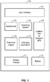
- Fig. 1 illustrates an electronic device 100 including intelligent battery charging according to one aspect.
- Electronic device 100 may be a mobile phone (e.g., a smartphone), a tablet computer, or any other electronic device including a rechargable battery 110 as a power source, for example.
- electronic device 100 includes a user interface 101 for receiving user inputs and providing outputs.
- Interface 101 may be a single component, such as a touchscreen, or multiple components such as a display and keyboard, for example.
- Electronic device 100 may include system hardware (HW), such as one or more microprocessors and/or controllers, sensors, and a location system such as hardware and/or software for a global positioning system (GPS), for example, which are collectively denoted as 130 in Fig. 1 .
- Electronic device 100 may further include an operating system 102 and applications 103.
- Applications 103 may include a wide variety of programs that may be loaded on device 100 by a user to perform a wide range of user specific functions (e.g., "Apps"
- Context information may include application data (e.g., an appointment on a calendar), operating system data (e.g., date and time), GPS data (location of the device), and other information about a particular user's device usage patterns.
- a charging application 112 and/or predictive engine 120 sends and/or receives information to/from user interface 101, operating system 102, one or more applications 103 and/or other system HW & sensors or GPS 130 to configure a battery charger 111 to charge a battery 110 to optimize charging around usage patterns of electronic device 100, for example.
- predictive engine 120 may receive information including, but not limited to, calendar information from a calendaring application, time and date information from operating system 102, a battery charge information (e.g., a state of charge a.k.a charge level) from battery charger 111, location information (e.g., from a GPS). Predictive engine 120 may use the received information to create a model pertaining to the user's charging patterns and produce a predicted duration for a charge.
- charging application 112 may receive information including, but not limited to, charging parameters from battery charger 111, one or more predictions from prediction engine 120, application information, and hardware or operating system information, to customize charging parameters in battery charger 111 or generate suggestions to a user through interface 101, for example.
- Predictive engine 120 and/or charging application 112 may store the information as charging history information to improve predictions (by predictive engine 120) and/or suggestions (by charging algorithm 112).
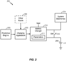
- a battery charger 210 has an input coupled to an external power source to receive a voltage, Vext.
- Battery charger 210 may provide power to system electronics 201 and rechargeable battery 250, which in this example is a lithium ion battery (Li+).
- a switch (SW) 212 may allow battery 250 to provide power to system electronics 201 when the external power source is disconnected, for example.
- Battery charger 210 may be part of a single power management integrated circuit (PMIC) or provided as a separate circuit.
- PMIC power management integrated circuit
- Battery charger 210 is configured with charge parameters 211 to produce voltage and current to charge battery 250.
- charging application 220 receives information from predictive engine 230 and information from other inputs 240 (e.g., applications, OS, system HW).
- Charging application 220 customizes the charge parameters 211 in battery charger 210 to improve charging based on inputs from the predictive engine 230 and optionally other inputs 240, for example.
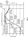
- Fig. 3 shows an example battery charging plot illustrating configurable parameters of a battery charger according to one aspect.
- the plot in Fig. 3 includes three curves: battery voltage curve 301, input current curve 302, and charge current curve 303.
- the battery charge cycle may start with a deeply depleted battery having a very low voltage (e.g., Vbatt ⁇ 2v).
- Ichg 10mA
- the battery voltage Vbatt will increase to a trickle charge to pre-charge transition voltage, which is fixed at 2v in this example but could be programmable in other aspects.
- the charger When the charger is in pre-charge mode, it may produce a programmable pre-charge current into the battery until Vbatt increases to a pre-charge to fast charge transition, which may be programmable. After transitioning to fast charge mode, the battery charger may produce a programmable fast charge current to the battery. In this example, the fast charge current is constant, but in other aspects the fast charge current may initially be set at a maximum level and reduced as Vbatt increases, for example. During fast charging, Vbatt continues to increase. When Vbatt increases to a threshold, which is also programmable, the battery charger may transition from current controlled charging to voltage controlled charging. In this example, the battery charger transitions to constant voltage charging when Vbatt is equal to a programmed float voltage value, Vfloat.
- Vfloat a programmed float voltage value
- a programmable threshold triggering a transition from controlled current charging to controlled voltage charging may be different (e.g., greater than) a programmable float voltage used during controlled voltage charging. Charging may terminate when the charge current in voltage control mode drops below a programmable value, for example.
- charging parameters 211 may be modified by charging application 220 to optimize battery charging (e.g., longer battery life or shorter charge time).
- predictive engine 230 may output different predicted charging durations to charging application 220, and application 220 may change the parameters controlling the pre-charge to fast charge transition, charge current, and/or float voltage, for example, based on the predicted charging duration.
- the pre-charge to fast charge voltage transition indicates how soon the battery charger starts fast charging as Vbatt increases. If the battery charger starts fast charging sooner (i.e., at lower values of Vbatt), it can reduce charge times, but this also reduces battery life.
- charging application 220 may make analogous changes to the charging parameters 211 based on other inputs as described in more detail below.
- Fig. 4A illustrates an example predictive engine 410 according to another aspect.
- Certain aspects of the disclosure may access and store user specific information about historical context data to generate predictions used to optimize charging of a battery.
- predictive engine 410 receives context information about an electronic device's use patterns relevant to charging a battery.
- Some optional context information that may be advantageous for battery charging may include a charge status 401 (e.g., notify predictive engine when charging stars and stops), battery level 402, time and/or date 403, GPS location and/or motion 404, charge source 405 (e.g., AC adapter or Universal Serial Bus (USB) port), and optionally other input data 406.
- Predictive engine 410 comprises a data capture component 411, model generation component 413, and predictor component 415.
- Data capture component 411 receives the context information and stores the context information as charging history data 412 (e.g., in a memory of the electronic device).
- Charging history data 412 may include data of each particular charging activity including a day of the week (e.g., Sun, Mon, ..., Fri, Sat), time (e.g., hour and/or minute a charge was initiated), a period of the day (morning, afternoon, evening) a charge was initiated, initial battery levels, duration (e.g., bucketed into defined durations such as ⁇ 30min, ⁇ 60min, ⁇ 90min, or > 90min), location and/or motion (e.g., latitude/longitude or even cell ID), source type (AC or USB), and a last charge time, for example.
- a day of the week e.g., Sun, Mon, ..., Fri, Sat
- time e.g., hour and/or minute a charge was initiated
- a period of the day morning, afternoon, evening
- sensors such as GPS, an accelerometer, or gyroscope may also provide motion of the user to determine further context information (e.g., driving to work, stationary in the office or at home, etc).
- time may advantageously be expressed in hour of the day and period of the day and classified as follows: a. Early Morning: 5am-8am b. Morning: 8-12am c. Afternoon: 12am-5pm d. Evening: 5pm-8pm e. Late Evening: 8pm-12pm f. Night: 12pm-5am.
- Model generation component 413 receives charging history data 412 and current context information from data capture component 411 and produces and/or updates a model that establishes relations between data elements of context information (e.g., time, location, etc%) and charge duration.
- the model may indicate what particular data elements in the context information impact a predicted charge duration, for example.
- Predictor 415 receives a persisted model 414 and current context information. Predictor 415 analyzes the current context information and compares the current context information to persisted model 414 to produce predicted charge durations, for example.
- a predicted charge duration may be a predicted amount of time a user is expected to charge the battery under current conditions (i.e., current context).
- predictive engine 410 may output a particular time when a user is predicted to perform a charging operation (e.g., when a user is predicted to plug the phone into a wall adapter).
- Aspects of the disclosure may use classifiers and classification techniques to receive and process context information and generate and analyze models to produce predicted charge durations, for example. Some aspects may use classification, prediction, and modeling techniques described in U.S. Patent Application Publication No. US 2013/0238540 A1 , Application Serial No. 13/602,250, filed September 3, 2012 , entitled "Method and Apparatus for Improving a User Experience or Device Performance Using an Enriched User Profile," the contents of which are hereby incorporated herein by reference in its entirety.
- Fig. 4B illustrates dynamic models according to another aspect.
- Features and advantages of the disclosure include generating models dynamically based on input data, such as features.
- Fig. 4B illustrates feature data, including time data 440, day of week (DOW) 441, time since last charge 442, predicted time to next charge 443, charger type 444, location 445, battery level 446, and/or other features, for example.
- Each feature may have multiple different data values, as illustrated by data points such as 490.
- Predictive engine 430 may use the data features to generate models, such as models 450-452. Models are generated based on historic and current input feature data to discrete outputs.
- models classify an input data set to one of three outputs corresponding to predicted charge times: charge for less than 30 minutes (charge ⁇ 30 min), charge for between 30 minutes and 60 minutes (30 min ⁇ charge ⁇ 60 min), and charge for more than 60 minutes (charge > 60 min).
- charge ⁇ 30 min charge for less than 30 minutes
- charge for between 30 minutes and 60 minutes 30 min ⁇ charge ⁇ 60 min
- charge for more than 60 minutes charge > 60 min.
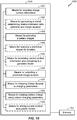
- Fig. 5 illustrates an example method of intelligent battery charging in an electronic device according to one aspect.
- charge context information may be received in predictive engine.
- context information may include time, date, battery level, location/motion, charge source (e.g., AC adapter or USB port), or charge status (e.g., charging/not charging).
- the context information may be stored as part of a charging history as described above.
- a model is optionally generated to establish relations between data elements in the context information and charge duration.
- a battery charger in the electronic device is activated. For example, a user may plug a mobile phone into a wall adapter or USB port, which may activate charging.
- a charging application may send a query to a predictive engine for a charging duration (e.g., how long does the predictive engine believe this charging will last under present circumstances?).
- the predictive engine may access current context information and compare the current context to a persisted model at 505. For example, the predictive engine may access the current date, time, location/motion, battery level, charge source, and other system data and determine, using the persisted model, a likely charging duration for the present charging operation.
- Predicted charge durations may be provided in one of a number of "buckets.” For example, predicted charge durations less than 15 minutes may be placed in a "10 minute” bucket, predicted charge durations between 15 minutes and 45 minutes may be placed in a “30 minute bucket,” predictions between 45 minutes and 1.5 hours may be placed in a “1 hour bucket,” predictions between 1.5 and 2.5 hours may be placed in a “2 hour bucket,” and predictions greater than 2.5 hours may be placed in a “greater than 3 hour bucket.”
- the predicted charge duration is output to the charging application.
- the charging application maps the predicted charge duration to charging parameters, which may be set in a battery charger.
- a lookup table may be used to determine particular charge current parameters, float voltage parameters, or other parameters to increase the battery level the maximum amount possible within the predicted charge time.
- a lookup table may be used to determine particular charge current parameters, float voltage parameters, or other parameters to increase the battery level at a slow rate over the predicted charge time to maximize battery life.
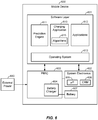
- a mobile device 600 such as a table computer or smartphone, may include a charging application 610 that receives inputs from a predictive engine 611 and applications 612. Predictive engine 611 is optional in this example.
- Charging application 610 runs on a software layer 601 and may communicate with hardware, including system electronics 602 and a power management integrated circuit (PMIC) 603 through operating system 613 and/or communication buses, such as an I2C bus, for example.
- PMIC power management integrated circuit
- Charging application 610, predictive engine 611, applications 612 and operating system 613 may be stored in a non-transitory computer readable medium (CRM) 606 such as memory (e.g., RAM, ROM, non-volatile memory) and executed by one or more processors (e.g., microprocessors, ⁇ P) 605.
- CRM computer readable medium
- a non-transitory computer readable medium may store one or more instructions and/or programs, which when executed by the one or more processors, causes the one or more processors to perform the operations described herein.
- Charging application 610 may configure a battery charger 604, which is shown in this example as part of PMIC 603, but could be a standalone IC.
- Charging application 610 may receive data inputs from applications and optionally a predictive engine to configure battery charger 604, for example. In this example, charging application may send and receive signals to a user interface (not shown) to further tailor the battery charging process.
- charging application 610 generates suggestions to a user to improve battery charging.
- Suggestions can be instructions or directions provided by charging application 100 to direct a user of the electronic device to perform an action, for example.
- the action can improve the charge performance of the battery when performed by the user.
- charging application 610 provides a suggestion when it detects that a battery is nearly depleted.
- the suggestion can direct the user to a nearby power source such a wall outlet.
- charging application 610 can detect the geolocation of the electronic device using a location unit and identify one or more power sources that are nearby the detected geolocation from a registry of power sources available to the charging application, for example.
- the one or more power sources can be provided to the user as a suggestion of places to charge the electronic device. This suggestion can assist the user in locating a wall outlet to plug in an AC/DC adapter for charging the electronic device.
- charging application 610 can provide a suggestion when a current charging rate is less than desirable.
- the suggestion can be to locate another power source capable of providing a desirable charging rate.
- the electronic device can be plugged into a USB port of a personal computer that is providing a charging rate that is less than a desired charging rate.
- the USB port is charging the battery too slowly.
- Charging application 610 detects the inadequate charging rate and generates a suggestion of a nearby wall outlet capable of providing a more optimal charging rate (e.g., a charging rate that is closer to the maximum charging rate).
- the suggestion can be "Use AC/DC adapter instead of PC USB port for optimal charging at this time.”
- charging application 610 can provide a suggestion to disable certain functionality or close particular applications on the electronic device when the current charging rate is less than desirable. Performing the suggestion can decrease the discharge rate of the electronic device, thereby shortening the period of time that is necessary to fully charge the battery. Depending on the charging rate, the amount of power needed to fully charge the battery, and/or the period of time that is allocated to charging the battery (e.g., a duration from predictive engine 611), charging application 610 can determine whether the battery can be fully charged in the allocated period of time. If the battery cannot be fully charged in the allocated period of time, charging application 610 can generate a suggestion that the user disable features or functionality of the device.
- a suggestion can be "Please turn off a radio feature of the device for fastest charging.”
- the suggestion can be "Please turn off the display of the device for fastest charging.”
- the suggestion can be "Please turn off the electronic device for fastest charging.”
- charging application 610 can first provide a suggestion to locate another power source. If the charge rate is still insufficient after recommending the other power source, charging application 610 can then provide a suggestion to disable functionality or close applications of the electronic device.
- charging application 610 can also provide a suggestion to disable certain functionality or close a particular application on the electronic device when the thermal loads in the electronic device are higher than a maximum value.
- the maximum value can be set by the manufacturer.
- Thermal loads in mobile devices can originate primarily from three main sources.
- the first source is the processors of the electronic device which can include an application processor to manage applications and a baseband processor to manage radio functionality of the electronic device which includes making calls or transferring data.
- the second source is the RF power amplifier which enables the electronic device to transmit voice and data signals to a base station tower to route a telephone call or internet address. Typically the power amplifier uses the greatest battery power and thus dissipates the most heat.
- the third source is the battery charger which charges the battery.
- each component of the electronic device can specify a maximum thermal load. When the maximum thermal load of a component is exceeded, the component can perform sub optimally or can be damaged.
- the maximum thermal loads (of the electronic device as a whole or the components of the electronic device) and the current thermal loads can be received as part of the inputs of charging application 610.
- charging application 610 can output a desired charging state. The desired charging state can be throttled back as to not overload the thermal loads of the electronic device since the battery charger dissipates a large amount of heat.
- Charging application 610 can also provide a suggestion to disable certain functionality or close particular applications when the current thermal loads are too high. Disabling other functionality can reduce the overall thermal loads in the electronic device. When the overall thermal loads in the electronic device decreases, the desired charging state can be readjusted to account for the decrease in overall thermal load. For example, a suggestion can be "Device is too hot. Please turn off device for fastest charging.”
- Charging application 610 can also access information related to charging the battery. For example, such data can include the number of times the battery has been charged, the manner in which the battery has been charged (e.g., charging rate), and the condition of the battery (which includes its ability to hold charge, thermals, life expectancy, etc.). This data can also be outputted by charging application 610 for analysis by another system, such as the predictive engine.
- Charging application 610 includes one or more charging algorithms 615.
- Charging algorithm 615 can process context information received by charging application 610 into a desired charging state (or desired charging rate), and/or suggestions.
- the context information received by one or more algorithms can fall into three categories: prescriptive parameters, measured parameters, and predictive parameters.
- One or more parameters from one or more categories can be analyzed by charging algorithms 615 to determine the desired charging state, desired charging rate, and/or suggestions, for example.
- Prescriptive parameters are static parameters that are prescribed by the user or the manufacturer to tune the performance of the electronic device and more particularly the performance of the battery charger. Prescriptive parameters can include attributes of the battery charger, battery, or other components within the electronic device. Prescriptive parameters may be static parameters, which may not be based on feedback or measurements from the electronic device, and thus may not dynamically change while the electronic device is turned on unless instructed by the user.
- a prescriptive parameter can be a factory hardware preset notifying charging algorithm 615 of hardware characteristics of the electronic device.
- the hardware preset can be a configuration setting of whether the electronic device uses an embedded or replaceable battery. Devices with an embedded battery can be more sensitive to shortened battery cycle life since the battery is not easily replaced. As a result, charging algorithm 615 can tune the performance of the battery charger to improve battery cycle life.
- the hardware preset can be an identifier associated with the type of battery installed in the device or the type of battery charger installed within the device. The type of battery and/or the type of battery charger can limit the desired charging states that can be applied.
- a Lithium Ion (Li+) battery can be configured for slow, medium, and fast charging, while a Ni-Cad battery can only be configured for slow or medium charging.
- the type of battery charger installed in the device can specify what charging rates are available.
- the hardware preset can be a battery capacity value or battery identifier associated with the battery.
- the hardware preset can be a maximum thermal load for the electronic device as a whole or for a component of the electronic device. For instance, the maximum thermal load of the battery can be specified. Exceeding the maximum thermal load of the battery can damage the battery thus resulting in shorter battery cycle life or charge performance.
- a user generated prescriptive parameter may be a user profile.
- the user profile can include a charging profile out of a set of available charging profiles.
- a charging profile is a holistic description of how the electronic device should be charged. The holistic description can balance a variety of factors including charging performance (e.g., charging time), thermal load, and battery life. These factors are related to one another and therefore a charging profile describes the importance (or weighting) for each of these factors. Depending on factors such as how a user intends to use the device or how often the device is to be replaced, a charging profile can be preferred over another.
- a mobile device may have a wide range of end consumers, and therefore, a manufacturer can include a variety of charging profiles to tailor the charging performance of the smartphone to a particular end consumer. For instance, a businessman can use his smartphone for business tasks (emails, scheduling, applications, etc.). Furthermore, the smartphone can be replaced every six months since it is part of corporate policy. Given that the businessman cares little for battery cycle life since the device is replaced frequently, a "power user" charging profile can be selected. The "power user" charging profile can ignore the importance of battery life cycle in exchange for faster charging performance. In contrast, a casual user of the smartphone may periodically check email and call family, but does not always need a full charge and rarely upgrades the phone.
- a "causal user” charging profile can be selected.
- the “casual user” charging profile can place the importance on improved battery cycle life in exchange for slow charge performance, for example.
- exceptions can also be added to a given charging profile to further fine tune the charging performance of the electronic device. Exceptions can be attached to a given charging profile. In the example above, the businessman may find discomfort in holding a hot phone next to his face. As a result, an exception can be added to the "power user" charging profile where the charging performance should be throttled back when the user is making a voice call without a Bluetooth headset and the battery is charging, for example.
- Measured parameters are parameters based on the past and/or present environment of the electronic device.
- the measured parameters can be measurements that are dynamically taken from the electronic device. These measurements can be used to dynamically update the charging behavior according to the past and/or present environment, thus allowing the charging application 610 to tune the battery charging according to available resources and past and present conditions, for example.
- a measured parameter can be properties of the battery.
- the battery temperature, condition, and age can be dynamically determined and transmitted to charging application 610.
- Charging algorithm 615 can consider the optimal charging rate given the temperature, condition, or age of the battery. For instance, a battery may not charge well when it is hot and thus charging algorithm 615 can take into consideration the battery temperature when determining a desired charging state.
- a measured parameter can be the available power source.
- the electronic device can sense what power source is currently be used to charge the electronic device (e.g., USB or AC) and relay this information to charging application 610.
- Charging algorithm 615 can determine a desired charging state based on the power source. For example, if the power source is a USB port, charging algorithm 615 can determine the limitations of the power source and adjust the desired charging state accordingly.
- the measured parameter can be the thermal loads in the electronic device.
- the thermal loads can be determined by a thermal measurement unit of the electronic device.
- the thermal measurement unit can measure the thermal load of the electronic device or a component of the electronic device.
- Charging algorithm 615 can compare the measured thermal load with prescriptive parameters that describe the maximum thermal load of a component within the electronic device (such as battery, battery charger, processors, power amplifier, etc.) or the thermal load of the electronic device as a whole. Charging algorithm 615 can consider the effect changing the charging rate will have on the thermal load when it provides a desired charging state.
- the measured parameter can be the geolocation of the electronic device.
- the geolocation can be determined by a location tracking unit of the electronic device, such as a GPS, for example.
- Charging algorithm 615 can compare the geolocation against a plurality of saved locations, such as home, office, travel, gym, etc. If a match occurs, charging algorithm can adjust the charging behavior accordingly. For example, an electronic device that is at home is likely to stay plugged into the power source for an extended period of time. In contrast, an electronic device that is in the office may be more likely to be plugged in sporadically as the user goes from meeting to meeting. Charging algorithm 615 can consider these factors when determining the desired charging state or suggestions.
- Predictive parameters are parameters that may be derived by a predictive analysis engine or a charging application.
- a predictive analysis engine may predict charge duration or times charging may occur by analyzing measurements and behavior of the electronic device to deduce usage patterns.
- charging application 610 may access (e.g., snoop) other applications on the electronic device to discover information about the user, such as the user's schedule. For instance, charging application 610 may retrieve calendar appointments from a calendar application. Similarly, charging application 610 determine that the typical work hours and sleep hours of the user by analyzing the usage of the electronic device.
- charging application 610 may output a predicted schedule for the user based on the usage patterns.
- the predicted schedule can predict the user's weekly or daily patterns. This can include predicting periods of activity/inactivity, the location of the electronic device throughout the day (e.g., will be in the office at 2pm today), and the urgency of having the electronic device sufficiently powered to perform a task.
- predictive analysis engine 611 may predict a charging duration as described above, where an electronic device that is plugged in for charging at 11pm will remain plugged in until 6am the next day based on a consistent pattern of device inactivity between the hours of 11pm and 6am. These periods of inactivity (or even periods of activity) can be derived from usage patterns and be used by the predictive analysis engine to better predict the future charging durations of the electronic device.
- charging application 610 may determine that the electronic device will not be plugged in for the next five hours based on calendar appointments retrieved from a calendar application. This information can be processed by charging application 610 so that charging algorithm 615 can factor that into consideration when generating the desired charging state and suggestions, for example.
- charging application 610 may determine that the user of the electronic device will be on a train for the next two hours and that this overlaps with telephone appointments. Given that the user will likely have to make calls while on the train, charging application 610 may generate an urgent notification to have the electronic device sufficiently charged to make these calls. Charging algorithm 615 can detect this urgent notification and provide suggestions to the user that help ensure the device is properly charged before the user boards the train.
- Fig. 7 illustrates a charging system according to another aspect.
- Charging system 700 includes electronic device 701, electronic device 702, network 720 (e.g., including the Internet and/or a wireless network), and server 710.
- Electronic device 701 and electronic device 702 can be similar or substantially similar to electronic device 600 of Fig. 6 , for example.
- Local charging data is transmitted from electronic device 701 and electronic device 702 through network 720 to server 710.
- Server 710 can analyze the local charging data received from the electronic devices to determine whether the charging performance of the electronic devices can be improved.
- charging profiles e.g., slow charge, medium charge, fast charge
- These charging profiles are based on estimated performance calculations of the battery and battery charger.
- Server 710 can analyze the actual performance of the battery and battery charger to determine if the charging profiles should be updated to improve battery performance. If it is determined that battery performance of a charging profile can be improved, the charging profile can be updated. Local parameters that can be combined to provide better service to the user include: performance of battery as new data is collected and the performance of other chargers deployed in the market. Server 710 can then transmit the updated charging profile to electronic devices 701 and 702 via network 720.
- Fig. 8 illustrates a charging algorithm according to one example aspect.
- Charging algorithm 800 can be a part of charging algorithm 615 of Fig. 6 , for example.
- the example flow chart in Fig. 8 illustrates one optional example technique for using prescriptive, measured, and predicted parameters and is to be understood as illustrative a not limiting of the aspects described herein.
- a charging application may access prescribed parameters, such as a user profile, to determine if the user is a power user or casual user (e.g., or another one of potentially many other classifications). If the user is a power user, the process implements aggressive charging to minimize charge time and proceeds to 810. If the user is a casual user, for example, the process may implement conservative to extend battery life and proceed to 815.
- the charging application may evaluate measured parameters at 810, such as battery age, for example. If the battery is new, then it may be more susceptible to fast charging. However, if the battery is old, it may be desirable to extend battery life by slowing down the charge process. Predictive charging is illustrated at 820, 825, 840, and 845. For a new battery, charging during a busy day (820/840), a predicted charging duration may be short, which may cause charging application to configure the battery charger for a fast charge. If the day is less busy, a predicted charging duration may be in an intermediate bucket, and a medium charge may be performed. For night time, a predicted charge may be in a longer duration bucket, and a slow charge may be performed, for example.
- measured parameters such as battery age, for example. If the battery is new, then it may be more susceptible to fast charging. However, if the battery is old, it may be desirable to extend battery life by slowing down the charge process.
- Predictive charging is illustrated at 820, 825, 840, and 845.
- a received duration from the predictive engine may be combined in a charging algorithm with battery age, where durations are mapped to different charging parameters based on an age of the battery, for example.
- charging durations from a predictive engine may be mapped to a wide variety of charging parameters based on other measured parameters, for example.
- a conservative profile produces a similar process as illustrated at 815, 830, 835, 850, and 855.
- predicted charge durations are mapped to different charging parameters based on both prescribed and measured parameters. For example, charging a new battery with a conservative profile during a busy day may result in only a medium charge cycle, which is the same charge cycle used on a free day for a conservative profile.
- different predicted durations may be mapped to the same or similar charging parameters for particular measured and prescribed parameters (e.g., conservative profile and new battery).
- a longer predicted duration generated during the night may be mapped to a different set of charging parameters to implement a slow charge.
- conservative charging of an old battery may cause all predicted durations to be mapped to parameters to implement a slow charge to preserve battery life, as illustrated at 835 and 855, for example.
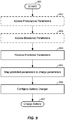
- Fig. 9 illustrates battery charging according to another aspect.
- Fig. 9 shows a more generic version of the example process shown in Fig. 8 .
- Battery charging may start at 901, when a user may plug an electronic device into a power source, such as a USB port, AC adapter, or other form of external power.
- prescriptive parameters are optionally accessed by a charging application.
- measured parameters are optionally accessed by the charging application.
- predicted parameters are received from a predictive engine, for example.
- the predicted parameters are mapped to charging parameters (e.g., charge current and/or float voltage). In some example aspects, the predicted parameters are mapped to charging parameters based on the prescribed and measured parameters, for example.
- the battery charger is configured with the charging parameters.
- battery charging is performed.
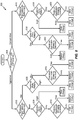
- Fig. 10 illustrates a block diagram of an exemplary battery charger system according to another aspect.
- system 1000 can reside at least partially within an electronic device (e.g., electronic device 100). It is to be appreciated that system 1000 is represented as including functional blocks, which can be functional blocks that represent functions implemented by a processor, software, battery charging circuits, and/or combination thereof. System 1000 includes a logical grouping 1050 of electrical components that can act in conjunction.
- logical grouping 1050 can include an electrical component that may provide means for receiving charge context information 1001. Further, logical grouping 1050 can include an electrical component that may provide means for generating a model establishing relations between data elements and charge duration 1002. Further, logical grouping 1050 can include an electrical component that may provide means for activating a battery charger 1003. Further, logical grouping 1050 can include an electrical component that may provide means for querying a predictive engine for duration 1004. Further, logical grouping 1050 can include an electrical component that may provide means for accessing current context information and comparing the current context information to a persisted model 1005. Further, logical grouping 1050 can include an electrical component that may provide means for outputting a predicted charge duration 1006.
- logical grouping 1050 can include an electrical component that may provide means for mapping charge duration to charging parameters 1007. Further, logical grouping 1050 can include an electrical component that may provide means for initiating a battery charge using custom charging parameters. Further, logical grouping 1050 can include an electrical component that may provide means for storing current context and update models 1009.
- system 1000 can include a memory 1051 that retains instructions for executing functions associated with the electrical components 1001, 1002, 1003, 1004, 1005, 1006, and 1007, and stores data used or obtained by the electrical components 1001, 1002, 1003, 1004, 1005, 1006, and 1007, etc. While shown as being external to memory 1051, it is to be understood that one or more of the electrical components 1001, 1002, 1003, 1004, 1005, 1006, and 1007 may exist within memory 1051.
- electrical components 1001, 1002, 1003, 1004, 1005, 1006, and 1007 can include at least one processor, or each electrical component 1001, 1002, 1003, 1004, 1005, 1006, and 1007 can be a corresponding module of at least one processor.
- electrical components 1001, 1002, 1003, 1004, 1005, 1006, and 1007 may be a computer program product including computer readable medium (e.g., non-transitory), where each electrical component 1001, 1002, 1003, 1004, 1005, 1006, and 1007 may be corresponding code.
Landscapes
- Engineering & Computer Science (AREA)
- Power Engineering (AREA)
- Microelectronics & Electronic Packaging (AREA)
- Manufacturing & Machinery (AREA)
- Chemical & Material Sciences (AREA)
- Chemical Kinetics & Catalysis (AREA)
- Electrochemistry (AREA)
- General Chemical & Material Sciences (AREA)
- Charge And Discharge Circuits For Batteries Or The Like (AREA)
- Secondary Cells (AREA)
- Telephone Function (AREA)
Claims (15)
- Un procédé comprenant :l'accès, par un dispositif électronique, à des informations de contexte décrivant un ou plusieurs modèles d'utilisation du dispositif électronique, etla prédiction, par le dispositif électronique, d'une durée de charge en fonction des informations de contexte, caractérisé parla détermination, par le dispositif électronique, de paramètres de charge en fonction de la durée de charge, les paramètres de charge étant utilisés de façon à charger une batterie du dispositif électronique, etla configuration d'un chargeur de batterie avec les paramètres de charge de façon à charger la batterie.
- Le procédé selon la Revendication 1, ladite prédiction comprenant la génération (502) d'un modèle établissant des relations entre des éléments de données des informations de contexte et la durée de charge.
- Le procédé selon la Revendication 2, ladite prédiction comprenant en outre :la conservation en mémoire des informations de contexte sous la forme de données d'historique de charge (412), etla comparaison des données d'historique de charge (412) à des informations de contexte actuelles de façon à prédire ladite durée de charge.
- Le procédé selon la Revendication 2, le modèle étant généré dynamiquement.
- Le procédé selon la Revendication 2, le modèle classant des informations de contexte passées et des éléments de contexte actuels en un nombre discret de durées de charge.
- Le procédé selon la Revendication 1, les paramètres de charge comprenant un courant de charge et une tension d'entretien.
- Le procédé selon la Revendication 1, les informations de contexte comprenant des paramètres mesurés et des paramètres normatifs, le procédé comprenant en outre la réception (501) de la durée de charge, des paramètres mesurés et des paramètres normatifs dans une application de charge et la mise en correspondance (507) de la durée de charge avec les paramètres de charge en fonction des paramètres mesurés et des paramètres normatifs.
- Le procédé selon la Revendication 1, les informations de contexte comprenant un état de charge (401), un temps de charge (403), un emplacement (404), une source de charge (405) et un niveau de batterie (402).
- Un dispositif électronique comprenant :un chargeur de batterie (111),une batterie (110),au moins un processeur configuré de façon à :accéder à des informations de contexte décrivant un ou plusieurs modèles d'utilisation du dispositif électronique, etprédire une durée de charge en fonction des informations de contexte, caractérisé de façon àdéterminer des paramètres de charge en fonction de la durée de charge, les paramètres de charge étant utilisés de façon à charger la batterie du dispositif électronique, etconfigurer le chargeur de batterie avec les paramètres de charge de façon à charger la batterie, etau moins une mémoire (1051) couplée au au moins un processeur.
- Le dispositif électronique selon la Revendication 9, le au moins un processeur étant configuré de façon à prédire la durée de charge par la génération (502) d'un modèle destiné à l'établissement de relations entre des éléments de données des informations de contexte et la durée de charge.
- Le dispositif électronique selon la Revendication 10, le au moins un processeur étant configuré en outre de façon à prédire la durée de charge par :la conservation en mémoire des informations de contexte sous la forme de données d'historique de charge (412), etla comparaison des données d'historique de charge (412) à des informations de contexte actuelles de façon à prédire ladite durée de charge.
- Le dispositif électronique selon la Revendication 10, le modèle étant généré dynamiquement.
- Le dispositif électronique selon la Revendication 10, le modèle classant des informations de contexte passées et des éléments de contexte actuels en un nombre discret de durées de charge.
- Le dispositif électronique selon la Revendication 9, les paramètres de charge comprenant un courant de charge et une tension d'entretien.
- Un support lisible par ordinateur non transitoire possédant conservées en mémoire sur celui-ci une ou plusieurs instructions, qui, lorsqu'elles sont exécutées par un ou plusieurs processeurs, amènent les un ou plusieurs processeurs à :accéder à des informations de contexte décrivant un ou plusieurs modèles d'utilisation du dispositif électronique, etprédire une durée de charge en fonction des informations de contexte, caractérisé de façon àdéterminer des paramètres de charge en fonction de la durée de charge, les paramètres de charge étant utilisés de façon à charger la batterie du dispositif électronique, etconfigurer le chargeur de batterie avec les paramètres de charge de façon à charger la batterie.
Applications Claiming Priority (3)
| Application Number | Priority Date | Filing Date | Title |
|---|---|---|---|
| US201361899624P | 2013-11-04 | 2013-11-04 | |
| US14/276,856 US20150123595A1 (en) | 2013-11-04 | 2014-05-13 | Intelligent context based battery charging |
| PCT/EP2014/073740 WO2015063340A1 (fr) | 2013-11-04 | 2014-11-04 | Charge intelligente de batterie reposant sur un contexte |
Publications (2)
| Publication Number | Publication Date |
|---|---|
| EP3066743A1 EP3066743A1 (fr) | 2016-09-14 |
| EP3066743B1 true EP3066743B1 (fr) | 2017-12-20 |
Family
ID=52011152
Family Applications (1)
| Application Number | Title | Priority Date | Filing Date |
|---|---|---|---|
| EP14808516.0A Not-in-force EP3066743B1 (fr) | 2013-11-04 | 2014-11-04 | Charge intelligente de batterie reposant sur un contexte |
Country Status (7)
| Country | Link |
|---|---|
| US (1) | US20150123595A1 (fr) |
| EP (1) | EP3066743B1 (fr) |
| JP (1) | JP6486916B2 (fr) |
| KR (1) | KR20160078496A (fr) |
| CN (1) | CN105684260B (fr) |
| TW (1) | TWI660555B (fr) |
| WO (1) | WO2015063340A1 (fr) |
Cited By (2)
| Publication number | Priority date | Publication date | Assignee | Title |
|---|---|---|---|---|
| WO2020055328A1 (fr) * | 2018-09-14 | 2020-03-19 | Health Partners Pte Ltd | Système pour maximiser la vitesse de stockage d'énergie |
| US11165269B2 (en) | 2018-02-23 | 2021-11-02 | Asustek Computer Inc. | Electronic apparatus, charging method, and non-transitory computer readable recording medium |
Families Citing this family (51)
| Publication number | Priority date | Publication date | Assignee | Title |
|---|---|---|---|---|
| US9531202B2 (en) * | 2014-03-10 | 2016-12-27 | Dell Products, L.P. | Battery management system and method for charging lithium-ion battery cells in an information handling system |
| US20160111905A1 (en) * | 2014-10-17 | 2016-04-21 | Elwha Llc | Systems and methods for charging energy storage devices |
| US10158148B2 (en) | 2015-02-18 | 2018-12-18 | Microsoft Technology Licensing, Llc | Dynamically changing internal state of a battery |
| US20160275400A1 (en) * | 2015-03-19 | 2016-09-22 | Microsoft Technology Licensing, Llc | Device Charging Discovery Service |
| CN105098900B (zh) | 2015-08-05 | 2018-05-29 | 青岛海信移动通信技术股份有限公司 | 移动终端、可直充电源适配器及充电方法 |
| US10663529B1 (en) * | 2015-09-25 | 2020-05-26 | Amazon Technologies, Inc. | Automatic battery charging |
| KR102547376B1 (ko) * | 2016-03-03 | 2023-06-26 | 삼성전자주식회사 | 전자 장치, 충전 제어 방법 및 컴퓨터 판독가능 기록매체 |
| WO2017206107A1 (fr) | 2016-06-01 | 2017-12-07 | 华为技术有限公司 | Procédé de charge et terminal |
| KR20180022517A (ko) * | 2016-08-23 | 2018-03-06 | 삼성전자주식회사 | 전력 제공 장치 및 전력을 수신하는 전자 장치와 그 제어 방법 |
| WO2018038423A1 (fr) | 2016-08-23 | 2018-03-01 | 삼성전자 주식회사 | Appareil d'alimentation électrique, dispositif électronique recevant de l'énergie, et son procédé de commande |
| US11761765B2 (en) | 2016-09-09 | 2023-09-19 | Nextnav, Llc | Calibrating a pressure sensor |
| CN117782153A (zh) * | 2016-09-09 | 2024-03-29 | 内克斯特纳夫有限公司 | 用于校准不稳定传感器的系统和方法 |
| US11309717B2 (en) * | 2016-09-26 | 2022-04-19 | Samsung Electronics Co., Ltd. | Apparatus and method for battery management |
| CN107959314A (zh) * | 2016-10-17 | 2018-04-24 | 中兴通讯股份有限公司 | 一种慢充电方法及智能终端 |
| US10346812B2 (en) | 2017-01-07 | 2019-07-09 | International Business Machines Corporation | Charge management |
| US10606336B2 (en) * | 2017-06-16 | 2020-03-31 | Apple Inc. | Electronic device with improved power management |
| US10661659B2 (en) | 2017-06-21 | 2020-05-26 | Cyberswitchingpatents, LLC. | Integrated management of electric vehicle charging and non-electric vehicle fueling |
| US20180375344A1 (en) * | 2017-06-23 | 2018-12-27 | Intel Corporation | Situational battery charging |
| US10705584B2 (en) * | 2017-07-11 | 2020-07-07 | International Business Machines Corporation | Power socket management system |
| KR102284338B1 (ko) | 2017-07-26 | 2021-08-03 | 에스케이이노베이션 주식회사 | 배터리 충방전 예상 장치 및 방법 |
| CN109449692B (zh) * | 2017-09-01 | 2020-06-12 | 硕天科技股份有限公司 | 配接器与配接器模块 |
| US11152809B2 (en) | 2017-10-30 | 2021-10-19 | Hewlett-Packard Development Company, L.P. | User behavior driven charge levels |
| CN107769324B (zh) * | 2017-11-14 | 2021-01-12 | 维沃移动通信有限公司 | 一种充电方法、充电器、移动终端及服务器 |
| KR102530221B1 (ko) * | 2017-11-28 | 2023-05-09 | 삼성전자주식회사 | 배터리 관리 방법 및 장치 |
| US11451067B2 (en) * | 2017-12-19 | 2022-09-20 | Intel Corporation | Method, apparatus and system to enhance a device policy manager to manage devices based on battery condition |
| US11038364B2 (en) | 2018-01-10 | 2021-06-15 | Microsoft Technology Licensing, Llc | Parallel charging and discharging of batteries with disparate characteristics |
| KR102440486B1 (ko) * | 2018-02-06 | 2022-09-06 | 주식회사 엘지에너지솔루션 | 빅데이터 기반 이차 전지 활성화 시스템 및 이를 이용한 이차 전지의 활성화 방법 |
| TWI669603B (zh) * | 2018-02-23 | 2019-08-21 | 宏碁股份有限公司 | 適應性調整充電目標的方法及智慧型裝置 |
| JP7401455B2 (ja) * | 2018-04-13 | 2023-12-19 | ローベルト ボツシユ ゲゼルシヤフト ミツト ベシユレンクテル ハフツング | 最適化システム及び最適化方法 |
| US11152810B2 (en) * | 2018-05-21 | 2021-10-19 | Sling Media Pvt. Ltd. | Rule based smart charging |
| US20220115893A1 (en) * | 2019-01-21 | 2022-04-14 | Qualcomm Inc | Smart battery fast charging |
| WO2020162646A1 (fr) * | 2019-02-07 | 2020-08-13 | 엘지전자 주식회사 | Terminal mobile et son procédé de commande |
| US11165270B2 (en) | 2019-03-21 | 2021-11-02 | Microsoft Technology Licensing, Llc | Predictive management of battery operation |
| CN111864280B (zh) * | 2019-04-30 | 2022-02-01 | 凹凸电子(武汉)有限公司 | 控制器及电池管理方法 |
| US11101680B2 (en) | 2019-06-28 | 2021-08-24 | Microsoft Technology Licensing, Llc | Parallel battery charge management |
| US11086380B2 (en) * | 2019-09-20 | 2021-08-10 | Dell Products, L.P. | Management of battery runtime based upon power source activity |
| CN112558740B (zh) * | 2019-09-26 | 2024-02-13 | 戴尔产品有限公司 | 组件节流电力备用设备充电系统 |
| CN110829528B (zh) * | 2019-11-13 | 2024-04-05 | Oppo广东移动通信有限公司 | 充电方法、设备及可读存储介质 |
| US11355944B2 (en) * | 2019-11-15 | 2022-06-07 | Google Llc | Predictive charging to reduce battery capacity degradation |
| CN110867922B (zh) * | 2019-11-27 | 2021-12-10 | 威海安屯尼智能电子科技有限公司 | 一种浮充阶段拉高电压的脉冲充电方法及电源充电器 |
| CN113497468A (zh) * | 2020-03-20 | 2021-10-12 | 华为技术有限公司 | 一种充电管控方法及电子设备 |
| US20210336464A1 (en) * | 2020-04-28 | 2021-10-28 | Intel Corporation | Inference based fast charging |
| CN111564877A (zh) * | 2020-04-30 | 2020-08-21 | 华为技术有限公司 | 用于充电管控的方法和装置 |
| US11901749B2 (en) | 2020-09-09 | 2024-02-13 | Microsoft Technology Licensing, Llc | Balanced discharge in multi-battery system |
| CN112477692B (zh) * | 2020-11-25 | 2022-03-01 | 中国第一汽车股份有限公司 | 一种电动汽车动力电池的充电控制方法及装置 |
| US11605966B2 (en) * | 2020-12-02 | 2023-03-14 | Dish Network L.L.C. | Anticipatory event based battery charging |
| US11623540B2 (en) | 2021-01-13 | 2023-04-11 | Toyota Motor North America, Inc. | Transport recharge level determination |
| US11987144B2 (en) | 2021-01-13 | 2024-05-21 | Toyota Motor North America, Inc. | Transport energy transfer using real-time cost information |
| US20220407329A1 (en) * | 2021-06-16 | 2022-12-22 | Hewlett-Packard Development Company, L.P. | Battery charge regulation |
| TWI814114B (zh) * | 2021-10-25 | 2023-09-01 | 楊盛安 | 充電式物件、目標充電量預設及達標通知系統及方法、使用此方法的記錄媒體及程式產品 |
| US20230147536A1 (en) * | 2021-11-10 | 2023-05-11 | Powermat Technologies Ltd. | Green battery charger and framework |
Family Cites Families (20)
| Publication number | Priority date | Publication date | Assignee | Title |
|---|---|---|---|---|
| US6885195B2 (en) * | 1996-07-29 | 2005-04-26 | Midtronics, Inc. | Method and apparatus for auditing a battery test |
| US6816466B1 (en) * | 2000-06-02 | 2004-11-09 | Astec International Limited | Automatic module configuration in a telecommunications power system |
| JP4039355B2 (ja) * | 2003-10-29 | 2008-01-30 | トヨタ自動車株式会社 | 二次電池の制御装置および制御方法 |
| WO2007016191A2 (fr) * | 2005-07-27 | 2007-02-08 | Flaugher David J | Chargeurs de batterie et methodes pour prolonger une duree de vie de batterie |
| US7696719B2 (en) * | 2006-03-07 | 2010-04-13 | Fujitsu Ten Limited | Power control apparatus, power control method |
| US20090243549A1 (en) * | 2008-03-31 | 2009-10-01 | Naoki Matsumura | Intelligent battery charging rate management |
| US8896272B2 (en) * | 2008-05-30 | 2014-11-25 | Qualcomm, Incorporated | Systems and methods of battery charging with dynamic float voltage |
| EP2190097B1 (fr) * | 2008-11-25 | 2012-05-16 | ABB Research Ltd. | Procédé pour commander un système de stockage d'énergie |
| JP2011018959A (ja) * | 2009-07-07 | 2011-01-27 | Murata Mfg Co Ltd | 圧電振動子 |
| US8390249B2 (en) * | 2009-11-30 | 2013-03-05 | Broadcom Corporation | Battery with integrated wireless power receiver and/or RFID |
| DE102010020993A1 (de) * | 2010-05-19 | 2011-11-24 | Li-Tec Battery Gmbh | Verfahren zum Steuern der maximalen Laderate einer elektrochemischen Energiespeichereinrichtung |
| US20130234649A1 (en) * | 2010-10-18 | 2013-09-12 | Belkin International, Inc. | Battery management system and method therefor |
| KR101440530B1 (ko) * | 2011-01-05 | 2014-09-18 | 주식회사 엘지화학 | 배터리 가용시간 추정 장치 및 방법 |
| JP2012151946A (ja) * | 2011-01-17 | 2012-08-09 | Alpine Electronics Inc | 充電装置 |
| WO2012166095A1 (fr) * | 2011-05-27 | 2012-12-06 | Empire Technology Development Llc | Gestion de batterie de dispositif |
| US9152202B2 (en) * | 2011-06-16 | 2015-10-06 | Microsoft Technology Licensing, Llc | Mobile device operations with battery optimization |
| US20130035812A1 (en) * | 2011-08-04 | 2013-02-07 | Gm Global Technology Operations Llp | Battery charging system and method |
| US20130246595A1 (en) | 2011-10-18 | 2013-09-19 | Hugh O'Donoghue | Method and apparatus for using an organizational structure for generating, using, or updating an enriched user profile |
| US9059590B2 (en) * | 2013-02-26 | 2015-06-16 | Bby Solutions, Inc. | Universal battery charger system and method |
| US9270140B2 (en) * | 2013-05-14 | 2016-02-23 | Stored Energy Systems | Dynamic boost battery chargers |
-
2014
- 2014-05-13 US US14/276,856 patent/US20150123595A1/en not_active Abandoned
- 2014-11-04 EP EP14808516.0A patent/EP3066743B1/fr not_active Not-in-force
- 2014-11-04 CN CN201480059261.9A patent/CN105684260B/zh not_active Expired - Fee Related
- 2014-11-04 TW TW103138224A patent/TWI660555B/zh not_active IP Right Cessation
- 2014-11-04 KR KR1020167014698A patent/KR20160078496A/ko not_active Application Discontinuation
- 2014-11-04 JP JP2016526805A patent/JP6486916B2/ja not_active Expired - Fee Related
- 2014-11-04 WO PCT/EP2014/073740 patent/WO2015063340A1/fr active Application Filing
Cited By (2)
| Publication number | Priority date | Publication date | Assignee | Title |
|---|---|---|---|---|
| US11165269B2 (en) | 2018-02-23 | 2021-11-02 | Asustek Computer Inc. | Electronic apparatus, charging method, and non-transitory computer readable recording medium |
| WO2020055328A1 (fr) * | 2018-09-14 | 2020-03-19 | Health Partners Pte Ltd | Système pour maximiser la vitesse de stockage d'énergie |
Also Published As
| Publication number | Publication date |
|---|---|
| KR20160078496A (ko) | 2016-07-04 |
| CN105684260B (zh) | 2019-12-10 |
| EP3066743A1 (fr) | 2016-09-14 |
| US20150123595A1 (en) | 2015-05-07 |
| WO2015063340A1 (fr) | 2015-05-07 |
| JP2016537877A (ja) | 2016-12-01 |
| CN105684260A (zh) | 2016-06-15 |
| TWI660555B (zh) | 2019-05-21 |
| TW201539932A (zh) | 2015-10-16 |
| JP6486916B2 (ja) | 2019-03-20 |
Similar Documents
| Publication | Publication Date | Title |
|---|---|---|
| EP3066743B1 (fr) | Charge intelligente de batterie reposant sur un contexte | |
| US7570015B2 (en) | Conditional battery charging system | |
| US9948122B2 (en) | Smart battery charging to improve the lifespan of batteries | |
| US9285851B2 (en) | Optimizing battery use for known future load | |
| US11955827B2 (en) | Rule based smart charging | |
| US20080218125A1 (en) | Battery Charging System | |
| US9411398B2 (en) | Electronic device and method to extend battery life | |
| US8310205B1 (en) | Managed battery charging | |
| US20150084778A1 (en) | System and method to estimate duration of battery (dis)charging of an electronic device and provide smart charging alerts based on device usage pattern | |
| WO2013112599A1 (fr) | Gestion d'énergie destinée à des dispositifs électroniques | |
| US20150257103A1 (en) | Method and device with an augmented rules engine | |
| US9619010B1 (en) | Selective powering off of hardware components for battery management in mobile devices | |
| CN105659188A (zh) | 上下文功率管理 | |
| US9252618B2 (en) | Terminals, terminal systems and charging/discharging methods thereof | |
| CN106303096B (zh) | 电子设备及其调整电源管理策略的方法 | |
| EP2889719B1 (fr) | Procédé et appareil pour gérer l'utilisation de puissance dans un processeur | |
| WO2017215266A1 (fr) | Procédé et dispositif de charge pour terminal | |
| CN110148992B (zh) | 一种充电控制方法、终端设备及存储介质 | |
| CN103516873A (zh) | 一种信息处理方法及一种电子设备 | |
| US20220260639A1 (en) | Systems and methods for managing use of portable ihs batteries | |
| CN108156649A (zh) | 一种具有共享电源功能的智能手机 | |
| CN102915106A (zh) | 便携式装置的电源管理方法 | |
| Parmar et al. | Android Hardware Management |
Legal Events
| Date | Code | Title | Description |
|---|---|---|---|
| PUAI | Public reference made under article 153(3) epc to a published international application that has entered the european phase |
Free format text: ORIGINAL CODE: 0009012 |
|
| 17P | Request for examination filed |
Effective date: 20160407 |
|
| AK | Designated contracting states |
Kind code of ref document: A1 Designated state(s): AL AT BE BG CH CY CZ DE DK EE ES FI FR GB GR HR HU IE IS IT LI LT LU LV MC MK MT NL NO PL PT RO RS SE SI SK SM TR |
|
| AX | Request for extension of the european patent |
Extension state: BA ME |
|
| DAX | Request for extension of the european patent (deleted) | ||
| REG | Reference to a national code |
Ref country code: DE Ref legal event code: R079 Ref document number: 602014018903 Country of ref document: DE Free format text: PREVIOUS MAIN CLASS: H02J0007040000 Ipc: H02J0007000000 |
|
| GRAP | Despatch of communication of intention to grant a patent |
Free format text: ORIGINAL CODE: EPIDOSNIGR1 |
|
| STAA | Information on the status of an ep patent application or granted ep patent |
Free format text: STATUS: GRANT OF PATENT IS INTENDED |
|
| RIC1 | Information provided on ipc code assigned before grant |
Ipc: H02J 7/00 20060101AFI20170609BHEP Ipc: H02J 7/04 20060101ALI20170609BHEP |
|
| INTG | Intention to grant announced |
Effective date: 20170630 |
|
| GRAS | Grant fee paid |
Free format text: ORIGINAL CODE: EPIDOSNIGR3 |
|
| GRAA | (expected) grant |
Free format text: ORIGINAL CODE: 0009210 |
|
| STAA | Information on the status of an ep patent application or granted ep patent |
Free format text: STATUS: THE PATENT HAS BEEN GRANTED |
|
| AK | Designated contracting states |
Kind code of ref document: B1 Designated state(s): AL AT BE BG CH CY CZ DE DK EE ES FI FR GB GR HR HU IE IS IT LI LT LU LV MC MK MT NL NO PL PT RO RS SE SI SK SM TR |
|
| REG | Reference to a national code |
Ref country code: GB Ref legal event code: FG4D |
|
| REG | Reference to a national code |
Ref country code: CH Ref legal event code: EP |
|
| REG | Reference to a national code |
Ref country code: IE Ref legal event code: FG4D |
|
| REG | Reference to a national code |
Ref country code: AT Ref legal event code: REF Ref document number: 957202 Country of ref document: AT Kind code of ref document: T Effective date: 20180115 |
|
| REG | Reference to a national code |
Ref country code: DE Ref legal event code: R096 Ref document number: 602014018903 Country of ref document: DE |
|
| REG | Reference to a national code |
Ref country code: NL Ref legal event code: MP Effective date: 20171220 |
|
| PG25 | Lapsed in a contracting state [announced via postgrant information from national office to epo] |
Ref country code: SE Free format text: LAPSE BECAUSE OF FAILURE TO SUBMIT A TRANSLATION OF THE DESCRIPTION OR TO PAY THE FEE WITHIN THE PRESCRIBED TIME-LIMIT Effective date: 20171220 Ref country code: LT Free format text: LAPSE BECAUSE OF FAILURE TO SUBMIT A TRANSLATION OF THE DESCRIPTION OR TO PAY THE FEE WITHIN THE PRESCRIBED TIME-LIMIT Effective date: 20171220 Ref country code: NO Free format text: LAPSE BECAUSE OF FAILURE TO SUBMIT A TRANSLATION OF THE DESCRIPTION OR TO PAY THE FEE WITHIN THE PRESCRIBED TIME-LIMIT Effective date: 20180320 Ref country code: FI Free format text: LAPSE BECAUSE OF FAILURE TO SUBMIT A TRANSLATION OF THE DESCRIPTION OR TO PAY THE FEE WITHIN THE PRESCRIBED TIME-LIMIT Effective date: 20171220 |
|
| REG | Reference to a national code |
Ref country code: LT Ref legal event code: MG4D |
|
| REG | Reference to a national code |
Ref country code: AT Ref legal event code: MK05 Ref document number: 957202 Country of ref document: AT Kind code of ref document: T Effective date: 20171220 |
|
| PG25 | Lapsed in a contracting state [announced via postgrant information from national office to epo] |
Ref country code: RS Free format text: LAPSE BECAUSE OF FAILURE TO SUBMIT A TRANSLATION OF THE DESCRIPTION OR TO PAY THE FEE WITHIN THE PRESCRIBED TIME-LIMIT Effective date: 20171220 Ref country code: LV Free format text: LAPSE BECAUSE OF FAILURE TO SUBMIT A TRANSLATION OF THE DESCRIPTION OR TO PAY THE FEE WITHIN THE PRESCRIBED TIME-LIMIT Effective date: 20171220 Ref country code: HR Free format text: LAPSE BECAUSE OF FAILURE TO SUBMIT A TRANSLATION OF THE DESCRIPTION OR TO PAY THE FEE WITHIN THE PRESCRIBED TIME-LIMIT Effective date: 20171220 Ref country code: GR Free format text: LAPSE BECAUSE OF FAILURE TO SUBMIT A TRANSLATION OF THE DESCRIPTION OR TO PAY THE FEE WITHIN THE PRESCRIBED TIME-LIMIT Effective date: 20180321 Ref country code: BG Free format text: LAPSE BECAUSE OF FAILURE TO SUBMIT A TRANSLATION OF THE DESCRIPTION OR TO PAY THE FEE WITHIN THE PRESCRIBED TIME-LIMIT Effective date: 20180320 |
|
| PG25 | Lapsed in a contracting state [announced via postgrant information from national office to epo] |
Ref country code: NL Free format text: LAPSE BECAUSE OF FAILURE TO SUBMIT A TRANSLATION OF THE DESCRIPTION OR TO PAY THE FEE WITHIN THE PRESCRIBED TIME-LIMIT Effective date: 20171220 |
|
| PG25 | Lapsed in a contracting state [announced via postgrant information from national office to epo] |
Ref country code: ES Free format text: LAPSE BECAUSE OF FAILURE TO SUBMIT A TRANSLATION OF THE DESCRIPTION OR TO PAY THE FEE WITHIN THE PRESCRIBED TIME-LIMIT Effective date: 20171220 Ref country code: CZ Free format text: LAPSE BECAUSE OF FAILURE TO SUBMIT A TRANSLATION OF THE DESCRIPTION OR TO PAY THE FEE WITHIN THE PRESCRIBED TIME-LIMIT Effective date: 20171220 Ref country code: CY Free format text: LAPSE BECAUSE OF FAILURE TO SUBMIT A TRANSLATION OF THE DESCRIPTION OR TO PAY THE FEE WITHIN THE PRESCRIBED TIME-LIMIT Effective date: 20171220 Ref country code: EE Free format text: LAPSE BECAUSE OF FAILURE TO SUBMIT A TRANSLATION OF THE DESCRIPTION OR TO PAY THE FEE WITHIN THE PRESCRIBED TIME-LIMIT Effective date: 20171220 Ref country code: SK Free format text: LAPSE BECAUSE OF FAILURE TO SUBMIT A TRANSLATION OF THE DESCRIPTION OR TO PAY THE FEE WITHIN THE PRESCRIBED TIME-LIMIT Effective date: 20171220 |
|
| PG25 | Lapsed in a contracting state [announced via postgrant information from national office to epo] |
Ref country code: IT Free format text: LAPSE BECAUSE OF FAILURE TO SUBMIT A TRANSLATION OF THE DESCRIPTION OR TO PAY THE FEE WITHIN THE PRESCRIBED TIME-LIMIT Effective date: 20171220 Ref country code: SM Free format text: LAPSE BECAUSE OF FAILURE TO SUBMIT A TRANSLATION OF THE DESCRIPTION OR TO PAY THE FEE WITHIN THE PRESCRIBED TIME-LIMIT Effective date: 20171220 Ref country code: IS Free format text: LAPSE BECAUSE OF FAILURE TO SUBMIT A TRANSLATION OF THE DESCRIPTION OR TO PAY THE FEE WITHIN THE PRESCRIBED TIME-LIMIT Effective date: 20180420 Ref country code: RO Free format text: LAPSE BECAUSE OF FAILURE TO SUBMIT A TRANSLATION OF THE DESCRIPTION OR TO PAY THE FEE WITHIN THE PRESCRIBED TIME-LIMIT Effective date: 20171220 Ref country code: AT Free format text: LAPSE BECAUSE OF FAILURE TO SUBMIT A TRANSLATION OF THE DESCRIPTION OR TO PAY THE FEE WITHIN THE PRESCRIBED TIME-LIMIT Effective date: 20171220 Ref country code: PL Free format text: LAPSE BECAUSE OF FAILURE TO SUBMIT A TRANSLATION OF THE DESCRIPTION OR TO PAY THE FEE WITHIN THE PRESCRIBED TIME-LIMIT Effective date: 20171220 |
|
| REG | Reference to a national code |
Ref country code: DE Ref legal event code: R097 Ref document number: 602014018903 Country of ref document: DE |
|
| REG | Reference to a national code |
Ref country code: FR Ref legal event code: PLFP Year of fee payment: 5 |
|
| PLBE | No opposition filed within time limit |
Free format text: ORIGINAL CODE: 0009261 |
|
| STAA | Information on the status of an ep patent application or granted ep patent |
Free format text: STATUS: NO OPPOSITION FILED WITHIN TIME LIMIT |
|
| PG25 | Lapsed in a contracting state [announced via postgrant information from national office to epo] |
Ref country code: DK Free format text: LAPSE BECAUSE OF FAILURE TO SUBMIT A TRANSLATION OF THE DESCRIPTION OR TO PAY THE FEE WITHIN THE PRESCRIBED TIME-LIMIT Effective date: 20171220 |
|
| 26N | No opposition filed |
Effective date: 20180921 |
|
| PG25 | Lapsed in a contracting state [announced via postgrant information from national office to epo] |
Ref country code: SI Free format text: LAPSE BECAUSE OF FAILURE TO SUBMIT A TRANSLATION OF THE DESCRIPTION OR TO PAY THE FEE WITHIN THE PRESCRIBED TIME-LIMIT Effective date: 20171220 |
|
| REG | Reference to a national code |
Ref country code: CH Ref legal event code: PL |
|
| PG25 | Lapsed in a contracting state [announced via postgrant information from national office to epo] |
Ref country code: MC Free format text: LAPSE BECAUSE OF FAILURE TO SUBMIT A TRANSLATION OF THE DESCRIPTION OR TO PAY THE FEE WITHIN THE PRESCRIBED TIME-LIMIT Effective date: 20171220 Ref country code: LU Free format text: LAPSE BECAUSE OF NON-PAYMENT OF DUE FEES Effective date: 20181104 |
|
| REG | Reference to a national code |
Ref country code: BE Ref legal event code: MM Effective date: 20181130 |
|
| REG | Reference to a national code |
Ref country code: IE Ref legal event code: MM4A |
|
| PG25 | Lapsed in a contracting state [announced via postgrant information from national office to epo] |
Ref country code: LI Free format text: LAPSE BECAUSE OF NON-PAYMENT OF DUE FEES Effective date: 20181130 Ref country code: CH Free format text: LAPSE BECAUSE OF NON-PAYMENT OF DUE FEES Effective date: 20181130 |
|
| PG25 | Lapsed in a contracting state [announced via postgrant information from national office to epo] |
Ref country code: IE Free format text: LAPSE BECAUSE OF NON-PAYMENT OF DUE FEES Effective date: 20181104 |
|
| PG25 | Lapsed in a contracting state [announced via postgrant information from national office to epo] |
Ref country code: BE Free format text: LAPSE BECAUSE OF NON-PAYMENT OF DUE FEES Effective date: 20181130 |
|
| PG25 | Lapsed in a contracting state [announced via postgrant information from national office to epo] |
Ref country code: MT Free format text: LAPSE BECAUSE OF NON-PAYMENT OF DUE FEES Effective date: 20181104 |
|
| PGFP | Annual fee paid to national office [announced via postgrant information from national office to epo] |
Ref country code: DE Payment date: 20191017 Year of fee payment: 6 |
|
| PGFP | Annual fee paid to national office [announced via postgrant information from national office to epo] |
Ref country code: FR Payment date: 20191029 Year of fee payment: 6 |
|
| PG25 | Lapsed in a contracting state [announced via postgrant information from national office to epo] |
Ref country code: TR Free format text: LAPSE BECAUSE OF FAILURE TO SUBMIT A TRANSLATION OF THE DESCRIPTION OR TO PAY THE FEE WITHIN THE PRESCRIBED TIME-LIMIT Effective date: 20171220 |
|
| PGFP | Annual fee paid to national office [announced via postgrant information from national office to epo] |
Ref country code: GB Payment date: 20191029 Year of fee payment: 6 |
|
| PG25 | Lapsed in a contracting state [announced via postgrant information from national office to epo] |
Ref country code: PT Free format text: LAPSE BECAUSE OF FAILURE TO SUBMIT A TRANSLATION OF THE DESCRIPTION OR TO PAY THE FEE WITHIN THE PRESCRIBED TIME-LIMIT Effective date: 20171220 |
|
| PG25 | Lapsed in a contracting state [announced via postgrant information from national office to epo] |
Ref country code: HU Free format text: LAPSE BECAUSE OF FAILURE TO SUBMIT A TRANSLATION OF THE DESCRIPTION OR TO PAY THE FEE WITHIN THE PRESCRIBED TIME-LIMIT; INVALID AB INITIO Effective date: 20141104 Ref country code: MK Free format text: LAPSE BECAUSE OF NON-PAYMENT OF DUE FEES Effective date: 20171220 |
|
| PG25 | Lapsed in a contracting state [announced via postgrant information from national office to epo] |
Ref country code: AL Free format text: LAPSE BECAUSE OF FAILURE TO SUBMIT A TRANSLATION OF THE DESCRIPTION OR TO PAY THE FEE WITHIN THE PRESCRIBED TIME-LIMIT Effective date: 20171220 |
|
| REG | Reference to a national code |
Ref country code: DE Ref legal event code: R119 Ref document number: 602014018903 Country of ref document: DE |
|
| GBPC | Gb: european patent ceased through non-payment of renewal fee |
Effective date: 20201104 |
|
| PG25 | Lapsed in a contracting state [announced via postgrant information from national office to epo] |
Ref country code: FR Free format text: LAPSE BECAUSE OF NON-PAYMENT OF DUE FEES Effective date: 20201130 |
|
| PG25 | Lapsed in a contracting state [announced via postgrant information from national office to epo] |
Ref country code: DE Free format text: LAPSE BECAUSE OF NON-PAYMENT OF DUE FEES Effective date: 20210601 Ref country code: GB Free format text: LAPSE BECAUSE OF NON-PAYMENT OF DUE FEES Effective date: 20201104 |