EP3066456B1 - Inspection apparatus - Google Patents
Inspection apparatus Download PDFInfo
- Publication number
- EP3066456B1 EP3066456B1 EP14792832.9A EP14792832A EP3066456B1 EP 3066456 B1 EP3066456 B1 EP 3066456B1 EP 14792832 A EP14792832 A EP 14792832A EP 3066456 B1 EP3066456 B1 EP 3066456B1
- Authority
- EP
- European Patent Office
- Prior art keywords
- stream
- matter
- detector
- light source
- light beam
- Prior art date
- Legal status (The legal status is an assumption and is not a legal conclusion. Google has not performed a legal analysis and makes no representation as to the accuracy of the status listed.)
- Active
Links
Images
Classifications
-
- G—PHYSICS
- G01—MEASURING; TESTING
- G01N—INVESTIGATING OR ANALYSING MATERIALS BY DETERMINING THEIR CHEMICAL OR PHYSICAL PROPERTIES
- G01N1/00—Sampling; Preparing specimens for investigation
- G01N1/02—Devices for withdrawing samples
- G01N1/22—Devices for withdrawing samples in the gaseous state
- G01N1/2247—Sampling from a flowing stream of gas
-
- G—PHYSICS
- G01—MEASURING; TESTING
- G01N—INVESTIGATING OR ANALYSING MATERIALS BY DETERMINING THEIR CHEMICAL OR PHYSICAL PROPERTIES
- G01N21/00—Investigating or analysing materials by the use of optical means, i.e. using sub-millimetre waves, infrared, visible or ultraviolet light
- G01N21/84—Systems specially adapted for particular applications
- G01N21/85—Investigating moving fluids or granular solids
-
- B—PERFORMING OPERATIONS; TRANSPORTING
- B07—SEPARATING SOLIDS FROM SOLIDS; SORTING
- B07C—POSTAL SORTING; SORTING INDIVIDUAL ARTICLES, OR BULK MATERIAL FIT TO BE SORTED PIECE-MEAL, e.g. BY PICKING
- B07C5/00—Sorting according to a characteristic or feature of the articles or material being sorted, e.g. by control effected by devices which detect or measure such characteristic or feature; Sorting by manually actuated devices, e.g. switches
- B07C5/34—Sorting according to other particular properties
- B07C5/342—Sorting according to other particular properties according to optical properties, e.g. colour
-
- G—PHYSICS
- G01—MEASURING; TESTING
- G01N—INVESTIGATING OR ANALYSING MATERIALS BY DETERMINING THEIR CHEMICAL OR PHYSICAL PROPERTIES
- G01N2201/00—Features of devices classified in G01N21/00
- G01N2201/06—Illumination; Optics
- G01N2201/061—Sources
- G01N2201/06113—Coherent sources; lasers
-
- G—PHYSICS
- G01—MEASURING; TESTING
- G01N—INVESTIGATING OR ANALYSING MATERIALS BY DETERMINING THEIR CHEMICAL OR PHYSICAL PROPERTIES
- G01N2201/00—Features of devices classified in G01N21/00
- G01N2201/06—Illumination; Optics
- G01N2201/061—Sources
- G01N2201/06193—Secondary in situ sources, e.g. fluorescent particles
-
- G—PHYSICS
- G01—MEASURING; TESTING
- G01N—INVESTIGATING OR ANALYSING MATERIALS BY DETERMINING THEIR CHEMICAL OR PHYSICAL PROPERTIES
- G01N2201/00—Features of devices classified in G01N21/00
- G01N2201/06—Illumination; Optics
- G01N2201/062—LED's
-
- G—PHYSICS
- G01—MEASURING; TESTING
- G01N—INVESTIGATING OR ANALYSING MATERIALS BY DETERMINING THEIR CHEMICAL OR PHYSICAL PROPERTIES
- G01N2201/00—Features of devices classified in G01N21/00
- G01N2201/06—Illumination; Optics
- G01N2201/063—Illuminating optical parts
- G01N2201/0636—Reflectors
-
- G—PHYSICS
- G01—MEASURING; TESTING
- G01N—INVESTIGATING OR ANALYSING MATERIALS BY DETERMINING THEIR CHEMICAL OR PHYSICAL PROPERTIES
- G01N2201/00—Features of devices classified in G01N21/00
- G01N2201/06—Illumination; Optics
- G01N2201/068—Optics, miscellaneous
Definitions
- the present invention relates to an apparatus for inspecting a stream of matter, as well as a system comprising such an apparatus.
- EP 1 185 854 discloses a detection station including a vertically downwardly directed video camera and a detection unit,which station has a stream of waste matter advanced therethrough on a substantially horizontal conveyor belt to a transverse array of air jet nozzles.
- the rectangular picture area of the camera spans the whole width of the belt and thus of the stream of waste.
- the data from the camera is used to identify the positions of individual objects in the waste stream (in the sense of approximately the region that the object occupies in the stream of waste).
- the unit scans the stream of waste along a rectilinear path P also extending the whole width of the belt and thus of the waste stream, the path P being perpendicular to the longitudinal direction D of the belt, i.e. to the feed direction of the waste stream.
- the unit detects the composition of at least some of the objects in the waste stream.
- the data from the camera and the unit are used to control a controller for solenoid valves which control the supply of compressed air to the respective nozzles.
- the composition and/or colour of each object is/are detected by the unit, whilst the video camera is used to monitor the scanned region and its data output employed automatically to detect the positions of the objects and to correct the data relating to those objects as received from detectors in the unit.
- US 6 473 168 B1 discloses a method and a device for detecting irregularities in a product, in which at least one light band is directed towards this product.
- the product moves in a particular direction through a detection zone, so that said light band is scattered and/or reflected by said product, and the scattered light is detected by at least one detector in order to detect irregularities in the product.
- the light stream scattered by a part of the product and captured by said detector is adjusted so that it is independent of its position in said detection zone.
- CA 2 697 636 A1 relates to a system comprising a broadband optical light source and a sorting device, more specifically to laser sorting devices. It discloses a system comprising a sorting device with a light-source offering all wavelengths for the sorting process, using an all fiber supercontinuum light source.
- an apparatus for inspecting a stream of matter which comprises a first and a second light source, a first and a second detector as well as a first scanning element and a first beam splitter.
- Said first light source is adapted to emit a first light beam comprising wavelengths within a first wavelength range ( ⁇ 1a - ⁇ 1b ), for illuminating said stream of matter from side to side; and the first detector is arranged to receive said first light beam after it has been reflected against said stream of matter at a first detection area.
- the second light source is adapted to emit a second light beam comprising wavelengths within a second wavelength range ( ⁇ 2a - ⁇ 2b ), for illuminating said stream of matter at an illuminated area, wherein any wavelength ( ⁇ 1 ) in said first wavelength range is different from any wavelength ( ⁇ 2 ) in said second wavelength range (either ⁇ 1b ⁇ ⁇ 2a or ⁇ 2b ⁇ ⁇ 1a ).
- the second detector is arranged to receive said second light beam after it has been reflected against said stream of matter at a second detection area.
- the first scanning element is arranged between said stream of matter and said second detector and is adapted to redirect said second detection area from side to side across said stream of matter.
- the beam splitting element is arranged to receive said first light beam, after said first light beam has been reflected against said matter along a first optical axis; and is arranged to receive said second light beam, after said second light beam has been reflected against said matter also along said first optical axis.
- Said beam splitting element is further adapted to guide said reflected first light beam towards said first detector and to guide said reflected second light beam towards said second detector, by redirecting at least one of said reflected first light beam and said second reflected light beam along a second optical axis being non-parallel said first optical axis.
- said scanning element is arranged between said beam splitting element and said second detector to receive only said reflected second light beam of said reflected first and second light beams.
- the stream of matter which is inspected by the apparatus may be consist of any objects which is suitable for optic inspection, such as, but not limited to, ores and minerals, food and corps as well as collected waste and scrap.
- said first light source may be selected from a group comprising lasers, supercontinuum lasers, halogen lamps, light emitting diodes, fluorescent tubes and combinations thereof.
- said second light source may be selected from a group comprising halogen lamps, light emitting diodes, lasers and supercontinuum lasers and combinations thereof.
- said beam splitting element is a dichroic beamsplitter such as but not limited to a dichroic mirror, a dichroic reflector, or a cube beam splitter.
- Said first and second light sources are selected based on the optical properties of the objects in said stream of matter, and in more detail based on which optical properties of the objects in the stream of matter that are of interest.
- both said first light source and said second light source are line illuminations, that simultaneously illuminates the stream of matter from side to side.
- illuminations are halogen lamps, LED-panels, or laser(s) provided with suitable optics.
- both said first light source and said second light source are spot illuminations, sweepingly illuminating said stream of matter from side to side.
- illuminations are LEDs or laser(s) provided with suitable optics.
- spot illumination and point illumination are used interchangeably.
- one of said first and second light sources is a line illumination, and the other of said first and second light sources is a point illumination.
- said line illumination is a LED-panel comprising e.g. three rows of LEDs.
- the two outer rows consist e.g. of green LEDs arranged side by side.
- the middle row consists e.g. of groups of two IR, and one red LED, and between each group there is a gap. Furthermore, between each pair of red LEDs there are two IR LEDs.
- Each led is provided with optics which focuses the light on the stream of matter.
- said point illumination is a combination of lasers having different wavelengths, such as red, green and IR, wherein the beams from the lasers are combined by polarizing beam splitters, so as to align the polarization of the laser beams, before the laser beams illuminates the stream of matter.
- the first and the second laser beam e.g. red and green
- the first and the second laser beam are combined by a first polarizing beam splitter to a intermediate beam (red/green)
- the intermediate beam (red/green) is combined with the third laser beam (IR) by a second polarizing beam splitter into a resulting beam (red/green/IR).
- the lasers may e.g. be lit simultaneously, or one by one, or in pairs
- said first light source is arranged according to said first specific example and said second light source is arranged according to said second specific example.
- wavelength range of a light source can be either a single wavelength, as 632.8 nm from a HeNe-laser; or a first wavelength band, as between 380-405 nm from a InGaN blue LED; or a wider wavelength band, as between about 450 - 650 nm from a white-light LED where GaN or InGaN blue source pumps Ce:YAG phosphor; or an even wider wavelength band, as between about 500 - 1500 nm from a Tungsten-Halogen lamp at 3 300 K.
- the first wavelength range of the first light source corresponds to the portion of this total spectrum that is received by the first detector e.g. 500 - 900 nm.
- the second wavelength range of the second light source corresponds to the portion of this total spectrum that is received by the second detector e.g. 1100 - 1500 nm.
- any wavelength ( ⁇ 1 ) in a first wavelength range is different from any wavelength ( ⁇ 2 ) in a second wavelength range means either that all wavelength in said first wavelength range is shorter than any wavelength ( ⁇ 2 ) in a second wavelength range or that all wavelength in said first wavelength range is longer than any wavelength ( ⁇ 2 ) in a second wavelength range.
- a stream of matter is illuminated by at least a first and a second light source.
- the stream of matter has a net direction of motion, and the width of the stream is measured in a direction orthogonal to said net direction of motion.
- These first and second light sources may each illuminate the whole width of the stream, or may illuminate a portion there of.
- two apparatus may be used side by side; each one having a first and a second light source, which are arranged such that the area illuminated by the respective apparatus is partly overlapping, such that the whole width of the stream is illuminated only when both apparatuses are used.
- the light sources are all arranged to illuminate the same side, or the same face, of the stream.
- three or more apparatuses are arranged side by side, such that the whole stream is illuminated by overlapping light sources of the different apparatuses.
- only a portion of the stream is inspected, e.g. as sampling is sufficient.
- one apparatus may be used which light sources only illuminate a portion e.g. between 20 % and 80 % of the width of the stream.
- the inspected stream may correspond to the total stream of matter or a portion thereof, and hence the total stream or a portion thereof is illuminated from side to side by said apparatus.
- That the stream of matter is illuminate from side to side includes that the stream of matter is illuminated transversely of its feed direction.
- the light sources can be arranged such that the area illuminated by the light sources is orthogonal to the net direction of motion of the stream of matter (called orthogonal illumination), or can be arranged such that the area illuminated by the light sources is offset by +/- 45° from the orthogonal illumination.
- the illumination from a light source can be simultaneous or sweeping, i.e. the portion of the stream inspected by a respective apparatus (below called “the inspected stream”) may be illuminated simultaneously from side to side across the stream, i.e. the whole width of the inspected stream is illuminated at once; or may be illuminated sweepingly from side to side across the stream, i.e. the illuminated portion of the inspected stream (also called illuminated area) is moved from one side of the inspected stream to the other by means of a redirecting element, such as a moving mirror or the like.
- the illuminated area may have any shape, such as (but not limited to) a point, a spot, a circle, a line, a rectangle, a square or a combination of these.
- a system comprising a first and a second apparatus, each arranged as described above, wherein said first apparatus is adapted to inspect a first portion of said stream, and said second apparatus is adapted to inspect a second portion of said stream, said first and second portions being only partly overlapping.
- Said first and second apparatus may be arranged side by side.
- said apparatus comprises a first redirecting element arranged to receive said second light beam from said second light source and being adapted to redirect said second light beam so as to sweepingly illuminate said stream of matter from side to side.
- said scanning element and said first redirecting element is one and the same.
- said apparatus further comprises a second scanning element arranged between said stream of matter and said first detector, said second scanning element being adapted to redirect said first detection area from side to side across said stream of matter.
- said apparatus further comprises a second redirecting element, arranged between said first light source and said stream of matter, and being adapted to receive said first light beam from said first light source and to redirect said first light beam so as to sweepingly illuminate said stream from side to side.
- a second redirecting element arranged between said first light source and said stream of matter, and being adapted to receive said first light beam from said first light source and to redirect said first light beam so as to sweepingly illuminate said stream from side to side.
- the term cutting wavelength, or cutting wavelength of the beam splitting element is used to describe at which wavelength the division in a shorter wavelength range and longer wavelength range is made.
- the beam splitting element will divide the light reflected from said stream of matter into two portions. One portion comprising wavelengths lower than the cutting wavelength, and another portion comprising wavelengths longer than and equal to the cutting wavelength. One of these portions is thereafter forwarded to the first detector and the other is forwarded to the second detector.
- said first scanning element may be arranged, between said beam splitting element and said second detector, in any of the two portions of light reflected from said stream of matter. I.e. it may be arranged in the portion comprising wavelengths shorter than the cutting wavelength or in the portion comprising wavelengths longer than the cutting. Hence, of said first and second reflected light beams, the first scanning element receives only said second reflected light beam.
- a major part of the energy content is constituted by wavelengths being shorter than the cutting wavelength, and a minor part of the energy content is constituted by wavelengths being longer than the cutting wavelength.
- a major part of the energy content is constituted by wavelengths being longer than the cutting wavelength, and a minor part of the energy content is constituted by wavelengths being shorter than the cutting wavelength.
- more than 80 %, or more than 90 %, or more than 95 %, of the energy content is constituted by wavelengths being longer than the cutting wavelength.
- said beam splitting element is adapted to guide said reflected second light beam towards said second detector along a second optical axis and to guide said reflected first light beam towards said first detector along a third optical axis, and wherein the angle between said second optical axis and said third optical axis is between 20° to 160 °, or between 60° to 120 °, or between 80° to 100°.
- the first light source may be adapted to emit a first spectrum, e.g. 632.8 nm or 450 - 650 nm
- the second light source may be adapted to emit a second spectrum, e.g. 500 - 1500 nm, which spectrums are partly overlapping.
- a filtering element between one of the light sources and said matter to be sorted, which filtering element is adapted to transmit or forward only wavelengths within the wavelength range of that light source.
- a filtering element when a filtering element is arranged between the first light source and the matter to be sorted, it preferably transmits or forwards wavelengths within said first wavelength range.
- the filtering element arranged between said second light source and said stream of matter it is adapted to block wavelength within said first wavelength range.
- a filtering element when arranged between said first light source and said stream of matter, it is adapted to block wavelength within said second wavelength range.
- said first detector comprises a CCD, and additionally or alternatively said first detector is a line detector or an area detector.
- Fixed or adjustable filters for filtering out a desired wavelength range, may be provided in front of said first detector. If adjustable filters are used, different wavelength ranges may be filtered out consecutively. Additionally or alternatively, different filters may be provided in front of different parts of the detector, such that different areas of the detector receive different wavelengths.
- said second detector comprises a CCD, additionally or alternatively said second detector is a line detector or an area detector. Additionally or alternatively, said second detector may be a spectrometer or a sensor of a hyperspectral system. Fixed or adjustable filters, for filtering out a desired wavelength range, may be provided in front of said second detector. If adjustable filters are used, different wavelength ranges may be filtered out consecutively. Additionally or alternatively, different filters may be provided in front of different parts of the detector, such that different areas of the detector are sensitive to different wavelengths.
- first detection area refers a portion of the stream of matter that is viewed by said first detector at one instance in time; and the term second detection area refers a portion of the stream of matter that simultaneously is viewed by said second detector at one instance in time.
- a detection area may cover the whole width of the inspected stream, or may cover only a portion thereof.
- the detection area is moved or swept from side to side of the inspected stream by means of a redirecting element, such as a moving mirror or the like.
- the moving mirror is e.g. a polygon mirror or a tilting mirror.
- both said first and second light sources simultaneously illuminate the inspected stream from side to side across the stream, or the whole width of the inspected stream
- the first detection area simultaneously covers the inspected stream from side to side
- the second detection area only coverers a portion of the whole width of the inspected stream and thus sweepingly covers the inspected stream from side to side.
- said first light source simultaneously illuminate the inspected stream from side to side
- the second light source sweepingly illuminates the inspected stream from side to side
- the first detection area simultaneously covers the inspected stream from side to side
- the second detection area only coverers a small portion of the inspected stream and sweepingly covers the inspected stream from side to side.
- either two different redirecting elements may be used, one which redirects the illuminated area and one which redirects the detection area.
- the same redirecting element is used for redirecting both the illuminated area and the detection area.
- the illumination from a lit light source is one and the same over time, which includes natural variations due to aging, variations in the power supply etc.
- the illumination from a light source varies over time according to a predetermined pattern, e.g. there may be a variation in colour or intensity distribution. E.g. three colours may be cycled.
- the variation in colour may be achieved by use of different light sources, or by use of a rotating filter in front of a light source having a wide spectrum.
- said light sources may be pulsed or continuous.
- the stream of matter may be transported by any means, such as but not limited to being in free fall path, being transported in a chute or on a conveyor belt.
- a system comprising an apparatus arranged as described above, and transportation means for transporting the stream of matter, said transportation means preferably including at least one of a conveyor belt, a chute and a free fall path.
- a system comprising a first and a second apparatus, each arranged as described above, wherein said first apparatus is adapted to inspect a first face of said stream, and said second apparatus is adapted to inspect a second face of said stream, said first and second faces being opposite faces of said stream.
- the stream of matter is arranged to pass between said first and second apparatuses, e.g. in free fall or on a transparent conveyour.
- the apparatuses may be arranged to inspect substantially the same part of the stream, however from two opposing sides. These parts may be separated from each other, overlapping or coinciding. In other words, the area inspected by said first and second apparatus may be adjacent to each other.
- the apparatus may be an inspecting apparatus, measuring different properties of the objects passing in the stream. It may also be a sorting apparatus which, based on the measured properties, makes a decision whether a specific object in the stream of matter is to be kept or sorted out.
- a system comprising one or more apparatus(es) arranged as described above.
- the stream of matter to be inspected comprises objects
- said system further comprises processing means adapted to receive detection-data from said first detector and said second detector, and to transform said detection-data into sorting-data; and removing means that is adapted to receive the sorting-data from said processing means and to remove objcets from said stream of matter in dependence on said sorting-data.
- the objects that are removed could be directed to one common, or if desired to several different spots dependent on the detection data. Examples of removing means, or means for sorting out objects, are nozzles and ejectors.
- detection-data may be processed to determine if an object should be removed or not, how detection-data may be processed to result in sorting-data as well as how removing means may be formed and controlled are well known in the art and therefore not described further in this application.
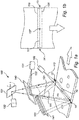
- Figure 1 schematically illustrates an apparatus 100 for inspecting a stream of matter 10.
- the arrows in Figure 1a and 1b illustrate the transport direction of the stream of matter, or the net direction of motion of said matter, or the feed direction.
- the apparatus 100 comprises a first light source 101, which is adapted to emit a first light beam 111 comprising wavelengths within a first wavelength range ( ⁇ 1a - ⁇ 1b ) for illuminating said stream of matter from side to side.
- the first light source is a line illumination which simultaneously illuminates said stream of matter 10 from one side 13 to the other 14.
- the apparatus 100 also comprises a second light source 102 adapted to emit a second light beam 112 comprising wavelengths within a second wavelength range ( ⁇ 2a - ⁇ 2b ), for illuminating said stream of matter at a second illuminated area 117.
- the second light source is a line illumination which simultaneously illuminates said stream of matter 10 from one side 13 to the other 14. Further any wavelength ( ⁇ 1 ) in said first wavelength range of said first light source is different from any wavelength ( ⁇ 2 ) in said second wavelength range of said second light source ( ⁇ 1b ⁇ ⁇ 2a or ⁇ 2b ⁇ ⁇ 1a ).
- the first light beam 111 is reflected by said stream of matter towards a beam splitting element 140.
- the beam splitting element 140 is arranged to receive said first light beam 111, after it has been reflected against said matter along a first optical axis 121; and arranged to receive said second light beam 112, after said second light beam has been reflected against said matter also along said first optical axis 121.
- the beam splitting element 140 e.g.
- a dichroic mirror is futher adapted to guide said reflected first light beam 111 towards a first detector 131; and to guide said reflected second light beam 112 towards said second detector 132 by redirecting one of said reflected first light beam and said reflected second light beam along a second optical axis 122 non-parallel said first optical axis 121. More specifically said scanning element 151 is arranged between said beam splitting element 140 and said second detector 132 to receive only said reflected second light beam of said reflected first and second light beams.
- first detector 131 is adapted to receive said first light beam 111 after it has been reflected against said stream of matter 10 at a first detection area 136; and said second detector 132 is adapted to receive said second light beam 112 after it has been reflected against said stream of matter 10 at a second detection area 137.
- a first scanning element 151 is arranged between said stream of matter 10 and said second detector 132 and being adapted to redirect said second detection area 137 from side to side across said stream of matter.
- Figure 1b illustrates the first illuminated area 116, or the area 116 illuminated by said first light source 101.
- the first light source is a line illumination comprising LED-lamps which simultaneaoulsy illuminates the whole width of the stream, and the first illuminated area is a rectangle extending from side to side across the stream of matter.
- the LED-lamps may be pulsed or continuous.
- the first detector 131 is a line detector or area detector (the sensors in the detector are arranged in a line or a matrix) adapted to simultaneoulsy detect the whole width of the stream of matter.
- the field of view 136 of said first detector or the first detection area 136 correspodns to a rectangle extending from side to side across the stream of matter.
- the first detection area 136 is within said first illuminated area 116.
- the area 117 illuminated by said second light source 102, or the second illuminated area 117 is also indicated in Figure 1b .
- the second light source is a line illumination comprising a laser
- the second illuminated area is line extending from side to side across the stream of matter.
- the laser may be pulsed or continuous.
- the second detector 132 is spectrometer adapted to sweepingly detect the whole width of the stream of matter.
- the field of view 137 of said second detector or the second detection area 137 corresponds to a spot.
- the field of view 137 of said second detector or the second detection area 137 is moved from side to side across the stream of matter by means of a scanning element 151, here a tilting mirror.
- said first and second light sources are adapted to illuminate the stream of matter both at the same time.
- said first and second light sources are adapted to illuminate the stream of matter consecutively, i.e. first said first light source is lit and thereafter said second light source is lit, and thereafter the lighting sequence is repeated over and over again.
- a combination of examples one and two is used, i.e. the light sources are sometimes lit simultaneously, and sometimes lit consecutively according to a predetermined illumination sequence.
- the first light source may be any suitable illumination and comprise e.g. a laser, light emitting diodes, fluorescent tubes or combination of these.
- the first light source may emit radiation in the ultra violet range (UV) visible range (VIS), near infrared range (NIR), or mid infrared range (MIR) or in a combination of these ranges.
- UV ultra violet range
- VIS visible range
- NIR near infrared range
- MIR mid infrared range
- the second light source may be any suitable illumination and comprise e.g. halogen lamps.
- the second light source may emit radiation in the ultra violet range (UV), visible range (VIS), near infrared range (NIR), or mid infrared range (MIR) or in a combination of these ranges.
- a filter element may be arranged between the first light source and the stream of matter, which filter element is e.g. selected such that it removes wavelengths emitted by said first light source which disturbs the second detector; additionally or alternatively a filter element may be arranged between the first light source and the stream of matter, which filter element is e.g. selected such that it removes wavelengths emitted by said first light source which disturbs the second detector.
- the wavelengths of said first wavelength range is shorter than the wavelengths of said second wavelength range.
- said second light source emits wavelengths not only in said second wavelength range but also within the interval of said first wavelength range and the cutting wavelength of said beam splitter, which wavelengths are distrubing to the measurements performed by using said first detector.
- a filter element may arranged between said second light source and said stream of matter, which filter element removes the wavelengths emitted by said second light source which is shorter than said cutting wavelength, or said filter element removes the wavelegnths which are within the interval of said first wavelength range and the cutting wavelength of said beam splitter. Hence, the second light source does not disturb the first detector.
- the wavelengths of said first wavelength range is shorter than the wavelengths of said second wavelength range.
- said first light source emits wavelengths not only in said first wavelength range but also within the interval of said second wavelength range and the cutting wavelength of said beam splitter, which wavelengths are distrubing to the measurements performed by using said second detector.
- a filter element may be arranged between said first light source and said stream of matter, which filter element removes the wavelengths emitted by said first light source which is longer than or eqal to said cutting wavelength, or said filter element removes the wavelegnths which are within the interval of said second wavelength range and the cutting wavelength of said beam splitter. Hence, the first light source does not disturb the second detector.
- Analogous solutions may be applied when the wavelengths of said first wavelength range is longer than the wavelengths of said second wavelength range.
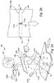
- the apparatus illustrated in Figures 2a and 2b is equal to the one described in relation to Figures 1a and 1b , except for the details mentioned below.
- the tilting mirror is replaced by a polygon mirror 151, which is arranged to rotate around its central axis, e.g. by means of a motor (not shown).
- the second illumination is not a line illumination but a spot illuminaton.
- the first light source 101 comprises two separate lamps 101a, 101b, arranged one on each side of the stream of matter. Both lamps illuminates substantially the same first illuminated area 116 on the stream of matter.
- the second light source 102 comprises two separate light sources 102a, 102b.
- the area 117a, 117b illuminated by said second light source 102, or the second illuminated area 117a, 117b is indicated in Figure 1b .
- the second light source is a point illumination comprising a laser, illuminating only a portion of said stream of matter.
- the laser may be pulsed or continuous.
- the redirecting element 151 is arranged to sweepingly move the second illuminated area 117a, 117b from side to side across said stream of matter.
- the second detector 132 is spectrometer adapted to sweepingly detect the whole width of the stream of matter.
- the field of view 137 of said second detector or the second detection area 137 corresponds to a spot.
- the field of view 137 of said second detector or the second detection area 137 may be moved from side to side across the stream of matter by means of a scanning element 151, here a polygon mirror.
- the second detection area 137 is within the area illuminated by said second light source 117a, 117b.
- said second light source 102 illuminates said stream of matter 10 at a second illuminated area 117a, 117b covering only a portion of the width of said stream of matter
- a redirecting element 151 is arranged to receive said second light beam 112a, 112b from said second light source 102 and is adapted to redirect said second light beam so as to move said first illuminated area 117a, 117b from side to side across said stream of matter, wherein preferbly said redirecting element and said first scanning element, described in relation to Figure 1a , is one an the same.
- the first light source comprises LEDs emitting white light, e.g. Z-Power LEDs being manufactured by Seol Semiconductor and emitting Pure White light; and in more detail belonging to e.g. the A0-A5, B0-B5 or C0-C5 binning described in more detail in the product specification, i.e. roughly within the CIE coordintates (0.3028, 0.3304) (0.3552, 0.3760) (0.3514, 0.3487) (0.3068, 0.3113) (0.3028, 0.3304).
- the LEDs simultaneously illuminates the stream of matter from side to side.
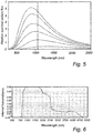
- the second light source is one of the halogen lamps, which spectrums are illustrated in Figure 5 .
- the top line is the spectral distribution of a lamp of 3 300 K
- the one below is the spectral distribution of a lamp of 3 200 K
- the one below that is the spectral distribution of a lamp of 2 800 K the one below that is the spectral distribution of a lamp of 2 500 K
- the bottom one is the spectral distribution of a lamp of 2 000 K.
- the second light source simultaneously illuminates the stream of matter from side to side.
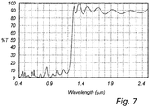
- a filter having the transmittance illustrated in Figure 6 i.e. a cut on wavelength at about 850 nm, is arranged between the second light source and the stream of matter.
- a dichroic mirror having a transmittance as illustrated in Figure 6 i.e. a cutting wavelength at about 1 200 nm, is selected as beam splitting element.
- the first detector is an RGB-camera and the second detector is a NIR spectrometer.
- the cutting wavelength (about 1 200 nm) of the spectrometer is also indicated in Figure 5 .
- first and second light sources When the first and second light sources are lit simultaneously, light from both light sources reaches the beam splitter and is divided into a first portion substantially consisting of wavelength lower than said cutting wavelength, and a second portion substantially consisting of wavelength longer than said cutting wavelength.
- the first portion is reflected by said beam splitter towards the first detector, and the second portion is transmitted by said beam splitter towards said second detector.
- substantially only light from said first light source is transmitted to said first detector
- substantially only light from said second light source is transmitted to said second detector.
- a major part of the energy content is constituted by wavelengths being shorter than the cutting wavelength, and a minor part of the energy content is constituted by wavelengths being longer than the cutting wavelength.
- more than 80 %, or more than 90 %, or more than 95 %, of the energy content is constituted by wavelengths being shoter than the cutting wavelength.
- a major part of the energy content is constituted by wavelengths being longer than the cutting wavelength, and a minor part of the energy content is constituted by wavelengths being shorter than the cutting wavelength.
- more than 80 %, or more than 90 %, or more than 95 %, of the energy content is constituted by wavelengths being longer than the cutting wavelength.
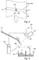
- An illumination of said stream of matter from side to side includes, but is not limited to, an illumination which is orthogonal to the transport direction of said stream of matter. As indicated in Figure 3 , an illumination of said stream of matter from side to side may be off-set from an orthogonal illumination by e.g. 25°.
- Figure 4 illustrates one application of the apparatus described above.
- Light reflected from a stream of matter is received by a beam splitting element 140, and split into two portions dependent on wavelength, and each portion is forwarded to a respective detector 131, 132.
- the objects 10 in the stream of matter are sorted into a first or a second container 431, 432 by use of a sorting apparatus 420 utilizing pressurized air. I.e. when an object is to be put in the right container a puff of air is emitted which pushes the object into the right container.
- a system comprising an apparatus arranged as described e.g. in relation to figures 1-3 .
- the stream of matter to be inspected comprises objects 10, and said system further comprises processing means 410 adapted to receive detection-data from said first detector and said second detector 131;132 and to transform this into sorting data; and removing means 420 adapted to receive sorting-data from said processing means and to remove objects from said stream of matter in dependence on said sorting-data.
- the sorting data may e.g. be indicative of wether the objects are to be put in the left or right container 431, 432.
- the objects that are removed could be directed to one common, or alternatively to several different spots dependent on the detection data.
- the illumination may be arranged beneath the stream of matter instead of above it, provided the coveyour is transparent.
- the conveyour may be replaced by a chute or a free fall path.
- the scanning element may be arranged between said beam splitter and said second detector, in a light path that is redirected by said beam splitting element, i.e. in a light path that is non-parallel with said first optical axis.
- additional light sources and detectors may be used, having a similar set up to what has been described above, i.e. where the light passes the dichroic mirror before reaching the detector.
- the combinations of light souces and detectors can be choosen freely, as long as the principles described herein are employed.
Landscapes
- Life Sciences & Earth Sciences (AREA)
- Health & Medical Sciences (AREA)
- General Health & Medical Sciences (AREA)
- Chemical & Material Sciences (AREA)
- Analytical Chemistry (AREA)
- Biochemistry (AREA)
- Physics & Mathematics (AREA)
- General Physics & Mathematics (AREA)
- Immunology (AREA)
- Pathology (AREA)
- Engineering & Computer Science (AREA)
- Biomedical Technology (AREA)
- Molecular Biology (AREA)
- Investigating Materials By The Use Of Optical Means Adapted For Particular Applications (AREA)
- Investigating Or Analysing Materials By Optical Means (AREA)
Priority Applications (2)
| Application Number | Priority Date | Filing Date | Title |
|---|---|---|---|
| PL14792832T PL3066456T3 (pl) | 2013-11-04 | 2014-11-03 | Urządzenie kontrolne |
| EP14792832.9A EP3066456B1 (en) | 2013-11-04 | 2014-11-03 | Inspection apparatus |
Applications Claiming Priority (3)
| Application Number | Priority Date | Filing Date | Title |
|---|---|---|---|
| EP13191395 | 2013-11-04 | ||
| EP14792832.9A EP3066456B1 (en) | 2013-11-04 | 2014-11-03 | Inspection apparatus |
| PCT/EP2014/073578 WO2015063300A1 (en) | 2013-11-04 | 2014-11-03 | Inspection apparatus |
Publications (2)
| Publication Number | Publication Date |
|---|---|
| EP3066456A1 EP3066456A1 (en) | 2016-09-14 |
| EP3066456B1 true EP3066456B1 (en) | 2020-06-03 |
Family
ID=49546270
Family Applications (1)
| Application Number | Title | Priority Date | Filing Date |
|---|---|---|---|
| EP14792832.9A Active EP3066456B1 (en) | 2013-11-04 | 2014-11-03 | Inspection apparatus |
Country Status (16)
| Country | Link |
|---|---|
| US (1) | US9575005B2 (enExample) |
| EP (1) | EP3066456B1 (enExample) |
| JP (1) | JP6668249B2 (enExample) |
| CN (1) | CN105874321B (enExample) |
| AU (1) | AU2014343597B2 (enExample) |
| BR (1) | BR112016009951B1 (enExample) |
| CA (1) | CA2928878C (enExample) |
| CL (1) | CL2016001058A1 (enExample) |
| ES (1) | ES2811601T3 (enExample) |
| MX (1) | MX360408B (enExample) |
| PE (1) | PE20160964A1 (enExample) |
| PL (1) | PL3066456T3 (enExample) |
| RU (1) | RU2664793C2 (enExample) |
| SA (1) | SA516371056B1 (enExample) |
| UA (1) | UA121305C2 (enExample) |
| WO (1) | WO2015063300A1 (enExample) |
Families Citing this family (28)
| Publication number | Priority date | Publication date | Assignee | Title |
|---|---|---|---|---|
| US10363582B2 (en) | 2016-01-15 | 2019-07-30 | Key Technology, Inc. | Method and apparatus for sorting |
| US9266148B2 (en) | 2014-06-27 | 2016-02-23 | Key Technology, Inc. | Method and apparatus for sorting |
| US10195647B2 (en) | 2016-01-15 | 2019-02-05 | Key Technology, Inc | Method and apparatus for sorting |
| EP3196634A1 (en) * | 2016-01-22 | 2017-07-26 | Buhler Sortex Ltd. | Inspection apparatus |
| FR3048369B1 (fr) * | 2016-03-01 | 2018-03-02 | Pellenc Selective Technologies | Machine et procede d'inspection d'objets defilant en flux |
| EP3263233A1 (en) * | 2016-06-28 | 2018-01-03 | Buhler Sortex Ltd. | Illumination devices |
| AT15723U1 (de) * | 2016-08-30 | 2018-04-15 | Binder Co Ag | Vorrichtung zum Detektieren von Objekten in einem Materialstrom |
| US10197504B2 (en) * | 2016-10-10 | 2019-02-05 | Altria Client Services Llc | Method and system of detecting foreign materials within an agricultural product stream |
| PL3529593T3 (pl) | 2016-10-24 | 2023-11-20 | Tomra Sorting Gmbh | Sposób i system do wykrywania sygnatury diamentu |
| EP3315216A1 (en) | 2016-10-28 | 2018-05-02 | Metso Sweden Ab | Detection system |
| WO2018205026A1 (en) | 2017-05-11 | 2018-11-15 | 6511660 Canada Inc. | Systems and methods for spectral identification and optical sorting of materials |
| TWI662261B (zh) * | 2018-01-17 | 2019-06-11 | 國立交通大學 | 同軸異質整合高光譜系統 |
| CN110208223B (zh) * | 2018-02-28 | 2025-02-25 | 中石化石油工程技术服务股份有限公司 | 地质录井岩屑传动分析装置 |
| CN108548786B (zh) * | 2018-03-08 | 2023-09-05 | 青岛农业大学 | 一种使用多面转镜光谱检测花生黄曲霉毒素的装置与方法 |
| DE102018210015B4 (de) * | 2018-06-20 | 2020-04-02 | Fraunhofer-Gesellschaft zur Förderung der angewandten Forschung e.V. | Vorrichtung und Verfahren zur Sortierung von pulverförmigem, partikelförmigem, granulatförmigem oder stückförmigem Material |
| WO2020057924A1 (en) * | 2018-09-21 | 2020-03-26 | Asml Netherlands B.V. | Radiation system |
| AU2019386256B2 (en) | 2018-11-27 | 2024-12-19 | Suez International | Method for separating and classifying waste, in particular packaging |
| NL2023271B1 (en) * | 2019-06-06 | 2020-12-22 | Aweta G&P B V | Apparatus and method for determining a property of products |
| JP7376380B2 (ja) * | 2020-02-13 | 2023-11-08 | 大王製紙株式会社 | 廃プラスチックの選別装置 |
| EP4162256B1 (en) * | 2020-06-08 | 2024-10-16 | TOMRA Sorting GmbH | Apparatus for detecting matter |
| JP7493443B2 (ja) * | 2020-12-21 | 2024-05-31 | 株式会社クボタ | 色彩選別機 |
| US12083560B2 (en) * | 2021-11-01 | 2024-09-10 | Tianjin University Of Commerce | Sorting-based garbage classification method and device |
| US20250018433A1 (en) * | 2021-12-07 | 2025-01-16 | Tomra Sorting Gmbh | Apparatus for illuminating matter |
| JP7562597B2 (ja) * | 2022-05-12 | 2024-10-07 | キヤノン株式会社 | 識別装置 |
| EP4689617A1 (en) * | 2023-04-04 | 2026-02-11 | TOMRA Sorting GmbH | Rgb camera scanned illumination |
| WO2025021551A1 (en) | 2023-07-24 | 2025-01-30 | Tomra Sorting Gmbh | Sorting with automatic learning |
| EP4729931A1 (en) * | 2023-10-17 | 2026-04-22 | Hamamatsu Photonics K.K. | Inspection device |
| WO2026012614A1 (en) | 2024-07-12 | 2026-01-15 | Tomra Sorting Gmbh | Inspecting items in a stream of items by means of a classifiers |
Family Cites Families (18)
| Publication number | Priority date | Publication date | Assignee | Title |
|---|---|---|---|---|
| US4723659A (en) * | 1985-06-28 | 1988-02-09 | Supernova Systems, Inc. | Apparatus for detecting impurities in translucent bodies |
| US5462176A (en) * | 1994-06-03 | 1995-10-31 | Brown & Williamson Tobacco Corporation | Latex detection system |
| JP3454575B2 (ja) * | 1994-07-14 | 2003-10-06 | オリンパス光学工業株式会社 | 走査型光学測定装置 |
| US6060677A (en) * | 1994-08-19 | 2000-05-09 | Tiedemanns-Jon H. Andresen Ans | Determination of characteristics of material |
| BE1011076A3 (nl) * | 1997-03-28 | 1999-04-06 | Ruymen Marc | Werkwijze en inrichting voor het detecteren van onregelmatigheden in een produkt. |
| DE19717488C2 (de) * | 1997-04-25 | 2003-05-15 | Baumer Optronic Gmbh | Vorrichtung zur Inspektion der Oberfläche von Objekten |
| JPH11337504A (ja) * | 1998-05-26 | 1999-12-10 | Central Glass Co Ltd | ガラス板の欠陥識別検査方法および装置 |
| ES2276670T3 (es) | 1999-03-19 | 2007-07-01 | Titech Visionsort As | Inspeccion de materiales. |
| US6633338B1 (en) * | 1999-04-27 | 2003-10-14 | Gsi Lumonics, Inc. | Programmable illuminator for vision system |
| US6437168B1 (en) * | 2000-09-05 | 2002-08-20 | Nippon Shokubai Co., Ltd. | Method for production of aromatic fluorine compound |
| JP2003232624A (ja) * | 2002-02-12 | 2003-08-22 | Olympus Optical Co Ltd | 欠陥検査装置 |
| WO2008027930A2 (en) * | 2006-08-28 | 2008-03-06 | Thermo Electron Scientific Instruments Llc | Spectroscope with spatial resolution control |
| JP2008302314A (ja) * | 2007-06-08 | 2008-12-18 | Satake Corp | 光学式米粒選別機 |
| CA2697636C (en) | 2007-09-03 | 2015-11-03 | Belgian Electronic Sorting Technology, N.V. | Sorting device with a broad spectrum light source and according method |
| JP2009168747A (ja) * | 2008-01-18 | 2009-07-30 | Sumitomo Electric Ind Ltd | 食品検査方法及び食品検査装置 |
| CN202281746U (zh) * | 2010-03-06 | 2012-06-20 | 伊鲁米那股份有限公司 | 检测来自样品光信号的测定设备及其光学组件和光学系统 |
| US9128036B2 (en) * | 2011-03-21 | 2015-09-08 | Federal-Mogul Corporation | Multi-spectral imaging system and method of surface inspection therewith |
| NO336441B1 (no) * | 2012-01-24 | 2015-08-17 | Tomra Sorting As | Anordning, system og fremgangsmåte for optisk detektering av materie |
-
2014
- 2014-11-03 CA CA2928878A patent/CA2928878C/en active Active
- 2014-11-03 CN CN201480068050.1A patent/CN105874321B/zh active Active
- 2014-11-03 EP EP14792832.9A patent/EP3066456B1/en active Active
- 2014-11-03 ES ES14792832T patent/ES2811601T3/es active Active
- 2014-11-03 BR BR112016009951-6A patent/BR112016009951B1/pt active IP Right Grant
- 2014-11-03 MX MX2016005836A patent/MX360408B/es active IP Right Grant
- 2014-11-03 JP JP2016551010A patent/JP6668249B2/ja active Active
- 2014-11-03 AU AU2014343597A patent/AU2014343597B2/en active Active
- 2014-11-03 UA UAA201604913A patent/UA121305C2/uk unknown
- 2014-11-03 US US15/033,367 patent/US9575005B2/en active Active
- 2014-11-03 RU RU2016119494A patent/RU2664793C2/ru active
- 2014-11-03 WO PCT/EP2014/073578 patent/WO2015063300A1/en not_active Ceased
- 2014-11-03 PE PE2016000594A patent/PE20160964A1/es unknown
- 2014-11-03 PL PL14792832T patent/PL3066456T3/pl unknown
-
2016
- 2016-05-03 CL CL2016001058A patent/CL2016001058A1/es unknown
- 2016-05-04 SA SA516371056A patent/SA516371056B1/ar unknown
Non-Patent Citations (1)
| Title |
|---|
| None * |
Also Published As
| Publication number | Publication date |
|---|---|
| US9575005B2 (en) | 2017-02-21 |
| CN105874321A (zh) | 2016-08-17 |
| JP2016540996A (ja) | 2016-12-28 |
| CN105874321B (zh) | 2019-06-28 |
| PE20160964A1 (es) | 2016-10-16 |
| EP3066456A1 (en) | 2016-09-14 |
| RU2016119494A (ru) | 2017-12-11 |
| CL2016001058A1 (es) | 2016-12-02 |
| UA121305C2 (uk) | 2020-05-12 |
| SA516371056B1 (ar) | 2018-02-25 |
| PL3066456T3 (pl) | 2020-11-16 |
| CA2928878A1 (en) | 2015-05-07 |
| US20160252461A1 (en) | 2016-09-01 |
| MX2016005836A (es) | 2016-12-02 |
| AU2014343597A1 (en) | 2016-05-19 |
| WO2015063300A1 (en) | 2015-05-07 |
| RU2016119494A3 (enExample) | 2018-05-15 |
| BR112016009951B1 (pt) | 2020-12-01 |
| CA2928878C (en) | 2020-06-23 |
| ES2811601T3 (es) | 2021-03-12 |
| RU2664793C2 (ru) | 2018-08-22 |
| MX360408B (es) | 2018-10-29 |
| JP6668249B2 (ja) | 2020-03-18 |
| AU2014343597B2 (en) | 2019-09-12 |
Similar Documents
| Publication | Publication Date | Title |
|---|---|---|
| EP3066456B1 (en) | Inspection apparatus | |
| ES2746882T3 (es) | Procedimiento, unidad captadora y máquina para detectar defectos de "puntas de azúcar" en patatas | |
| KR102545082B1 (ko) | 대상물의 흐름을 검사하기 위한 기계 및 방법 | |
| EP3063531B1 (en) | Method and apparatus for detecting matter | |
| ES3004941T3 (en) | Apparatus for detecting matter | |
| KR102395039B1 (ko) | 벌크재 검사장치 및 방법 | |
| ES3055663T3 (en) | Material identification apparatus and method | |
| US9568438B1 (en) | Single-camera angled conveyance imaging method and apparatus for whole-surface inspection of rotating objects | |
| WO2019086727A1 (es) | Dispositivo de inspección y caracterización de productos | |
| JP2005326220A (ja) | 異物検査装置 | |
| JP7065755B2 (ja) | 物品検査装置 | |
| JP2025500756A (ja) | 物質を照明するための装置 | |
| US20250244255A1 (en) | Scanning of objects | |
| JP2021092461A (ja) | 青果物の内部品質検査装置 | |
| WO2013117769A1 (en) | Illumination and detection system |
Legal Events
| Date | Code | Title | Description |
|---|---|---|---|
| PUAI | Public reference made under article 153(3) epc to a published international application that has entered the european phase |
Free format text: ORIGINAL CODE: 0009012 |
|
| 17P | Request for examination filed |
Effective date: 20160603 |
|
| AK | Designated contracting states |
Kind code of ref document: A1 Designated state(s): AL AT BE BG CH CY CZ DE DK EE ES FI FR GB GR HR HU IE IS IT LI LT LU LV MC MK MT NL NO PL PT RO RS SE SI SK SM TR |
|
| AX | Request for extension of the european patent |
Extension state: BA ME |
|
| DAX | Request for extension of the european patent (deleted) | ||
| GRAP | Despatch of communication of intention to grant a patent |
Free format text: ORIGINAL CODE: EPIDOSNIGR1 |
|
| STAA | Information on the status of an ep patent application or granted ep patent |
Free format text: STATUS: GRANT OF PATENT IS INTENDED |
|
| INTG | Intention to grant announced |
Effective date: 20200113 |
|
| GRAS | Grant fee paid |
Free format text: ORIGINAL CODE: EPIDOSNIGR3 |
|
| GRAA | (expected) grant |
Free format text: ORIGINAL CODE: 0009210 |
|
| STAA | Information on the status of an ep patent application or granted ep patent |
Free format text: STATUS: THE PATENT HAS BEEN GRANTED |
|
| AK | Designated contracting states |
Kind code of ref document: B1 Designated state(s): AL AT BE BG CH CY CZ DE DK EE ES FI FR GB GR HR HU IE IS IT LI LT LU LV MC MK MT NL NO PL PT RO RS SE SI SK SM TR |
|
| REG | Reference to a national code |
Ref country code: GB Ref legal event code: FG4D |
|
| REG | Reference to a national code |
Ref country code: CH Ref legal event code: EP Ref country code: AT Ref legal event code: REF Ref document number: 1277515 Country of ref document: AT Kind code of ref document: T Effective date: 20200615 |
|
| REG | Reference to a national code |
Ref country code: DE Ref legal event code: R096 Ref document number: 602014066267 Country of ref document: DE |
|
| REG | Reference to a national code |
Ref country code: NL Ref legal event code: FP |
|
| REG | Reference to a national code |
Ref country code: GR Ref legal event code: EP Ref document number: 20200402439 Country of ref document: GR Effective date: 20201014 |
|
| REG | Reference to a national code |
Ref country code: LT Ref legal event code: MG4D |
|
| PG25 | Lapsed in a contracting state [announced via postgrant information from national office to epo] |
Ref country code: NO Free format text: LAPSE BECAUSE OF FAILURE TO SUBMIT A TRANSLATION OF THE DESCRIPTION OR TO PAY THE FEE WITHIN THE PRESCRIBED TIME-LIMIT Effective date: 20200903 Ref country code: FI Free format text: LAPSE BECAUSE OF FAILURE TO SUBMIT A TRANSLATION OF THE DESCRIPTION OR TO PAY THE FEE WITHIN THE PRESCRIBED TIME-LIMIT Effective date: 20200603 Ref country code: SE Free format text: LAPSE BECAUSE OF FAILURE TO SUBMIT A TRANSLATION OF THE DESCRIPTION OR TO PAY THE FEE WITHIN THE PRESCRIBED TIME-LIMIT Effective date: 20200603 Ref country code: LT Free format text: LAPSE BECAUSE OF FAILURE TO SUBMIT A TRANSLATION OF THE DESCRIPTION OR TO PAY THE FEE WITHIN THE PRESCRIBED TIME-LIMIT Effective date: 20200603 |
|
| PG25 | Lapsed in a contracting state [announced via postgrant information from national office to epo] |
Ref country code: BG Free format text: LAPSE BECAUSE OF FAILURE TO SUBMIT A TRANSLATION OF THE DESCRIPTION OR TO PAY THE FEE WITHIN THE PRESCRIBED TIME-LIMIT Effective date: 20200903 Ref country code: RS Free format text: LAPSE BECAUSE OF FAILURE TO SUBMIT A TRANSLATION OF THE DESCRIPTION OR TO PAY THE FEE WITHIN THE PRESCRIBED TIME-LIMIT Effective date: 20200603 Ref country code: LV Free format text: LAPSE BECAUSE OF FAILURE TO SUBMIT A TRANSLATION OF THE DESCRIPTION OR TO PAY THE FEE WITHIN THE PRESCRIBED TIME-LIMIT Effective date: 20200603 Ref country code: HR Free format text: LAPSE BECAUSE OF FAILURE TO SUBMIT A TRANSLATION OF THE DESCRIPTION OR TO PAY THE FEE WITHIN THE PRESCRIBED TIME-LIMIT Effective date: 20200603 |
|
| REG | Reference to a national code |
Ref country code: SK Ref legal event code: T3 Ref document number: E 35246 Country of ref document: SK |
|
| PG25 | Lapsed in a contracting state [announced via postgrant information from national office to epo] |
Ref country code: AL Free format text: LAPSE BECAUSE OF FAILURE TO SUBMIT A TRANSLATION OF THE DESCRIPTION OR TO PAY THE FEE WITHIN THE PRESCRIBED TIME-LIMIT Effective date: 20200603 |
|
| PG25 | Lapsed in a contracting state [announced via postgrant information from national office to epo] |
Ref country code: EE Free format text: LAPSE BECAUSE OF FAILURE TO SUBMIT A TRANSLATION OF THE DESCRIPTION OR TO PAY THE FEE WITHIN THE PRESCRIBED TIME-LIMIT Effective date: 20200603 Ref country code: CZ Free format text: LAPSE BECAUSE OF FAILURE TO SUBMIT A TRANSLATION OF THE DESCRIPTION OR TO PAY THE FEE WITHIN THE PRESCRIBED TIME-LIMIT Effective date: 20200603 Ref country code: SM Free format text: LAPSE BECAUSE OF FAILURE TO SUBMIT A TRANSLATION OF THE DESCRIPTION OR TO PAY THE FEE WITHIN THE PRESCRIBED TIME-LIMIT Effective date: 20200603 Ref country code: PT Free format text: LAPSE BECAUSE OF FAILURE TO SUBMIT A TRANSLATION OF THE DESCRIPTION OR TO PAY THE FEE WITHIN THE PRESCRIBED TIME-LIMIT Effective date: 20201006 Ref country code: RO Free format text: LAPSE BECAUSE OF FAILURE TO SUBMIT A TRANSLATION OF THE DESCRIPTION OR TO PAY THE FEE WITHIN THE PRESCRIBED TIME-LIMIT Effective date: 20200603 |
|
| PG25 | Lapsed in a contracting state [announced via postgrant information from national office to epo] |
Ref country code: IS Free format text: LAPSE BECAUSE OF FAILURE TO SUBMIT A TRANSLATION OF THE DESCRIPTION OR TO PAY THE FEE WITHIN THE PRESCRIBED TIME-LIMIT Effective date: 20201003 |
|
| REG | Reference to a national code |
Ref country code: DE Ref legal event code: R097 Ref document number: 602014066267 Country of ref document: DE |
|
| REG | Reference to a national code |
Ref country code: ES Ref legal event code: FG2A Ref document number: 2811601 Country of ref document: ES Kind code of ref document: T3 Effective date: 20210312 |
|
| REG | Reference to a national code |
Ref country code: AT Ref legal event code: UEP Ref document number: 1277515 Country of ref document: AT Kind code of ref document: T Effective date: 20200603 |
|
| PLBE | No opposition filed within time limit |
Free format text: ORIGINAL CODE: 0009261 |
|
| STAA | Information on the status of an ep patent application or granted ep patent |
Free format text: STATUS: NO OPPOSITION FILED WITHIN TIME LIMIT |
|
| PG25 | Lapsed in a contracting state [announced via postgrant information from national office to epo] |
Ref country code: DK Free format text: LAPSE BECAUSE OF FAILURE TO SUBMIT A TRANSLATION OF THE DESCRIPTION OR TO PAY THE FEE WITHIN THE PRESCRIBED TIME-LIMIT Effective date: 20200603 |
|
| 26N | No opposition filed |
Effective date: 20210304 |
|
| PG25 | Lapsed in a contracting state [announced via postgrant information from national office to epo] |
Ref country code: SI Free format text: LAPSE BECAUSE OF FAILURE TO SUBMIT A TRANSLATION OF THE DESCRIPTION OR TO PAY THE FEE WITHIN THE PRESCRIBED TIME-LIMIT Effective date: 20200603 |
|
| PG25 | Lapsed in a contracting state [announced via postgrant information from national office to epo] |
Ref country code: MC Free format text: LAPSE BECAUSE OF FAILURE TO SUBMIT A TRANSLATION OF THE DESCRIPTION OR TO PAY THE FEE WITHIN THE PRESCRIBED TIME-LIMIT Effective date: 20200603 |
|
| PG25 | Lapsed in a contracting state [announced via postgrant information from national office to epo] |
Ref country code: LU Free format text: LAPSE BECAUSE OF NON-PAYMENT OF DUE FEES Effective date: 20201103 |
|
| PG25 | Lapsed in a contracting state [announced via postgrant information from national office to epo] |
Ref country code: MT Free format text: LAPSE BECAUSE OF FAILURE TO SUBMIT A TRANSLATION OF THE DESCRIPTION OR TO PAY THE FEE WITHIN THE PRESCRIBED TIME-LIMIT Effective date: 20200603 Ref country code: CY Free format text: LAPSE BECAUSE OF FAILURE TO SUBMIT A TRANSLATION OF THE DESCRIPTION OR TO PAY THE FEE WITHIN THE PRESCRIBED TIME-LIMIT Effective date: 20200603 |
|
| PG25 | Lapsed in a contracting state [announced via postgrant information from national office to epo] |
Ref country code: MK Free format text: LAPSE BECAUSE OF FAILURE TO SUBMIT A TRANSLATION OF THE DESCRIPTION OR TO PAY THE FEE WITHIN THE PRESCRIBED TIME-LIMIT Effective date: 20200603 |
|
| PGFP | Annual fee paid to national office [announced via postgrant information from national office to epo] |
Ref country code: NL Payment date: 20251015 Year of fee payment: 12 |
|
| REG | Reference to a national code |
Ref country code: CH Ref legal event code: U11 Free format text: ST27 STATUS EVENT CODE: U-0-0-U10-U11 (AS PROVIDED BY THE NATIONAL OFFICE) Effective date: 20251201 |
|
| PGFP | Annual fee paid to national office [announced via postgrant information from national office to epo] |
Ref country code: DE Payment date: 20251007 Year of fee payment: 12 |
|
| PGFP | Annual fee paid to national office [announced via postgrant information from national office to epo] |
Ref country code: GB Payment date: 20251016 Year of fee payment: 12 |
|
| PGFP | Annual fee paid to national office [announced via postgrant information from national office to epo] |
Ref country code: AT Payment date: 20251027 Year of fee payment: 12 |
|
| PGFP | Annual fee paid to national office [announced via postgrant information from national office to epo] |
Ref country code: IT Payment date: 20251022 Year of fee payment: 12 |
|
| PGFP | Annual fee paid to national office [announced via postgrant information from national office to epo] |
Ref country code: FR Payment date: 20251023 Year of fee payment: 12 |
|
| PGFP | Annual fee paid to national office [announced via postgrant information from national office to epo] |
Ref country code: TR Payment date: 20251030 Year of fee payment: 12 Ref country code: GR Payment date: 20251014 Year of fee payment: 12 Ref country code: BE Payment date: 20251015 Year of fee payment: 12 |
|
| PGFP | Annual fee paid to national office [announced via postgrant information from national office to epo] |
Ref country code: CH Payment date: 20251201 Year of fee payment: 12 |
|
| PGFP | Annual fee paid to national office [announced via postgrant information from national office to epo] |
Ref country code: IE Payment date: 20251009 Year of fee payment: 12 |
|
| PGFP | Annual fee paid to national office [announced via postgrant information from national office to epo] |
Ref country code: PL Payment date: 20251014 Year of fee payment: 12 |
|
| PGFP | Annual fee paid to national office [announced via postgrant information from national office to epo] |
Ref country code: SK Payment date: 20251013 Year of fee payment: 12 |
|
| PGFP | Annual fee paid to national office [announced via postgrant information from national office to epo] |
Ref country code: ES Payment date: 20251212 Year of fee payment: 12 |