EP3066403B1 - Tragbares eisfass - Google Patents
Tragbares eisfass Download PDFInfo
- Publication number
- EP3066403B1 EP3066403B1 EP14805728.4A EP14805728A EP3066403B1 EP 3066403 B1 EP3066403 B1 EP 3066403B1 EP 14805728 A EP14805728 A EP 14805728A EP 3066403 B1 EP3066403 B1 EP 3066403B1
- Authority
- EP
- European Patent Office
- Prior art keywords
- barrel
- wall
- portable ice
- exterior
- sections
- Prior art date
- Legal status (The legal status is an assumption and is not a legal conclusion. Google has not performed a legal analysis and makes no representation as to the accuracy of the status listed.)
- Active
Links
Images














Classifications
-
- F—MECHANICAL ENGINEERING; LIGHTING; HEATING; WEAPONS; BLASTING
- F25—REFRIGERATION OR COOLING; COMBINED HEATING AND REFRIGERATION SYSTEMS; HEAT PUMP SYSTEMS; MANUFACTURE OR STORAGE OF ICE; LIQUEFACTION SOLIDIFICATION OF GASES
- F25C—PRODUCING, WORKING OR HANDLING ICE
- F25C5/00—Working or handling ice
- F25C5/18—Storing ice
- F25C5/182—Ice bins therefor
-
- F—MECHANICAL ENGINEERING; LIGHTING; HEATING; WEAPONS; BLASTING
- F25—REFRIGERATION OR COOLING; COMBINED HEATING AND REFRIGERATION SYSTEMS; HEAT PUMP SYSTEMS; MANUFACTURE OR STORAGE OF ICE; LIQUEFACTION SOLIDIFICATION OF GASES
- F25D—REFRIGERATORS; COLD ROOMS; ICE-BOXES; COOLING OR FREEZING APPARATUS NOT OTHERWISE PROVIDED FOR
- F25D3/00—Devices using other cold materials; Devices using cold-storage bodies
- F25D3/02—Devices using other cold materials; Devices using cold-storage bodies using ice, e.g. ice-boxes
- F25D3/06—Movable containers
-
- A—HUMAN NECESSITIES
- A47—FURNITURE; DOMESTIC ARTICLES OR APPLIANCES; COFFEE MILLS; SPICE MILLS; SUCTION CLEANERS IN GENERAL
- A47F—SPECIAL FURNITURE, FITTINGS, OR ACCESSORIES FOR SHOPS, STOREHOUSES, BARS, RESTAURANTS OR THE LIKE; PAYING COUNTERS
- A47F3/00—Show cases or show cabinets
- A47F3/004—Show cases or show cabinets adjustable, foldable or easily dismountable
-
- B—PERFORMING OPERATIONS; TRANSPORTING
- B65—CONVEYING; PACKING; STORING; HANDLING THIN OR FILAMENTARY MATERIAL
- B65D—CONTAINERS FOR STORAGE OR TRANSPORT OF ARTICLES OR MATERIALS, e.g. BAGS, BARRELS, BOTTLES, BOXES, CANS, CARTONS, CRATES, DRUMS, JARS, TANKS, HOPPERS, FORWARDING CONTAINERS; ACCESSORIES, CLOSURES, OR FITTINGS THEREFOR; PACKAGING ELEMENTS; PACKAGES
- B65D11/00—Containers having bodies formed by interconnecting or uniting two or more rigid, or substantially rigid, components made wholly or mainly of plastics material
- B65D11/18—Containers having bodies formed by interconnecting or uniting two or more rigid, or substantially rigid, components made wholly or mainly of plastics material collapsible, i.e. with walls hinged together or detachably connected
- B65D11/1866—Containers having bodies formed by interconnecting or uniting two or more rigid, or substantially rigid, components made wholly or mainly of plastics material collapsible, i.e. with walls hinged together or detachably connected with detachable components
- B65D11/1873—Containers having bodies formed by interconnecting or uniting two or more rigid, or substantially rigid, components made wholly or mainly of plastics material collapsible, i.e. with walls hinged together or detachably connected with detachable components all walls are detached from each other to collapse the container
-
- B—PERFORMING OPERATIONS; TRANSPORTING
- B65—CONVEYING; PACKING; STORING; HANDLING THIN OR FILAMENTARY MATERIAL
- B65D—CONTAINERS FOR STORAGE OR TRANSPORT OF ARTICLES OR MATERIALS, e.g. BAGS, BARRELS, BOTTLES, BOXES, CANS, CARTONS, CRATES, DRUMS, JARS, TANKS, HOPPERS, FORWARDING CONTAINERS; ACCESSORIES, CLOSURES, OR FITTINGS THEREFOR; PACKAGING ELEMENTS; PACKAGES
- B65D81/00—Containers, packaging elements, or packages, for contents presenting particular transport or storage problems, or adapted to be used for non-packaging purposes after removal of contents
- B65D81/38—Containers, packaging elements, or packages, for contents presenting particular transport or storage problems, or adapted to be used for non-packaging purposes after removal of contents with thermal insulation
- B65D81/3802—Containers, packaging elements, or packages, for contents presenting particular transport or storage problems, or adapted to be used for non-packaging purposes after removal of contents with thermal insulation rigid container in the form of a barrel or vat
- B65D81/3806—Containers, packaging elements, or packages, for contents presenting particular transport or storage problems, or adapted to be used for non-packaging purposes after removal of contents with thermal insulation rigid container in the form of a barrel or vat formed with double walls, i.e. hollow
-
- F—MECHANICAL ENGINEERING; LIGHTING; HEATING; WEAPONS; BLASTING
- F25—REFRIGERATION OR COOLING; COMBINED HEATING AND REFRIGERATION SYSTEMS; HEAT PUMP SYSTEMS; MANUFACTURE OR STORAGE OF ICE; LIQUEFACTION SOLIDIFICATION OF GASES
- F25D—REFRIGERATORS; COLD ROOMS; ICE-BOXES; COOLING OR FREEZING APPARATUS NOT OTHERWISE PROVIDED FOR
- F25D2201/00—Insulation
- F25D2201/10—Insulation with respect to heat
-
- F—MECHANICAL ENGINEERING; LIGHTING; HEATING; WEAPONS; BLASTING
- F25—REFRIGERATION OR COOLING; COMBINED HEATING AND REFRIGERATION SYSTEMS; HEAT PUMP SYSTEMS; MANUFACTURE OR STORAGE OF ICE; LIQUEFACTION SOLIDIFICATION OF GASES
- F25D—REFRIGERATORS; COLD ROOMS; ICE-BOXES; COOLING OR FREEZING APPARATUS NOT OTHERWISE PROVIDED FOR
- F25D2303/00—Details of devices using other cold materials; Details of devices using cold-storage bodies
- F25D2303/08—Devices using cold storage material, i.e. ice or other freezable liquid
- F25D2303/081—Devices using cold storage material, i.e. ice or other freezable liquid using ice cubes or crushed ice
-
- F—MECHANICAL ENGINEERING; LIGHTING; HEATING; WEAPONS; BLASTING
- F25—REFRIGERATION OR COOLING; COMBINED HEATING AND REFRIGERATION SYSTEMS; HEAT PUMP SYSTEMS; MANUFACTURE OR STORAGE OF ICE; LIQUEFACTION SOLIDIFICATION OF GASES
- F25D—REFRIGERATORS; COLD ROOMS; ICE-BOXES; COOLING OR FREEZING APPARATUS NOT OTHERWISE PROVIDED FOR
- F25D2323/00—General constructional features not provided for in other groups of this subclass
- F25D2323/06—Details of walls not otherwise covered
- F25D2323/061—Collapsible walls
-
- F—MECHANICAL ENGINEERING; LIGHTING; HEATING; WEAPONS; BLASTING
- F25—REFRIGERATION OR COOLING; COMBINED HEATING AND REFRIGERATION SYSTEMS; HEAT PUMP SYSTEMS; MANUFACTURE OR STORAGE OF ICE; LIQUEFACTION SOLIDIFICATION OF GASES
- F25D—REFRIGERATORS; COLD ROOMS; ICE-BOXES; COOLING OR FREEZING APPARATUS NOT OTHERWISE PROVIDED FOR
- F25D2400/00—General features of, or devices for refrigerators, cold rooms, ice-boxes, or for cooling or freezing apparatus not covered by any other subclass
- F25D2400/12—Portable refrigerators
-
- F—MECHANICAL ENGINEERING; LIGHTING; HEATING; WEAPONS; BLASTING
- F25—REFRIGERATION OR COOLING; COMBINED HEATING AND REFRIGERATION SYSTEMS; HEAT PUMP SYSTEMS; MANUFACTURE OR STORAGE OF ICE; LIQUEFACTION SOLIDIFICATION OF GASES
- F25D—REFRIGERATORS; COLD ROOMS; ICE-BOXES; COOLING OR FREEZING APPARATUS NOT OTHERWISE PROVIDED FOR
- F25D2400/00—General features of, or devices for refrigerators, cold rooms, ice-boxes, or for cooling or freezing apparatus not covered by any other subclass
- F25D2400/32—Removal, transportation or shipping of refrigerating devices from one location to another
-
- F—MECHANICAL ENGINEERING; LIGHTING; HEATING; WEAPONS; BLASTING
- F25—REFRIGERATION OR COOLING; COMBINED HEATING AND REFRIGERATION SYSTEMS; HEAT PUMP SYSTEMS; MANUFACTURE OR STORAGE OF ICE; LIQUEFACTION SOLIDIFICATION OF GASES
- F25D—REFRIGERATORS; COLD ROOMS; ICE-BOXES; COOLING OR FREEZING APPARATUS NOT OTHERWISE PROVIDED FOR
- F25D2400/00—General features of, or devices for refrigerators, cold rooms, ice-boxes, or for cooling or freezing apparatus not covered by any other subclass
- F25D2400/38—Refrigerating devices characterised by wheels
Definitions
- the invention relates generally to a modular ice barrel that is shipped in component form and minimizes shipping volume. Once the ice barrel is delivered to the final destination, individuals can expediently assemble the components. As a result of the reduced volume and assembly capability, shipping and transportation costs are minimized and greater amounts of ice barrels delivered in a single shipment can be increased.
- Ice barrels can be shipped fully assembled to the point of use from a distant location. This can result in empty space in the interior cavity of the barrel to be shipped along with the fully assembled barrel.
- An example shipping container may be roughly 24 inches by 24 inches by 24 inches (roughly 61 cm by 61 cm by 61 cm) with a total volume capacity of roughly 13,824 cubic inches (roughly 226535 cubic cm). Assembled ice barrels can exceed the volume capacity of a standard shipping container. As a result of wasted space and size limitations, the cost of shipping a fully assembled barrel may be greater than the cost of the barrel itself.
- injection molding can be used in conjunction with the examples disclosed herein, injection molded components may add to the weight of the barrel adding to the cost of shipment. Also when turning over a heavier weight barrel to empty water and ice from the interior cavity, in certain instances may lead to injury due to the weight of the barrel.
- WO 2011/150414 A1 discloses a knock down barrel configured to be assembled and disassembled without the use of tools.
- US 4 850 506 A discloses a container for large quantities of fluent material, which comprises laminated walls, each of which is made of multi-wall corrugated board.
- NL 83 368 C discloses a foldable heat-insulating vessel comprising a wall structure that is collapsible into a relatively flat configuration.
- US 2011/272419 A discloses a collapsible cooler comprising a collapsible wall provided with accordion folds.
- a portable ice barrel as claimed in claim 1.
- a portable ice barrel kit as claimed in claim 6.
- a portable ice barrel 1 can include an exterior barrel wall 2, an interior barrel wall 3, and insulative material 4 positioned in between the exterior barrel wall 2 and the interior barrel wall 3.
- the interior barrel wall 3 can be an expandable bladder 3 made of a flexible material.
- Example flexible materials include but are not limited to flexible plastics, including flexible polyvinyl chloride (PVC) films.
- the expandable bladder may be configured to expand from a collapsed position into an expanded position. For example, in the collapsed position, the bladder can be folded into a compact position to reduce the volume of the interior of the bladder. In an example, in the collapsed position, the expandable bladder can resemble a folded bag.
- the bladder in the expanded position, can be expanded to define a cavity of increased volume within the interior of the bladder.
- the expandable bladder can include an open end 5 and a closed end 6 and a bladder body segment 15 extending between the open end and the closed end.
- the expandable bladder can include a bladder interior surface 16 and a bladder exterior surface 17.
- the expandable bladder can include a top drape 18 extending from a perimeter of the open end. The top drape can be configured to fold toward the exterior surface 17 proximate the open end.
- the expandable bladder can be configured in the expanded position within the exterior barrel wall 2 to define an interior barrel cavity 10 such that the closed end of the bladder can contain ice within the barrel cavity and the open end allows access to the barrel cavity.
- the open end of the expandable bladder can be secured proximate to a top edge 13 of the exterior barrel wall 12, and the body segment of the expandable bladder can be positioned within the exterior barrel wall 12.
- the body segment of the expandable bladder can be cylindrical in shape when the expandable bladder is in the expanded position.
- an inner diameter of the body segment can be between about 18 inches to about 24 inches (about 46 cm to about 61 cm).
- a diameter of the exterior wall can be about 1 inch to about 5 inches (about 2.5 cm to 12.7 cm) greater than the diameter of the body segment of the expandable bladder.
- the exterior barrel wall 2 includes an exterior wall outside surface 11, an exterior wall inside surface 12, an exterior wall top edge 13, and an exterior wall bottom edge 14.
- the exterior barrel wall 2 is constructed of a semi-rigid material.
- Example semi-rigid materials include but are not limited to styrene, polyethylene, and vinyl.
- the exterior wall outside surface can be suitable for printing thereon.
- the exterior barrel wall can provide structural support for the interior barrel wall and/or the insulative material.
- the exterior barrel wall can be constructed of, for example, a flexible sheet made of semi-rigid material.
- Example flexible sheets made of semi-rigid material include, for example, styrene sheet, polyethylene sheet, and vinyl sheet.
- the flexible sheet of rigid material can be flexed into the desired shape of the exterior barrel wall to become the exterior wall outside surface 11, the exterior wall inside surface 12, the exterior wall top edge 13, and the exterior wall bottom edge 14 of the exterior barrel wall 2.
- a sheet right side edge 29 can be folded over a sheet left side edge 30, or vice versa, and secured at a seam 311 to form a cylinder.
- Example shapes of the exterior barrel wall include cylindrical, rectangular, and oval.
- the insulative material can be a foam material, including for example rigid expanded polystyrene foam material.
- the insulative material can provide structural support for the exterior barrel wall and or the interior barrel wall.
- the insulative material can have an R-value of at least 5.
- the insulative material can be injected into a gap 32 between the exterior wall inside surface and the bladder exterior surface to form an insulative layer 4 there between.
- the portable ice barrel can include a top rim 19 secured to the exterior wall top edge.
- the top rim can include a top rim channel 20 defined within the top rim.
- the top rim can include rim cones 21 positioned in the rim channel.
- the rim cones can be spaced an equal distance from each other within the rim channel.
- at least a portion of the top drape 18 of the expandable bladder is draped over a portion of the exterior wall top edge and the top rim is positioned such that the portion of the top drape and the portion of the exterior wall top edge are within the top rim channel so that the top rim channel creates a friction fit holding the top drape in position against the exterior wall top edge.
- the portable ice barrel can include a bottom rim 22 secured to the exterior wall bottom edge 14.
- the bottom rim can include a bottom rim channel 23 defined within the bottom rim.
- the bottom rim can include rim cones 21 positioned in the bottom rim channel.
- the rim cones can be spaced an equal distance from each other within the bottom rim channel.
- at least a portion of the exterior wall bottom edge is positioned within the bottom rim channel to create a friction fit between the bottom rim and the exterior wall bottom edge to hold the bottom rim in position against the exterior barrel wall.
- the expandable bladder includes a drain pipe 7 secured proximate the closed end of the bladder 3.
- the drain pipe can include a proximal end 8 and a distal end 9.
- the drain pipe proximal end can be secured to the closed end of the expandable bladder.
- the drain pipe can be constructed of a plastic material and the proximal end 8 can be secured to the expandable bladder by a suitable plastic welding technique.
- the drain pipe can be constructed of rigid PVC and welded to the bladder by high frequency welding, including radio frequency heat sealing.
- the drain pipe is configured such that the drain pipe distal end extends through the exterior barrel wall.
- a drain pipe valve can be secured to the distal end of the drain pipe.
- Example drain pipe valves can include a one-way check valve or a ball valve.
- the portable ice barrel includes a lid 24 configured to removably cover the interior barrel cavity.
- the lid can include a lid hinge 27 and lid handle 28.
- the lid handle is a hold defined in the lid 27.
- the lid can be constructed of, for example, clarified polypropylene or PEGT.
- the portable ice barrel can include a sign holder 25 and a sign holder extrusion 26 configured to hold a sign.
- the sign holder extrusion 26 is in the form of a clamp.
- the portable ice barrel includes a barrel base and casters (not shown).
- the barrel base is in the form of a tray on which the bottom of the portable ice barrel can be placed.
- the barrel base can be the same shape as the portable ice barrel.
- casters are secured to the underside of the barrel base to facilitate moving the portable ice barrel by pushing the barrel while it is positioned on the barrel base.
- the casters are secured to a collapsible barrel cooler bottom rim with a living hinge by a plurality of support tubes.
- a barrel form 31 is used to assemble a portable ice barrel.
- the barrel form 31 is shaped in the shape desired for the interior barrel cavity 10.
- the expandable bladder can take the shape of the barrel form 31 when the bladder is expanded and positioned over the form 31 to cover the form 31 with the interior surface of the bladder.
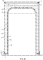
- the open end of the expandable bladder is expanded and placed over the barrel form as depicted in Figure 8A .
- the bladder is pulled down over the form so that the bladder open end is positioned proximate the form open end 33 and the bladder closed end is positioned proximate the form closed end 34, such as shown by example in Figure 8C .
- a top rim is positioned over the barrel form 31 so that the top rim encircles the form 31.
- a collapsible top rim with a living hinge is positioned over a collapsible heat stake plate with a living hinge.
- the bladder top drape 18 is positioned in the top rim channel 20 so that a portion of the top drape covers a portion of the inside surface of the top rim channel 20, such as shown by example in Figure 8C .
- an exterior barrel wall 2 can be positioned around the expandable bladder 3 covering the barrel form 31 so that a gap 32 is defined in between an inside surface 12 of the exterior barrel and the bladder exterior surface 17.
- the exterior barrel wall can be formed by flexing and welding a flexible sheet as described above before the exterior barrel wall is positioned around the interior barrel wall.
- the logos and/or graphics can be printed on the outside surface of the sheet prior to forming the sheet into the exterior barrel wall.
- the exterior wall top edge 13 is positioned in the top rim channel and in contact with a portion of the top drape of the expandable bladder which is also positioned in the top rim channel so as to form a friction fit seal between the top drape 18 and exterior wall top edge 13.
- an adhesive can be used to adhere the top drape of the bladder to the top rim channel and/or adhere the exterior wall top edge to the top drape of the expandable bladder.
- the distal end of the drain pipe can be positioned to extend through a hole defined in the exterior wall.
- a bottom rim can be positioned over the exterior wall bottom edge, such as shown by example in Figure 8C .
- the dimensions of the exterior barrel wall 2 and the interior barrel wall 3 can be configured so that the gap 32 defined in between the exterior wall inside surface 12 and the bladder exterior surface 17 can be about 1 inch to about 5 inches (about 2.5 cm to about 12.7 cm).
- insulative material is inserted into the gap through the bottom of the barrel to form the insulative layer 4.
- the insulative layer covers the bladder body segment.
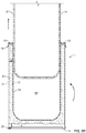
- the insulative layer covers the bladder exterior surface 35 at the closed end of the bladder as seen in Figure 8B .
- the barrel form can be removed to expose interior barrel cavity.
- the portable ice barrel is rotated from an upside-down position shown in Figure 8C into an upright position shown in Figure 8D before the barrel form is removed from the interior barrel cavity.
- the lid, sign holder, and sign extrusion can be secured to the top rim.
- casters can be secured to the underside of a barrel base and the portable ice barrel can be positioned onto the barrel base.
- the casters are secured to a collapsible barrel cooler bottom rim with a living hinge by a plurality of support tubes.
- FIGs 9-14E depict an embodiment of the portable ice barrel 101.
- the portable ice barrel 101 can include similar components as the example depicted in Figures 1-8 . These components are labeled with like reference numerals in the accompanying drawings but use 100 series reference numerals.
- a series of barrel height sections or baffles 104 instead of using insulative material 4, are used to provide insulation to the contents of the portable ice barrel 101.
- an outer and inner layer form a gap of air that provides insulation to the contents of the portable ice barrel 101.
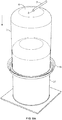
- Figure 9 shows a top perspective view of the example portable ice barrel 101
- Figure 10 shows a side perspective view.
- the exterior of the portable ice barrel 101 generally includes a top wall 135, a lid 124, a drain pipe 107, an exterior barrel wall 103, and a bottom rim 122 which can be configured to receive a series of wheels 137.
- the exterior barrel wall 103 can be formed as a graphic panel and can include any name, logo, or symbol depending on the contents and desired advertising.
- the top wall 135 has a partial rim 119 and can be configured to receive a lid 124.
- the lid 124 provides an opening into the interior barrel cavity 110 formed in the portable ice barrel 101, and can be hingedly connected to the top wall 135 by hinge 127.
- the lid 124 may also include a handle 128, which can be in the form of a projection for opening the lid 124.
- top wall 135 can be formed with a notch 128a for receiving the handle 128 of the lid 124.
- the lid 124 can be provided with a living hinge (not shown) that separates the lid 124 into two sections such that the lid 124 can be folded into a smaller configuration for easy and compact shipment.
- FIG 11 depicts an exploded perspective view of the portable ice barrel 101 showing both the exterior and interior components of the portable ice barrel 101.
- the portable ice barrel 10 includes an insulation layer 160 formed of barrel height sections 104, a bladder or liner 102, and a base assembly 136.
- the liner 103 forms an interior barrel cavity 110 for receiving contents, such as ice and any desired products.
- the barrel height sections 104 are configured to fit under the top wall 135 and between the exterior barrel wall and the liner 102.
- the barrel height sections 104 can each be formed identically.
- the barrel height sections 104 form the cylindrical insulation layer 160 by trapping air between the liner 102 and the exterior barrel wall 103.
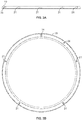
- each of the barrel height sections 104 can comprise 30 degrees of the cylinder forming the portable ice barrel 101.
- any number of sections can be provided for the desired insulation and manufacturability.
- the barrel height sections 104 are provided with a slight curvature such that they form a cylinder when assembled in the portable ice barrel 101. The curvature can be slight enough such that the barrel height sections 104 can be shipped in a mostly flat configuration.
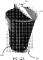
- FIGs 12A-12D depict perspective side and top views of the portable ice barrel 101 before attachment of the exterior barrier wall 103 onto the portable ice barrel 101.
- the outermost surfaces of the barrel height sections 104 are formed with a series of fins 142.
- the fins 142 extend from an outermost wall forming the barrel height sections 104 to the exterior barrier wall 103.
- the fins 142 are configured to trap air between the exterior barrier wall 103 and the liner 102. Air is generally a good thermal insulator, and helps to slow outside or ambient temperatures from melting the ice or warming the contents stored in the interior barrel cavity 110. Alternatively, the fins 142 trap air to help prevent heat from escaping the interior barrel cavity 110 should it be desired to store warm contents. In this way, the barrel height sections 104 provide thermal insulation to the liner 102 and the contents stored therein.
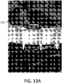
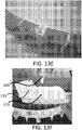
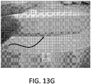
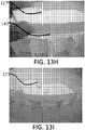
- FIGS 13A-13F show partially formed barrel sections 104 to illustrate an example connection method for securing the barrel sections 104 together.
- the barrel sections 104 can be provided with tongue and groove type connections 148.
- each side of the barrel sections 104 can be provided with either a tongue 149 or a groove 150.
- the tongue 149 can be formed of two L-shaped legs 151 that project outwardly.
- the L-shaped legs 151 of the tongue 149 can be formed of a thin plastic material such that the legs have a degree of resiliency.
- the groove can be defined by two facing L-shaped legs 152 and a resilient V-shaped projection 153.
- the legs 151 can be configured to resiliently extend into the groove 150 such that when the legs 151 of the tongue 149 are placed into contact with the groove 150, the L-shaped legs 151 contact the L-shaped legs 152 causing the L-shaped legs 151 to resiliently bias against the L-shaped legs 152.
- the tongue 149 is aligned with the groove 150 such that the legs 151 extend into the groove 150.
- the barrel sections 104 are held together securely in both a vertical and horizontal direction. It is contemplated that the barrel sections 104 can be secured together using any known connection method such as removable fasteners, adhesives, snap-fit, etc.
- the L-shaped legs 151, the L-shaped legs 152, and the V-shaped projection 153 also define a recess for receiving a push-in clip 146 located on a top wall section to secure the top wall 135 to the top of the barrel sections 104.
- the push-in clip 146 can be a Christmas tree-type clip.
- the clips 146 are installed through a hole 158 in the top wall 135.
- the clips 146 can be provided with resilient ribs, which extend along the length of the shaft of the clips 146.
- the ribs located on the shaft of the clips 146 maintain the top wall 135 on the barrel sections 104.
- the clip 146 can be designed as a one way, press fit application such that once installed, the clips 146 are extremely difficult to remove to secure the top wall 135 to the insulation layer 160.
- the clips 146 can be configured to require no turning of a screw or fastener, which reduces the amount of labor to assemble the portable ice barrel.
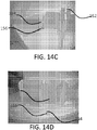
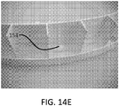
- Figures 14A-14E illustrate partially formed bottom sections of the barrel sections 104 to illustrate a method of connecting the bottom rim 122 to the barrel sections 104.
- the bottom rim 122 can be provided with a resilient locking tab 154 for securing the bottom rim 122 to the barrel sections 104 without the use of tools.
- the bottom rim 122 can be provided with an opening 156, which provides a cutout for the locking tab 154 to flex.
- the barrel sections 104 can be provided with a corresponding opening 157 for receiving the locking tab 154.
- the locking tab 154 flexes within the opening 156 and into the corresponding opening 157 to secure the bottom rim 122 to the barrel sections 104.
- the locking tab 154 can be provided with a ramp 154A, which permits the locking tab to move outwardly when the bottom rim 122 is placed into contact with the barrel sections 144A-144F. Once the locking tab 154 is aligned with the opening 157 the resiliency of the tab moves the ramp 154A inwardly into the opening 157 to secure the bottom rim 122 to the barrel sections 104.
- the liner 102 can be formed of a similar liner material as the example shown in Figures 1-8 . Additionally, as shown in Figures 11 , 15 , and 13A , a series of clips 140 can be used to support the liner 102 inside the portable ice barrel 101. In particular, the liner 102 can be held in place onto the insulation layer 160 by a series of clips 140. The clips 140 can be formed U-shaped such that the clips 140 can extend over the rim of the insulation layer 160 and the liner 102 to securely hold the liner 102 into place in the portable ice barrel 101.
- the top wall 135 can be formed of sections. As shown in Figures 13G and 13E , the sections can make up the hinge 127 for receiving the lid 124. Although not shown, the sections can also form the partial rim 119, and can be secured to the sections forming the hinge 127 using any known method. As discussed above, the top wall 135 can be secured to the barrel sections 104 using a push-in clip 146.
- the base assembly 136 can be formed of a support disc 138, a series of supports 139A-139D to form a grid 139, the bottom rim 122, and wheels 137.
- the bottom rim 122 can be formed with a wheel mount or projection 162 for receiving the wheels 137.
- the supports 139A-D and grid 139 form an inexpensive, transportable, and robust foundation structure.
- each support 139A-139D can be provided with a series of slits 143 for receiving a respective slit 143 on a corresponding support grid 139. Therefore, the grid 139 can be assembled quickly by aligning the slits 143 on the supports 139A-D.
- the grid 139 can be provided with two or more supports depending on the size and desired strength of the base assembly.
- the supports 139A-139D can be formed of any known and suitable material and in one example can be formed of a plastic material, cardboard, or other like material.
- the base assembly can be formed by a single collapsible bottom rim that incorporates a living hinge. The casters are secured to a collapsible barrel bottom rim by a plurality of support tubes.
- the drain pipe 107 can be formed similar to drain pipe 7 and extends from an interior of the portable ice barrel 101 to the exterior to provide for an outlet for ice water.
- the drain pipe 107 can be built into the liner 102.
- one of the barrel height sections 104 can be provided with a die cut hole for receiving the drain pipe 107 therethrough.
- the barrel sections 104 can be connected to one another using the tongue and groove connection as described above.
- the base 136 can then be assembled by forming the supports 139A-139D into a grid 139.
- the disc 138 and the support grid 139 can then be placed inside the insulation layer 160 formed by the barrel sections 140.
- the disc 138 and the support grid 139 can then be held in the barrel sections 140 by securing the base rim 122 to the barrel sections 104.
- the wheels 137 can then be placed on the base rim 122, and can be held into place on the base rim 122 via a snap fit.
- the base rim 122 can be secured to the barrel sections 104 by aligning the tabs 154 with the holes 157.
- the liner 102 can be pulled or stretched over the insulation layer and held into place by the clips 140.
- the top wall 135 and partial top rim 119 can then be assembled, and the lid 124 can be secured to the top wall 135.
- the top wall 135 can be secured to the top of the barrel sections 104 by the clips 146.
- the top wall 135 and top rim 119 also secure the liner 102 by a press fit between the top rim 119 and the barrel sections 104.
- the exterior barrel wall 103 can be printed and then placed around and secured to the barrel sections 104.
- a portable ice barrel can include an exterior barrel wall, an interior barrel wall, and insulative layer positioned in between the exterior barrel wall and the interior barrel wall.
- the interior barrel wall can comprise an expandable bladder made of flexible material and the expandable bladder can have an open end, a closed end, and can be adapted to expand from a collapsed position into an expanded position. In the expanded position, the expandable bladder can be configured to define an interior barrel cavity, the closed end can be configured to contain ice within the barrel cavity, and the open end can allow access to the barrel cavity.
- the exterior barrel wall can comprise a flexible sheet made of a semi-rigid material and the insulative material can comprise of a rigid expanded polystyrene foam material. The insulative material can be configured to provide structural support for the interior barrel wall.
- the expandable bladder can include a drain pipe having a drain pipe proximal end and a drain pipe distal end.
- the drain pipe proximal end can be secured to the closed end of the expandable bladder.
- the drain pipe can be configured such that the drain pipe distal end extends through the exterior barrel wall.
- a top rim can be positioned over the barrel form so that the top rim encircles the form open end, and the top rim includes a top rim channel defined within the top rim.
- the expandable bladder can include a top drape extending from a perimeter of the open end of the expandable bladder.
- the top drape extending from a perimeter of the open end of the expandable bladder can be positioned in the top rim channel so that the top drape covers an inner surface of the channel.
- a top edge of the exterior barrel wall can be positioned in the top rim channel and on top of the top drape.
- the top drape of the expandable bladder can be secured proximate the top sheet edge of the exterior wall and at least a portion of the top drape of the expandable bladder can be draped over the top sheet edge of the exterior wall.
- the top rim can be secured to the top sheet edge of the exterior wall so that the portion of the top drape of the expandable bladder and a portion of the top edge of the exterior wall are positioned within the top rim channel.
- the exterior barrel wall can be cylindrical and include an exterior wall outside surface, an exterior wall inside surface, an exterior wall top edge, and an exterior wall bottom edge.
- the expandable bladder includes a body segment extending between the open end and the closed end.
- the body segment of the expandable bladder can be cylindrical.
- the expandable bladder can also include a bladder interior surface and bladder exterior surface.
- the inner diameter of the body segment can be between about 18 inches to about 24 inches (about 46 cm to about 61 cm) when the expandable bladder is in the expanded position and a diameter of the exterior barrel wall can be about 1 inch to about 5 inches (about 2.5 cm to about 12.7 cm) greater than the diameter of the body segment.
- Figures 15A-15F depict another example portable ice barrel 201, which is not part of the claimed invention, where like reference numerals refer to the same or similar elements in all of the various views but include 200 series reference numerals.
- the example shown in Figures 15A-15F is similar to the example shown in Figures 9-14E , however this example implements an optional exterior liner 204 instead of barrel height sections.
- the example shown in Figures 15A-15F also has a different base assembly 235, but the base disclosed in relation to the example discussed in relation to Figures 9-14E can optionally be used in conjunction with this example.
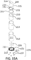
- FIG 15A shows an exploded view of the example portable ice barrel 201.
- the example portable ice barrel 201 can include lid 224 which can incorporate living hinges 215 to allow the lid to be folded for compact shipment or storage.
- an insulation layer may be formed by trapping air between the interior liner 202 and the exterior barrel wall 203.
- the liner 202 forms an interior barrel cavity 210 for receiving contents, such as ice and any desired products.
- the interior liner 202 can be configured to be collapsible such that it can be packed efficiently during shipment.
- Fasteners, hole plugs, or clips 240 can be included to secure the top rim 235 to the interior liner 202 and an optional collapsible heat stake plate 206.
- the top rim 235 may incorporate living hinges 215 to provide for collapsibility, and fits over the optional heat stake plate 206, interior bladder or liner 202, optional exterior liner 204, and exterior wall 203.
- the optional exterior liner 204 can be formed of a single sheet of material that can be rolled into a smaller shape for packing efficiently.
- the exterior wall 203 can be formed of a 0.09 inch (0.23 cm) thick styrene sheet that can be formed into a cylinder.
- the styrene sheet can formed be with a channel extending along one of the edges such that the other edge can be placed into the channel to form the exterior wall into a cylinder.
- the exterior wall 203 can also be rolled into a smaller shape for efficient packaging.
- a graphic label can be included on the exterior wall 203 of the portable barrel 201.
- a base 236 can be formed of a bottom rim 222, casters 237, and support tubes 208.
- the bottom rim 222 can include a living hinge 215 that allows the bottom rim 222 to be folded into a collapsed position.
- the casters 237 are configured to attach to the bottom rim 222 via an interference or snap fit connection to allow for an easy assembly.
- the support tubes 208 are configured to fit onto a series of projections 219 located on the bottom rim 222.
- the base discussed above in relation to the example in Figures 9-14E can be used in conjunction with the example shown in Figures 15A-15F .
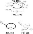
- FIG 15B1 depicts a top view of the collapsible top rim 235 and Fig. 15B2 depicts a side view of the collapsible top rim 235.
- the top rim 235 can include a living hinge 215 and multiple slots or holes 241.
- the slots or holes 241 facilitate securing the top rim 235 to the heat stake plate 206, the top of the inner liner 202, the top of the outer liner 204, and the exterior wall 203.
- Figure 15C depicts a top view perspective of the heat stake plate 206.
- Heat stake plate 216 is composed of multiple heat stake plate sections 216 as depicted in Figure 15D . Heat stake plate sections 216 include slots or holes 217 to accommodate various types of fasteners.
- bottom rim 222 and bottom rim 222 may include a bottom rim channel defined in the bottom of the rim that attaches by tongue and groove to the bottom edge of the exterior wall 203 which can include a tongue and groove type fitting that secures to the bottom rim 122 or optionally bottom rim 222.
- Bottom rim 122 and bottom rim 222 may include living hinges 215 to allow the structure to be folded to decrease shipping volume.
- Figure 15E depicts a top view of the bottom rim 222.
- Collapsible bottom rim 222 incorporates a living hinge 215 and slots or holes 241 for receiving a series of suitable fasteners.
- the bottom rim 222 is secured via fasteners to the bottom of inner liner 202, outer liner 204, and exterior wall 203 through the various slots or holes 241.
- Figure 15F depicts the bottom rim 222.
- the bottom rim can be provided with support tube projections 218.
- the support tubes 208 can be place over the support tube projections 218.
- Figure 16 shows an example container that can be used to ship or store the portable cooler examples discussed herein.
- the portable cooler examples discussed here can be configured to be easily collapsible to fit in a much smaller sized container than traditional ice barrels.
- the container can define a length, a height, and a width.
- the width of the container can be less than a diameter of the assembled portable ice barrel.
- the ratio of the width of the container to the diameter of the assembled portable ice barrel can range from 1 to 5 to 1 to 3.
- the ratio of the width of the container to the diameter of the assembled portable ice barrel can range from 1 to 10 to 1 to 2.
- the height is greater than the length
- the length is greater than the width.
- the components of the portable ice barrel can be shipped in a container having a predominately flat configuration such that the portable ice barrel can be shipped and assembled at the receiving end.
- the portable ice barrel can be packaged in a 34" by 24" by 12" box (86.4 cm x 61 cm x 30.5) cm having volumetric capacity of 9792 cubic inches (160462 cubic cm).
- the portable ice barrel can be packaged in a 32" by 24" by 8" (86.4 cm by 61 cm x 20.3 cm) box having volumetric capacity of 6144 cubic inches (100682 cubic cm).
- the portable ice barrel can be packaged in a 34" by 14" by 8" (86.4 cm by 35.6 cm by 20.3 cm) box having volumetric capacity of 3808 cubic inches (62402 cubic cm).
- the volumetric capacity of the inner liner of the cooler can be 6295 cubic inches (103157 cubic cm) for storing the desired contents.
- a ratio of the volumetric storage capacity of the inner liner of the portable cooler to the volume of the container can be between 1.5:1 to 4:1.
- the individual components can be shipped separately in individualized containers.
- the individual components can then be reassembled at the final destination or combined with other units to form complete kits and sold at retail outlets.
- a method of assembling a portable ice barrel can include positioning an expandable bladder over a barrel form such that a bladder inner surface covers a form exterior surface.
- the bladder open end can be positioned proximate a form open end and a bladder closed end can be positioned proximate a form closed end.
- the expandable bladder can comprise of flexible material such that the expandable bladder is adapted to expand from a collapsed position into an expanded position.
- An exterior barrel wall can be positioned around the expandable bladder and covering the barrel form such that a gap is defined in between an inside surface of the exterior barrel wall and a bladder exterior surface. Insulative material can be inserted in the gap between the inside surface of the exterior barrel wall and the bladder exterior surface.
- the expandable bladder can be separated from the barrel form such that the expandable bladder is configured to define an interior barrel cavity and the closed end is configured to contain ice within the barrel cavity and the open end is configured to allow access to the barrel cavity.
- Inserting insulative material can include injecting expandable polystyrene foam material in the gap such that the expanded polystyrene foam material is configured to provide structural support for the interior barrel wall.
- a top rim can be positioned over the barrel form so that the top rim encircles the form open end, and the top rim includes a top rim channel defined within the top rim.
- a top drape extending from a perimeter of the open end of the expandable bladder can be positioned in the top rim channel so that the top drape covers an inner surface of the channel.
- a top edge of the exterior barrel wall can be positioned in the top rim channel and on top of the top drape.
- the example portable ice barrels of the instant disclosure can provide for optimized shipping, use, and assembly of the portable ice barrel according to methods disclosed herein.
- components of the portable ice barrel are shipped to an assembly location located in the vicinity of the point of use.
- a kit which includes the expandable bladder in the collapsed position is shipped to an assembly location.
- the kit includes the expandable bladder in the collapsed position, the top rim, the bottom rim, the lid, the barrel base, and casters.
- the assembly location includes flexible sheets with which to form the exterior barrel wall as described above.
- the assembly location includes facilities to print graphics on the outside surface of the sheet as described above.
- the assembly location can include the insulative material.
- the assembly location includes a machine and material for injecting polystyrene foam during assembly of the portable ice barrel as described above.
- the barrel form, flexible sheets, insulative material, and/or machine for injecting insulative material can be shipped to the assembly location.
- a base of the portable ice barrel can include a grid formed by a series of supports, a disc, a rim, and a series of wheels.
- a top wall of the portable ice barrel can have an opening and a lid configured to cover the opening.
- the lid can also include a handle and an exterior barrel wall.
- the plurality of sections, the base, the top wall, the inner liner, and the exterior barrel wall can be configured to be assembled into a portable ice barrel.
- the plurality of sections, the base, the top wall, the inner liner, and the exterior barrel wall can be configured to be detached from one another and shipped in a container having flat configuration.
- a plurality of clips can hold the inner liner onto the cylindrical insulation layer, and the top wall can be secured to the cylindrical insulation layer by a series of clips.
- the plurality of sections can include a series of fins which can be configured to trap air to provide thermal insulation.
- conventional ice barrels are often shipped fully assembled to the point of use from a distant location. This results in wasted resources from shipping air in the interior cavity of the barrel. For example, often times, the cost of shipping the fully assembled conventional barrel is greater than the cost of the barrel itself.
- conventional ice barrels include injection molded interior walls which add to the weight of the barrel as compared to the portable barrel with expandable bladder disclosed herein.
- the reduced weight of the portable ice barrel disclosed herein provides efficiencies, for example, in shipping costs and ease of use. Users of conventional barrels often turn the barrel over to empty water from the interior cavity, which can lead to injury due to the weight of the barrel.
- the reduced weight of the portable barrel of the instant disclosure can, for example, reduce instances of injury from turning the barrel over.
Landscapes
- Engineering & Computer Science (AREA)
- Mechanical Engineering (AREA)
- Physics & Mathematics (AREA)
- Thermal Sciences (AREA)
- General Engineering & Computer Science (AREA)
- Chemical & Material Sciences (AREA)
- Combustion & Propulsion (AREA)
- Packages (AREA)
Claims (10)
- Tragbares Eisfass (101), aufweisend:eine Basis (136) mit einem unteren Rand (122);eine obere Wand (135) mit einem oberen Rand (119) und einer Öffnung;eine zylindrische Isolierschicht (160) mit einer Öffnung;eine Innenauskleidung (102), die sich in die Öffnung der oberen Wand (135) und in die Öffnung der zylindrischen Isolierschicht (160) erstreckt, um einen inneren Hohlraum (110) des Fasses zu bilden;wobei die zylindrische Isolierschicht (160) aus einer Mehrzahl von mit einem Krümmungsgrad versehenen Abschnitten (104) gebildet ist, wobei die Mehrzahl von Abschnitten (104) zum Bilden einer thermischen Isolierung eine Reihe von lufteinschließenden Rippen (142) aufweist; undeine äußere Fasswand (103);wobei die Basis (136), die obere Wand (135), die Innenauskleidung (102), die zylindrische Isolierschicht (160) und die äußere Fasswand (103) so ausgebildet sind, dass sie zu dem tragbaren Eisfass (101) zusammengebaut werden können; unddie Basis (136), die obere Wand (135), die Innenauskleidung (102), die zylindrische Isolierschicht (160) und die äußere Fasswand (103) zum Versenden in einem Behälter flacher Bauart auseinandergenommen werden können, wobei der Behälter eine Länge, Höhe und Breite so definiert, dass die Breite des Behälters kleiner ist als ein Durchmesser des zusammengebauten tragbaren Eisfasses (101).
- Tragbares Eisfass (101) nach Anspruch 1, wobei die Basis (136) ferner ein Gitter (139), eine Scheibe (138) und eine Reihe von Rädern (137) aufweist.
- Tragbares Eisfass (101) nach Anspruch 1, ferner aufweisend eine Mehrzahl von Klammern (140) zum Halten der Innenauskleidung (102) auf der zylindrischen Isolierschicht (160).
- Tragbares Eisfass (101) nach Anspruch 1, bei dem die obere Wand (135) an der zylindrischen Isolierschicht (160) durch eine Reihe von Klammern (146) befestigt ist.
- Tragbares Eisfass (101) nach Anspruch 1, welches ferner ein Ablaufrohr (107) aufweist.
- Bausatz für ein tragbares Eisfass, aufweisend:eine Basis (136) mit einem unteren Rand (122);eine obere Wand (135) mit einem oberen Rand (119) und einer Öffnung;eine Innenauskleidung (102);eine zylindrische Isolierschicht (160) mit einer Öffnung; undeine äußere Fasswand (103); wobeidie Basis (136), der obere Rand (119), die obere Wand (135), die Innenauskleidung (102), die zylindrische Isolierschicht (160) und die äußere Fasswand (103) zu einem tragbaren Eisfass (101) zusammensetzbar sind, in dem sich die Innenauskleidung (102) in die Öffnung der oberen Wand (135) und in die Öffnung der zylindrischen Isolierschicht (160) erstreckt, um einen inneren Hohlraum (110) des Fasses zu bilden, welcher eine volumetrische Speicherkapazität definiert, und in dem sich die zylindrische Isolierschicht (160) zwischen der Innenauskleidung (102) und der äußeren Fasswand (103) befindet;ferner aufweisend eine Mehrzahl von Abschnitten (104), die zusammengesetzt werden können, um die zylindrische Isolierschicht (160) zu bilden, wobei die Mehrzahl an Abschnitten (104) zum Bilden einer thermischen Isolierung eine Reihe von lufteinschließenden Rippen (142) aufweist; undeinen Behälter flacher Bauart, wobei der Behälter eine Länge, eine Höhe und eine Breite definiert;wobei die Basis (136), die obere Wand (135), die Innenauskleidung (102), die zylindrische Isolierschicht (160) und die äußere Fasswand (103) so ausgebildet sind, dass sie zum Versenden in dem Behälter auseinandergenommen werden können; undwobei das Volumen des Behälters kleiner ist als die volumetrische Speicherkapazität des zusammengebauten tragbaren Eisfasses (101).
- Bausatz für ein tragbares Eisfass nach Anspruch 6, wobei die Basis (136) ferner eine Mehrzahl von Abschnitten (104) aufweist, die so ausgebildet sind, dass sie ein Gitter (139) bilden, eine Scheibe (138) und eine Reihe von Rädern (137).
- Bausatz für ein tragbares Eisfass nach Anspruch 6, ferner aufweisend eine Mehrzahl von Abschnitten (104) die unter der oberen Wand (135) und zwischen der äußeren Fasswand (103) und der Innenauskleidung (102) eingepasst werden können.
- Bausatz für ein tragbares Eisfass nach Anspruch 6, wobei die Abschnitte (104) eine leichte Krümmung aufweisen.
- Bausatz für ein tragbares Eisfass nach Anspruch 6, wobei die Abschnitte (104) eine Nut- und Federverbindung aufweisen.
Applications Claiming Priority (3)
| Application Number | Priority Date | Filing Date | Title |
|---|---|---|---|
| US201361900925P | 2013-11-06 | 2013-11-06 | |
| US201462017728P | 2014-06-26 | 2014-06-26 | |
| PCT/US2014/064400 WO2015069931A1 (en) | 2013-11-06 | 2014-11-06 | Portable ice barrel |
Publications (2)
| Publication Number | Publication Date |
|---|---|
| EP3066403A1 EP3066403A1 (de) | 2016-09-14 |
| EP3066403B1 true EP3066403B1 (de) | 2021-04-28 |
Family
ID=52001075
Family Applications (1)
| Application Number | Title | Priority Date | Filing Date |
|---|---|---|---|
| EP14805728.4A Active EP3066403B1 (de) | 2013-11-06 | 2014-11-06 | Tragbares eisfass |
Country Status (6)
| Country | Link |
|---|---|
| US (1) | US9310117B2 (de) |
| EP (1) | EP3066403B1 (de) |
| KR (1) | KR101836449B1 (de) |
| CN (1) | CN106068430B (de) |
| AU (1) | AU2014346657B2 (de) |
| WO (1) | WO2015069931A1 (de) |
Families Citing this family (9)
| Publication number | Priority date | Publication date | Assignee | Title |
|---|---|---|---|---|
| US9777955B2 (en) | 2013-11-06 | 2017-10-03 | Rtc Industries, Inc. | Collapsible insulating device |
| EP3390930B1 (de) * | 2015-12-15 | 2021-04-28 | RTC Industries, Inc. | Zusammenklappbare isoliervorrichtung |
| KR102189183B1 (ko) * | 2016-04-11 | 2020-12-09 | 알티씨 인더스트리즈, 인크. | 접이식 단열 장치 |
| AT520285B1 (de) | 2017-09-19 | 2019-03-15 | Single Use Support Gmbh | Verfahren zum Einfrieren einer Flüssigkeit |
| US20200172321A1 (en) * | 2018-11-30 | 2020-06-04 | Lightbulb Innovation, LLC | Removable Lining System For Coolers |
| US12503294B2 (en) | 2022-07-19 | 2025-12-23 | Yeti Coolers, Llc | Container and method of forming a container |
| USD1114446S1 (en) | 2022-07-19 | 2026-02-17 | Yeti Coolers, Llc | Container |
| CN115258422B (zh) * | 2022-09-20 | 2022-12-20 | 成都易速物流有限公司 | 一种基于保温隔热循环管路系统的隔热桶 |
| CN116675172B (zh) * | 2023-06-28 | 2024-01-26 | 国网青海省电力公司海北供电公司 | 一种便携式加油装置 |
Citations (2)
| Publication number | Priority date | Publication date | Assignee | Title |
|---|---|---|---|---|
| US4850506A (en) * | 1986-12-17 | 1989-07-25 | Connelly Containers, Inc. | Container for fluent material |
| US20100012550A1 (en) * | 2008-07-17 | 2010-01-21 | Franklin Dedmon | Bag-in-bag container for bulk handling of fluids |
Family Cites Families (16)
| Publication number | Priority date | Publication date | Assignee | Title |
|---|---|---|---|---|
| NL83368C (de) | 1900-01-01 | |||
| US2178778A (en) * | 1938-05-03 | 1939-11-07 | Hugh F Curry | Container and seam closure therefor |
| US2866251A (en) * | 1956-07-05 | 1958-12-30 | Ford Meter Box Company Inc | Single use mold for obround water meter barrels |
| US3347060A (en) * | 1965-12-22 | 1967-10-17 | Bernard R Barkan | Collapsible, portable freezer box |
| US4514993A (en) | 1984-03-02 | 1985-05-07 | Idttkow, Inc. | Insulated barrel cooler |
| TW207982B (en) * | 1992-04-17 | 1993-06-21 | Brainpower Inc | System for confining articles in a container |
| US5456357A (en) * | 1994-07-07 | 1995-10-10 | Wenner; John W. | Nestable bucket and carrier |
| WO2002085749A1 (en) | 2001-04-20 | 2002-10-31 | Courier Cool Ltd | Collapsible transport container |
| GB0217331D0 (en) * | 2002-07-26 | 2002-09-04 | Clinimed Holdings Ltd | Thermally insulative containers |
| US20070145051A1 (en) * | 2005-12-22 | 2007-06-28 | Michael Uffner | Mobile cooler station |
| CN201108282Y (zh) * | 2007-10-24 | 2008-09-03 | 郑胜棉 | 一种旅行保温冰桶 |
| US20100011798A1 (en) * | 2008-07-18 | 2010-01-21 | Display Industries, Llc. | Cooler with automatic product height adjustment mechanism |
| US8430265B2 (en) * | 2008-12-11 | 2013-04-30 | M & C Innovations, Llc | Collapsible coolers |
| US8209995B2 (en) * | 2009-04-23 | 2012-07-03 | Packit, Llc | Collapsible insulated container |
| WO2011150414A1 (en) | 2010-05-28 | 2011-12-01 | Display Technologies | Knock down barrel and methods for assembly |
| US9733007B2 (en) * | 2013-03-15 | 2017-08-15 | Beergo, Inc. | Liquid vessel cooling system |
-
2014
- 2014-11-06 KR KR1020167015092A patent/KR101836449B1/ko not_active Expired - Fee Related
- 2014-11-06 CN CN201480070337.8A patent/CN106068430B/zh not_active Expired - Fee Related
- 2014-11-06 EP EP14805728.4A patent/EP3066403B1/de active Active
- 2014-11-06 AU AU2014346657A patent/AU2014346657B2/en not_active Ceased
- 2014-11-06 US US14/535,137 patent/US9310117B2/en not_active Expired - Fee Related
- 2014-11-06 WO PCT/US2014/064400 patent/WO2015069931A1/en not_active Ceased
Patent Citations (2)
| Publication number | Priority date | Publication date | Assignee | Title |
|---|---|---|---|---|
| US4850506A (en) * | 1986-12-17 | 1989-07-25 | Connelly Containers, Inc. | Container for fluent material |
| US20100012550A1 (en) * | 2008-07-17 | 2010-01-21 | Franklin Dedmon | Bag-in-bag container for bulk handling of fluids |
Also Published As
| Publication number | Publication date |
|---|---|
| WO2015069931A1 (en) | 2015-05-14 |
| US20150122826A1 (en) | 2015-05-07 |
| KR20160083931A (ko) | 2016-07-12 |
| US9310117B2 (en) | 2016-04-12 |
| KR101836449B1 (ko) | 2018-03-09 |
| AU2014346657A1 (en) | 2016-05-26 |
| EP3066403A1 (de) | 2016-09-14 |
| CN106068430A (zh) | 2016-11-02 |
| CN106068430B (zh) | 2020-04-03 |
| AU2014346657B2 (en) | 2017-03-23 |
Similar Documents
| Publication | Publication Date | Title |
|---|---|---|
| AU2014346657B2 (en) | Portable ice barrel | |
| US11667455B2 (en) | Configurable container | |
| EP3390930B1 (de) | Zusammenklappbare isoliervorrichtung | |
| US20210180849A1 (en) | Collapsible Insulating Device | |
| US7874177B2 (en) | Pouch for carrying temperature-sensitive products | |
| US6244439B1 (en) | Portable doll carousel | |
| US20150076144A1 (en) | Foldable sealing container apparatus | |
| US20140339227A1 (en) | Foldable sealing container apparatus | |
| EP3443281B1 (de) | Zusammenklappbare isoliervorrichtung | |
| JPH0520662Y2 (de) | ||
| JP2004528240A (ja) | 折りたたみ可能な輸送コンテナ | |
| US11584582B2 (en) | Convertible beverage container package having an integrated cooler compartment | |
| JPH02139339A (ja) | 組立式気密容器セツト | |
| AU2006200630A1 (en) | Partitioning for Shopping Bag |
Legal Events
| Date | Code | Title | Description |
|---|---|---|---|
| PUAI | Public reference made under article 153(3) epc to a published international application that has entered the european phase |
Free format text: ORIGINAL CODE: 0009012 |
|
| 17P | Request for examination filed |
Effective date: 20160524 |
|
| AK | Designated contracting states |
Kind code of ref document: A1 Designated state(s): AL AT BE BG CH CY CZ DE DK EE ES FI FR GB GR HR HU IE IS IT LI LT LU LV MC MK MT NL NO PL PT RO RS SE SI SK SM TR |
|
| AX | Request for extension of the european patent |
Extension state: BA ME |
|
| DAX | Request for extension of the european patent (deleted) | ||
| STAA | Information on the status of an ep patent application or granted ep patent |
Free format text: STATUS: EXAMINATION IS IN PROGRESS |
|
| 17Q | First examination report despatched |
Effective date: 20190703 |
|
| RIC1 | Information provided on ipc code assigned before grant |
Ipc: B65D 6/24 20060101ALI20201001BHEP Ipc: F25D 3/06 20060101AFI20201001BHEP Ipc: B65D 81/38 20060101ALI20201001BHEP |
|
| GRAP | Despatch of communication of intention to grant a patent |
Free format text: ORIGINAL CODE: EPIDOSNIGR1 |
|
| STAA | Information on the status of an ep patent application or granted ep patent |
Free format text: STATUS: GRANT OF PATENT IS INTENDED |
|
| INTG | Intention to grant announced |
Effective date: 20201110 |
|
| RIN1 | Information on inventor provided before grant (corrected) |
Inventor name: SCHLESSINGER, GIDEON Inventor name: GEIGER, FRED Inventor name: LOZANO, JULIO |
|
| GRAS | Grant fee paid |
Free format text: ORIGINAL CODE: EPIDOSNIGR3 |
|
| GRAA | (expected) grant |
Free format text: ORIGINAL CODE: 0009210 |
|
| STAA | Information on the status of an ep patent application or granted ep patent |
Free format text: STATUS: THE PATENT HAS BEEN GRANTED |
|
| AK | Designated contracting states |
Kind code of ref document: B1 Designated state(s): AL AT BE BG CH CY CZ DE DK EE ES FI FR GB GR HR HU IE IS IT LI LT LU LV MC MK MT NL NO PL PT RO RS SE SI SK SM TR |
|
| REG | Reference to a national code |
Ref country code: GB Ref legal event code: FG4D |
|
| REG | Reference to a national code |
Ref country code: CH Ref legal event code: EP |
|
| REG | Reference to a national code |
Ref country code: AT Ref legal event code: REF Ref document number: 1387507 Country of ref document: AT Kind code of ref document: T Effective date: 20210515 |
|
| REG | Reference to a national code |
Ref country code: DE Ref legal event code: R096 Ref document number: 602014077029 Country of ref document: DE |
|
| REG | Reference to a national code |
Ref country code: IE Ref legal event code: FG4D |
|
| REG | Reference to a national code |
Ref country code: LT Ref legal event code: MG9D |
|
| REG | Reference to a national code |
Ref country code: AT Ref legal event code: MK05 Ref document number: 1387507 Country of ref document: AT Kind code of ref document: T Effective date: 20210428 |
|
| PG25 | Lapsed in a contracting state [announced via postgrant information from national office to epo] |
Ref country code: HR Free format text: LAPSE BECAUSE OF FAILURE TO SUBMIT A TRANSLATION OF THE DESCRIPTION OR TO PAY THE FEE WITHIN THE PRESCRIBED TIME-LIMIT Effective date: 20210428 Ref country code: LT Free format text: LAPSE BECAUSE OF FAILURE TO SUBMIT A TRANSLATION OF THE DESCRIPTION OR TO PAY THE FEE WITHIN THE PRESCRIBED TIME-LIMIT Effective date: 20210428 Ref country code: NL Free format text: LAPSE BECAUSE OF FAILURE TO SUBMIT A TRANSLATION OF THE DESCRIPTION OR TO PAY THE FEE WITHIN THE PRESCRIBED TIME-LIMIT Effective date: 20210428 Ref country code: FI Free format text: LAPSE BECAUSE OF FAILURE TO SUBMIT A TRANSLATION OF THE DESCRIPTION OR TO PAY THE FEE WITHIN THE PRESCRIBED TIME-LIMIT Effective date: 20210428 Ref country code: BG Free format text: LAPSE BECAUSE OF FAILURE TO SUBMIT A TRANSLATION OF THE DESCRIPTION OR TO PAY THE FEE WITHIN THE PRESCRIBED TIME-LIMIT Effective date: 20210728 Ref country code: AT Free format text: LAPSE BECAUSE OF FAILURE TO SUBMIT A TRANSLATION OF THE DESCRIPTION OR TO PAY THE FEE WITHIN THE PRESCRIBED TIME-LIMIT Effective date: 20210428 |
|
| PG25 | Lapsed in a contracting state [announced via postgrant information from national office to epo] |
Ref country code: GR Free format text: LAPSE BECAUSE OF FAILURE TO SUBMIT A TRANSLATION OF THE DESCRIPTION OR TO PAY THE FEE WITHIN THE PRESCRIBED TIME-LIMIT Effective date: 20210729 Ref country code: LV Free format text: LAPSE BECAUSE OF FAILURE TO SUBMIT A TRANSLATION OF THE DESCRIPTION OR TO PAY THE FEE WITHIN THE PRESCRIBED TIME-LIMIT Effective date: 20210428 Ref country code: IS Free format text: LAPSE BECAUSE OF FAILURE TO SUBMIT A TRANSLATION OF THE DESCRIPTION OR TO PAY THE FEE WITHIN THE PRESCRIBED TIME-LIMIT Effective date: 20210828 Ref country code: PL Free format text: LAPSE BECAUSE OF FAILURE TO SUBMIT A TRANSLATION OF THE DESCRIPTION OR TO PAY THE FEE WITHIN THE PRESCRIBED TIME-LIMIT Effective date: 20210428 Ref country code: NO Free format text: LAPSE BECAUSE OF FAILURE TO SUBMIT A TRANSLATION OF THE DESCRIPTION OR TO PAY THE FEE WITHIN THE PRESCRIBED TIME-LIMIT Effective date: 20210728 Ref country code: PT Free format text: LAPSE BECAUSE OF FAILURE TO SUBMIT A TRANSLATION OF THE DESCRIPTION OR TO PAY THE FEE WITHIN THE PRESCRIBED TIME-LIMIT Effective date: 20210830 Ref country code: ES Free format text: LAPSE BECAUSE OF FAILURE TO SUBMIT A TRANSLATION OF THE DESCRIPTION OR TO PAY THE FEE WITHIN THE PRESCRIBED TIME-LIMIT Effective date: 20210428 Ref country code: SE Free format text: LAPSE BECAUSE OF FAILURE TO SUBMIT A TRANSLATION OF THE DESCRIPTION OR TO PAY THE FEE WITHIN THE PRESCRIBED TIME-LIMIT Effective date: 20210428 Ref country code: RS Free format text: LAPSE BECAUSE OF FAILURE TO SUBMIT A TRANSLATION OF THE DESCRIPTION OR TO PAY THE FEE WITHIN THE PRESCRIBED TIME-LIMIT Effective date: 20210428 |
|
| REG | Reference to a national code |
Ref country code: NL Ref legal event code: MP Effective date: 20210428 |
|
| PG25 | Lapsed in a contracting state [announced via postgrant information from national office to epo] |
Ref country code: SK Free format text: LAPSE BECAUSE OF FAILURE TO SUBMIT A TRANSLATION OF THE DESCRIPTION OR TO PAY THE FEE WITHIN THE PRESCRIBED TIME-LIMIT Effective date: 20210428 Ref country code: SM Free format text: LAPSE BECAUSE OF FAILURE TO SUBMIT A TRANSLATION OF THE DESCRIPTION OR TO PAY THE FEE WITHIN THE PRESCRIBED TIME-LIMIT Effective date: 20210428 Ref country code: CZ Free format text: LAPSE BECAUSE OF FAILURE TO SUBMIT A TRANSLATION OF THE DESCRIPTION OR TO PAY THE FEE WITHIN THE PRESCRIBED TIME-LIMIT Effective date: 20210428 Ref country code: EE Free format text: LAPSE BECAUSE OF FAILURE TO SUBMIT A TRANSLATION OF THE DESCRIPTION OR TO PAY THE FEE WITHIN THE PRESCRIBED TIME-LIMIT Effective date: 20210428 Ref country code: DK Free format text: LAPSE BECAUSE OF FAILURE TO SUBMIT A TRANSLATION OF THE DESCRIPTION OR TO PAY THE FEE WITHIN THE PRESCRIBED TIME-LIMIT Effective date: 20210428 Ref country code: RO Free format text: LAPSE BECAUSE OF FAILURE TO SUBMIT A TRANSLATION OF THE DESCRIPTION OR TO PAY THE FEE WITHIN THE PRESCRIBED TIME-LIMIT Effective date: 20210428 |
|
| REG | Reference to a national code |
Ref country code: DE Ref legal event code: R097 Ref document number: 602014077029 Country of ref document: DE |
|
| PLBE | No opposition filed within time limit |
Free format text: ORIGINAL CODE: 0009261 |
|
| STAA | Information on the status of an ep patent application or granted ep patent |
Free format text: STATUS: NO OPPOSITION FILED WITHIN TIME LIMIT |
|
| 26N | No opposition filed |
Effective date: 20220131 |
|
| PG25 | Lapsed in a contracting state [announced via postgrant information from national office to epo] |
Ref country code: IS Free format text: LAPSE BECAUSE OF FAILURE TO SUBMIT A TRANSLATION OF THE DESCRIPTION OR TO PAY THE FEE WITHIN THE PRESCRIBED TIME-LIMIT Effective date: 20210828 Ref country code: AL Free format text: LAPSE BECAUSE OF FAILURE TO SUBMIT A TRANSLATION OF THE DESCRIPTION OR TO PAY THE FEE WITHIN THE PRESCRIBED TIME-LIMIT Effective date: 20210428 |
|
| PG25 | Lapsed in a contracting state [announced via postgrant information from national office to epo] |
Ref country code: MC Free format text: LAPSE BECAUSE OF FAILURE TO SUBMIT A TRANSLATION OF THE DESCRIPTION OR TO PAY THE FEE WITHIN THE PRESCRIBED TIME-LIMIT Effective date: 20210428 |
|
| REG | Reference to a national code |
Ref country code: CH Ref legal event code: PL |
|
| PG25 | Lapsed in a contracting state [announced via postgrant information from national office to epo] |
Ref country code: LU Free format text: LAPSE BECAUSE OF NON-PAYMENT OF DUE FEES Effective date: 20211106 Ref country code: BE Free format text: LAPSE BECAUSE OF NON-PAYMENT OF DUE FEES Effective date: 20211130 |
|
| REG | Reference to a national code |
Ref country code: BE Ref legal event code: MM Effective date: 20211130 |
|
| PG25 | Lapsed in a contracting state [announced via postgrant information from national office to epo] |
Ref country code: LI Free format text: LAPSE BECAUSE OF NON-PAYMENT OF DUE FEES Effective date: 20211130 Ref country code: CH Free format text: LAPSE BECAUSE OF NON-PAYMENT OF DUE FEES Effective date: 20211130 |
|
| PG25 | Lapsed in a contracting state [announced via postgrant information from national office to epo] |
Ref country code: IE Free format text: LAPSE BECAUSE OF NON-PAYMENT OF DUE FEES Effective date: 20211106 |
|
| PGFP | Annual fee paid to national office [announced via postgrant information from national office to epo] |
Ref country code: IT Payment date: 20221123 Year of fee payment: 9 |
|
| PG25 | Lapsed in a contracting state [announced via postgrant information from national office to epo] |
Ref country code: HU Free format text: LAPSE BECAUSE OF FAILURE TO SUBMIT A TRANSLATION OF THE DESCRIPTION OR TO PAY THE FEE WITHIN THE PRESCRIBED TIME-LIMIT; INVALID AB INITIO Effective date: 20141106 |
|
| PG25 | Lapsed in a contracting state [announced via postgrant information from national office to epo] |
Ref country code: CY Free format text: LAPSE BECAUSE OF FAILURE TO SUBMIT A TRANSLATION OF THE DESCRIPTION OR TO PAY THE FEE WITHIN THE PRESCRIBED TIME-LIMIT Effective date: 20210428 |
|
| PG25 | Lapsed in a contracting state [announced via postgrant information from national office to epo] |
Ref country code: MK Free format text: LAPSE BECAUSE OF FAILURE TO SUBMIT A TRANSLATION OF THE DESCRIPTION OR TO PAY THE FEE WITHIN THE PRESCRIBED TIME-LIMIT Effective date: 20210428 |
|
| PG25 | Lapsed in a contracting state [announced via postgrant information from national office to epo] |
Ref country code: MT Free format text: LAPSE BECAUSE OF FAILURE TO SUBMIT A TRANSLATION OF THE DESCRIPTION OR TO PAY THE FEE WITHIN THE PRESCRIBED TIME-LIMIT Effective date: 20210428 |
|
| PG25 | Lapsed in a contracting state [announced via postgrant information from national office to epo] |
Ref country code: IT Free format text: LAPSE BECAUSE OF NON-PAYMENT OF DUE FEES Effective date: 20231106 |
|
| PG25 | Lapsed in a contracting state [announced via postgrant information from national office to epo] |
Ref country code: IT Free format text: LAPSE BECAUSE OF NON-PAYMENT OF DUE FEES Effective date: 20231106 |
|
| PG25 | Lapsed in a contracting state [announced via postgrant information from national office to epo] |
Ref country code: TR Free format text: LAPSE BECAUSE OF FAILURE TO SUBMIT A TRANSLATION OF THE DESCRIPTION OR TO PAY THE FEE WITHIN THE PRESCRIBED TIME-LIMIT Effective date: 20210428 |
|
| PGFP | Annual fee paid to national office [announced via postgrant information from national office to epo] |
Ref country code: DE Payment date: 20251128 Year of fee payment: 12 |
|
| PGFP | Annual fee paid to national office [announced via postgrant information from national office to epo] |
Ref country code: GB Payment date: 20251127 Year of fee payment: 12 |
|
| PGFP | Annual fee paid to national office [announced via postgrant information from national office to epo] |
Ref country code: FR Payment date: 20251125 Year of fee payment: 12 |