EP3064995A1 - Transmissive screen and image display device using same - Google Patents
Transmissive screen and image display device using sameInfo
- Publication number
- EP3064995A1 EP3064995A1 EP14856917.1A EP14856917A EP3064995A1 EP 3064995 A1 EP3064995 A1 EP 3064995A1 EP 14856917 A EP14856917 A EP 14856917A EP 3064995 A1 EP3064995 A1 EP 3064995A1
- Authority
- EP
- European Patent Office
- Prior art keywords
- light
- light diffusion
- image
- diffusion
- image display
- Prior art date
- Legal status (The legal status is an assumption and is not a legal conclusion. Google has not performed a legal analysis and makes no representation as to the accuracy of the status listed.)
- Granted
Links
- 238000009792 diffusion process Methods 0.000 claims abstract description 168
- 230000015572 biosynthetic process Effects 0.000 claims description 47
- 230000005540 biological transmission Effects 0.000 abstract 1
- 230000003287 optical effect Effects 0.000 description 45
- 239000011324 bead Substances 0.000 description 23
- 238000010586 diagram Methods 0.000 description 17
- 238000005286 illumination Methods 0.000 description 11
- 230000010287 polarization Effects 0.000 description 4
- 238000001816 cooling Methods 0.000 description 3
- 239000004973 liquid crystal related substance Substances 0.000 description 3
- 238000003491 array Methods 0.000 description 2
- 238000009434 installation Methods 0.000 description 2
- XUIMIQQOPSSXEZ-UHFFFAOYSA-N Silicon Chemical compound [Si] XUIMIQQOPSSXEZ-UHFFFAOYSA-N 0.000 description 1
- XAGFODPZIPBFFR-UHFFFAOYSA-N aluminium Chemical compound [Al] XAGFODPZIPBFFR-UHFFFAOYSA-N 0.000 description 1
- 229910052782 aluminium Inorganic materials 0.000 description 1
- 239000003086 colorant Substances 0.000 description 1
- 230000000694 effects Effects 0.000 description 1
- 239000000463 material Substances 0.000 description 1
- 238000000034 method Methods 0.000 description 1
- 239000011347 resin Substances 0.000 description 1
- 229920005989 resin Polymers 0.000 description 1
- 238000007788 roughening Methods 0.000 description 1
- 239000004065 semiconductor Substances 0.000 description 1
- 229910052710 silicon Inorganic materials 0.000 description 1
- 239000010703 silicon Substances 0.000 description 1
- 238000006467 substitution reaction Methods 0.000 description 1
Images


Classifications
-
- G—PHYSICS
- G02—OPTICS
- G02B—OPTICAL ELEMENTS, SYSTEMS OR APPARATUS
- G02B27/00—Optical systems or apparatus not provided for by any of the groups G02B1/00 - G02B26/00, G02B30/00
- G02B27/01—Head-up displays
- G02B27/0101—Head-up displays characterised by optical features
-
- B—PERFORMING OPERATIONS; TRANSPORTING
- B60—VEHICLES IN GENERAL
- B60K—ARRANGEMENT OR MOUNTING OF PROPULSION UNITS OR OF TRANSMISSIONS IN VEHICLES; ARRANGEMENT OR MOUNTING OF PLURAL DIVERSE PRIME-MOVERS IN VEHICLES; AUXILIARY DRIVES FOR VEHICLES; INSTRUMENTATION OR DASHBOARDS FOR VEHICLES; ARRANGEMENTS IN CONNECTION WITH COOLING, AIR INTAKE, GAS EXHAUST OR FUEL SUPPLY OF PROPULSION UNITS IN VEHICLES
- B60K35/00—Arrangement of adaptations of instruments
-
- B60K35/213—
-
- G—PHYSICS
- G02—OPTICS
- G02B—OPTICAL ELEMENTS, SYSTEMS OR APPARATUS
- G02B17/00—Systems with reflecting surfaces, with or without refracting elements
- G02B17/08—Catadioptric systems
- G02B17/0896—Catadioptric systems with variable magnification or multiple imaging planes, including multispectral systems
-
- G—PHYSICS
- G02—OPTICS
- G02B—OPTICAL ELEMENTS, SYSTEMS OR APPARATUS
- G02B5/00—Optical elements other than lenses
- G02B5/02—Diffusing elements; Afocal elements
- G02B5/0205—Diffusing elements; Afocal elements characterised by the diffusing properties
- G02B5/021—Diffusing elements; Afocal elements characterised by the diffusing properties the diffusion taking place at the element's surface, e.g. by means of surface roughening or microprismatic structures
- G02B5/0226—Diffusing elements; Afocal elements characterised by the diffusing properties the diffusion taking place at the element's surface, e.g. by means of surface roughening or microprismatic structures having particles on the surface
-
- G—PHYSICS
- G02—OPTICS
- G02B—OPTICAL ELEMENTS, SYSTEMS OR APPARATUS
- G02B5/00—Optical elements other than lenses
- G02B5/02—Diffusing elements; Afocal elements
- G02B5/0273—Diffusing elements; Afocal elements characterized by the use
- G02B5/0278—Diffusing elements; Afocal elements characterized by the use used in transmission
-
- G—PHYSICS
- G02—OPTICS
- G02B—OPTICAL ELEMENTS, SYSTEMS OR APPARATUS
- G02B5/00—Optical elements other than lenses
- G02B5/02—Diffusing elements; Afocal elements
- G02B5/0273—Diffusing elements; Afocal elements characterized by the use
- G02B5/0289—Diffusing elements; Afocal elements characterized by the use used as a transflector
-
- G—PHYSICS
- G03—PHOTOGRAPHY; CINEMATOGRAPHY; ANALOGOUS TECHNIQUES USING WAVES OTHER THAN OPTICAL WAVES; ELECTROGRAPHY; HOLOGRAPHY
- G03B—APPARATUS OR ARRANGEMENTS FOR TAKING PHOTOGRAPHS OR FOR PROJECTING OR VIEWING THEM; APPARATUS OR ARRANGEMENTS EMPLOYING ANALOGOUS TECHNIQUES USING WAVES OTHER THAN OPTICAL WAVES; ACCESSORIES THEREFOR
- G03B21/00—Projectors or projection-type viewers; Accessories therefor
- G03B21/54—Accessories
- G03B21/56—Projection screens
- G03B21/60—Projection screens characterised by the nature of the surface
- G03B21/62—Translucent screens
-
- G—PHYSICS
- G09—EDUCATION; CRYPTOGRAPHY; DISPLAY; ADVERTISING; SEALS
- G09F—DISPLAYING; ADVERTISING; SIGNS; LABELS OR NAME-PLATES; SEALS
- G09F9/00—Indicating arrangements for variable information in which the information is built-up on a support by selection or combination of individual elements
-
- B60K2360/334—
-
- G—PHYSICS
- G02—OPTICS
- G02B—OPTICAL ELEMENTS, SYSTEMS OR APPARATUS
- G02B27/00—Optical systems or apparatus not provided for by any of the groups G02B1/00 - G02B26/00, G02B30/00
- G02B27/01—Head-up displays
- G02B27/0101—Head-up displays characterised by optical features
- G02B2027/0118—Head-up displays characterised by optical features comprising devices for improving the contrast of the display / brillance control visibility
-
- G—PHYSICS
- G02—OPTICS
- G02B—OPTICAL ELEMENTS, SYSTEMS OR APPARATUS
- G02B27/00—Optical systems or apparatus not provided for by any of the groups G02B1/00 - G02B26/00, G02B30/00
- G02B27/01—Head-up displays
- G02B27/0101—Head-up displays characterised by optical features
- G02B2027/0145—Head-up displays characterised by optical features creating an intermediate image
-
- G—PHYSICS
- G03—PHOTOGRAPHY; CINEMATOGRAPHY; ANALOGOUS TECHNIQUES USING WAVES OTHER THAN OPTICAL WAVES; ELECTROGRAPHY; HOLOGRAPHY
- G03B—APPARATUS OR ARRANGEMENTS FOR TAKING PHOTOGRAPHS OR FOR PROJECTING OR VIEWING THEM; APPARATUS OR ARRANGEMENTS EMPLOYING ANALOGOUS TECHNIQUES USING WAVES OTHER THAN OPTICAL WAVES; ACCESSORIES THEREFOR
- G03B21/00—Projectors or projection-type viewers; Accessories therefor
- G03B21/14—Details
- G03B21/20—Lamp housings
- G03B21/2006—Lamp housings characterised by the light source
- G03B21/2033—LED or laser light sources
-
- G—PHYSICS
- G03—PHOTOGRAPHY; CINEMATOGRAPHY; ANALOGOUS TECHNIQUES USING WAVES OTHER THAN OPTICAL WAVES; ELECTROGRAPHY; HOLOGRAPHY
- G03B—APPARATUS OR ARRANGEMENTS FOR TAKING PHOTOGRAPHS OR FOR PROJECTING OR VIEWING THEM; APPARATUS OR ARRANGEMENTS EMPLOYING ANALOGOUS TECHNIQUES USING WAVES OTHER THAN OPTICAL WAVES; ACCESSORIES THEREFOR
- G03B21/00—Projectors or projection-type viewers; Accessories therefor
- G03B21/14—Details
- G03B21/20—Lamp housings
- G03B21/2073—Polarisers in the lamp house
-
- G—PHYSICS
- G03—PHOTOGRAPHY; CINEMATOGRAPHY; ANALOGOUS TECHNIQUES USING WAVES OTHER THAN OPTICAL WAVES; ELECTROGRAPHY; HOLOGRAPHY
- G03B—APPARATUS OR ARRANGEMENTS FOR TAKING PHOTOGRAPHS OR FOR PROJECTING OR VIEWING THEM; APPARATUS OR ARRANGEMENTS EMPLOYING ANALOGOUS TECHNIQUES USING WAVES OTHER THAN OPTICAL WAVES; ACCESSORIES THEREFOR
- G03B21/00—Projectors or projection-type viewers; Accessories therefor
- G03B21/14—Details
- G03B21/20—Lamp housings
- G03B21/208—Homogenising, shaping of the illumination light
-
- G—PHYSICS
- G03—PHOTOGRAPHY; CINEMATOGRAPHY; ANALOGOUS TECHNIQUES USING WAVES OTHER THAN OPTICAL WAVES; ELECTROGRAPHY; HOLOGRAPHY
- G03B—APPARATUS OR ARRANGEMENTS FOR TAKING PHOTOGRAPHS OR FOR PROJECTING OR VIEWING THEM; APPARATUS OR ARRANGEMENTS EMPLOYING ANALOGOUS TECHNIQUES USING WAVES OTHER THAN OPTICAL WAVES; ACCESSORIES THEREFOR
- G03B21/00—Projectors or projection-type viewers; Accessories therefor
- G03B21/14—Details
- G03B21/28—Reflectors in projection beam
-
- G—PHYSICS
- G03—PHOTOGRAPHY; CINEMATOGRAPHY; ANALOGOUS TECHNIQUES USING WAVES OTHER THAN OPTICAL WAVES; ELECTROGRAPHY; HOLOGRAPHY
- G03B—APPARATUS OR ARRANGEMENTS FOR TAKING PHOTOGRAPHS OR FOR PROJECTING OR VIEWING THEM; APPARATUS OR ARRANGEMENTS EMPLOYING ANALOGOUS TECHNIQUES USING WAVES OTHER THAN OPTICAL WAVES; ACCESSORIES THEREFOR
- G03B33/00—Colour photography, other than mere exposure or projection of a colour film
- G03B33/10—Simultaneous recording or projection
- G03B33/12—Simultaneous recording or projection using beam-splitting or beam-combining systems, e.g. dichroic mirrors
Definitions
- the present invention relates to transmission-type screens and image display devices using the transmission-type screens.
- Head-up displays are display devices that display information over a landscape outside a vehicle by allowing light entering from outside the vehicle to pass through and reflecting, on a windshield or the like of the vehicle, an image projected from an optical unit arranged inside the vehicle. Head-up displays have received attention as display devices for vehicles in recent years since head-up displays allow a driver who is visually recognizing a view outside a vehicle to recognize information of an image projected from an optical unit almost without changing the line of sight or a focus.
- Image display light projected from the optical unit once forms an image on a transmission-type screen, and the image formed on the screen is presented to the user.
- a transmission-type screen a configuration is disclosed where two light diffusion plates are layered (reference is made to, for example, Patent Document 1).
- Patent Document 1 Japanese Patent Application Publication Number 2003-98601
- the transmission-type screen is highly visible, desirably.
- a purpose of the present invention is to provide transmission-type screens with enhanced visibility.
- a transmission-type screen includes: two light diffusion plates that have respective flat surfaces and respective light diffusion surfaces that face the respective flat surfaces and diffuse and transmit incident light.
- the two light diffusion plates are layered such that the respective light diffusion surfaces face each other, and the light diffusion surfaces diffuse light that is incident on the respective light diffusion surfaces in substantially the same light distribution.
- Another embodiment of the present invention relates to an image display device.
- This device includes: an image projection unit that projects image display light; an intermediate image formation unit that forms a real image that is based on the image display light projected from the image projection unit; and a projection mirror that reflects, toward a virtual image presenting surface, the image display light that has passed through the intermediate image formation unit.
- the intermediate image formation unit includes two light diffusion plates that have respective flat surfaces and respective light diffusion surfaces that face the respective flat surfaces and diffuse and transmit incident light. The two light diffusion plates are layered such that the respective light diffusion surfaces face each other, and the light diffusion surfaces diffuse light that is incident on the respective light diffusion surfaces in substantially the same light distribution.
- Transmission-type screens according to the present invention allow the visibility of a projected image to be increased.
- FIG. 1 is a diagram schematically illustrating a form of installation of the head-up display 10 according to the embodiment of the present invention.
- the head-up display 10 includes an optical unit 100 and a control device 50.
- Fig. 1 is a diagram illustrating a case where the optical unit 100 is arranged and used inside a left-side dashboard based on a travelling direction (leftward direction in Fig. 1 ) of a vehicle.
- the following embodiment shows an example where the head-up display 10 is arranged for a driver of a left-hand drive vehicle.
- the internal configuration of the optical unit 100 may be horizontally flipped based on a travelling direction of the vehicle.
- an explanation will be given of the outline of the head-up display 10 in the following.
- a control device 50 is provided with a central processing unit (CPU) (not shown) and generates an image signal used for display on the optical unit 100.
- the control device 50 is also provided with an external input interface (not shown).
- An image signal output from an external device (not shown) such as a navigation device, a media reproduction device, or the like is input to the control device 50, and the control device 50 is also capable of outputting the image signal to the optical unit 100 after performing a predetermined process on the signal that has been input.
- the optical unit 100 generates image display light that is displayed as a virtual image 450 on a windshield 610 based on the image signal generated by the control device 50. Therefore, the optical unit 100 is provided with an image projection unit 210, an intermediate mirror 350, an intermediate image formation unit 360, and a projection mirror 400 inside a housing 110.
- the image projection unit 210 houses a light source, an image display element, various optical lenses, and the like.
- the image projection unit 210 generates image display light based on the image signal output from the control device 50 and projects the image display light.
- LCOS liquid crystal on silicon
- a digital micromirror device may be used as the image display element.
- the DMD is assumed to be formed by an optical system and a drive circuit according to a display element to which the DMD is applied.
- the image display light projected by the image projection unit 210 is reflected by the intermediate mirror 350.
- the image display light reflected by the intermediate mirror 350 forms an image in the intermediate image formation unit 360.
- the image display light related to a real image formed in the intermediate image formation unit 360 is transmitted through the intermediate image formation unit 360 and projected on the projection mirror 400.
- the projection mirror 400 is a concave mirror, and the image display light transmitted through the intermediate image formation unit 360 is enlarged and projected on the windshield 610 by the projection mirror 400.
- the optical path of the image display light projected on the windshield 610 is changed to be directed toward the user by the windshield 610.
- a user E who is the driver, recognizes the image display light reflected by the windshield 610 as a virtual image 450 in front of the windshield 610 in the direction of the line of sight.
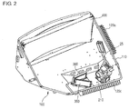
- Fig. 2 is a diagram illustrating the internal configuration of the optical unit 100 according to the embodiment of the present invention. With reference to Fig. 2 , an explanation will be given of the internal configuration of the optical unit 100 in the following.
- the optical unit 100 is provided with an image projection unit 210, an intermediate mirror 350, an intermediate image formation unit 360, and a projection mirror 400 on the inside of a housing 110.
- the image projection unit 210 is provided with three different types of light sources each generating red light, green light, or blue light. The details will follow.
- the light sources can be realized using light emitting diodes (LED) or semiconductor laser light sources. In the present embodiment, a case where LEDs are used as the light sources will be explained.
- the optical unit 100 is provided with a heat sink for cooling the light sources.
- a heat sink 120a that is connected to a red light source
- a heat sink 120b (not shown) that is connected to a green light source
- a heat sink 120c that is connected to a blue light source on the outside of the housing 110.
- the housing 110 is a die case made of aluminum.
- the heat sink 120b and the heat sink 120c for cooling the blue light source and the green light source, respectively, are formed integrally with the housing 110.
- the heat sink 120a for cooling the red light source is installed at a place that is spatially apart from the heat sink 120b and the heat sink 120c and is externally attached separately from the housing 110. Therefore, heat generated by the red light source is transferred to the heat sink 120a via a heat pipe 25.
- Fig. 3 is a diagram schematically illustrating the internal configuration of the image projection unit 210 along with the optical path of the image display light.
- Fig. 4 is a diagram illustrating the optical path of the image display light that is projected on the windshield 610 via the intermediate mirror 350, the intermediate image formation unit 360, and the projection mirror 400.
- the image projection unit 210 is provided with illumination unit 230a, 230b, and 230c (hereinafter, also referred to as illumination units 230 generically), a dichroic cross prism 244, a reflection mirror 236, a field lens 237, a polarization beam splitter 238, a retardation plate 239, an analyzer 241, and a projection lens group 242.
- illumination units 230 also referred to as illumination units 230 generically
- the descriptions regarding the internal configuration of the first illumination unit 230a and the internal configuration of the third illumination unit 230c are omitted, and only the internal configuration of the second illumination unit 230b is shown.
- the illumination units 230 have the same configuration.
- the illumination units 230 are each provided with a light source 231, a collimate lens 232, an ultraviolet-infrared ray (UV-IR) cut filter 233, a polarizer 234, and a fly-eye lens 235.
- the light source 231 consists of a light-emitting diode that emits light of any one of a red color, a green color, and a blue color.
- the first illumination unit 230a has a light-emitting diode that emits red light as a light source.
- the second illumination unit 230b has a light-emitting diode that emits green light as the light source 231.
- the third illumination unit 230c has a light-emitting diode that emits blue light as a light source.
- the light source 231 is attached to a light-source attachment portion 243.
- the light-source attachment portion 243 is combined thermally with a heat sink (not shown) and releases heat that is generated along with the emission of light by the light source 231.
- Light emitted by the light source 231 is changed to parallel light by the collimate lens 232.
- the UV-IR cut filter 233 absorbs and removes ultraviolet light and infrared light from the parallel light passed through the collimate lens 232.
- the polarizer 234 changes light that has passed through the UV-IR cut filter 233 to P-polarized light without disturbance.
- the fly-eye lens 235 then adjusts the brightness of light that has passed through the polarizer 234 to be uniform.
- the reflection mirror 236 changes the optical path of white light that has been synthesized by the dichroic cross prism 244 by 90 degrees.
- Light reflected by the reflection mirror 236 is collected by the field lens 237.
- the light collected by the field lens 237 is radiated to the image display element 240 via the polarization beam splitter 238 and the retardation plate 239, which transmit P-polarized light.
- the image display element 240 is provided with a color filter of a red color, a green color, or a blue color for each pixel.
- the light radiated to the image display element 240 is changed to a color that corresponds to each pixel and modulated by a liquid crystal composition provided on the image display element 240.
- the light then becomes S-polarized image display light and emitted toward the polarization beam splitter 238.
- the emitted S-polarized light is reflected by the polarization beam splitter 238 and enters the projection lens group 242 after changing the optical path and passing through the analyzer 241.
- the image display light transmitted through the projection lens group 242 exits the image projection unit 210 and enters the intermediate mirror 350.
- the intermediate image formation unit 360 has a diffusion screen 362 and a concave lens 364.
- the diffusion screen 362 controls a light distribution angle ⁇ of the image display light traveling to the projection mirror 400 as well as forming a real image based on the image display light passing through the intermediate image formation unit 360.
- the concave lens 364 controls the direction of a principal ray of the image display light traveling to the projection mirror 400 and adjusts an angle ⁇ formed by image display light before passing through the intermediate image formation unit 360 and image display light after passing through the intermediate image formation unit 360.
- the image display light transmitted through the intermediate image formation unit 360 is reflected by the projection mirror 400 and projected on the windshield 610.
- the optical path of the image display light projected on the windshield 610 is changed to be directed toward the user by the windshield 610.
- the windshield 610 functions as a virtual image presenting surface.
- a configuration such as the one described above allows for the user to visually recognize a virtual image, which is based on an image signal output from the control device 50, over the real landscape via the windshield 610.
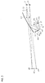
- Fig. 5 is a diagram illustrating optical paths of image display light when a virtual image 450 is presented for viewpoints E1 and E2 of different height levels.
- Fig. 6 is a diagram illustrating image display light that is distributed by the intermediate image formation unit 360 and shows, in an enlarged view, optical paths between the intermediate image formation unit 360 and the projection mirror 400 that are shown in Fig. 5 .
- the viewpoints E1 and E2 of the user change in the vertical direction depending on the height or the seating position of the driver. Even when a viewpoint of the user changes, the entirety of the virtual image 450 from an upper end portion 451 to a lower end portion 452 can be visually recognized preferably. Further, instead of presenting the virtual image 450 right in front of a line-of-sight direction C1 or C2 in which the user looks in the forward direction of the vehicle, presenting the virtual image 450 at a position that is shifted in the vertical direction allows the user to refer to the virtual image 450 by slightly shifting the direction of the line of sight when necessary, thus ensuring the user-friendliness.
- the diffusion screen 362 and the concave lens 364 as the intermediate image formation unit 360, the direction of a principal ray and the light distribution angle of the image display light that has passed through the intermediate image formation unit 360 are controlled, and the visibility of the virtual image 450 is increased.
- the presentation position of the virtual image 450 can be shifted in the vertical direction, and the virtual image 450 can be presented at an easily viewable position.
- a configuration is shown for a case where the virtual image 450 is presented downward with respect to the line-of-sight directions C1 and C2.
- the virtual image 450 may be presented at a different position.
- the first viewpoint E1 is an upper limit position that allows the entirety of the virtual image 450 to be visually recognized
- the second viewpoint E2 is a lower limit position that allows the entirety of the virtual image 450 to be visually recognized. Therefore, the user is able to visually recognize the entirety of the virtual image 450 as long as the user's viewpoint is in a range between the first viewpoint E1 and the second viewpoint E2.
- light A1 and light A2 that are shown by solid lines represent light rays for presenting the user the upper end portion 451 of the virtual image 450, and light that is emitted from an upper end portion 371 of a real image 370 formed in the intermediate image formation unit 360 is reflected on the projection mirror 400 and the windshield 610 and reaches the user's viewpoints E1 and E2.
- the light A1 that is traveling to the first viewpoint E1 is reflected at a first reflection position 401 of the projection mirror 400
- the light A2 that is traveling to the second viewpoint E2 is reflected at a second reflection position 402 of the projection mirror 400.
- a configuration is employed where image display light is reflected on the projection mirror 400 and the windshield 610.
- a real image that is vertically flipped is formed in the intermediate image formation unit 360.
- light B1 and light B2 that are shown by broken lines represent light rays for presenting the user the lower end portion 452 of the virtual image 450, and light that is emitted from a lower end portion 372 of the real image 370 formed in the intermediate image formation unit 360 is reflected on the projection mirror 400 and the windshield 610 and reaches the viewpoints E1 and E2.
- the light B1 that is traveling to the first viewpoint E1 is reflected at a third reflection position 403 of the projection mirror 400
- the light B2 that is traveling to the second viewpoint E2 is reflected at a fourth reflection position 404 of the projection mirror 400.
- Fig. 6 shows, in an enlarged view, the optical paths between the intermediate image formation unit 360 and the projection mirror 400 that are shown in Fig. 5 .
- Light A that forms an image as the upper end portion 371 of the real image 370 enters the concave lens 364, changes the direction in the upward direction (y direction) by an angle ⁇ 1 , and becomes transmitted based on a direction that is perpendicular to the diffusion screen 362.
- the light A forms an image as a real image and becomes diffused on the diffusion screen 362 and travels to the projection mirror 400 as image display light having a light distribution angle ⁇ 1 .
- the light A that enters the intermediate image formation unit 360 becomes image display light that is distributed between light A1 traveling to the first reflection position 401 and light A2 traveling to the second reflection position 402, centering around a principal ray A0.
- light B that forms an image as the lower end portion 372 of the real image 370 enters the concave lens 364, changes the direction in the upward direction (y direction) by an angle ⁇ 2 , and becomes transmitted.
- the light A forms an image as a real image and becomes diffused on the diffusion screen 362 and travels to the projection mirror 400 as image display light having a light distribution angle ⁇ 2 .
- the light B that enters the intermediate image formation unit 360 becomes image display light that is distributed between light B1 traveling to the third reflection position 403 and light B2 traveling to the fourth reflection position 404, centering around a principal ray B0.
- the concave lens 364 is provided eccentrically in the vertical direction (the vertical direction in Fig. 4 ) based on the z direction. More specifically, the positon of an optical axis of the concave lens 364 is located below the center position of the diffusion screen 362. Therefore, the angle ⁇ 2 of the principal ray B0 emitted from the lower end portion 372, which is far away from the optical axis of the concave lens 364, is larger than the angle ⁇ 1 of the principal ray A0 emitted from the upper end portion 371, which is close to the optical axis of the concave lens 364.
- the concave lens 364 is formed such that the optical axis of the concave lens 364 is not included in a concave surface thereof.
- the principal rays A 0 and B 0 are both emitted in a tilted manner toward the upward direction (y direction).
- Fig. 7 is a diagram illustrating the configuration of the diffusion screen 362.
- the diffusion screen 362 which is a transmission-type screen, is provided with two light diffusion plates 363a and 363b.
- the two light diffusion plates 363a and 363b are layered in such a direction that light diffusion surfaces 367a and 367b on which diffusion beads 369a and 369b are respectively provided face each other.
- the degree of difference is reduced between an incident angle ⁇ in of light entering the diffusion screen 362 and an emission angle ⁇ out of a principal ray of diffused light emitted from the diffusion screen 362 by arranging the light diffusion surfaces 367a and 367b to face each other.
- the diffusion screen 362 properly adjusts the emission angle ⁇ out of the principal ray of the diffused light and presents an image that is highly visible to the user.
- the diffusion screen 362 is provided with a first light diffusion plate 363a and a second light diffusion plate 363b.
- the first light diffusion plate 363a has a first base member 366a and a plurality of first diffusion beads 369a.
- the first base member 366a has a first light diffusion surface 367a and a first flat surface 368a that face each other.
- the second light diffusion plate 363b has a second base member 366b and a plurality of second diffusion beads 369b
- the second base member 366b has a second light diffusion surface 367b and a second flat surface 368b that face each other.
- the first base member 366a and the second base member 366b are flat plates formed of transparent resin materials or the like. Flexible transparent films may be used as the base members 366.
- the first diffusion beads 369a and the second diffusion beads 369b are highly-transparent optical beads, and the diameter thereof is 10 micrometers or less.
- the diffusion beads 369 are applied on the first light diffusion surface 367a and the second light diffusion surface 367b (hereinafter, also referred to as light diffusion surfaces 367, generically) in a thickness of 10 to 15 micrometers.
- light diffusion plates 363 having the same light diffusion capability are used as the first light diffusion plate 363a and the second light diffusion plate 363b. Therefore, the first light diffusion plate 363a and the second light diffusion plate 363b that are provided to face each other diffuse light in the same light distribution. Having an identical light distribution means having optical properties that allow the intensity distribution of transmitted light to be almost identical when light having a specific intensity distribution becomes incident.
- Figs. 8A and 8B are diagrams illustrating the relationship between an incident angle ⁇ in of light incident on a light diffusion plate 363 and emission angles ⁇ out1 and ⁇ out2 of light passing through the light diffusion plate 363.
- Fig. 8A shows a case where light becomes incident on a light diffusion surface 367, which is a bead surface
- Fig. 8B shows a case where light becomes incident on a flat surface 368, which is not a bead surface.
- the angle of a principal ray changes to an emission angle ⁇ out1 , which is larger by ⁇ 1 with respect to the incident angle ⁇ in .
- the angle of a principal ray changes to an emission angle ⁇ out2 , which is smaller by ⁇ 2 with respect to the incident angle ⁇ in .
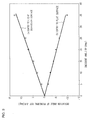
- Fig. 9 is a graph illustrating the relationship between the angle of light incident on a light diffusion plate 363 and a deviation angle of a principal ray emitted from the light diffusion plate 363.
- a straight line shown by (a) shows a deviation angle ⁇ 1 occurring when light enters the light diffusion surface 367, which is a bead surface, and corresponds to a case where light enters as shown in Fig. 8A .
- a straight line shown by (b) shows a deviation angle ⁇ 2 occurring when light enters through the flat surface 368, which is not a bead surface, and corresponds to a case where light enters as shown in Fig. 8B .
- Fig. 9 is a graph illustrating the relationship between the angle of light incident on a light diffusion plate 363 and a deviation angle of a principal ray emitted from the light diffusion plate 363.
- a straight line shown by (a) shows a deviation angle ⁇ 1 occurring when light enters the light diffusion surface 367, which is a bea
- the value of the deviation angle ⁇ is found to become larger as the incident angle ⁇ in becomes larger in both the case of (a) where light enters the light diffusion surface 367 and the case of (b) where light enters the flat surface 368.
- the size of the deviation angle ⁇ with respect to the incident angle ⁇ in is found to be almost the same although the positive or negative sign of the deviation angle ⁇ is different.
- the angle of a principal ray of emitted light changes when light enters the diffusion screen at an angle.
- the direction of the principal ray changes due to the light diffusion plate 363, which is used independently, and the visibility of image display light that is presented to the user may be lowered.
- the first light diffusion plate 363a and the second light diffusion plate 363b which exhibit the same light distribution, are combined such that the respective light diffusion surfaces 367a and 367b face each other. Therefore, even when a deviation angle occurs between an incident angle and an emission angle in each of the first light diffusion plate 363a and the second light diffusion plate 363b, a deviation angle caused by the first light diffusion plate 363a can be corrected by a deviation angle caused by the second light diffusion plate 363b. This is because, as shown in Fig.
- the intermediate image formation unit 360 in the present embodiment has a diffusion screen 362 that controls the light distribution angle of a principal ray such that image display light is realized that has predetermined light distribution angles ⁇ 1 and ⁇ 2 with respect to principal rays A0 and B0, respectively. Therefore, a virtual image with a certain level of brightness can be presented even when the line-of-sight position is moved as long as the line-of-sight position is moved within a predetermined range.
- the image display light can be utilized highly efficiently. If the light distribution angles are narrower than these reflection position ranges, the range of a viewpoint where the virtual image 450 is able to be presented in a bright manner becomes narrow. On the other hand, if the light distribution angles are wider than these reflection position ranges, the proportion of image display light that is not reflected by the projection mirror 400 increases, and the virtual image 450 presented to the user thus becomes dark. As described, by properly controlling the light distribution angles ⁇ 1 and ⁇ 2 , the virtual image 450 can be presented to the user in a bright manner with high efficiency, and the visibility of the virtual image 450 can be increased.
- the intermediate image formation unit 360 has a concave lens 364 that controls the respective directions of the principal rays A0 and B0 that have passed through the intermediate image formation unit 360.
- the concave lens 364 as the intermediate image formation unit 360, the virtual image 450 that is presented to the user can be further enlarged even when a distance D between the intermediate image formation unit 360 and the projection mirror 400 has to be shortened. Therefore, by providing the concave lens 364, a larger virtual image 450 can be presented while the size of the optical unit 100 is reduced, and the visibility of the virtual image 450 can be increased.
- the concave lens 364 is provided eccentrically in the vertical direction.
- the virtual image 450 can be presented at a position that is shifted slightly in the vertical direction. This is because an angular difference can be provided between light for presenting an upper end portion 451 of the virtual image 450 and light for presenting a lower end portion 452 of the virtual image 450.
- the virtual image 450 can be presented at a position that can be easily viewed by the user, and the visibility of the virtual image 450 can be increased.
- the optical unit 100 can be further downsized.
- the diffusion screen 362 two light diffusion plates 363a and 363b on which light diffusion surfaces 367a and 367b, which are bead surfaces, are layered respectively to face each other are used as the diffusion screen 362.
- the respective light diffusion surfaces 367a and 367b of the two light diffusion plates 363a and 363b are layered to face each other.
- a configuration where the flat surfaces 368a and 368b are layered to face each other is a possible configuration of the diffusion screen 362.
- a distance between the first light diffusion surface 367a and the second light diffusion surface 367b on which image display light forms an image is large.
- image display light forms an image on each of the first light diffusion surface 367a and the second light diffusion surface 367b, resulting in the generation of a double image on the diffusion screen 362; thus, visibility to the user is lowered.
- the generation of a double image can be prevented, and the visibility of a virtual image 450 can be increased.
- a concave lens 364 is arranged in front of a diffusion screen 362 as an intermediate image formation unit 360, i.e., a case is shown where image display light that pas passed through the concave lens 364 enters the diffusion screen 362.
- the diffusion screen 362 and the concave lens 364 may be arranged reversely.
- optical elements are arrayed in the order of an intermediate mirror 350, a diffusion screen 362, a concave lens 364, and a projection mirror 400 between the intermediate mirror 350 and the projection mirror 400.
- a virtual image 450 with high visibility can be presented by controlling the light distribution angle of image display light by the diffusion screen 362 and by controlling the direction of a principal ray by the concave lens 364.
- the direction of a principal ray of image display light is controlled by using the concave lens 364 as the intermediate image formation unit 360.
- the intermediate image formation unit 360 may be provided with only the diffusion screen 362 without providing the concave lens 364.
- the direction of a principal ray of image display light is adjusted by a projection lens group 242 provided in an image projection unit 210. Also in this case, changes in the direction of a principal ray before and after passing through the diffusion screen 362 can be suppressed.
- image display light with a maintained direction of a principal ray that is determined by the projection lens group 242 can be presented. This allows a highly-visible virtual image 450 to be presented.
- a light diffusion plate that has a bead surface on which a plurality of diffusion beads 369 are provided is used as a light diffusion plate 363 that forms the diffusion screen 362.
- a light diffusion plate on which diffusion beads are not used may be used in an exemplary variation.
- respective microlens arrays of two light diffusion plates are layered to face each other.
- the generation of a double image can be prevented.
- the visibility of a virtual image 450 can be increased.
- a base member that is provided with light diffusivity by performing surface roughening on a light diffusion surface may be used as a light diffusion plate.
- a diffusion screen 362 that is used in an intermediate image formation unit 360 used for a head-up display.
- the above-described diffusion screen 362 may be used as a screen for rear projection television. Since changes in the direction of a principal ray before and after passing through the diffusion screen 362 can be suppressed, a highly-visible image can be provided.
- Transmission-type screens according to the present invention allow the visibility of a projected image to be increased.
Abstract
Description
- The present invention relates to transmission-type screens and image display devices using the transmission-type screens.
- Display devices for vehicles called head-up displays are known. Head-up displays are display devices that display information over a landscape outside a vehicle by allowing light entering from outside the vehicle to pass through and reflecting, on a windshield or the like of the vehicle, an image projected from an optical unit arranged inside the vehicle. Head-up displays have received attention as display devices for vehicles in recent years since head-up displays allow a driver who is visually recognizing a view outside a vehicle to recognize information of an image projected from an optical unit almost without changing the line of sight or a focus.
- Image display light projected from the optical unit once forms an image on a transmission-type screen, and the image formed on the screen is presented to the user. As such a transmission-type screen, a configuration is disclosed where two light diffusion plates are layered (reference is made to, for example, Patent Document 1).
- [Patent Document 1] Japanese Patent Application Publication Number
2003-98601 - The user recognizes the image via the transmission-type screen. Thus, the transmission-type screen is highly visible, desirably.
- In this background, a purpose of the present invention is to provide transmission-type screens with enhanced visibility.
- A transmission-type screen according to one embodiment of the present invention includes: two light diffusion plates that have respective flat surfaces and respective light diffusion surfaces that face the respective flat surfaces and diffuse and transmit incident light. The two light diffusion plates are layered such that the respective light diffusion surfaces face each other, and the light diffusion surfaces diffuse light that is incident on the respective light diffusion surfaces in substantially the same light distribution.
- Another embodiment of the present invention relates to an image display device. This device includes: an image projection unit that projects image display light; an intermediate image formation unit that forms a real image that is based on the image display light projected from the image projection unit; and a projection mirror that reflects, toward a virtual image presenting surface, the image display light that has passed through the intermediate image formation unit. The intermediate image formation unit includes two light diffusion plates that have respective flat surfaces and respective light diffusion surfaces that face the respective flat surfaces and diffuse and transmit incident light. The two light diffusion plates are layered such that the respective light diffusion surfaces face each other, and the light diffusion surfaces diffuse light that is incident on the respective light diffusion surfaces in substantially the same light distribution.
- Transmission-type screens according to the present invention allow the visibility of a projected image to be increased.
-
-
Fig. 1 is a diagram schematically illustrating a form of installation of a head-up display according to an embodiment of the present invention; -
Fig. 2 is a diagram illustrating the internal configuration of an optical unit; -
Fig. 3 is a diagram schematically illustrating the internal configuration of an image projection unit; -
Fig. 4 is a diagram illustrating an optical path of image display light that is projected on a windshield; -
Fig. 5 is a diagram illustrating optical paths of image display light when a virtual image is presented for viewpoints of different height levels; -
Fig. 6 is a diagram illustrating image display light that is distributed by an intermediate image formation unit; -
Fig. 7 is a diagram illustrating the configuration of a diffusion screen; -
Figs. 8A and 8B are diagrams illustrating the relationship between the angle of light incident on a light diffusion plate and the angle of light passing through the light diffusion plate; and -
Fig. 9 is a graph illustrating the relationship between the angle of light incident on a light diffusion plate and a deviation angle of a principal ray emitted from the light diffusion plate. - Described below is an explanation of the embodiments of the present invention with reference to figures. Specific numerical values and the like shown in the embodiments are shown merely for illustrative purposes to facilitate understanding of the invention and do not intend to limit the scope of the present invention, unless otherwise noted. In the subject specification and figures, elements having substantially the same functions and structures shall be denoted by the same reference numerals, and duplicative explanations will be omitted appropriately. Also, the illustration of elements that are not directly related to the present invention is omitted.
- An explanation will be given using a head-
up display 10, which is installed and used inside a dashboard of a vehicle, as an example for an image display device according to an embodiment.Fig. 1 is a diagram schematically illustrating a form of installation of the head-updisplay 10 according to the embodiment of the present invention. The head-updisplay 10 includes anoptical unit 100 and acontrol device 50.Fig. 1 is a diagram illustrating a case where theoptical unit 100 is arranged and used inside a left-side dashboard based on a travelling direction (leftward direction inFig. 1 ) of a vehicle. The following embodiment shows an example where the head-updisplay 10 is arranged for a driver of a left-hand drive vehicle. For a right-hand drive vehicle, the internal configuration of theoptical unit 100 may be horizontally flipped based on a travelling direction of the vehicle. With reference toFig. 1 , an explanation will be given of the outline of the head-updisplay 10 in the following. - A
control device 50 is provided with a central processing unit (CPU) (not shown) and generates an image signal used for display on theoptical unit 100. Thecontrol device 50 is also provided with an external input interface (not shown). An image signal output from an external device (not shown) such as a navigation device, a media reproduction device, or the like is input to thecontrol device 50, and thecontrol device 50 is also capable of outputting the image signal to theoptical unit 100 after performing a predetermined process on the signal that has been input. - The
optical unit 100 generates image display light that is displayed as avirtual image 450 on awindshield 610 based on the image signal generated by thecontrol device 50. Therefore, theoptical unit 100 is provided with animage projection unit 210, anintermediate mirror 350, an intermediateimage formation unit 360, and aprojection mirror 400 inside ahousing 110. - The
image projection unit 210 houses a light source, an image display element, various optical lenses, and the like. Theimage projection unit 210 generates image display light based on the image signal output from thecontrol device 50 and projects the image display light. In the present embodiment, a case where a liquid crystal on silicon (LCOS), which is a reflection type liquid crystal display panel, is used as an image display element is illustrated for example. However, a digital micromirror device (DMD) may be used as the image display element. In that case, the DMD is assumed to be formed by an optical system and a drive circuit according to a display element to which the DMD is applied. - The image display light projected by the
image projection unit 210 is reflected by theintermediate mirror 350. The image display light reflected by theintermediate mirror 350 forms an image in the intermediateimage formation unit 360. The image display light related to a real image formed in the intermediateimage formation unit 360 is transmitted through the intermediateimage formation unit 360 and projected on theprojection mirror 400. - The
projection mirror 400 is a concave mirror, and the image display light transmitted through the intermediateimage formation unit 360 is enlarged and projected on thewindshield 610 by theprojection mirror 400. The optical path of the image display light projected on thewindshield 610 is changed to be directed toward the user by thewindshield 610. A user E, who is the driver, recognizes the image display light reflected by thewindshield 610 as avirtual image 450 in front of thewindshield 610 in the direction of the line of sight. -
Fig. 2 is a diagram illustrating the internal configuration of theoptical unit 100 according to the embodiment of the present invention. With reference toFig. 2 , an explanation will be given of the internal configuration of theoptical unit 100 in the following. - As described above, the
optical unit 100 is provided with animage projection unit 210, anintermediate mirror 350, an intermediateimage formation unit 360, and aprojection mirror 400 on the inside of ahousing 110. Theimage projection unit 210 is provided with three different types of light sources each generating red light, green light, or blue light. The details will follow. The light sources can be realized using light emitting diodes (LED) or semiconductor laser light sources. In the present embodiment, a case where LEDs are used as the light sources will be explained. - The light sources generate heat during use. Therefore, the
optical unit 100 is provided with a heat sink for cooling the light sources. There are three types of light sources. Thus, in order to cool these light sources, theoptical unit 100 is provided with aheat sink 120a that is connected to a red light source, a heat sink 120b (not shown) that is connected to a green light source, and aheat sink 120c that is connected to a blue light source on the outside of thehousing 110. - The
housing 110 is a die case made of aluminum. The heat sink 120b and theheat sink 120c for cooling the blue light source and the green light source, respectively, are formed integrally with thehousing 110. On the other hand, theheat sink 120a for cooling the red light source is installed at a place that is spatially apart from the heat sink 120b and theheat sink 120c and is externally attached separately from thehousing 110. Therefore, heat generated by the red light source is transferred to theheat sink 120a via aheat pipe 25. - An explanation will now be given regarding the optical system of the head-up
display 10 with reference toFig. 3 andFig. 4 .Fig. 3 is a diagram schematically illustrating the internal configuration of theimage projection unit 210 along with the optical path of the image display light.Fig. 4 is a diagram illustrating the optical path of the image display light that is projected on thewindshield 610 via theintermediate mirror 350, the intermediateimage formation unit 360, and theprojection mirror 400. - With reference to
Fig. 3 , an explanation will be given of the internal configuration of theimage projection unit 210. Theimage projection unit 210 is provided withillumination unit illumination units 230 generically), a dichroic cross prism 244, areflection mirror 236, afield lens 237, apolarization beam splitter 238, aretardation plate 239, ananalyzer 241, and aprojection lens group 242. InFig. 3 , the descriptions regarding the internal configuration of thefirst illumination unit 230a and the internal configuration of thethird illumination unit 230c are omitted, and only the internal configuration of thesecond illumination unit 230b is shown. However, theillumination units 230 have the same configuration. - The
illumination units 230 are each provided with alight source 231, acollimate lens 232, an ultraviolet-infrared ray (UV-IR) cutfilter 233, apolarizer 234, and a fly-eye lens 235. Thelight source 231 consists of a light-emitting diode that emits light of any one of a red color, a green color, and a blue color. Thefirst illumination unit 230a has a light-emitting diode that emits red light as a light source. Thesecond illumination unit 230b has a light-emitting diode that emits green light as thelight source 231. Thethird illumination unit 230c has a light-emitting diode that emits blue light as a light source. - The
light source 231 is attached to a light-source attachment portion 243. The light-source attachment portion 243 is combined thermally with a heat sink (not shown) and releases heat that is generated along with the emission of light by thelight source 231. Light emitted by thelight source 231 is changed to parallel light by thecollimate lens 232. The UV-IR cut filter 233 absorbs and removes ultraviolet light and infrared light from the parallel light passed through thecollimate lens 232. Thepolarizer 234 changes light that has passed through the UV-IR cut filter 233 to P-polarized light without disturbance. The fly-eye lens 235 then adjusts the brightness of light that has passed through thepolarizer 234 to be uniform. - Light that has passed through respective fly-
eye lenses 235 of theillumination units 230 enter the dichroic cross prism 244 from different directions. Red light, green light, and blue light that have entered the dichroic cross prism 244 become white light in which the three colors are combined and travel to thereflection mirror 236. Thereflection mirror 236 changes the optical path of white light that has been synthesized by the dichroic cross prism 244 by 90 degrees. Light reflected by thereflection mirror 236 is collected by thefield lens 237. The light collected by thefield lens 237 is radiated to theimage display element 240 via thepolarization beam splitter 238 and theretardation plate 239, which transmit P-polarized light. - The
image display element 240 is provided with a color filter of a red color, a green color, or a blue color for each pixel. The light radiated to theimage display element 240 is changed to a color that corresponds to each pixel and modulated by a liquid crystal composition provided on theimage display element 240. The light then becomes S-polarized image display light and emitted toward thepolarization beam splitter 238. The emitted S-polarized light is reflected by thepolarization beam splitter 238 and enters theprojection lens group 242 after changing the optical path and passing through theanalyzer 241. The image display light transmitted through theprojection lens group 242 exits theimage projection unit 210 and enters theintermediate mirror 350. - With reference to
Fig. 4 , an explanation will be given regarding the optical path of the image display light that is projected on thewindshield 610 via the intermediateimage formation unit 360 and theprojection mirror 400 from theintermediate mirror 350. The optical path of the image display light emitted from theprojection lens group 242 of theimage projection unit 210 is changed to an optical path that is traveling to theprojection mirror 400 by theintermediate mirror 350. In the meantime, a real image based on the image display light reflected by theintermediate mirror 350 is formed in the intermediateimage formation unit 360. - The intermediate
image formation unit 360 has adiffusion screen 362 and aconcave lens 364. Thediffusion screen 362 controls a light distribution angle ψ of the image display light traveling to theprojection mirror 400 as well as forming a real image based on the image display light passing through the intermediateimage formation unit 360. Theconcave lens 364 controls the direction of a principal ray of the image display light traveling to theprojection mirror 400 and adjusts an angle θ formed by image display light before passing through the intermediateimage formation unit 360 and image display light after passing through the intermediateimage formation unit 360. - The image display light transmitted through the intermediate
image formation unit 360 is reflected by theprojection mirror 400 and projected on thewindshield 610. The optical path of the image display light projected on thewindshield 610 is changed to be directed toward the user by thewindshield 610. Thereby, as described above, the user is able to visually recognize a virtual image based on the image display light in the forward direction via thewindshield 610. Therefore, thewindshield 610 functions as a virtual image presenting surface. - A configuration such as the one described above allows for the user to visually recognize a virtual image, which is based on an image signal output from the
control device 50, over the real landscape via thewindshield 610. - With reference to
Fig. 5 andFig. 6 , functions of the intermediateimage formation unit 360 according to the present embodiment will be described in detail.Fig. 5 is a diagram illustrating optical paths of image display light when avirtual image 450 is presented for viewpoints E1 and E2 of different height levels.Fig. 6 is a diagram illustrating image display light that is distributed by the intermediateimage formation unit 360 and shows, in an enlarged view, optical paths between the intermediateimage formation unit 360 and theprojection mirror 400 that are shown inFig. 5 . - As shown in
Fig. 5 , the viewpoints E1 and E2 of the user, who is the driver, change in the vertical direction depending on the height or the seating position of the driver. Even when a viewpoint of the user changes, the entirety of thevirtual image 450 from anupper end portion 451 to a lower end portion 452 can be visually recognized preferably. Further, instead of presenting thevirtual image 450 right in front of a line-of-sight direction C1 or C2 in which the user looks in the forward direction of the vehicle, presenting thevirtual image 450 at a position that is shifted in the vertical direction allows the user to refer to thevirtual image 450 by slightly shifting the direction of the line of sight when necessary, thus ensuring the user-friendliness. - In the present embodiment, by combining the
diffusion screen 362 and theconcave lens 364 as the intermediateimage formation unit 360, the direction of a principal ray and the light distribution angle of the image display light that has passed through the intermediateimage formation unit 360 are controlled, and the visibility of thevirtual image 450 is increased. In particular, by providing theconcave lens 364 eccentrically in the vertical direction, the presentation position of thevirtual image 450 can be shifted in the vertical direction, and thevirtual image 450 can be presented at an easily viewable position. In the present embodiment, a configuration is shown for a case where thevirtual image 450 is presented downward with respect to the line-of-sight directions C1 and C2. However, by changing the state of eccentricity of theconcave lens 364, thevirtual image 450 may be presented at a different position. - First, differences in a path of image display light according to differences between the viewpoint E1 and the viewpoint E2 are described in detail with reference to
Fig. 5 . The first viewpoint E1 is an upper limit position that allows the entirety of thevirtual image 450 to be visually recognized, and the second viewpoint E2 is a lower limit position that allows the entirety of thevirtual image 450 to be visually recognized. Therefore, the user is able to visually recognize the entirety of thevirtual image 450 as long as the user's viewpoint is in a range between the first viewpoint E1 and the second viewpoint E2. - In
Fig. 5 , light A1 and light A2 that are shown by solid lines represent light rays for presenting the user theupper end portion 451 of thevirtual image 450, and light that is emitted from anupper end portion 371 of areal image 370 formed in the intermediateimage formation unit 360 is reflected on theprojection mirror 400 and thewindshield 610 and reaches the user's viewpoints E1 and E2. The light A1 that is traveling to the first viewpoint E1 is reflected at afirst reflection position 401 of theprojection mirror 400, and the light A2 that is traveling to the second viewpoint E2 is reflected at asecond reflection position 402 of theprojection mirror 400. In an optical system shown in the present embodiment, a configuration is employed where image display light is reflected on theprojection mirror 400 and thewindshield 610. Thus, a real image that is vertically flipped is formed in the intermediateimage formation unit 360. - On the other hand, light B1 and light B2 that are shown by broken lines represent light rays for presenting the user the lower end portion 452 of the
virtual image 450, and light that is emitted from alower end portion 372 of thereal image 370 formed in the intermediateimage formation unit 360 is reflected on theprojection mirror 400 and thewindshield 610 and reaches the viewpoints E1 and E2. The light B1 that is traveling to the first viewpoint E1 is reflected at athird reflection position 403 of theprojection mirror 400, and the light B2 that is traveling to the second viewpoint E2 is reflected at afourth reflection position 404 of theprojection mirror 400. - Then, image display light that is distributed in the vertical direction by the intermediate
image formation unit 360 will be described in detail with reference toFig. 6. Fig. 6 shows, in an enlarged view, the optical paths between the intermediateimage formation unit 360 and theprojection mirror 400 that are shown inFig. 5 . Light A that forms an image as theupper end portion 371 of thereal image 370 enters theconcave lens 364, changes the direction in the upward direction (y direction) by an angle θ1, and becomes transmitted based on a direction that is perpendicular to thediffusion screen 362. Then, the light A forms an image as a real image and becomes diffused on thediffusion screen 362 and travels to theprojection mirror 400 as image display light having a light distribution angle ψ1. As a result, the light A that enters the intermediateimage formation unit 360 becomes image display light that is distributed between light A1 traveling to thefirst reflection position 401 and light A2 traveling to thesecond reflection position 402, centering around a principal ray A0. - Similarly, light B that forms an image as the
lower end portion 372 of thereal image 370 enters theconcave lens 364, changes the direction in the upward direction (y direction) by an angle θ2, and becomes transmitted. Then, the light A forms an image as a real image and becomes diffused on thediffusion screen 362 and travels to theprojection mirror 400 as image display light having a light distribution angle ψ2. As a result, the light B that enters the intermediateimage formation unit 360 becomes image display light that is distributed between light B1 traveling to thethird reflection position 403 and light B2 traveling to thefourth reflection position 404, centering around a principal ray B0. - The
concave lens 364 according to the present embodiment is provided eccentrically in the vertical direction (the vertical direction inFig. 4 ) based on the z direction. More specifically, the positon of an optical axis of theconcave lens 364 is located below the center position of thediffusion screen 362. Therefore, the angle θ2 of the principal ray B0 emitted from thelower end portion 372, which is far away from the optical axis of theconcave lens 364, is larger than the angle θ1 of the principal ray A0 emitted from theupper end portion 371, which is close to the optical axis of theconcave lens 364. Theconcave lens 364 according to the present embodiment is formed such that the optical axis of theconcave lens 364 is not included in a concave surface thereof. Thus, the principal rays A0 and B0 are both emitted in a tilted manner toward the upward direction (y direction). - Then, with reference to
Fig. 7 , a description will be made in detail regarding thediffusion screen 362 in the present embodiment.Fig. 7 is a diagram illustrating the configuration of thediffusion screen 362. Thediffusion screen 362, which is a transmission-type screen, is provided with twolight diffusion plates light diffusion plates light diffusion surfaces diffusion beads diffusion screen 362, the degree of difference is reduced between an incident angle θin of light entering thediffusion screen 362 and an emission angle θout of a principal ray of diffused light emitted from thediffusion screen 362 by arranging thelight diffusion surfaces diffusion screen 362 properly adjusts the emission angle θout of the principal ray of the diffused light and presents an image that is highly visible to the user. - The
diffusion screen 362 is provided with a firstlight diffusion plate 363a and a secondlight diffusion plate 363b. The firstlight diffusion plate 363a has afirst base member 366a and a plurality offirst diffusion beads 369a. Thefirst base member 366a has a firstlight diffusion surface 367a and a firstflat surface 368a that face each other. Similarly, the secondlight diffusion plate 363b has asecond base member 366b and a plurality ofsecond diffusion beads 369b, and thesecond base member 366b has a secondlight diffusion surface 367b and a secondflat surface 368b that face each other. - The
first base member 366a and thesecond base member 366b (hereinafter, also referred to asbase members 366, generically) are flat plates formed of transparent resin materials or the like. Flexible transparent films may be used as thebase members 366. Thefirst diffusion beads 369a and thesecond diffusion beads 369b (hereinafter, also referred to as diffusion beads 369, generically) are highly-transparent optical beads, and the diameter thereof is 10 micrometers or less. The diffusion beads 369 are applied on the firstlight diffusion surface 367a and the secondlight diffusion surface 367b (hereinafter, also referred to as light diffusion surfaces 367, generically) in a thickness of 10 to 15 micrometers. - In the present embodiment, light diffusion plates 363 having the same light diffusion capability are used as the first
light diffusion plate 363a and the secondlight diffusion plate 363b. Therefore, the firstlight diffusion plate 363a and the secondlight diffusion plate 363b that are provided to face each other diffuse light in the same light distribution. Having an identical light distribution means having optical properties that allow the intensity distribution of transmitted light to be almost identical when light having a specific intensity distribution becomes incident. - Then, with reference to
Figs. 8A and 8B andFig. 9 , an explanation will be given regarding the optical properties of the light diffusion plates 363 forming thediffusion screen 362.Figs. 8A and 8B are diagrams illustrating the relationship between an incident angle θin of light incident on a light diffusion plate 363 and emission angles θout1 and θout2 of light passing through the light diffusion plate 363.Fig. 8A shows a case where light becomes incident on alight diffusion surface 367, which is a bead surface, andFig. 8B shows a case where light becomes incident on a flat surface 368, which is not a bead surface. When letting light to enter through thelight diffusion surface 367, which is a bead surface, the angle of a principal ray changes to an emission angle θout1, which is larger by Δθ1 with respect to the incident angle θin. On the other hand, when letting light to enter through the flat surface 368, which is not a bead surface, the angle of a principal ray changes to an emission angle θout2, which is smaller by Δθ2 with respect to the incident angle θin. This is because the way of change in angle is different in a case where the angle of light changes when entering a diffusion bead 369, which forms a spherical surface, and in a case where the angle of light changes when being emitted from the diffusion bead 369. -
Fig. 9 is a graph illustrating the relationship between the angle of light incident on a light diffusion plate 363 and a deviation angle of a principal ray emitted from the light diffusion plate 363. A straight line shown by (a) shows a deviation angle Δθ1 occurring when light enters thelight diffusion surface 367, which is a bead surface, and corresponds to a case where light enters as shown inFig. 8A . On the other hand, a straight line shown by (b) shows a deviation angle Δθ2 occurring when light enters through the flat surface 368, which is not a bead surface, and corresponds to a case where light enters as shown inFig. 8B . InFig. 9 , with regard to whether a deviation angle Δθ is positive or negative, the deviation angle Δθ has a positive value when an emission angle θout is larger than an incident angle θin and has a negative value when the emission angle θout is smaller than the incident angle θin, and a relationship, θout =θin + Δθ, is satisfied. - As shown in
Fig. 9 , the value of the deviation angle Δθ is found to become larger as the incident angle θin becomes larger in both the case of (a) where light enters thelight diffusion surface 367 and the case of (b) where light enters the flat surface 368. In the case of (a) where light enters thelight diffusion surface 367 and in the case of (b) where light enters the flat surface 368, the size of the deviation angle Δθ with respect to the incident angle θin is found to be almost the same although the positive or negative sign of the deviation angle Δθ is different. - According to optical properties shown in
Fig. 9 , if only one light diffusion plate 363 is used as a diffusion screen, the angle of a principal ray of emitted light changes when light enters the diffusion screen at an angle. In that case, even when the direction of the principal ray is properly controlled by theconcave lens 364, the direction of the principal ray changes due to the light diffusion plate 363, which is used independently, and the visibility of image display light that is presented to the user may be lowered. - Meanwhile, in the
diffusion screen 362 according to the present embodiment, the firstlight diffusion plate 363a and the secondlight diffusion plate 363b, which exhibit the same light distribution, are combined such that the respectivelight diffusion surfaces light diffusion plate 363a and the secondlight diffusion plate 363b, a deviation angle caused by the firstlight diffusion plate 363a can be corrected by a deviation angle caused by the secondlight diffusion plate 363b. This is because, as shown inFig. 7 , light that enters the firstflat surface 368a of the firstlight diffusion plate 363a is emitted from thelight diffusion surface 367a at an emission angle that is smaller than its incident angle by a deviation angle Δθ, and the light that then directly enters the secondlight diffusion surface 367b of the secondlight diffusion plate 363b is emitted from the secondflat surface 368b at an emission angle that is larger than its incident angle by the deviation angle Δθ. - A description will be given in the following regarding effects that are achieved by the intermediate
image formation unit 360 in the present embodiment. - The intermediate
image formation unit 360 in the present embodiment has adiffusion screen 362 that controls the light distribution angle of a principal ray such that image display light is realized that has predetermined light distribution angles ψ1 and ψ2 with respect to principal rays A0 and B0, respectively. Therefore, a virtual image with a certain level of brightness can be presented even when the line-of-sight position is moved as long as the line-of-sight position is moved within a predetermined range. Also, by selecting, as thediffusion screen 362, a diffusion screen having characteristics where light distribution angles ψ1 and ψ2 fall within a range from thefirst reflection position 401 to thesecond reflection position 402 of theprojection mirror 400 or a range from thethird reflection position 403 to thefourth reflection position 404, the image display light can be utilized highly efficiently. If the light distribution angles are narrower than these reflection position ranges, the range of a viewpoint where thevirtual image 450 is able to be presented in a bright manner becomes narrow. On the other hand, if the light distribution angles are wider than these reflection position ranges, the proportion of image display light that is not reflected by theprojection mirror 400 increases, and thevirtual image 450 presented to the user thus becomes dark. As described, by properly controlling the light distribution angles ψ1 and ψ2, thevirtual image 450 can be presented to the user in a bright manner with high efficiency, and the visibility of thevirtual image 450 can be increased. - The intermediate
image formation unit 360 has aconcave lens 364 that controls the respective directions of the principal rays A0 and B0 that have passed through the intermediateimage formation unit 360. By providing theconcave lens 364 as the intermediateimage formation unit 360, thevirtual image 450 that is presented to the user can be further enlarged even when a distance D between the intermediateimage formation unit 360 and theprojection mirror 400 has to be shortened. Therefore, by providing theconcave lens 364, a largervirtual image 450 can be presented while the size of theoptical unit 100 is reduced, and the visibility of thevirtual image 450 can be increased. - In the intermediate
image formation unit 360, theconcave lens 364 is provided eccentrically in the vertical direction. Thereby, instead of presenting thevirtual image 450 right in front of the user's line-of-sight direction, thevirtual image 450 can be presented at a position that is shifted slightly in the vertical direction. This is because an angular difference can be provided between light for presenting anupper end portion 451 of thevirtual image 450 and light for presenting a lower end portion 452 of thevirtual image 450. By shifting thevirtual image 450 in the vertical direction, thevirtual image 450 can be presented at a position that can be easily viewed by the user, and the visibility of thevirtual image 450 can be increased. By using a concave lens that is eccentrically provided in the vertical direction, theoptical unit 100 can be further downsized. - In the intermediate
image formation unit 360, twolight diffusion plates light diffusion surfaces diffusion screen 362. Thereby, even when light becomes incident on thediffusion screen 362 at an angle in order to present image display light with an angular difference to the user, changes in the direction of a principal ray caused before and after passing through thediffusion screen 362 can be reduced. Therefore, image display light with a maintained angular difference that is caused by theconcave lens 364 can be presented to the user, and the visibility of avirtual image 450 can be increased. - Further, in the
diffusion screen 362, the respectivelight diffusion surfaces light diffusion plates flat surfaces diffusion screen 362. In this case, a distance between the firstlight diffusion surface 367a and the secondlight diffusion surface 367b on which image display light forms an image is large. As a result, image display light forms an image on each of the firstlight diffusion surface 367a and the secondlight diffusion surface 367b, resulting in the generation of a double image on thediffusion screen 362; thus, visibility to the user is lowered. In the present embodiment, by closely arranging the firstlight diffusion surface 367a and the secondlight diffusion surface 367b, the generation of a double image can be prevented, and the visibility of avirtual image 450 can be increased. - The present invention has been described by referring to each of the above-described embodiments. However, the present invention is not limited to the above-described embodiments only, and those resulting from any combination of them as appropriate or substitution are also within the scope of the present invention.
- In the above-described embodiment, a case is shown where a
concave lens 364 is arranged in front of adiffusion screen 362 as an intermediateimage formation unit 360, i.e., a case is shown where image display light that pas passed through theconcave lens 364 enters thediffusion screen 362. As another exemplary variation, thediffusion screen 362 and theconcave lens 364 may be arranged reversely. In this case, optical elements are arrayed in the order of anintermediate mirror 350, adiffusion screen 362, aconcave lens 364, and aprojection mirror 400 between theintermediate mirror 350 and theprojection mirror 400. Even when the direction of the intermediateimage formation unit 360 is reversed, avirtual image 450 with high visibility can be presented by controlling the light distribution angle of image display light by thediffusion screen 362 and by controlling the direction of a principal ray by theconcave lens 364. - In the above-described embodiment, the direction of a principal ray of image display light is controlled by using the
concave lens 364 as the intermediateimage formation unit 360. In an exemplary variation, the intermediateimage formation unit 360 may be provided with only thediffusion screen 362 without providing theconcave lens 364. In this exemplary variation, the direction of a principal ray of image display light is adjusted by aprojection lens group 242 provided in animage projection unit 210. Also in this case, changes in the direction of a principal ray before and after passing through thediffusion screen 362 can be suppressed. Thus, image display light with a maintained direction of a principal ray that is determined by theprojection lens group 242 can be presented. This allows a highly-visiblevirtual image 450 to be presented. - In the above-described embodiment, a light diffusion plate that has a bead surface on which a plurality of diffusion beads 369 are provided is used as a light diffusion plate 363 that forms the
diffusion screen 362. Alternatively, a light diffusion plate on which diffusion beads are not used may be used in an exemplary variation. For example, while using light diffusion plates with respective light diffusion surfaces on which microlens arrays are formed, respective microlens arrays of two light diffusion plates are layered to face each other. Also in this case, while reducing changes in the direction of a principal ray before and after passing by providing the light diffusion surfaces such that the light diffusion surfaces face each other, the generation of a double image can be prevented. Thus, the visibility of avirtual image 450 can be increased. As another exemplary variation, a base member that is provided with light diffusivity by performing surface roughening on a light diffusion surface may be used as a light diffusion plate. - In the above-described embodiment, an explanation is made regarding a
diffusion screen 362 that is used in an intermediateimage formation unit 360 used for a head-up display. As an exemplary variation, the above-describeddiffusion screen 362 may be used as a screen for rear projection television. Since changes in the direction of a principal ray before and after passing through thediffusion screen 362 can be suppressed, a highly-visible image can be provided. -
- 10 head-up display, 210 image projection unit, 360 intermediate image formation unit, 362 diffusion screen, 363 light diffusion plate, 363a first light diffusion plate, 363b second light diffusion plate, 366 base member, 366a first base member, 366b second base member, 367 light diffusion surface, 367a first light diffusion surface, 367b second light diffusion surface, 368 flat surface, 368a first flat surface, 368b second flat surface, 369 diffusion bead, 369a first diffusion bead, 369b second diffusion bead, 370 real image, 400 projection mirror, 450 virtual image
- Transmission-type screens according to the present invention allow the visibility of a projected image to be increased.
Claims (3)
- A transmission-type screen comprising:two light diffusion plates that have respective flat surfaces and respective light diffusion surfaces that face the respective flat surfaces and diffuse and transmit incident light,wherein the two light diffusion plates are layered such that the respective light diffusion surfaces face each other, andwherein the light diffusion surfaces diffuse light that is incident on the respective light diffusion surfaces in substantially the same light distribution.
- The transmission-type screen according to claim 1,
wherein the light diffusion plates include respective base members having respective principal surfaces and a plurality of light diffusion members that are provided on the principal surfaces, and
wherein the light diffusion surfaces are formed of the respective principal surfaces on which the respective light diffusion members are provided. - An image display device comprising:an image projection unit that projects image display light;an intermediate image formation unit that forms a real image that is based on the image display light projected from the image projection unit; anda projection mirror that reflects, toward a virtual image presenting surface, the image display light that has passed through the intermediate image formation unit,wherein the intermediate image formation unit includes two light diffusion plates that have respective flat surfaces and respective light diffusion surfaces that face the respective flat surfaces and diffuse and transmit incident light;
wherein the two light diffusion plates are layered such that the respective light diffusion surfaces face each other, and
wherein the light diffusion surfaces diffuse light that is incident on the respective light diffusion surfaces in substantially the same light distribution.
Applications Claiming Priority (2)
| Application Number | Priority Date | Filing Date | Title |
|---|---|---|---|
| JP2013223291A JP6127912B2 (en) | 2013-10-28 | 2013-10-28 | Image display device |
| PCT/JP2014/003109 WO2015063971A1 (en) | 2013-10-28 | 2014-06-11 | Transmissive screen and image display device using same |
Publications (3)
| Publication Number | Publication Date |
|---|---|
| EP3064995A1 true EP3064995A1 (en) | 2016-09-07 |
| EP3064995A4 EP3064995A4 (en) | 2016-09-14 |
| EP3064995B1 EP3064995B1 (en) | 2018-07-25 |
Family
ID=53003609
Family Applications (1)
| Application Number | Title | Priority Date | Filing Date |
|---|---|---|---|
| EP14856917.1A Active EP3064995B1 (en) | 2013-10-28 | 2014-06-11 | Transmissive screen and image display device using same |
Country Status (4)
| Country | Link |
|---|---|
| US (1) | US20160231565A1 (en) |
| EP (1) | EP3064995B1 (en) |
| JP (1) | JP6127912B2 (en) |
| WO (1) | WO2015063971A1 (en) |
Cited By (3)
| Publication number | Priority date | Publication date | Assignee | Title |
|---|---|---|---|---|
| EP3460539A1 (en) * | 2017-09-07 | 2019-03-27 | Valeo Schalter und Sensoren GmbH | Heads-up display with diffuser for a vehicle |
| WO2019238539A1 (en) * | 2018-06-13 | 2019-12-19 | Valeo Comfort And Driving Assistance | Projecting apparatus intended for a head-up display system for a motor-vehicle driver and corresponding system |
| WO2019238540A1 (en) * | 2018-06-13 | 2019-12-19 | Valeo Comfort And Driving Assistance | Projecting apparatus and associated head-up viewing system |
Families Citing this family (8)
| Publication number | Priority date | Publication date | Assignee | Title |
|---|---|---|---|---|
| JP2016031401A (en) * | 2014-07-28 | 2016-03-07 | パナソニックIpマネジメント株式会社 | Display system |
| WO2016136827A1 (en) * | 2015-02-26 | 2016-09-01 | 大日本印刷株式会社 | Transmissive screen and head-up display device using same |
| WO2017094249A1 (en) * | 2015-12-01 | 2017-06-08 | パナソニックIpマネジメント株式会社 | Head-up display, and mobile object equipped with head-up display |
| US9791697B2 (en) * | 2015-12-11 | 2017-10-17 | Panasonic Intellectual Property Management Co., Ltd. | Screen |
| CN107561835A (en) * | 2016-06-30 | 2018-01-09 | 上海蓝湖照明科技有限公司 | Light-emitting device and relevant projecting system and illuminator |
| CN107561834B (en) * | 2016-06-30 | 2023-08-22 | 上海蓝湖照明科技有限公司 | Light-emitting device, related projection system and lighting system |
| DE112019002608T5 (en) * | 2018-05-23 | 2021-03-18 | Nippon Seiki Co., Ltd. | Head-up display device |
| JP7122673B2 (en) | 2018-06-29 | 2022-08-22 | パナソニックIpマネジメント株式会社 | display, display system, moving object |
Family Cites Families (17)
| Publication number | Priority date | Publication date | Assignee | Title |
|---|---|---|---|---|
| JPH07261087A (en) * | 1994-03-25 | 1995-10-13 | Hitachi Ltd | Video display device |
| JPH08160205A (en) * | 1994-12-12 | 1996-06-21 | Sekisui Chem Co Ltd | Light diffusion sheet |
| JPH1184312A (en) * | 1996-10-21 | 1999-03-26 | Hitachi Ltd | Manufacture of projector, projection device, bodily sensing device and transmission screen |
| JP2001324764A (en) * | 2000-05-17 | 2001-11-22 | Toshiba Corp | Display device |
| JP2003098601A (en) * | 2001-09-21 | 2003-04-04 | Ricoh Co Ltd | Device for displaying screen image for image display |
| JP4481625B2 (en) * | 2003-11-27 | 2010-06-16 | キヤノン株式会社 | Two-dimensional scanning device and scanning image display device using the same |
| JP2007065160A (en) * | 2005-08-30 | 2007-03-15 | Keiwa Inc | Substrate film for optical sheet, optical sheet and backlight unit |
| JP2007272208A (en) * | 2006-03-06 | 2007-10-18 | Nippon Shokubai Co Ltd | Light diffusing sheet and light diffusing plate, and backlight unit and liquid crystal display device using the same |
| JP2010096874A (en) * | 2008-10-15 | 2010-04-30 | Nippon Seiki Co Ltd | Display device for vehicle |
| JP2011247997A (en) * | 2010-05-25 | 2011-12-08 | Nippon Seiki Co Ltd | Head-up display device |
| JP5287828B2 (en) * | 2010-10-26 | 2013-09-11 | 株式会社デンソー | Head-up display device |
| JP2012163715A (en) * | 2011-02-04 | 2012-08-30 | Fujifilm Corp | Light-diffusing film for led lamp |
| US9172201B2 (en) * | 2011-03-17 | 2015-10-27 | Panasonic Intellectual Property Management Co., Ltd. | Wavelength conversion laser light source, and image display device |
| JP5370427B2 (en) * | 2011-07-24 | 2013-12-18 | 株式会社デンソー | Head-up display device |
| US9417450B2 (en) * | 2011-11-09 | 2016-08-16 | Intel Corporation | Projection apparatus using telecentric optics |
| JP4954346B1 (en) * | 2011-12-21 | 2012-06-13 | パイオニア株式会社 | Head-up display |
| JP6004706B2 (en) * | 2012-04-04 | 2016-10-12 | 三菱電機株式会社 | Display device and head-up display system provided with the same |
-
2013
- 2013-10-28 JP JP2013223291A patent/JP6127912B2/en active Active
-
2014
- 2014-06-11 WO PCT/JP2014/003109 patent/WO2015063971A1/en active Application Filing
- 2014-06-11 EP EP14856917.1A patent/EP3064995B1/en active Active
-
2016
- 2016-04-16 US US15/130,936 patent/US20160231565A1/en not_active Abandoned
Cited By (5)
| Publication number | Priority date | Publication date | Assignee | Title |
|---|---|---|---|---|
| EP3460539A1 (en) * | 2017-09-07 | 2019-03-27 | Valeo Schalter und Sensoren GmbH | Heads-up display with diffuser for a vehicle |
| WO2019238539A1 (en) * | 2018-06-13 | 2019-12-19 | Valeo Comfort And Driving Assistance | Projecting apparatus intended for a head-up display system for a motor-vehicle driver and corresponding system |
| WO2019238540A1 (en) * | 2018-06-13 | 2019-12-19 | Valeo Comfort And Driving Assistance | Projecting apparatus and associated head-up viewing system |
| FR3082630A1 (en) * | 2018-06-13 | 2019-12-20 | Valeo Comfort And Driving Assistance | PROJECTION APPARATUS FOR A HEAD-UP DISPLAY SYSTEM FOR A DRIVER OF A MOTOR VEHICLE AND CORRESPONDING SYSTEM |
| FR3082629A1 (en) * | 2018-06-13 | 2019-12-20 | Valeo Comfort And Driving Assistance | PROJECTION APPARATUS AND ASSOCIATED HIGH HEAD VISION SYSTEM |
Also Published As
| Publication number | Publication date |
|---|---|
| EP3064995A4 (en) | 2016-09-14 |
| JP6127912B2 (en) | 2017-05-17 |
| US20160231565A1 (en) | 2016-08-11 |
| WO2015063971A1 (en) | 2015-05-07 |
| JP2015087421A (en) | 2015-05-07 |
| EP3064995B1 (en) | 2018-07-25 |
Similar Documents
| Publication | Publication Date | Title |
|---|---|---|
| EP3064995B1 (en) | Transmissive screen and image display device using same | |
| JP6115420B2 (en) | Image display device | |
| US9885948B2 (en) | Transmission-type screen and image display device using the transmission-type screen | |
| CN106796352B (en) | Head-up display device | |
| WO2015012138A1 (en) | Scanning-type projection device | |
| JP2017125886A (en) | Head-up display device | |
| WO2016208379A1 (en) | Screen device and head-up display device | |
| WO2018225309A1 (en) | Virtual image display device, intermediary image formation unit, and image display light generation unit | |
| WO2017169375A1 (en) | Head-up display device | |
| US10416446B2 (en) | Head-up display | |
| CN113661432B (en) | Head-up display device | |
| US11624910B2 (en) | Head up display device | |
| JP2016031401A (en) | Display system | |
| US11474424B2 (en) | Light source device and projector | |
| US11399163B2 (en) | Light source device and projector | |
| JP6330944B2 (en) | Intermediate image forming device | |
| KR20180006694A (en) | Backlight unit for head up display apparatus | |
| EP3531515A1 (en) | Light source apparatus, illuminator, and projector | |
| JP2020071474A (en) | Optical system, image projection device, and movable body | |
| WO2017188277A1 (en) | Display apparatus and vehicular head-up display | |
| US11237471B2 (en) | Light source device and projector | |
| US11320727B2 (en) | Light source module and projection apparatus | |
| US11543743B2 (en) | Light source apparatus and projector | |
| CN216748287U (en) | Projection device, head-up display system and vehicle | |
| WO2022181166A1 (en) | Screen, image projection system, and vehicle |
Legal Events
| Date | Code | Title | Description |
|---|---|---|---|
| PUAI | Public reference made under article 153(3) epc to a published international application that has entered the european phase |
Free format text: ORIGINAL CODE: 0009012 |
|
| 17P | Request for examination filed |
Effective date: 20160425 |
|
| AK | Designated contracting states |
Kind code of ref document: A1 Designated state(s): AL AT BE BG CH CY CZ DE DK EE ES FI FR GB GR HR HU IE IS IT LI LT LU LV MC MK MT NL NO PL PT RO RS SE SI SK SM TR |
|
| AX | Request for extension of the european patent |
Extension state: BA ME |
|
| A4 | Supplementary search report drawn up and despatched |
Effective date: 20160812 |
|
| RIC1 | Information provided on ipc code assigned before grant |
Ipc: G02B 5/02 20060101ALI20160808BHEP Ipc: G03B 33/12 20060101ALI20160808BHEP Ipc: B60R 11/02 20060101ALI20160808BHEP Ipc: G09F 9/00 20060101ALI20160808BHEP Ipc: G03B 21/28 20060101ALI20160808BHEP Ipc: G03B 21/00 20060101ALI20160808BHEP Ipc: G02B 27/01 20060101ALI20160808BHEP Ipc: G03B 21/62 20060101AFI20160808BHEP Ipc: G03B 21/20 20060101ALI20160808BHEP Ipc: B60K 35/00 20060101ALI20160808BHEP |
|
| DAX | Request for extension of the european patent (deleted) | ||
| RAP1 | Party data changed (applicant data changed or rights of an application transferred) |
Owner name: JVC KENWOOD CORPORATION |
|
| REG | Reference to a national code |
Ref country code: DE Ref legal event code: R079 Ref document number: 602014029336 Country of ref document: DE Free format text: PREVIOUS MAIN CLASS: G03B0021620000 Ipc: G02B0017080000 |
|
| GRAP | Despatch of communication of intention to grant a patent |
Free format text: ORIGINAL CODE: EPIDOSNIGR1 |
|
| STAA | Information on the status of an ep patent application or granted ep patent |
Free format text: STATUS: GRANT OF PATENT IS INTENDED |
|
| RIC1 | Information provided on ipc code assigned before grant |
Ipc: G03B 21/00 20060101ALI20180115BHEP Ipc: B60K 35/00 20060101ALI20180115BHEP Ipc: G03B 21/28 20060101ALI20180115BHEP Ipc: G02B 25/02 20060101ALI20180115BHEP Ipc: G03B 33/12 20060101ALI20180115BHEP Ipc: G02B 5/02 20060101ALI20180115BHEP Ipc: G02B 27/01 20060101ALI20180115BHEP Ipc: G03B 21/62 20140101ALI20180115BHEP Ipc: G09F 9/00 20060101ALI20180115BHEP Ipc: G03B 21/20 20060101ALI20180115BHEP Ipc: G02B 17/08 20060101AFI20180115BHEP |
|
| INTG | Intention to grant announced |
Effective date: 20180219 |
|
| GRAS | Grant fee paid |
Free format text: ORIGINAL CODE: EPIDOSNIGR3 |
|
| GRAA | (expected) grant |
Free format text: ORIGINAL CODE: 0009210 |
|
| STAA | Information on the status of an ep patent application or granted ep patent |
Free format text: STATUS: THE PATENT HAS BEEN GRANTED |
|
| AK | Designated contracting states |
Kind code of ref document: B1 Designated state(s): AL AT BE BG CH CY CZ DE DK EE ES FI FR GB GR HR HU IE IS IT LI LT LU LV MC MK MT NL NO PL PT RO RS SE SI SK SM TR |
|
| REG | Reference to a national code |
Ref country code: GB Ref legal event code: FG4D |
|
| REG | Reference to a national code |
Ref country code: CH Ref legal event code: EP |
|
| REG | Reference to a national code |
Ref country code: AT Ref legal event code: REF Ref document number: 1022374 Country of ref document: AT Kind code of ref document: T Effective date: 20180815 |
|
| REG | Reference to a national code |
Ref country code: IE Ref legal event code: FG4D |
|
| REG | Reference to a national code |
Ref country code: DE Ref legal event code: R096 Ref document number: 602014029336 Country of ref document: DE |
|
| REG | Reference to a national code |
Ref country code: NL Ref legal event code: MP Effective date: 20180725 |
|
| REG | Reference to a national code |
Ref country code: LT Ref legal event code: MG4D |
|
| PG25 | Lapsed in a contracting state [announced via postgrant information from national office to epo] |
Ref country code: NL Free format text: LAPSE BECAUSE OF FAILURE TO SUBMIT A TRANSLATION OF THE DESCRIPTION OR TO PAY THE FEE WITHIN THE PRESCRIBED TIME-LIMIT Effective date: 20180725 |
|
| REG | Reference to a national code |
Ref country code: AT Ref legal event code: MK05 Ref document number: 1022374 Country of ref document: AT Kind code of ref document: T Effective date: 20180725 |
|
| PG25 | Lapsed in a contracting state [announced via postgrant information from national office to epo] |
Ref country code: LT Free format text: LAPSE BECAUSE OF FAILURE TO SUBMIT A TRANSLATION OF THE DESCRIPTION OR TO PAY THE FEE WITHIN THE PRESCRIBED TIME-LIMIT Effective date: 20180725 Ref country code: BG Free format text: LAPSE BECAUSE OF FAILURE TO SUBMIT A TRANSLATION OF THE DESCRIPTION OR TO PAY THE FEE WITHIN THE PRESCRIBED TIME-LIMIT Effective date: 20181025 Ref country code: AT Free format text: LAPSE BECAUSE OF FAILURE TO SUBMIT A TRANSLATION OF THE DESCRIPTION OR TO PAY THE FEE WITHIN THE PRESCRIBED TIME-LIMIT Effective date: 20180725 Ref country code: SE Free format text: LAPSE BECAUSE OF FAILURE TO SUBMIT A TRANSLATION OF THE DESCRIPTION OR TO PAY THE FEE WITHIN THE PRESCRIBED TIME-LIMIT Effective date: 20180725 Ref country code: RS Free format text: LAPSE BECAUSE OF FAILURE TO SUBMIT A TRANSLATION OF THE DESCRIPTION OR TO PAY THE FEE WITHIN THE PRESCRIBED TIME-LIMIT Effective date: 20180725 Ref country code: GR Free format text: LAPSE BECAUSE OF FAILURE TO SUBMIT A TRANSLATION OF THE DESCRIPTION OR TO PAY THE FEE WITHIN THE PRESCRIBED TIME-LIMIT Effective date: 20181026 Ref country code: NO Free format text: LAPSE BECAUSE OF FAILURE TO SUBMIT A TRANSLATION OF THE DESCRIPTION OR TO PAY THE FEE WITHIN THE PRESCRIBED TIME-LIMIT Effective date: 20181025 Ref country code: PL Free format text: LAPSE BECAUSE OF FAILURE TO SUBMIT A TRANSLATION OF THE DESCRIPTION OR TO PAY THE FEE WITHIN THE PRESCRIBED TIME-LIMIT Effective date: 20180725 Ref country code: IS Free format text: LAPSE BECAUSE OF FAILURE TO SUBMIT A TRANSLATION OF THE DESCRIPTION OR TO PAY THE FEE WITHIN THE PRESCRIBED TIME-LIMIT Effective date: 20181125 Ref country code: FI Free format text: LAPSE BECAUSE OF FAILURE TO SUBMIT A TRANSLATION OF THE DESCRIPTION OR TO PAY THE FEE WITHIN THE PRESCRIBED TIME-LIMIT Effective date: 20180725 |
|
| PG25 | Lapsed in a contracting state [announced via postgrant information from national office to epo] |
Ref country code: LV Free format text: LAPSE BECAUSE OF FAILURE TO SUBMIT A TRANSLATION OF THE DESCRIPTION OR TO PAY THE FEE WITHIN THE PRESCRIBED TIME-LIMIT Effective date: 20180725 Ref country code: AL Free format text: LAPSE BECAUSE OF FAILURE TO SUBMIT A TRANSLATION OF THE DESCRIPTION OR TO PAY THE FEE WITHIN THE PRESCRIBED TIME-LIMIT Effective date: 20180725 Ref country code: HR Free format text: LAPSE BECAUSE OF FAILURE TO SUBMIT A TRANSLATION OF THE DESCRIPTION OR TO PAY THE FEE WITHIN THE PRESCRIBED TIME-LIMIT Effective date: 20180725 |
|
| REG | Reference to a national code |
Ref country code: DE Ref legal event code: R097 Ref document number: 602014029336 Country of ref document: DE |
|
| PG25 | Lapsed in a contracting state [announced via postgrant information from national office to epo] |
Ref country code: EE Free format text: LAPSE BECAUSE OF FAILURE TO SUBMIT A TRANSLATION OF THE DESCRIPTION OR TO PAY THE FEE WITHIN THE PRESCRIBED TIME-LIMIT Effective date: 20180725 Ref country code: IT Free format text: LAPSE BECAUSE OF FAILURE TO SUBMIT A TRANSLATION OF THE DESCRIPTION OR TO PAY THE FEE WITHIN THE PRESCRIBED TIME-LIMIT Effective date: 20180725 Ref country code: RO Free format text: LAPSE BECAUSE OF FAILURE TO SUBMIT A TRANSLATION OF THE DESCRIPTION OR TO PAY THE FEE WITHIN THE PRESCRIBED TIME-LIMIT Effective date: 20180725 Ref country code: CZ Free format text: LAPSE BECAUSE OF FAILURE TO SUBMIT A TRANSLATION OF THE DESCRIPTION OR TO PAY THE FEE WITHIN THE PRESCRIBED TIME-LIMIT Effective date: 20180725 Ref country code: ES Free format text: LAPSE BECAUSE OF FAILURE TO SUBMIT A TRANSLATION OF THE DESCRIPTION OR TO PAY THE FEE WITHIN THE PRESCRIBED TIME-LIMIT Effective date: 20180725 |
|
| PG25 | Lapsed in a contracting state [announced via postgrant information from national office to epo] |
Ref country code: DK Free format text: LAPSE BECAUSE OF FAILURE TO SUBMIT A TRANSLATION OF THE DESCRIPTION OR TO PAY THE FEE WITHIN THE PRESCRIBED TIME-LIMIT Effective date: 20180725 Ref country code: SM Free format text: LAPSE BECAUSE OF FAILURE TO SUBMIT A TRANSLATION OF THE DESCRIPTION OR TO PAY THE FEE WITHIN THE PRESCRIBED TIME-LIMIT Effective date: 20180725 Ref country code: SK Free format text: LAPSE BECAUSE OF FAILURE TO SUBMIT A TRANSLATION OF THE DESCRIPTION OR TO PAY THE FEE WITHIN THE PRESCRIBED TIME-LIMIT Effective date: 20180725 |
|
| PLBE | No opposition filed within time limit |
Free format text: ORIGINAL CODE: 0009261 |
|
| STAA | Information on the status of an ep patent application or granted ep patent |
Free format text: STATUS: NO OPPOSITION FILED WITHIN TIME LIMIT |
|
| 26N | No opposition filed |
Effective date: 20190426 |
|
| PG25 | Lapsed in a contracting state [announced via postgrant information from national office to epo] |
Ref country code: SI Free format text: LAPSE BECAUSE OF FAILURE TO SUBMIT A TRANSLATION OF THE DESCRIPTION OR TO PAY THE FEE WITHIN THE PRESCRIBED TIME-LIMIT Effective date: 20180725 |
|
| PG25 | Lapsed in a contracting state [announced via postgrant information from national office to epo] |
Ref country code: MC Free format text: LAPSE BECAUSE OF FAILURE TO SUBMIT A TRANSLATION OF THE DESCRIPTION OR TO PAY THE FEE WITHIN THE PRESCRIBED TIME-LIMIT Effective date: 20180725 |
|
| REG | Reference to a national code |
Ref country code: CH Ref legal event code: PL |
|
| REG | Reference to a national code |
Ref country code: BE Ref legal event code: MM Effective date: 20190630 |
|
| PG25 | Lapsed in a contracting state [announced via postgrant information from national office to epo] |
Ref country code: TR Free format text: LAPSE BECAUSE OF FAILURE TO SUBMIT A TRANSLATION OF THE DESCRIPTION OR TO PAY THE FEE WITHIN THE PRESCRIBED TIME-LIMIT Effective date: 20180725 |
|
| PG25 | Lapsed in a contracting state [announced via postgrant information from national office to epo] |
Ref country code: IE Free format text: LAPSE BECAUSE OF NON-PAYMENT OF DUE FEES Effective date: 20190611 |
|
| PG25 | Lapsed in a contracting state [announced via postgrant information from national office to epo] |
Ref country code: LU Free format text: LAPSE BECAUSE OF NON-PAYMENT OF DUE FEES Effective date: 20190611 Ref country code: BE Free format text: LAPSE BECAUSE OF NON-PAYMENT OF DUE FEES Effective date: 20190630 Ref country code: LI Free format text: LAPSE BECAUSE OF NON-PAYMENT OF DUE FEES Effective date: 20190630 Ref country code: CH Free format text: LAPSE BECAUSE OF NON-PAYMENT OF DUE FEES Effective date: 20190630 |
|
| PG25 | Lapsed in a contracting state [announced via postgrant information from national office to epo] |
Ref country code: PT Free format text: LAPSE BECAUSE OF FAILURE TO SUBMIT A TRANSLATION OF THE DESCRIPTION OR TO PAY THE FEE WITHIN THE PRESCRIBED TIME-LIMIT Effective date: 20181125 |
|
| PG25 | Lapsed in a contracting state [announced via postgrant information from national office to epo] |
Ref country code: CY Free format text: LAPSE BECAUSE OF FAILURE TO SUBMIT A TRANSLATION OF THE DESCRIPTION OR TO PAY THE FEE WITHIN THE PRESCRIBED TIME-LIMIT Effective date: 20180725 |
|
| PG25 | Lapsed in a contracting state [announced via postgrant information from national office to epo] |
Ref country code: HU Free format text: LAPSE BECAUSE OF FAILURE TO SUBMIT A TRANSLATION OF THE DESCRIPTION OR TO PAY THE FEE WITHIN THE PRESCRIBED TIME-LIMIT; INVALID AB INITIO Effective date: 20140611 Ref country code: MT Free format text: LAPSE BECAUSE OF FAILURE TO SUBMIT A TRANSLATION OF THE DESCRIPTION OR TO PAY THE FEE WITHIN THE PRESCRIBED TIME-LIMIT Effective date: 20180725 |
|
| PG25 | Lapsed in a contracting state [announced via postgrant information from national office to epo] |
Ref country code: MK Free format text: LAPSE BECAUSE OF FAILURE TO SUBMIT A TRANSLATION OF THE DESCRIPTION OR TO PAY THE FEE WITHIN THE PRESCRIBED TIME-LIMIT Effective date: 20180725 |
|
| PGFP | Annual fee paid to national office [announced via postgrant information from national office to epo] |
Ref country code: FR Payment date: 20230510 Year of fee payment: 10 Ref country code: DE Payment date: 20230502 Year of fee payment: 10 |
|
| PGFP | Annual fee paid to national office [announced via postgrant information from national office to epo] |
Ref country code: GB Payment date: 20230427 Year of fee payment: 10 |