EP3064902A1 - System for determining positions - Google Patents
System for determining positions Download PDFInfo
- Publication number
- EP3064902A1 EP3064902A1 EP15157967.9A EP15157967A EP3064902A1 EP 3064902 A1 EP3064902 A1 EP 3064902A1 EP 15157967 A EP15157967 A EP 15157967A EP 3064902 A1 EP3064902 A1 EP 3064902A1
- Authority
- EP
- European Patent Office
- Prior art keywords
- pattern
- sensor
- feed direction
- scanning
- line sensor
- Prior art date
- Legal status (The legal status is an assumption and is not a legal conclusion. Google has not performed a legal analysis and makes no representation as to the accuracy of the status listed.)
- Granted
Links
- 238000011156 evaluation Methods 0.000 claims description 53
- 230000033001 locomotion Effects 0.000 claims description 32
- 238000000034 method Methods 0.000 claims description 25
- 238000004519 manufacturing process Methods 0.000 claims description 10
- 238000005259 measurement Methods 0.000 claims description 10
- 238000004590 computer program Methods 0.000 claims description 3
- 238000013461 design Methods 0.000 description 14
- 230000003287 optical effect Effects 0.000 description 11
- 230000008901 benefit Effects 0.000 description 10
- 230000001419 dependent effect Effects 0.000 description 9
- 238000011161 development Methods 0.000 description 7
- 230000018109 developmental process Effects 0.000 description 7
- 238000004364 calculation method Methods 0.000 description 5
- 239000000969 carrier Substances 0.000 description 5
- 230000006870 function Effects 0.000 description 5
- 238000006073 displacement reaction Methods 0.000 description 4
- 238000005070 sampling Methods 0.000 description 4
- 238000003491 array Methods 0.000 description 3
- 230000008859 change Effects 0.000 description 3
- 230000005693 optoelectronics Effects 0.000 description 3
- 230000000704 physical effect Effects 0.000 description 3
- 238000012935 Averaging Methods 0.000 description 2
- 230000009471 action Effects 0.000 description 2
- 230000032683 aging Effects 0.000 description 2
- 238000009826 distribution Methods 0.000 description 2
- 239000000463 material Substances 0.000 description 2
- 238000012067 mathematical method Methods 0.000 description 2
- 238000003909 pattern recognition Methods 0.000 description 2
- 230000009467 reduction Effects 0.000 description 2
- 238000013519 translation Methods 0.000 description 2
- 238000013459 approach Methods 0.000 description 1
- 230000005540 biological transmission Effects 0.000 description 1
- 238000004891 communication Methods 0.000 description 1
- 230000000295 complement effect Effects 0.000 description 1
- 238000012937 correction Methods 0.000 description 1
- 230000008878 coupling Effects 0.000 description 1
- 238000010168 coupling process Methods 0.000 description 1
- 238000005859 coupling reaction Methods 0.000 description 1
- 230000001939 inductive effect Effects 0.000 description 1
- 238000003780 insertion Methods 0.000 description 1
- 230000037431 insertion Effects 0.000 description 1
- 238000012423 maintenance Methods 0.000 description 1
- 230000008569 process Effects 0.000 description 1
- 238000002310 reflectometry Methods 0.000 description 1
- 238000012549 training Methods 0.000 description 1
- 238000002834 transmittance Methods 0.000 description 1
Images


Classifications
-
- G—PHYSICS
- G01—MEASURING; TESTING
- G01D—MEASURING NOT SPECIALLY ADAPTED FOR A SPECIFIC VARIABLE; ARRANGEMENTS FOR MEASURING TWO OR MORE VARIABLES NOT COVERED IN A SINGLE OTHER SUBCLASS; TARIFF METERING APPARATUS; MEASURING OR TESTING NOT OTHERWISE PROVIDED FOR
- G01D5/00—Mechanical means for transferring the output of a sensing member; Means for converting the output of a sensing member to another variable where the form or nature of the sensing member does not constrain the means for converting; Transducers not specially adapted for a specific variable
- G01D5/26—Mechanical means for transferring the output of a sensing member; Means for converting the output of a sensing member to another variable where the form or nature of the sensing member does not constrain the means for converting; Transducers not specially adapted for a specific variable characterised by optical transfer means, i.e. using infrared, visible, or ultraviolet light
- G01D5/32—Mechanical means for transferring the output of a sensing member; Means for converting the output of a sensing member to another variable where the form or nature of the sensing member does not constrain the means for converting; Transducers not specially adapted for a specific variable characterised by optical transfer means, i.e. using infrared, visible, or ultraviolet light with attenuation or whole or partial obturation of beams of light
- G01D5/34—Mechanical means for transferring the output of a sensing member; Means for converting the output of a sensing member to another variable where the form or nature of the sensing member does not constrain the means for converting; Transducers not specially adapted for a specific variable characterised by optical transfer means, i.e. using infrared, visible, or ultraviolet light with attenuation or whole or partial obturation of beams of light the beams of light being detected by photocells
- G01D5/347—Mechanical means for transferring the output of a sensing member; Means for converting the output of a sensing member to another variable where the form or nature of the sensing member does not constrain the means for converting; Transducers not specially adapted for a specific variable characterised by optical transfer means, i.e. using infrared, visible, or ultraviolet light with attenuation or whole or partial obturation of beams of light the beams of light being detected by photocells using displacement encoding scales
- G01D5/34746—Linear encoders
-
- G—PHYSICS
- G01—MEASURING; TESTING
- G01D—MEASURING NOT SPECIALLY ADAPTED FOR A SPECIFIC VARIABLE; ARRANGEMENTS FOR MEASURING TWO OR MORE VARIABLES NOT COVERED IN A SINGLE OTHER SUBCLASS; TARIFF METERING APPARATUS; MEASURING OR TESTING NOT OTHERWISE PROVIDED FOR
- G01D5/00—Mechanical means for transferring the output of a sensing member; Means for converting the output of a sensing member to another variable where the form or nature of the sensing member does not constrain the means for converting; Transducers not specially adapted for a specific variable
- G01D5/26—Mechanical means for transferring the output of a sensing member; Means for converting the output of a sensing member to another variable where the form or nature of the sensing member does not constrain the means for converting; Transducers not specially adapted for a specific variable characterised by optical transfer means, i.e. using infrared, visible, or ultraviolet light
- G01D5/32—Mechanical means for transferring the output of a sensing member; Means for converting the output of a sensing member to another variable where the form or nature of the sensing member does not constrain the means for converting; Transducers not specially adapted for a specific variable characterised by optical transfer means, i.e. using infrared, visible, or ultraviolet light with attenuation or whole or partial obturation of beams of light
- G01D5/34—Mechanical means for transferring the output of a sensing member; Means for converting the output of a sensing member to another variable where the form or nature of the sensing member does not constrain the means for converting; Transducers not specially adapted for a specific variable characterised by optical transfer means, i.e. using infrared, visible, or ultraviolet light with attenuation or whole or partial obturation of beams of light the beams of light being detected by photocells
- G01D5/341—Mechanical means for transferring the output of a sensing member; Means for converting the output of a sensing member to another variable where the form or nature of the sensing member does not constrain the means for converting; Transducers not specially adapted for a specific variable characterised by optical transfer means, i.e. using infrared, visible, or ultraviolet light with attenuation or whole or partial obturation of beams of light the beams of light being detected by photocells controlling the movement of a following part
-
- G—PHYSICS
- G01—MEASURING; TESTING
- G01D—MEASURING NOT SPECIALLY ADAPTED FOR A SPECIFIC VARIABLE; ARRANGEMENTS FOR MEASURING TWO OR MORE VARIABLES NOT COVERED IN A SINGLE OTHER SUBCLASS; TARIFF METERING APPARATUS; MEASURING OR TESTING NOT OTHERWISE PROVIDED FOR
- G01D5/00—Mechanical means for transferring the output of a sensing member; Means for converting the output of a sensing member to another variable where the form or nature of the sensing member does not constrain the means for converting; Transducers not specially adapted for a specific variable
- G01D5/12—Mechanical means for transferring the output of a sensing member; Means for converting the output of a sensing member to another variable where the form or nature of the sensing member does not constrain the means for converting; Transducers not specially adapted for a specific variable using electric or magnetic means
- G01D5/244—Mechanical means for transferring the output of a sensing member; Means for converting the output of a sensing member to another variable where the form or nature of the sensing member does not constrain the means for converting; Transducers not specially adapted for a specific variable using electric or magnetic means influencing characteristics of pulses or pulse trains; generating pulses or pulse trains
- G01D5/24471—Error correction
- G01D5/24476—Signal processing
-
- G—PHYSICS
- G01—MEASURING; TESTING
- G01D—MEASURING NOT SPECIALLY ADAPTED FOR A SPECIFIC VARIABLE; ARRANGEMENTS FOR MEASURING TWO OR MORE VARIABLES NOT COVERED IN A SINGLE OTHER SUBCLASS; TARIFF METERING APPARATUS; MEASURING OR TESTING NOT OTHERWISE PROVIDED FOR
- G01D5/00—Mechanical means for transferring the output of a sensing member; Means for converting the output of a sensing member to another variable where the form or nature of the sensing member does not constrain the means for converting; Transducers not specially adapted for a specific variable
- G01D5/12—Mechanical means for transferring the output of a sensing member; Means for converting the output of a sensing member to another variable where the form or nature of the sensing member does not constrain the means for converting; Transducers not specially adapted for a specific variable using electric or magnetic means
- G01D5/244—Mechanical means for transferring the output of a sensing member; Means for converting the output of a sensing member to another variable where the form or nature of the sensing member does not constrain the means for converting; Transducers not specially adapted for a specific variable using electric or magnetic means influencing characteristics of pulses or pulse trains; generating pulses or pulse trains
- G01D5/24471—Error correction
- G01D5/2449—Error correction using hard-stored calibration data
Definitions
- the invention relates to a system for determining positions along a feed direction with a sensor for scanning a pattern and a scannable 2D pattern according to claim 1 and a method for determining positions along a feed direction according to claim 12 and a similar computer program product.
- Systems for determining positions along a feed direction are required in many applications in which the position of an object to be moved along a feed direction is to be determined, eg the position of a machine component on a linear axis such as drives or pivot arms.
- the positions detected in this case can be used as position values for surveying purposes or else for positioning of components by a drive with position control loop.
- Such positioning systems can be found in devices such as CMM (coordinate measuring machines), geodetic devices, robot arms or hydraulic actuators.
- Such a system typically includes a pattern and a sensor with either the pattern or sensor connected to the moveable object and the pattern and sensor movable relative to each other along the direction of advance. The sensor samples the pattern and generates a sample signal dependent on the sampled pattern portion.
- the pattern is structured so that the scanning signal changes with a change in the relative position of the sensor to the pattern and thus the position of the object to be determined.
- a control and evaluation unit of the system determines the sought position from the scanning signal based on stored information about the pattern. For example, the pattern for an incremental position determination similar pattern elements, which are each arranged with the same distance from each other in the feed direction.
- the sensor scans a pattern element.
- the distance of the pattern elements is stored in the control and evaluation unit, so that, starting from a defined zero position of sensor and pattern, from the number of sampled in a relative movement of the sensor and pattern similar scanning the position can be determined.
- a disadvantage of systems with incremental position determination is that every time a system is restarted, it must again be assumed that there is a zero or reference position.
- sensor and pattern change their relative position to one another only in the feed direction, ie their movement relative to one another has only one degree of freedom (DoF).
- DoF degree of freedom
- undesirable deviations often occur from this ideal position, ie the position from the sensor to the pattern unintentionally often varies in at least one further spatial direction, ie with respect to at least one further degree of freedom of movement, eg in the form of an offset, a twist or a tilt.
- the offset is either constant or dependent on the relative position that the feed direction and longitudinal axis of the pattern are not exactly parallel to each other.
- Next can be twists or Tilting of the sensor occur, ie unintentional rotation of the sensor about at least one of its axes.
- Such deviations from the ideal position can affect the measurement accuracy. To keep such deviations as low as possible, ie to comply with the ideal situation as accurately as possible, or to compensate deviations requires, especially with a large range of movement in the feed direction, a high design effort and / or complex calibration
- the US 6333511 a system for determining positions of an object along a feed direction, with which also a slight movement of the object or the sensor perpendicular to the feed direction should be recognizable or an aligned alignment of the sensor with the feed direction should be possible.
- the system is based on opto-electronic, incremental position determination and has an alternating opaque and transparent stripe pattern along the feed direction, which is scanned by a sensor with an array of detectors according to transillumination.
- The, preferably uniform, distance between the strips is known and stored in a control and evaluation unit.
- the fringe pattern and the sensor are matched to one another such that in each relative position from pattern to sensor only at most one edge of a strip, ie a boundary between an opaque and a transparent strip, is scanned by a detector.
- a detector Depending on the relative position of an opaque strip to the detector (and thus the pattern or the position of a movable object connected to the pattern) different amounts of light are detected by the detector, so that the light-dependent strength of each detector signal generated by a detector is dependent on the relative position.
- the searched position can be determined incrementally on the basis of the detector signal strength of a single, suitably selected detector.
- a suitable detector is one which scans an edge of a strip and thus does not detect the minimum possible light intensity (with complete darkening by an opaque strip) nor the maximum possible light intensity detected (when fully illuminated by a transparent strip).
- the final position is calculated by averaging from many position values determined by means of individual detectors.
- a determination of movements (see above) of the object or of the sensor perpendicular to the feed direction or an alignment of the sensor in the feed direction is performed according to FIG US 6333511 made possible by using a pattern of V-shaped strips or an additional pattern with strips which are aligned parallel to the feed direction.
- a disadvantage of the system according to US 6333511 is that first, no absolute position determination is possible, secondly except for a slight movement of the object or the sensor perpendicular to the feed direction and an alignment of the sensor no further deviations from an ideal position of the sensor relative to the pattern can be determined and thirdly an orientation of the detector array along the feed direction, ie a scan in the feed direction instead of orthogonal thereto, although possible, but is associated with loss of precision.
- An absolute position determination is in the in the US 6333511 disclosed system only possible by additional position determining means or an additional parallel to the first pattern in the feed direction extending stripe pattern is used.
- Absolute position determinable, whereby the described incremental position determination can be located absolutely, ie that only an incremental position and the additional position determining means or the additional pattern ultimately an absolute position can be specified.
- the disadvantage here is that the absolute position can only be determined relatively roughly.
- the EP 0042179 also discloses a system for determining positions along a feed direction that allows for determining deviations of an ideal position from a pattern with v-shaped stripes.
- a position determined incrementally by means of a pattern is absolutely located by a further, absolute pattern extending parallel to the first pattern in the feed direction, the absolute pattern of the EP 0042179 Coarse positions coded by means of a Gray code.
- the object of the present invention is therefore to provide an improved system for the determination of positions along a feed direction, with which both a deviation of a sensor from its ideal position to a pattern as well as simply but precisely the absolute position can be determined.
- the present invention relates to a system for determining positions along a feed direction.
- the system has a first two-dimensional pattern (2D pattern) extending in the feed direction, and a first sensor integrated with a first scanning head having an array of detectors for scanning the first 2D pattern and generating a scanning signal.
- the first 2D pattern is scanned by the first sensor with detectors of a fixed elongated section of the array.
- the length of this section is defined as the scan length.
- the orientation of the scan length defines a longitudinal axis.
- the scan length corresponds at most to the extent of the detector array and is much smaller than the extension of the first 2D pattern in the feed direction.
- the system has a control and evaluation unit for evaluating the scanning signal.
- the first sensor and the first 2D pattern are movable relative to each other along the feed direction.
- the first 2D pattern consists of pattern elements and is designed such that on the basis of the first 2D pattern the position to be determined is absolutely determinable and also a deviation from an ideal position with respect to at least one degree of freedom of movement (in addition to the movement in the feed direction) from the first sensor relative to first 2D pattern is determinable.
- the pattern elements each form a first code word for at least part of the scanning length. Codewords are understood to be uniquely distinguishable sequences of digital values.
- the first codeword encodes the position to be determined absolutely, so that the first 2D pattern in the feed direction forms an absolute position code track from a series of first codewords arranged one behind the other.
- the deviation from the ideal position from the first sensor relative to the first 2D pattern in the respective position can be determined.
- the scanning signal generated by the first sensor in the respective position corresponds to the first code word.
- the tax and Evaluation unit is a decoding information, preferably a decoding table stored, based on which each scanning signal unambiguously an absolute position can be assigned.
- information is stored in the control and evaluation unit on the basis of which, based on the first code word or the associated ideal scanning signal, the determined scanning signal can be evaluated such that the deviation from the ideal position from the first sensor to the first 2D pattern at least with respect to one Freedom of movement is determinable.
- a line sensor as a sensor, i. a sensor with a one-dimensional, linear array of detectors.
- the following illustrations therefore, by way of example, relate to a line sensor, although the present invention is not limited to such line sensors, but also other sensors, e.g. Multi-line sensors or sensors with a 2D array of detectors, comprising the features described above.
- the system is designed for opto-electronic and / or capacitive-electronic pattern recognition or scanning of the first 2D pattern, although all the physical principles of action are suitable according to the invention, which can be used in systems for determining positions.
- the pattern elements of the first 2D pattern in the feed direction are defined distinguishable designed and / or arranged so that in each case by a defined and tuned to the scan length number of Pattern elements, a sequence of digital values is formed, which only occurs once in the feed direction on the entire 2D pattern.
- each sequence is one-to-one and suitable for absolute position coding.
- each pattern element which is, at least partially, in the range of the scanning length, can be scanned by at least one detector. It is not necessary, as in the case of systems according to the prior art, that an edge of a pattern element can be scanned by a detector. In this respect, in contrast to the prior art, it is not necessary to match the width of the pattern elements and the detectors of the line sensor.
- At least one pattern element or a section of a pattern element can be scanned in each relative position of the first line sensor to the first 2D pattern of each detector of the scan length.
- the detectors on the scan length form a train of electrical signals by scanning the pattern elements encoding a first codeword, wherein a digital value is assigned to the signal generated by the scan of each detector.
- the sampling signal corresponds in each case to the sampled first code word.
- Each codeword is assigned a position along the feed direction. This assignment is stored as a decoding table in the control and evaluation unit, based on which the scanning signal is decoded and thus the position is determined.
- the absolute position code track forming the first 2D pattern encodes positions, for example, binary using a pseudo-random code (PRC) or using maximum length sequence MLS.
- PRC pseudo-random code
- MLS maximum length sequence
- Further examples of codes which are suitable for the present invention can also be found, for example, in the Swiss patent application CH704584 from 2.3.2011 the same applicant, which are hereby part of this application.
- the patent application CH704584 describes with reference to the FIGS. 4 to 7 the provision of sequences of pattern elements for representing codes.
- the length of the episodes is optimally matched to the application-specific optimal resolution and arbitrary. Nevertheless, the above examples are not intended to be limiting.
- a defined number of code words is thus available on the first 2D pattern.
- a discrete number of positions can be determined absolutely on the basis of the first 2D pattern on the measuring path (the positions being possibly refineable with further methods, see below).
- the step size, i. the distance of the absolutely determinable positions is adjustable by the design or arrangement of the pattern elements.
- a deviation from an ideal position of the first line sensor relative to the first 2D pattern may be with respect to one or both of the movement in the feed direction remaining two translatory directions of movement and / or one or more of the three rotational axes of motion (all five generally referred to as degrees of freedom of movement).
- degrees of freedom of movement all five generally referred to as degrees of freedom of movement.
- a deviation from an ideal position with respect to a rotational degree of freedom is present when the first line sensor is rotated from an ideal orientation to the first 2D pattern about an axis that is perpendicular to the plane in which the 2D pattern lies.
- Other types of deviation from an ideal position are tilting about the longitudinal axis of the first line sensor or tilting the longitudinal axis itself about an axis perpendicular to it and parallel to the first 2D pattern, whereby the detectors along the linear array different distances to the first 2D pattern a lateral offset of the first line sensor, ie a deviation in a direction orthogonal to the feed direction parallel to the 2D pattern plane, or a change in the distance of the first line sensor to the first 2D pattern, ie a deviation in an orthogonal to the feed direction and 2D pattern plane movement.
- At least one of these types of deviations from an ideal position can be determined by the system according to the invention based on the first code word.
- each first codeword encodes not only the absolute position in the feed direction but also the deviation (s) in the respective position of the first line sensor relative to the first 2D pattern, ie generally the first 2D pattern for the same absolute position in feed direction two or more first codewords each different in addition to the absolute position with respect to the same degree of freedom of movement or the same degrees of freedom of movement Code deviations from an ideal situation.
- the first code words or the corresponding scanning signals are stored as a function of the deviation from the respective ideal position with respect to one or more degrees of freedom of movement in the control and evaluation unit, ie it is exploited that the deviations of the line sensor from its ideal position in a deviation of the scanning signal from ideal scanning signal result, which would have to be generated at the respective position by the associated first code words at this position in the line sensor.
- the first code word is formed in each case only by a part of the sampled pattern elements in a position, the position of the first code word forming pattern elements within the Abtastmother - or the position of these pattern elements detecting detectors within the linear arrays - the deviation (s) determined.
- the signal strength (s) of the first line sensor and / or its detectors are taken into account relative to a signal strength in an ideal position.
- pattern elements which are oriented inclined to the feed direction within the pattern plane, are particularly suitable with regard to the coding of absolute position and deviation.
- the first 2D pattern is designed in such a way that in each case a sequence of pattern elements in the feed direction forms a first code word.
- the first code words have different and distinguishable design and / or arrangement of the pattern elements in the feed direction.
- prior art systems when the orientation of the scan direction is changed from orthogonal to the feed direction to parallel to the feed direction, it reduces the precision of position determination.
- the present invention offers the advantage that, by means of the absolute coding according to the invention, such a scanning direction parallel to the feed direction is made possible, without having to accept a reduction in the precision of the position determination.
- the use of only a single pattern or a single position code track, regardless of the direction of scanning of the line sensor with respect to the 2D pattern allows narrow positioning systems, ie compact systems with low extension transverse to the feed direction.
- the described parallel scanning direction ie scanning in the feed direction allows an even further reduction of the pattern width or more compact systems.
- the first code words formed by a pattern element sequence in the feed direction in the feed direction pattern elements of different and distinguishable configuration and / or arrangement in such a way that the first 2D pattern in the feed direction in a plurality of respectively adjacent areas with pattern elements of different configuration and / or arrangement is divided.
- Each area with pattern elements of a defined configuration and / or arrangement forms an area type.
- the first 2D pattern thus has at least two, preferably several, in particular embodiments, in particular a multiplicity of area types of different design, ie that at least two areas with differing, inherently defined configuration and / or arrangement of pattern elements are present on the entire first 2D area. Patterns occur.
- first 2D pattern with a type number of only two
- these two types always alternate in the feed direction so that they are distinguishable.
- the areas each have an area length in the feed direction.
- An area length is to be understood as meaning the extent of the respective area in the feed direction, that is to say its extent or length with respect to the feed direction.
- the scanning length of the first line sensor is matched to the area lengths in such a way that pattern elements from at least two areas can be scanned simultaneously by the first line sensor in each position.
- a sequence of distinguishable area types can be scanned on a scan length. These range sequences are used to form a respective first codeword.
- the areas in the feed direction have at least two different area lengths and the area lengths also serve to form a respective first code word.
- This is preferably done by taking the scanable area scans and arealengths in a respective position combined for codeword forming on a scan length.
- the number of different area types and the number of different area lengths chosen matched to each other preferably by the numbers are divisive to each other.
- the first scanning head in addition to the first line sensor at least a second line sensor for scanning the first 2D pattern having.
- the two line sensors are preferably aligned approximately parallel to one another and are arranged either spaced one behind the other in the feed direction or arranged next to one another.
- the defined distance of a first to a second line sensor as the distance of the sensor centers to one another is referred to below as the line sensor spacing.
- the line sensor spacing is more than the mean of the two line sensor lengths, wherein the two line sensors can also be realized by a long line sensor with two detector arrays separated from one another and spaced from each other.
- the line sensor distance is known and stored in the control and evaluation unit.
- the first scanning head has a first line sensor, whose longitudinal axis is aligned approximately orthogonal to the feed direction, and a second line sensor whose longitudinal axis is also aligned approximately orthogonal to the feed direction, wherein the two line sensors are aligned approximately parallel to each other.
- the first and the second line sensor have a defined line sensor spacing relative to one another and are preferably integrated one behind the other in the feed direction in the first scanning head.
- the first 2D pattern has in this training pattern elements that form first codewords orthogonal to the feed direction.
- the scanning signal of the second line sensor corresponds to that of the first line sensor with a first code word, so that thus also a position and a deviation from an ideal position of the second line sensor for the first 2D pattern can be determined.
- the searched position in the feed direction is then determined from the two redundantly determined positions of the first and the second line sensor, for example by averaging, which enables precision increases.
- the line sensor distance is chosen as large as possible, ideally, the two line sensors are mounted at two opposite ends of the first scanning head.
- an area sensor is used in which only the two outermost linear arrays are used for scanning.
- a surface sensor may be used instead of a line sensor even in a first scanning head with only a linear array of detectors.
- the present invention also relates to a measuring device with members which are movable relative to one another in a feed direction.
- the measuring device according to the invention has a first system according to the invention for determining positions along a feed direction.
- the measuring device is designed as a linear encoder or linear encoder, while the first 2D pattern is part of a material measure.
- the measuring device optionally has at least one second system according to the invention with a second 2D pattern with second code words and a second scanning head for scanning the second 2D pattern.
- the second 2D pattern of the second system extends in the feed direction parallel to the first 2D pattern of the first system.
- Each system of 2D pattern and associated scanhead is suitable for determining an absolute position along the feed direction and deviations of the respective line sensor from an ideal position to the respective 2D pattern.
- the systems can be identical to each other.
- the first scanning head and the second scanning head are movable together, for which purpose the two scanning heads are preferably integrated in an object, for example a common mount or a machine component whose position is to be determined on a linear axis such as drives or pivot arms, which in the feed direction, relative to the first and second 2D patterns, is movable.
- the first and second parallel 2D patterns are arranged in different planes.
- the angle subtended by the two pattern planes is known and deposited in the control and evaluation unit, and in particular is at least approximately a right angle, e.g. 90 ° ⁇ 1 ° or 90 ° ⁇ 3 °.
- the three-dimensional arrangement of the two 2D patterns or of the first and the second system becomes known in the knowledge of the angle between these two 2D sensors.
- such an inventive measuring device in addition to the absolute position of an object movable along a feed direction and tilting, rotation etc. of the object or deviations of the object relative to an ideal orientation in space - so three-dimensional - determined.
- the measuring device has a first system with a plurality of identical first 2D patterns, which are mounted one behind the other in the feed direction and together cover the entire measuring path.
- each of the first 2D patterns still permits determination of an absolute position and a deviation from an ideal position over the entire length of the respective pattern. Since the first 2D patterns are identical to each other, however, a plurality of identical first code words are present along the entire measuring path, so that positions along the entire measuring path - hereinafter referred to as Meßordernposition - due to these ambiguities alone due to the sampling of a first codeword can not be determined unambiguously , These ambiguities are now eliminated by means of at least one second system according to the invention having a second scanning head with a line sensor for scanning a plurality of identical second 2D patterns with second code words which are mounted one behind the other in the feed direction and parallel to the first 2D patterns.
- the first 2D pattern of the first system and the second 2D pattern of the second system are constructed in such a coordinated manner that along the entire measuring distance in each relative position of the movable object to the 2D patterns each codeword combination of first codeword and second codeword only a single Occurs Thus, each codeword combination of the first codeword and the second codeword is unique.
- Information is stored in the control and evaluation units or a common control and evaluation unit for both systems, with the aid of which each of these one-to-one codeword combinations can be absolutely assigned an absolute measuring path position.
- the number of first codewords on the first 2D pattern and the number of second codewords on the second 2D pattern as similar as possible to each other and grossly alien.
- the measuring device for determining positions along a feed direction is in some embodiments designed as a 3D coordinate measuring machine (CMM).
- CMM 3D coordinate measuring machine
- At least one system according to the invention is installed on each of the three measuring or coordinate axes of the CMM, so that the position of a scanning tip of the CMM can be absolutely and precisely determined three-dimensionally by the position and deviation determination according to the invention.
- the present invention results in precision increases and / or cost advantages in the manufacture, assembly and / or maintenance of positioning systems or measuring devices. Cost advantages also result from the fact that no additional position determining means or several code tracks are necessary for absolute position determination, but positions can be determined absolutely using only a single code track or a single 2D pattern.
- This single position code track is in embodiments according to the invention with alignment of the line sensor in the feed direction particularly narrow and thus inexpensive executable to have to accept without loss of precision in purchasing.
- the present invention is advantageously suitable for various types of scales, e.g. also for angle or ball scales.
- the present invention also relates to a method for determining positions along a feed direction with a system according to the invention.
- pattern elements of the first 2D pattern are scanned by the first line sensor on a scanning length.
- a scanning signal is generated, which corresponds to the first code word formed by sampled pattern elements.
- An absolute position is assigned to the scanning signal on the basis of the decoding information stored in the control and evaluation unit and based on the first code word and in the control and evaluation unit Evaluation unit stored information is determined based on the scanning signal, a deviation from an ideal position of the first line sensor for the first 2D pattern.
- the deviation from an ideal position is optionally determined by solving a mathematical system of linear congruences, which is created on the basis of the first code word by evaluating the scanning signal and describes the scanning signal as a whole or sections thereof.
- the release is preferably carried out using the Chinese remainder theorem, alternatively other mathematical methods suitable for solving linear congruences are used.
- the inventive method is formed as follows.
- the first and second 2D patterns are configured and arranged such that each combination of a first and a second code word is unique.
- the two 2D patterns are scanned in one step, ie the scanning takes place in a constant relative position of both scanning heads to the 2D patterns.
- the first codeword formed by the sampled pattern elements of the first 2D pattern becomes coincident with that of the sampled pattern elements of the second 2D pattern formed second codeword combined into a codeword combination.
- a codeword combination also means the corresponding combination of the corresponding scanning signals or the associated absolute positions.
- a measuring distance position is determined.
- a mathematical system of linear congruences is optionally created from the sample signals and solved using the Chinese Remainder Theorem or another suitable mathematical method.
- a 3D coordinate is to be determined, eg by mechanical or optical scanning with a scanning head.
- the 3D position of the scanning tip, ie its position in space, and thus the desired 3D coordinate is calculated from the absolute positions determined for each coordinate axis with one system according to the invention and from the deviations from the ideal position of the respective line sensors or the respective scanning heads ,
- the absolutely determined 1D position, ie position with respect to a spatial direction is corrected separately with the specific deviations for the scanning head (s) of the respective positioning system of this measuring axis, and then the 3D position is calculated from the thus corrected 1D positions.
- all deviations determined with respect to a respective spatial direction, and deviations determined on all measuring axes of the CMM are used to correct the position for this particular spatial direction on a measuring axis of the CMM.
- the present invention further includes a computer program product or computer data signal embodied by an electromagnetic wave, with program code, for controlling the above-described method for the high-precision determination of positions or relative positions.
- the control and execution of the method may be carried out by the system itself or, with the aid of suitable data transmission devices, entirely or partially external, e.g. through a connected computer unit.
- inventive system the inventive measuring device and the inventive method for the high-precision determination of positions along a feed direction are described below purely by way of example with reference to exemplary embodiments shown schematically in the drawings. Identical elements are identified in the figures with the same reference numerals. The described embodiments are not shown to scale in the rule and they are not to be understood as a limitation.
- Fig.1 shows a schematic overview in perspective view of a system according to the invention 1 for determining positions along a feed direction F. Also shown are the three spatial axes x, y and z.
- the feed direction F corresponds to the x direction.
- the system 1 has a first two-dimensional pattern (in short: 2D pattern) 5 of pattern elements 6, which is applied to a pattern carrier 50.
- the system 1 is positioned so that the first 2D pattern 5 lies in the xy plane and the longitudinal axis of the first 2D pattern 5 is equal to the x-axis, so that the first 2D pattern extends in the feed direction F.
- the system 1 further comprises a first scanning head 51 with a control and evaluation unit 2 and with a first sensor 4 for scanning the first 2D pattern 5, wherein the sensor 4 has a scanning length L, the known and in the control and evaluation 2 is deposited.
- the scanning length L of the sensor 4 defines a longitudinal axis 54 of the sensor 4.
- the first sensor 4 has an array 24 with detectors 34, of which at least one part is arranged in the direction of the longitudinal axis 54 and the scanning length L.
- the placement of the detectors 34 in the array 24 is known and deposited in the control and evaluation unit 2.
- the first sensor 4 (and corresponding to the second sensor described below) is designed as a line sensor, so that therefore the array 24 is linear, ie has a linear arrangement of detectors 34.
- other types of sensors are used, such as surface or multi-line sensors.
- the scan length L corresponds at most to the length of the linear array 24.
- the longitudinal axis 54 of the first line sensor 4 lies in a plane parallel to the xy plane and extends in the y direction, so that the linear array 24 is approximately perpendicular with respect to the feed direction F. is aligned.
- the longitudinal axis 54 of the first line sensor 4 is arranged in the x-direction so that the linear array 24 is aligned at least approximately in the feed direction F.
- the first scanning head 51 and thus the first line sensor 4 integrated into the first scanning head 51 are movable relative to the pattern carrier 50 and thus to the first 2D pattern 5 in the feed direction F.
- the maximum possible Movement range of this relative movement determines a measuring distance M, on which positions can be determined.
- the first line sensor 4 scans the first 2D pattern 5 in the given position. This results in a scanning signal, which is evaluated by the control and evaluation unit 2.
- the scanning signal is transmitted from a communication unit of the system to an external computer, which performs the evaluation of the scanning signal instead of the control and evaluation unit 2 and optionally transmits back to the system 1.
- a position is understood to be the current location of the first scanning head 51 on the measuring path M during the scanning of the pattern.
- all physical active principles are suitable, such as inductive, capacitive, magnetic or optical measuring principles in which electrically, magnetically or optically scannable pattern elements 6 are scanned by a correspondingly designed first line sensor 4.
- first line sensor 4 For an optical measuring principle, for example, a first 2D pattern 5 with reflective and non-reflective or transparent and opaque pattern elements 6 is illuminated or transilluminated and the reflected or transmitted light is detected by a photosensitive CCD or CMOS linear array.
- a first 2D pattern 5 with electrodes is used as pattern elements 6, which form a variable capacitance with electrodes of a corresponding first line sensor 4 by the relative movement.
- the system 1 is designed such that, based on the first 2D pattern 5, the position in the feed direction F is absolute is determinable, for which the pattern elements 6 form one-to-one codewords that absolutely encode the positions.
- a deviation from an ideal position of the line sensor 4 (and thus of the first scanning head 51) relative to the first 2D pattern 5 can be determined. This will be described in more detail with reference to the other figures.
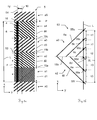
- Fig. 2a shows purely schematically a portion of a system according to the invention 1 for determining positions along a feed direction F. Shown are in plan view, ie along the x-axis, a section of an inventive first 2D pattern 5 of pattern elements 6 and schematically (indicated by one of a dotted line formed rectangle) a first line sensor 4 for scanning the first 2D pattern 5. The first 2D pattern 5 and the first line sensor 4 are located relative to the feed direction F along the measuring section M in a position P relative to each other.
- the longitudinal axis 54 of the first line sensor 4 is aligned in the feed direction F and in a plane parallel to the pattern xy plane, ideally, the longitudinal axis 54 thus runs exactly in the x-direction, with manufacturing tolerances and other deviations thereof, resulting for example during use, with below the terms “parallel” or "outstretched in x-direction” fall. Accordingly, the first 2D pattern 5 can be made very narrow (width in the y-direction), comparatively narrower than systems according to the prior art. Such a small extent of the 2D pattern 5 or of the first line sensor 4 and thus of the system 1 transversely to the feed direction F offers advantages in narrow measuring environments or in terms of a compact system structure.
- an arbitrarily selectable reference point 16 is to be set on the scanning length L, which serves as a reference for determining the position P of the scanning head in the feed direction F.
- the center of the scan length L is set as the reference point 16.
- the pattern elements 6 are designed and arranged in such a way that they each form a one-time first code word on a scanning length L, that is to say an unambiguous sequence of digital values.
- the first 2D pattern 5 on similar pattern elements 6, which are defined differently defined by a fixed regularly varying or pseudorandom sequence.
- the pattern elements 6 encode by distinctly distinguishable configuration, for example, in terms of their shape (e.g., width, x-y plane length) and / or their physical sensing properties (e.g., their transparency or reflectivity in an optical operating principle).
- like-shaped pattern elements 6 are arranged to be varied with respect to the feed direction F, so that one-to-one first codewords are formed which encode the positions.
- the first 2D pattern 5 has two mutually symmetrical regions a1 and a2 with an axis of symmetry 13 which extends in the feed direction F.
- the first 2D pattern 5 thus forms by the design and / or arrangement of Pattern elements 6 with respect to the feed direction F an absolute position code track, for example, from a pseudo random code (PRC) or according to a maximum sequence (Maximum Length Sequence MLS) in binary or higher-order coding.
- PRC pseudo random code
- Maximum Length Sequence MLS maximum Length Sequence
- the resolution of the position determination ie the number of determinable positions on the measuring section, is adjustable by the number of first codewords in the feed direction on the measuring section M, which in turn by the design and / or arrangement of the pattern elements 6 in coordination with the first line sensor used 4 is adjustable.
- the first line sensor 4 scans the first 2D pattern 5 with its detectors 34 arranged within the scanning length L, from which it generates a scanning signal in the form of a sequence of digital values which corresponds to the first code word formed by the sampled pattern elements 6.
- the system 1 operates in the example with a capacitive action principle, for which the - schematically illustrated - pattern elements 6 and the detectors 34 of the first line sensor 4 are formed as electrodes.
- the pattern electrodes 6 and sensor electrodes 34 are capacitively coupled together.
- the capacitive coupling is dependent on the relative position of the first line sensor 4 to the first 2D pattern 5, so that in the respective relative position on a scan length L in each case by the capacitively coupled to the detector electrodes 34 pattern electrodes 6 a one-time first code word is formed.
- the pattern elements. 6 preferably formed from the position along the measuring path dependent light-dark sequence of the signals to be detected on a scan length L.
- This light-dark sequence forms a first codeword, each of which uniquely and absolutely codes a position to be determined.
- the scanning signal of the first line sensor 4 is decoded by the control and evaluation unit 2 and from this the desired position P is determined absolutely, for which purpose a decoding table is stored in the control and evaluation unit 2, by means of which an absolute position P can be assigned to each scanning signal. In other words, from a finite set of absolute, discrete positions P stored in the control and evaluation unit 2, the one associated with the sequence of digital values represented by the scanning signal is selected, this assignment being unambiguous.
- the assignment is preferably created by a calibration run in which absolute positions are assigned to the scanning signals corresponding to the first code words on the basis of a calibration measure.
- the first 2D pattern 5 is designed in such a way that a scanning signal corresponding to a first code word can be generated and thus the desired position P can be determined along the measuring path M if a deviation of the scanning head from its ideal position is present. In addition, based on the 2D pattern, the deviation from the Ideal situation self-determinable.
- the first line sensor 4 and the 2D pattern 5 are then in an ideal position to each other, if no lateral offset .DELTA.y is present - in the illustrated example, the longitudinal axis 54 of the line sensor 4 coincides with the axis of symmetry 13 of the pattern 5, or in other words no displacement exists in the y-direction - if further there is no rotation about the z-axis (ie the longitudinal axis 54 of the line sensor 4 is parallel to the x-axis - counterexample cf. Fig. 4a ), there is no tilt about the y-axis (ie, the first line sensor 4 is not rotated from the 0 ° position about the y-axis - Gegenbeispiel vgl. Fig.
- the first line sensor 4 and 2D pattern 5 then remain in an ideal position relative to one another when the first line sensor 4 and the first 2D pattern 5 are arranged in a well-defined and known starting position and starting orientation relative to each other and no other than the desired translation in the feed direction F. Movement is or has taken place.
- the pattern elements 6 follow Fig. 2a Sections, which are arranged inclined to the feed direction F in the pattern plane xy. Determining a position P according to the invention and one or more of said deviations from the ideal position will be described in more detail with reference to the following figures.
- Fig. 2b shows a portion of another embodiment of the inventive system 1. Shown are schematically the first line sensor 4 and a section of a first 2D pattern 5 in plan view.
- the line sensor 4 is as in the embodiment according to Fig. 2a aligned with its longitudinal axis 54 approximately along the feed direction F.
- the reference point 16 on the first line sensor 4 for determining the position of the scanning head is defined in the example as the end or the beginning of the scanning length L.
- the pattern elements 6 are arranged differently in such a way that they form a one-to-one codeword on a scanning length L and the first 2D pattern 5 in the feed direction F can be divided into a plurality of regions a1, a2, a3, a4, Pattern elements 6 is articulated.
- the different arrangement of the pattern elements 6 by variation of the orientation (inclination to the x-direction) of the pattern elements 6, or the pattern element periodicity, ie number of scannable property changes (eg opaque opaque transparent in optical operating principle) on a Meßordern sau causes.
- the first 2D pattern has a plurality of contiguous distinguishable regions a1-ai.
- regions a1-ai can be produced by differently different arrangements and / or different design of the pattern elements 6. Areas with different arrangement and / or different design of the pattern elements 6 form different area types, so that the first 2D pattern has a defined number of mutually different area types. Equally formed regions a1-ai are referred to as the same region type and may also occur multiple times on the first 2D pattern 5. In the present simple example, the pattern has three types of regions, are shown for example in the areas a0, a3 and a5 (type 1), a1 (type 2) and a2 and a4 (type 3).
- the area boundaries 15a-15i extend according to the arrangement of the pattern elements 6 in the y direction, i. ideally orthogonal to the feed direction F.
- the distance of the region boundaries 15a-15i is referred to as region length d1-di.
- Sampling length L and the range lengths d1-di are selected in such a coordinated manner that in each relative position from the first line sensor 4 to the first 2D pattern 5 at least one, in the example at least three, area boundaries 15a-15i within the scan length L.
- Such a configuration of the first 2D pattern allows first codewords to be formed relatively easily with the aid of the resulting regions a1-ai, by forming first codewords from each one-to-one series of region types for each position along the measurement path M.
- the range lengths d1-di defined as the distance of two range boundaries 15a-15i to each other in the feed direction F, are, as in FIG Fig. 2b shown, optionally different, even for the same area types.
- the different range lengths d1-di are then used to form first codewords by forming the first codewords from a unique combination of range lengths d1-di and sequence of range types, as illustrated by the example below: In the example shown, the first one 2D pattern 5 of three area types built with four different area lengths d1-d4.
- the number of different range lengths d1-di (here: four) and the number of range types (here: three) are matched to one another, preferably to one another relatively prime (co-prime), chosen to obtain the largest possible number of one-to-one combinations and thus one-to-one first codewords.
- There are 3 3 27 different combinations of three consecutive area types.
- the sequences of the range types and range lengths d1-di or their different combinations are stored in the decoding table of the control and evaluation unit 2, so that in each case a position P can be assigned to the scanning signals corresponding to a respective first code word.
- 432 different first codewords L 432 different positions are absolutely encoded with a correspondingly matched scan length L.
- a (average) range length d1-d4 of, for example, 2 mm relative positions of the first line sensor 4 to the first 2D pattern 5 along a measurement distance of 86.4 cm in the feed direction F can be determined absolutely.
- the maximum number of code words that can be formed is adjustable by selecting the scanning length L or, conversely, the (average) area length di, the number of area types and the number of area lengths di. Longer measuring distances can be achieved, for example, by a first 2D pattern 5 having more than three area types ai and / or more than four area lengths d1-d4 and a correspondingly adapted scanning length L.
- the first codewords thus formed by the pattern elements 6 are, therefore, for a comparatively robust scannable or error-free by the totality of Detectors into the corresponding scanning signals convertible, because the determination of the area types based on the properties of the forming pattern elements such as the pattern element periodicities and / or pattern element inclinations redundant on the basis of several pattern elements (or sections of the digital sequence formed by these pattern elements) can take place.
- the range lengths d1-di can be selected with such great differences from one another that the tolerances in determining the range lengths d1-di on the basis of the scanning signal are large.
- the range length di can also be determined with readout inaccuracies or smaller read errors, as a result of which a relatively robustly decodable absolute coding is achieved.
- Fig. 2c schematically shows further developments of a system according to the invention, in which the first scanning head 51 in addition to the first line sensor 4, a second line sensor 4a (shown in phantom in 3 different layers L1, L2 and L3 relative to the first line sensor 4), which also approximately in the feed direction F in the aligned to the pattern plane xy parallel plane, so that the longitudinal axes 54 and 54a of both line sensors 4 and 4a are arranged approximately parallel to each other.
- a second line sensor 4a shown in phantom in 3 different layers L1, L2 and L3 relative to the first line sensor 4
- the two line sensors 4 and 4a are mounted one behind the other in the scanning direction (L1) with respect to the feed direction F, so that the two line sensors 4 and 4a in the feed direction F have a fixed line sensor distance D1 as a distance between the two line sensor centers 14 and 14 'to each other , which is known and stored in the control and evaluation unit.
- the two line sensors 4 and 4a have a fixed line sensor distance D2 in the y direction, ie are arranged next to one another in the feed direction F (L2) or they are arranged offset parallel to one another (L3) with a fixed line sensor distance D3.
- the second line sensor 4a corresponds in its mode of operation to the first line sensor 4 and can be of identical design, ie it is designed to scan the first 2D pattern 5 and to generate a scanning signal which is scanned by the line sensor 4a detected by the second line sensor 4a
- Pattern element 6 formed first codeword corresponds, wherein based on the scanning signal coded by the sampled first codeword position and a deviation of the second line sensor 4a from its ideal position to the first 2D pattern 5 can be determined.
- Fig. 3a shows the same embodiment of a system according to the invention as the Fig. 2b , In the example below Fig. 3a
- the position of the first line sensor 4 and the first 2D pattern 5 deviates by the lateral displacement .DELTA.y from the ideal position (line 10) with respect to the degree of freedom of movement in the y-direction, so that the longitudinal axis 54 of the first line sensor 4 by .DELTA.y in negative y-direction is offset.
- Fig. 3b displays the section 53 of the first 2D pattern 5 Fig. 3a
- the section 53 shows parts of the area a2 with the pattern elements 6d-6f and the area a3 with the pattern elements 6a-6c and the area boundary 15b therebetween.
- the pattern elements 6a-6f are scanned on a portion ⁇ L of the scan length L at locations 55a-55f. Due to the arrangement or orientation of the pattern elements 6a-6f, the position of the scanning points 55a-55f within the scanning length L is dependent on the lateral offset ⁇ y, ie the first line sensor 4 becomes at the same position P in the y-direction relative to the first 2D pattern 5, the sample spots 55a-55f "wander" on the sensor array 24 along the x direction.
- the lateral offset ⁇ y can be determined .
- the scanning signal corresponding to the first code word is evaluated by the control and evaluation unit 2 on the basis of information stored there.
- a Information about the scanning signal stored in the ideal position for example, about the distribution or the strength of the individual signals or groups of signals of the detectors of the first line sensor 4.
- the actually generated and corresponding to the first code word scanning signal in this position P is with this "ideal" Scanning signal compared, for which the corresponding "ideal" scanning signal is looked up based on the first code word.
- the lateral offset ⁇ y is determined on the basis of the stored information.
- the offset ⁇ y is determined on the basis of, for example, the signals of those detectors which scan the first codeword forming pattern elements 6 to scan length L (ie those detectors corresponding to the scan locations 55a-55f) ,
- the pattern elements 6a-6f in the ideal position (line 10) are scanned by the detectors with the placement a, a + 3, a + 6, a + 8, a + 10, and a + 12 in the linear array (a: any natural Number).
- the lateral array is stored thereon on the basis of the information stored in the control and evaluation unit 2 Offset ⁇ y calculated or looked up by means of a table created in a calibration process.
- the pattern elements 6 form on the entire length in the y-direction of the first 2D pattern 5 in each case on a scanning length L a first codeword which not only encodes the position P but also the offset ⁇ y.
- the determination of the lateral offset .DELTA.y is further illustrated by the following example:
- the distances are determined by forming the difference of the placements of the detectors detecting the pattern elements 6a-6f, this difference corresponding to the difference of the digital values associated with the centroids of the sampled pattern elements 6a-6f.
- the digital values 28, 18, 8 are assigned to the pattern elements 6a-6c or to the region a3 on the basis of the information stored in the control and evaluation unit 2, that is to say the equations (1), (2) and the determined distances ⁇ 1, ⁇ 2, ⁇ 3 , the values -1, -14, -27 are assigned to the pattern elements 6d-6f and the region a2, respectively.
- the pattern elements 6 of a region have different inclinations and / or varying distances to each other.
- the pattern elements 6 have no straight, but a tortuous or curved and / or discontinuous, discontinuous course, which is known by calculation or calibration and stored in table or function in the control and evaluation unit 2.
- Fig. 4a provides in oversight compared to Fig. 2b a rotation of the first line sensor 4 about the z-axis.
- the first line sensor 4 is rotated about its center 14 by the rotational angle ⁇ from its ideal position (line 10).
- the scanning signal or the first code word which encodes the position P is stored as a function of the rotation angle ⁇ in the control and evaluation unit.
- the functional dependence of the scanning signal on the angle of rotation ⁇ is stored as a calculation rule or table for reference in the control and evaluation unit.
- Either one functional dependency per codeword or per group of codewords is used or, given the occurrence of only relatively small deviations from the ideal position, a single functional dependency for all codewords is used.
- the calculation rule or table is calculated, if appropriate for each scanning signal or each first code word, from knowledge of the entire first 2D pattern 5 or determined in a calibration run. On the basis of the functional relationship thus determined, the position P and the angle of rotation ⁇ are determined in the position P from the scanning signal in the rotated orientation of the first line sensor 4.
- Fig. 4b represents a tilting of the first line sensor 4 about the x-axis from the ideal position (line 9). Shown is a frontal view (x-axis orthogonal to the drawing plane).
- the first line sensor 4 whose longitudinal axis extends orthogonal to the plane of the drawing, is tilted from its ideal position (line 9) by the x-tilt angle ⁇ , or in other words is rotated about the x-axis by the x-tilt angle ⁇ .
- the determination of the position P and the tilting or the x-tilt angle ⁇ are carried out analogously to the procedure according to FIG Fig.
- the scanning signal or the first code word which codes the position is stored as a function of the x-tilt angle ⁇ in the control and evaluation unit 2 in the form of a calculation rule or table.
- the functional dependence is also determined as described above per scanning signal or for several or all scanning signals, namely mathematically or by means of a calibration run.
- the signal amplitude of the respective detector signal of the individual detectors is taken into account when creating the functional relationship between scanning signal and x-tilt angle ⁇ , if the strength or amplitude of the detector signal of a detector from its distance from the first 2D pattern due to the applied physical principle for scanning 5 (unique and detectable) is dependent.
- the position and the x-tilt angle ⁇ are determined in the position P from the scanning signal in the tilted orientation of the first line sensor 4.
- FIG. 3 illustrates a tilting of the first line sensor 4 about the y-axis from the ideal position (line 12) in side view, with the longitudinal axis 54 of the first line sensor 4 in the ideal position (line 12) in the x-direction parallel to the plane of the first 2D pattern 5 runs.
- the determination of the position P and the tilting or the y-tilt angle ⁇ take place analogously to the procedure according to FIG Fig. 4a and 4b .
- Optional will be included analogous to the procedure according to Fig. 4b when creating the functional relationship between the scanning signal and the y-tilt angle ⁇ , the signal amplitude of the respective detector signal of the individual detectors is taken into account.
- the width of a respective pattern element 6 formed by a detector is compared with the stored width in an ideal position (line 12), from which the distance in the z direction of the respective detector to the first 2D pattern 5 is concluded becomes.
- a capacitive measuring principle the distance dependence of the capacitance formed by the pattern electrodes and sensor electrodes is used.
- Such an approach taking into account the signal amplitude of the respective detector signal of the individual detectors is optionally also used to additionally or alternatively as a further deviation from the ideal position, the offset in the z-direction of the first line sensor 4, ie the distance of the first line sensor 4 to the first 2D Pattern 5 as the distance of its sensor center 14 to the first 2D pattern 5 to determine.
- FIGS. 5a and 5b show a development of a system according to the invention 1, in which the first scanning head 51 next to a first approximately orthogonal to the feed direction F aligned line sensor 4 has a second also approximately orthogonal to the feed direction F aligned line sensor 4a.
- the Fig. 5a shows a schematic representation in side view of the system 1 with pattern carrier 50, which has the first 2D pattern 5 with pattern elements 6, and with the first scanning head 51, which the control and evaluation unit 2 and the two line sensors 4 and 4a in an ideal position relative to first 2D pattern 5 has.
- the two line sensors 4 and 4a are aligned approximately parallel to one another and mounted one behind the other in the first scanning head 51 in the feed direction F, which is why they have a fixed line sensor distance D as the distance of the two line sensor centers 14 and 14 'from one another.
- the first and the second line sensor 4 and 4a are arranged with a fixed line sensor distance in the feed direction F next to each other or in parallel offset from each other (analogous to the representation according to FIG Fig. 2c ).
- the line sensor distance D is known and stored in the control and evaluation unit 2.
- the second line sensor 4a like the first line sensor 4, is designed to scan the first 2D pattern 5 and to generate a scanning signal which corresponds to the first code word formed by the pattern elements 6 respectively scanned by the second line sensor 4a.
- the absolute position coded by the sampled first code word and a deviation from the ideal position of the second line sensor 4a with respect to the first 2D pattern 5 can be determined based on the first code word on the basis of the scanning signal.
- the position to be determined as the position of the first scanning head 51 is determined in the presence of two spaced apart in the feed direction F line sensors 4, 4a.
- Fig. 5b shows in plan a partial area of the inventive system 1 Fig. 5a ,
- the first 2D pattern 5 which is scanned by the first line sensor 4 and the second line sensor 4a, which are integrated in the indicated first scanning 51.
- the first and second line sensors 4 and 4a have the same scanning length L. Alternatively, the scan lengths are different in size.
- the first 2D pattern 5 has pattern elements 6, which are designed as straight lines of different width and complementary physical property (in the optical case, opaque / transparent, reflective / non-reflective). They form first codewords by a fixed regularly varying or pseudo-random, defined different sequence and defined distinguishable embodiment (in the example, the different width).
- the pattern elements 6 are not configured as straight, but as curved lines, as shown, optionally varying the width and / or physical property of a pattern element 6 continuously.
- the first scanning head 51 and thus the two line sensors 4 and 4a are not in an ideal position (line 10) relative to the first 2D pattern 5, but the first scanning head 51 is offset by the amount ⁇ ya in the positive y-direction and around the z Axis rotated by the rotation angle ⁇ .
- the pattern elements 6 are aligned inclined and separated into two groups of pattern elements 6 different inclination that a v-shaped first 2D pattern 5 is formed with an axis of symmetry 13 as the area boundary 15 between a first area a1 (shown on the left) with pattern elements 6 of the first slope and a second area a2 (shown on the right) with pattern elements 6 of the second inclination.
- a respective first code word is formed on the basis of pattern elements 6 from both regions a1 and a2, ie for generating a first signal word corresponding to a sample signal respectively pattern elements 6 of the first (left) area a1 and pattern elements 6 of the second (right) area a2 of a respective line sensor 4 and 4a is scanned.
- pattern elements 6 form symmetrically about the symmetry axis 13 of the first 2D pattern 5 a first codeword on ay length that is smaller than the scan length L of FIG Line sensors 4 and 4a, so that even with a sample in a lateral offset ⁇ ya always a corresponding to the first code word scanning signal is generated.
- the y-length of the first code word is tuned to a maximum possible lateral offset ⁇ ya max .
- the pattern elements 6 form on the entire extent of the first 2D pattern 5 in the y-direction in each case on a scanning length L, a first code word, which individually encodes the position P to be determined.
- the same first code word or different first code words whose corresponding scanning signals are all assigned to the same position P are in each case the same first code word or different first code words whose corresponding scanning signals are all assigned to the same position P.
- the scanning signal or the first code word which encodes position P is stored as a function of the angle of rotation (here: ⁇ ) in the control and evaluation unit as a calculation rule or table for reference ( see description to Fig. 3a ).
- the deviation (s) of the first scanning head 51 is determined from the ideal position of the first line sensor 4 and the second line sensor 4a and the known line sensor distance D based on the respective deviation (s).
- the first scanning head 51 deviates from an ideal position (line 10) in that it is rotated by the angle ⁇ both around the scanning head center 57 with respect to the z-axis and the scanning head center 57 laterally (in the y direction) an amount ⁇ ya is offset.
- the rotation or the angle of rotation ⁇ and the lateral offset ⁇ ya are determined on the basis of the respective lateral offset of the first and second line sensors 4 and 4a with knowledge of the line sensor distance D.
- the angle of rotation ⁇ is determined based on the rotation of the first and / or second line sensor 4 or 4a about the z-axis. Accordingly, a rotation about the x-axis or a tilting ie rotation about the y-axis of the first scanning head 51 are determined on the basis of the tilting or rotation about the x-axis of the two line sensors 4 and 4a.
- the deviations from an ideal position of the first or second line sensor 4 or 4a relative to the first 2D pattern is carried out analogously to the descriptions of the FIGS. 3a-4c ,
- deviations of the first scanning head 51 from a well-defined position and orientation relative to the first 2D pattern 5 can be determined even more accurately than with only a first line sensor 4, wherein for highly accurate applications deviations of the first scanning head 51 of a Ideal position can be determined by the use of two line sensors 4 and 4a with respect to all degrees of freedom of movement.
- the also to be determined absolute position of the first Scanning head 51 for example, as the position of the Abtastkopfmitte 57 relative to the first 2D pattern is formed, for example as an average of the two absolute positions of the two line sensors 4 and 4a, which offers advantages in the accuracy of determining the position of the first scanning 51.
- the use of two line sensors 4 and 4a is also advantageous in terms of the robustness of the position determination.
- Systems 1 according to the invention are particularly suitable for measuring devices 60, such as absolute linear encoders or linear displacement encoders, in which the position of members movable along a measuring path relative to one another is to be determined.
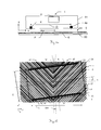
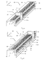
- Fig. 6a shows a schematic representation in perspective view of a development of such a measuring device 60.
- the measuring device 60 comprises a first inventive system 1 having a first scanning head 51 and a first 2D pattern 5 and a second inventive system 1a with a second scanning head 51a and a second 2D Pattern 5a on.
- the first 2D pattern 5 and the second 2D pattern 5a are applied to a common three-dimensional pattern carrier 50.
- the two scanning heads 51 and 51a each have at least one line sensor for scanning the respective 2D pattern.
- the two scanning heads 51 and 51a and the control and evaluation unit 2 are integrated as a common control and evaluation unit for both systems 1 and 1a in an object 52 whose position P in the feed direction F along the measuring section M is to be determined, the two Scanning heads 51 and 51a have a fixed and known spatial arrangement in the object and thus to each other.
- the properties of the second 2D pattern 5a and of the second scanning head 51a according to the invention correspond to those of the first 2D pattern 5 and the first scanning head 51, so that a position P can be determined absolutely on the basis of the 2D patterns 5 and 5a and a deviation from one Ideal position of the one or more line sensors and thus by the respective scanning 51 and 51a and the object 52 relative to the respective 2D pattern 5 and 5a can be determined.
- the 3D pattern carrier 50 has at least three sides, the edges of which are parallel to one another, so that the 3D pattern carrier corresponds to a straight prism having a triangular or otherwise polygonal cross section (in FIG Fig.
- the first and the second 2D patterns 5 and 5a lie in two different, non-parallel planes and extend parallel to one another in the feed direction, so that the second 2D pattern 5a is at an angle ⁇ to the first in the zy plane 2D pattern 5 is arranged.
- the arrangement of the first 2D patterns 5 and 5a is selected such that the first 2D pattern 5 lies in an xy plane and the second 2D pattern 5a in a zx plane.
- the two pattern planes intersect at an angle ⁇ of 90 °. It has been found that good results with an angle in the range of about 20 ° ⁇ ⁇ 120 ° can be achieved.
- first and second 2D pattern 5 and 5a Due to the inventive properties of the first and second 2D pattern 5 and 5a and their different orientation in space and the fixed and known spatial arrangement of line sensors or scanning heads 51 and 51a relative to the object 52, the position of the object 52 and a deviation from one Ideal position of the object 52 relative to the pattern carrier 50 with respect to all degrees of freedom of movement determinable.
- a lateral offset in the y direction is determined on the basis of the first 2D pattern 5, and a lateral offset in the z direction based on the second 2D pattern 5a, so that a total offset of the object 52 in the yz plane, ie transversely to the Feed direction F, is determined.
- twists and tilt of the object 52 are determined from the rotations or tiltings of the first scanhead 51 and the second scanhead 51a.
- Fig. 6b shows an alternative advantageous use of an inventive measuring device 60, which has two inventive systems 1 and 1a, with respect to a position determination along a measuring section M.
- Shown is a schematic perspective view of a 3D pattern carrier 50 with two mutually perpendicular side surfaces extending in the feed direction F extend, wherein the one side surface patterned measuring sections M1 with two first 2D patterns 5, 5 'according to the invention and the other side face having patterned measuring sections M2 with three second 2D patterns 5a, 5a' and 5a "according to the invention on which the relative position of the object 52, hereinafter referred to as measuring path position PM, is to be determined.
- the first 2D patterns 5 and 5 ' are arranged one behind the other in the feed direction F and are identical to one another.
- the first and second 2D patterns 5, 5 'and 5a-5a" extend in the feed direction F parallel to each other, so that along the measuring section M in each case a first 2D pattern 5 or 5 'from the first scanning head 51 of the first system 1 and at the same time a second 2D pattern 5a, 5a' or 5a "from the second scanning head 51a of the second system 1a
- each first 2D pattern 5, 5 ' respectively forms first code words
- each second 2D pattern respectively second code words, which positions on the length M1 or M2 of the respective pattern 5, 5' and 5a-5a "absolute and clearly encode.
- first 2D patterns 5 and 5 'and the second 2D patterns 5a-5a are identical to one another, the respective first and second code words occur twice (first 2D pattern) or three times (second 2D) on the entire measurement path M, respectively
- the pattern lengths M1 and M2 are now selected to be so different and coordinated with one another that along the entire measuring path M when scanning a first pattern 5 or 5 '. and a second pattern 5a-5a "in the same relative position of object 52 to pattern carrier 50 a codeword combination as a combination of a first codeword of the first pattern 5 or 5 'and a second codeword of the second pattern 5a, 5a', 5a" occurs only once.
- the absolute determination of the measurement path position PM is based on the codeword combination of first and second codeword by means of stored in the control and evaluation unit 2 information such as an assignment table from Meßumblenpositionen PM and codeword combinations PM and combinations of the scanning signals respectively corresponding to the first and second codewords or an allocation table of measuring path positions PM and the combinations of the positions respectively associated with the first codeword and the second codeword.
- Fig. 6b shows the better overview because of very different lengths first and second 2D patterns.
- the difference between the pattern length M1 of the first 2D pattern 5 or the difference between the number of first code words as small as possible and the pattern length M2 or the number of second code words of the second 2D pattern 5a minimal and the pattern lengths M1, M2 the codeword numbers are divisive to one another, which advantageously results in the largest possible number of encodable meter path positions PM.
- the first 2D pattern 5 on the pattern length M1 has 1024 first codewords and the second 2D pattern 5a on the pattern length M2 1023 has second codewords.
- the measuring section M can be divided into 1047552 determinable positions. Corresponding to each of the encoded discrete positions a measuring section piece of, for example 100 ⁇ m, this results in a measuring path M of at 104,7552m pattern lengths M1 and M2 of 10,24cm or 10,23cm.
- Such a measuring device 60 is above all advantageous in the case of long measuring sections M, ie in the case of a long-stroke measuring device 60, since less complex codewords are necessary for 2D patterns which absolutely code positions on a length M1 or M2 than in a single one Absolute coding, which must provide a univocal first or second code words for the entire measuring path M.
- smaller pattern lengths M1, M2 offer advantages with regard to the production, transport and / or assembly of the pattern. For example, instead of on a common, long pattern carrier 50, as in Fig.
- the first 2D patterns 5, 5 ' are applied on separate, short pattern carriers which are mounted one after the other on one side of the measuring device 60 in the feed direction and likewise the second 2D patterns 5a-5a "are applied on further separate, short pattern carriers, which are mounted one after the other on the measuring device in the feed direction next to the pattern carriers of the first 2D patterns 5, 5 ', optionally on another side of the measuring device 60.
- the first 2D patterns 5, 5' extend on one side as in the case of attachment common 3D pattern carrier 50 parallel to the second 2D patterns 5a-5a ".
- the first 2D pattern 5 and the second 2D pattern 5a differ somewhat more than just one code word. For example, if ten pattern carrier with first 2D patterns 5 and parallel to these pattern carriers in accordance ten pattern carrier with second 2D patterns consecutively mounted 5a in the feed direction F, each with an accuracy of 100 ⁇ m, is formed overall in the feed direction F, an inaccuracy of 1 mm.
- the second 2D pattern 5a with a first 2D pattern 5 with 1024 codewords 1024-11 1013 code words instead of 1023 codewords.
- a respective scanning head 51 or 51a for increasing the robustness of the system 1, 1a or the measuring device 60 has at least one further line sensor, that is, at least two or three line sensors.
- Fig. 7 shows an inventive measuring device 60, which is designed as a coordinate measuring machine (CMM).
- the CMM 60 is designed to determine the position of an optical or tactile scanning tip 27 in space. It has a plate-like base 21, which spans an xy plane and on which a portal 23 with two gantry beams 20 is arranged such that the gantry is movable relative to the base 21 in the x-direction.
- the portal 23 further comprises a bridge 22 and a Z-pillar 26, wherein the gantry beams 20 are connected to each other at their base remote ends via the bridge 22.
- a carriage 25 is arranged, which is relative to the bridge 22 in Y-direction is movable.
- the Z-pillar 26 is movable relative to the carriage 25 in the z-direction, is guided in a receptacle of the carriage 25 and has at its base 21 facing the end of the scanning 27 on.
- the direction of the respective relative movement of the portal 23, slide 25 and Z-pillar 26 respectively defines a feed direction Fx, Fy, Fz along at least one, in the example two systems according to the invention 1x and 1x ', 1y and 1y', 1z and 1z 'a position (of the portal relative to the base, the carriage opposite the bridge, the z-pillar opposite the carriage) can be determined.
- the 1x or 1x 'systems are integrated into the CMM 60 such that the base 21 has the first 2D pattern 5x and the second 2D pattern 5x' and the gantry 23 the first and second scanheads, respectively, for scanning the 2D Patterns 5x and 5x ', respectively.
- the further systems 1y or 1y 'and 1z or 1z' are integrated into the CMM 60 such that their scanning heads with the carriage 25 relative to the applied on the bridge 22 and the Z-pillar 2D patterns 5y / 5y 'or 5z / 5z' are movable.
- 2D patterns 5x-5z ' each of which covers the entire possible measuring path in the x, y or z direction
- 2D patterns 5 of smaller pattern length, arranged one behind the other, are used in each feed direction Fx, Fy, Fz.
- So systems 1x-1z ' analogous to those in Fig. 6b are formed shown. From the positions PX, PY and PZ determined according to the invention and deviations from the ideal positions of the scanning heads 51x-51z ', the spatial position of the scanning tip 27 can be determined absolutely and with high precision.
- the present invention thus makes it possible by the absolute position and deviation determination even without high-precision design or manufacture of the CMM 60 and / or without complex high-precision methods for calibrating the CMM 60 to determine the spatial position of the scanning tip 27 high-precision.
- the spatial position of the scanning tip 27 can be determined even more precisely with such a design or calibration effort than with measuring devices according to the prior art by the absolute position and deviation determination according to the invention.
Landscapes
- Physics & Mathematics (AREA)
- General Physics & Mathematics (AREA)
- Engineering & Computer Science (AREA)
- Signal Processing (AREA)
- Transmission And Conversion Of Sensor Element Output (AREA)
- Length Measuring Devices With Unspecified Measuring Means (AREA)
- Length Measuring Devices By Optical Means (AREA)
Abstract
System (1) zur Bestimmung von Positionen entlang einer Vorschubrichtung mit einem ersten Sensor (4), insbesondere einem Zeilensensor, mit einer Abtastlänge (L) zum Abtasten eines ersten 2D-Musters (5, 5') und Erzeugen eines Abtastsignals. Das erste 2D-Muster (5, 5') weist Musterelemente (6) auf, welche jeweils auf wenigstens einem Teil der Abtastlänge (L) ein erstes Codewort bilden, das eine Position entlang der Vorschubrichtung absolut codiert. Zudem ist basierend auf dem ersten Codewort eine Abweichung von einer Ideallage (9, 10, 12) des ersten Sensors (4) zum ersten 2D-Muster (5) bestimmbar.System (1) for determining positions along a feed direction with a first sensor (4), in particular a line sensor, with a scanning length (L) for scanning a first 2D pattern (5, 5 ') and generating a scanning signal. The first 2D pattern (5, 5 ') has pattern elements (6), which in each case form a first code word on at least part of the scan length (L) which absolutely codes a position along the feed direction. In addition, based on the first code word, a deviation from an ideal position (9, 10, 12) of the first sensor (4) to the first 2D pattern (5) can be determined.
Description
Die Erfindung betrifft ein System zur Bestimmung von Positionen entlang einer Vorschubrichtung mit einem Sensor zum Abtasten eines Musters und einem abtastbaren 2D-Muster nach Anspruch 1 sowie ein Verfahren zum Bestimmen von Positionen entlang einer Vorschubrichtung nach Anspruch 12 und ein ebensolches Computerprogrammprodukt.The invention relates to a system for determining positions along a feed direction with a sensor for scanning a pattern and a scannable 2D pattern according to
Systeme zur Bestimmung von Positionen entlang einer Vorschubrichtung sind in vielen Anwendungsbereichen gefordert, in denen die Position eines entlang einer Vorschubrichtung beweglichen Objekts zu bestimmen ist, z.B. die Stellung einer Maschinenkomponente auf einer linearen Achse wie Antriebe oder Schwenkarme. Die dabei erfassten Stellungen können als Positionswerte zu Vermessungszwecken genutzt werden, oder auch für eine Positionierung von Komponenten durch einen Antrieb mit Positionsregelkreis. Solche Positionsbestimmungssysteme finden sich entsprechend in Geräten wie Koordinatenmessmaschinen (CMM), geodätischen Geräten, Roboterarmen oder hydraulischen Aktuatoren. Ein solches System weist in der Regel ein Muster und einen Sensor auf, wobei entweder das Muster oder der Sensor mit dem beweglichen Objekt verbunden ist und Muster und Sensor entlang der Vorschubrichtung relativ zueinander beweglich sind. Der Sensor tastet das Muster ab und erzeugt ein vom abgetasteten Musterabschnitt abhängiges Abtastsignal. Das Muster ist so strukturiert, dass das Abtastsignal sich mit einer Änderung der Relativlage des Sensors zum Muster und damit der zu bestimmenden Position des Objekts ändert. Eine Steuer- und Auswerteeinheit des Systems ermittelt aus dem Abtastsignal anhand hinterlegter Information über das Muster die gesuchte Position. Beispielsweise weist das Muster für eine inkrementelle Positionsbestimmung gleichartige Musterelemente auf, welche mit jeweils gleichem Abstand zueinander in Vorschubrichtung angeordnet sind. Der Sensor tastet jeweils ein Musterelement ab. Als Information ist in der Steuer- und Auswerteeinheit der Abstand der Musterelemente hinterlegt, so dass, ausgehend von einer definierten Nullstellung von Sensor und Muster, aus der Zahl der bei einer Relativbewegung von Sensor und Muster abgetasteten gleichartigen Abtastsignale die Position bestimmbar ist. Nachteilig an Systemen mit inkrementeller Positionsbestimmung ist, dass bei einem Neustart des Systems jedes Mal wieder von einer Null- bzw. Referenzstellung ausgegangen werden muss.Systems for determining positions along a feed direction are required in many applications in which the position of an object to be moved along a feed direction is to be determined, eg the position of a machine component on a linear axis such as drives or pivot arms. The positions detected in this case can be used as position values for surveying purposes or else for positioning of components by a drive with position control loop. Such positioning systems can be found in devices such as CMM (coordinate measuring machines), geodetic devices, robot arms or hydraulic actuators. Such a system typically includes a pattern and a sensor with either the pattern or sensor connected to the moveable object and the pattern and sensor movable relative to each other along the direction of advance. The sensor samples the pattern and generates a sample signal dependent on the sampled pattern portion. The pattern is structured so that the scanning signal changes with a change in the relative position of the sensor to the pattern and thus the position of the object to be determined. A control and evaluation unit of the system determines the sought position from the scanning signal based on stored information about the pattern. For example, the pattern for an incremental position determination similar pattern elements, which are each arranged with the same distance from each other in the feed direction. The sensor scans a pattern element. As information, the distance of the pattern elements is stored in the control and evaluation unit, so that, starting from a defined zero position of sensor and pattern, from the number of sampled in a relative movement of the sensor and pattern similar scanning the position can be determined. A disadvantage of systems with incremental position determination is that every time a system is restarted, it must again be assumed that there is a zero or reference position.
Dagegen erzeugen bei Systemen mit absoluter Positionsbestimmung jeweils einzelne Musterelemente oder Folgen von Musterelementen eindeutige und unterscheidbare Abtastsignale. Dadurch kann einer jeweiligen Relativlage von Sensor zu Muster unmittelbar, d.h. ohne eine Referenzstellung anzufahren, eine eindeutige Position zugeordnet werden.In contrast, in systems with absolute position determination, individual pattern elements or sequences of pattern elements produce unique and distinguishable scanning signals. Thereby, a respective relative position of sensor to pattern immediately, i. without moving to a reference position, be assigned a unique position.
Idealerweise ändern Sensor und Muster ihre relative Lage zueinander nur in Vorschubrichtung, d.h. ihre Bewegung relativ zueinander weist nur einen Freiheitsgrad (engl.: "degree of freedom", DoF) auf. In der Praxis treten jedoch häufig unerwünschte Abweichungen von dieser Ideallage auf, d.h. die Lage vom Sensor zum Muster variiert unbeabsichtigt oft in wenigstens einer weiteren Raumrichtung d.h. bezüglich wenigstens eines weiteren Bewegungsfreiheitsgrads, z.B. in Form eines Versatzes, einer Verdrehung oder einer Verkippung. Dabei ist der Versatz entweder konstant oder dadurch von der Relativlage abhängig, dass die Vorschubrichtung und Längsachse des Musters nicht exakt parallel zueinander sind. Weiter können Verdrehungen oder Verkippungen des Sensors auftreten, d.h. eine unbeabsichtigte Rotation des Sensors um wenigstens eine seiner Achsen. Derartige Abweichungen von der Ideallage können die Messgenauigkeit beeinträchtigen. Solche Abweichungen möglichst gering zu halten, d.h. die Ideallage möglichst genau einzuhalten, bzw. Abweichungen zu kompensieren erfordert, vor allem bei einem grossen Bewegungsbereich in Vorschubrichtung, einen hohen konstruktiven Aufwand und/oder aufwändige Kalibrierverfahren.Ideally, sensor and pattern change their relative position to one another only in the feed direction, ie their movement relative to one another has only one degree of freedom (DoF). In practice, however, undesirable deviations often occur from this ideal position, ie the position from the sensor to the pattern unintentionally often varies in at least one further spatial direction, ie with respect to at least one further degree of freedom of movement, eg in the form of an offset, a twist or a tilt. The offset is either constant or dependent on the relative position that the feed direction and longitudinal axis of the pattern are not exactly parallel to each other. Next can be twists or Tilting of the sensor occur, ie unintentional rotation of the sensor about at least one of its axes. Such deviations from the ideal position can affect the measurement accuracy. To keep such deviations as low as possible, ie to comply with the ideal situation as accurately as possible, or to compensate deviations requires, especially with a large range of movement in the feed direction, a high design effort and / or complex calibration.
Als Alternative offenbart die
Die
Die Aufgabe der vorliegenden Erfindung besteht daher in der Bereitstellung eines verbesserten Systems zur Bestimmung von Positionen entlang einer Vorschubrichtung, mit welchem sowohl eine Abweichung eines Sensors aus seiner Ideallage zu einem Muster als auch einfach aber präzise die absolute Position bestimmbar sind.The object of the present invention is therefore to provide an improved system for the determination of positions along a feed direction, with which both a deviation of a sensor from its ideal position to a pattern as well as simply but precisely the absolute position can be determined.
Diese Aufgabe wird erfindungsgemäss durch die Merkmale der unabhängigen Ansprüche und/oder durch Merkmale der abhängigen Ansprüche gelöst bzw. diese Lösungen weitergebildet.This object is achieved according to the invention by the features of the independent claims and / or by features of the dependent claims or further developed these solutions.
Die vorliegende Erfindung betrifft ein System zur Bestimmung von Positionen entlang einer Vorschubrichtung. Das System weist ein erstes zweidimensionales Muster (2D-Muster) auf, das sich in Vorschubrichtung erstreckt, und einen in einen ersten Abtastkopf integrierten ersten Sensor mit einem Array von Detektoren zum Abtasten des ersten 2D-Musters und zum Erzeugen eines Abtastsignals. Dabei wird das erste 2D-Muster vom ersten Sensor mit Detektoren eines festgelegten länglichen Abschnitts des Arrays abgetastet. Die Länge dieses Abschnitts ist als Abtastlänge definiert. Die Ausrichtung der Abtastlänge definiert eine Längsachse. Die Abtastlänge entspricht maximal der Ausdehnung des Detektorarrays und ist sehr viel kleiner als die Ausdehnung des ersten 2D-Musters in Vorschubrichtung. Weiter weist das System eine Steuer- und Auswerteeinheit zur Auswertung des Abtastsignals auf. Der erste Sensor und das erste 2D-Muster sind entlang der Vorschubrichtung relativ zueinander beweglich. Das erste 2D-Muster besteht aus Musterelementen und ist dergestalt ausgebildet, dass anhand des ersten 2D-Musters die zu bestimmende Position absolut bestimmbar ist und zudem eine Abweichung von einer Ideallage bezüglich wenigstens eines Bewegungsfreiheitsgrads (neben der Bewegung in Vorschubrichtung) vom ersten Sensor relativ zum ersten 2D-Muster bestimmbar ist. Die Musterelemente bilden dazu jeweils zumindest auf einem Teil der Abtastlänge ein erstes Codewort. Unter Codewörtern werden eindeutig voneinander unterscheidbare Folgen digitaler Werte verstanden. Das erste Codewort codiert jeweils die zu bestimmende Position absolut, so dass das erste 2D-Muster in Vorschubrichtung eine absolute Positionscodespur aus einer Reihe hintereinander angeordneter erster Codewörter bildet. Zudem ist basierend auf dem zu jeder Position gehörenden ersten Codewort die Abweichung von der Ideallage vom ersten Sensor relativ zum ersten 2D-Muster in der jeweiligen Position bestimmbar. Das vom ersten Sensor erzeugte Abtastsignal in der jeweiligen Position korrespondiert mit dem ersten Codewort. In der Steuer- und Auswerteeinheit ist eine Decodierinformation, vorzugsweise eine Decodiertabelle hinterlegt, anhand derer jedem Abtastsignal eindeutig eine absolute Position zuordenbar ist. Weiter sind in der Steuer- und Auswerteeinheit Informationen hinterlegt, anhand derer, basierend auf dem ersten Codewort bzw. dem zugehörigen idealen Abtastsignal, das ermittelte Abtastsignal derart auswertbar ist, dass die Abweichung von der Ideallage vom ersten Sensor zum ersten 2D-Muster zumindest bezüglich eines Bewegungsfreiheitsgrades bestimmbar ist.The present invention relates to a system for determining positions along a feed direction. The system has a first two-dimensional pattern (2D pattern) extending in the feed direction, and a first sensor integrated with a first scanning head having an array of detectors for scanning the first 2D pattern and generating a scanning signal. In this case, the first 2D pattern is scanned by the first sensor with detectors of a fixed elongated section of the array. The length of this section is defined as the scan length. The orientation of the scan length defines a longitudinal axis. The scan length corresponds at most to the extent of the detector array and is much smaller than the extension of the first 2D pattern in the feed direction. Furthermore, the system has a control and evaluation unit for evaluating the scanning signal. The first sensor and the first 2D pattern are movable relative to each other along the feed direction. The first 2D pattern consists of pattern elements and is designed such that on the basis of the first 2D pattern the position to be determined is absolutely determinable and also a deviation from an ideal position with respect to at least one degree of freedom of movement (in addition to the movement in the feed direction) from the first sensor relative to first 2D pattern is determinable. For this purpose, the pattern elements each form a first code word for at least part of the scanning length. Codewords are understood to be uniquely distinguishable sequences of digital values. The first codeword encodes the position to be determined absolutely, so that the first 2D pattern in the feed direction forms an absolute position code track from a series of first codewords arranged one behind the other. In addition, based on the first code word associated with each position, the deviation from the ideal position from the first sensor relative to the first 2D pattern in the respective position can be determined. The scanning signal generated by the first sensor in the respective position corresponds to the first code word. In the tax and Evaluation unit is a decoding information, preferably a decoding table stored, based on which each scanning signal unambiguously an absolute position can be assigned. Furthermore, information is stored in the control and evaluation unit on the basis of which, based on the first code word or the associated ideal scanning signal, the determined scanning signal can be evaluated such that the deviation from the ideal position from the first sensor to the first 2D pattern at least with respect to one Freedom of movement is determinable.
Besonders vorteilhaft hinsichtlich des Kosten-Nutzen-Verhältnisses ist es, als Sensor einen Zeilensensor zu verwenden, d.h. einen Sensor mit einem eindimensionallänglichen, linearen Array von Detektoren. Die folgenden Darstellungen beziehen sich daher beispielhaft auf einen Zeilensensor, wenngleich sich die vorliegende Erfindung nicht auf solche Zeilensensoren beschränkt, sondern auch andere Sensoren, z.B. Mehrzeilensensoren bzw. Sensoren mit einem 2D-Array von Detektoren, mit den oben beschriebenen Merkmalen umfasst.Particularly advantageous in terms of cost-benefit ratio is to use a line sensor as a sensor, i. a sensor with a one-dimensional, linear array of detectors. The following illustrations therefore, by way of example, relate to a line sensor, although the present invention is not limited to such line sensors, but also other sensors, e.g. Multi-line sensors or sensors with a 2D array of detectors, comprising the features described above.
Bevorzugt ist das System zur opto-elektronischen und/oder kapazitiv-elektronischen Mustererkennung bzw. Abtastung des ersten 2D-Musters ausgebildet, wenngleich sich alle physikalischen Wirkprinzipien erfindungsgemäss eignen, die in Systemen zur Bestimmung von Positionen einsetzbar sind. Um zumindest auf einem Teil der Abtastlänge erste Codewörter zu bilden, die die gesuchten Positionen absolut codieren, sind die Musterelemente des ersten 2D-Musters in Vorschubrichtung definiert unterscheidbar ausgestaltet und/oder angeordnet, so dass jeweils durch eine definierte und auf die Abtastlänge abgestimmte Anzahl von Musterelementen eine Folge von digitalen Werten gebildet wird, welche in Vorschubrichtung auf dem gesamten 2D-Muster nur einmal vorkommt. Dadurch ist eine jede Folge eineindeutig und zur absoluten Positionscodierung geeignet. Unterschiedliche Ausgestaltung meint z.B. unterschiedliche Form oder unterschiedliche abtastbare physikalische Eigenschaft der Musterelemente, bei einem optischen ersten 2D-Muster also beispielsweise die Lichtdurchlässigkeit oder das Reflexionsvermögen, unterschiedliche Anordnung meint z.B. unterschiedliche Abfolge oder Neigung der Musterelemente. In jeder Relativlage des ersten Zeilensensors zum ersten 2D-Muster ist jedes Musterelement, das sich, zumindest teilweise, im Bereich der Abtastlänge befindet, von zumindest einem Detektor abtastbar. Dabei ist es nicht wie bei Systemen nach dem Stand der Technik erforderlich, dass eine Kante eines Musterelementes von einem Detektor abtastbar ist. Insofern ist es im Gegensatz zum Stand der Technik nicht nötig die Breite der Musterelemente und die Detektoren des Zeilensensors aufeinander abzustimmen. Bevorzugt ist aber in jeder Relativlage des ersten Zeilensensors zum ersten 2D-Muster von jedem Detektor der Abtastlänge wenigstens ein Musterelement bzw. ein Abschnitt eines Musterelements abtastbar. Die Detektoren auf der Abtastlänge bilden durch Abtasten der ein erstes Codewort codierenden Musterelemente eine Folge elektrischer Signale, wobei dem durch das Abtasten erzeugten Signal jedes Detektors ein digitaler Wert zugeordnet wird. Somit korrespondiert das Abtastsignal jeweils mit dem abgetasteten ersten Codewort. Jedem Codewort ist eine Position entlang der Vorschubrichtung zugeordnet. Diese Zuordnung ist als Decodiertabelle in der Steuer- und Auswerteeinheit hinterlegt, anhand derer das Abtastsignal decodiert und damit die Position ermittelt wird. Als - nicht als Einschränkung zu verstehende - Die absolute Positionscodespur, die das erste 2D-Muster bildet, codiert Positionen beispielsweise binär unter Verwendung eines Pseudo-Random-Codes (PRC) oder, unter Verwendung von Maximalfolgen (Maximum Length Sequence MLS). Weitere Beispiele für Codes, die für die vorliegende Erfindung geeignet sind, finden sich beispielsweise auch in der schweizerischen Patentanmeldung
Durch die erfindungsgemässe Ausgestaltung bzw. Anordnung der Musterelemente steht also auf dem ersten 2D-Muster eine definierte Anzahl von Codewörtern zur Verfügung. Es ist also entlang der Messstrecke mittels der Codewörter eine Reihe absoluter Positionswerte in codierter Form vorhanden. Dadurch sind anhand des ersten 2D-Musters auf der Messstrecke eine diskrete Anzahl an Positionen absolut bestimmbar (wobei die Positionen gegebenenfalls mit weiteren Methoden verfeinerbar sind, siehe unten). Die Schrittweite, d.h. der Abstand der absolut bestimmbaren Positionen ist durch die Ausgestaltung bzw. Anordnung der Musterelemente einstellbar.As a result of the configuration or arrangement of the pattern elements according to the invention, a defined number of code words is thus available on the first 2D pattern. There is thus a number of absolute position values in encoded form along the measuring path by means of the code words. As a result, a discrete number of positions can be determined absolutely on the basis of the first 2D pattern on the measuring path (the positions being possibly refineable with further methods, see below). The step size, i. the distance of the absolutely determinable positions is adjustable by the design or arrangement of the pattern elements.
Eine Abweichung von einer Ideallage vom ersten Zeilensensor relativ zum ersten 2D-Muster kann bezüglich einer oder beider der neben der Bewegung in Vorschubrichtung verbleibenden zwei translatorischen Bewegungsrichtungen und/oder einer oder mehrerer der drei rotatorischen Bewegungsachsen vorliegen (alle fünf allgemein als Bewegungsfreiheitsgrade bezeichnet). Beispielsweise liegt eine Abweichung von einer Ideallage bezüglich eines rotatorischen Freiheitsgrads dann vor, wenn der erste Zeilensensor aus einer idealen Ausrichtung zum ersten 2D-Muster um eine Achse verdreht ist, die senkrecht auf der Ebene steht, in der das 2D-Muster liegt. Andere Arten der Abweichung von einer Ideallage sind ein Verkippen um die Längsachse des ersten Zeilensensors oder ein Verkippen der Längsachse selbst um eine zu ihr senkrechte und zum ersten 2D-Muster parallele Achse, wodurch die Detektoren entlang des linearen Arrays unterschiedliche Abstände zum ersten 2D-Muster aufweisen, ein seitlicher Versatz des ersten Zeilensensors, d.h. eine Abweichung in eine zur Vorschubrichtung orthogonale Bewegungsrichtung parallel zur 2D-Musterebene, oder eine Änderung des Abstands des ersten Zeilensensors zum ersten 2D-Muster, d.h. eine Abweichung in eine zur Vorschubrichtung und 2D-Musterebene orthogonale Bewegungsrichtung.A deviation from an ideal position of the first line sensor relative to the first 2D pattern may be with respect to one or both of the movement in the feed direction remaining two translatory directions of movement and / or one or more of the three rotational axes of motion (all five generally referred to as degrees of freedom of movement). For example, a deviation from an ideal position with respect to a rotational degree of freedom is present when the first line sensor is rotated from an ideal orientation to the first 2D pattern about an axis that is perpendicular to the plane in which the 2D pattern lies. Other types of deviation from an ideal position are tilting about the longitudinal axis of the first line sensor or tilting the longitudinal axis itself about an axis perpendicular to it and parallel to the first 2D pattern, whereby the detectors along the linear array different distances to the first 2D pattern a lateral offset of the first line sensor, ie a deviation in a direction orthogonal to the feed direction parallel to the 2D pattern plane, or a change in the distance of the first line sensor to the first 2D pattern, ie a deviation in an orthogonal to the feed direction and 2D pattern plane movement.
Wenigstens eine dieser Arten von Abweichungen von einer Ideallage ist durch das erfindungsgemässe System basierend auf dem ersten Codewort bestimmbar. Dazu codiert ein jedes erstes Codewort neben der absoluten Position in Vorschubrichtung auch die Abweichung(en) in der jeweiligen Lage des ersten Zeilensensors relativ zum ersten 2D-Muster, d.h. in der Regel weist das erste 2D-Muster für die gleiche Absolutposition in Vorschubrichtung zwei oder mehr erste Codewörter auf, die jeweils bezüglich des selben Bewegungsfreiheitsgrads oder der selben Bewegungsfreiheitsgrade zusätzlich zur absoluten Position unterschiedliche Abweichungen von einer Ideallage codieren. Alternativ werden die ersten Codewörter bzw. die korrespondierenden Abtastsignale als Funktion der Abweichung von der jeweiligen Ideallage bezüglich eines oder mehrerer Bewegungsfreiheitsgrade in der Steuer- und Auswerteeinheit hinterlegt, d.h. es wird ausgenutzt, dass die Abweichungen des Zeilensensors aus seiner Ideallage in einer Abweichung des Abtastsignals vom idealen Abtastsignal resultieren, welches an der jeweiligen Position durch das zugehörige erste Codeworte an dieser Position im Zeilensensor erzeugt werden müsste. Alternativ oder zusätzlich wird in Ausführungsformen, in denen das erste Codewort jeweils nur durch einen Teil der abgetasteten Musterelemente in einer Position gebildet wird, aus der Lage der das erste Codewort bildenden Musterelemente innerhalb der Abtastlänge - bzw. der Lage der diese Musterelemente detektierenden Detektoren innerhalb des linearen Arrays - die Abweichung(en) ermittelt. Optional wird die Signalstärke(n) des ersten Zeilensensors und/oder seiner Detektoren relativ zu einer Signalstärke in Ideallage berücksichtigt. In allen Alternativformen sind Musterelemente, die innerhalb der Musterebene geneigt zur Vorschubrichtung ausgerichtet sind, besonders geeignet hinsichtlich der Codierung von Absolutposition und Abweichung.At least one of these types of deviations from an ideal position can be determined by the system according to the invention based on the first code word. For this purpose, each first codeword encodes not only the absolute position in the feed direction but also the deviation (s) in the respective position of the first line sensor relative to the first 2D pattern, ie generally the first 2D pattern for the same absolute position in feed direction two or more first codewords each different in addition to the absolute position with respect to the same degree of freedom of movement or the same degrees of freedom of movement Code deviations from an ideal situation. Alternatively, the first code words or the corresponding scanning signals are stored as a function of the deviation from the respective ideal position with respect to one or more degrees of freedom of movement in the control and evaluation unit, ie it is exploited that the deviations of the line sensor from its ideal position in a deviation of the scanning signal from ideal scanning signal result, which would have to be generated at the respective position by the associated first code words at this position in the line sensor. Alternatively or additionally, in embodiments in which the first code word is formed in each case only by a part of the sampled pattern elements in a position, the position of the first code word forming pattern elements within the Abtastlänge - or the position of these pattern elements detecting detectors within the linear arrays - the deviation (s) determined. Optionally, the signal strength (s) of the first line sensor and / or its detectors are taken into account relative to a signal strength in an ideal position. In all alternative forms, pattern elements, which are oriented inclined to the feed direction within the pattern plane, are particularly suitable with regard to the coding of absolute position and deviation.
Das erste 2D-Muster ist in einigen Ausführungsformen dergestalt ausgebildet, dass jeweils eine Abfolge von Musterelementen in Vorschubrichtung ein erstes Codewort bildet. Mit anderen Worten weisen die ersten Codewörter in Vorschubrichtung unterschiedliche und unterscheidbare Ausgestaltung und/oder Anordnung der Musterelemente auf. Entsprechend ist der erste Zeilensensor - oder genauer ausgedrückt seine Längsachse - etwa in Vorschubrichtung ausgerichtet, so dass in jeder Relativlage vom ersten Zeilensensor zum ersten 2D-Muster jeweils Musterelemente abtastbar sind, welche zusammen ein Codewort bilden. Bei Systemen nach dem Stand der Technik führt es zu einer Verminderung der Präzision der Positionsbestimmung, wenn die Ausrichtung der Abtastrichtung von orthogonal zur Vorschubrichtung zu parallel zur Vorschubrichtung geändert wird. Die vorliegende Erfindung bietet hingegen den Vorteil, dass durch die erfindungsgemässe Absolutcodierung eine solche in Bezug zur Vorschubrichtung parallele Abtastrichtung ermöglicht ist, ohne eine Verminderung der Präzision der Positionsbestimmung in Kauf nehmen zu müssen. Die Verwendung nur eines einzigen Musters bzw. nur einer einzigen Positionscodespur ermöglicht unabhängig von der Abtastrichtung des Zeilensensors bezüglich des 2D-Musters schmale Positionsbestimmungssysteme, d.h. kompakte Systeme mit geringer Ausdehnung quer zur Vorschubrichtung. Die beschriebene parallele Abtastrichtung d.h. Abtastung in Vorschubrichtung ermöglicht eine noch weitergehende Verringerung der Musterbreite bzw. noch kompaktere Systeme. Somit bieten derartige erfindungsgemässe Systeme besonders dann Vorteile, wenn absolute Positionen und Abweichungen von einer Ideallage bei räumlich beschränkten Messumgebungen bzw. bei schmalen Maschinenkomponenten zu bestimmen sind.In some embodiments, the first 2D pattern is designed in such a way that in each case a sequence of pattern elements in the feed direction forms a first code word. In other words, the first code words have different and distinguishable design and / or arrangement of the pattern elements in the feed direction. Accordingly, the first line sensor - or more precisely its longitudinal axis - approximately in the feed direction aligned, so that in each relative position from the first line sensor to the first 2D pattern respectively sample elements are scanned, which together form a codeword. In prior art systems, when the orientation of the scan direction is changed from orthogonal to the feed direction to parallel to the feed direction, it reduces the precision of position determination. On the other hand, the present invention offers the advantage that, by means of the absolute coding according to the invention, such a scanning direction parallel to the feed direction is made possible, without having to accept a reduction in the precision of the position determination. The use of only a single pattern or a single position code track, regardless of the direction of scanning of the line sensor with respect to the 2D pattern allows narrow positioning systems, ie compact systems with low extension transverse to the feed direction. The described parallel scanning direction ie scanning in the feed direction allows an even further reduction of the pattern width or more compact systems. Thus, such inventive systems offer particular advantages when absolute positions and deviations from an ideal position in spatially limited measuring environments or in narrow machine components are to be determined.
Optional weisen die durch eine Musterelementabfolge in Vorschubrichtung gebildeten ersten Codewörter in Vorschubrichtung Musterelemente unterschiedlicher und unterscheidbarer Ausgestaltung und/oder Anordnung dergestalt auf, dass das erste 2D-Muster in Vorschubrichtung in eine Vielzahl von jeweils aneinandergrenzenden Bereichen mit Musterelementen zueinander unterschiedlicher Ausgestaltung und/oder Anordnung aufgeteilt ist. Jeder Bereich mit Musterelementen einer definierten Ausgestaltung und/oder Anordnung bildet einen Bereichstyp. Das erste 2D-Muster weist in besagten Ausführungsformen also wenigstens zwei, vorzugsweise mehrere, insbesondere eine Vielzahl von Bereichstypen unterschiedlicher Gestaltung auf, d.h. dass wenigstens zwei Bereiche mit sich unterscheidender, in sich definierter Ausgestaltung und/oder Anordnung von Musterelementen auf dem gesamten ersten 2D-Muster vorkommen. Im Fall eines ersten 2D-Musters mit einer Typenanzahl von nur zwei kommen diese zwei Typen in Vorschubrichtung immer abwechselnd vor, so dass sie unterscheidbar sind. Die Bereiche weisen in Vorschubrichtung jeweils eine Bereichslänge auf. Unter einer Bereichslänge ist dabei die Ausdehnung des jeweiligen Bereichs in Vorschubrichtung zu verstehen, also seine Erstreckung bzw. Länge bezüglich der Vorschubrichtung. Die Abtastlänge des ersten Zeilensensors ist dabei dergestalt auf die Bereichslängen abgestimmt, dass vom ersten Zeilensensor in einer jeden Position gleichzeitig Musterelemente aus wenigstens zwei Bereichen abtastbar sind. Somit ist auf einer Abtastlänge jeweils eine Abfolge von unterscheidbaren Bereichstypen abtastbar. Diese Bereichsabfolgen werden zum Bilden eines jeweiligen ersten Codeworts herangezogen. Optional weisen die Bereiche in Vorschubrichtung wenigstens zwei unterschiedliche Bereichslängen auf und die Bereichslängen dienen ebenfalls zum Bilden eines jeweiligen ersten Codeworts. Dies erfolgt vorzugsweise, indem die auf einer Abtastlänge abtastbaren Bereichsabfolgen und Bereichslängen in einer jeweiligen Position kombiniert zum Codewortbilden herangezogen werden. Hierbei sind die Anzahl der unterschiedlichen Bereichstypen und die Anzahl der unterschiedlichen Bereichslängen aufeinander abgestimmt gewählt, vorzugsweise indem die Anzahlen zueinander teilerfremd sind. Indem erste 2D-Muster aus Bereichstypen und optional stark unterschiedlich gewählten Bereichslängen gebildet sind, ergeben sich vergleichsweise einfache und robuste Absolutcodierungen, da auch einem mit Unsicherheiten bzw. Fehlern behafteten Abtastsignal wenigstens Bereichstypen oder Bereichslängen zuordenbar sind, meist aber beides.Optionally, the first code words formed by a pattern element sequence in the feed direction in the feed direction pattern elements of different and distinguishable configuration and / or arrangement in such a way that the first 2D pattern in the feed direction in a plurality of respectively adjacent areas with pattern elements of different configuration and / or arrangement is divided. Each area with pattern elements of a defined configuration and / or arrangement forms an area type. The first 2D pattern thus has at least two, preferably several, in particular embodiments, in particular a multiplicity of area types of different design, ie that at least two areas with differing, inherently defined configuration and / or arrangement of pattern elements are present on the entire first 2D area. Patterns occur. In the case of a first 2D pattern with a type number of only two, these two types always alternate in the feed direction so that they are distinguishable. The areas each have an area length in the feed direction. An area length is to be understood as meaning the extent of the respective area in the feed direction, that is to say its extent or length with respect to the feed direction. The scanning length of the first line sensor is matched to the area lengths in such a way that pattern elements from at least two areas can be scanned simultaneously by the first line sensor in each position. Thus, a sequence of distinguishable area types can be scanned on a scan length. These range sequences are used to form a respective first codeword. Optionally, the areas in the feed direction have at least two different area lengths and the area lengths also serve to form a respective first code word. This is preferably done by taking the scanable area scans and arealengths in a respective position combined for codeword forming on a scan length. Here are the number of different area types and the number of different area lengths chosen matched to each other, preferably by the numbers are divisive to each other. By forming first 2D patterns of area types and optionally strongly differently selected area lengths, comparatively simple and robust absolute codings result, since at least area types or area lengths can also be assigned to a scanning signal subject to uncertainties or errors, but usually both.
Eine Steigerung der Robustheit und/oder Genauigkeit in einer Fortbildung von Systemen, in denen eine Abfolge von Musterelementen in Vorschubrichtung ein erstes Codewort bildet, wird dadurch erreicht, dass der erste Abtastkopf neben dem ersten Zeilensensor wenigstens einen zweiten Zeilensensor zum Abtasten des ersten 2D-Musters aufweist. Die beiden Zeilensensoren sind vorzugsweise etwa parallel zueinander ausgerichtet und entweder in Vorschubrichtung zueinander definiert beabstandet hintereinander oder nebeneinander angeordnet. Der definierte Abstand eines ersten zu einem zweiten Zeilensensor als Abstand der Sensormitten zueinander wird im Folgenden als Zeilensensorabstand bezeichnet. Sind die beiden Zeilensensoren in Vorschubrichtung hintereinander ausgerichtet, beträgt der Zeilensensorabstand mehr als das Mittel der beiden Zeilensensorlängen, wobei die beiden Zeilensensoren auch durch einen langen Zeilensensor mit zwei voneinander getrennten und zueinander beabstandeten Detektorarrays realisiert sein können. Der Zeilensensorabstand ist bekannt und in der Steuer- und Auswerteeinheit hinterlegt.An increase in robustness and / or accuracy in a development of systems in which a sequence of pattern elements in the feed direction forms a first code word is achieved in that the first scanning head in addition to the first line sensor at least a second line sensor for scanning the first 2D pattern having. The two line sensors are preferably aligned approximately parallel to one another and are arranged either spaced one behind the other in the feed direction or arranged next to one another. The defined distance of a first to a second line sensor as the distance of the sensor centers to one another is referred to below as the line sensor spacing. If the two line sensors are aligned one behind the other in the feed direction, the line sensor spacing is more than the mean of the two line sensor lengths, wherein the two line sensors can also be realized by a long line sensor with two detector arrays separated from one another and spaced from each other. The line sensor distance is known and stored in the control and evaluation unit.
In einer anderen Fortbildung des erfindungsgemässen Systems weist der erste Abtastkopf einen ersten Zeilensensor auf, dessen Längsachse etwa orthogonal zur Vorschubrichtung ausgerichtet ist, und einen zweiten Zeilensensor, dessen Längsachse gleichfalls etwa orthogonal zur Vorschubrichtung ausgerichtet ist, wobei die beiden Zeilensensoren etwa parallel zueinander ausgerichtet sind. Der erste und der zweite Zeilensensor weisen zueinander einen definierten Zeilensensorabstand auf und sind vorzugsweise in Vorschubrichtung hintereinander im ersten Abtastkopf integriert. Das erste 2D-Muster weist in dieser Fortbildung Musterelemente auf, die erste Codewörter orthogonal zur Vorschubrichtung bilden. Das Abtastsignal des zweiten Zeilensensors korrespondiert wie dasjenige des ersten Zeilensensors mit einem ersten Codewort, so dass damit ebenfalls eine Position und eine Abweichung von einer Ideallage des zweiten Zeilensensors zum ersten 2D-Muster bestimmbar sind. Die gesuchte Position in Vorschubrichtung wird dann aus den beiden redundant bestimmten Positionen des ersten und des zweiten Zeilensensors, z.B. durch Mittelung, bestimmt, was Präzisionssteigerungen ermöglicht.In another development of the system according to the invention, the first scanning head has a first line sensor, whose longitudinal axis is aligned approximately orthogonal to the feed direction, and a second line sensor whose longitudinal axis is also aligned approximately orthogonal to the feed direction, wherein the two line sensors are aligned approximately parallel to each other. The first and the second line sensor have a defined line sensor spacing relative to one another and are preferably integrated one behind the other in the feed direction in the first scanning head. The first 2D pattern has in this training pattern elements that form first codewords orthogonal to the feed direction. The scanning signal of the second line sensor corresponds to that of the first line sensor with a first code word, so that thus also a position and a deviation from an ideal position of the second line sensor for the first 2D pattern can be determined. The searched position in the feed direction is then determined from the two redundantly determined positions of the first and the second line sensor, for example by averaging, which enables precision increases.
Optional wird in Systemen mit zwei zueinander beabstandeten Zeilensensoren anhand der jeweiligen Abweichungen von einer Ideallage des ersten und des zweiten Zeilensensors in Kenntnis des Zeilensensorabstands Abweichungen von einer Ideallage wenigstens bezüglich eines Bewegungsfreiheitsgrades des ersten Abtastkopfs bestimmt, was durch die Verwendung zweier beabstandeter Zeilensensoren noch präziser möglich ist als nur mit einem Zeilensensor. In Ausführungsformen mit besonders hohen Ansprüchen an die Positionsbestimmung werden Abweichungen von einer Ideallage des Abtastkopfs für alle Bewegungsfreiheitsgrade bestimmt, also für die zwei verbleibenden der Translation und die drei der Rotation.Optionally, in systems having two spaced-apart line sensors based on the respective deviations from an ideal position of the first and second line sensor with knowledge of the line sensor distance deviations from an ideal position determined at least with respect to a degree of freedom of movement of the first scanning head, which is even more precisely possible by the use of two spaced line sensors than just with a line sensor. In embodiments with particularly high demands on the position determination, deviations from an ideal position of the scanning head are determined for all degrees of freedom of movement, that is to say for the two remaining ones of the translation and the three of the rotation.
Als weitere Option werden mittels der Abtastung durch die beiden Zeilensensoren zusätzlich oder alternativ Deformationen des Abtastkopfs, welche z.B. thermisch- oder alterungsbedingt sind, bestimmt. Für möglichst grosse Präzision, vor allem in Bezug auf Verdrehungen des Abtastkopfs um eine zur Vorschubrichtung orthogonalen Achse, wird dabei der Zeilensensorabstand möglichst gross gewählt, idealerweise werden die beiden Zeilensensoren an zwei gegenüberliegenden Enden des ersten Abtastkopfs montiert. Als Alternative zur Verwendung zweier Zeilensensoren mit einem linearen Array von Detektoren wird ein Flächensensor verwendet, bei dem nur die beiden äussersten linearen Arrays zum Abtasten verwendet bzw. ausgelesen werden. Selbstverständlich kann ein Flächensensor anstelle eines Zeilensensors auch bei einem ersten Abtastkopf mit nur einem linearen Array von Detektoren verwendet werden. Der erfindungsgemässe Vorteil, dass eine einzige Detektorzeile erheblich schneller auslesbar ist als mehrere Zeilen, bleibt dadurch erhalten, allerdings sind Zeilensensoren vorteilhafterweise kostengünstiger als vergleichbare Flächensensoren.As a further option, by means of the scanning by the two line sensors, additionally or alternatively deformations of the scanning head, e.g. thermal or aging are determined. For greatest possible precision, especially with respect to rotations of the scanning head about an axis orthogonal to the feed direction, the line sensor distance is chosen as large as possible, ideally, the two line sensors are mounted at two opposite ends of the first scanning head. As an alternative to using two line sensors with a linear array of detectors, an area sensor is used in which only the two outermost linear arrays are used for scanning. Of course, a surface sensor may be used instead of a line sensor even in a first scanning head with only a linear array of detectors. The advantage according to the invention that a single detector row can be read considerably faster than a plurality of rows remains, but line sensors are advantageously more cost-effective than comparable area sensors.
Weitere Präzisionssteigerungen werden optional in allen erfindungsgemässen Systemen mit aus dem Stand der Technik bekannten Methoden vorgenommen, bei denen die anhand der ersten Codewörter bestimmten bzw. bestimmbaren Positionen verfeinert werden können. Derartige Methoden zur subcodegenauen Positionsbestimmung sind bei opto-elektronischen Systemen z.B. die Bestimmung des oder der Schwerpunkte von Helligkeitsverteilungen innerhalb des linearen Arrays oder einer Auswertung der Signalintensität einiger oder aller Detektoren im Vergleich zu einer Referenzintensität. Die Methoden werden als weitere Option in analoger Weise bei der Bestimmung der Abweichung von einer Ideallage angewandt.Further increases in precision are optionally carried out in all systems according to the invention using methods known from the prior art, in which the positions determined or determinable with reference to the first code words can be refined. Such methods for subcode-accurate position determination are in opto-electronic systems, for example, the determination of the focal points of brightness distributions within the linear array or an evaluation of the signal intensity of some or all detectors in comparison to a reference intensity. The methods are considered another option applied in an analogous way in determining the deviation from an ideal position.
Die vorliegende Erfindung betrifft ausserdem eine Messvorrichtung mit in einer Vorschubrichtung zueinander bewegbaren Gliedern. Zur Bestimmung der Lage der bewegbaren Glieder relativ zueinander entlang einer Messstrecke weist die erfindungsgemässe Messvorrichtung ein erstes erfindungsgemässes System zur Bestimmung von Positionen entlang einer Vorschubrichtung auf. Vorzugsweise ist die Messvorrichtung ausgebildet als Linearencoder bzw. Lineargeber, dabei ist das erste 2D-Muster Teil einer Massverkörperung.The present invention also relates to a measuring device with members which are movable relative to one another in a feed direction. In order to determine the position of the movable members relative to one another along a measuring path, the measuring device according to the invention has a first system according to the invention for determining positions along a feed direction. Preferably, the measuring device is designed as a linear encoder or linear encoder, while the first 2D pattern is part of a material measure.
Die Messvorrichtung weist optional wenigstens ein zweites erfindungsgemässes System mit einem zweiten 2D-Muster mit zweiten Codewörtern und einem zweiten Abtastkopf zum Abtasten des zweiten 2D-Musters auf. Das zweite 2D-Muster des zweiten Systems erstreckt sich in Vorschubrichtung parallel zum ersten 2D-Muster des ersten Systems. Jedes System aus 2D-Muster und zugehörigem Abtastkopf ist für sich geeignet, eine absolute Position entlang der Vorschubrichtung und Abweichungen des jeweiligen Zeilensensors bzw. Abtastkopfs von einer Ideallage zum jeweiligen 2D-Muster zu bestimmen. Die Systeme können zueinander identisch ausgeführt sein. Der erste Abtastkopf und der zweite Abtastkopfs sind gemeinsam bewegbar, wozu die beiden Abtastköpfe bevorzugt in einem Objekt, beispielsweise einer gemeinsamen Halterung oder einer Maschinenkomponente, deren Stellung auf einer linearen Achse wie Antriebe oder Schwenkarme zu bestimmen ist, integriert sind, welches in Vorschubrichtung, relativ zum ersten und zweiten 2D-Muster, bewegbar ist.The measuring device optionally has at least one second system according to the invention with a second 2D pattern with second code words and a second scanning head for scanning the second 2D pattern. The second 2D pattern of the second system extends in the feed direction parallel to the first 2D pattern of the first system. Each system of 2D pattern and associated scanhead is suitable for determining an absolute position along the feed direction and deviations of the respective line sensor from an ideal position to the respective 2D pattern. The systems can be identical to each other. The first scanning head and the second scanning head are movable together, for which purpose the two scanning heads are preferably integrated in an object, for example a common mount or a machine component whose position is to be determined on a linear axis such as drives or pivot arms, which in the feed direction, relative to the first and second 2D patterns, is movable.
Optional sind die erste und das zweite dazu parallele 2D-Muster in unterschiedlichen Ebenen angeordnet. Der Winkel, den die beiden Musterebenen miteinander einschliessen, ist bekannt und in der Steuer- und Auswerteeinheit hinterlegt und ist im Speziellen zumindest ungefähr ein rechter Winkel, also z.B. 90°±1° oder 90°±3°. Aus den Abweichungen von einer Ideallage des ersten Zeilensensors bzw. des ersten Abtastkopfs und des zweiten Zeilensensors bzw. des zweiten Abtastkopfs werden durch diese dreidimensionale Anordnung der beiden 2D-Muster bzw. des ersten und des zweiten Systems in Kenntnis des Winkels zwischen diesen beiden 2D-Musterebenen Abweichungen von einer Ideallage des Objekts, in dem die beiden Abtastköpfe integriert sind, bezüglich mehrerer, vorzugsweise aller, Bewegungsfreiheitsgrade ermittelt. Somit sind durch eine solche erfindungsgemässe Messvorrichtung neben der absoluten Position eines entlang einer Vorschubrichtung bewegbaren Objekts auch Verkippungen, Verdrehungen etc. des Objekts bzw. Abweichungen des Objekts relativ zu einer idealen Ausrichtung im Raum - also dreidimensional - bestimmbar.Optionally, the first and second parallel 2D patterns are arranged in different planes. The angle subtended by the two pattern planes is known and deposited in the control and evaluation unit, and in particular is at least approximately a right angle, e.g. 90 ° ± 1 ° or 90 ° ± 3 °. From the deviations from an ideal position of the first line sensor or of the first scanning head and of the second line sensor or the second scanning head, the three-dimensional arrangement of the two 2D patterns or of the first and the second system becomes known in the knowledge of the angle between these two 2D sensors. Pattern levels deviations from an ideal position of the object in which the two scanning heads are integrated, with respect to several, preferably all, determined movement degrees of freedom. Thus, such an inventive measuring device in addition to the absolute position of an object movable along a feed direction and tilting, rotation etc. of the object or deviations of the object relative to an ideal orientation in space - so three-dimensional - determined.
Ist eine Positionsbestimmung auf vergleichsweise langen Messstrecken, d.h. eine langhubige Messvorrichtung, gefordert, erfordert dies entsprechend lange 2D-Muster. Damit einhergehend sind vergleichsweise komplexe Absolutcodierungen und Steuer- und Auswerteeinheiten notwendig mit Nachteilen hinsichtlich Auswertegeschwindigkeit und Herstellungskosten. Nachteilig sind weiter hohe Anforderungen bezüglich Herstellung und Montage eines solch langen 2D-Musters. Derartige Nachteile werden durch die folgende Fortbildung erfindungsgemässer Messvorrichtungen mit einem ersten und zweiten System mit parallelen ersten und zweiten 2D-Mustern vermieden. Die Messvorrichtung weist in dieser Fortbildung ein erstes System mit mehreren, identischen ersten 2D-Mustern auf, die in Vorschubrichtung hintereinander montiert sind und zusammen die gesamte Messstrecke abdecken. Jedes der ersten 2D-Muster ermöglicht nach wie vor erfindungsgemäss für sich die Bestimmung einer absoluten Position und einer Abweichung von einer Ideallage auf der gesamten Länge des jeweiligen Musters. Da die ersten 2D-Muster untereinander identisch sind, sind jedoch entlang der gesamten Messstrecke mehrere identische erste Codewörter vorhanden, so dass Positionen entlang der gesamten Messstrecke - im Folgenden als Messstreckenposition bezeichnet - aufgrund dieser Vieldeutigkeiten allein aufgrund der Abtastung eines ersten Codewortes nicht eindeutig bestimmbar sind. Diese Vieldeutigkeiten werden nun beseitigt mittels wenigstens eines zweiten erfindungsgemässen Systems mit einem zweiten Abtastkopf mit Zeilensensor zum Abtasten mehrerer zueinander identischer zweiter 2D-Muster mit zweiten Codewörtern, die in Vorschubrichtung hintereinander und parallel zu den ersten 2D-Mustern montiert sind. Die ersten 2D-Muster des ersten Systems und zweiten 2D-Muster des zweiten Systems sind derart aufeinander abgestimmt aufgebaut, dass entlang der gesamten Messstrecke in jeder Relativlage vom bewegbaren Objekt zu den 2D-Mustern eine jede Codewortkombination aus erstem Codewort und zweitem Codewort nur ein einziges Mal vorkommt. Damit ist jede Codewortkombination aus erstem Codewort und zweitem Codewort eineindeutig. In den Steuer- und Auswerteeinheiten bzw. einer gemeinsamen Steuer- und Auswerteeinheit für beide Systeme sind Informationen hinterlegt, anhand derer jeder dieser eineindeutigen Codewortkombinationen eine absolute Messstreckenposition absolut zuordenbar ist. Vorzugsweise sind die Anzahl der ersten Codewörter auf dem ersten 2D-Muster und die Anzahl der zweiten Codewörter auf dem zweiten 2D-Muster möglichst ähnlich gross und zueinander teilerfremd.If a position determination on comparatively long measuring sections, ie a long-stroke measuring device, is required, this requires correspondingly long 2D patterns. Along with this, comparatively complex absolute codes and control and evaluation units are necessary with disadvantages with regard to evaluation speed and production costs. Disadvantages are further high demands with regard to production and assembly of such a long 2D pattern. Such disadvantages are obtained by the following development of measuring devices according to the invention with first and second systems with parallel first and second 2D patterns avoided. In this further development, the measuring device has a first system with a plurality of identical first 2D patterns, which are mounted one behind the other in the feed direction and together cover the entire measuring path. According to the invention, each of the first 2D patterns still permits determination of an absolute position and a deviation from an ideal position over the entire length of the respective pattern. Since the first 2D patterns are identical to each other, however, a plurality of identical first code words are present along the entire measuring path, so that positions along the entire measuring path - hereinafter referred to as Meßstreckenposition - due to these ambiguities alone due to the sampling of a first codeword can not be determined unambiguously , These ambiguities are now eliminated by means of at least one second system according to the invention having a second scanning head with a line sensor for scanning a plurality of identical second 2D patterns with second code words which are mounted one behind the other in the feed direction and parallel to the first 2D patterns. The first 2D pattern of the first system and the second 2D pattern of the second system are constructed in such a coordinated manner that along the entire measuring distance in each relative position of the movable object to the 2D patterns each codeword combination of first codeword and second codeword only a single Occurs Thus, each codeword combination of the first codeword and the second codeword is unique. Information is stored in the control and evaluation units or a common control and evaluation unit for both systems, with the aid of which each of these one-to-one codeword combinations can be absolutely assigned an absolute measuring path position. Preferably, the number of first codewords on the first 2D pattern and the number of second codewords on the second 2D pattern as similar as possible to each other and grossly alien.
Die Messvorrichtung zur Bestimmung von Positionen entlang einer Vorschubrichtung ist in einigen Ausführungsformen ausgebildet als 3D-Koordinatenmessmaschine (CMM). An allen drei Mess- bzw. Koordinatenachsen der CMM ist je wenigstens ein erfindungsgemässes System installiert, so dass durch die erfindungsgemässe Positions- und Abweichungsbestimmung die Position einer Abtastspitze der CMM dreidimensional absolut und präzise bestimmbar ist.The measuring device for determining positions along a feed direction is in some embodiments designed as a 3D coordinate measuring machine (CMM). At least one system according to the invention is installed on each of the three measuring or coordinate axes of the CMM, so that the position of a scanning tip of the CMM can be absolutely and precisely determined three-dimensionally by the position and deviation determination according to the invention.
Durch das Bestimmen einer Abweichung von einer Ideallage eines Zeilensensors bzw. bewegbaren Objekts bzw. Abtastkopfs relativ zu einem 2D-Muster bzw. einer Messachse und damit der Möglichkeit, diese Abweichung bei der Bestimmung der Position zu berücksichtigen bzw. die Position entsprechend der bestimmten Abweichung zu korrigieren, sind also durch das erfindungsgemässe System bzw. die erfindungsgemässe Messvorrichtung Positionen absolut und präzise bestimmbar bei gleichzeitig vergleichsweise hohen Toleranzen bei Fertigung, Montage und Alterungsbeständigkeit der verwendeten Materialien. Dies betrifft die Vorrichtung selbst und/oder Maschinenteile, die die Vorrichtung tragen wie z.B. Führungskomponenten zum Verschieben des Abtastkopfs in Vorschubrichtung oder Musterträger, auf denen das 2D-Muster aufgebracht ist. Dies ist besonders vorteilhaft bei einer CMM, bei der Verschiebungen in drei Raumrichtungen zusammenwirken, da durch die Abweichungsbestimmungen mittels erfindungsgemässer Systeme Korrekturwerte für die absolute 3D-Positon des Abtastkopfs bestimmbar sind, wodurch die ansonsten hohen konstruktiven Anforderungen und/oder aufwändigen Kalibrierverfahren entfallen können oder bei gleichen konstruktiven Anforderungen bzw. gleichem Kalibrieraufwand präzisere Positionsbestimmungen ermöglicht sind.By determining a deviation from an ideal position of a line sensor or scanning head relative to a 2D pattern or a measuring axis and thus the possibility of taking into account this deviation in the determination of the position or the position corresponding to the determined deviation Correct, are thus determined by the inventive system or the inventive measuring device positions absolutely and precisely at the same time comparatively high tolerances in manufacturing, assembly and aging resistance of the materials used. This relates to the device itself and / or machine parts that carry the device, such as guide components for moving the scanning head in the feed direction or pattern carrier, on which the 2D pattern is applied. This is particularly advantageous in the case of a CMM in which displacements interact in three spatial directions, since correction values for the absolute 3D position of the scanning head can be determined by the deviation determinations by means of systems according to the invention, whereby the otherwise high design requirements and / or complex calibration can be omitted or more precise position determinations are possible with the same design requirements or the same calibration.
Somit ergeben sich durch die vorliegende Erfindung Präzisionssteigerungen und/oder Kostenvorteile bei der Herstellung, Montage und/oder Wartung von Positionsbestimmungssystemen bzw. Messvorrichtungen. Kostenvorteile ergeben sich auch dadurch, dass zur absoluten Positionsbestimmung keine zusätzlichen Positionsbestimmungsmittel oder mehrere Codespuren nötig sind, sondern Positionen absolut unter Verwendung nur einer einzigen Codespur bzw. eines einzigen 2D-Musters bestimmbar sind. Diese einzige Positionscodespur ist bei erfindungsgemässen Ausführungsformen mit Ausrichtung des Zeilensensors in Vorschubrichtung besonders schmal und damit kostengünstig ausführbar, ohne Präzisionseinbussen in Kauf nehmen zu müssen. Zudem eignet sich die vorliegende Erfindung vorteilhaft für verschiedene Arten von Skalen, z.B. auch für Winkel- oder Kugelskalen.Thus, the present invention results in precision increases and / or cost advantages in the manufacture, assembly and / or maintenance of positioning systems or measuring devices. Cost advantages also result from the fact that no additional position determining means or several code tracks are necessary for absolute position determination, but positions can be determined absolutely using only a single code track or a single 2D pattern. This single position code track is in embodiments according to the invention with alignment of the line sensor in the feed direction particularly narrow and thus inexpensive executable to have to accept without loss of precision in purchasing. In addition, the present invention is advantageously suitable for various types of scales, e.g. also for angle or ball scales.
Die vorliegende Erfindung betrifft ausserdem ein Verfahren zum Bestimmen von Positionen entlang einer Vorschubrichtung mit einem erfindungsgemässen System. Gemäss dem erfindungsgemässen Verfahren werden Musterelemente des ersten 2D-Musters durch den ersten Zeilensensor auf einer Abtastlänge abgetastet. Weiter wird ein Abtastsignal erzeugt, welches mit dem durch abgetastete Musterelemente gebildeten ersten Codewort korrespondiert. Dem Abtastsignal wird anhand von in der Steuer- und Auswerteeinheit hinterlegter Decodierinformation eine absolute Position zugeordnet und basierend auf dem ersten Codewort und in der Steuer- und Auswerteeinheit hinterlegter Information wird anhand des Abtastsignals eine Abweichung von einer Ideallage des ersten Zeilensensors zum ersten 2D-Muster bestimmt.The present invention also relates to a method for determining positions along a feed direction with a system according to the invention. According to the inventive method, pattern elements of the first 2D pattern are scanned by the first line sensor on a scanning length. Furthermore, a scanning signal is generated, which corresponds to the first code word formed by sampled pattern elements. An absolute position is assigned to the scanning signal on the basis of the decoding information stored in the control and evaluation unit and based on the first code word and in the control and evaluation unit Evaluation unit stored information is determined based on the scanning signal, a deviation from an ideal position of the first line sensor for the first 2D pattern.
Im Rahmen des Verfahrens zum Bestimmen von Positionen entlang einer Vorschubrichtung wird optional die Abweichung von einer Ideallage unter Lösen eines mathematischen Systems linearer Kongruenzen bestimmt, welches anhand des ersten Codeworts durch Auswertung des Abtastsignals erstellt ist und das Abtastsignal als Ganzes oder Abschnitte davon beschreibt. Das Lösen erfolgt vorzugsweise unter Verwendung des Chinesischen Restsatzes (engl: Chinese remainder theorem), alternativ werden andere zum Lösen linearer Kongruenzen geeignete mathematische Verfahren eingesetzt.In the context of the method for determining positions along a feed direction, the deviation from an ideal position is optionally determined by solving a mathematical system of linear congruences, which is created on the basis of the first code word by evaluating the scanning signal and describes the scanning signal as a whole or sections thereof. The release is preferably carried out using the Chinese remainder theorem, alternatively other mathematical methods suitable for solving linear congruences are used.
Für eine oben beschriebene erfindungsgemässe Messvorrichtung, welche einen ersten Abtastkopf zum Abtasten eines erstes 2D-Musters mit ersten Codewörtern und wenigstens einen zweiten Abtastkopf zum Abtasten wenigstens eines zweiten, zum ersten 2D-Muster in Vorschubrichtung parallelen, 2D-Musters mit zweiten Codewörtern aufweist, wobei der erste und der zweite Abtastkopf gemeinsam in Vorschubrichtung bewegbar sind, wird das erfindungsgemässe Verfahren wie folgt fortgebildet. Das erste und das zweite 2D-Muster sind dergestalt ausgebildet und angeordnet, dass jede Kombination eines ersten mit einem zweiten Codewort eineindeutig ist. Die beiden 2D-Muster werden in einem Schritt abgetastet, d.h. das Abtasten erfolgt in gleich bleibender Relativlage beider Abtastköpfe zu den 2D-Mustern. Das durch die abgetasteten Musterelemente des ersten 2D-Musters gebildete erste Codewort wird mit dem durch die abgetasteten Musterelemente des zweiten 2D-Musters gebildeten zweiten Codewort zu einer Codewortkombination kombiniert. Unter einer solchen Codewortkombination wird selbstverständlich auch die entsprechende Kombination der korrespondierenden Abtastsignale bzw. der zugeordneten absoluten Positionen verstanden. Anhand dieser Codewortkombination wird eindeutig eine Messstreckenposition bestimmt. Im Rahmen des Verfahrens wird optional anhand der Abtastsignale ein mathematisches System linearer Kongruenzen erstellt und unter Verwendung des Chinesischen Restsatzes oder eines anderen geeigneten mathematischen Verfahrens gelöst.For a measuring device according to the invention described above, comprising a first scanning head for scanning a first 2D pattern with first codewords and at least one second scanning head for scanning at least a second, parallel to the first 2D pattern in the feed direction, 2D pattern with second codewords, wherein the first and the second scanning head are movable together in the feed direction, the inventive method is formed as follows. The first and second 2D patterns are configured and arranged such that each combination of a first and a second code word is unique. The two 2D patterns are scanned in one step, ie the scanning takes place in a constant relative position of both scanning heads to the 2D patterns. The first codeword formed by the sampled pattern elements of the first 2D pattern becomes coincident with that of the sampled pattern elements of the second 2D pattern formed second codeword combined into a codeword combination. Of course, such a codeword combination also means the corresponding combination of the corresponding scanning signals or the associated absolute positions. On the basis of this codeword combination clearly a measuring distance position is determined. As part of the method, a mathematical system of linear congruences is optionally created from the sample signals and solved using the Chinese Remainder Theorem or another suitable mathematical method.
Bei einer als CMM ausgebildeten erfindungsgemässen Messvorrichtung wird das Verfahren optional wie folgt fortgebildet. Mittels der CMM ist eine 3D-Koordinate zu bestimmen, z.B. durch mechanisches oder optisches Abtasten mit einem Abtastkopf. Die 3D-Position der Abtastspitze, also deren Position im Raum, und damit die gesuchte 3D-Koordinate wird berechnet aus den für jede Koordinatenachse mit je einem erfindungsgemässen System bestimmten absoluten Positionen und aus den Abweichungen von der Ideallage der jeweiligen Zeilensensoren bzw. der jeweiligen Abtastköpfe. Beispielsweise wird getrennt für eine jede Messachse die absolut bestimmte 1D-Position, also Position bezüglich einer Raumrichtung, mit den bestimmten Abweichungen für den oder die Abtastköpfe des jeweiligen Positionsbestimmungssystems dieser Messachse korrigiert und anschliessend die 3D-Position aus den so korrigierten 1D-Positionen berechnet. Oder es werden alle bezüglich einer jeweiligen Raumrichtung bestimmten Abweichungen, und zwar an allen Messachsen der CMM ermittelte Abweichungen, verwendet, um die Position für diese jeweilige Raumrichtung an einer Messachse der CMM zu korrigieren.In a CMM measuring device according to the invention, the method is optionally developed as follows. By means of the CMM a 3D coordinate is to be determined, eg by mechanical or optical scanning with a scanning head. The 3D position of the scanning tip, ie its position in space, and thus the desired 3D coordinate is calculated from the absolute positions determined for each coordinate axis with one system according to the invention and from the deviations from the ideal position of the respective line sensors or the respective scanning heads , For example, for each measuring axis, the absolutely determined 1D position, ie position with respect to a spatial direction, is corrected separately with the specific deviations for the scanning head (s) of the respective positioning system of this measuring axis, and then the 3D position is calculated from the thus corrected 1D positions. Or all deviations determined with respect to a respective spatial direction, and deviations determined on all measuring axes of the CMM, are used to correct the position for this particular spatial direction on a measuring axis of the CMM.
Die vorliegende Erfindung beinhaltet des Weiteren ein Computerprogrammprodukt oder Computer-Datensignal, verkörpert durch eine elektromagnetische Welle, mit Programmcode, zur Steuerung bzw. Durchführung des oben beschriebenen Verfahrens zum hochpräzisen Bestimmen von Positionen bzw. Relativlagen. Die Kontrolle und Ausführung des Verfahrens kann durch das System selbst erfolgen oder mit Hilfe von geeigneten Datenübertragungsvorrichtungen ganz oder teilweise extern, z.B. durch eine angeschlossene Rechnereinheit.The present invention further includes a computer program product or computer data signal embodied by an electromagnetic wave, with program code, for controlling the above-described method for the high-precision determination of positions or relative positions. The control and execution of the method may be carried out by the system itself or, with the aid of suitable data transmission devices, entirely or partially external, e.g. through a connected computer unit.
Das erfindungsgemässe System, die erfindungsgemässe Messvorrichtung und das erfindungsgemässe Verfahren zum hochpräzisen Bestimmen von Positionen entlang einer Vorschubrichtung werden nachfolgend anhand von in den Zeichnungen schematisch dargestellten Ausführungsbeispielen rein beispielhaft näher beschrieben. Gleiche Elemente sind in den Figuren mit gleichen Bezugszeichen gekennzeichnet. Die beschriebenen Ausführungsformen sind in der Regel nicht massstabsgetreu dargestellt und sie sind auch nicht als Einschränkung zu verstehen.The inventive system, the inventive measuring device and the inventive method for the high-precision determination of positions along a feed direction are described below purely by way of example with reference to exemplary embodiments shown schematically in the drawings. Identical elements are identified in the figures with the same reference numerals. The described embodiments are not shown to scale in the rule and they are not to be understood as a limitation.
Im Einzelnen zeigen
- Fig.1
- perspektivisch eine schematische Übersichtsdarstellung eines erfindungsgemässen Systems zur Bestimmung von Positionen entlang einer Vorschubrichtung;
- Fig.2a-c
- schematische Darstellungen in Aufsicht von Teilbereichen von Ausführungsformen eines erfindungsgemässen Systems mit 2D-Muster und Zeilensensor;
- Fig.3a,b
- schematische Darstellungen in Aufsicht von Teilbereichen eines erfindungsgemässen Systems mit Abweichungen von einer Ideallage;
- Fig.4a-c
- schematische Darstellungen von Teilbereichen eines erfindungsgemässen Systems mit weiteren Abweichungen von einer Ideallage;
- Fig.5a,b
- schematische Darstellungen eines erfindungsgemässen Systems mit zwei Zeilensensoren;
- Fig.6a,b
- perspektivisch schematische Darstellungen von Ausführungsformen einer erfindungsgemässen Messvorrichtung; und
- Fig.7
- eine perspektivische schematische Darstellung einer als Koordinatenmessmaschine ausgebildeten Messvorrichtung.
- Fig.1
- perspective view of a schematic overview of a system according to the invention for determining positions along a feed direction;
- 2a-c
- schematic representations in supervision of portions of embodiments of a inventive system with 2D pattern and line sensor;
- 3a, b
- schematic representations in supervision of partial areas of a system according to the invention with deviations from an ideal position;
- 4a-c
- schematic representations of portions of a system according to the invention with further deviations from an ideal position;
- 5a, b
- schematic representations of a system according to the invention with two line sensors;
- 6a, b
- perspective schematic representations of embodiments of a measuring device according to the invention; and
- Figure 7
- a perspective schematic representation of a measuring device designed as a coordinate measuring machine.
Der erste Sensor 4 weist einen Array 24 mit Detektoren 34 auf, von denen mindestens ein Teil in Richtung der Längsachse 54 und der Abtastlänge L angeordnet ist. Die Platzierung der Detektoren 34 im Array 24 ist bekannt und in der Steuer- und Auswerteeinheit 2 hinterlegt. In den Beispielen ist der erste Sensor 4 (und entsprechend der weiter unten beschriebenen zweite Sensor) als Zeilensensor ausgebildet, so dass also das Array 24 linear ist, also eine lineare Anordnung von Detektoren 34 aufweist. Alternativ werden z.B. zum Zwecke einer weiteren Präzisionssteigerung andersartige Sensoren wie z.B. Flächen- oder Mehrzeilensensoren verwendet. Die Abtastlänge L entspricht maximal der Länge des linearen Arrays 24. Im Beispiel liegt die Längsachse 54 des ersten Zeilensensors 4 in einer zur xy-Ebene parallelen Ebene und erstreckt sich in y-Richtung, so dass der lineare Array 24 bezüglich der Vorschubrichtung F etwa senkrecht ausgerichtet ist. Alternativ ist die Längsachse 54 des ersten Zeilensensors 4 so in x-Richtung angeordnet, dass der lineare Array 24 zumindest ungefähr in Vorschubrichtung F ausgerichtet ist. Der erste Abtastkopf 51 und damit der in den ersten Abtastkopf 51 integrierte erste Zeilensensor 4 sind relativ zum Musterträger 50 und damit zum ersten 2D-Muster 5 in Vorschubrichtung F beweglich. Der maximal mögliche Bewegungsbereich dieser Relativbewegung legt eine Messstrecke M fest, auf welcher Positionen bestimmbar sind. Zur Bestimmung einer Position des Abtastkopfes 51 auf der Messstrecke M tastet der erste Zeilensensor 4 in der gegebenen Position das erste 2D-Muster 5 ab. Daraus resultiert ein Abtastsignal, welches von der Steuer- und Auswerteeinheit 2 ausgewertet wird. Alternativ ist es denkbar, dass das Abtastsignal von einer Kommunikationseinheit des Systems an einen externen Rechner übermittelt wird, welcher anstelle der Steuer- und Auswerteeinheit 2 die Auswertung des Abtastsignals vornimmt und optional an das System 1 zurück überträgt. Unter einer Position wird dabei der jeweils aktuelle Aufenthaltsort des ersten Abtastkopfs 51 auf der Messstrecke M während des Abtastens des Musters verstanden. Zur Mustererkennung sind alle physikalischen Wirkprinzipien geeignet, wie induktive, kapazitive, magnetische oder optische Messprinzipien, bei denen elektrisch, magnetisch oder optisch abtastbare Musterelemente 6 von einem entsprechend ausgebildeten ersten Zeilensensor 4 abgetastet werden. Für ein optisches Messprinzip wird beispielsweise ein erstes 2D-Muster 5 mit reflektierenden und nicht-reflektierenden oder transparenten und opaken Musterelementen 6 beleuchtet bzw. durchleuchtet und das reflektierte bzw. transmittierte Licht von einem photosensitiven CCD- oder CMOS-Lineararray erfasst. Für ein kapazitives Messprinzip wird ein erstes 2D-Muster 5 mit Elektroden als Musterelemente 6 verwendet, welche mit Elektroden eines entsprechenden ersten Zeilensensors 4 eine durch die Relativbewegung veränderliche Kapazität bilden.The
Das System 1 ist derart ausgebildet, dass anhand des ersten 2D-Musters 5 die Position in Vorschubrichtung F absolut bestimmbar ist, wozu die Musterelemente 6 eineindeutige Codewörter bilden, welche die Positionen absolut codieren. Ausserdem ist anhand des ersten 2D-Musters 5 eine Abweichung von einer Ideallage des Zeilensensors 4 (und damit des ersten Abtastkopfs 51) relativ zum ersten 2D-Muster 5 bestimmbar. Dies wird anhand der weiteren Figuren näher beschrieben.The
Die Längsachse 54 des ersten Zeilensensors 4 ist in Vorschubrichtung F und in einer zur Musterebene x-y parallelen Ebene ausgerichtet, idealerweise verläuft die Längsachse 54 somit exakt in x-Richtung, wobei Fertigungstoleranzen und andere Abweichungen hiervon, die sich z.B. während des Gebrauchs ergeben, mit unter die Begriffe "parallel" bzw. "ausgereichtet in x-Richtung" fallen. Entsprechend kann das erste 2D-Muster 5 sehr schmal (Breite in y-Richtung) ausgebildet sein, vergleichsweise schmaler als Systeme nach dem Stand der Technik. Eine solch geringe Ausdehnung des 2D-Musters 5 bzw. des ersten Zeilensensors 4 und damit des Systems 1 quer zur Vorschubrichtung F bietet Vorteile in engen Messumgebungen bzw. hinsichtlich eines kompakten Systemaufbaus. Da der erste Zeilensensor 4 durch die vorliegende Ausrichtung eine Ausdehnung in x-Richtung hat, ist ein beliebig wählbarer Referenzpunkt 16 auf der Abtastlänge L festzulegen, der als Referenz für die Bestimmung der Position P des Abtastkopfs in Vorschubrichtung F dient. Im Beispiel ist die Mitte der Abtastlänge L als Referenzpunkt 16 festgelegt.The
Die Musterelemente 6 sind dergestalt ausgebildet und angeordnet, dass sie jeweils auf einer Abtastlänge L ein eineindeutiges erstes Codewort bilden, also eine eineindeutige Folge digitaler Werte. Hierzu weist das erste 2D-Muster 5 gleichartige Musterelemente 6 auf, die durch eine festgelegte regelmässig variierende oder pseudozufällige Abfolge definiert unterschiedlich angeordnet sind. Alternativ oder zusätzlich codieren die Musterelemente 6 durch definiert unterscheidbare Ausgestaltung, beispielsweise hinsichtlich ihrer Form (z.B. Breite, Länge in der x-y-Ebene) und/oder ihrer physikalisch beim Abtasten wirkenden Eigenschaften (z.B. bei einem optischen Wirkprinzip ihre Transparenz oder ihr Reflexionsvermögen). Im Beispiel sind gleichgestaltete Musterelemente 6 bezüglich der Vorschubrichtung F definiert variierend angeordnet, so dass eineindeutigen erste Codewörter gebildet werden, welche die Positionen codieren. Das erste 2D-Muster 5 weist dabei zwei zueinander symmetrische Bereiche a1 und a2 auf mit einer Symmetrieachse 13, die in Vorschubrichtung F verläuft.The
Jedes erste Codewort kommt entlang der Vorschubrichtung F nur ein einziges Mal auf der Messstrecke M bzw. dem Musterträger 50 vor. Das erste 2D-Muster 5 bildet also durch die Ausgestaltung und/oder Anordnung der Musterelemente 6 bezogen auf die Vorschubrichtung F eine absolute Positionscodespur, beispielsweise aus einem Pseudo-Random-Code (PRC) oder gemäss einer Maximalfolge (Maximum Length Sequence MLS) bei binärer oder höherwertiger Codierung. Somit handelt es sich bei dem vorliegenden System um einen Einspur-Absolutcodierer, d.h. die Positionen sind absolut unter Verwendung nur einer einzigen Positionscodespur bestimmbar. Die Auflösung der Positionsbestimmung, d.h. die Anzahl der bestimmbaren Positionen auf der Messstrecke, ist dabei durch die Anzahl der ersten Codewörter in Vorschubrichtung auf der Messstrecke M einstellbar, welche wiederum durch die Ausgestaltung und/oder Anordnung der Musterelemente 6 in Abstimmung mit dem verwendeten ersten Zeilensensor 4 einstellbar ist.Each first code word occurs only once on the measuring path M or the
Der erste Zeilensensor 4 tastet das erste 2D-Muster 5 mit seinen innerhalb der Abtastlänge L angeordneten Detektoren 34 ab, wobei von ihm ein Abtastsignal in Form einer Folge digitaler Werte erzeugt wird, welches mit dem von den abgetasteten Musterelementen 6 gebildeten ersten Codewort korrespondiert. Das System 1 arbeitet im Beispiel mit kapazitivem Wirkungsprinzip, wozu die - rein schematisch dargestellten - Musterelemente 6 und die Detektoren 34 des ersten Zeilensensors 4 als Elektroden ausgebildet sind. Die Musterelektroden 6 und Sensorelektroden 34 sind kapazitiv miteinander gekoppelt. Die kapazitive Kopplung ist von der Relativlage vom ersten Zeilensensor 4 zum ersten 2D-Muster 5 abhängig, so dass in der jeweiligen Relativlage auf einer Abtastlänge L jeweils durch die mit den Detektorelektroden 34 kapazitiv gekoppelten Musterelektroden 6 ein eineindeutiges erstes Codewort gebildet wird. Bei einem optischen Messprinzip wird durch die Musterelemente 6 vorzugsweise eine von der Position entlang der Messstrecke abhängige Hell-Dunkel-Abfolge der zu erfassenden Signale auf einer Abtastlänge L gebildet. Diese Hell-Dunkel-Abfolge bildet ein erstes Codewort, das jeweils eine zu bestimmende Position eineindeutig und absolut codiert.The
Das Abtastsignal des ersten Zeilensensors 4 wird als Digitalwert ausgegeben, welcher die abgetastete codierende Eigenschaft der Musterelemente 6 als Folge digitaler Werte wiedergibt (bei einem optischem Wirkungsprinzip z.B. indem 1=hell zugeordnet wird ab einem gewissen Schwellwert und entsprechend 0=dunkel unterhalb dieses Schwellwerts). Das Abtastsignal des ersten Zeilensensors 4 wird von der Steuer- und Auswerteeinheit 2 decodiert und hieraus die gesuchte Position P absolut bestimmt, wozu in der Steuer- und Auswerteeinheit 2 eine Decodiertabelle hinterlegt ist, anhand derer jedem Abtastsignal eine absolute Position P zuordenbar ist. Mit anderen Worten wird aus einer in der Steuer- und Auswerteeinheit 2 hinterlegten endlichen Menge von absoluten, diskreten Positionen P diejenige ausgewählt, welche der durch das Abtastsignal verkörperten Folge digitaler Werte zugeordnet ist, wobei diese Zuordnung eineindeutig ist. Die Zuordnung wird vorzugsweise durch einen Kalibrierdurchlauf erstellt, bei der den mit den ersten Codewörtern korrespondierenden Abtastsignalen absolute Positionen anhand eines Eichmasses zugeordnet werden.The sample signal of the
Das erste 2D-Muster 5 ist dergestalt ausgebildet, dass auch dann ein mit einem ersten Codewort korrespondierendes Abtastsignal erzeugbar und damit also die gesuchte Position P entlang der Messstrecke M bestimmbar ist, wenn eine Abweichung des Abtastkopfs von seiner Ideallage gegeben ist. Zudem ist anhand des 2D-Musters die Abweichung von der Ideallage selbst bestimmbar. Der erste Zeilensensor 4 und das 2D-Muster 5 befinden sich dann in Ideallage zueinander, wenn kein seitlicher Versatz Δy vorliegt - im dargestellten Beispiel also die Längsachse 54 des Zeilensensors 4 sich mit der Symmetrieachse 13 des Musters 5 deckt, oder mit anderen Worten keine Verschiebung in y-Richtung vorliegt -, wenn weiters keine Verdrehung um die z-Achse vorliegt (also die Längsachse 54 des Zeilensensors 4 parallel zur x-Achse ist - Gegenbeispiel vgl.
Die Musterelemente 6 sind erfindungsgemäss dergestalt unterschiedlich angeordnet, dass sie auf einer Abtastlänge L ein eineindeutiges Codewort bilden und das erste 2D-Muster 5 in Vorschubrichtung F in eine Vielzahl von Bereichen a1, a2, a3, a4, ..., ai unterschiedlicher Anordnung der Musterelemente 6 gegliedert ist. Dabei wird die unterschiedliche Anordnung der Musterelemente 6 durch Variation der Ausrichtung (Neigung zur x-Richtung) der Musterelemente 6, bzw. der Musterelementperiodizität, d.h. Anzahl der abtastbaren Eigenschaftswechsel (z.B. bei optischem Wirkprinzip opak-transparent) auf einem Messstreckenstück, bewirkt. Basierend auf der unterschiedlichen Anordnung der Musterelemente 6 weist das erste 2D-Muster also eine Vielzahl aneinandergrenzender unterscheidbarer Bereiche a1-ai auf. Alternativ oder zusätzlich sind derartige Bereiche a1-ai durch andersartig unterschiedliche Anordnung und/oder unterschiedliche Ausgestaltung der Musterelemente 6 erzeugbar. Bereiche mit unterschiedlicher Anordnung und/oder unterschiedlicher Ausgestaltung der Musterelemente 6 bilden unterschiedliche Bereichstypen, so dass das erste 2D-Muster eine definierte Anzahl von zueinander unterschiedlichen Bereichstypen aufweist. Gleich ausgebildete Bereiche a1-ai, werden als gleicher Bereichstyp bezeichnet und können auf dem ersten 2D-Muster 5 auch mehrfach vorkommen. Im vorliegenden einfachen Beispiel weist das Muster drei Bereichstypen auf, dargestellt sind z.B. in den Bereichen a0, a3 sowie a5 (Typ 1), a1 (Typ 2) und a2 sowie a4 (Typ 3).According to the invention, the
Die Bereichsgrenzen 15a-15i verlaufen gemäss der Anordnung der Musterelemente 6 in y-Richtung d.h. idealerweise orthogonal zur Vorschubrichtung F. Der Abstand der Bereichsgrenzen 15a-15i wird als Bereichslänge d1-di bezeichnet. Abtastlänge L und die Bereichslängen d1-di sind derart abgestimmt aufeinander gewählt, dass in einer jeden Relativlage vom ersten Zeilensensor 4 zum ersten 2D-Muster 5 wenigstens eine, im Beispiel wenigstens drei, Bereichsgrenzen 15a-15i innerhalb der Abtastlänge L liegen. Eine derartige Ausbildung des ersten 2D-Musters ermöglicht, dass erste Codewörter relativ einfach mit Hilfe der dadurch entstehenden Bereiche a1-ai gebildet werden können und zwar indem für jede Position entlang der Messstrecke M erste Codewörter aus jeweils eineindeutigen Abfolgen von Bereichstypen gebildet werden.The
Die Bereichslängen d1-di, definiert als Abstand zweier Bereichsgrenzen 15a-15i zueinander in Vorschubrichtung F, sind, wie in
Die so durch die Musterelemente 6 gebildeten ersten Codewörter sind zum einen deshalb vergleichsweise robust abtastbar bzw. fehlerfrei durch die Gesamtheit der Detektoren in die korrespondierenden Abtastsignale wandelbar, weil die Ermittlung der Bereichstypen anhand der Eigenschaften der sie bildenden Musterelemente wie z.B. der Musterelementperiodizitäten und/oder Musterelementneigungen redundant anhand mehrerer Musterelemente (bzw. Abschnitte der durch diese Musterelemente gebildeten digitalen Folge) erfolgen kann. Zum anderen sind die Bereichslängen d1-di mit derart grossen Unterschieden zueinander wählbar, dass die Toleranzen bei der Ermittlung der Bereichslängen d1-di anhand des Abtastsignals gross sind. Dies wird erreicht, indem in der Decodiertabelle der Steuer- und Auswerteeinheit jeweils mehrere sich leicht unterscheidende Folgen digitaler Werte bzw. Abschnitte von diesen Folgen einer Bereichslänge di eindeutig zugeordnet sind (bzw. in Kombination mit einer Bereichsabfolge eindeutig einer absoluten Position zugeordnet sind). D.h. wenigstens zwei sehr ähnliche Bitpattern, welche sich z.B. in zwei oder drei aufeinander folgenden Bits unterscheiden, ergeben decodiert ein und dieselbe Bereichslänge di. Unterscheiden sich z.B. zwei Bitpattern nur in einer Stelle, so dass bei dem einen Bitpattern beispielsweise eine Null anstelle einer Eins auftritt, wird beiden Bitpattern die gleiche Bereichslänge di zugeordnet. Somit ist die Bereichslänge di auch bei Ableseungenauigkeiten bzw. kleineren Ablesefehlern ermittelbar, wodurch eine relativ robust decodierbare Absolutcodierung erzielt wird.The first codewords thus formed by the
Da die Bereichstypen a1-ai und gegebenenfalls die Bereichslängen d1-di unabhängig von der Lage des ersten Zeilensensors 4 in y-Richtung detektierbar sind, erfolgt eine Bestimmung der absoluten Position P auch bei vorliegendem seitlichen Versatz Δy wie oben anhand
Beispielsweise ist für die anhand des ersten Codeworts zu bestimmende Position P in Vorschubrichtung F eine Information über das Abtastsignal in der Ideallage hinterlegt, z.B. über die Verteilung oder die Stärke der einzelnen Signale oder Gruppen von Signalen der Detektoren des ersten Zeilensensors 4. Das tatsächlich erzeugte und mit dem ersten Codewort korrespondierende Abtastsignal in dieser Position P wird mit diesem "idealen" Abtastsignal verglichen, wozu das zugehörige "ideale" Abtastsignal basierend auf dem ersten Codewort nachgeschlagen wird. Durch den Vergleich von tatsächlich erzeugtem Abtastsignal mit dem "idealen" Abtastsignal wird anhand der hinterlegten Information der seitliche Versatz Δy bestimmt. Da die Platzierung der einzelnen Detektoren im linearen Array bekannt ist, wird beispielsweise anhand der Signale derjenigen Detektoren, welche jene das erste Codewort bildende Musterelemente 6 auf Abtastlänge L abtasten (also diejenigen Detektoren, welche den Abtaststellen 55a-55f entsprechen), der Versatz Δy bestimmt. Z.B. werden die Musterelemente 6a-6f in der Ideallage (Linie 10) von den Detektoren mit der Platzierung a, a+3, a+6, a+8, a+10 und a+12 im linearen Array abgetastet (a: beliebige natürliche Zahl). Werden die Musterelemente 6a-6f in der Position P tatsächlich von den Detektoren a+1, a+4, ..., a+13 abgetastet, wird hieraus anhand der in der Steuer- und Auswerteeinheit 2 hinterlegten Information über den linearen Array der seitliche Versatz Δy errechnet oder mittels einer in einem Kalibriervorgang erstellten Tabelle nachgeschlagen. Alternativ bilden die Musterelemente 6 auf der gesamten Länge in y-Richtung des ersten 2D-Musters 5 jeweils auf einer Abtastlänge L ein erstes Codewort, welches nicht nur die Position P, sondern auch den Versatz Δy codiert. Mit anderen Worten gibt es jeweils mehrere erste Codewörter, die die gleiche absolute Position P, aber unterschiedlichen Versatz Δy codieren.For example, for the position P to be determined on the basis of the first code word in the feed direction F a Information about the scanning signal stored in the ideal position, for example, about the distribution or the strength of the individual signals or groups of signals of the detectors of the
Die Bestimmung des seitlichen Versatzes Δy wird anhand des folgenden Beispiels weiter verdeutlicht: Die Musterelemente 6 des Bereichs a2, darin eingeschlossen die betrachteten Musterelemente 6d-6f, sind dergestalt, dass sie innerhalb eines vorgegebenen Koordinatensystems mathematisch durch folgende, in der Steuer- und Auswerteeinheit 2 hinterlegte, parametrisierte Vorschrift ![]()
![]()
Die Musterelemente 6 des Bereichs a3, darin eingeschlossen die betrachteten Musterelemente 6a-6c, sind beschreibbar durch folgende, ebenfalls hinterlegte, parametrisierte Vorschrift mit dem Laufparameter j ![]()
![]()
Anhand der in der Steuer- und Auswerteeinheit 2 hinterlegten Information, also der Gleichungen (1), (2) und der ermittelten Abstände Δ1, Δ2, Δ3 werden die Digitalwerte 28, 18, 8 den Musterelementen 6a-6c bzw. dem Bereich a3 zugeordnet. die Werte -1, -14, -27 werden den Musterelementen 6d-6f bzw. dem Bereich a2 zugeordnet. Die Werte -1, -14, -27 werden aufgrund dieser Zuordnungsinformation in die für den Bereich a2 geltende Gleichung (1) eingesetzt, die Werte 28, 18, 8 in die für den Bereich a3 geltende Gleichung (2) eingesetzt, wodurch sich idealerweise für den Bereich a3 für jeden Wert die gleiche Gleichung ![]()
![]()
![]()
![]()
Da der Sensor unabhängig vom betrachteten Bereich, also für beide Bereiche a2 und a3 den gleichen Versatz Δy aufweist, beschreiben die beiden Gleichungen (3) und (4) die gleiche y-Positionierung des Zeilensensors 4 relativ zum 2D-Muster 5. Deshalb können sie gleichgesetzt werden: 
Hieraus lässt sich ein System linearer Kongruenzen erstellen, wobei sich für den zur Vorschrift fi(x) gehörigen Teil aus (5) ergibt: ![]()
![]()
Für den zur Vorschrift gj(x) gehörigen Teil aus Gleichung (5) ergibt sich: ![]()
![]()
Das Gleichungssystem (6), (7) mit seinen unendlich vielen Lösungen wird nach bekannter Vorgehensweise mit Hilfe des Chinesischen Restsatzes (engl.: Chinese remainder theorem) aufgelöst, wodurch sich die Gleichung (8) ergibt, welche die gesuchte Abweichung in y-Richtung beschreibt: ![]()
![]()
Das Beispiel ist aus Gründen der Verständlichkeit sehr einfach gehalten. Alternativ zur Darstellung haben die Musterelemente 6 eines Bereichs unterschiedliche Neigung und/oder variierende Abstände zueinander. Als weitere Alternative haben die Musterelemente 6 keinen geraden, sondern einen gewundenen oder gekrümmten und/oder unterbrochenen, unstetigen Verlauf, der durch Berechnung oder Kalibrierung bekannt und tabellarisch oder funktional in der Steuer- und Auswerteeinheit 2 hinterlegt ist.The example is kept simple for reasons of clarity. Alternatively to the illustration, the
Die
Der Zeilensensorabstand D ist bekannt und in der Steuer- und Auswerteeinheit 2 hinterlegt. Der zweite Zeilensensor 4a ist wie der erste Zeilensensor 4 ausgebildet zur Abtastung des ersten 2D-Musters 5 und zur Erzeugung eines Abtastsignals, welches mit dem durch die vom zweiten Zeilensensor 4a jeweils abgetasteten Musterelemente 6 gebildeten ersten Codewort korrespondiert. Dabei sind anhand des Abtastsignals die vom abgetasteten ersten Codewort codierte absolute Position und eine Abweichung von der Ideallage des zweiten Zeilensensors 4a bezüglich des ersten 2D-Musters 5 basierend auf dem ersten Codewort bestimmbar. Die zu bestimmende Position als Position des ersten Abtastkopfs 51 wird bei Vorhandensein von zwei in Vorschubrichtung F beabstandet angeordneten Zeilensensoren 4, 4a z.B. als Mittelwert aus den beiden absolut bestimmten Positionen der beiden Zeilensensoren 4 und 4a gebildet oder es wird eine durch einen Zeilensensor 4 oder 4a bestimmte Position durch den Positionswert des anderen Zeilensensors 4a bzw. 4 präzisiert. Somit bietet die Verwendung zweier Zeilensensoren 4 und 4a Vorteile hinsichtlich der Genauigkeit und/oder Robustheit der Positionsbestimmung.The line sensor distance D is known and stored in the control and
Im Unterschied zur
Die Abweichung(en) des ersten Abtastkopfs 51 wird bzw. werden anhand der jeweiligen Abweichung(en) von der Ideallage des ersten Zeilensensors 4 und des zweiten Zeilensensors 4a und des bekannten Zeilensensorabstands D bestimmt. Im Beispiel weicht wie erwähnt der erste Abtastkopf 51 von einer Ideallage (Linie 10) dahingehend ab, dass er sowohl um die Abtastkopfmitte 57 bezüglich der z-Achse um den Winkel ε verdreht ist als auch die Abtastkopfmitte 57 seitlich (in y-Richtung) um einen Betrag Δya versetzt ist. Die Verdrehung bzw. der Drehwinkel ε und der seitliche Versatz Δya werden anhand des jeweiligen seitlichen Versatzes des ersten und zweiten Zeilensensors 4 und 4a in Kenntnis des Zeilensensorabstands D ermittelt. Alternativ oder zusätzlich wird der Drehwinkel ε anhand der Verdrehung des ersten und/oder zweiten Zeilensensors 4 bzw. 4a um die z-Achse bestimmt. Entsprechend werden eine Verdrehung um die x-Achse oder eine Verkippung d.h. Verdrehung um die y-Achse des ersten Abtastkopfs 51 anhand der Verkippungen bzw. Verdrehungen um die x-Achse der beiden Zeilensensoren 4 und 4a ermittelt. Die Abweichungen von einer Ideallage des ersten bzw. zweiten Zeilensensors 4 bzw. 4a relativ zum ersten 2D-Muster erfolgt dabei analog den Beschreibungen zu den
Durch die Verwendung zweier beabstandeter Zeilensensoren 4 und 4a sind Abweichungen des ersten Abtastkopfs 51 von einer wohldefinierten Lage und Ausrichtung relativ zum ersten 2D-Muster 5 noch genauer als mit nur einem ersten Zeilensensor 4 bestimmbar, wobei für hochgenaue Anwendungen Abweichungen des ersten Abtastkopfs 51 von einer Ideallage durch die Verwendung zweier Zeilensensoren 4 bzw. 4a hinsichtlich aller Bewegungsfreiheitsgrade bestimmt werden. Die ebenfalls zu bestimmende absolute Position des ersten Abtastkopfs 51, z.B. als Lage der Abtastkopfmitte 57 relativ zum ersten 2D-Muster, wird z.B. als Mittelwert aus den beiden absolut bestimmten Positionen der beiden Zeilensensoren 4 und 4a gebildet, was Vorteile hinsichtlich der Genauigkeit der Bestimmung der Position des ersten Abtastkopfs 51 bietet. Die Verwendung zweier Zeilensensoren 4 und 4a ist zudem vorteilhaft hinsichtlich der Robustheit der Positionsbestimmung.By using two spaced
Erfindungsgemässe Systeme 1 eignen sich besonders für Messvorrichtungen 60 wie z.B. absolute Linearencoder oder lineare Weggeber, bei denen die Lage von entlang einer Messstrecke relativ zueinander bewegbarer Glieder zu bestimmen ist.
Die erfindungsgemässen Eigenschaften des zweiten 2D-Musters 5a und des zweiten Abtastkopfs 51a entsprechen denen des ersten 2D-Musters 5 und ersten Abtastkopfs 51, so dass anhand der 2D-Muster 5 bzw. 5a jeweils eine Position P absolut bestimmbar ist und eine Abweichung von einer Ideallage von dem oder den Zeilensensoren und damit vom jeweiligen Abtastkopf 51 bzw. 51a bzw. vom Objekt 52 relativ zum jeweiligen 2D-Muster 5 bzw. 5a bestimmbar sind. Der 3D-Musterträger 50 weist wenigstens drei Seiten auf, deren Kanten zueinander parallel sind, so dass der 3D-Musterträger einem geraden Prisma mit dreieckigem oder sonst polygonem Querschnitt entspricht (in der
Aufgrund der erfindungsgemässen Eigenschaften des ersten und des zweiten 2D-Musters 5 und 5a und deren unterschiedlichen Ausrichtung im Raum sowie der fixen und bekannten räumlichen Anordnung von Zeilensensoren bzw. Abtastköpfen 51 und 51a relativ zum Objekt 52 sind die Position des Objekts 52 und eine Abweichung von einer Ideallage des Objekts 52 relativ zum Musterträger 50 bezüglich aller Bewegungsfreiheitsgrade bestimmbar. Z.B. werden anhand des ersten 2D-Musters 5 ein seitlicher Versatz in y-Richtung bestimmt und anhand des zweiten 2D-Musters 5a ein seitlicher Versatz in z-Richtung, so dass insgesamt ein Versatz des Objekts 52 in der yz-Ebene, also quer zur Vorschubrichtung F, bestimmt ist. Entsprechend werden Verdrehungen und Verkippungen des Objekts 52 anhand der Verdrehungen bzw. Verkippungen des ersten Abtastkopfs 51 und des zweiten Abtastkopfs 51a bestimmt.Due to the inventive properties of the first and
Da zur Bestimmung der Abweichung von einer Ideallage des Objekts 52 ohnehin zwei 2D-Muster 5 und 5a vorhanden sind, erfolgt die Bestimmung einer absoluten Position P in Vorschubrichtung F sowohl mit dem ersten System 1 als auch mit dem zweiten System 2 bzw. sowohl anhand des ersten 2D-Musters 5 als auch anhand des zweiten 2D-Musters 5a, was Vorteile hinsichtlich der Robustheit und/oder Genauigkeit der Positionsbestimmung bietet. Eine weitere Steigerung der Robustheit und/oder Genauigkeit wird optional durch Verwendung eines weiteren erfindungsgemässen Systems erreicht mit einem 2D-Muster an einer weiteren Seite des Musterträgers 50, das sich parallel zu den beiden ersten in Vorschubrichtung F erstreckt.Since two
Die absolute Bestimmung der Messstreckenposition PM, also der Relativlage des Objekts 52 auf der Messstrecke M, erfolgt aus den absoluten Positionen P in Bezug auf die Musterlängen M1 bzw. M2 optional durch Erstellen und Lösen eines Systems linearer Kongruenzen, vorzugsweise unter Verwendung des Chinesischen Restsatzes. Wird in einer Relativlage von Objekt 52 vom ersten, 1024 Codewörter aufweisenden 2D-Muster 5 beispielsweise das 500.te erste Codewort abgetastet, vom zweiten, 1023 Codewörter aufweisenden 2D-Muster das 600. zweite Codewort, ergibt sich ein System linearer Kongruenzen aus den beiden Gleichungen (9) und (10) für die gesuchte Messstreckenposition PM: ![]()
![]()
![]()
![]()
Die Messstreckenposition PM berechnet sich ausgehend von den Gleichungen (9) und (10) zu ![]()
![]()
Eine derartige Messvorrichtung 60 ist vor allem vorteilhaft bei langen Messstrecken M, d.h. bei einer langhubigen Messvorrichtung 60, da für 2D-Muster, welche Positionen auf einer Länge M1 bzw. M2 absolut codieren, weniger komplexe Codewörter notwendig sind als bei einer einzigen Absolutcodierung, die eineindeutige erste bzw. zweite Codewörter für die die gesamte Messstrecke M bereitstellen muss. Zudem bieten kleinere Musterlängen M1, M2 Vorteile hinsichtlich der Anfertigung, des Transports und/oder der Montage des Musters. Z.B. werden statt auf einem gemeinsamen, langen Musterträger 50, wie er in 
Dies entspricht gemäss obigen Annahmen einer maximalen Messstrecke von 9,4208m, auf der das Objekt 52 eindeutig absolut lokalisierbar ist. Dies ist deutlich weniger als die toleranzfrei maximal mögliche Messstrecke von 1024·1013=1037312 Einheiten bzw. 103,7312m. Deswegen werden zur Vergrösserung der maximalen Messstrecke M bei Tolerierung von Ungenauigkeiten optional weitere 2D-Muster mit einer weiteren, zu den Musterlängen M1 und M2 unterschiedlichen, Musterlänge parallel zu den ersten und zweiten 2D-Mustern 5 bzw. 5a entlang der Messstrecke M angebracht. Optional weist ein jeweiliger Abtastkopf 51 bzw. 51a zur Steigerung der Robustheit des Systems 1, 1a bzw. der Messvorrichtung 60 wenigstens noch einen weiteren Zeilensensor auf, also wenigstens zwei bzw. drei Zeilensensoren.In accordance with the above assumptions, this corresponds to a maximum measurement distance of 9.4208 m, on which the
Claims (16)
dadurch gekennzeichnet, dass
der erste Sensor (4) als Zeilensensor (4) ausgebildet ist.System (1) according to claim 1,
characterized in that
the first sensor (4) is designed as a line sensor (4).
dadurch gekennzeichnet, dass
die Längsachse (54) des ersten Sensors oder Zeilensensors (4) etwa in Vorschubrichtung (F, Fx, Fy, Fz) ausgerichtet ist und die ersten Codewörter des ersten 2D-Musters (5, 5') in Vorschubrichtung (F, Fx, Fy, Fz) Musterelemente (6, 6a-6f) unterschiedlicher Anordnung aufweisen, insbesondere mit unterschiedlicher Neigung zur Vorschubrichtung (F, Fx, Fy, Fz) und unterschiedlichen Musterelementperiodizitäten, und/oder Musterelemente (6, 6a-6f) unterschiedlicher Ausgestaltung.System (1) according to claim 1 or 2,
characterized in that
the longitudinal axis (54) of the first sensor or line sensor (4) is aligned approximately in the feed direction (F, Fx, Fy, Fz) and the first code words of the first 2D pattern (5, 5 ') in the feed direction (F, Fx, Fy , Fz) pattern elements (6, 6a-6f) of different arrangement, in particular with different inclination to the feed direction (F, Fx, Fy, Fz) and different pattern element periodicities, and / or pattern elements (6, 6a-6f) of different configuration.
dadurch gekennzeichnet, dass
das erste 2D-Muster (5, 5') in Vorschubrichtung (F, Fx, Fy, Fz) in eine Vielzahl von jeweils aneinandergrenzenden Bereichen (a1-ai) von Musterelementen (6, 6a-6f) unterschiedlicher Anordnung und/oder Ausgestaltung aufgeteilt ist, wobei
characterized in that
the first 2D pattern (5, 5 ') in the feed direction (F, Fx, Fy, Fz) divided into a plurality of each adjacent regions (a1-ai) of pattern elements (6, 6a-6f) of different arrangement and / or configuration is, where
dadurch gekennzeichnet, dass
characterized in that
dadurch gekennzeichnet, dass
im ersten Abtastkopf (51) ein zweiter etwa in Vorschubrichtung (F, Fx, Fy, Fz) ausgerichteter Sensor oder Zeilensensor (4a) zum Abtasten des ersten 2D-Musters (5, 5') integriert ist, wobei der erste Sensor oder Zeilensensor (4) und der zweite Sensor oder Zeilensensor (4a) zueinander angeordnet sind in definierter und in der Steuer- und Auswerteeinheit (2) hinterlegter Position mit einem in Vorschubrichtung (F, Fx, Fy, Fz) definierten Zeilensensorabstand D1-D3, der ebenfalls in der Steuer- und Auswerteeinheit (2) hinterlegt ist, insbesondere wobei die Längsachsen (54, 54a) der beiden Sensoren bzw. Zeilensensoren (4, 4a) etwa parallel zueinander in Vorschubrichtung (F, Fx, Fy, Fz) ausgerichtet sind.System (1) according to one of claims 3 to 5,
characterized in that
in the first scanning head (51) a second approximately in the feed direction (F, Fx, Fy, Fz) aligned sensor or line sensor (4a) for scanning the first 2D pattern (5, 5 ') is integrated, wherein the first sensor or line sensor ( 4) and the second sensor or line sensor (4a) are arranged relative to one another in a defined position in the control and evaluation unit (2) with a line sensor distance D1-D3 defined in the feed direction (F, Fx, Fy, Fz) the control and evaluation unit (2) is deposited, in particular wherein the longitudinal axes (54, 54a) of the two sensors or line sensors (4, 4a) are aligned approximately parallel to one another in the feed direction (F, Fx, Fy, Fz).
dadurch gekennzeichnet, dass
im ersten Abtastkopf (51) ein zweiter Sensor oder Zeilensensor (4a) zum Abtasten des ersten 2D-Musters (5, 5') integriert ist, wobei
characterized in that
in the first scanning head (51) a second sensor or line sensor (4a) for scanning the first 2D pattern (5, 5 ') is integrated, wherein
relativ zueinander bewegbaren Gliedern,
dadurch gekennzeichnet, dass
ein erstes System (1) gemäss einer der vorherigen Ansprüche vorgesehen ist und sich die Messtrecke M in Vorschubrichtung (F, Fx, Fy, Fz) des Systems (1) erstreckt, wobei das System (1) zur Bestimmung der relativen Lage der Glieder zueinander dient, insbesondere wobei die Messvorrichtung (60) als Linearencoder ausgebildet ist.Measuring device (60) along a measuring section (M)
relatively movable members,
characterized in that
a first system (1) according to one of the preceding claims is provided and the measuring section M extends in the feed direction (F, Fx, Fy, Fz) of the system (1), wherein the system (1) for determining the relative position of the members to each other is used, in particular wherein the measuring device (60) is designed as a linear encoder.
dadurch gekennzeichnet, dass
wenigstens ein zweites System (1a) gemäss einer der Ansprüche 1 bis 7 vorgesehen ist mit einem wenigstens einen Sensor oder Zeilensensor (4, 4a) aufweisenden zweiten Abtastkopf (51a) und einem zweiten 2D-Muster (5a, 5a', 5a"), welches zweite Codewörter aufweist zur Bestimmung einer absoluten Position entlang der Vorschubrichtung (F, Fx, Fy, Fz) und zur Bestimmung einer Abweichung des Sensors bzw. Zeilensensors (4, 4a) von einer Ideallage (9, 10, 12) relativ zum zweiten 2D-Muster (5a, 5a', 5a"), wobei
characterized in that
at least one second system (1a) according to one of claims 1 to 7 is provided with a second scanning head (51a) having at least one sensor or line sensor (4, 4a) and a second 2D pattern (5a, 5a ', 5a "), which has second codewords for determining an absolute position along the feed direction (F, Fx, Fy, Fz) and for determining a deviation of the sensor or line sensor (4, 4a) from an ideal position (9, 10, 12) relative to the second 2D Pattern (5a, 5a ', 5a "), where
dadurch gekennzeichnet, dass
das erste System (1) mehrere gleiche in Vorschubrichtung (F, Fx, Fy, Fz) hintereinander angebracht erste 2D-Muster (5, 5') und das zweite System (1a) mehrere gleiche in Vorschubrichtung hintereinander angebracht zweite 2D-Muster (5a, 5a', 5a") aufweist, insbesondere wobei die Anzahl der ersten Codewörter des ersten 2D-Musters (5, 5') und die Anzahl der zweiten Codewörter des zweiten 2D-Musters (5a, 5a', 5a") Teilerfremdheit und einen Unterschied in den Anzahlen an Codewörtern zueinander aufweisen, wobei im Speziellen der Unterschied der Anzahlen an Codewörtern abhängig von Fertigungstoleranzen der Messvorrichtung (60) gewählt ist,
und/oder jede Codewortkombination als Kombination aus einem ersten Codewort des ersten 2D-Musters (5, 5') und einem zweiten Codewort des zweiten 2D-Musters ((5a, 5a', 5a") entlang der Vorschubrichtung (F, Fx, Fy, Fz) eineindeutig ist, und dass in einer Steuer- und Auswerteeinheit (2) der Messvorrichtung (60) Informationen hinterlegt sind, anhand derer Codewortkombinationen jeweils eindeutig einer Messstreckenposition zuordenbar sind, insbesondere wobei die Anzahl der ersten Codewörter des ersten 2D-Musters (5, 5') und die Anzahl der zweiten Codewörter des zweiten 2D-Musters ((5a, 5a', 5a") dergestalt aufeinander abgestimmt sind, dass Fertigungstoleranzen der Messvorrichtung (60) ausgleichbar sind.Measuring device (60) according to claim 9,
characterized in that
the first system (1) a plurality of the same in the feed direction (F, Fx, Fy, Fz) successively mounted first 2D pattern (5, 5 ') and the second system (1a) a plurality of same in the feed direction successively mounted second 2D pattern (5a , 5a ', 5a "), in particular wherein the number of the first codewords of the first 2D pattern (5, 5') and the number of the second codewords of the second 2D pattern (5a, 5a ', 5a") are divisive and one Have differences in the numbers of codewords to each other, in particular the difference of the numbers of codewords depending on manufacturing tolerances of the measuring device (60) is selected,
and / or each codeword combination as a combination of a first codeword of the first 2D pattern (5, 5 ') and a second codeword of the second 2D pattern ((5a, 5a', 5a ") along the feed direction (F, Fx, Fy , Fz) is unambiguous, and that in a control and evaluation unit (2) of the measuring device (60) information is stored, based on which codeword combinations are each unique to a measuring section position, in particular wherein the number of first codewords of the first 2D pattern (5 , 5 ') and the number of second code words of the second 2D pattern ((5a, 5a', 5a ") are matched to one another such that manufacturing tolerances of the measuring device (60) can be compensated.
dadurch gekennzeichnet, dass
die Messvorrichtung (60) eine 3D-Koordinatenmessmaschine (20) ist, wobei die Messeinrichtung (60) zur Bestimmung der Relativlage der Glieder zueinander je wenigstens ein System (1) bezüglich jeder Koordinatenachse aufweist.Measuring device (60) according to one of claims 8 to 10,
characterized in that
the measuring device (60) is a 3D coordinate measuring machine (20), wherein the measuring device (60) for determining the relative position of the links to each other has at least one system (1) with respect to each coordinate axis.
entlang einer Vorschubrichtung (F, Fx, Fy, Fz) mit einem System (1) nach Anspruch 1 mit den folgenden Schritten:
along a feed direction (F, Fx, Fy, Fz) with a system (1) according to claim 1, comprising the following steps:
dadurch gekennzeichnet, dass
zum Bestimmen der Abweichung von einer Ideallage (7, 8, 9, 10) ein anhand des ersten Codeworts erstelltes mathematisches System linearer Kongruenzen, insbesondere unter Verwendung des Chinesischen Restsatzes (Chinese remainder theorem), gelöst wird.Method according to claim 12,
characterized in that
for determining the deviation from an ideal position (7, 8, 9, 10), a mathematical system of linear congruences created using the first code word, in particular using the Chinese remainder theorem, is solved.
dadurch gekennzeichnet, dass
es mit einer Messvorrichtung (60) nach Anspruch 11 durchgeführt wird, wobei
characterized in that
it is performed with a measuring device (60) according to claim 11, wherein
dadurch gekennzeichnet, dass
es mit einer Messvorrichtung (60) nach Anspruch 10 durchgeführt wird und die zu messende 3D-Koordinate aus den für jede Koordinatenachse bestimmten absoluten Positionen (P, Px, Py, Pz) und Abweichungen von der Ideallage (7, 8, 9, 10) berechnet wird.Method according to one of claims 12 to 14,
characterized in that
it is performed with a measuring device (60) according to claim 10 and the 3D coordinate to be measured from the absolute positions (P, Px, Py, Pz) determined for each coordinate axis and deviations from the ideal position (7, 8, 9, 10) is calculated.
Priority Applications (3)
| Application Number | Priority Date | Filing Date | Title |
|---|---|---|---|
| EP15157967.9A EP3064902B1 (en) | 2015-03-06 | 2015-03-06 | System for determining positions |
| CN201610212460.XA CN105937918B (en) | 2015-03-06 | 2016-02-19 | system for determining position |
| US15/051,597 US10184809B2 (en) | 2015-03-06 | 2016-02-23 | System for determining positions with a sensor using a 2D-code pattern for determination of a discrepancy from an ideal situation |
Applications Claiming Priority (1)
| Application Number | Priority Date | Filing Date | Title |
|---|---|---|---|
| EP15157967.9A EP3064902B1 (en) | 2015-03-06 | 2015-03-06 | System for determining positions |
Publications (2)
| Publication Number | Publication Date |
|---|---|
| EP3064902A1 true EP3064902A1 (en) | 2016-09-07 |
| EP3064902B1 EP3064902B1 (en) | 2017-11-01 |
Family
ID=52705979
Family Applications (1)
| Application Number | Title | Priority Date | Filing Date |
|---|---|---|---|
| EP15157967.9A Active EP3064902B1 (en) | 2015-03-06 | 2015-03-06 | System for determining positions |
Country Status (3)
| Country | Link |
|---|---|
| US (1) | US10184809B2 (en) |
| EP (1) | EP3064902B1 (en) |
| CN (1) | CN105937918B (en) |
Cited By (3)
| Publication number | Priority date | Publication date | Assignee | Title |
|---|---|---|---|---|
| US10082409B2 (en) | 2015-07-24 | 2018-09-25 | Hexagon Technology Center Gmbh | Absolute position determination |
| EP3415865A1 (en) * | 2017-06-12 | 2018-12-19 | TOMRA Sorting NV | Detector calibration |
| WO2022096072A1 (en) * | 2020-11-06 | 2022-05-12 | Lenord, Bauer & Co. Gmbh | Method and device for determining an absolute rotational position of a shaft |
Families Citing this family (4)
| Publication number | Priority date | Publication date | Assignee | Title |
|---|---|---|---|---|
| JP6692025B2 (en) * | 2015-09-30 | 2020-05-13 | 株式会社ミツトヨ | Linear displacement measuring device |
| JP6875923B2 (en) * | 2017-04-27 | 2021-05-26 | Dmg森精機株式会社 | Scale device and biaxial displacement detector |
| DE102019210023A1 (en) | 2019-07-08 | 2021-01-14 | Dr. Johannes Heidenhain Gmbh | Position measuring device |
| DE102020200032A1 (en) * | 2020-01-03 | 2021-07-08 | Thyssenkrupp Ag | Rolling bearings with position determination device |
Citations (5)
| Publication number | Priority date | Publication date | Assignee | Title |
|---|---|---|---|---|
| EP0042179A2 (en) | 1980-06-17 | 1981-12-23 | Tokyo Kogaku Kikai Kabushiki Kaisha | Encoder |
| DE19633337A1 (en) * | 1996-08-07 | 1998-02-12 | Harry Prof Dr Ing Trumpold | Position measuring system for moving relative to each other objects |
| EP1043571A1 (en) * | 1999-04-10 | 2000-10-11 | TR Electronic GmbH | Absolute position measuring device |
| US6333511B1 (en) | 1997-05-27 | 2001-12-25 | Amos Talmi | Methods and apparatus for position determination |
| CH704584A2 (en) | 2011-03-02 | 2012-09-14 | Hexagon Technology Ct Gmbh | Method for manufacturing code carrier with code element series, involves determining division number of code divisions corresponding to desired solution |
Family Cites Families (12)
| Publication number | Priority date | Publication date | Assignee | Title |
|---|---|---|---|---|
| DE3150977A1 (en) * | 1981-12-23 | 1983-06-30 | Fa. Carl Zeiss, 7920 Heidenheim | METHOD AND DEVICE FOR DETERMINING AND CORRECTING LEADERSHIP |
| DE3418798A1 (en) * | 1984-05-19 | 1985-11-21 | Mannesmann AG, 4000 Düsseldorf | DEVICE FOR THE DIGITAL CONTROL OF A MACHINE OR A DEVICE, IN PARTICULAR A MATRIX PRINTER |
| US5069547A (en) * | 1988-11-23 | 1991-12-03 | The Boeing Company | Multitrack multilevel sensing system with error detecting |
| AU712943B2 (en) * | 1996-05-10 | 1999-11-18 | Ioptics Incorporated | Alignment method and apparatus for retrieving information from a two-dimensional data array |
| US7869662B2 (en) * | 2005-04-22 | 2011-01-11 | Agilent Technologies, Inc. | System architecture for sensing an absolute position using a target pattern |
| US7525085B2 (en) | 2006-04-14 | 2009-04-28 | Avago Technologies General Ip (Singapore) Pte. Ltd. | Multi-axis optical encoders |
| JP5120156B2 (en) * | 2008-03-27 | 2013-01-16 | 株式会社デンソーウェーブ | 2D code |
| CN102802529B (en) * | 2009-06-16 | 2015-09-16 | 皇家飞利浦电子股份有限公司 | For the bearing calibration of differential contrast imaging |
| WO2011089893A1 (en) * | 2010-01-20 | 2011-07-28 | キヤノン株式会社 | Displacement detection device, and error correction method for scale for displacement detection device |
| JP5612386B2 (en) * | 2010-07-23 | 2014-10-22 | 株式会社ミツトヨ | Shape measuring device |
| EP2505956A1 (en) * | 2011-03-29 | 2012-10-03 | Hexagon Technology Center GmbH | Coordinate measuring machine |
| US8701298B2 (en) * | 2011-06-01 | 2014-04-22 | Tesa Sa | Coordinate measuring machine |
-
2015
- 2015-03-06 EP EP15157967.9A patent/EP3064902B1/en active Active
-
2016
- 2016-02-19 CN CN201610212460.XA patent/CN105937918B/en active Active
- 2016-02-23 US US15/051,597 patent/US10184809B2/en active Active
Patent Citations (5)
| Publication number | Priority date | Publication date | Assignee | Title |
|---|---|---|---|---|
| EP0042179A2 (en) | 1980-06-17 | 1981-12-23 | Tokyo Kogaku Kikai Kabushiki Kaisha | Encoder |
| DE19633337A1 (en) * | 1996-08-07 | 1998-02-12 | Harry Prof Dr Ing Trumpold | Position measuring system for moving relative to each other objects |
| US6333511B1 (en) | 1997-05-27 | 2001-12-25 | Amos Talmi | Methods and apparatus for position determination |
| EP1043571A1 (en) * | 1999-04-10 | 2000-10-11 | TR Electronic GmbH | Absolute position measuring device |
| CH704584A2 (en) | 2011-03-02 | 2012-09-14 | Hexagon Technology Ct Gmbh | Method for manufacturing code carrier with code element series, involves determining division number of code divisions corresponding to desired solution |
Cited By (4)
| Publication number | Priority date | Publication date | Assignee | Title |
|---|---|---|---|---|
| US10082409B2 (en) | 2015-07-24 | 2018-09-25 | Hexagon Technology Center Gmbh | Absolute position determination |
| EP3415865A1 (en) * | 2017-06-12 | 2018-12-19 | TOMRA Sorting NV | Detector calibration |
| WO2018228995A1 (en) * | 2017-06-12 | 2018-12-20 | Tomra Sorting N.V. | Detector calibration |
| WO2022096072A1 (en) * | 2020-11-06 | 2022-05-12 | Lenord, Bauer & Co. Gmbh | Method and device for determining an absolute rotational position of a shaft |
Also Published As
| Publication number | Publication date |
|---|---|
| US20160258786A1 (en) | 2016-09-08 |
| CN105937918B (en) | 2018-12-18 |
| EP3064902B1 (en) | 2017-11-01 |
| US10184809B2 (en) | 2019-01-22 |
| CN105937918A (en) | 2016-09-14 |
Similar Documents
| Publication | Publication Date | Title |
|---|---|---|
| EP3064902B1 (en) | System for determining positions | |
| DE10296644B4 (en) | Absolute position measurement | |
| EP0509979B1 (en) | Photo-electronic position-measuring device | |
| AT509101B1 (en) | INDUCTIVE MEASURING DEVICE FOR LENGTH AND ANGLE DETECTION | |
| EP2182330B1 (en) | Positioning / distance measuring system with encoded measurement body | |
| DE4209149C2 (en) | Displacement detectors for detecting two-dimensional displacements | |
| EP3121565B1 (en) | Absolute position determination | |
| EP1497609B1 (en) | Optical position measuring device | |
| EP3511680B1 (en) | Position measuring device | |
| DE19962278A1 (en) | Position measuring device | |
| DE102006010161B4 (en) | Code structure for a position measuring device and position measuring device with such a code structure | |
| WO2003006926A1 (en) | Position measuring device | |
| DE102016015233B4 (en) | CODING DEVICE | |
| EP1995566A2 (en) | Measuring rod for a positioning system and positioning system | |
| EP1271107A1 (en) | Position measuring device | |
| EP0887625B1 (en) | Optical position measuring device | |
| DE3542514A1 (en) | MEASURING DEVICE | |
| EP1524503B1 (en) | Optical encoder | |
| EP1085291B1 (en) | Device for determination of positions and faults in guidance | |
| EP2869031B1 (en) | Position measuring device | |
| DE102016015225B4 (en) | encoder | |
| EP0547270B1 (en) | Fotoelectric apparatus for the generation of harmonic-free periodic signals | |
| EP3220106B1 (en) | Optical distance sensor and position measuring device comprising such a distance sensor | |
| DE10116599A1 (en) | Optical position measuring device | |
| EP1043571A1 (en) | Absolute position measuring device |
Legal Events
| Date | Code | Title | Description |
|---|---|---|---|
| PUAI | Public reference made under article 153(3) epc to a published international application that has entered the european phase |
Free format text: ORIGINAL CODE: 0009012 |
|
| AK | Designated contracting states |
Kind code of ref document: A1 Designated state(s): AL AT BE BG CH CY CZ DE DK EE ES FI FR GB GR HR HU IE IS IT LI LT LU LV MC MK MT NL NO PL PT RO RS SE SI SK SM TR |
|
| AX | Request for extension of the european patent |
Extension state: BA ME |
|
| 17P | Request for examination filed |
Effective date: 20170301 |
|
| RBV | Designated contracting states (corrected) |
Designated state(s): AL AT BE BG CH CY CZ DE DK EE ES FI FR GB GR HR HU IE IS IT LI LT LU LV MC MK MT NL NO PL PT RO RS SE SI SK SM TR |
|
| GRAP | Despatch of communication of intention to grant a patent |
Free format text: ORIGINAL CODE: EPIDOSNIGR1 |
|
| INTG | Intention to grant announced |
Effective date: 20170512 |
|
| GRAS | Grant fee paid |
Free format text: ORIGINAL CODE: EPIDOSNIGR3 |
|
| GRAJ | Information related to disapproval of communication of intention to grant by the applicant or resumption of examination proceedings by the epo deleted |
Free format text: ORIGINAL CODE: EPIDOSDIGR1 |
|
| GRAL | Information related to payment of fee for publishing/printing deleted |
Free format text: ORIGINAL CODE: EPIDOSDIGR3 |
|
| GRAR | Information related to intention to grant a patent recorded |
Free format text: ORIGINAL CODE: EPIDOSNIGR71 |
|
| GRAA | (expected) grant |
Free format text: ORIGINAL CODE: 0009210 |
|
| INTC | Intention to grant announced (deleted) | ||
| AK | Designated contracting states |
Kind code of ref document: B1 Designated state(s): AL AT BE BG CH CY CZ DE DK EE ES FI FR GB GR HR HU IE IS IT LI LT LU LV MC MK MT NL NO PL PT RO RS SE SI SK SM TR |
|
| INTG | Intention to grant announced |
Effective date: 20170925 |
|
| REG | Reference to a national code |
Ref country code: GB Ref legal event code: FG4D Free format text: NOT ENGLISH |
|
| REG | Reference to a national code |
Ref country code: CH Ref legal event code: EP Ref country code: AT Ref legal event code: REF Ref document number: 942494 Country of ref document: AT Kind code of ref document: T Effective date: 20171115 |
|
| REG | Reference to a national code |
Ref country code: IE Ref legal event code: FG4D Free format text: LANGUAGE OF EP DOCUMENT: GERMAN |
|
| REG | Reference to a national code |
Ref country code: DE Ref legal event code: R096 Ref document number: 502015002219 Country of ref document: DE |
|
| REG | Reference to a national code |
Ref country code: CH Ref legal event code: NV Representative=s name: KAMINSKI HARMANN PATENTANWAELTE AG, LI |
|
| REG | Reference to a national code |
Ref country code: NL Ref legal event code: FP |
|
| REG | Reference to a national code |
Ref country code: LT Ref legal event code: MG4D |
|
| REG | Reference to a national code |
Ref country code: FR Ref legal event code: PLFP Year of fee payment: 4 |
|
| PG25 | Lapsed in a contracting state [announced via postgrant information from national office to epo] |
Ref country code: LT Free format text: LAPSE BECAUSE OF FAILURE TO SUBMIT A TRANSLATION OF THE DESCRIPTION OR TO PAY THE FEE WITHIN THE PRESCRIBED TIME-LIMIT Effective date: 20171101 Ref country code: FI Free format text: LAPSE BECAUSE OF FAILURE TO SUBMIT A TRANSLATION OF THE DESCRIPTION OR TO PAY THE FEE WITHIN THE PRESCRIBED TIME-LIMIT Effective date: 20171101 Ref country code: NO Free format text: LAPSE BECAUSE OF FAILURE TO SUBMIT A TRANSLATION OF THE DESCRIPTION OR TO PAY THE FEE WITHIN THE PRESCRIBED TIME-LIMIT Effective date: 20180201 Ref country code: SE Free format text: LAPSE BECAUSE OF FAILURE TO SUBMIT A TRANSLATION OF THE DESCRIPTION OR TO PAY THE FEE WITHIN THE PRESCRIBED TIME-LIMIT Effective date: 20171101 Ref country code: ES Free format text: LAPSE BECAUSE OF FAILURE TO SUBMIT A TRANSLATION OF THE DESCRIPTION OR TO PAY THE FEE WITHIN THE PRESCRIBED TIME-LIMIT Effective date: 20171101 |
|
| PG25 | Lapsed in a contracting state [announced via postgrant information from national office to epo] |
Ref country code: RS Free format text: LAPSE BECAUSE OF FAILURE TO SUBMIT A TRANSLATION OF THE DESCRIPTION OR TO PAY THE FEE WITHIN THE PRESCRIBED TIME-LIMIT Effective date: 20171101 Ref country code: BG Free format text: LAPSE BECAUSE OF FAILURE TO SUBMIT A TRANSLATION OF THE DESCRIPTION OR TO PAY THE FEE WITHIN THE PRESCRIBED TIME-LIMIT Effective date: 20180201 Ref country code: IS Free format text: LAPSE BECAUSE OF FAILURE TO SUBMIT A TRANSLATION OF THE DESCRIPTION OR TO PAY THE FEE WITHIN THE PRESCRIBED TIME-LIMIT Effective date: 20180301 Ref country code: GR Free format text: LAPSE BECAUSE OF FAILURE TO SUBMIT A TRANSLATION OF THE DESCRIPTION OR TO PAY THE FEE WITHIN THE PRESCRIBED TIME-LIMIT Effective date: 20180202 Ref country code: LV Free format text: LAPSE BECAUSE OF FAILURE TO SUBMIT A TRANSLATION OF THE DESCRIPTION OR TO PAY THE FEE WITHIN THE PRESCRIBED TIME-LIMIT Effective date: 20171101 Ref country code: HR Free format text: LAPSE BECAUSE OF FAILURE TO SUBMIT A TRANSLATION OF THE DESCRIPTION OR TO PAY THE FEE WITHIN THE PRESCRIBED TIME-LIMIT Effective date: 20171101 |
|
| PG25 | Lapsed in a contracting state [announced via postgrant information from national office to epo] |
Ref country code: CY Free format text: LAPSE BECAUSE OF FAILURE TO SUBMIT A TRANSLATION OF THE DESCRIPTION OR TO PAY THE FEE WITHIN THE PRESCRIBED TIME-LIMIT Effective date: 20171101 Ref country code: EE Free format text: LAPSE BECAUSE OF FAILURE TO SUBMIT A TRANSLATION OF THE DESCRIPTION OR TO PAY THE FEE WITHIN THE PRESCRIBED TIME-LIMIT Effective date: 20171101 Ref country code: SK Free format text: LAPSE BECAUSE OF FAILURE TO SUBMIT A TRANSLATION OF THE DESCRIPTION OR TO PAY THE FEE WITHIN THE PRESCRIBED TIME-LIMIT Effective date: 20171101 Ref country code: DK Free format text: LAPSE BECAUSE OF FAILURE TO SUBMIT A TRANSLATION OF THE DESCRIPTION OR TO PAY THE FEE WITHIN THE PRESCRIBED TIME-LIMIT Effective date: 20171101 Ref country code: CZ Free format text: LAPSE BECAUSE OF FAILURE TO SUBMIT A TRANSLATION OF THE DESCRIPTION OR TO PAY THE FEE WITHIN THE PRESCRIBED TIME-LIMIT Effective date: 20171101 |
|
| REG | Reference to a national code |
Ref country code: DE Ref legal event code: R097 Ref document number: 502015002219 Country of ref document: DE |
|
| PG25 | Lapsed in a contracting state [announced via postgrant information from national office to epo] |
Ref country code: PL Free format text: LAPSE BECAUSE OF FAILURE TO SUBMIT A TRANSLATION OF THE DESCRIPTION OR TO PAY THE FEE WITHIN THE PRESCRIBED TIME-LIMIT Effective date: 20171101 Ref country code: SM Free format text: LAPSE BECAUSE OF FAILURE TO SUBMIT A TRANSLATION OF THE DESCRIPTION OR TO PAY THE FEE WITHIN THE PRESCRIBED TIME-LIMIT Effective date: 20171101 Ref country code: IT Free format text: LAPSE BECAUSE OF FAILURE TO SUBMIT A TRANSLATION OF THE DESCRIPTION OR TO PAY THE FEE WITHIN THE PRESCRIBED TIME-LIMIT Effective date: 20171101 Ref country code: RO Free format text: LAPSE BECAUSE OF FAILURE TO SUBMIT A TRANSLATION OF THE DESCRIPTION OR TO PAY THE FEE WITHIN THE PRESCRIBED TIME-LIMIT Effective date: 20171101 |
|
| PLBE | No opposition filed within time limit |
Free format text: ORIGINAL CODE: 0009261 |
|
| STAA | Information on the status of an ep patent application or granted ep patent |
Free format text: STATUS: NO OPPOSITION FILED WITHIN TIME LIMIT |
|
| PG25 | Lapsed in a contracting state [announced via postgrant information from national office to epo] |
Ref country code: MT Free format text: LAPSE BECAUSE OF FAILURE TO SUBMIT A TRANSLATION OF THE DESCRIPTION OR TO PAY THE FEE WITHIN THE PRESCRIBED TIME-LIMIT Effective date: 20171101 |
|
| 26N | No opposition filed |
Effective date: 20180802 |
|
| PG25 | Lapsed in a contracting state [announced via postgrant information from national office to epo] |
Ref country code: SI Free format text: LAPSE BECAUSE OF FAILURE TO SUBMIT A TRANSLATION OF THE DESCRIPTION OR TO PAY THE FEE WITHIN THE PRESCRIBED TIME-LIMIT Effective date: 20171101 Ref country code: MC Free format text: LAPSE BECAUSE OF FAILURE TO SUBMIT A TRANSLATION OF THE DESCRIPTION OR TO PAY THE FEE WITHIN THE PRESCRIBED TIME-LIMIT Effective date: 20171101 |
|
| REG | Reference to a national code |
Ref country code: BE Ref legal event code: MM Effective date: 20180331 |
|
| REG | Reference to a national code |
Ref country code: IE Ref legal event code: MM4A |
|
| PG25 | Lapsed in a contracting state [announced via postgrant information from national office to epo] |
Ref country code: LU Free format text: LAPSE BECAUSE OF NON-PAYMENT OF DUE FEES Effective date: 20180306 |
|
| PG25 | Lapsed in a contracting state [announced via postgrant information from national office to epo] |
Ref country code: IE Free format text: LAPSE BECAUSE OF NON-PAYMENT OF DUE FEES Effective date: 20180306 |
|
| PG25 | Lapsed in a contracting state [announced via postgrant information from national office to epo] |
Ref country code: BE Free format text: LAPSE BECAUSE OF NON-PAYMENT OF DUE FEES Effective date: 20180331 |
|
| PG25 | Lapsed in a contracting state [announced via postgrant information from national office to epo] |
Ref country code: TR Free format text: LAPSE BECAUSE OF FAILURE TO SUBMIT A TRANSLATION OF THE DESCRIPTION OR TO PAY THE FEE WITHIN THE PRESCRIBED TIME-LIMIT Effective date: 20171101 |
|
| PGFP | Annual fee paid to national office [announced via postgrant information from national office to epo] |
Ref country code: NL Payment date: 20200319 Year of fee payment: 6 |
|
| PG25 | Lapsed in a contracting state [announced via postgrant information from national office to epo] |
Ref country code: PT Free format text: LAPSE BECAUSE OF FAILURE TO SUBMIT A TRANSLATION OF THE DESCRIPTION OR TO PAY THE FEE WITHIN THE PRESCRIBED TIME-LIMIT Effective date: 20171101 |
|
| PGFP | Annual fee paid to national office [announced via postgrant information from national office to epo] |
Ref country code: CH Payment date: 20200319 Year of fee payment: 6 |
|
| PG25 | Lapsed in a contracting state [announced via postgrant information from national office to epo] |
Ref country code: MK Free format text: LAPSE BECAUSE OF NON-PAYMENT OF DUE FEES Effective date: 20171101 Ref country code: HU Free format text: LAPSE BECAUSE OF FAILURE TO SUBMIT A TRANSLATION OF THE DESCRIPTION OR TO PAY THE FEE WITHIN THE PRESCRIBED TIME-LIMIT; INVALID AB INITIO Effective date: 20150306 |
|
| PG25 | Lapsed in a contracting state [announced via postgrant information from national office to epo] |
Ref country code: AL Free format text: LAPSE BECAUSE OF FAILURE TO SUBMIT A TRANSLATION OF THE DESCRIPTION OR TO PAY THE FEE WITHIN THE PRESCRIBED TIME-LIMIT Effective date: 20171101 |
|
| REG | Reference to a national code |
Ref country code: AT Ref legal event code: MM01 Ref document number: 942494 Country of ref document: AT Kind code of ref document: T Effective date: 20200306 |
|
| PG25 | Lapsed in a contracting state [announced via postgrant information from national office to epo] |
Ref country code: AT Free format text: LAPSE BECAUSE OF NON-PAYMENT OF DUE FEES Effective date: 20200306 |
|
| REG | Reference to a national code |
Ref country code: CH Ref legal event code: PL |
|
| REG | Reference to a national code |
Ref country code: NL Ref legal event code: MM Effective date: 20210401 |
|
| PG25 | Lapsed in a contracting state [announced via postgrant information from national office to epo] |
Ref country code: LI Free format text: LAPSE BECAUSE OF NON-PAYMENT OF DUE FEES Effective date: 20210331 Ref country code: CH Free format text: LAPSE BECAUSE OF NON-PAYMENT OF DUE FEES Effective date: 20210331 Ref country code: NL Free format text: LAPSE BECAUSE OF NON-PAYMENT OF DUE FEES Effective date: 20210401 |
|
| PGFP | Annual fee paid to national office [announced via postgrant information from national office to epo] |
Ref country code: FR Payment date: 20230324 Year of fee payment: 9 |
|
| PGFP | Annual fee paid to national office [announced via postgrant information from national office to epo] |
Ref country code: GB Payment date: 20230322 Year of fee payment: 9 Ref country code: DE Payment date: 20220620 Year of fee payment: 9 |