EP3064841A1 - Gas steam combined cycle central heating device and heating method - Google Patents
Gas steam combined cycle central heating device and heating method Download PDFInfo
- Publication number
- EP3064841A1 EP3064841A1 EP15826126.3A EP15826126A EP3064841A1 EP 3064841 A1 EP3064841 A1 EP 3064841A1 EP 15826126 A EP15826126 A EP 15826126A EP 3064841 A1 EP3064841 A1 EP 3064841A1
- Authority
- EP
- European Patent Office
- Prior art keywords
- water
- steam
- heating network
- heat exchanger
- flue gas
- Prior art date
- Legal status (The legal status is an assumption and is not a legal conclusion. Google has not performed a legal analysis and makes no representation as to the accuracy of the status listed.)
- Granted
Links
Images



Classifications
-
- F—MECHANICAL ENGINEERING; LIGHTING; HEATING; WEAPONS; BLASTING
- F01—MACHINES OR ENGINES IN GENERAL; ENGINE PLANTS IN GENERAL; STEAM ENGINES
- F01K—STEAM ENGINE PLANTS; STEAM ACCUMULATORS; ENGINE PLANTS NOT OTHERWISE PROVIDED FOR; ENGINES USING SPECIAL WORKING FLUIDS OR CYCLES
- F01K17/00—Using steam or condensate extracted or exhausted from steam engine plant
- F01K17/02—Using steam or condensate extracted or exhausted from steam engine plant for heating purposes, e.g. industrial, domestic
- F01K17/025—Using steam or condensate extracted or exhausted from steam engine plant for heating purposes, e.g. industrial, domestic in combination with at least one gas turbine, e.g. a combustion gas turbine
-
- F—MECHANICAL ENGINEERING; LIGHTING; HEATING; WEAPONS; BLASTING
- F01—MACHINES OR ENGINES IN GENERAL; ENGINE PLANTS IN GENERAL; STEAM ENGINES
- F01K—STEAM ENGINE PLANTS; STEAM ACCUMULATORS; ENGINE PLANTS NOT OTHERWISE PROVIDED FOR; ENGINES USING SPECIAL WORKING FLUIDS OR CYCLES
- F01K23/00—Plants characterised by more than one engine delivering power external to the plant, the engines being driven by different fluids
- F01K23/02—Plants characterised by more than one engine delivering power external to the plant, the engines being driven by different fluids the engine cycles being thermally coupled
- F01K23/06—Plants characterised by more than one engine delivering power external to the plant, the engines being driven by different fluids the engine cycles being thermally coupled combustion heat from one cycle heating the fluid in another cycle
- F01K23/10—Plants characterised by more than one engine delivering power external to the plant, the engines being driven by different fluids the engine cycles being thermally coupled combustion heat from one cycle heating the fluid in another cycle with exhaust fluid of one cycle heating the fluid in another cycle
-
- F—MECHANICAL ENGINEERING; LIGHTING; HEATING; WEAPONS; BLASTING
- F24—HEATING; RANGES; VENTILATING
- F24D—DOMESTIC- OR SPACE-HEATING SYSTEMS, e.g. CENTRAL HEATING SYSTEMS; DOMESTIC HOT-WATER SUPPLY SYSTEMS; ELEMENTS OR COMPONENTS THEREFOR
- F24D17/00—Domestic hot-water supply systems
- F24D17/0005—Domestic hot-water supply systems using recuperation of waste heat
-
- F—MECHANICAL ENGINEERING; LIGHTING; HEATING; WEAPONS; BLASTING
- F24—HEATING; RANGES; VENTILATING
- F24D—DOMESTIC- OR SPACE-HEATING SYSTEMS, e.g. CENTRAL HEATING SYSTEMS; DOMESTIC HOT-WATER SUPPLY SYSTEMS; ELEMENTS OR COMPONENTS THEREFOR
- F24D17/00—Domestic hot-water supply systems
- F24D17/02—Domestic hot-water supply systems using heat pumps
-
- F—MECHANICAL ENGINEERING; LIGHTING; HEATING; WEAPONS; BLASTING
- F24—HEATING; RANGES; VENTILATING
- F24D—DOMESTIC- OR SPACE-HEATING SYSTEMS, e.g. CENTRAL HEATING SYSTEMS; DOMESTIC HOT-WATER SUPPLY SYSTEMS; ELEMENTS OR COMPONENTS THEREFOR
- F24D3/00—Hot-water central heating systems
- F24D3/18—Hot-water central heating systems using heat pumps
-
- F—MECHANICAL ENGINEERING; LIGHTING; HEATING; WEAPONS; BLASTING
- F28—HEAT EXCHANGE IN GENERAL
- F28D—HEAT-EXCHANGE APPARATUS, NOT PROVIDED FOR IN ANOTHER SUBCLASS, IN WHICH THE HEAT-EXCHANGE MEDIA DO NOT COME INTO DIRECT CONTACT
- F28D21/00—Heat-exchange apparatus not covered by any of the groups F28D1/00 - F28D20/00
- F28D21/0001—Recuperative heat exchangers
- F28D21/0014—Recuperative heat exchangers the heat being recuperated from waste air or from vapors
-
- F—MECHANICAL ENGINEERING; LIGHTING; HEATING; WEAPONS; BLASTING
- F01—MACHINES OR ENGINES IN GENERAL; ENGINE PLANTS IN GENERAL; STEAM ENGINES
- F01K—STEAM ENGINE PLANTS; STEAM ACCUMULATORS; ENGINE PLANTS NOT OTHERWISE PROVIDED FOR; ENGINES USING SPECIAL WORKING FLUIDS OR CYCLES
- F01K11/00—Plants characterised by the engines being structurally combined with boilers or condensers
- F01K11/02—Plants characterised by the engines being structurally combined with boilers or condensers the engines being turbines
-
- F—MECHANICAL ENGINEERING; LIGHTING; HEATING; WEAPONS; BLASTING
- F01—MACHINES OR ENGINES IN GENERAL; ENGINE PLANTS IN GENERAL; STEAM ENGINES
- F01K—STEAM ENGINE PLANTS; STEAM ACCUMULATORS; ENGINE PLANTS NOT OTHERWISE PROVIDED FOR; ENGINES USING SPECIAL WORKING FLUIDS OR CYCLES
- F01K7/00—Steam engine plants characterised by the use of specific types of engine; Plants or engines characterised by their use of special steam systems, cycles or processes; Control means specially adapted for such systems, cycles or processes; Use of withdrawn or exhaust steam for feed-water heating
- F01K7/16—Steam engine plants characterised by the use of specific types of engine; Plants or engines characterised by their use of special steam systems, cycles or processes; Control means specially adapted for such systems, cycles or processes; Use of withdrawn or exhaust steam for feed-water heating the engines being only of turbine type
-
- Y—GENERAL TAGGING OF NEW TECHNOLOGICAL DEVELOPMENTS; GENERAL TAGGING OF CROSS-SECTIONAL TECHNOLOGIES SPANNING OVER SEVERAL SECTIONS OF THE IPC; TECHNICAL SUBJECTS COVERED BY FORMER USPC CROSS-REFERENCE ART COLLECTIONS [XRACs] AND DIGESTS
- Y02—TECHNOLOGIES OR APPLICATIONS FOR MITIGATION OR ADAPTATION AGAINST CLIMATE CHANGE
- Y02E—REDUCTION OF GREENHOUSE GAS [GHG] EMISSIONS, RELATED TO ENERGY GENERATION, TRANSMISSION OR DISTRIBUTION
- Y02E20/00—Combustion technologies with mitigation potential
- Y02E20/14—Combined heat and power generation [CHP]
-
- Y—GENERAL TAGGING OF NEW TECHNOLOGICAL DEVELOPMENTS; GENERAL TAGGING OF CROSS-SECTIONAL TECHNOLOGIES SPANNING OVER SEVERAL SECTIONS OF THE IPC; TECHNICAL SUBJECTS COVERED BY FORMER USPC CROSS-REFERENCE ART COLLECTIONS [XRACs] AND DIGESTS
- Y02—TECHNOLOGIES OR APPLICATIONS FOR MITIGATION OR ADAPTATION AGAINST CLIMATE CHANGE
- Y02E—REDUCTION OF GREENHOUSE GAS [GHG] EMISSIONS, RELATED TO ENERGY GENERATION, TRANSMISSION OR DISTRIBUTION
- Y02E20/00—Combustion technologies with mitigation potential
- Y02E20/16—Combined cycle power plant [CCPP], or combined cycle gas turbine [CCGT]
-
- Y—GENERAL TAGGING OF NEW TECHNOLOGICAL DEVELOPMENTS; GENERAL TAGGING OF CROSS-SECTIONAL TECHNOLOGIES SPANNING OVER SEVERAL SECTIONS OF THE IPC; TECHNICAL SUBJECTS COVERED BY FORMER USPC CROSS-REFERENCE ART COLLECTIONS [XRACs] AND DIGESTS
- Y02—TECHNOLOGIES OR APPLICATIONS FOR MITIGATION OR ADAPTATION AGAINST CLIMATE CHANGE
- Y02E—REDUCTION OF GREENHOUSE GAS [GHG] EMISSIONS, RELATED TO ENERGY GENERATION, TRANSMISSION OR DISTRIBUTION
- Y02E20/00—Combustion technologies with mitigation potential
- Y02E20/16—Combined cycle power plant [CCPP], or combined cycle gas turbine [CCGT]
- Y02E20/18—Integrated gasification combined cycle [IGCC], e.g. combined with carbon capture and storage [CCS]
-
- Y—GENERAL TAGGING OF NEW TECHNOLOGICAL DEVELOPMENTS; GENERAL TAGGING OF CROSS-SECTIONAL TECHNOLOGIES SPANNING OVER SEVERAL SECTIONS OF THE IPC; TECHNICAL SUBJECTS COVERED BY FORMER USPC CROSS-REFERENCE ART COLLECTIONS [XRACs] AND DIGESTS
- Y02—TECHNOLOGIES OR APPLICATIONS FOR MITIGATION OR ADAPTATION AGAINST CLIMATE CHANGE
- Y02T—CLIMATE CHANGE MITIGATION TECHNOLOGIES RELATED TO TRANSPORTATION
- Y02T10/00—Road transport of goods or passengers
- Y02T10/10—Internal combustion engine [ICE] based vehicles
- Y02T10/12—Improving ICE efficiencies
Definitions
- the present invention relates to a heat supply device and a heat supply method, in particular to a gas-steam combined cycle centralized heat supply device and a heat supply method.
- Gas-based cogeneration is an energy utilization form for simultaneously producing heat energy and electric energy. It uses high-grade heat energy for generating power and uses low- grade heat energy for supplying heat, such that not only can the utilization efficiency of energy be improved, but also the environmental pollution is reduced. Natural gas is high calorific value clean energy, greenhouse gas and other harmful substances produced during combustion are far fewer than that of other fossil energy, and thereby natural gas cogeneration has a very great application value in the aspect of reducing carbon and emissions which pollute air.
- the current gas-steam combined cycle cogeneration system mainly consists of a gas-steam combined cycle (including a gas turbine, a waste heat boiler and a steam turbine), a steam-water heat exchanger and the like.
- the current gas-based cogeneration centralized heat supply device mainly has the following problems: (1) Heat-to-electricity ratio is low.
- the ratio of heat to electricity produced by the conventional gas-based cogeneration unit has a certain limitation, the more advanced and higher in conversion efficiency the unit is, the smaller the heat-to-electricity ratio is due to high primary power generation efficiency, and by taking a 100000kW gas-steam combined cycle as an example, the heat-to-electricity ratio thereof is about 0.7.
- the low heat-to-electricity ratio means low heat supply efficiency.
- Flue gas exhaust temperature of the conventional gas-steam combined cycle cogeneration centralized heat supply system is generally 90 ° C or even higher, the heat of this part contains a great amount of water vapor vaporization latent heat and the latent heat generally accounts for about 10%-11% of the low calorific value of the natural gas.
- heat emitted during flue gas condensation of the steam turbine is taken away by circulating water and is released into the atmosphere, and the heat of this part accounts for about 6%-12% of the low calorific value of the natural gas.
- Environmental-friendly and landscape effects are poor.
- the purpose of the present invention is to provide a gas-steam combined cycle centralized heat supply device and a heat supply method which can recover power plant waste heat, improve the comprehensive utilization efficiency of energy and reduce energy consumption and environmental pollution.
- a gas-steam combined cycle centralized heat supply device is characterized in that the gas-steam combined cycle centralized heat supply device comprises a gas-steam combined cycle system, a heating network return water heating system and a thermal station, and the gas-steam combined cycle system is connected with the thermal station through the heating network return water heating system;
- the gas-steam combined cycle system comprises a gas turbine, a waste heat boiler, a direct contact type flue gas condensation heat exchanger and a steam turbine; an exhaust port of the gas turbine is connected with a flue gas inlet of the waste heat boiler; a flue gas outlet of the waste heat boiler is connected with a flue gas inlet of the direct contact type flue gas condensation heat exchanger, an steam outlet of the waste heat boiler is connected with an extraction steam inlet of the steam turbine, and a drain water inlet of the waste heat boiler is connected with the heating network return water heating system; a first intermediate medium water inlet, a first intermediate medium
- the heating network return water heating system comprises a steam type absorption heat pump for recovering flue gas waste heat and a steam-water heat exchanger; a heating network water inlet of the steam type absorption heat pump for recovering flue gas waste heat is connected with the heating network return water outlet of the hot water type absorption heat pump, a heating network water outlet of the steam type absorption heat pump for recovering flue gas waste heat is connected with a heating network water inlet of the steam-water heat exchanger, and a heating network water outlet of the steam-water heat exchanger is connected with the heating network supply water inlet of the hot water type absorption heat pump; and an intermediate medium water outlet and an intermediate medium water inlet of the steam type absorption heat pump for recovering flue gas waste heat are respectively connected with the first intermediate medium water inlet and the first intermediate medium water outlet of the direct contact type flue gas condensation heat exchanger, a drain water outlet of the steam type absorption heat pump for recovering flue gas waste heat and a drain water outlet of the steam-water heat exchanger are connected with the drain water inlet of the waste heat
- the heating network return water heating system comprises a steam type absorption heat pump for recovering flue gas waste heat, a steam-water heat exchanger and a power plant water-water heat exchanger; a heating network water inlet of the power plant water-water heat exchanger is connected with the heating network return water outlet of the hot water type absorption heat pump, and a heating network water outlet of the power plant water-water heat exchanger is connected with a heating network water inlet of the steam type absorption heat pump for recovering flue gas waste heat; a heating network water outlet of the steam type absorption heat pump for recovering flue gas waste heat is connected with a heating network water inlet of the steam-water heat exchanger, and a heating network water outlet of the steam-water heat exchanger is connected with a heating network supply water inlet of the hot water type absorption heat pump; an intermediate medium water outlet and an intermediate medium water inlet of the steam type absorption heat pump for recovering flue gas waste heat are respectively connected with the first intermediate medium water inlet and the first intermediate medium water outlet of the direct contact type flue gas condensation heat
- the heating network return water heating system comprises a steam type absorption heat pump for recovering flue gas waste heat, a steam-water heat exchanger, a power plant water-water heat exchanger and a condenser; a heating network water inlet of the power plant water-water heat exchanger is connected with the heating network return water outlet of the hot water type absorption heat pump, and a heating network water outlet of the power plant water-water heat exchanger is connected with a heating network water inlet of the condenser; a heating network water outlet of the condenser is connected with a heating network water inlet of the steam type absorption heat pump for recovering flue gas waste heat; a heating network water outlet of the steam type absorption heat pump for recovering flue gas waste heat is connected with a heating network water inlet of the steam-water heat exchanger; a heating network water outlet of the steam-water heat exchanger is connected with the heating network supply water inlet of the hot water type absorption heat pump in the thermal station; an intermediate medium water outlet and an intermediate medium water inlet of the steam type ab
- the heating network return water heating system comprises a steam type absorption heat pump for recovering flue gas waste heat, a steam-water heat exchanger, a power plant water-water heat exchanger and a condenser; a heating network water inlet of the condenser is connected with the heating network return water outlet of the hot water type absorption heat pump, a heating network water outlet of the condenser is connected with a heating network water inlet of the power plant water-water heat exchanger, and a heating network water outlet of the power plant water-water heat exchanger is connected with a heating network water inlet of the steam type absorption heat pump for recovering flue gas waste heat; a heating network water outlet of the steam type absorption heat pump for recovering flue gas waste heat is connected with a heating network water inlet of the steam-water heat exchanger, and a heating network water outlet of the steam-water heat exchanger is connected with the heating network supply water inlet of the hot water type absorption heat pump; an intermediate medium water outlet and an intermediate medium water inlet of the steam type absorption heat pump
- the heating network return water heating system comprises a steam type absorption heat pump for recovering flue gas waste heat, a steam-water heat exchanger, a power plant water-water heat exchanger and a condenser; a heating network water inlet of the power plant water-water heat exchanger and a heating network water inlet of the condenser are connected with the heating network return water outlet of the hot water type absorption heat pump; a heating network water outlet of the power plant water-water heat exchanger and a heating network water outlet of the condenser are connected with a heating network water inlet of the steam type absorption heat pump for recovering flue gas waste heat, and a heating network water outlet of the steam type absorption heat pump for recovering flue gas waste heat is connected with a heating network water inlet of the steam-water heat exchanger; a heating network water outlet of the steam-water heat exchanger is connected with a heating network supply water inlet of the hot water type absorption heat pump; an intermediate medium water outlet and an intermediate medium water inlet of the steam type absorption heat pump for recovering
- the heating network return water heating system comprises a steam type absorption heat pump for recovering flue gas waste heat, a steam-water heat exchanger, a condenser and a steam type absorption heat pump for recovering exhaust steam waste heat; a heating network water inlet of the steam type absorption heat pump for recovering exhaust steam waste heat is connected with the heating network return water outlet of the hot water type absorption heat pump, and a heating network water outlet of the steam type absorption heat pump for recovering exhaust steam waste heat is connected with a heating network water inlet of the steam type absorption heat pump for recovering flue gas waste heat; an intermediate cooling circulating water outlet and an intermediate cooling circulating water inlet of the steam type absorption heat pump for recovering exhaust steam waste heat are respectively connected with an intermediate cooling circulating water inlet and an intermediate cooling circulating water outlet of the condenser; a heating network water outlet of the steam type absorption heat pump for recovering flue gas waste heat is connected with a heating network water inlet of the steam-water heat exchanger; a heating network water outlet of the steam-water heat exchanger is
- the heating network return water heating system comprises a steam type absorption heat pump for recovering flue gas waste heat, a steam-water heat exchanger, a power plant water-water heat exchanger, a condenser and a steam type absorption heat pump for recovering exhaust steam waste heat; a heating network water inlet of the power plant water-water heat exchanger is connected with the heating network return water outlet of the hot water type absorption heat pump, and a heating network water outlet of the power plant water-water heat exchanger is connected with a heating network water inlet of the steam type absorption heat pump for recovering exhaust steam waste heat; a heating network water outlet of the steam type absorption heat pump for recovering exhaust steam waste heat is connected with a heating network water inlet of the steam type absorption heat pump for recovering flue gas waste heat; an intermediate cooling circulating water outlet and an intermediate cooling circulating water inlet of the steam type absorption heat pump for recovering exhaust steam waste heat are respectively connected with an intermediate cooling circulating water inlet and an intermediate cooling circulating water outlet of the condenser; a heating network water outlet of
- the heating network return water heating system comprises a steam type absorption heat pump for recovering flue gas waste heat, a steam-water heat exchanger, a power plant water-water heat exchanger, a condenser and a steam type absorption heat pump for recovering exhaust steam waste heat; a heating network water inlet of the condenser is connected with the heating network return water outlet of the hot water type absorption heat pump; a heating network water outlet of the condenser is connected with a heating network water inlet of the power plant water-water heat exchanger; a heating network water outlet of the power plant water-water heat exchanger is connected with a heating network water inlet of the steam type absorption heat pump for recovering flue gas waste heat; a heating network water outlet of the steam type absorption heat pump for recovering flue gas waste heat is connected with a heating network water inlet of the steam type absorption heat pump for recovering exhaust steam waste heat; a heating network water outlet of the steam type absorption heat pump for recovering exhaust steam waste heat is connected with a heating network water inlet of the steam-water
- a heat supply method of the gas-steam combined cycle centralized heat supply device comprises the following steps: 1) in a gas-steam combined cycle system, natural gas and air are mixed and combusted in a combustion chamber of a gas turbine to produce high-temperature flue gas, and the high-temperature flue gas flows into a combustion turbine of the gas turbine to expand to do work and drive a power generator to generate power; after doing work, the flue gas enters a waste heat boiler to heat boiler supply water in the waste heat boiler so as to produce high-temperature steam in the waste heat boiler; the flue gas exhausted from the waste heat boiler enters a direct contact type flue gas condensation heat exchanger, is cooled and then is exhausted into the atmosphere, the high-temperature steam produced in the waste heat boiler enters a steam turbine to do work to generate power, extraction steam is extracted from the steam turbine and the extracted extraction steam enters a heating network return water heating system; 2) user return water entering a thermal station is used as heating network low-temperature return water which is drained from the thermal station,
- the present invention has the following advantages: 1) since apparatuses such as the direct contact type flue gas condensation heat exchanger, the steam type absorption heat pump for recovering flue gas waste heat, the steam type absorption heat pump for recovering exhaust steam waste heat and the condenser are adopted by the present invention, the flue gas condensation and vaporization latent heat and exhaust steam waste heat can be effectively recovered, the exhaust flue gas temperature is reduced and the environmental pollution is reduced; 2) since the water-water heat exchanger, the steam-water heat exchanger and the like are adopted by the present invention to heat the heating network low-temperature return water in the power plant, the flue gas condensation waste heat of the waste heat boiler and the exhaust steam waste heat of the condenser are fully recovered by cyclically utilizing the intermediate medium water and the extraction steam condensate during heating, and the waste of energy is further reduced; 3) since the combination of the hot water type absorption heat pump and the water-water heat exchanger is adopted in the thermal station by the present invention, the heat of the heating
- the present invention provides a gas-steam combined cycle centralized heat supply device, which comprises a gas-steam combined cycle system, a thermal station and a heating network return water heating system; and the gas-steam combined cycle system is connected with the thermal station through the heating network return water heating system.
- the gas-steam combined cycle system comprises a gas turbine 1, a waste heat boiler 2, a direct contact type flue gas condensation heat exchanger 3 and a steam turbine 4.
- An exhaust port of the gas turbine 1 is connected with a flue gas inlet of the waste heat boiler 2.
- a flue gas outlet of the waste heat boiler 2 is connected with a flue gas inlet of the direct contact type flue gas condensation heat exchanger 3, an steam outlet of the waste heat boiler 2 is connected with an extraction steam inlet of the steam turbine 4, and a drain water inlet of the waste heat boiler 2 is connected with the heating network return water heating system.
- a first intermediate medium water inlet, a first intermediate medium water outlet, a second intermediate medium water inlet and a second intermediate medium water outlet of the direct contact type flue gas condensation heat exchanger 3 are connected to the heating network return water heating system; and an extraction steam outlet of the steam turbine 4 is connected to the heating network return water heating system.
- the thermal station comprises a hot water type absorption heat pump 5 and a water-water heat exchanger 6.
- a heating network return water outlet and a heating network supply water inlet of the hot water type absorption heat pump 5 are connected to the heating network return water heating system, a heating network supply water outlet of the hot water type absorption heat pump 5 is connected with a heating network supply water inlet of the water-water heat exchanger 6, and a heating network return water inlet of the hot water type absorption heat pump 5 is connected with a heating network supply water outlet of the water-water heat exchanger 6.
- the heating network return water heating system of the present invention comprises a steam type absorption heat pump 7 for recovering flue gas waste heat and a steam-water heat exchanger 8.
- a heating network water inlet of the steam type absorption heat pump 7 for recovering flue gas waste heat is connected with the heating network return water outlet of the hot water type absorption heat pump 5
- a heating network water outlet of the steam type absorption heat pump 7 for recovering flue gas waste heat is connected with a heating network water inlet of the steam-water heat exchanger 8
- a heating network water outlet of the steam-water heat exchanger 8 is connected with the heating network supply water inlet of the hot water type absorption heat pump 5.
- An intermediate medium water outlet and an intermediate medium water inlet of the steam type absorption heat pump 7 for recovering flue gas waste heat are respectively connected with the first intermediate medium water inlet and the first intermediate medium water outlet of the direct contact type flue gas condensation heat exchanger 3, a drain water outlet of the steam type absorption heat pump 7 for recovering flue gas waste heat and a drain water outlet of the steam-water heat exchanger 8 are connected with the drain water inlet of the waste heat boiler 2, and an extraction steam inlet of the steam type absorption heat pump 7 for recovering flue gas waste heat and an extraction steam inlet of the steam-water heat exchanger 8 are connected to the extraction steam outlet of the steam turbine 4.
- the heating network return water heating system comprises a steam type absorption heat pump 7 for recovering flue gas waste heat, a steam-water heat exchanger 8 and a power plant water-water heat exchanger 9.
- a heating network water inlet of the power plant water-water heat exchanger 9 is connected with the heating network return water outlet of the hot water type absorption heat pump 5, and a heating network water outlet of the power plant water-water heat exchanger 9 is connected with a heating network water inlet of the steam type absorption heat pump 7 for recovering flue gas waste heat.
- a heating network water outlet of the steam type absorption heat pump 7 for recovering flue gas waste heat is connected with a heating network water inlet of the steam-water heat exchanger 8, and a heating network water outlet of the steam-water heat exchanger 8 is connected with a heating network supply water inlet of the hot water type absorption heat pump 5.
- An intermediate medium water outlet and an intermediate medium water inlet of the steam type absorption heat pump 7 for recovering flue gas waste heat are respectively connected with the first intermediate medium water inlet and the first intermediate medium water outlet of the direct contact type flue gas condensation heat exchanger 3; an intermediate medium water outlet and an intermediate medium water inlet of the power plant water-water heat exchanger 9 are respectively connected with the second intermediate medium water inlet and the second intermediate medium water outlet of the direct contact type flue gas condensation heat exchanger 3; and a drain water outlet of the steam type absorption heat pump 7 for recovering flue gas waste heat and a drain water outlet of the steam-water heat exchanger 8 are connected to the drain water inlet of the waste heat boiler 2, and an extraction steam inlet of the steam type absorption heat pump 7 for recovering flue gas waste heat and an extraction steam inlet of the steam-water heat exchanger 8 are connected to the extraction steam outlet of the steam turbine 4.
- the heating network return water heating system comprises a steam type absorption heat pump 7 for recovering flue gas waste heat, a steam-water heat exchanger 8, a power plant water-water heat exchanger 9 and a condenser 10.
- a heating network water inlet of the power plant water-water heat exchanger 9 is connected with the heating network return water outlet of the hot water type absorption heat pump 5, and a heating network water outlet of the power plant water-water heat exchanger 9 is connected with a heating network water inlet of the condenser 10.
- a heating network water outlet of the condenser 10 is connected with a heating network water inlet of the steam type absorption heat pump 7 for recovering flue gas waste heat; a heating network water outlet of the steam type absorption heat pump 7 for recovering flue gas waste heat is connected with a heating network water inlet of the steam-water heat exchanger 8; and a heating network water outlet of the steam-water heat exchanger 8 is connected with the heating network supply water inlet of the hot water type absorption heat pump 5 in the thermal station.
- An intermediate medium water outlet and an intermediate medium water inlet of the steam type absorption heat pump 7 for recovering flue gas waste heat are respectively connected with the first intermediate medium water inlet and the first intermediate medium water outlet of the direct contact type flue gas condensation heat exchanger 3; an intermediate medium water outlet and an intermediate medium water inlet of the power plant water-water heat exchanger 9 are respectively connected with the second intermediate medium water inlet and the second intermediate medium water outlet of the direct contact type flue gas condensation heat exchanger 3; a drain water outlet of the steam type absorption heat pump 7 for recovering flue gas waste heat, a drain water outlet of the steam-water heat exchanger 8 and a drain water outlet of the condenser 10 are connected to the drain water inlet of the waste heat boiler 2; an extraction steam inlet of the steam type absorption heat pump 7 for recovering flue gas waste heat and an extraction steam inlet of the steam-water heat exchanger 8 are connected to the extraction steam outlet of the steam turbine 4; and an exhaust steam inlet of the condenser 10 is connected to an exhaust steam outlet of the steam turbine 4.
- the heating network return water heating system comprises a steam type absorption heat pump 7 for recovering flue gas waste heat, a steam-water heat exchanger 8, a power plant water-water heat exchanger 9 and a condenser 10.
- a heating network water inlet of the condenser 10 is connected with the heating network return water outlet of the hot water type absorption heat pump 5, a heating network water outlet of the condenser 10 is connected with a heating network water inlet of the power plant water-water heat exchanger 9, and a heating network water outlet of the power plant water-water heat exchanger 9 is connected with a heating network water inlet of the steam type absorption heat pump 7 for recovering flue gas waste heat; and a heating network water outlet of the steam type absorption heat pump 7 for recovering flue gas waste heat is connected with a heating network water inlet of the steam-water heat exchanger 9, and a heating network water outlet of the steam-water heat exchanger 8 is connected with the heating network supply water inlet of the hot water type absorption heat pump 5.
- An intermediate medium water outlet and an intermediate medium water inlet of the steam type absorption heat pump 7 for recovering flue gas waste heat are respectively connected with the first intermediate medium water inlet and the first intermediate medium water outlet of the direct contact type flue gas condensation heat exchanger 3; an intermediate medium water outlet and an intermediate medium water inlet of the power plant water-water heat exchanger 9 are respectively connected with the second intermediate medium water inlet and the second intermediate medium water outlet of the direct contact type flue gas condensation heat exchanger 3; a drain water outlet of the steam type absorption heat pump 7 for recovering flue gas waste heat, a drain water outlet of the steam-water heat exchanger 8 and a drain water outlet of the condenser 10 are connected to the drain water inlet of the waste heat boiler 2, and an extraction steam inlet of the steam type absorption heat pump 7 for recovering flue gas waste heat and an extraction steam inlet of the steam-water heat exchanger 8 are connected to the extraction steam outlet of the steam turbine 4; and an exhaust steam inlet of the condenser 10 is connected to an exhaust steam outlet of the steam turbine 4.
- the heating network return water heating system comprises a steam type absorption heat pump 7 for recovering flue gas waste heat, a steam-water heat exchanger 8, a power plant water-water heat exchanger 9 and a condenser 10.
- a heating network water inlet of the power plant water-water heat exchanger 9 and a heating network water inlet of the condenser 10 are connected with the heating network return water outlet of the hot water type absorption heat pump 5; a heating network water outlet of the power plant water-water heat exchanger 9 and a heating network water outlet of the condenser 10 are connected with a heating network water inlet of the steam type absorption heat pump 7 for recovering flue gas waste heat, and a heating network water outlet of the steam type absorption heat pump 7 for recovering flue gas waste heat is connected with a heating network water inlet of the steam-water heat exchanger 8; and a heating network water outlet of the steam-water heat exchanger 8 is connected with a heating network supply water inlet of the hot water type absorption heat pump 5.
- An intermediate medium water outlet and an intermediate medium water inlet of the steam type absorption heat pump 7 for recovering flue gas waste heat are respectively connected with the first intermediate medium water inlet and the first intermediate medium water outlet of the direct contact type flue gas condensation heat exchanger 3; an intermediate medium water outlet and an intermediate medium water inlet of the power plant water-water heat exchanger 9 are respectively connected with the second intermediate medium water inlet and the second intermediate medium water outlet of the direct contact type flue gas condensation heat exchanger 3; a drain water outlet of the steam type absorption heat pump 7 for recovering flue gas waste heat, a drain water outlet of the steam-water heat exchanger 8 and a drain water outlet of the condenser 10 are connected to the drain water inlet of the waste heat boiler 2; an extraction steam inlet of the steam type absorption heat pump 7 for recovering flue gas waste heat and an extraction steam inlet of the steam-water heat exchanger 8 are connected to the extraction steam outlet of the steam turbine 4; and an exhaust steam inlet of the condenser 10 is connected to an exhaust steam outlet of the steam turbine 4.
- the heating network return water heating system comprises a steam type absorption heat pump 7 for recovering flue gas waste heat, a steam-water heat exchanger 8, a condenser 10 and a steam type absorption heat pump 11 for recovering exhaust steam waste heat.
- a heating network water inlet of the steam type absorption heat pump 11 for recovering exhaust steam waste heat is connected with the heating network return water outlet of the hot water type absorption heat pump 5, and a heating network water outlet of the steam type absorption heat pump 11 for recovering exhaust steam waste heat is connected with a heating network water inlet of the steam type absorption heat pump 7 for recovering flue gas waste heat; and an intermediate cooling circulating water outlet and an intermediate cooling circulating water inlet of the steam type absorption heat pump 11 for recovering exhaust steam waste heat are respectively connected with an intermediate cooling circulating water inlet and an intermediate cooling circulating water outlet of the condenser 10.
- a heating network water outlet of the steam type absorption heat pump 7 for recovering flue gas waste heat is connected with a heating network water inlet of the steam-water heat exchanger 8; and a heating network water outlet of the steam-water heat exchanger 8 is connected with a heating network supply water inlet of the hot water type absorption heat pump 5.
- An intermediate medium water outlet and an intermediate medium water inlet of the steam type absorption heat pump 7 for recovering flue gas waste heat are respectively connected with the first intermediate medium water inlet and the first intermediate medium water outlet of the direct contact type flue gas condensation heat exchanger 3; a drain water outlet of the steam type absorption heat pump 7 for recovering flue gas waste heat, a drain water outlet of the steam-water heat exchanger 8, a drain water outlet of the condenser 10 and a drain water outlet of the steam type absorption heat pump 11 for recovering exhaust steam waste heat are connected to the drain water inlet of the waste heat boiler 2; an extraction steam inlet of the steam type absorption heat pump 7 for recovering flue gas waste heat, an extraction steam inlet of the steam-water heat exchanger 8 and an extraction steam inlet of the steam type absorption heat pump 11 for recovering exhaust steam waste heat are connected to the extraction steam outlet of the steam turbine 4; and an exhaust steam inlet of the condenser 10 is connected to an exhaust steam outlet of the steam turbine 4.
- the heating network return water heating system comprises a steam type absorption heat pump 7 for recovering flue gas waste heat, a steam-water heat exchanger 8, a power plant water-water heat exchanger 9, a condenser 10 and a steam type absorption heat pump 11 for recovering exhaust steam waste heat.
- a heating network water inlet of the power plant water-water heat exchanger 9 is connected with the heating network return water outlet of the hot water type absorption heat pump 5, and a heating network water outlet of the power plant water-water heat exchanger 9 is connected with a heating network water inlet of the steam type absorption heat pump 11 for recovering exhaust steam waste heat; a heating network water outlet of the steam type absorption heat pump 11 for recovering exhaust steam waste heat is connected with a heating network water inlet of the steam type absorption heat pump 7 for recovering flue gas waste heat; and an intermediate cooling circulating water outlet and an intermediate cooling circulating water inlet of the steam type absorption heat pump 11 for recovering exhaust steam waste heat are respectively connected with an intermediate cooling circulating water inlet and an intermediate cooling circulating water outlet of the condenser 10.
- a heating network water outlet of the steam type absorption heat pump 7 for recovering flue gas waste heat is connected with a heating network water inlet of the steam-water heat exchanger 8; and a heating network water outlet of the steam-water heat exchanger 8 is connected with the heating network supply water inlet of the hot water type absorption heat pump 5.
- An intermediate medium water outlet and an intermediate medium water inlet of the steam type absorption heat pump 7 for recovering flue gas waste heat are respectively connected with the first intermediate medium water inlet and the first intermediate medium water outlet of the direct contact type flue gas condensation heat exchanger 3; an intermediate medium water outlet and an intermediate medium water inlet of the power plant water-water heat exchanger 9 are respectively connected with the second intermediate medium water inlet and the second intermediate medium water outlet of the direct contact type flue gas condensation heat exchanger 3; a drain water outlet of the steam type absorption heat pump 7 for recovering flue gas waste heat, a drain water outlet of the steam-water heat exchanger 8, a drain water outlet of the condenser 10 and a drain water outlet of the steam type absorption heat pump 11 for recovering exhaust steam waste heat are connected to the drain water inlet of the waste heat boiler 2; an extraction steam inlet of the steam type absorption heat pump 7 for recovering flue gas waste heat, an extraction steam inlet of the steam-water heat exchanger 8 and an extraction steam inlet of the steam type absorption heat pump 11 for recovering exhaust steam
- the heating network return water heating system comprises a steam type absorption heat pump 7 for recovering flue gas waste heat, a steam-water heat exchanger 8, a power plant water-water heat exchanger 9, a condenser 10 and a steam type absorption heat pump 11 for recovering exhaust steam waste heat.
- a heating network water inlet of the condenser 10 is connected with the heating network return water outlet of the hot water type absorption heat pump 5; a heating network water outlet of the condenser 10 is connected with a heating network water inlet of the power plant water-water heat exchanger 9; a heating network water outlet of the power plant water-water heat exchanger 9 is connected with a heating network water inlet of the steam type absorption heat pump 7 for recovering flue gas waste heat; a heating network water outlet of the steam type absorption heat pump 7 for recovering flue gas waste heat is connected with a heating network water inlet of the steam type absorption heat pump 11 for recovering exhaust steam waste heat; a heating network water outlet of the steam type absorption heat pump 11 for recovering exhaust steam waste heat is connected with a heating network water inlet of the steam-water heat exchanger 8, an intermediate cooling circulating water outlet and an intermediate cooling circulating water inlet of the steam type absorption heat pump 11 for recovering exhaust steam waste heat are respectively connected with an intermediate cooling circulating water inlet and an intermediate cooling circulating water outlet of the con
- a drain water outlet of the steam type absorption heat pump 7 for recovering flue gas waste heat, a drain water outlet of the steam-water heat exchanger 8, a drain water outlet of the condenser 10 and a drain water outlet of the steam type absorption heat pump 11 for recovering exhaust steam waste heat are connected to the drain water inlet of the waste heat boiler 2; an extraction steam inlet of the steam type absorption heat pump 7 for recovering flue gas waste heat, an extraction steam inlet of the steam-water heat exchanger 8 and an extraction steam inlet of the steam type absorption heat pump 11 for recovering exhaust steam waste heat are connected to the extraction steam outlet of the steam turbine 4; and an exhaust steam inlet of the condenser 10 is connected to an exhaust steam outlet of the steam turbine 4.
- a water pump 12 is arranged between the thermal station and the heating network return water heating system and is used for delivering heating network low-temperature return water in the thermal station to the heating network return water heating system.
- the present invention further provides a gas-steam combined cycle centralized heat supply method, which comprises the following steps:
Landscapes
- Engineering & Computer Science (AREA)
- Chemical & Material Sciences (AREA)
- Combustion & Propulsion (AREA)
- Mechanical Engineering (AREA)
- General Engineering & Computer Science (AREA)
- Physics & Mathematics (AREA)
- Thermal Sciences (AREA)
- Engine Equipment That Uses Special Cycles (AREA)
- Heat-Pump Type And Storage Water Heaters (AREA)
Abstract
Description
- The present invention relates to a heat supply device and a heat supply method, in particular to a gas-steam combined cycle centralized heat supply device and a heat supply method.
- Gas-based cogeneration is an energy utilization form for simultaneously producing heat energy and electric energy. It uses high-grade heat energy for generating power and uses low- grade heat energy for supplying heat, such that not only can the utilization efficiency of energy be improved, but also the environmental pollution is reduced. Natural gas is high calorific value clean energy, greenhouse gas and other harmful substances produced during combustion are far fewer than that of other fossil energy, and thereby natural gas cogeneration has a very great application value in the aspect of reducing carbon and emissions which pollute air.
- The current gas-steam combined cycle cogeneration system mainly consists of a gas-steam combined cycle (including a gas turbine, a waste heat boiler and a steam turbine), a steam-water heat exchanger and the like. The current gas-based cogeneration centralized heat supply device mainly has the following problems: (1) Heat-to-electricity ratio is low. The ratio of heat to electricity produced by the conventional gas-based cogeneration unit has a certain limitation, the more advanced and higher in conversion efficiency the unit is, the smaller the heat-to-electricity ratio is due to high primary power generation efficiency, and by taking a 100000kW gas-steam combined cycle as an example, the heat-to-electricity ratio thereof is about 0.7. The low heat-to-electricity ratio means low heat supply efficiency. In order to satisfy the heat supply load, a great amount of natural gas needs to be consumed. Consequently, not only is environmental pollution caused, but also an influence is caused to heat supply safety. (2) Energy loss is great. Flue gas exhaust temperature of the conventional gas-steam combined cycle cogeneration centralized heat supply system is generally 90 ° C or even higher, the heat of this part contains a great amount of water vapor vaporization latent heat and the latent heat generally accounts for about 10%-11% of the low calorific value of the natural gas. In addition, heat emitted during flue gas condensation of the steam turbine is taken away by circulating water and is released into the atmosphere, and the heat of this part accounts for about 6%-12% of the low calorific value of the natural gas. (3) Environmental-friendly and landscape effects are poor. As described above, the consumption of a great amount of gas inevitably causes the emission of a great amount of pollutants. In addition, a great amount of water vapor contained in the flue gas causes a scene that a chimney discharges "white smoke", the environment is polluted and the landscape effect is poor.
- Aiming at the above-mentioned problems, the purpose of the present invention is to provide a gas-steam combined cycle centralized heat supply device and a heat supply method which can recover power plant waste heat, improve the comprehensive utilization efficiency of energy and reduce energy consumption and environmental pollution.
- In order to realize the above-mentioned purpose, the present invention adopts the following technical solution: a gas-steam combined cycle centralized heat supply device is characterized in that the gas-steam combined cycle centralized heat supply device comprises a gas-steam combined cycle system, a heating network return water heating system and a thermal station, and the gas-steam combined cycle system is connected with the thermal station through the heating network return water heating system;
the gas-steam combined cycle system comprises a gas turbine, a waste heat boiler, a direct contact type flue gas condensation heat exchanger and a steam turbine; an exhaust port of the gas turbine is connected with a flue gas inlet of the waste heat boiler; a flue gas outlet of the waste heat boiler is connected with a flue gas inlet of the direct contact type flue gas condensation heat exchanger, an steam outlet of the waste heat boiler is connected with an extraction steam inlet of the steam turbine, and a drain water inlet of the waste heat boiler is connected with the heating network return water heating system; a first intermediate medium water inlet, a first intermediate medium water outlet, a second intermediate medium water inlet and a second intermediate medium water outlet of the direct contact type flue gas condensation heat exchanger are connected to the heating network return water heating system; an extraction steam outlet of the steam turbine is connected to the heating network return water heating system;
the thermal station comprises a hot water type absorption heat pump and a water-water heat exchanger; and a heating network return water outlet and a heating network supply water inlet of the hot water type absorption heat pump are connected to the heating network return water heating system, a heating network supply water outlet of the hot water type absorption heat pump is connected with a heating network supply water inlet of the water-water heat exchanger, and a heating network return water inlet of the hot water type absorption heat pump is connected with a heating network supply water outlet of the water-water heat exchanger. - The heating network return water heating system comprises a steam type absorption heat pump for recovering flue gas waste heat and a steam-water heat exchanger; a heating network water inlet of the steam type absorption heat pump for recovering flue gas waste heat is connected with the heating network return water outlet of the hot water type absorption heat pump, a heating network water outlet of the steam type absorption heat pump for recovering flue gas waste heat is connected with a heating network water inlet of the steam-water heat exchanger, and a heating network water outlet of the steam-water heat exchanger is connected with the heating network supply water inlet of the hot water type absorption heat pump; and an intermediate medium water outlet and an intermediate medium water inlet of the steam type absorption heat pump for recovering flue gas waste heat are respectively connected with the first intermediate medium water inlet and the first intermediate medium water outlet of the direct contact type flue gas condensation heat exchanger, a drain water outlet of the steam type absorption heat pump for recovering flue gas waste heat and a drain water outlet of the steam-water heat exchanger are connected with the drain water inlet of the waste heat boiler, and an extraction steam inlet of the steam type absorption heat pump for recovering flue gas waste heat and an extraction steam inlet of the steam-water heat exchanger are connected to the extraction steam outlet of the steam turbine.
- The heating network return water heating system comprises a steam type absorption heat pump for recovering flue gas waste heat, a steam-water heat exchanger and a power plant water-water heat exchanger; a heating network water inlet of the power plant water-water heat exchanger is connected with the heating network return water outlet of the hot water type absorption heat pump, and a heating network water outlet of the power plant water-water heat exchanger is connected with a heating network water inlet of the steam type absorption heat pump for recovering flue gas waste heat; a heating network water outlet of the steam type absorption heat pump for recovering flue gas waste heat is connected with a heating network water inlet of the steam-water heat exchanger, and a heating network water outlet of the steam-water heat exchanger is connected with a heating network supply water inlet of the hot water type absorption heat pump; an intermediate medium water outlet and an intermediate medium water inlet of the steam type absorption heat pump for recovering flue gas waste heat are respectively connected with the first intermediate medium water inlet and the first intermediate medium water outlet of the direct contact type flue gas condensation heat exchanger; an intermediate medium water outlet and an intermediate medium water inlet of the power plant water-water heat exchanger are respectively connected with the second intermediate medium water inlet and the second intermediate medium water outlet of the direct contact type flue gas condensation heat exchanger; and a drain water outlet of the steam type absorption heat pump for recovering flue gas waste heat and a drain water outlet of the steam-water heat exchanger are connected to the drain water inlet of the waste heat boiler, and an extraction steam inlet of the steam type absorption heat pump for recovering flue gas waste heat and an extraction steam inlet of the steam-water heat exchanger are connected to the extraction steam outlet of the steam turbine.
- The heating network return water heating system comprises a steam type absorption heat pump for recovering flue gas waste heat, a steam-water heat exchanger, a power plant water-water heat exchanger and a condenser; a heating network water inlet of the power plant water-water heat exchanger is connected with the heating network return water outlet of the hot water type absorption heat pump, and a heating network water outlet of the power plant water-water heat exchanger is connected with a heating network water inlet of the condenser; a heating network water outlet of the condenser is connected with a heating network water inlet of the steam type absorption heat pump for recovering flue gas waste heat; a heating network water outlet of the steam type absorption heat pump for recovering flue gas waste heat is connected with a heating network water inlet of the steam-water heat exchanger; a heating network water outlet of the steam-water heat exchanger is connected with the heating network supply water inlet of the hot water type absorption heat pump in the thermal station; an intermediate medium water outlet and an intermediate medium water inlet of the steam type absorption heat pump for recovering flue gas waste heat are respectively connected with the first intermediate medium water inlet and the first intermediate medium water outlet of the direct contact type flue gas condensation heat exchanger; an intermediate medium water outlet and an intermediate medium water inlet of the power plant water-water heat exchanger are respectively connected with the second intermediate medium water inlet and the second intermediate medium water outlet of the direct contact type flue gas condensation heat exchanger; a drain water outlet of the steam type absorption heat pump for recovering flue gas waste heat, a drain water outlet of the steam-water heat exchanger and a drain water outlet of the condenser are connected to the drain water inlet of the waste heat boiler; an extraction steam inlet of the steam type absorption heat pump for recovering flue gas waste heat and an extraction steam inlet of the steam-water heat exchanger are connected to the extraction steam outlet of the steam turbine; and an exhaust steam inlet of the condenser is connected to an exhaust steam outlet of the steam turbine.
- The heating network return water heating system comprises a steam type absorption heat pump for recovering flue gas waste heat, a steam-water heat exchanger, a power plant water-water heat exchanger and a condenser; a heating network water inlet of the condenser is connected with the heating network return water outlet of the hot water type absorption heat pump, a heating network water outlet of the condenser is connected with a heating network water inlet of the power plant water-water heat exchanger, and a heating network water outlet of the power plant water-water heat exchanger is connected with a heating network water inlet of the steam type absorption heat pump for recovering flue gas waste heat; a heating network water outlet of the steam type absorption heat pump for recovering flue gas waste heat is connected with a heating network water inlet of the steam-water heat exchanger, and a heating network water outlet of the steam-water heat exchanger is connected with the heating network supply water inlet of the hot water type absorption heat pump; an intermediate medium water outlet and an intermediate medium water inlet of the steam type absorption heat pump for recovering flue gas waste heat are respectively connected with the first intermediate medium water inlet and the first intermediate medium water outlet of the direct contact type flue gas condensation heat exchanger; an intermediate medium water outlet and an intermediate medium water inlet of the power plant water-water heat exchanger are respectively connected with the second intermediate medium water inlet and the second intermediate medium water outlet of the direct contact type flue gas condensation heat exchanger; a drain water outlet of the steam type absorption heat pump for recovering flue gas waste heat, a drain water outlet of the steam-water heat exchanger and a drain water outlet of the condenser are connected to the drain water inlet of the waste heat boiler, and an extraction steam inlet of the steam type absorption heat pump for recovering flue gas waste heat and an extraction steam inlet of the steam-water heat exchanger are connected to the extraction steam outlet of the steam turbine; and an exhaust steam inlet of the condenser is connected to an exhaust steam outlet of the steam turbine.
- The heating network return water heating system comprises a steam type absorption heat pump for recovering flue gas waste heat, a steam-water heat exchanger, a power plant water-water heat exchanger and a condenser; a heating network water inlet of the power plant water-water heat exchanger and a heating network water inlet of the condenser are connected with the heating network return water outlet of the hot water type absorption heat pump; a heating network water outlet of the power plant water-water heat exchanger and a heating network water outlet of the condenser are connected with a heating network water inlet of the steam type absorption heat pump for recovering flue gas waste heat, and a heating network water outlet of the steam type absorption heat pump for recovering flue gas waste heat is connected with a heating network water inlet of the steam-water heat exchanger; a heating network water outlet of the steam-water heat exchanger is connected with a heating network supply water inlet of the hot water type absorption heat pump; an intermediate medium water outlet and an intermediate medium water inlet of the steam type absorption heat pump for recovering flue gas waste heat are respectively connected with the first intermediate medium water inlet and the first intermediate medium water outlet of the direct contact type flue gas condensation heat exchanger; an intermediate medium water outlet and an intermediate medium water inlet of the power plant water-water heat exchanger are respectively connected with the second intermediate medium water inlet and the second intermediate medium water outlet of the direct contact type flue gas condensation heat exchanger; a drain water outlet of the steam type absorption heat pump for recovering flue gas waste heat, a drain water outlet of the steam-water heat exchanger and a drain water outlet of the condenser are connected to the drain water inlet of the waste heat boiler; an extraction steam inlet of the steam type absorption heat pump for recovering flue gas waste heat and an extraction steam inlet of the steam-water heat exchanger are connected to the extraction steam outlet of the steam turbine; and an exhaust steam inlet of the condenser is connected to an exhaust steam outlet of the steam turbine.
- The heating network return water heating system comprises a steam type absorption heat pump for recovering flue gas waste heat, a steam-water heat exchanger, a condenser and a steam type absorption heat pump for recovering exhaust steam waste heat; a heating network water inlet of the steam type absorption heat pump for recovering exhaust steam waste heat is connected with the heating network return water outlet of the hot water type absorption heat pump, and a heating network water outlet of the steam type absorption heat pump for recovering exhaust steam waste heat is connected with a heating network water inlet of the steam type absorption heat pump for recovering flue gas waste heat; an intermediate cooling circulating water outlet and an intermediate cooling circulating water inlet of the steam type absorption heat pump for recovering exhaust steam waste heat are respectively connected with an intermediate cooling circulating water inlet and an intermediate cooling circulating water outlet of the condenser; a heating network water outlet of the steam type absorption heat pump for recovering flue gas waste heat is connected with a heating network water inlet of the steam-water heat exchanger; a heating network water outlet of the steam-water heat exchanger is connected with a heating network supply water inlet of the hot water type absorption heat pump; an intermediate medium water outlet and an intermediate medium water inlet of the steam type absorption heat pump for recovering flue gas waste heat are respectively connected with the first intermediate medium water inlet and the first intermediate medium water outlet of the direct contact type flue gas condensation heat exchanger; a drain water outlet of the steam type absorption heat pump for recovering flue gas waste heat, a drain water outlet of the steam-water heat exchanger, a drain water outlet of the condenser and a drain water outlet of the steam type absorption heat pump for recovering exhaust steam waste heat are connected to the drain water inlet of the waste heat boiler; an extraction steam inlet of the steam type absorption heat pump for recovering flue gas waste heat, an extraction steam inlet of the steam-water heat exchanger and an extraction steam inlet of the steam type absorption heat pump for recovering exhaust steam waste heat are connected to the extraction steam outlet of the steam turbine; and an exhaust steam inlet of the condenser is connected to an exhaust steam outlet of the steam turbine.
- The heating network return water heating system comprises a steam type absorption heat pump for recovering flue gas waste heat, a steam-water heat exchanger, a power plant water-water heat exchanger, a condenser and a steam type absorption heat pump for recovering exhaust steam waste heat; a heating network water inlet of the power plant water-water heat exchanger is connected with the heating network return water outlet of the hot water type absorption heat pump, and a heating network water outlet of the power plant water-water heat exchanger is connected with a heating network water inlet of the steam type absorption heat pump for recovering exhaust steam waste heat; a heating network water outlet of the steam type absorption heat pump for recovering exhaust steam waste heat is connected with a heating network water inlet of the steam type absorption heat pump for recovering flue gas waste heat; an intermediate cooling circulating water outlet and an intermediate cooling circulating water inlet of the steam type absorption heat pump for recovering exhaust steam waste heat are respectively connected with an intermediate cooling circulating water inlet and an intermediate cooling circulating water outlet of the condenser; a heating network water outlet of the steam type absorption heat pump for recovering flue gas waste heat is connected with a heating network water inlet of the steam-water heat exchanger; a heating network water outlet of the steam-water heat exchanger is connected with the heating network supply water inlet of the hot water type absorption heat pump; an intermediate medium water outlet and an intermediate medium water inlet of the steam type absorption heat pump for recovering flue gas waste heat are respectively connected with the first intermediate medium water inlet and the first intermediate medium water outlet of the direct contact type flue gas condensation heat exchanger; an intermediate medium water outlet and an intermediate medium water inlet of the power plant water-water heat exchanger are respectively connected with the second intermediate medium water inlet and the second intermediate medium water outlet of the direct contact type flue gas condensation heat exchanger; a drain water outlet of the steam type absorption heat pump for recovering flue gas waste heat, a drain water outlet of the steam-water heat exchanger, a drain water outlet of the condenser and a drain water outlet of the team type absorption heat pump for recovering exhaust steam waste heat are connected to the drain water inlet of the waste heat boiler; an extraction steam inlet of the steam type absorption heat pump for recovering flue gas waste heat, an extraction steam inlet of the steam-water heat exchanger and an extraction steam inlet of the steam type absorption heat pump for recovering exhaust steam waste heat are connected to the extraction steam outlet of the steam turbine; and an exhaust steam inlet of the condenser is connected to an exhaust steam outlet of the steam turbine.
- The heating network return water heating system comprises a steam type absorption heat pump for recovering flue gas waste heat, a steam-water heat exchanger, a power plant water-water heat exchanger, a condenser and a steam type absorption heat pump for recovering exhaust steam waste heat; a heating network water inlet of the condenser is connected with the heating network return water outlet of the hot water type absorption heat pump; a heating network water outlet of the condenser is connected with a heating network water inlet of the power plant water-water heat exchanger; a heating network water outlet of the power plant water-water heat exchanger is connected with a heating network water inlet of the steam type absorption heat pump for recovering flue gas waste heat; a heating network water outlet of the steam type absorption heat pump for recovering flue gas waste heat is connected with a heating network water inlet of the steam type absorption heat pump for recovering exhaust steam waste heat; a heating network water outlet of the steam type absorption heat pump for recovering exhaust steam waste heat is connected with a heating network water inlet of the steam-water heat exchanger, an intermediate cooling circulating water outlet and an intermediate cooling circulating water inlet of the steam type absorption heat pump for recovering exhaust steam waste heat are respectively connected with an intermediate cooling circulating water inlet and an intermediate cooling circulating water outlet of the condenser; a heating network water outlet of the steam-water heat exchanger is connected with a heating network supply water inlet of the hot water type absorption heat pump; a drain water outlet of the steam type absorption heat pump for recovering flue gas waste heat, a drain water outlet of the steam-water heat exchanger, a drain water outlet of the condenser and a drain water outlet of the steam type absorption heat pump for recovering exhaust steam waste heat are connected to the drain water inlet of the waste heat boiler; an extraction steam inlet of the steam type absorption heat pump for recovering flue gas waste heat, an extraction steam inlet of the steam-water heat exchanger and an extraction steam inlet of the steam type absorption heat pump for recovering exhaust steam waste heat are connected to the extraction steam outlet of the steam turbine; and an exhaust steam inlet of the condenser is connected to an exhaust steam outlet of the steam turbine.
- A heat supply method of the gas-steam combined cycle centralized heat supply device comprises the following steps: 1) in a gas-steam combined cycle system, natural gas and air are mixed and combusted in a combustion chamber of a gas turbine to produce high-temperature flue gas, and the high-temperature flue gas flows into a combustion turbine of the gas turbine to expand to do work and drive a power generator to generate power; after doing work, the flue gas enters a waste heat boiler to heat boiler supply water in the waste heat boiler so as to produce high-temperature steam in the waste heat boiler; the flue gas exhausted from the waste heat boiler enters a direct contact type flue gas condensation heat exchanger, is cooled and then is exhausted into the atmosphere, the high-temperature steam produced in the waste heat boiler enters a steam turbine to do work to generate power, extraction steam is extracted from the steam turbine and the extracted extraction steam enters a heating network return water heating system; 2) user return water entering a thermal station is used as heating network low-temperature return water which is drained from the thermal station, enters the heating network return water heating system and is heated in the heating network return water heating system, and the heated heating network low-temperature return water is used as heating network high-temperature supply water which is returned to the thermal station, wherein intermediate medium water produced in the heating network return water heating system enters the direct contact type flue gas condensation heat exchanger and is heated by flue gas in the direct contact type flue gas condensation heat exchanger, and the heated intermediate medium water is returned to the heating network return water heating system; and extraction steam condensate produced in the heating network return water heating system is returned to the steam boiler; 3) the heating network high-temperature supply water returned to the thermal station is firstly used as a driving heat source, enters a hot water type absorption heat pump, emits heat and is cooled in the hot water type absorption heat pump, then enters a water-water heat exchanger in the thermal station to heat user supply water, is cooled in the water-water heat exchanger in the thermal station, then again enters the hot water type absorption heat pump as low-grade heat source, finally emits heat and is cooled to the initial temperature of heating network low-temperature return water and again is used as the heating network low-temperature return water to enter the heating network return water heating system from the thermal station.
- By adopting the above-mentioned technical solution, the present invention has the following advantages: 1) since apparatuses such as the direct contact type flue gas condensation heat exchanger, the steam type absorption heat pump for recovering flue gas waste heat, the steam type absorption heat pump for recovering exhaust steam waste heat and the condenser are adopted by the present invention, the flue gas condensation and vaporization latent heat and exhaust steam waste heat can be effectively recovered, the exhaust flue gas temperature is reduced and the environmental pollution is reduced; 2) since the water-water heat exchanger, the steam-water heat exchanger and the like are adopted by the present invention to heat the heating network low-temperature return water in the power plant, the flue gas condensation waste heat of the waste heat boiler and the exhaust steam waste heat of the condenser are fully recovered by cyclically utilizing the intermediate medium water and the extraction steam condensate during heating, and the waste of energy is further reduced; 3) since the combination of the hot water type absorption heat pump and the water-water heat exchanger is adopted in the thermal station by the present invention, the heat of the heating network high-temperature supply water is effectively utilized, the user supply water is simultaneously heated, the cascade utilization of energy is realized and the effective utilization rate of energy is comprehensively improved. To sum up, the present invention can be widely applied to the industry of power plant waste heat recovery and improvement of comprehensive energy utilization efficiency.
-
-
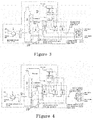
Fig. 1 illustrates an overall schematic diagram of a first gas-steam combined cycle centralized heat supply device of the present invention; -
Fig. 2 illustrates an overall schematic diagram of a second gas-steam combined cycle centralized heat supply device of the present invention; -
Fig. 3 illustrates an overall schematic diagram of a third gas-steam combined cycle centralized heat supply device of the present invention; -
Fig. 4 illustrates an overall schematic diagram of a fourth gas-steam combined cycle centralized heat supply device of the present invention; -
Fig. 5 illustrates an overall schematic diagram of a fifth gas-steam combined cycle centralized heat supply device of the present invention; -
Fig. 6 illustrates an overall schematic diagram of a sixth gas-steam combined cycle centralized heat supply device of the present invention; -
Fig. 7 illustrates an overall schematic diagram of a seventh gas-steam combined cycle centralized heat supply device of the present invention; -
Fig. 8 illustrates an overall schematic diagram of an eighth gas-steam combined cycle centralized heat supply device of the present invention. - The present invention will be described below in detail in combination with the drawings and the embodiments.
- As shown in
Fig. 1 , the present invention provides a gas-steam combined cycle centralized heat supply device, which comprises a gas-steam combined cycle system, a thermal station and a heating network return water heating system; and the gas-steam combined cycle system is connected with the thermal station through the heating network return water heating system. - The gas-steam combined cycle system comprises a
gas turbine 1, awaste heat boiler 2, a direct contact type flue gascondensation heat exchanger 3 and asteam turbine 4. An exhaust port of thegas turbine 1 is connected with a flue gas inlet of thewaste heat boiler 2. A flue gas outlet of thewaste heat boiler 2 is connected with a flue gas inlet of the direct contact type flue gascondensation heat exchanger 3, an steam outlet of thewaste heat boiler 2 is connected with an extraction steam inlet of thesteam turbine 4, and a drain water inlet of thewaste heat boiler 2 is connected with the heating network return water heating system. A first intermediate medium water inlet, a first intermediate medium water outlet, a second intermediate medium water inlet and a second intermediate medium water outlet of the direct contact type flue gascondensation heat exchanger 3 are connected to the heating network return water heating system; and an extraction steam outlet of thesteam turbine 4 is connected to the heating network return water heating system. - The thermal station comprises a hot water type
absorption heat pump 5 and a water-water heat exchanger 6. A heating network return water outlet and a heating network supply water inlet of the hot water typeabsorption heat pump 5 are connected to the heating network return water heating system, a heating network supply water outlet of the hot water typeabsorption heat pump 5 is connected with a heating network supply water inlet of the water-water heat exchanger 6, and a heating network return water inlet of the hot water typeabsorption heat pump 5 is connected with a heating network supply water outlet of the water-water heat exchanger 6. - As shown in
Fig. 1 , the heating network return water heating system of the present invention comprises a steam typeabsorption heat pump 7 for recovering flue gas waste heat and a steam-water heat exchanger 8. A heating network water inlet of the steam typeabsorption heat pump 7 for recovering flue gas waste heat is connected with the heating network return water outlet of the hot water typeabsorption heat pump 5, a heating network water outlet of the steam typeabsorption heat pump 7 for recovering flue gas waste heat is connected with a heating network water inlet of the steam-water heat exchanger 8, and a heating network water outlet of the steam-water heat exchanger 8 is connected with the heating network supply water inlet of the hot water typeabsorption heat pump 5. An intermediate medium water outlet and an intermediate medium water inlet of the steam typeabsorption heat pump 7 for recovering flue gas waste heat are respectively connected with the first intermediate medium water inlet and the first intermediate medium water outlet of the direct contact type flue gascondensation heat exchanger 3, a drain water outlet of the steam typeabsorption heat pump 7 for recovering flue gas waste heat and a drain water outlet of the steam-water heat exchanger 8 are connected with the drain water inlet of thewaste heat boiler 2, and an extraction steam inlet of the steam typeabsorption heat pump 7 for recovering flue gas waste heat and an extraction steam inlet of the steam-water heat exchanger 8 are connected to the extraction steam outlet of thesteam turbine 4. - In one preferred embodiment, as shown in
Fig. 2 , the heating network return water heating system comprises a steam typeabsorption heat pump 7 for recovering flue gas waste heat, a steam-water heat exchanger 8 and a power plant water-water heat exchanger 9. A heating network water inlet of the power plant water-water heat exchanger 9 is connected with the heating network return water outlet of the hot water typeabsorption heat pump 5, and a heating network water outlet of the power plant water-water heat exchanger 9 is connected with a heating network water inlet of the steam typeabsorption heat pump 7 for recovering flue gas waste heat. A heating network water outlet of the steam typeabsorption heat pump 7 for recovering flue gas waste heat is connected with a heating network water inlet of the steam-water heat exchanger 8, and a heating network water outlet of the steam-water heat exchanger 8 is connected with a heating network supply water inlet of the hot water typeabsorption heat pump 5. An intermediate medium water outlet and an intermediate medium water inlet of the steam typeabsorption heat pump 7 for recovering flue gas waste heat are respectively connected with the first intermediate medium water inlet and the first intermediate medium water outlet of the direct contact type flue gascondensation heat exchanger 3; an intermediate medium water outlet and an intermediate medium water inlet of the power plant water-water heat exchanger 9 are respectively connected with the second intermediate medium water inlet and the second intermediate medium water outlet of the direct contact type flue gascondensation heat exchanger 3; and a drain water outlet of the steam typeabsorption heat pump 7 for recovering flue gas waste heat and a drain water outlet of the steam-water heat exchanger 8 are connected to the drain water inlet of thewaste heat boiler 2, and an extraction steam inlet of the steam typeabsorption heat pump 7 for recovering flue gas waste heat and an extraction steam inlet of the steam-water heat exchanger 8 are connected to the extraction steam outlet of thesteam turbine 4. - In one preferred embodiment, as shown in
Fig. 3 , the heating network return water heating system comprises a steam typeabsorption heat pump 7 for recovering flue gas waste heat, a steam-water heat exchanger 8, a power plant water-water heat exchanger 9 and acondenser 10. A heating network water inlet of the power plant water-water heat exchanger 9 is connected with the heating network return water outlet of the hot water typeabsorption heat pump 5, and a heating network water outlet of the power plant water-water heat exchanger 9 is connected with a heating network water inlet of thecondenser 10. A heating network water outlet of thecondenser 10 is connected with a heating network water inlet of the steam typeabsorption heat pump 7 for recovering flue gas waste heat; a heating network water outlet of the steam typeabsorption heat pump 7 for recovering flue gas waste heat is connected with a heating network water inlet of the steam-water heat exchanger 8; and a heating network water outlet of the steam-water heat exchanger 8 is connected with the heating network supply water inlet of the hot water typeabsorption heat pump 5 in the thermal station. An intermediate medium water outlet and an intermediate medium water inlet of the steam typeabsorption heat pump 7 for recovering flue gas waste heat are respectively connected with the first intermediate medium water inlet and the first intermediate medium water outlet of the direct contact type flue gascondensation heat exchanger 3; an intermediate medium water outlet and an intermediate medium water inlet of the power plant water-water heat exchanger 9 are respectively connected with the second intermediate medium water inlet and the second intermediate medium water outlet of the direct contact type flue gascondensation heat exchanger 3; a drain water outlet of the steam typeabsorption heat pump 7 for recovering flue gas waste heat, a drain water outlet of the steam-water heat exchanger 8 and a drain water outlet of thecondenser 10 are connected to the drain water inlet of thewaste heat boiler 2; an extraction steam inlet of the steam typeabsorption heat pump 7 for recovering flue gas waste heat and an extraction steam inlet of the steam-water heat exchanger 8 are connected to the extraction steam outlet of thesteam turbine 4; and an exhaust steam inlet of thecondenser 10 is connected to an exhaust steam outlet of thesteam turbine 4. - In one preferred embodiment, as shown in
Fig. 4 , the heating network return water heating system comprises a steam typeabsorption heat pump 7 for recovering flue gas waste heat, a steam-water heat exchanger 8, a power plant water-water heat exchanger 9 and acondenser 10. A heating network water inlet of thecondenser 10 is connected with the heating network return water outlet of the hot water typeabsorption heat pump 5, a heating network water outlet of thecondenser 10 is connected with a heating network water inlet of the power plant water-water heat exchanger 9, and a heating network water outlet of the power plant water-water heat exchanger 9 is connected with a heating network water inlet of the steam typeabsorption heat pump 7 for recovering flue gas waste heat; and a heating network water outlet of the steam typeabsorption heat pump 7 for recovering flue gas waste heat is connected with a heating network water inlet of the steam-water heat exchanger 9, and a heating network water outlet of the steam-water heat exchanger 8 is connected with the heating network supply water inlet of the hot water typeabsorption heat pump 5. An intermediate medium water outlet and an intermediate medium water inlet of the steam typeabsorption heat pump 7 for recovering flue gas waste heat are respectively connected with the first intermediate medium water inlet and the first intermediate medium water outlet of the direct contact type flue gascondensation heat exchanger 3; an intermediate medium water outlet and an intermediate medium water inlet of the power plant water-water heat exchanger 9 are respectively connected with the second intermediate medium water inlet and the second intermediate medium water outlet of the direct contact type flue gascondensation heat exchanger 3; a drain water outlet of the steam typeabsorption heat pump 7 for recovering flue gas waste heat, a drain water outlet of the steam-water heat exchanger 8 and a drain water outlet of thecondenser 10 are connected to the drain water inlet of thewaste heat boiler 2, and an extraction steam inlet of the steam typeabsorption heat pump 7 for recovering flue gas waste heat and an extraction steam inlet of the steam-water heat exchanger 8 are connected to the extraction steam outlet of thesteam turbine 4; and an exhaust steam inlet of thecondenser 10 is connected to an exhaust steam outlet of thesteam turbine 4. - In one preferred embodiment, as shown in
Fig. 5 , the heating network return water heating system comprises a steam typeabsorption heat pump 7 for recovering flue gas waste heat, a steam-water heat exchanger 8, a power plant water-water heat exchanger 9 and acondenser 10. A heating network water inlet of the power plant water-water heat exchanger 9 and a heating network water inlet of thecondenser 10 are connected with the heating network return water outlet of the hot water typeabsorption heat pump 5; a heating network water outlet of the power plant water-water heat exchanger 9 and a heating network water outlet of thecondenser 10 are connected with a heating network water inlet of the steam typeabsorption heat pump 7 for recovering flue gas waste heat, and a heating network water outlet of the steam typeabsorption heat pump 7 for recovering flue gas waste heat is connected with a heating network water inlet of the steam-water heat exchanger 8; and a heating network water outlet of the steam-water heat exchanger 8 is connected with a heating network supply water inlet of the hot water typeabsorption heat pump 5. An intermediate medium water outlet and an intermediate medium water inlet of the steam typeabsorption heat pump 7 for recovering flue gas waste heat are respectively connected with the first intermediate medium water inlet and the first intermediate medium water outlet of the direct contact type flue gascondensation heat exchanger 3; an intermediate medium water outlet and an intermediate medium water inlet of the power plant water-water heat exchanger 9 are respectively connected with the second intermediate medium water inlet and the second intermediate medium water outlet of the direct contact type flue gascondensation heat exchanger 3; a drain water outlet of the steam typeabsorption heat pump 7 for recovering flue gas waste heat, a drain water outlet of the steam-water heat exchanger 8 and a drain water outlet of thecondenser 10 are connected to the drain water inlet of thewaste heat boiler 2; an extraction steam inlet of the steam typeabsorption heat pump 7 for recovering flue gas waste heat and an extraction steam inlet of the steam-water heat exchanger 8 are connected to the extraction steam outlet of thesteam turbine 4; and an exhaust steam inlet of thecondenser 10 is connected to an exhaust steam outlet of thesteam turbine 4. - In one preferred embodiment, as shown in
Fig. 6 , the heating network return water heating system comprises a steam typeabsorption heat pump 7 for recovering flue gas waste heat, a steam-water heat exchanger 8, acondenser 10 and a steam typeabsorption heat pump 11 for recovering exhaust steam waste heat. A heating network water inlet of the steam typeabsorption heat pump 11 for recovering exhaust steam waste heat is connected with the heating network return water outlet of the hot water typeabsorption heat pump 5, and a heating network water outlet of the steam typeabsorption heat pump 11 for recovering exhaust steam waste heat is connected with a heating network water inlet of the steam typeabsorption heat pump 7 for recovering flue gas waste heat; and an intermediate cooling circulating water outlet and an intermediate cooling circulating water inlet of the steam typeabsorption heat pump 11 for recovering exhaust steam waste heat are respectively connected with an intermediate cooling circulating water inlet and an intermediate cooling circulating water outlet of thecondenser 10. A heating network water outlet of the steam typeabsorption heat pump 7 for recovering flue gas waste heat is connected with a heating network water inlet of the steam-water heat exchanger 8; and a heating network water outlet of the steam-water heat exchanger 8 is connected with a heating network supply water inlet of the hot water typeabsorption heat pump 5. An intermediate medium water outlet and an intermediate medium water inlet of the steam typeabsorption heat pump 7 for recovering flue gas waste heat are respectively connected with the first intermediate medium water inlet and the first intermediate medium water outlet of the direct contact type flue gascondensation heat exchanger 3; a drain water outlet of the steam typeabsorption heat pump 7 for recovering flue gas waste heat, a drain water outlet of the steam-water heat exchanger 8, a drain water outlet of thecondenser 10 and a drain water outlet of the steam typeabsorption heat pump 11 for recovering exhaust steam waste heat are connected to the drain water inlet of thewaste heat boiler 2; an extraction steam inlet of the steam typeabsorption heat pump 7 for recovering flue gas waste heat, an extraction steam inlet of the steam-water heat exchanger 8 and an extraction steam inlet of the steam typeabsorption heat pump 11 for recovering exhaust steam waste heat are connected to the extraction steam outlet of thesteam turbine 4; and an exhaust steam inlet of thecondenser 10 is connected to an exhaust steam outlet of thesteam turbine 4. - In one preferred embodiment, as shown in
Fig. 7 , the heating network return water heating system comprises a steam typeabsorption heat pump 7 for recovering flue gas waste heat, a steam-water heat exchanger 8, a power plant water-water heat exchanger 9, acondenser 10 and a steam typeabsorption heat pump 11 for recovering exhaust steam waste heat. A heating network water inlet of the power plant water-water heat exchanger 9 is connected with the heating network return water outlet of the hot water typeabsorption heat pump 5, and a heating network water outlet of the power plant water-water heat exchanger 9 is connected with a heating network water inlet of the steam typeabsorption heat pump 11 for recovering exhaust steam waste heat; a heating network water outlet of the steam typeabsorption heat pump 11 for recovering exhaust steam waste heat is connected with a heating network water inlet of the steam typeabsorption heat pump 7 for recovering flue gas waste heat; and an intermediate cooling circulating water outlet and an intermediate cooling circulating water inlet of the steam typeabsorption heat pump 11 for recovering exhaust steam waste heat are respectively connected with an intermediate cooling circulating water inlet and an intermediate cooling circulating water outlet of thecondenser 10. A heating network water outlet of the steam typeabsorption heat pump 7 for recovering flue gas waste heat is connected with a heating network water inlet of the steam-water heat exchanger 8; and a heating network water outlet of the steam-water heat exchanger 8 is connected with the heating network supply water inlet of the hot water typeabsorption heat pump 5. An intermediate medium water outlet and an intermediate medium water inlet of the steam type absorption heat pump 7 for recovering flue gas waste heat are respectively connected with the first intermediate medium water inlet and the first intermediate medium water outlet of the direct contact type flue gas condensation heat exchanger 3; an intermediate medium water outlet and an intermediate medium water inlet of the power plant water-water heat exchanger 9 are respectively connected with the second intermediate medium water inlet and the second intermediate medium water outlet of the direct contact type flue gas condensation heat exchanger 3; a drain water outlet of the steam type absorption heat pump 7 for recovering flue gas waste heat, a drain water outlet of the steam-water heat exchanger 8, a drain water outlet of the condenser 10 and a drain water outlet of the steam type absorption heat pump 11 for recovering exhaust steam waste heat are connected to the drain water inlet of the waste heat boiler 2; an extraction steam inlet of the steam type absorption heat pump 7 for recovering flue gas waste heat, an extraction steam inlet of the steam-water heat exchanger 8 and an extraction steam inlet of the steam type absorption heat pump 11 for recovering exhaust steam waste heat are connected to the extraction steam outlet of the steam turbine 4; and an exhaust steam inlet of the condenser 10 is connected to an exhaust steam outlet of the steam turbine 4. - In one preferred embodiment, as shown in
Fig. 8 , the heating network return water heating system comprises a steam typeabsorption heat pump 7 for recovering flue gas waste heat, a steam-water heat exchanger 8, a power plant water-water heat exchanger 9, acondenser 10 and a steam typeabsorption heat pump 11 for recovering exhaust steam waste heat. A heating network water inlet of the condenser 10 is connected with the heating network return water outlet of the hot water type absorption heat pump 5; a heating network water outlet of the condenser 10 is connected with a heating network water inlet of the power plant water-water heat exchanger 9; a heating network water outlet of the power plant water-water heat exchanger 9 is connected with a heating network water inlet of the steam type absorption heat pump 7 for recovering flue gas waste heat; a heating network water outlet of the steam type absorption heat pump 7 for recovering flue gas waste heat is connected with a heating network water inlet of the steam type absorption heat pump 11 for recovering exhaust steam waste heat; a heating network water outlet of the steam type absorption heat pump 11 for recovering exhaust steam waste heat is connected with a heating network water inlet of the steam-water heat exchanger 8, an intermediate cooling circulating water outlet and an intermediate cooling circulating water inlet of the steam type absorption heat pump 11 for recovering exhaust steam waste heat are respectively connected with an intermediate cooling circulating water inlet and an intermediate cooling circulating water outlet of the condenser 10; and a heating network water outlet of the steam-water heat exchanger 8 is connected with a heating network supply water inlet of the hot water type absorption heat pump 5. A drain water outlet of the steam typeabsorption heat pump 7 for recovering flue gas waste heat, a drain water outlet of the steam-water heat exchanger 8, a drain water outlet of thecondenser 10 and a drain water outlet of the steam typeabsorption heat pump 11 for recovering exhaust steam waste heat are connected to the drain water inlet of thewaste heat boiler 2; an extraction steam inlet of the steam typeabsorption heat pump 7 for recovering flue gas waste heat, an extraction steam inlet of the steam-water heat exchanger 8 and an extraction steam inlet of the steam typeabsorption heat pump 11 for recovering exhaust steam waste heat are connected to the extraction steam outlet of thesteam turbine 4; and an exhaust steam inlet of thecondenser 10 is connected to an exhaust steam outlet of thesteam turbine 4. - In one preferred embodiment, a
water pump 12 is arranged between the thermal station and the heating network return water heating system and is used for delivering heating network low-temperature return water in the thermal station to the heating network return water heating system. - Based on the gas-steam combined cycle centralized heat supply device provided in the above-mentioned embodiments, the present invention further provides a gas-steam combined cycle centralized heat supply method, which comprises the following steps:
- 1) In a gas-steam combined cycle system, natural gas and air are mixed and combusted in a combustion chamber of a
gas turbine 1 to produce high-temperature flue gas, and the high-temperature flue gas flows into a combustion turbine of thegas turbine 1 to expand to do work and drive a power generator to generate power; after doing work, the flue gas enters awaste heat boiler 2 to heat boiler supply water in thewaste heat boiler 2 so as to produce high-temperature steam in thewaste heat boiler 2; the flue gas exhausted from thewaste heat boiler 2 enters a direct contact type flue gascondensation heat exchanger 3, is cooled and then is exhausted into the atmosphere, the high-temperature steam produced in thewaste heat boiler 2 enters asteam turbine 4 to do work to generate power, extraction steam is extracted from thesteam turbine 4 and the extracted extraction steam enters a heating network return water heating system. - 2) heating network low-temperature return water which is drained from the thermal station, enters the heating network return water heating system and is heated in the heating network return water heating system, and the heated heating network low-temperature return water is used as heating network high-temperature supply water which is returned to the thermal station, wherein intermediate medium water produced in the heating network return water heating system enters the direct contact type flue gas
condensation heat exchanger 3 and is heated by flue gas in the direct contact type flue gascondensation heat exchanger 3, and the heated intermediate medium water is returned to the heating network return water heating system; and extraction steam condensate produced in the heating network return water heating system is returned to thesteam boiler 2. - 3) The heating network high-temperature supply water returned to the thermal station is firstly used as a driving heat source, enters a hot water type
absorption heat pump 5, emits heat and is cooled in the hot water typeabsorption heat pump 5, then enters a water-water heat exchanger 6 in the thermal station to heat user supply water, is cooled in the water-water heat exchanger 6 in the thermal station, then again enters the hot water typeabsorption heat pump 5 as low-grade heat source, finally emits heat and is cooled to the designed temperature of heating network low-temperature return water and is used as the heating network low-temperature return water to enter the heating network return water heating system from the thermal station. - The above-mentioned embodiments are only used for describing the present invention. Structures, connecting manners, manufacturing processes and the like of components therein are variable. Equivalent transformations and improvements made on the basis of the technical solution of the present invention shall not be excluded from the protection range of the present invention.
Claims (10)
- A gas-steam combined cycle centralized heat supply device, characterized in that the gas-steam combined cycle centralized heat supply device comprises a gas-steam combined cycle system, a heating network return water heating system and a thermal station, and the gas-steam combined cycle system is connected with the thermal station through the heating network return water heating system;
the gas-steam combined cycle system comprises a gas turbine, a waste heat boiler, a direct contact type flue gas condensation heat exchanger and a steam turbine; an exhaust port of the gas turbine is connected with a flue gas inlet of the waste heat boiler; a flue gas outlet of the waste heat boiler is connected with a flue gas inlet of the direct contact type flue gas condensation heat exchanger, an steam outlet of the waste heat boiler is connected with an extraction steam inlet of the steam turbine, and a drain water inlet of the waste heat boiler is connected with the heating network return water heating system; a first intermediate medium water inlet, a first intermediate medium water outlet, a second intermediate medium water inlet and a second intermediate medium water outlet of the direct contact type flue gas condensation heat exchanger are connected to the heating network return water heating system; an extraction steam outlet of the steam turbine is connected to the heating network return water heating system;
the thermal station comprises a hot water type absorption heat pump and a water-water heat exchanger; and a heating network return water outlet and a heating network supply water inlet of the hot water type absorption heat pump are connected to the heating network return water heating system, a heating network supply water outlet of the hot water type absorption heat pump is connected with a heating network supply water inlet of the water-water heat exchanger, and a heating network return water inlet of the hot water type absorption heat pump is connected with a heating network supply water outlet of the water-water heat exchanger. - The gas-steam combined cycle centralized heat supply device according to claim 1, characterized in that the heating network return water heating system comprises a steam type absorption heat pump for recovering flue gas waste heat and a steam-water heat exchanger; a heating network water inlet of the steam type absorption heat pump for recovering flue gas waste heat is connected with the heating network return water outlet of the hot water type absorption heat pump, a heating network water outlet of the steam type absorption heat pump for recovering flue gas waste heat is connected with a heating network water inlet of the steam-water heat exchanger, and a heating network water outlet of the steam-water heat exchanger is connected with the heating network supply water inlet of the hot water type absorption heat pump; and an intermediate medium water outlet and an intermediate medium water inlet of the steam type absorption heat pump for recovering flue gas waste heat are respectively connected with the first intermediate medium water inlet and the first intermediate medium water outlet of the direct contact type flue gas condensation heat exchanger, a drain water outlet of the steam type absorption heat pump for recovering flue gas waste heat and a drain water outlet of the steam-water heat exchanger are connected with the drain water inlet of the waste heat boiler, and an extraction steam inlet of the steam type absorption heat pump for recovering flue gas waste heat and an extraction steam inlet of the steam-water heat exchanger are connected to the extraction steam outlet of the steam turbine.
- The gas-steam combined cycle centralized heat supply device according to claim 1, characterized in that the heating network return water heating system comprises a steam type absorption heat pump for recovering flue gas waste heat, a steam-water heat exchanger and a power plant water-water heat exchanger; a heating network water inlet of the power plant water-water heat exchanger is connected with the heating network return water outlet of the hot water type absorption heat pump, and a heating network water outlet of the power plant water-water heat exchanger is connected with a heating network water inlet of the steam type absorption heat pump for recovering flue gas waste heat; a heating network water outlet of the steam type absorption heat pump for recovering flue gas waste heat is connected with a heating network water inlet of the steam-water heat exchanger, and a heating network water outlet of the steam-water heat exchanger is connected with the heating network supply water inlet of the hot water type absorption heat pump; an intermediate medium water outlet and an intermediate medium water inlet of the steam type absorption heat pump for recovering flue gas waste heat are respectively connected with the first intermediate medium water inlet and the first intermediate medium water outlet of the direct contact type flue gas condensation heat exchanger; an intermediate medium water outlet and an intermediate medium water inlet of the power plant water-water heat exchanger are respectively connected with the second intermediate medium water inlet and the second intermediate medium water outlet of the direct contact type flue gas condensation heat exchanger; and a drain water outlet of the steam type absorption heat pump for recovering flue gas waste heat and a drain water outlet of the steam-water heat exchanger are connected to the drain water inlet of the waste heat boiler, and an extraction steam inlet of the steam type absorption heat pump for recovering flue gas waste heat and an extraction steam inlet of the steam-water heat exchanger are connected to the extraction steam outlet of the steam turbine.
- The gas-steam combined cycle centralized heat supply device according to claim 1, characterized in that the heating network return water heating system comprises a steam type absorption heat pump for recovering flue gas waste heat, a steam-water heat exchanger, a power plant water-water heat exchanger and a condenser; a heating network water inlet of the power plant water-water heat exchanger is connected with the heating network return water outlet of the hot water type absorption heat pump, and a heating network water outlet of the power plant water-water heat exchanger is connected with a heating network water inlet of the condenser; a heating network water outlet of the condenser is connected with a heating network water inlet of the steam type absorption heat pump for recovering flue gas waste heat; a heating network water outlet of the steam type absorption heat pump for recovering flue gas waste heat is connected with a heating network water inlet of the steam-water heat exchanger; a heating network water outlet of the steam-water heat exchanger is connected with the heating network supply water inlet of the hot water type absorption heat pump in the thermal station; an intermediate medium water outlet and an intermediate medium water inlet of the steam type absorption heat pump for recovering flue gas waste heat are respectively connected with the first intermediate medium water inlet and the first intermediate medium water outlet of the direct contact type flue gas condensation heat exchanger; an intermediate medium water outlet and an intermediate medium water inlet of the power plant water-water heat exchanger are respectively connected with the second intermediate medium water inlet and the second intermediate medium water outlet of the direct contact type flue gas condensation heat exchanger; a drain water outlet of the steam type absorption heat pump for recovering flue gas waste heat, a drain water outlet of the steam-water heat exchanger and a drain water outlet of the condenser are connected to the drain water inlet of the waste heat boiler; an extraction steam inlet of the steam type absorption heat pump for recovering flue gas waste heat and an extraction steam inlet of the steam-water heat exchanger are connected to the extraction steam outlet of the steam turbine; and an exhaust steam inlet of the condenser is connected to an exhaust steam outlet of the steam turbine.
- The gas-steam combined cycle centralized heat supply device according to claim 1, characterized in that the heating network return water heating system comprises a steam type absorption heat pump for recovering flue gas waste heat, a steam-water heat exchanger, a power plant water-water heat exchanger and a condenser; a heating network water inlet of the condenser is connected with the heating network return water outlet of the hot water type absorption heat pump, a heating network water outlet of the condenser is connected with a heating network water inlet of the power plant water-water heat exchanger, and a heating network water outlet of the power plant water-water heat exchanger is connected with a heating network water inlet of the steam type absorption heat pump for recovering flue gas waste heat; a heating network water outlet of the steam type absorption heat pump for recovering flue gas waste heat is connected with a heating network water inlet of the steam-water heat exchanger, and a heating network water outlet of the steam-water heat exchanger is connected with the heating network supply water inlet of the hot water type absorption heat pump; an intermediate medium water outlet and an intermediate medium water inlet of the steam type absorption heat pump for recovering flue gas waste heat are respectively connected with the first intermediate medium water inlet and the first intermediate medium water outlet of the direct contact type flue gas condensation heat exchanger; an intermediate medium water outlet and an intermediate medium water inlet of the power plant water-water heat exchanger are respectively connected with the second intermediate medium water inlet and the second intermediate medium water outlet of the direct contact type flue gas condensation heat exchanger; a drain water outlet of the steam type absorption heat pump for recovering flue gas waste heat, a drain water outlet of the steam-water heat exchanger and a drain water outlet of the condenser are connected to the drain water inlet of the waste heat boiler, and an extraction steam inlet of the steam type absorption heat pump for recovering flue gas waste heat and an extraction steam inlet of the steam-water heat exchanger are connected to the extraction steam outlet of the steam turbine; and an exhaust steam inlet of the condenser is connected to an exhaust steam outlet of the steam turbine.
- The gas-steam combined cycle centralized heat supply device according to claim 1, characterized in that the heating network return water heating system comprises a steam type absorption heat pump for recovering flue gas waste heat, a steam-water heat exchanger, a power plant water-water heat exchanger and a condenser; a heating network water inlet of the power plant water-water heat exchanger and a heating network water inlet of the condenser are connected with the heating network return water outlet of the hot water type absorption heat pump; a heating network water outlet of the power plant water-water heat exchanger and a heating network water outlet of the condenser are connected with a heating network water inlet of the steam type absorption heat pump for recovering flue gas waste heat, and a heating network water outlet of the steam type absorption heat pump for recovering flue gas waste heat is connected with a heating network water inlet of the steam-water heat exchanger; a heating network water outlet of the steam-water heat exchanger is connected with the heating network supply water inlet of the hot water type absorption heat pump; an intermediate medium water outlet and an intermediate medium water inlet of the steam type absorption heat pump for recovering flue gas waste heat are respectively connected with the first intermediate medium water inlet and the first intermediate medium water outlet of the direct contact type flue gas condensation heat exchanger; an intermediate medium water outlet and an intermediate medium water inlet of the power plant water-water heat exchanger are respectively connected with the second intermediate medium water inlet and the second intermediate medium water outlet of the direct contact type flue gas condensation heat exchanger; a drain water outlet of the steam type absorption heat pump for recovering flue gas waste heat, a drain water outlet of the steam-water heat exchanger and a drain water outlet of the condenser are connected to the drain water inlet of the waste heat boiler; an extraction steam inlet of the steam type absorption heat pump for recovering flue gas waste heat and an extraction steam inlet of the steam-water heat exchanger are connected to the extraction steam outlet of the steam turbine; and an exhaust steam inlet of the condenser is connected to an exhaust steam outlet of the steam turbine.
- The gas-steam combined cycle centralized heat supply device according to claim 1, characterized in that the heating network return water heating system comprises a steam type absorption heat pump for recovering flue gas waste heat, a steam-water heat exchanger, a condenser and a steam type absorption heat pump for recovering exhaust steam waste heat; a heating network water inlet of the steam type absorption heat pump for recovering exhaust steam waste heat is connected with the heating network return water outlet of the hot water type absorption heat pump, and a heating network water outlet of the steam type absorption heat pump for recovering exhaust steam waste heat is connected with a heating network water inlet of the steam type absorption heat pump for recovering flue gas waste heat; an intermediate cooling circulating water outlet and an intermediate cooling circulating water inlet of the steam type absorption heat pump for recovering exhaust steam waste heat are respectively connected with an intermediate cooling circulating water inlet and an intermediate cooling circulating water outlet of the condenser; a heating network water outlet of the steam type absorption heat pump for recovering flue gas waste heat is connected with a heating network water inlet of the steam-water heat exchanger; a heating network water outlet of the steam-water heat exchanger is connected with a heating network supply water inlet of the hot water type absorption heat pump; an intermediate medium water outlet and an intermediate medium water inlet of the steam type absorption heat pump for recovering flue gas waste heat are respectively connected with the first intermediate medium water inlet and the first intermediate medium water outlet of the direct contact type flue gas condensation heat exchanger; a drain water outlet of the steam type absorption heat pump for recovering flue gas waste heat, a drain water outlet of the steam-water heat exchanger, a drain water outlet of the condenser and a drain water outlet of the steam type absorption heat pump for recovering exhaust steam waste heat are connected to the drain water inlet of the waste heat boiler; an extraction steam inlet of the steam type absorption heat pump for recovering flue gas waste heat, an extraction steam inlet of the steam-water heat exchanger and an extraction steam inlet of the steam type absorption heat pump for recovering exhaust steam waste heat are connected to the extraction steam outlet of the steam turbine; and an exhaust steam inlet of the condenser is connected to an exhaust steam outlet of the steam turbine.
- The gas-steam combined cycle centralized heat supply device according to claim 1, characterized in that the heating network return water heating system comprises a steam type absorption heat pump for recovering flue gas waste heat, a steam-water heat exchanger, a power plant water-water heat exchanger, a condenser and a steam type absorption heat pump for recovering exhaust steam waste heat; a heating network water inlet of the power plant water-water heat exchanger is connected with the heating network return water outlet of the hot water type absorption heat pump, and a heating network water outlet of the power plant water-water heat exchanger is connected with a heating network water inlet of the steam type absorption heat pump for recovering exhaust steam waste heat; a heating network water outlet of the steam type absorption heat pump for recovering exhaust steam waste heat is connected with a heating network water inlet of the steam type absorption heat pump for recovering flue gas waste heat; an intermediate cooling circulating water outlet and an intermediate cooling circulating water inlet of the steam type absorption heat pump for recovering exhaust steam waste heat are respectively connected with an intermediate cooling circulating water inlet and an intermediate cooling circulating water outlet of the condenser; a heating network water outlet of the steam type absorption heat pump for recovering flue gas waste heat is connected with a heating network water inlet of the steam-water heat exchanger; a heating network water outlet of the steam-water heat exchanger is connected with the heating network supply water inlet of the hot water type absorption heat pump; an intermediate medium water outlet and an intermediate medium water inlet of the steam type absorption heat pump for recovering flue gas waste heat are respectively connected with the first intermediate medium water inlet and the first intermediate medium water outlet of the direct contact type flue gas condensation heat exchanger; an intermediate medium water outlet and an intermediate medium water inlet of the power plant water-water heat exchanger are respectively connected with the second intermediate medium water inlet and the second intermediate medium water outlet of the direct contact type flue gas condensation heat exchanger; a drain water outlet of the steam type absorption heat pump for recovering flue gas waste heat, a drain water outlet of the steam-water heat exchanger, a drain water outlet of the condenser and a drain water outlet of the steam type absorption heat pump for recovering exhaust steam waste heat are connected to the drain water inlet of the waste heat boiler; an extraction steam inlet of the steam type absorption heat pump for recovering flue gas waste heat, an extraction steam inlet of the steam-water heat exchanger and an extraction steam inlet of the steam type absorption heat pump for recovering exhaust steam waste heat are connected to the extraction steam outlet of the steam turbine; and an exhaust steam inlet of the condenser is connected to an exhaust steam outlet of the steam turbine.
- The gas-steam combined cycle centralized heat supply device according to claim 1, characterized in that the heating network return water heating system comprises a steam type absorption heat pump for recovering flue gas waste heat, a steam-water heat exchanger, a power plant water-water heat exchanger, a condenser and a steam type absorption heat pump for recovering exhaust steam waste heat; a heating network water inlet of the condenser is connected with the heating network return water outlet of the hot water type absorption heat pump; a heating network water outlet of the condenser is connected with a heating network water inlet of the power plant water-water heat exchanger; a heating network water outlet of the power plant water-water heat exchanger is connected with a heating network water inlet of the steam type absorption heat pump for recovering flue gas waste heat; a heating network water outlet of the steam type absorption heat pump for recovering flue gas waste heat is connected with a heating network water inlet of the steam type absorption heat pump for recovering exhaust steam waste heat; a heating network water outlet of the steam type absorption heat pump for recovering exhaust steam waste heat is connected with a heating network water inlet of the steam-water heat exchanger, an intermediate cooling circulating water outlet and an intermediate cooling circulating water inlet of the steam type absorption heat pump for recovering exhaust steam waste heat are respectively connected with an intermediate cooling circulating water inlet and an intermediate cooling circulating water outlet of the condenser; a heating network water outlet of the steam-water heat exchanger is connected with the heating network supply water inlet of the hot water type absorption heat pump; a drain water outlet of the steam type absorption heat pump for recovering flue gas waste heat, a drain water outlet of the steam-water heat exchanger, a drain water outlet of the condenser and a drain water outlet of the steam type absorption heat pump for recovering exhaust steam waste heat are connected to the drain water inlet of the waste heat boiler; an extraction steam inlet of the steam type absorption heat pump for recovering flue gas waste heat, an extraction steam inlet of the steam-water heat exchanger and an extraction steam inlet of the steam type absorption heat pump for recovering exhaust steam waste heat are connected to the extraction steam outlet of the steam turbine; and an exhaust steam inlet of the condenser is connected to an exhaust steam outlet of the steam turbine.
- A heat supply method of the gas-steam combined cycle centralized heat supply device according to any one of claims 1-9, comprising the following steps:1) in the gas-steam combined cycle system, natural gas and air are mixed and combusted in a combustion chamber of the gas turbine to produce high-temperature flue gas, and the high-temperature flue gas flows into a combustion turbine of the gas turbine to expand to do work and drive a power generator to generate power; after doing work, the flue gas enters the waste heat boiler to heat boiler supply water in the waste heat boiler so as to produce high-temperature steam in the waste heat boiler; the flue gas exhausted from the waste heat boiler enters the direct contact type flue gas condensation heat exchanger, is cooled and then is exhausted into the atmosphere, the high-temperature steam produced in the waste heat boiler enters a steam turbine to do work to generate power, extraction steam is extracted from the steam turbine and the extracted extraction steam enters the heating network return water heating system;2) heating network low-temperature return water which is drained from the thermal station, enters the heating network return water heating system and is heated in the heating network return water heating system, and the heated heating network low-temperature return water is used as heating network high-temperature supply water which is returned to the thermal station, wherein intermediate medium water produced in the heating network return water heating system enters the direct contact type flue gas condensation heat exchanger and is heated by flue gas in the direct contact type flue gas condensation heat exchanger, and the heated intermediate medium water is returned to the heating network return water heating system; and extraction steam condensate produced in the heating network return water heating system is returned to the steam boiler;3) the heating network high-temperature supply water returned to the thermal station is firstly used as a driving heat source, enters the hot water type absorption heat pump, emits heat and is cooled in the hot water type absorption heat pump, then enters the water-water heat exchanger in the thermal station to heat user supply water, is cooled in the water-water heat exchanger in the thermal station, then again enters the hot water type absorption heat pump as low-grade heat source, finally emits heat and is cooled to the designed temperature of heating network low-temperature return water and is used as the heating network low-temperature return water to enter the heating network return water heating system from the thermal station.
Applications Claiming Priority (2)
| Application Number | Priority Date | Filing Date | Title |
|---|---|---|---|
| CN201510009398.XA CN104534539A (en) | 2015-01-08 | 2015-01-08 | Gas steam combined cycle central heating device and heating method |
| PCT/CN2015/089348 WO2016110124A1 (en) | 2015-01-08 | 2015-09-10 | Gas steam combined cycle central heating device and heating method |
Publications (3)
| Publication Number | Publication Date |
|---|---|
| EP3064841A1 true EP3064841A1 (en) | 2016-09-07 |
| EP3064841A4 EP3064841A4 (en) | 2017-10-11 |
| EP3064841B1 EP3064841B1 (en) | 2019-01-02 |
Family
ID=52850118
Family Applications (1)
| Application Number | Title | Priority Date | Filing Date |
|---|---|---|---|
| EP15826126.3A Not-in-force EP3064841B1 (en) | 2015-01-08 | 2015-09-10 | Gas steam combined cycle central heating device |
Country Status (7)
| Country | Link |
|---|---|
| US (1) | US10823015B2 (en) |
| EP (1) | EP3064841B1 (en) |
| JP (1) | JP6117444B2 (en) |
| KR (1) | KR102071105B1 (en) |
| CN (1) | CN104534539A (en) |
| DK (1) | DK3064841T3 (en) |
| WO (1) | WO2016110124A1 (en) |
Cited By (3)
| Publication number | Priority date | Publication date | Assignee | Title |
|---|---|---|---|---|
| CN109539293A (en) * | 2018-11-06 | 2019-03-29 | 清华大学 | A kind of system and its operation method of coal-fired flue-gas minimum discharge collaboration UTILIZATION OF VESIDUAL HEAT IN |
| CN113998751A (en) * | 2021-11-30 | 2022-02-01 | 华能营口热电有限责任公司 | System for desulfurization slurry flash distillation is carried hot water intaking |
| WO2026082941A1 (en) | 2024-10-18 | 2026-04-23 | Dall Energy Aps | Method and system for flexible heating plant by integration of biomass heating system and electrical heat pump system |
Families Citing this family (63)
| Publication number | Priority date | Publication date | Assignee | Title |
|---|---|---|---|---|
| CN104534539A (en) | 2015-01-08 | 2015-04-22 | 清华大学 | Gas steam combined cycle central heating device and heating method |
| CN104964479A (en) * | 2015-07-07 | 2015-10-07 | 中能世华(北京)节能科技有限公司 | Fuel gas combined heat and power generation heating supply system based on absorption-type heat exchange |
| CN105114936A (en) * | 2015-09-06 | 2015-12-02 | 中国华能集团清洁能源技术研究院有限公司 | System and method for maximum utilization of combined cycle low-temperature flue gas residual heat |
| CN105222203A (en) * | 2015-11-04 | 2016-01-06 | 清华大学 | A kind of novel gas cogeneration of heat and power central heating device |
| CN105484816B (en) * | 2015-12-31 | 2017-08-04 | 中国能源建设集团广东省电力设计研究院有限公司 | Combustion and steam association system and its progress control method |
| CN105605647A (en) * | 2016-02-03 | 2016-05-25 | 清华大学 | Synergic-purification all-heat-recovery combined heat and power generation system |
| CN106369804B (en) * | 2016-08-31 | 2019-05-24 | 中节能科技投资有限公司 | High-effect heat regenerative system |
| CN207394945U (en) * | 2016-10-09 | 2018-05-22 | 燕山大学 | A kind of step heating system using combined heat pump recycling exhaust steam of electric power plant waste heat |
| CN106594842B (en) * | 2016-12-30 | 2022-05-13 | 何宗衡 | Gas-electric hybrid heating unit |
| KR101842713B1 (en) * | 2017-11-16 | 2018-03-28 | 주식회사 동광보일러 | Waste heat recovery apparatus of steam boiler |
| CN107764122B (en) * | 2017-11-20 | 2023-09-22 | 济南热力集团有限公司 | A composite cascade utilization system for large temperature difference cold water based on waste heat utilization |
| CN108005741B (en) * | 2017-12-14 | 2023-07-04 | 华电电力科学研究院有限公司 | Cogeneration system for improving heat supply safety of back condensation and back extraction and adjustment method |
| CN108798898B (en) * | 2018-04-20 | 2023-11-28 | 华电电力科学研究院有限公司 | System and method for supplying steam and hot water by combining proton exchange membrane fuel cell and gas turbine |
| CN108825364B (en) * | 2018-06-22 | 2021-05-04 | 中船动力有限公司 | Natural gas generating set waste heat and carbon dioxide utilization device |
| CN109237509A (en) * | 2018-08-30 | 2019-01-18 | 华电电力科学研究院有限公司 | A kind of method and device that indirect air cooling unit circulating water afterheat is recycled to boiler supply air system |
| CN109237587B (en) * | 2018-09-13 | 2023-04-28 | 华电电力科学研究院有限公司 | Low-vacuum heat supply system coupled with large-temperature-difference heat pump and operation method |
| CN109099745B (en) * | 2018-10-08 | 2024-03-01 | 公安县人民医院 | Hot water supply system for recycling and heating by utilizing hospital steam |
| CN109322716B (en) * | 2018-10-16 | 2021-06-11 | 山东华电节能技术有限公司 | Gas-steam combined cycle high back pressure heat supply unit and rotor-changing non-stop combustion machine method |
| CN109595046B (en) * | 2018-11-23 | 2024-03-19 | 中国大唐集团科学技术研究院有限公司火力发电技术研究院 | Large-scale coal-fired unit boiler waste heat and steam turbine waste heat coupling full recovery power generation system |
| CN109855147B (en) * | 2019-02-02 | 2023-04-28 | 华电电力科学研究院有限公司 | Combined cycle device based on heat supply and power peak regulation coupling and operation method thereof |
| CN111578301B (en) * | 2019-02-19 | 2022-08-09 | 北京热科能源技术研究有限公司 | Flue gas waste heat recovery system |
| CN110230521B (en) * | 2019-03-12 | 2023-09-19 | 华电电力科学研究院有限公司 | Cascade heating system for heat pump by cutting off steam inlet coupling of low-pressure cylinder of thermoelectric unit and adjusting method |
| CN109751652B (en) * | 2019-03-19 | 2024-02-23 | 中国建筑标准设计研究院有限公司 | High back pressure and heat pump combined heat supply system of 300MW and above grade wet cooling unit |
| KR102387283B1 (en) * | 2019-12-05 | 2022-04-18 | 주식회사 부-스타 | Gas boiler system and mixer |
| CN110849022A (en) * | 2019-12-06 | 2020-02-28 | 华北电力科学研究院有限责任公司 | Heat gradient utilization system for indirect air cooling system |
| CN110873354A (en) * | 2019-12-23 | 2020-03-10 | 北京市热力集团有限责任公司 | One-machine multi-effect heat pump system for peak regulation heat supply plant and heat pump control method |
| CN111442292A (en) * | 2020-05-26 | 2020-07-24 | 大唐环境产业集团股份有限公司 | A waste heat and water recovery system for a coal-fired power station |
| CN111594288B (en) * | 2020-06-08 | 2024-07-26 | 威立雅(哈尔滨)热电有限公司 | Heat energy recovery device of steam turbine shaft seal heater |
| CN112096470B (en) * | 2020-09-29 | 2022-08-02 | 西安热工研究院有限公司 | Liquid compressed air energy storage peak regulation system and method coupled with heating system |
| CN112129005A (en) * | 2020-10-19 | 2020-12-25 | 华能国际电力股份有限公司 | A multi-energy complementary energy station for a combined cycle power plant |
| FI129538B (en) * | 2020-11-16 | 2022-04-14 | Valmet Technologies Oy | Method and arrangement |
| CN112413712A (en) * | 2020-11-25 | 2021-02-26 | 双良节能系统股份有限公司 | Low-low temperature flue gas waste heat recovery heating system of coal-fired boiler |
| CN114576693B (en) * | 2020-11-30 | 2024-02-27 | 上海本家空调系统有限公司 | Gas heat pump heating system |
| CN112460838B (en) * | 2020-12-07 | 2026-04-24 | 贵州中建建筑科研设计院有限公司 | A natural gas distributed energy - ground source heat pump power supply system |
| CN112664918B (en) * | 2020-12-26 | 2021-09-21 | 龙游县金怡热电有限公司 | Gas and steam combined cycle central heating device and heating method |
| CN112944426B (en) * | 2021-03-17 | 2025-06-06 | 联美智慧能源科技(沈阳)有限公司 | A multi-source complementary heating system and method for cascaded energy utilization |
| CN113028645A (en) * | 2021-03-30 | 2021-06-25 | 青岛新奥能源有限公司 | Flue gas waste heat and condensation recovery system of gas-fired hot water boiler |
| CN112944451B (en) * | 2021-04-15 | 2022-05-27 | 晟源高科(北京)科技有限公司 | Natural gas energy supplementing graded utilization system based on pressure isolation station and adjusting method |
| CN113446582A (en) * | 2021-06-22 | 2021-09-28 | 浙江菲达环保科技股份有限公司 | Energy-saving, water-saving and white-removing treatment system and method suitable for gas power plant |
| CN113375211B (en) * | 2021-06-28 | 2022-10-11 | 大唐环境产业集团股份有限公司 | Coal-fired unit heat supply system and operation method |
| CN113375210B (en) * | 2021-06-28 | 2022-03-01 | 大唐环境产业集团股份有限公司 | Cold end waste heat supply method and system of coupling absorption heat pump |
| CN113532134B (en) * | 2021-07-28 | 2023-02-03 | 首钢京唐钢铁联合有限责任公司 | Sintering waste heat recycling device and method |
| CN113513385A (en) * | 2021-07-30 | 2021-10-19 | 中国华能集团清洁能源技术研究院有限公司 | A high thermoelectric ratio IGCC cogeneration system and method |
| CN113566260B (en) * | 2021-08-17 | 2024-05-07 | 清华大学 | A composite heat pump heating system and method |
| CN113686190B (en) * | 2021-08-31 | 2024-02-02 | 济南美联同创能源科技有限公司 | System and method for comprehensively recycling and utilizing low-temperature waste heat |
| CN215637465U (en) * | 2021-09-10 | 2022-01-25 | 青岛新奥能源有限公司 | Multi-heat-source complementary combined heating system |
| CN113623711B (en) * | 2021-09-15 | 2023-05-02 | 西安热工研究院有限公司 | Heat accumulation and heat supply system with wide-range electric output adjustment of gas-steam combined unit |
| CN115823774A (en) * | 2021-09-17 | 2023-03-21 | 大连经济技术开发区供热有限公司 | An absorption heat pump and boiler gas turbine unit |
| CN113899006B (en) * | 2021-11-09 | 2023-03-21 | 东北电力大学 | A heat supply system that utilizes low-pressure heating and drainage to drive heat pumps to recover waste heat from circulating water |
| CN114811630A (en) * | 2021-11-26 | 2022-07-29 | 清华大学 | Flue gas waste heat recovery system with heat pump coupled with gas-water surface type heat exchanger |
| CN114111094B (en) * | 2021-11-30 | 2023-02-28 | 中国华能集团清洁能源技术研究院有限公司 | A desulfurization slurry waste heat recovery device using unit extraction and absorption heat pump |
| CN114046556B (en) * | 2021-12-09 | 2025-01-28 | 中国华能集团清洁能源技术研究院有限公司 | A power generation and heating device and method for cascade utilization of high temperature gas-cooled reactors |
| CN114776405B (en) * | 2022-04-11 | 2024-01-26 | 华北电力科学研究院有限责任公司 | A heating protection control method and device for a combined heat and power unit |
| US12455098B2 (en) | 2022-04-12 | 2025-10-28 | The Cleaver-Brooks Company, Inc. | Thermal efficiency system and method for boiler plant |
| CN115013852A (en) * | 2022-05-31 | 2022-09-06 | 华能伊敏煤电有限责任公司 | Multi-unit heat supply drainage waste heat deep recycling device and method |
| CN115164262B (en) * | 2022-07-13 | 2024-01-23 | 西安热工研究院有限公司 | A waste heat and water recovery system and operation method of a cogeneration unit |
| CN115307172B (en) * | 2022-08-17 | 2023-05-26 | 饶阳县胜岳锅炉制造有限公司 | Environment-friendly boiler flue gas waste heat recovery device |
| CN115823638B (en) * | 2022-09-30 | 2025-08-19 | 西安法凯涞玛能源科技有限公司 | Cogeneration waste heat utilization system |
| CN116221804A (en) * | 2022-12-30 | 2023-06-06 | 江苏港嘉节能科技有限公司 | Method and system for recycling waste heat of circulating water of thermal power plant |
| CN116928723A (en) * | 2023-07-21 | 2023-10-24 | 福建龙净环保股份有限公司 | Waste heat recovery system and waste heat recovery method of coal-fired unit |
| CN116951517A (en) * | 2023-07-26 | 2023-10-27 | 西安热工研究院有限公司 | Combined heating system utilizing waste heat of gas turbine |
| CN119436904B (en) * | 2024-11-04 | 2025-11-25 | 重庆电子科技职业大学 | A waste heat recovery application system and control method suitable for steam exhaust. |
| CN119088125B (en) * | 2024-11-05 | 2025-01-28 | 北京新兴合众科技有限公司 | Steam boiler flue gas waste heat recovery system, control method, device and medium thereof |
Family Cites Families (23)
| Publication number | Priority date | Publication date | Assignee | Title |
|---|---|---|---|---|
| JPS58107803A (en) * | 1981-12-21 | 1983-06-27 | Toshiba Corp | Power generation plant |
| FR2572169B1 (en) * | 1984-10-18 | 1987-01-02 | Armines | THERMOELECTRIC MICROCENTRAL |
| JPH04292757A (en) * | 1991-03-18 | 1992-10-16 | Mitsubishi Heavy Ind Ltd | Cogeneration plant system |
| JPH06129211A (en) * | 1992-10-21 | 1994-05-10 | Shimizu Corp | Thermoelectric supply system |
| JPH06201218A (en) * | 1992-12-28 | 1994-07-19 | Mitsui Eng & Shipbuild Co Ltd | High temperature output-type large pressure rise width hybrid heat pump |
| JPH094807A (en) * | 1995-06-15 | 1997-01-10 | Pado:Kk | Steam turbine power generating device, heating feed water by waste heat |
| DE19545668A1 (en) * | 1995-12-07 | 1997-06-12 | Asea Brown Boveri | Method for operating a gas turbine group combined with a waste heat steam generator and a steam consumer |
| JP2002266656A (en) | 2001-03-07 | 2002-09-18 | Ishikawajima Harima Heavy Ind Co Ltd | Gas turbine cogeneration system |
| JP2007205187A (en) * | 2006-01-31 | 2007-08-16 | Hitachi Engineering & Services Co Ltd | Heat recovery system attached to boiler-steam turbine system |
| CN101761393A (en) * | 2010-02-11 | 2010-06-30 | 华北电力大学 | Fuel gas and steam combined circulating system with gas compressor being driven by steam turbine |
| CN101858231B (en) * | 2010-04-07 | 2013-05-22 | 清华大学 | Energy supply system mainly through gas and steam combined cycle cogeneration |
| CN102393004A (en) * | 2010-09-30 | 2012-03-28 | 上海锅炉厂有限公司 | Fuel gas-steam combined cycle heat power plant |
| DK2630342T3 (en) * | 2010-10-19 | 2014-12-15 | Alstom Technology Ltd | Method for operation of a gas / steam-combi power plant with cogeneration and a gas / steam-combi power plant for carrying out the process |
| RU2623568C2 (en) * | 2011-03-01 | 2017-06-27 | Дженерал Электрик Текнолоджи Гмбх | Combined cycle power plant |
| CN102242946B (en) * | 2011-04-29 | 2013-10-16 | 清华大学 | Concentrated heat supply system for reclaiming smoke afterheat by absorption heat pump |
| CN102359739B (en) | 2011-09-14 | 2013-06-12 | 北京中科华誉能源技术发展有限责任公司 | Gas-steam circulation heating-electricity-cooling combined supply system and method for thermal power plant with zero energy loss rate |
| CN102407070B (en) * | 2011-11-21 | 2013-12-11 | 北京建筑工程学院 | Composite equipment for flue gas waste heat recovery and dust cleaning |
| KR101320593B1 (en) * | 2012-02-08 | 2013-10-23 | 지에스파워주식회사 | Cogeneration system using heat pump |
| CN102878603B (en) | 2012-10-30 | 2014-10-15 | 哈尔滨工业大学 | Gas-steam circulation combined double-stage coupling heat pump heat supply device |
| CN103759283B (en) * | 2014-01-10 | 2016-02-10 | 清华大学 | A kind of spray-absorption formula combustion gas flue gas total heat recovery and desulfurization denitration method and device |
| CN204082237U (en) * | 2014-08-29 | 2015-01-07 | 中国华能集团清洁能源技术研究院有限公司 | The IGCC thermal power cogeneration central heating system of recovery waste heat |
| CN104197397A (en) * | 2014-09-23 | 2014-12-10 | 大连葆光节能空调设备厂 | Energy-saving heat supply system for decreasing temperature of heating return water and recovering waste heat of thermal power plant |
| CN104534539A (en) | 2015-01-08 | 2015-04-22 | 清华大学 | Gas steam combined cycle central heating device and heating method |
-
2015
- 2015-01-08 CN CN201510009398.XA patent/CN104534539A/en active Pending
- 2015-09-10 KR KR1020167003301A patent/KR102071105B1/en not_active Expired - Fee Related
- 2015-09-10 US US14/910,228 patent/US10823015B2/en not_active Expired - Fee Related
- 2015-09-10 DK DK15826126.3T patent/DK3064841T3/en active
- 2015-09-10 JP JP2016535633A patent/JP6117444B2/en not_active Expired - Fee Related
- 2015-09-10 WO PCT/CN2015/089348 patent/WO2016110124A1/en not_active Ceased
- 2015-09-10 EP EP15826126.3A patent/EP3064841B1/en not_active Not-in-force
Cited By (4)
| Publication number | Priority date | Publication date | Assignee | Title |
|---|---|---|---|---|
| CN109539293A (en) * | 2018-11-06 | 2019-03-29 | 清华大学 | A kind of system and its operation method of coal-fired flue-gas minimum discharge collaboration UTILIZATION OF VESIDUAL HEAT IN |
| CN109539293B (en) * | 2018-11-06 | 2024-01-26 | 清华大学 | A system and operation method for ultra-low emission and coordinated waste heat utilization of coal-fired flue gas |
| CN113998751A (en) * | 2021-11-30 | 2022-02-01 | 华能营口热电有限责任公司 | System for desulfurization slurry flash distillation is carried hot water intaking |
| WO2026082941A1 (en) | 2024-10-18 | 2026-04-23 | Dall Energy Aps | Method and system for flexible heating plant by integration of biomass heating system and electrical heat pump system |
Also Published As
| Publication number | Publication date |
|---|---|
| CN104534539A (en) | 2015-04-22 |
| EP3064841B1 (en) | 2019-01-02 |
| DK3064841T3 (en) | 2019-04-15 |
| EP3064841A4 (en) | 2017-10-11 |
| KR102071105B1 (en) | 2020-03-02 |
| US10823015B2 (en) | 2020-11-03 |
| KR20170102793A (en) | 2017-09-12 |
| US20180223699A1 (en) | 2018-08-09 |
| WO2016110124A1 (en) | 2016-07-14 |
| JP6117444B2 (en) | 2017-04-19 |
| JP2017510742A (en) | 2017-04-13 |
Similar Documents
| Publication | Publication Date | Title |
|---|---|---|
| US10823015B2 (en) | Gas-steam combined cycle centralized heat supply device and heat supply method | |
| CN109681281B (en) | A biomass cogeneration system that can simultaneously recover spent steam and flue gas waste heat | |
| KR100975276B1 (en) | Local heating water feeding system using absorbing type heat pump | |
| CN103244214B (en) | Smoke condensation heat recovery combined heat and power supply system based on organic Rankine cycle | |
| CN101858231B (en) | Energy supply system mainly through gas and steam combined cycle cogeneration | |
| CN201443978U (en) | Carbon calciner waste heat power generation system | |
| CN103629857A (en) | Heat and power cogeneration centralized heat supply system based on heat pump | |
| Eze et al. | Advancements in energy efficiency technologies for thermal systems: A comprehensive review | |
| KR20130086397A (en) | The power efficiency improvement by using absorption heat pump in power plant system | |
| CN103967544A (en) | Waste heat utilization system of gas-steam combined cycle generator set | |
| CN103398385B (en) | The residual neat recovering system of a kind of boats and ships incinerator and power set and recovery method | |
| Jaber et al. | Domestic thermoelectric cogeneration drying system: Thermal modeling and case study | |
| CN205779061U (en) | Coal mine gas gradient thermoelectric cold supply system | |
| CN203717051U (en) | Combined cycling low-temperature exhaust heat recycling device | |
| CN203035350U (en) | Britten-hybrid combined steam rankine cycle power generation device | |
| Özbek et al. | District heating and power generation based flue gas waste heat recovery | |
| RU2611138C1 (en) | Method of operating combined-cycle power plant | |
| RU2693567C1 (en) | Method of operation of steam-gas plant of power plant | |
| CN203547925U (en) | Gas-steam combined cycle power plant | |
| RU121863U1 (en) | STEAM GAS INSTALLATION | |
| RU2740670C1 (en) | Method of operation of steam-gas plant of power plant | |
| CN207934946U (en) | A kind of system improving natural gas region cogeneration utilization efficiency of heat energy | |
| CN203783646U (en) | Medium temperature medium pressure steam and low pressure saturated steam power generating device in metallurgy industry | |
| RU118360U1 (en) | INSTALLATION OF ELECTRIC-HEAT-WATER SUPPLY OF ENTERPRISES OF MINING, TRANSPORT AND PROCESSING OF HYDROCARBON RAW MATERIALS | |
| CN105114267A (en) | Solar-energy low-temperature steam power generation system |
Legal Events
| Date | Code | Title | Description |
|---|---|---|---|
| PUAI | Public reference made under article 153(3) epc to a published international application that has entered the european phase |
Free format text: ORIGINAL CODE: 0009012 |
|
| 17P | Request for examination filed |
Effective date: 20160204 |
|
| AK | Designated contracting states |
Kind code of ref document: A1 Designated state(s): AL AT BE BG CH CY CZ DE DK EE ES FI FR GB GR HR HU IE IS IT LI LT LU LV MC MK MT NL NO PL PT RO RS SE SI SK SM TR |
|
| AX | Request for extension of the european patent |
Extension state: BA ME |
|
| A4 | Supplementary search report drawn up and despatched |
Effective date: 20170913 |
|
| RIC1 | Information provided on ipc code assigned before grant |
Ipc: F24D 3/18 20060101AFI20170907BHEP Ipc: F01K 17/02 20060101ALI20170907BHEP Ipc: F01K 23/10 20060101ALI20170907BHEP |
|
| DAV | Request for validation of the european patent (deleted) | ||
| DAX | Request for extension of the european patent (deleted) | ||
| GRAP | Despatch of communication of intention to grant a patent |
Free format text: ORIGINAL CODE: EPIDOSNIGR1 |
|
| STAA | Information on the status of an ep patent application or granted ep patent |
Free format text: STATUS: GRANT OF PATENT IS INTENDED |
|
| INTG | Intention to grant announced |
Effective date: 20180727 |
|
| GRAS | Grant fee paid |
Free format text: ORIGINAL CODE: EPIDOSNIGR3 |
|
| GRAA | (expected) grant |
Free format text: ORIGINAL CODE: 0009210 |
|
| STAA | Information on the status of an ep patent application or granted ep patent |
Free format text: STATUS: THE PATENT HAS BEEN GRANTED |
|
| AK | Designated contracting states |
Kind code of ref document: B1 Designated state(s): AL AT BE BG CH CY CZ DE DK EE ES FI FR GB GR HR HU IE IS IT LI LT LU LV MC MK MT NL NO PL PT RO RS SE SI SK SM TR |
|
| REG | Reference to a national code |
Ref country code: GB Ref legal event code: FG4D |
|
| REG | Reference to a national code |
Ref country code: CH Ref legal event code: EP Ref country code: AT Ref legal event code: REF Ref document number: 1084878 Country of ref document: AT Kind code of ref document: T Effective date: 20190115 |
|
| REG | Reference to a national code |
Ref country code: DE Ref legal event code: R096 Ref document number: 602015022988 Country of ref document: DE |
|
| REG | Reference to a national code |
Ref country code: IE Ref legal event code: FG4D |
|
| REG | Reference to a national code |
Ref country code: DK Ref legal event code: T3 Effective date: 20190408 |
|
| REG | Reference to a national code |
Ref country code: SE Ref legal event code: TRGR |
|
| REG | Reference to a national code |
Ref country code: NL Ref legal event code: MP Effective date: 20190102 |
|
| REG | Reference to a national code |
Ref country code: LT Ref legal event code: MG4D |
|
| REG | Reference to a national code |
Ref country code: AT Ref legal event code: MK05 Ref document number: 1084878 Country of ref document: AT Kind code of ref document: T Effective date: 20190102 |
|
| PG25 | Lapsed in a contracting state [announced via postgrant information from national office to epo] |
Ref country code: NL Free format text: LAPSE BECAUSE OF FAILURE TO SUBMIT A TRANSLATION OF THE DESCRIPTION OR TO PAY THE FEE WITHIN THE PRESCRIBED TIME-LIMIT Effective date: 20190102 |
|
| PG25 | Lapsed in a contracting state [announced via postgrant information from national office to epo] |
Ref country code: LT Free format text: LAPSE BECAUSE OF FAILURE TO SUBMIT A TRANSLATION OF THE DESCRIPTION OR TO PAY THE FEE WITHIN THE PRESCRIBED TIME-LIMIT Effective date: 20190102 Ref country code: PL Free format text: LAPSE BECAUSE OF FAILURE TO SUBMIT A TRANSLATION OF THE DESCRIPTION OR TO PAY THE FEE WITHIN THE PRESCRIBED TIME-LIMIT Effective date: 20190102 Ref country code: ES Free format text: LAPSE BECAUSE OF FAILURE TO SUBMIT A TRANSLATION OF THE DESCRIPTION OR TO PAY THE FEE WITHIN THE PRESCRIBED TIME-LIMIT Effective date: 20190102 Ref country code: PT Free format text: LAPSE BECAUSE OF FAILURE TO SUBMIT A TRANSLATION OF THE DESCRIPTION OR TO PAY THE FEE WITHIN THE PRESCRIBED TIME-LIMIT Effective date: 20190502 Ref country code: NO Free format text: LAPSE BECAUSE OF FAILURE TO SUBMIT A TRANSLATION OF THE DESCRIPTION OR TO PAY THE FEE WITHIN THE PRESCRIBED TIME-LIMIT Effective date: 20190402 |
|
| PG25 | Lapsed in a contracting state [announced via postgrant information from national office to epo] |
Ref country code: HR Free format text: LAPSE BECAUSE OF FAILURE TO SUBMIT A TRANSLATION OF THE DESCRIPTION OR TO PAY THE FEE WITHIN THE PRESCRIBED TIME-LIMIT Effective date: 20190102 Ref country code: RS Free format text: LAPSE BECAUSE OF FAILURE TO SUBMIT A TRANSLATION OF THE DESCRIPTION OR TO PAY THE FEE WITHIN THE PRESCRIBED TIME-LIMIT Effective date: 20190102 Ref country code: GR Free format text: LAPSE BECAUSE OF FAILURE TO SUBMIT A TRANSLATION OF THE DESCRIPTION OR TO PAY THE FEE WITHIN THE PRESCRIBED TIME-LIMIT Effective date: 20190403 Ref country code: LV Free format text: LAPSE BECAUSE OF FAILURE TO SUBMIT A TRANSLATION OF THE DESCRIPTION OR TO PAY THE FEE WITHIN THE PRESCRIBED TIME-LIMIT Effective date: 20190102 Ref country code: IS Free format text: LAPSE BECAUSE OF FAILURE TO SUBMIT A TRANSLATION OF THE DESCRIPTION OR TO PAY THE FEE WITHIN THE PRESCRIBED TIME-LIMIT Effective date: 20190502 Ref country code: BG Free format text: LAPSE BECAUSE OF FAILURE TO SUBMIT A TRANSLATION OF THE DESCRIPTION OR TO PAY THE FEE WITHIN THE PRESCRIBED TIME-LIMIT Effective date: 20190402 |
|
| REG | Reference to a national code |
Ref country code: DE Ref legal event code: R097 Ref document number: 602015022988 Country of ref document: DE |
|
| PG25 | Lapsed in a contracting state [announced via postgrant information from national office to epo] |
Ref country code: EE Free format text: LAPSE BECAUSE OF FAILURE TO SUBMIT A TRANSLATION OF THE DESCRIPTION OR TO PAY THE FEE WITHIN THE PRESCRIBED TIME-LIMIT Effective date: 20190102 Ref country code: SK Free format text: LAPSE BECAUSE OF FAILURE TO SUBMIT A TRANSLATION OF THE DESCRIPTION OR TO PAY THE FEE WITHIN THE PRESCRIBED TIME-LIMIT Effective date: 20190102 Ref country code: RO Free format text: LAPSE BECAUSE OF FAILURE TO SUBMIT A TRANSLATION OF THE DESCRIPTION OR TO PAY THE FEE WITHIN THE PRESCRIBED TIME-LIMIT Effective date: 20190102 Ref country code: CZ Free format text: LAPSE BECAUSE OF FAILURE TO SUBMIT A TRANSLATION OF THE DESCRIPTION OR TO PAY THE FEE WITHIN THE PRESCRIBED TIME-LIMIT Effective date: 20190102 Ref country code: AL Free format text: LAPSE BECAUSE OF FAILURE TO SUBMIT A TRANSLATION OF THE DESCRIPTION OR TO PAY THE FEE WITHIN THE PRESCRIBED TIME-LIMIT Effective date: 20190102 Ref country code: IT Free format text: LAPSE BECAUSE OF FAILURE TO SUBMIT A TRANSLATION OF THE DESCRIPTION OR TO PAY THE FEE WITHIN THE PRESCRIBED TIME-LIMIT Effective date: 20190102 Ref country code: AT Free format text: LAPSE BECAUSE OF FAILURE TO SUBMIT A TRANSLATION OF THE DESCRIPTION OR TO PAY THE FEE WITHIN THE PRESCRIBED TIME-LIMIT Effective date: 20190102 |
|
| PLBE | No opposition filed within time limit |
Free format text: ORIGINAL CODE: 0009261 |
|
| STAA | Information on the status of an ep patent application or granted ep patent |
Free format text: STATUS: NO OPPOSITION FILED WITHIN TIME LIMIT |
|
| PG25 | Lapsed in a contracting state [announced via postgrant information from national office to epo] |
Ref country code: SM Free format text: LAPSE BECAUSE OF FAILURE TO SUBMIT A TRANSLATION OF THE DESCRIPTION OR TO PAY THE FEE WITHIN THE PRESCRIBED TIME-LIMIT Effective date: 20190102 |
|
| 26N | No opposition filed |
Effective date: 20191003 |
|
| PG25 | Lapsed in a contracting state [announced via postgrant information from national office to epo] |
Ref country code: SI Free format text: LAPSE BECAUSE OF FAILURE TO SUBMIT A TRANSLATION OF THE DESCRIPTION OR TO PAY THE FEE WITHIN THE PRESCRIBED TIME-LIMIT Effective date: 20190102 |
|
| PG25 | Lapsed in a contracting state [announced via postgrant information from national office to epo] |
Ref country code: TR Free format text: LAPSE BECAUSE OF FAILURE TO SUBMIT A TRANSLATION OF THE DESCRIPTION OR TO PAY THE FEE WITHIN THE PRESCRIBED TIME-LIMIT Effective date: 20190102 |
|
| PG25 | Lapsed in a contracting state [announced via postgrant information from national office to epo] |
Ref country code: MC Free format text: LAPSE BECAUSE OF FAILURE TO SUBMIT A TRANSLATION OF THE DESCRIPTION OR TO PAY THE FEE WITHIN THE PRESCRIBED TIME-LIMIT Effective date: 20190102 |
|
| REG | Reference to a national code |
Ref country code: CH Ref legal event code: PL |
|
| PG25 | Lapsed in a contracting state [announced via postgrant information from national office to epo] |
Ref country code: IE Free format text: LAPSE BECAUSE OF NON-PAYMENT OF DUE FEES Effective date: 20190910 Ref country code: CH Free format text: LAPSE BECAUSE OF NON-PAYMENT OF DUE FEES Effective date: 20190930 Ref country code: LU Free format text: LAPSE BECAUSE OF NON-PAYMENT OF DUE FEES Effective date: 20190910 Ref country code: LI Free format text: LAPSE BECAUSE OF NON-PAYMENT OF DUE FEES Effective date: 20190930 |
|
| REG | Reference to a national code |
Ref country code: BE Ref legal event code: MM Effective date: 20190930 |
|
| PG25 | Lapsed in a contracting state [announced via postgrant information from national office to epo] |
Ref country code: BE Free format text: LAPSE BECAUSE OF NON-PAYMENT OF DUE FEES Effective date: 20190930 |
|
| PG25 | Lapsed in a contracting state [announced via postgrant information from national office to epo] |
Ref country code: CY Free format text: LAPSE BECAUSE OF FAILURE TO SUBMIT A TRANSLATION OF THE DESCRIPTION OR TO PAY THE FEE WITHIN THE PRESCRIBED TIME-LIMIT Effective date: 20190102 |
|
| PG25 | Lapsed in a contracting state [announced via postgrant information from national office to epo] |
Ref country code: MT Free format text: LAPSE BECAUSE OF FAILURE TO SUBMIT A TRANSLATION OF THE DESCRIPTION OR TO PAY THE FEE WITHIN THE PRESCRIBED TIME-LIMIT Effective date: 20190102 Ref country code: HU Free format text: LAPSE BECAUSE OF FAILURE TO SUBMIT A TRANSLATION OF THE DESCRIPTION OR TO PAY THE FEE WITHIN THE PRESCRIBED TIME-LIMIT; INVALID AB INITIO Effective date: 20150910 |
|
| PG25 | Lapsed in a contracting state [announced via postgrant information from national office to epo] |
Ref country code: MK Free format text: LAPSE BECAUSE OF FAILURE TO SUBMIT A TRANSLATION OF THE DESCRIPTION OR TO PAY THE FEE WITHIN THE PRESCRIBED TIME-LIMIT Effective date: 20190102 |
|
| PGFP | Annual fee paid to national office [announced via postgrant information from national office to epo] |
Ref country code: SE Payment date: 20220818 Year of fee payment: 8 Ref country code: GB Payment date: 20220822 Year of fee payment: 8 Ref country code: FI Payment date: 20220919 Year of fee payment: 8 Ref country code: DK Payment date: 20220926 Year of fee payment: 8 Ref country code: DE Payment date: 20220920 Year of fee payment: 8 |
|
| PGFP | Annual fee paid to national office [announced via postgrant information from national office to epo] |
Ref country code: FR Payment date: 20220812 Year of fee payment: 8 |
|
| REG | Reference to a national code |
Ref country code: DE Ref legal event code: R119 Ref document number: 602015022988 Country of ref document: DE |
|
| REG | Reference to a national code |
Ref country code: DK Ref legal event code: EBP Effective date: 20230930 |
|
| PG25 | Lapsed in a contracting state [announced via postgrant information from national office to epo] |
Ref country code: FI Free format text: LAPSE BECAUSE OF NON-PAYMENT OF DUE FEES Effective date: 20230910 |
|
| REG | Reference to a national code |
Ref country code: SE Ref legal event code: EUG |
|
| GBPC | Gb: european patent ceased through non-payment of renewal fee |
Effective date: 20230910 |
|
| PG25 | Lapsed in a contracting state [announced via postgrant information from national office to epo] |
Ref country code: GB Free format text: LAPSE BECAUSE OF NON-PAYMENT OF DUE FEES Effective date: 20230910 |
|
| PG25 | Lapsed in a contracting state [announced via postgrant information from national office to epo] |
Ref country code: GB Free format text: LAPSE BECAUSE OF NON-PAYMENT OF DUE FEES Effective date: 20230910 Ref country code: FR Free format text: LAPSE BECAUSE OF NON-PAYMENT OF DUE FEES Effective date: 20230930 Ref country code: DE Free format text: LAPSE BECAUSE OF NON-PAYMENT OF DUE FEES Effective date: 20240403 |
|
| PG25 | Lapsed in a contracting state [announced via postgrant information from national office to epo] |
Ref country code: SE Free format text: LAPSE BECAUSE OF NON-PAYMENT OF DUE FEES Effective date: 20230911 |
|
| PG25 | Lapsed in a contracting state [announced via postgrant information from national office to epo] |
Ref country code: DK Free format text: LAPSE BECAUSE OF NON-PAYMENT OF DUE FEES Effective date: 20230930 |
|
| PG25 | Lapsed in a contracting state [announced via postgrant information from national office to epo] |
Ref country code: DK Free format text: LAPSE BECAUSE OF NON-PAYMENT OF DUE FEES Effective date: 20230930 |