EP3064793A1 - Motion sensor system for railway vehicles - Google Patents
Motion sensor system for railway vehicles Download PDFInfo
- Publication number
- EP3064793A1 EP3064793A1 EP15157369.8A EP15157369A EP3064793A1 EP 3064793 A1 EP3064793 A1 EP 3064793A1 EP 15157369 A EP15157369 A EP 15157369A EP 3064793 A1 EP3064793 A1 EP 3064793A1
- Authority
- EP
- European Patent Office
- Prior art keywords
- motion sensor
- shaft
- sensor system
- rotary motion
- axle
- Prior art date
- Legal status (The legal status is an assumption and is not a legal conclusion. Google has not performed a legal analysis and makes no representation as to the accuracy of the status listed.)
- Withdrawn
Links
- 230000033001 locomotion Effects 0.000 title claims abstract description 219
- 230000008878 coupling Effects 0.000 claims abstract description 33
- 238000010168 coupling process Methods 0.000 claims abstract description 33
- 238000005859 coupling reaction Methods 0.000 claims abstract description 33
- 238000005096 rolling process Methods 0.000 claims description 6
- 238000001514 detection method Methods 0.000 abstract description 3
- 210000002105 tongue Anatomy 0.000 description 9
- 238000003860 storage Methods 0.000 description 6
- 230000005540 biological transmission Effects 0.000 description 4
- 238000011156 evaluation Methods 0.000 description 3
- 238000007373 indentation Methods 0.000 description 2
- 238000005299 abrasion Methods 0.000 description 1
- 238000005520 cutting process Methods 0.000 description 1
- 230000000694 effects Effects 0.000 description 1
- 230000001771 impaired effect Effects 0.000 description 1
- 230000003993 interaction Effects 0.000 description 1
- 230000003287 optical effect Effects 0.000 description 1
- 238000003825 pressing Methods 0.000 description 1
- 238000010079 rubber tapping Methods 0.000 description 1
- 238000009987 spinning Methods 0.000 description 1
Images


Classifications
-
- G—PHYSICS
- G01—MEASURING; TESTING
- G01P—MEASURING LINEAR OR ANGULAR SPEED, ACCELERATION, DECELERATION, OR SHOCK; INDICATING PRESENCE, ABSENCE, OR DIRECTION, OF MOVEMENT
- G01P1/00—Details of instruments
- G01P1/04—Special adaptations of driving means
-
- B—PERFORMING OPERATIONS; TRANSPORTING
- B61—RAILWAYS
- B61L—GUIDING RAILWAY TRAFFIC; ENSURING THE SAFETY OF RAILWAY TRAFFIC
- B61L25/00—Recording or indicating positions or identities of vehicles or vehicle trains or setting of track apparatus
- B61L25/02—Indicating or recording positions or identities of vehicles or vehicle trains
- B61L25/021—Measuring and recording of train speed
-
- F—MECHANICAL ENGINEERING; LIGHTING; HEATING; WEAPONS; BLASTING
- F16—ENGINEERING ELEMENTS AND UNITS; GENERAL MEASURES FOR PRODUCING AND MAINTAINING EFFECTIVE FUNCTIONING OF MACHINES OR INSTALLATIONS; THERMAL INSULATION IN GENERAL
- F16D—COUPLINGS FOR TRANSMITTING ROTATION; CLUTCHES; BRAKES
- F16D1/00—Couplings for rigidly connecting two coaxial shafts or other movable machine elements
- F16D1/06—Couplings for rigidly connecting two coaxial shafts or other movable machine elements for attachment of a member on a shaft or on a shaft-end
-
- G—PHYSICS
- G01—MEASURING; TESTING
- G01P—MEASURING LINEAR OR ANGULAR SPEED, ACCELERATION, DECELERATION, OR SHOCK; INDICATING PRESENCE, ABSENCE, OR DIRECTION, OF MOVEMENT
- G01P1/00—Details of instruments
- G01P1/02—Housings
- G01P1/026—Housings for speed measuring devices, e.g. pulse generator
-
- G—PHYSICS
- G01—MEASURING; TESTING
- G01P—MEASURING LINEAR OR ANGULAR SPEED, ACCELERATION, DECELERATION, OR SHOCK; INDICATING PRESENCE, ABSENCE, OR DIRECTION, OF MOVEMENT
- G01P3/00—Measuring linear or angular speed; Measuring differences of linear or angular speeds
- G01P3/42—Devices characterised by the use of electric or magnetic means
- G01P3/44—Devices characterised by the use of electric or magnetic means for measuring angular speed
- G01P3/48—Devices characterised by the use of electric or magnetic means for measuring angular speed by measuring frequency of generated current or voltage
- G01P3/481—Devices characterised by the use of electric or magnetic means for measuring angular speed by measuring frequency of generated current or voltage of pulse signals
-
- F—MECHANICAL ENGINEERING; LIGHTING; HEATING; WEAPONS; BLASTING
- F16—ENGINEERING ELEMENTS AND UNITS; GENERAL MEASURES FOR PRODUCING AND MAINTAINING EFFECTIVE FUNCTIONING OF MACHINES OR INSTALLATIONS; THERMAL INSULATION IN GENERAL
- F16D—COUPLINGS FOR TRANSMITTING ROTATION; CLUTCHES; BRAKES
- F16D2300/00—Special features for couplings or clutches
- F16D2300/18—Sensors; Details or arrangements thereof
-
- G—PHYSICS
- G01—MEASURING; TESTING
- G01D—MEASURING NOT SPECIALLY ADAPTED FOR A SPECIFIC VARIABLE; ARRANGEMENTS FOR MEASURING TWO OR MORE VARIABLES NOT COVERED IN A SINGLE OTHER SUBCLASS; TARIFF METERING APPARATUS; MEASURING OR TESTING NOT OTHERWISE PROVIDED FOR
- G01D5/00—Mechanical means for transferring the output of a sensing member; Means for converting the output of a sensing member to another variable where the form or nature of the sensing member does not constrain the means for converting; Transducers not specially adapted for a specific variable
- G01D5/26—Mechanical means for transferring the output of a sensing member; Means for converting the output of a sensing member to another variable where the form or nature of the sensing member does not constrain the means for converting; Transducers not specially adapted for a specific variable characterised by optical transfer means, i.e. using infrared, visible, or ultraviolet light
- G01D5/32—Mechanical means for transferring the output of a sensing member; Means for converting the output of a sensing member to another variable where the form or nature of the sensing member does not constrain the means for converting; Transducers not specially adapted for a specific variable characterised by optical transfer means, i.e. using infrared, visible, or ultraviolet light with attenuation or whole or partial obturation of beams of light
- G01D5/34—Mechanical means for transferring the output of a sensing member; Means for converting the output of a sensing member to another variable where the form or nature of the sensing member does not constrain the means for converting; Transducers not specially adapted for a specific variable characterised by optical transfer means, i.e. using infrared, visible, or ultraviolet light with attenuation or whole or partial obturation of beams of light the beams of light being detected by photocells
- G01D5/347—Mechanical means for transferring the output of a sensing member; Means for converting the output of a sensing member to another variable where the form or nature of the sensing member does not constrain the means for converting; Transducers not specially adapted for a specific variable characterised by optical transfer means, i.e. using infrared, visible, or ultraviolet light with attenuation or whole or partial obturation of beams of light the beams of light being detected by photocells using displacement encoding scales
- G01D5/3473—Circular or rotary encoders
- G01D5/34738—Axles; Driving or coupling means
Definitions
- the invention relates to a motion sensor system for mounting on the axle of a rail vehicle, comprising at least one first shaft rotatable by the axis of the rail vehicle and having at least one dimensional standard of a first rotation sensor rotatably connected to the first shaft, wherein the first shaft is an output element for tapping the movement of Has axis.
- the invention also relates to an axle for a rail vehicle.
- Motion sensor systems are important components of modern rail vehicles. Motion sensor systems can be used to detect, analyze, and control rotations of the axles of rail vehicles.
- Known rotational motion sensors are often mounted to stationary parts of the rail vehicle such that the axle of the rail vehicle can transmit its rotational motion to the shaft of the rotary motion sensor.
- a disadvantage of the known rotational motion sensors is that they can often only provide information about individual parameters of the rotational movement of the axle of the rail vehicle.
- known rotational motion sensors have a large volume.
- This object is achieved according to the invention for a motion sensor system of the type mentioned above in that the first shaft is designed to transmit a torque to a second rotary motion sensor.
- a motion sensor system can be formed from two rotational motion sensors, of which each rotational motion sensor can each be designed to detect different parameters. Since a second rotation sensor gets the torque transmitted from the first shaft, the motion sensor system can be made very compact and also be attached to one end of the axle of the rail vehicle. This means that different parameters can be tapped at one axis end.
- the rotational motion sensors mentioned can each consist of an associated material measure and at least one associated query element.
- the rotational motion sensors may include sensor components such as evaluation or control units.
- the transmission of the torque or the rotational movement to the second rotary motion sensor can take place at one end of the first shaft, which lies in the axial direction of the shaft relative to the output element.
- the object according to the invention is achieved in that the axle has an inventive motion sensor system at one axle end.
- the axle of the rail vehicle only has to be configured at one axle end for transmitting its torque to a motion sensor system. This can save costs.
- the output element may be formed by a located on an axle-side end of the first shaft driver member.
- the driver member may be configured to pick up the movement of the axle of the rail vehicle and transfer it to the shaft.
- the cam member may be engaged with a drive member of the axle of the rail vehicle when the motion sensor system is mounted on the axle.
- the driver member may be formed in particular by a driver disk, wherein a disk plane is arranged perpendicular to the shaft axis.
- the entrainment member may be crimped with the axle-side end of the first shaft.
- This type of connection is also inexpensive to produce.
- the entrainment member in particular a drive plate, can for this purpose have a receiving opening, through which the shaft protrudes in the compressed state.
- the driver member is formed by a driver disk, the driver disk preferably has a receiving opening for the shaft in its center.
- the shaft can be used to back up the Mit Studentsorgans have at their achseititigen end a shaft head whose diameter is greater than a diameter of the receiving opening of the driver member.
- the safe, torsionally rigid connection between the first shaft and the output element or the drive plate is particularly important if the motion sensor system has two rotational motion sensors, since both rotational motion sensors pick up the rotation of the axis of the rail vehicle via the output element of the first shaft.
- the output element may have a receiving opening for the first shaft with at least one bulge for at least one positive-locking element.
- the output member or a drive member forming the output member is crimped with the axle end of the first shaft, located in the bulge positive locking element of the first shaft can ensure that the rotational movement of the output element is also transmitted to the shaft when the press connection between the output element and the first shaft should be loosened or loosened.
- the output element is formed by a driver disk
- the at least one projection preferably extends radially from the receiving opening for the first shaft into the driver disk.
- the output element preferably has two bulges lying opposite one another, which together can form an elongate receptacle for an elongate positive-locking element.
- the form-fitting element may in particular be pin-shaped.
- the positive-locking element preferably projects on the axle-side shaft end through the first shaft. Alternatively, it may also be formed monolithically with the first shaft or attached externally to this. So that the interlocking element can protrude through the first shaft, the first shaft can have a continuous opening for the interlocking element transversely to the shaft axis. The continuous opening for the interlocking element preferably extends through the axial center of the first shaft.
- the bulge for the at least one interlocking element in the driven element preferably extends parallel to the axial direction of the shaft through the driven element.
- the at least one bulge thus extends axially through the drive plate and radially into it.
- the continuous opening for the positive-locking element in the first shaft preferably adjoins the head on the axle-side shaft end.
- the continuous opening can be extend at least partially through the head.
- the opening for the positive-locking element does not necessarily have to be a continuous opening.
- the first shaft may also have one or more openings, which extend radially into the shaft end, to receive in each case a positive-locking element.
- an elongate positive locking element is first inserted into the continuous opening and then the driven element, which is preferably formed by a drive plate, pressed onto the shaft until the output element rests against the head of the shaft and while the positive-locking element is received in the at least one bulge.
- the output element in particular a drive plate can be arranged for particularly secure attachment alternatively or additionally to the previously described connection with the form-fitting element between the head of the shaft and a ball bearing inner ring of the first rotation sensor.
- a train can be exerted on the shaft by a suitable fastening measure in the first rotary motion sensor, so that the drive plate is pressed between the head of the shaft and said ball bearing inner ring.
- the drive plate can be rotatable about the shaft axis.
- the output member may comprise at least one receiving slot extending transversely to the shaft axis for receiving a drive element of the axis of the rail vehicle, wherein the at least one receiving slot is bounded on at least one side by an elastically deflectable tongue.
- the receiving slot can be selected so that its receiving diameter corresponds at most to the diameter of the drive element.
- the receiving slot without a drive element received in it has a receiving diameter, which is smaller than a diameter of the drive element.
- the first shaft with at least one further material measure of the be provided second rotary motion sensor transmits the torque or the rotational movement of the axis of the rail vehicle by this measure directly to at least one material measure of the second rotational movement sensor.
- the first shaft may have a first coupling part for the torsionally rigid connection with a second coupling part of a shaft of the second rotary motion sensor.
- the motion sensor system can be modular. This may be advantageous for making the first shaft of the first rotation sensor and the shaft of the second rotation sensor separate from each other. Another advantage may be that a motion sensor system is first mounted on an axle of the rail vehicle only with a first rotational motion sensor as long as only the parameters detected by that first rotary motion sensor are to be recorded. If further parameters are to be detected at a later time, a shaft of the second rotational motion sensor can be attached via the coupling to the first shaft of the first rotational motion sensor, so that the motion sensor system can use two rotational motion sensors.
- the coupling between the first coupling part and the second coupling part is preferably form-fitting.
- the first coupling part can engage with the second coupling part in a coupled state.
- a coupling between the first coupling part and the second coupling part can also be frictional or magnetic.
- the first coupling part with the second coupling part along the axial direction of the first shaft can be pushed together or plugged together.
- the first rotation sensor may be formed by an incremental encoder.
- An incremental encoder can be used to determine the rotational speed of the axis of the rail vehicle with high accuracy.
- the incremental rotary encoder can be designed to output a rolling signal. Rolling signals can provide information about a rolling of the axle, which should be avoided. An incremental encoder which can output a rolling signal can be essential for the safe operation of a rail vehicle.
- the measuring graduation of the first rotary motion sensor can be formed by an incremental disk.
- the incremental disc can be arranged in particular rotationally fixed on the first shaft.
- the incremental disk can be pressed onto the first shaft and / or can be positively connected to the first shaft by pinning.
- the second rotation sensor may be constituted by a device for detecting rotation of the axis of the rail vehicle in a de-energized state of the rail vehicle.
- the second rotary motion sensor may be a cold movement detector (CMD). With this it is possible to detect a rotation of the axis of the rail vehicle, even if the rail vehicle is in a disarmed and therefore de-energized state.
- CMD cold movement detector
- a motion sensor system in which the first rotary motion sensor is an incremental rotary encoder, in particular one with integrated roller burn detection, and the second rotary motion sensor is a cold movement detector, is particularly advantageous since important safety-relevant parameters can be detected with such a motion sensor system.
- the first rotary motion sensor may sense the speed of the axle and any rolling thereof, and the second rotary motion sensor may serve to detect movement of the axle in a de-energized state of the rail vehicle. Since the two rotary motion sensors form a motion sensor system and can be arranged at an axle end of the rail vehicle, a compact motion sensor system is provided, by means of which it is possible to generate the aforementioned parameters at an axle end.
- the second rotation sensor may be configured to detect a movement of the axis of the rail vehicle, even if the second rotation sensor itself is de-energized.
- the dimensional standard of the second rotary motion sensor is formed by a cam disk and the second rotary motion sensor has bistable actuators which can be displaced from a state to a second state by the cam disk upon rotation of the shaft. This can also be done in the de-energized state of the rotary motion sensor itself, wherein the state of the actuators can be read by an evaluation unit as soon as at least the second rotary motion sensor is again connected to a voltage source.
- At least one dimensional standard of the second rotational motion sensor can be arranged on the first shaft.
- the first shaft may constitute a common shaft for the first and second rotational motion sensors.
- at least one material measure of the second rotation sensor it is also possible for at least one material measure of the second rotation sensor to be arranged on the first shaft, but this shaft is nevertheless connected via a coupling to a second shaft, on which at least one further dimensional standard of the second rotation sensor is arranged.
- a rotary motion sensor In a mounted state, a rotary motion sensor can each be arranged at least in sections in an associated housing part. As a result, the individual rotary motion sensors can be protected against external influences in accordance with their dimensions and technical requirements. It is particularly advantageous if the housing parts can be assembled to form a common system housing of the motion sensor system. It is also advantageous if the housing parts can be assembled parallel to the axial direction of the first shaft of the first rotary motion sensor.
- a housing part of the second rotary motion sensor on the housing part of the first rotary motion sensor and simultaneously to connect a second shaft of the second rotary motion sensor to the first shaft of the first rotary motion sensor, or the first shaft of the rotary motion sensor to a material measure of the second rotary motion sensor to insert into the housing part of the second rotation sensor.
- At least one rotary motion sensor with its associated housing part form an exchangeable sensor module.
- each sensor module has a rotary motion sensor and the associated housing part.
- the exchangeable sensor modules each have their own shafts with coupling parts, so that by a connection of two sensor modules and the waves of the rotary motion sensors are rotatably connected to each other.
- the shafts can each be mounted in their sensor modules or in their housing parts, ie each shaft has an integral bearing.
- only the first wave can be used have a self-storage.
- the shaft of the second rotary motion sensor can be configured without own storage and use as an extension of the first wave their storage.
- each rotary motion sensor may have its own data line for transmitting sensor signals to at least one control device.
- the control device can either be a component of the motion sensor system, or represent an external system.
- each housing part may have at least one connection for a data line of the associated rotational motion sensor.
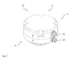
- Fig. 1 shows a movement sensor system 1 according to the invention in a perspective view.
- the first embodiment of the motion sensor system 1 has a first rotation sensor 3 and a second rotation sensor 5.
- the first rotation sensor 3 may have an associated housing part 7 and the second rotation sensor 5 may have an associated housing part 9.
- the housing parts 7 and 9 form a system housing 11.
- the housing part 9 of the second rotary motion sensor 5 may be designed lid-like.
- the housing part 7 has a terminal 13 for a data line (not shown) of the first rotation sensor 3, and the housing part 9 has a terminal 15 for a data line of the second rotary motion sensor 5.
- the separate terminals 13 and 15 allow the data of the rotary motion sensors 3 and 5 to be routed separately from the system housing 11.
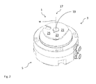
- Fig. 2 shows the motion sensor system 1 Fig. 1 with a view to an axle-side end 17 of a first shaft 19 of the first rotary motion sensor 3.
- the first shaft 19 projects out of the housing part 7 of the first rotary motion sensor 3.
- the first shaft 19 is rotatable about the shaft axis W.
- Rotationally connected to the first shaft 19 is the driven element 21.
- the driven element 21 is used for picking up the rotational movement of the axis of a rail vehicle.
- the axle of the rail vehicle (not shown) may have a drive element which can transmit the movement of the axle to the driven element 21.
- the output element 21 is preferably formed by a driver member 23.
- the output member 21 may be, for example, a part of a transmission, a pickup for a belt or a gear.
- the output element 21 may be formed by any element which is suitable for driving through the axis of the rail vehicle or arranged on the axis of the rail vehicle drive element.
- the driver member 23 is preferably formed as a drive plate 25.
- the driven element 21 or the driver element 23 can be both compact and dimensionally stable at the same time.
- driver members 23 is with reference to the Figures 13 and 14 discussed in more detail.
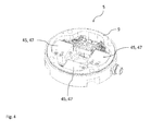
- Fig. 3 shows the first rotation sensor 3 of FIG FIGS. 1 and 2 described first embodiment of the motion sensor system 1 according to the invention without the cover-like housing part 9 of the second rotary motion sensor 5.
- the first shaft 19 protrudes through the first rotary motion sensor 3 and through its associated housing part 7 therethrough.
- the first shaft 19 is rotatably supported in the first rotation sensor 3.
- the first rotary motion sensor 3 can have at least one bearing, in particular a ball bearing.
- a material measure 27 of the first rotation sensor 3 is rotatably arranged on the first shaft 19, a material measure 27 of the first rotation sensor 3 is rotatably arranged.
- the material measure 27 extends radially about the shaft axis W of the first shaft 19.
- the material measure 27 of the first rotation sensor 3 is formed by an incremental disk 29.
- the configuration of the first rotary motion sensor 3 as an incremental rotary encoder 31 is a preferred embodiment of the invention.
- the first rotation sensor 3 may be formed by another rotation sensor.
- the measuring graduation 27 of the first rotary motion sensor 3 need not necessarily be formed by an incremental disk 29.
- sensor components 33 may be housed, which are configured for interrogation and evaluation of the material measure 27.
- the sensor components 33 may be optical detection systems for evaluating the increments of the incremental disk 29.
- the first shaft 19 may be designed so that it projects beyond an upper edge 35 of the housing part 7 also.
- the upper edge 35 is arranged in the direction of the shaft axis W opposite the axle-side end 17.
- the first shaft 19 thus extends beyond the measuring graduation 27 of the first rotary motion sensor 3 at its end opposite the axle-side end 17.
- the first shaft 19 may have at least one further measuring standard 39 of the second rotary motion sensor 5.
- the upper portion 37 of the first shaft 19 has three further measuring graduations 39.
- the further dimensional standards 39 are rotatably connected to the first shaft 19.
- the further measuring graduations 39 of the second rotary motion sensor 5 therefore rotate with the shaft 19 of the first rotary motion sensor 3.
- the torque of the first shaft 19 can be transmitted directly to the measuring graduations 39 of the second rotary motion sensor 5.
- the second rotation sensor 5 is formed according to a preferred embodiment of the invention by a device 41 for detecting rotation in a de-energized state of the rail vehicle.
- the device 41 may be a so-called Cold Movement Detector (CMD).
- CMD Cold Movement Detector
- At least one further measuring standard 39 of the second rotary motion sensor 5 may be formed by a cam disk 43.
- the second rotational movement sensor 5 has three further measuring embodiments 39 formed as a cam disc 43.
- the cams 43 may be crimped and / or pinned to the first shaft 19.
- Fig. 4 shows an interior view of the associated housing part 9 of the second rotational movement sensor 5 of the first embodiment.
- the associated housing part 9 can be designed such that it can be positively inserted into the associated housing part 7 of the first rotary motion sensor 3.
- query elements 45 of the second rotary motion sensor 5 may be arranged.
- the query elements 45 are configured such that they can interrogate or evaluate the material measures 39. If the second rotary motion sensor 5 is a device 41 or a CMD as described, the interrogation elements 45 are preferably formed by bistable actuators 47, which can be deflected by the cams 43, so that rotation of the first shaft 19 can be detected.
- the second rotation sensor 5 is designed so that it can detect a rotational movement of the first shaft 19 when it is not connected to any voltage source. This can be done by an interaction of the cams 43 with the bistable actuators 47. Each cam 43 is associated with a bistable actuator 47. Upon rotation of the first shaft 19, whereby the cams 43 are also rotated, at least one of the cams 43 can move its associated bistable actuator 47 from a first state to a second state. This state can later, as soon as the second rotary motion sensor 5 and / or the rail vehicle are powered again, be read out and compared with a value stored before switching off.
- Fig. 5 and 6 show a second embodiment of a motion sensor system according to the invention 1.
- the housing part 7 of the first rotation sensor 3 has the sensor components 33 of the first rotation sensor 3 and the first shaft 19.
- the first shaft 19 of the second embodiment has no further measuring standard 39 of the second rotary motion sensor 5.
- the first shaft 19 has a first coupling part 49, which is arranged at its end opposite the axle-side end 17.
- the material measure 27 of the first rotary motion sensor 3 extends around the first coupling part 49.
- the first coupling part 49 formed as a parallel to the shaft axis W in the first shaft 19 extending into square-shaped receptacle 51 for receiving a complementarily formed counterpart 53 of the second rotational movement sensor 5.
- the counterpart 53 is part of a shaft 55 of the second rotary motion sensor 5 or connected to a shaft 55 of the second rotary motion sensor 5.
- the counterpart 53 represents the second coupling part 57 of the second rotary motion sensor 5.
- the invention is not limited to the illustrated square shape of the coupling parts 49 and 57. There are also other for the torsionally rigid connection of the first shaft 19 with the second shaft 55 suitable embodiments conceivable.
- the shaft 55 of the second rotary motion sensor 5 may have its own storage 59.
- the bearing 59 may consist of at least one ball bearing.
- the bearing 59 has two ball bearings spaced apart along the shaft axis W, at least one further measuring standard 39 being arranged between the two ball bearings.
- each rotational movement sensor 3 and 5 have in the second embodiment, each rotational movement sensor 3 and 5 a own storage for each own wave 19 and 55 on.
- each rotary motion sensor 3 and 5 is arranged completely in its associated housing part 7 and 9. This allows a quick exchange of the individual rotational movement sensors 3 and 5, if this should be necessary.
- the motion sensor system 1 of the second embodiment has a modular design and has a first sensor module 61 with the first rotary motion sensor 3 and the associated housing part 7 and a second sensor module 63 with the second rotary motion sensor 5 and the associated housing part 9. To connect the two sensor modules 61 and 63, the two sensor modules can be assembled parallel to the shaft axis W, so that the counterpart 53 penetrates into the receptacle 51 and so that the two housing parts 7 and 9 together form a system housing 11.
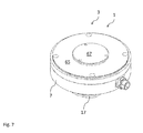
- the Fig. 7 and 8th show a third embodiment of a motion sensor system according to the invention 1.
- the motion sensor system 1, a first Rotary motion sensor 3 according to the second embodiment.
- the housing part 7 is closed at its end which is opposite to the axle-side end 17 of the first shaft 19 with a closure 65.
- This may be advantageous for operating the motion sensor system 1 exclusively with the first rotary motion sensor 3.
- the first rotary motion sensor 3 has a first coupling part 49, it can be subsequently connected to a second rotary motion sensor 5.
- the shutter 65 removed and instead a second rotary motion sensor 5 are set with its associated housing part 9 on the housing part 7, wherein the first shaft 19 of the first rotary motion sensor 3 is connected torsionally rigid with the shaft 55 of the second rotary motion sensor 5.
- the closure 65 may include an additional lid 67 which is removable from the closure 65.
- the cover 67 may be configured such that it conceals the first coupling part 49 of the first shaft 19 in an assembled state.
- the first coupling part 49 may be like the coupling part 49 with Fig. 5 be configured described embodiment.
- the second coupling part 57 of the second rotation sensor 5 (not shown) may be made as described with reference to FIGS Fig. 6 be formed embodiment described.
- the Fig. 9 and 10 show a fourth embodiment of a motion sensor system according to the invention 1.
- an opening 68 of the closure 65 can be closed by a cover 67 (not shown).
- a shaft 55 may be connected to the first shaft 19 without to have their own storage.
- the shaft 55 may have a second coupling part 57, which is rotatably configured with a first coupling part 49 of the first shaft 19 connected.
- the resulting common shaft 69 is then stored only in the first rotary motion sensor 3.
- the second shaft 55 carries at least one further measuring standard 39 of the second rotary motion sensor 5.
- the housing part 9 of the second rotational movement sensor 5, the query elements 45 which can cooperate with the other measuring graduations 39. If the associated housing part 9 of the second rotary motion sensor 5 is placed on the housing part 7 of the first rotary motion sensor 3, then the shaft 55 projects with the measuring graduations 39 into the housing part 9 so that the measuring graduations 39 can cooperate with the interrogation elements 45.
- a motion sensor system with two rotational motion sensors is formed and the housing parts 7 and 9 form a common system housing 11.
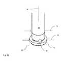
- Fig. 11 merely shows, by way of example, a rotary motion sensor in order to represent the position of the first shaft 19 according to the invention on a rotary motion sensor.
- the arrangement of the first shaft 19 and its axle-side end 17 described below can be used with all previously described embodiments of a motion sensor system according to the invention.
- the first shaft 19 has an axle-side end 17 and extends therefrom along the shaft axis W into the first rotary motion sensor 3.
- the first shaft 19 is connected in a rotationally fixed manner to at least one measuring graduation 27 of the first rotary motion sensor 3.
- the first shaft 19 can be pressed and / or pinned with at least one material measure 27.
- the shaft 19 has a shaft diameter 71.
- the shaft diameter 71 extends over the entire shaft 19 with the exception of its axle-side end 17.
- the shaft 19 has a shaft head 73 with a diameter 75 which is larger than the shaft diameter 71.
- the shaft head 73 can serve this purpose to hold an output member 21 to the shaft 19.
- At least the shaft head 73 can serve to hold an output element 21 in the direction of the axle-side end 17.
- the driven element 21 is pressed onto the first shaft 19.
- the output element 21 may have a receiving opening 77 for the shaft whose diameter 79 corresponds approximately to the shaft diameter 71.
- the shaft diameter 71 may increase towards the shaft head 73, so that the driven element 21 can first slide slightly over the shaft 19 and only then enters into a press connection with the shaft 19 in the region of the shaft head 73 , Due to the press connection between the first shaft 19 and the driven element 21, the driven element 21 can transmit a rotational movement to the first shaft 19 without play.
- the first shaft 19 may have an opening 81 for a positive locking element 83.
- the opening 81 preferably extends continuously through the shaft 19 and perpendicular to the shaft axis W. Also preferably, the opening 81 extends so that it intersects the shaft axis W, that passes centrally through the first shaft 19.
- the opening 81 may also extend at least in sections through the shaft head 73.
- a positive locking element 83 can be used, which can form a positive connection with the driven element 21.
- the output element 21 preferably has at least one bulge 85 which extends away from the receiving opening 77.
- the bulge 85 preferably extends radially from the shaft axis W into the abrasion element 21.
- the driven element 21 preferably has two bulges 85 lying opposite one another. By two opposing bulges 85, an elongated receptacle 87 may be formed for the positive-locking element 83. In Fig.
- a first shaft 19 according to the invention is shown in a sectional view, wherein the cutting plane is shown by an elongate positive-locking element 83 in the shaft 19 and by an elongated receptacle 87 in an output member 21 formed as a driving plate 25.
- the positive locking element 83 can first be inserted into the opening 81 in the first shaft 19 and then the driven element 21 can be pressed onto the first shaft 19 until the driven element 21 bears against the shaft head 73 ,
- the at least one bulge 85 may be arranged so that the form-locking element 83 is arranged in this, when the output element 21 rests against the shaft head 73.
- the output element 21 may be clamped in the mounted state between the shaft head 73 and an inner ring 89 of a bearing 91 of the first rotary motion sensor 3.
- the shaft 19 may be held with the output member 21 so that both elements are still rotatable together about the shaft axis W.
- the output element 21 is formed as a driver member 23.
- the driver member 23 has at least one slot-shaped receptacle 93 for a drive element of the axis of the rail vehicle. In order to keep the driver member 23 compact, it is preferably formed as a drive plate 25.
- the receptacle 93 for a drive element then preferably extends radially to the shaft axis W into the driver disk 25.
- Fig. 14 shows a second embodiment of a drive plate according to the invention 25.
- the receptacle 93 for a drive element of the axle of the rail vehicle is bounded by two elastically deflectable tongues 95.
- the drive plate 25 has two indentations 97 extending parallel to the slot-shaped receptacle 93 into the drive plate.
- the tongues 95 are then bounded by the receptacle 93 and the recesses 97. Free ends 99 of the tongues 95 are deflectable into the indentations 97.
- the tongues 95 are deflectable within a disc plane E of the drive plate 25.
- the receptacle 93 has a receiving diameter 101.
- the receiving diameter 101 is measured perpendicular to the rectilinear tongues 95.
- the receiving diameter 101 is preferably smaller than a diameter of a drive element of the axis of the rail vehicle. If a drive element is inserted into the receptacle 93, the tongues 95 are elastically deflected, since the drive element has a larger diameter than receptacle 93. In this way, a drive element can be held without play in the receptacle 93.
Abstract
Die Erfindung betrifft ein Bewegungssensorsystem (1) zur Montage an der Achse eines Schienenfahrzeugs, mit wenigstens einer durch die Achse des Schienenfahrzeugs drehbaren ersten Welle (19) und mit wenigstens einer mit der ersten Welle (19) drehfest verbundenen Maßverkörperung (27) eines ersten Drehbewegungssensors (3), wobei die erste Welle (19) ein Abtriebselement (21) zum Abgreifen der Bewegung der Achse aufweist. Um ein Bewegungssensorsystem (1) bereitzustellen, das eine hohe Flexibilität aufweist, das die Erfassung verschiedener Parameter ermöglichen kann, und das kompakt ist, ist erfindungsgemäß vorgesehen, dass die erste Welle (19) zur Übertragung eines Drehmoments an einen zweiten Drehbewegungssensor (5) ausgestaltet ist. Mit Hilfe eines Kupplungsteils an der ersten Welle kann eine Verbindung zu einer Welle des zweiten Drehbewegungssensors hergestellt werden. Alternativ kann eine Maßverkörperung des zweiten Drehbewegungssensors auf die erste Welle aufgebracht werden. Die Anmeldung gestattet eine modulare Ausgestaltung eines solchen Sensorsystems, bei der bei Bedarf einzelne Komponenten ausgetauscht oder weggelassen werden können.The invention relates to a motion sensor system (1) for mounting on the axle of a rail vehicle, comprising at least one first shaft (19) rotatable by the axis of the rail vehicle and at least one measuring standard (27) of a first rotational motion sensor rotatably connected to the first shaft (19) (3), wherein the first shaft (19) has an output member (21) for sensing the movement of the axle. In order to provide a motion sensor system (1) which has a high flexibility, which can allow the detection of various parameters, and which is compact, it is provided according to the invention that the first shaft (19) designed to transmit a torque to a second rotation sensor (5) is. By means of a coupling part on the first shaft, a connection can be made to a shaft of the second rotary motion sensor. Alternatively, a material measure of the second rotation sensor can be applied to the first shaft. The application allows a modular design of such a sensor system in which individual components can be replaced or omitted if necessary.
Description
Die Erfindung betrifft ein Bewegungssensorsystem zur Montage an der Achse eines Schienenfahrzeugs, mit wenigstens einer durch die Achse des Schienenfahrzeugs drehbaren ersten Welle und mit wenigstens einer mit der ersten Welle drehfest verbundenen Maßverkörperung eines ersten Drehbewegungssensors, wobei die erste Welle ein Abtriebselement zum Abgreifen der Bewegung der Achse aufweist. Die Erfindung betrifft zudem eine Achse für ein Schienenfahrzeug.The invention relates to a motion sensor system for mounting on the axle of a rail vehicle, comprising at least one first shaft rotatable by the axis of the rail vehicle and having at least one dimensional standard of a first rotation sensor rotatably connected to the first shaft, wherein the first shaft is an output element for tapping the movement of Has axis. The invention also relates to an axle for a rail vehicle.
Bewegungssensorsysteme sind wichtige Bestandteile von modernen Schienenfahrzeugen. Bewegungssensorsysteme können eingesetzt werden, um Drehungen der Achsen von Schienenfahrzeugen zu detektieren, zu analysieren und zu kontrollieren. Bekannte Drehbewegungssensoren werden häufig so an feststehenden Teilen des Schienenfahrzeugs befestigt, dass die Achse des Schienenfahrzeugs ihre Drehbewegung an die Welle des Drehbewegungssensors übertragen kann. Nachteilig bei den bekannten Drehbewegungssensoren ist jedoch, dass diese häufig jeweils nur Informationen über einzelne Parameter der Drehbewegung der Achse des Schienenfahrzeugs liefern können. Zudem weisen bekannte Drehbewegungssensoren ein großes Volumen auf.Motion sensor systems are important components of modern rail vehicles. Motion sensor systems can be used to detect, analyze, and control rotations of the axles of rail vehicles. Known rotational motion sensors are often mounted to stationary parts of the rail vehicle such that the axle of the rail vehicle can transmit its rotational motion to the shaft of the rotary motion sensor. A disadvantage of the known rotational motion sensors, however, is that they can often only provide information about individual parameters of the rotational movement of the axle of the rail vehicle. In addition, known rotational motion sensors have a large volume.
Es ist daher Aufgabe der Erfindung, ein Bewegungssensorsystem der oben genannten Art bereitzustellen, das zur umfassenderen Analyse der Drehbewegung der Achse des Schienenfahrzeugs ausgestaltet ist, das kompakt ist und das zudem eine sichere Übertragung der Drehbewegung der Achse des Schienenfahrzeugs wenigstens auf die Maßverkörperung des ersten Drehbewegungssensors ermöglicht.It is therefore an object of the invention to provide a motion sensor system of the type mentioned above, which is designed for more comprehensive analysis of the rotational movement of the axis of the rail vehicle, which is compact and also a safe transmission of the rotational movement of the axis of the rail vehicle at least on the material measure of the first rotational motion sensor allows.
Diese Aufgabe ist für ein Bewegungssensorsystem der oben genannten Art erfindungsgemäß dadurch gelöst, dass die erste Welle zur Übertragung eines Drehmoments an einen zweiten Drehbewegungssensor ausgestaltet ist.This object is achieved according to the invention for a motion sensor system of the type mentioned above in that the first shaft is designed to transmit a torque to a second rotary motion sensor.
Die erfindungsgemäße Lösung erlaubt es, einen zweiten Drehbewegungssensor mit dem ersten Drehbewegungssensor zu koppeln. Dadurch kann ein Bewegungssensorsystem aus zwei Drehbewegungssensoren gebildet sein, wovon jeder Drehbewegungssensor jeweils für die Erfassung unterschiedlicher Parameter ausgestaltet sein kann. Da ein zweiter Drehbewegungssensor das Drehmoment von der ersten Welle übertragen bekommt, kann das Bewegungssensorsystem sehr kompakt aufgebaut sein und zudem an einem Ende der Achse des Schienenfahrzeugs angebracht sein. So können an einem Achsende verschiedene Parameter abgegriffen werden.The solution according to the invention makes it possible to couple a second rotary motion sensor to the first rotary motion sensor. As a result, a motion sensor system can be formed from two rotational motion sensors, of which each rotational motion sensor can each be designed to detect different parameters. Since a second rotation sensor gets the torque transmitted from the first shaft, the motion sensor system can be made very compact and also be attached to one end of the axle of the rail vehicle. This means that different parameters can be tapped at one axis end.
Die genannten Drehbewegungssensoren können jeweils aus einer zugehörigen Maßverkörperung und wenigstens einem dazugehörigen Abfrageelement bestehen. Zusätzlich können die Drehbewegungssensoren Sensorkomponenten wie Auswerte- bzw. Steuereinheiten aufweisen. Die Übertragung des Drehmoments bzw. der Drehbewegung an den zweiten Drehbewegungssensor kann an einem Ende der ersten Welle erfolgen, welches in Achsrichtung der Welle gegenüber dem Abtriebselement liegt.The rotational motion sensors mentioned can each consist of an associated material measure and at least one associated query element. In addition, the rotational motion sensors may include sensor components such as evaluation or control units. The transmission of the torque or the rotational movement to the second rotary motion sensor can take place at one end of the first shaft, which lies in the axial direction of the shaft relative to the output element.
Für die eingangs genannte Achse für ein Schienenfahrzeug ist die erfindungsgemäße Aufgabe dadurch gelöst, dass die Achse an einem Achsende ein erfindungsgemäßes Bewegungssensorsystem aufweist. Die Achse des Schienenfahrzeugs muss dadurch nur an einem Achsende zur Übertragung ihres Drehmoments an ein Bewegungssensorsystem ausgestaltet sein. Dadurch können Kosten gespart werden.For the aforementioned axle for a rail vehicle, the object according to the invention is achieved in that the axle has an inventive motion sensor system at one axle end. As a result, the axle of the rail vehicle only has to be configured at one axle end for transmitting its torque to a motion sensor system. This can save costs.
Die erfindungsgemäße Lösung kann durch verschiedene, jeweils für sich vorteilhafte und beliebig miteinander kombinierbare Ausgestaltungen weiter verbessert werden. Auf diese Ausgestaltungsformen und die mit ihnen verbundenen Vorteile ist im Folgenden eingegangen.The solution according to the invention can be further improved by various configurations which are advantageous in each case and can be combined with one another as desired. These embodiments and the advantages associated with them are discussed below.
Gemäß einer ersten vorteilhaften Ausgestaltung eines erfindungsgemäßen Bewegungssensorsystems kann das Abtriebselement durch ein sich an einem achsseitigen Ende der ersten Welle befindliche Mitnehmerorgan gebildet sein. Das Mitnehmerorgan kann dazu ausgestaltet sein, die Bewegung der Achse des Schienenfahrzeugs abzugreifen und auf die Welle zu übertragen. Insbesondere kann das Mitnehmerorgan mit einem Antriebselement der Achse des Schienenfahrzeugs in Eingriff stehen, wenn das Bewegungssensorsystem an der Achse montiert ist. Das Mitnehmerorgan kann insbesondere durch eine Mitnehmerscheibe gebildet sein, wobei eine Scheibenebene senkrecht zur Wellenachse angeordnet ist.According to a first advantageous embodiment of a motion sensor system according to the invention, the output element may be formed by a located on an axle-side end of the first shaft driver member. The driver member may be configured to pick up the movement of the axle of the rail vehicle and transfer it to the shaft. In particular, the cam member may be engaged with a drive member of the axle of the rail vehicle when the motion sensor system is mounted on the axle. The driver member may be formed in particular by a driver disk, wherein a disk plane is arranged perpendicular to the shaft axis.
Um eine besonders sichere Verbindung zwischen dem Mitnehmerorgan und der ersten Welle zu erhalten, kann das Mitnehmerorgan mit dem achsseitigen Ende der ersten Welle verpresst sein. Diese Art der Verbindung ist zudem kostengünstig herstellbar. Das Mitnehmerorgan, insbesondere eine Mitnehmerscheibe kann dazu eine Aufnahmeöffnung aufweisen, durch die die Welle im verpressten Zustand ragt. Ist das Mitnehmerorgan durch eine Mitnehmerscheibe gebildet, so weist die Mitnehmerscheibe bevorzugt in ihrem Zentrum eine Aufnahmeöffnung für die Welle auf. Die Welle kann zum Sichern des Mitnehmerorgans an ihrem achsseitigen Ende einen Wellenkopf aufweisen, dessen Durchmesser größer als ein Durchmesser der Aufnahmeöffnung des Mitnehmerorgans ist. Die sichere, drehsteife Verbindung zwischen der ersten Welle und dem Abtriebselement bzw. der Mitnehmerscheibe ist insbesondere dann von großer Bedeutung, wenn das Bewegungssensorsystem zwei Drehbewegungssensoren aufweist, da beide Drehbewegungssensoren die Drehung der Achse des Schienenfahrzeugs über das Abtriebselement von der ersten Welle abgreifen.In order to obtain a particularly secure connection between the entrainment member and the first shaft, the entrainment member may be crimped with the axle-side end of the first shaft. This type of connection is also inexpensive to produce. The entrainment member, in particular a drive plate, can for this purpose have a receiving opening, through which the shaft protrudes in the compressed state. If the driver member is formed by a driver disk, the driver disk preferably has a receiving opening for the shaft in its center. The shaft can be used to back up the Mitnehmerorgans have at their achseititigen end a shaft head whose diameter is greater than a diameter of the receiving opening of the driver member. The safe, torsionally rigid connection between the first shaft and the output element or the drive plate is particularly important if the motion sensor system has two rotational motion sensors, since both rotational motion sensors pick up the rotation of the axis of the rail vehicle via the output element of the first shaft.
Um die Verbindung zwischen dem Abriebselement und der ersten Welle weiter zu verbessern, kann das Abtriebselement eine Aufnahmeöffnung für die erste Welle mit wenigstens einer Ausbuchtung für wenigstens ein Formschlusselement aufweisen. Insbesondere wenn das Abtriebselement bzw. ein das Abtriebselement bildendes Mitnehmerorgan mit dem achsseitigen Ende der ersten Welle verpresst ist, kann ein in der Ausbuchtung befindliches Formschlusselement der ersten Welle dafür sorgen, dass die Drehbewegung des Abtriebselements auch auf die Welle übertragen wird, wenn die Pressverbindung zwischen dem Abtriebselement und der ersten Welle gelöst oder gelockert sein sollte. Ist das Abtriebselement durch eine Mitnehmerscheibe gebildet, so erstreckt sich die wenigstens eine Ausbuchtung bevorzugt radial von der Aufnahmeöffnung für die erste Welle in die Mitnehmerscheibe hinein. Bevorzugt weist das Abtriebselement zwei sich gegenüber liegende Ausbuchtungen auf, welche zusammen eine längliche Aufnahme für ein längliches Formschlusselement bilden können.In order to further improve the connection between the abrading element and the first shaft, the output element may have a receiving opening for the first shaft with at least one bulge for at least one positive-locking element. In particular, when the output member or a drive member forming the output member is crimped with the axle end of the first shaft, located in the bulge positive locking element of the first shaft can ensure that the rotational movement of the output element is also transmitted to the shaft when the press connection between the output element and the first shaft should be loosened or loosened. If the output element is formed by a driver disk, the at least one projection preferably extends radially from the receiving opening for the first shaft into the driver disk. The output element preferably has two bulges lying opposite one another, which together can form an elongate receptacle for an elongate positive-locking element.
Das Formschlusselement kann insbesondere stiftförmig sein. Das Formschlusselement ragt bevorzugt am achsseitigen Wellenende durch die erste Welle. Alternativ dazu kann es auch monolithisch mit der ersten Welle gebildet sein oder außen an dieser angebracht sein. Damit das Formschlusselement durch die erste Welle ragen kann, kann die erste Welle eine durchgängige Öffnung für das Formschlusselement quer zur Wellenachse aufweisen. Bevorzugt erstreckt sich die durchgängige Öffnung für das Formschlusselement durch die Achsmitte der ersten Welle.The form-fitting element may in particular be pin-shaped. The positive-locking element preferably projects on the axle-side shaft end through the first shaft. Alternatively, it may also be formed monolithically with the first shaft or attached externally to this. So that the interlocking element can protrude through the first shaft, the first shaft can have a continuous opening for the interlocking element transversely to the shaft axis. The continuous opening for the interlocking element preferably extends through the axial center of the first shaft.
Die Ausbuchtung für das wenigstens eine Formschlusselement im Abtriebselement erstreckt sich bevorzugt parallel zur Achsrichtung der Welle durchgängig durch das Abtriebselement hindurch. Im Falle einer Mitnehmerscheibe erstreckt sich die wenigstens eine Ausbuchtung also axial durch die Mitnehmerscheibe durch und radial in diese hinein.The bulge for the at least one interlocking element in the driven element preferably extends parallel to the axial direction of the shaft through the driven element. In the case of a drive plate, the at least one bulge thus extends axially through the drive plate and radially into it.
Bevorzugt grenzt die durchgängige Öffnung für das Formschlusselement in der ersten Welle an den Kopf am achsseitigen Wellenende an. Die durchgängige Öffnung kann sich auch zumindest abschnittsweise durch den Kopf hindurch erstrecken. Es ist anzumerken, dass die Öffnung für das Formschlusselement nicht zwangsläufig eine durchgängige Öffnung sein muss. Insbesondere kann die erste Welle auch eine oder mehrere Öffnungen aufweisen, welche sich radial in das Wellenende erstrecken, um jeweils ein Formschlusselement aufzunehmen.The continuous opening for the positive-locking element in the first shaft preferably adjoins the head on the axle-side shaft end. The continuous opening can be extend at least partially through the head. It should be noted that the opening for the positive-locking element does not necessarily have to be a continuous opening. In particular, the first shaft may also have one or more openings, which extend radially into the shaft end, to receive in each case a positive-locking element.
Zur Montage einer bevorzugten Ausführungsform mit einer durchgängigen Öffnung für das Formschlusselement im Wellenende wird zunächst ein längliches Formschlusselement in die durchgängige Öffnung eingesetzt und dann das Abtriebselement, welches bevorzugt durch eine Mitnehmerscheibe gebildet ist, auf die Welle gepresst, bis das Abtriebselement am Kopf der Welle anliegt und dabei das Formschlusselement in der wenigstens einen Ausbuchtung aufgenommen ist.For mounting a preferred embodiment with a continuous opening for the interlocking element in the shaft end, an elongate positive locking element is first inserted into the continuous opening and then the driven element, which is preferably formed by a drive plate, pressed onto the shaft until the output element rests against the head of the shaft and while the positive-locking element is received in the at least one bulge.
Das Abtriebselement, insbesondere eine Mitnehmerscheibe kann zur besonders sicheren Befestigung alternativ oder zusätzlich zu der zuvor beschriebenen Verbindung mit dem Formschlusselement zwischen dem Kopf der Welle und einem Kugellagerinnenring des ersten Drehbewegungssensors angeordnet sein. Dabei kann durch eine geeignete Befestigungsmaßnahme im ersten Drehbewegungssensor ein Zug auf die Welle ausgeübt werden, so dass die Mitnehmerscheibe zwischen dem Kopf der Welle und dem genannten Kugellagerinnenring eingepresst ist. Durch das Kugellager kann die Mitnehmerscheibe dabei um die Wellenachse drehbar sein.The output element, in particular a drive plate can be arranged for particularly secure attachment alternatively or additionally to the previously described connection with the form-fitting element between the head of the shaft and a ball bearing inner ring of the first rotation sensor. In this case, a train can be exerted on the shaft by a suitable fastening measure in the first rotary motion sensor, so that the drive plate is pressed between the head of the shaft and said ball bearing inner ring. Through the ball bearing, the drive plate can be rotatable about the shaft axis.
Gemäß einer weiteren vorteilhaften Ausgestaltung kann das Abtriebselement wenigstens einen quer zur Wellenachse verlaufenden Aufnahmeschlitz zur Aufnahme eines Antriebselements der Achse des Schienenfahrzeugs aufweisen, wobei der wenigstens eine Aufnahmeschlitz zumindest an einer Seite von einer elastisch auslenkbaren Zunge begrenzt ist. Dabei kann der Aufnahmeschlitz so gewählt sein, dass sein Aufnahmedurchmesser höchstens dem Durchmesser des Antriebselements entspricht. Bevorzugt weist der Aufnahmeschlitz ohne ein in ihm aufgenommenes Antriebselement einen Aufnahmedurchmesser auf, welcher geringer als ein Durchmesser des Antriebselements ist. Beim Einsetzen des Antriebselements in den Aufnahmeschlitz wird dann die wenigstens eine elastisch auslenkbare Zunge elastisch vom Aufnahmeschlitz weg ausgelenkt und übt einen Druck auf das Antriebselement aus. Dadurch kann das Antriebselement spielfrei im Aufnahmeschlitz aufgenommen sein.According to a further advantageous embodiment, the output member may comprise at least one receiving slot extending transversely to the shaft axis for receiving a drive element of the axis of the rail vehicle, wherein the at least one receiving slot is bounded on at least one side by an elastically deflectable tongue. In this case, the receiving slot can be selected so that its receiving diameter corresponds at most to the diameter of the drive element. Preferably, the receiving slot without a drive element received in it has a receiving diameter, which is smaller than a diameter of the drive element. When inserting the drive element in the receiving slot then the at least one elastically deflectable tongue is elastically deflected away from the receiving slot and exerts a pressure on the drive element. As a result, the drive element can be accommodated without play in the receiving slot.
Um ein besonders einfach aufgebautes und kompaktes Bewegungssensorsystem zu erhalten, kann die erste Welle mit wenigstens einer weiteren Maßverkörperung des zweiten Drehbewegungssensors versehen sein. Die erste Welle überträgt dann das Drehmoment bzw. die Drehbewegung der Achse des Schienenfahrzeugs durch diese Maßnahme direkt auf wenigstens eine Maßverkörperung des zweiten Drehbewegungssensors.To obtain a particularly simple and compact motion sensor system, the first shaft with at least one further material measure of the be provided second rotary motion sensor. The first shaft then transmits the torque or the rotational movement of the axis of the rail vehicle by this measure directly to at least one material measure of the second rotational movement sensor.
Die erste Welle kann ein erstes Kupplungsteil zur drehsteifen Verbindung mit einem zweiten Kupplungsteil einer Welle des zweiten Drehbewegungssensors aufweisen. Dadurch kann das Bewegungssensorsystem modular aufgebaut sein. Dies kann von Vorteil sein, um die erste Welle des ersten Drehbewegungssensors und die Welle des zweiten Drehbewegungssensors getrennt voneinander herzustellen. Ein weiterer Vorteil kann der sein, dass ein Bewegungssensorsystem zunächst nur mit einem ersten Drehbewegungssensor an einer Achse des Schienenfahrzeugs montiert wird, solange nur die von diesem ersten Drehbewegungssensor erfassten Parameter aufgenommen werden sollen. Sollen zu einem späteren Zeitpunkt weitere Parameter erfasst werden, so kann über die Kupplung an der ersten Welle des ersten Drehbewegungssensors eine Welle des zweiten Drehbewegungssensors angebracht werden, so dass das Bewegungssensorsystem zwei Drehbewegungssensoren nutzen kann.The first shaft may have a first coupling part for the torsionally rigid connection with a second coupling part of a shaft of the second rotary motion sensor. As a result, the motion sensor system can be modular. This may be advantageous for making the first shaft of the first rotation sensor and the shaft of the second rotation sensor separate from each other. Another advantage may be that a motion sensor system is first mounted on an axle of the rail vehicle only with a first rotational motion sensor as long as only the parameters detected by that first rotary motion sensor are to be recorded. If further parameters are to be detected at a later time, a shaft of the second rotational motion sensor can be attached via the coupling to the first shaft of the first rotational motion sensor, so that the motion sensor system can use two rotational motion sensors.
Die Kupplung zwischen dem ersten Kupplungsteil und dem zweiten Kupplungsteil ist bevorzugt formschlüssig. Insbesondere kann das erste Kupplungsteil mit dem zweiten Kupplungsteil in einem gekuppelten Zustand ineinander greifen. Alternativ dazu sind jedoch auch andere Kupplungsvarianten möglich. Beispielsweise kann eine Kupplung zwischen dem ersten Kupplungsteil und dem zweiten Kupplungsteil auch reibschlüssig oder magnetisch erfolgen.The coupling between the first coupling part and the second coupling part is preferably form-fitting. In particular, the first coupling part can engage with the second coupling part in a coupled state. Alternatively, however, other coupling variants are possible. For example, a coupling between the first coupling part and the second coupling part can also be frictional or magnetic.
Um die Montage zu vereinfachen, kann das erste Kupplungsteil mit dem zweiten Kupplungsteil entlang der Achsrichtung der ersten Welle zusammenschieb- oder zusammensteckbar sein.To simplify the assembly, the first coupling part with the second coupling part along the axial direction of the first shaft can be pushed together or plugged together.
Der erste Drehbewegungssensor kann durch einen Inkrementaldrehgeber gebildet sein. Ein Inkrementaldrehgeber kann dazu genutzt werden, die Rotationsgeschwindigkeit der Achse des Schienenfahrzeugs mit hoher Genauigkeit zu bestimmen.The first rotation sensor may be formed by an incremental encoder. An incremental encoder can be used to determine the rotational speed of the axis of the rail vehicle with high accuracy.
Der Inkrementaldrehgeber kann zur Ausgabe eines Rolliersignals ausgestaltet sein. Rolliersignale können Aussagen über ein Rollieren der Achse liefern, welches es zu vermeiden gilt. Ein Inkrementaldrehgeber, welcher ein Rolliersignal ausgeben kann, kann wesentlich für einen sicheren Betrieb eines Schienenfahrzeugs sein.The incremental rotary encoder can be designed to output a rolling signal. Rolling signals can provide information about a rolling of the axle, which should be avoided. An incremental encoder which can output a rolling signal can be essential for the safe operation of a rail vehicle.
Um den ersten Drehbewegungssensor als Inkrementaldrehgeber zu verwenden, kann die Maßverkörperung des ersten Drehbewegungssensors durch eine Inkrementscheibe gebildet sein. Die Inkrementscheibe kann insbesondere drehfest auf der ersten Welle angeordnet sein. Die Inkrementscheibe kann auf die erste Welle gepresst sein und/oder durch eine Verstiftung formschlüssig mit der ersten Welle verbunden sein.In order to use the first rotary motion sensor as an incremental rotary encoder, the measuring graduation of the first rotary motion sensor can be formed by an incremental disk. The incremental disc can be arranged in particular rotationally fixed on the first shaft. The incremental disk can be pressed onto the first shaft and / or can be positively connected to the first shaft by pinning.
Der zweite Drehbewegungssensor kann durch eine Vorrichtung zur Erfassung einer Drehung der Achse des Schienenfahrzeugs in einem stromlosen Zustand des Schienenfahrzeugs gebildet sein. Insbesondere kann der zweite Drehbewegungssensor ein Cold-Movement-Detektor (CMD) sein. Mit diesem ist es möglich, eine Drehung der Achse des Schienenfahrzeugs festzustellen, auch wenn sich das Schienenfahrzeug in einem abgerüsteten und damit stromlosen Zustand befindet.The second rotation sensor may be constituted by a device for detecting rotation of the axis of the rail vehicle in a de-energized state of the rail vehicle. In particular, the second rotary motion sensor may be a cold movement detector (CMD). With this it is possible to detect a rotation of the axis of the rail vehicle, even if the rail vehicle is in a disarmed and therefore de-energized state.
Ein Bewegungssensorsystem, bei dem der erste Drehbewegungssensor ein Inkrementaldrehgeber, insbesondere ein solcher mit integrierter Rolliererkennung, und der zweite Drehbewegungssensor ein Cold-Movement-Detektor ist, ist besonders vorteilhaft, da mit einem solchen Bewegungssensorsystem wichtige sicherheitsrelevante Parameter erfasst werden können. Der erste Drehbewegungssensor kann beispielsweise während des Betriebs des Schienenfahrzeugs die Geschwindigkeit der Achse und ein eventuell auftretendes Rollieren derselben erfassen und der zweite Drehbewegungssensor kann dazu dienen, eine Bewegung der Achse in einem stromlosen Zustand des Schienenfahrzeugs zu erkennen. Da die beiden Drehbewegungssensoren ein Bewegungssensorsystem bilden und an einem Achsende des Schienenfahrzeugs angeordnet sein können, ist ein kompaktes Bewegungssensorsystem gegeben, durch das es möglich ist, die zuvor genannten Parameter an einem Achsende zu erzeugen.A motion sensor system in which the first rotary motion sensor is an incremental rotary encoder, in particular one with integrated roller burn detection, and the second rotary motion sensor is a cold movement detector, is particularly advantageous since important safety-relevant parameters can be detected with such a motion sensor system. For example, during operation of the rail vehicle, the first rotary motion sensor may sense the speed of the axle and any rolling thereof, and the second rotary motion sensor may serve to detect movement of the axle in a de-energized state of the rail vehicle. Since the two rotary motion sensors form a motion sensor system and can be arranged at an axle end of the rail vehicle, a compact motion sensor system is provided, by means of which it is possible to generate the aforementioned parameters at an axle end.
Um sicherzustellen, dass eine Bewegung des Schienenfahrzeugs auch im abgerüsteten Zustand desselben erfasst wird, kann der zweite Drehbewegungssensor dazu ausgestaltet sein, eine Bewegung der Achse des Schienenfahrzeugs zu erfassen, selbst wenn der zweite Drehbewegungssensor selbst stromlos ist. Dies kann beispielsweise dadurch erreicht werden, dass die Maßverkörperung des zweiten Drehbewegungssensors durch eine Nockenscheibe gebildet ist und der zweite Drehbewegungssensor bistabile Aktoren aufweist, welche durch die Nockenscheibe bei einer Drehung der Welle von einem Zustand in einen zweiten Zustand versetzt werden können. Dies kann auch im stromlosen Zustand des Drehbewegungssensors selbst geschehen, wobei der Zustand der Aktoren von einer Auswerteeinheit ausgelesen werden kann, sobald wenigstens der zweite Drehbewegungssensor wieder mit einer Spannungsquelle verbunden ist.In order to ensure that a movement of the rail vehicle is detected even in the disarmed state thereof, the second rotation sensor may be configured to detect a movement of the axis of the rail vehicle, even if the second rotation sensor itself is de-energized. This can be achieved, for example, in that the dimensional standard of the second rotary motion sensor is formed by a cam disk and the second rotary motion sensor has bistable actuators which can be displaced from a state to a second state by the cam disk upon rotation of the shaft. This can also be done in the de-energized state of the rotary motion sensor itself, wherein the state of the actuators can be read by an evaluation unit as soon as at least the second rotary motion sensor is again connected to a voltage source.
Um ein Bewegungssensorsystem mit zwei Drehbewegungssensoren besonders kompakt zu gestalten und um eine sichere Übertragung des Drehmoments bis auf wenigstens eine Maßverkörperung des zweiten Drehbewegungssensors zu erreichen, kann wenigstens eine Maßverkörperung des zweiten Drehbewegungssensors auf der ersten Welle angeordnet sein. Dadurch kann die erste Welle eine gemeinsame Welle für den ersten und den zweiten Drehbewegungssensor darstellen. Alternativ dazu ist es auch möglich, dass wenigstens eine Maßverkörperung des zweiten Drehbewegungssensors auf der ersten Welle angeordnet ist, diese Welle jedoch trotzdem über eine Kupplung mit einer zweiten Welle verbunden ist, auf der wenigstens eine weitere Maßverkörperung des zweiten Drehbewegungssensors angeordnet ist.In order to make a motion sensor system with two rotational motion sensors particularly compact and to achieve reliable transmission of the torque to at least one material measure of the second rotational motion sensor, at least one dimensional standard of the second rotational motion sensor can be arranged on the first shaft. Thereby, the first shaft may constitute a common shaft for the first and second rotational motion sensors. Alternatively, it is also possible for at least one material measure of the second rotation sensor to be arranged on the first shaft, but this shaft is nevertheless connected via a coupling to a second shaft, on which at least one further dimensional standard of the second rotation sensor is arranged.
In einem montierten Zustand kann je ein Drehbewegungssensor wenigstens abschnittsweise in einem zugehörigen Gehäuseteil angeordnet sein. Dadurch können die einzelnen Drehbewegungssensoren entsprechend ihrer Abmessungen und technischen Voraussetzungen gegen äußere Einflüsse geschützt sein. Dabei ist es besonders vorteilhaft, wenn die Gehäuseteile zu einem gemeinsamen Systemgehäuse des Bewegungssensorsystems zusammensetzbar sind. Ebenfalls von Vorteil ist es, wenn die Gehäuseteile parallel zur Achsrichtung der ersten Welle des ersten Drehbewegungssensors zusammensetzbar sind. Dadurch kann es ermöglicht sein, ein Gehäuseteil des zweiten Drehbewegungssensors auf das Gehäuseteil des ersten Drehbewegungssensors zu montieren und dabei gleichzeitig eine zweite Welle des zweiten Drehbewegungssensors mit der ersten Welle des ersten Drehbewegungssensors zu verbinden, oder die erste Welle des Drehbewegungssensors mit einer Maßverkörperung des zweiten Drehbewegungssensors in das Gehäuseteil des zweiten Drehbewegungssensors einzuführen.In a mounted state, a rotary motion sensor can each be arranged at least in sections in an associated housing part. As a result, the individual rotary motion sensors can be protected against external influences in accordance with their dimensions and technical requirements. It is particularly advantageous if the housing parts can be assembled to form a common system housing of the motion sensor system. It is also advantageous if the housing parts can be assembled parallel to the axial direction of the first shaft of the first rotary motion sensor. As a result, it may be possible to mount a housing part of the second rotary motion sensor on the housing part of the first rotary motion sensor and simultaneously to connect a second shaft of the second rotary motion sensor to the first shaft of the first rotary motion sensor, or the first shaft of the rotary motion sensor to a material measure of the second rotary motion sensor to insert into the housing part of the second rotation sensor.
Gemäß einer weiteren vorteilhaften Ausgestaltung kann wenigstens ein Drehbewegungssensor mit seinem zugehörigen Gehäuseteil ein austauschbares Sensormodul bilden. D.h. jedes Sensormodul weist einen Drehbewegungssensor und das dazugehörige Gehäuseteil auf. Dadurch kann ein Bewegungssensorsystem modular aufgebaut sein und es können einzelne Teile bzw. einzelne Sensormodule beispielsweise in einem Schadenfall einfach ausgetauscht werden. Bevorzugt weisen die austauschbaren Sensormodule jeweils eigene Wellen mit Kupplungsteilen auf, so dass durch eine Verbindung zweier Sensormodule auch die Wellen der Drehbewegungssensoren drehfest miteinander verbunden werden. Dabei können die Wellen jeweils in ihren Sensormodulen bzw. in ihren Gehäuseteilen gelagert sein, d.h. jede Welle verfügt über eine Eigenlagerung. Alternativ dazu kann auch nur die erste Welle eine Eigenlagerung aufweisen. Die Welle des zweiten Drehbewegungssensors kann ohne eigene Lagerung ausgestaltet sein und als Verlängerung der ersten Welle deren Lagerung nutzen.According to a further advantageous embodiment, at least one rotary motion sensor with its associated housing part form an exchangeable sensor module. This means that each sensor module has a rotary motion sensor and the associated housing part. As a result, a motion sensor system can be modular and individual parts or individual sensor modules can be easily exchanged, for example, in the event of a damage. Preferably, the exchangeable sensor modules each have their own shafts with coupling parts, so that by a connection of two sensor modules and the waves of the rotary motion sensors are rotatably connected to each other. In this case, the shafts can each be mounted in their sensor modules or in their housing parts, ie each shaft has an integral bearing. Alternatively, only the first wave can be used have a self-storage. The shaft of the second rotary motion sensor can be configured without own storage and use as an extension of the first wave their storage.
Um die Sicherheit für ein Schienenfahrzeug zu erhöhen und um zu gewährleisten, dass beim Ausfall eines Drehbewegungssensors die Funktion des anderen Drehbewegungssensors nicht beeinträchtigt ist, kann jeder Drehbewegungssensor eine eigene Datenleitung zur Übertragung von Sensorsignalen an wenigstens eine Kontrolleinrichtung aufweisen. Dabei kann die Kontrolleinrichtung entweder ein Bestandteil des Bewegungssensorsystems sein, oder ein externes System darstellen.In order to increase the safety of a rail vehicle and to ensure that the function of the other rotational motion sensor is not impaired in the event of failure of a rotary motion sensor, each rotary motion sensor may have its own data line for transmitting sensor signals to at least one control device. In this case, the control device can either be a component of the motion sensor system, or represent an external system.
Um eine Modularität der Drehbewegungssensoren des Bewegungssensorsystems zu verbessern, kann jedes Gehäuseteil wenigstens einen Anschluss für eine Datenleitung des zugehörigen Drehbewegungssensors aufweisen.In order to improve a modularity of the rotational motion sensors of the motion sensor system, each housing part may have at least one connection for a data line of the associated rotational motion sensor.
Im Folgenden ist die Erfindung beispielhaft anhand vorteilhafter Ausführungsformen mit Bezug auf die Zeichnungen näher erläutert. Die bei den Ausführungsformen beispielhaft dargestellten Merkmalskombinationen können nach Maßgabe der obigen Ausführungen entsprechend für einen bestimmten Anwendungsfall durch weitere Merkmale ergänzt werden. Auch können, ebenfalls nach Maßgabe der obigen Ausführungen, einzelne Merkmale bei den beschriebenen Ausführungsformen weggelassen werden, wenn es auf die Wirkung dieses Merkmals in einem konkreten Anwendungsfall nicht ankommt.The invention is explained in more detail below by way of example with reference to advantageous embodiments with reference to the drawings. The feature combinations exemplified in the embodiments can be supplemented according to the above statements accordingly for a particular application by further features. Also, also in accordance with the above statements, individual features may be omitted in the described embodiments, if the effect of this feature in a specific application does not matter.
In den Zeichnungen werden für Elemente gleicher Funktion und/oder gleichen Aufbaus stets dieselben Bezugszeichen verwendet.In the drawings, the same reference numerals are always used for elements of the same function and / or same structure.
Es zeigen:
- Fig. 1
- eine perspektivische Darstellung einer ersten Ausführungsform eines erfindungsgemäßen Bewegungssensorsystems bestehend aus zwei Drehbewegungssensoren in einem zusammengesetzten Zustand;
- Fig. 2
- das Bewegungssensorsystem der
Fig. 1 mit Blick auf ein achsseitiges Ende des Bewegungssensorsystems; - Fig. 3
- einen Blick in das Innere des ersten Drehbewegungssensors der ersten Ausführungsform;
- Fig. 4
- einen Blick in das Innere des zweiten Drehbewegungssensors der ersten Ausführungsform;
- Fig. 5
- einen Blick in das Innere des ersten Drehbewegungssensors einer zweiten Ausführungsform des erfindungsgemäßen Bewegungssensorsystems;
- Fig. 6
- einen Blick in das Innere des zweiten Drehbewegungssensors der zweiten Ausführungsform;
- Fig. 7
- eine perspektivisch Darstellung eines Sensormoduls einer dritten Ausführungsform mit einem ersten Drehbewegungssensor;
- Fig. 8
- das Sensormodul aus
Fig. 7 in einem geöffneten Zustand; - Fig. 9
- das Sensormodul der dritten Ausführungsform mit einer aufgesetzten zweiten Welle;
- Fig. 10
- ein Bewegungssensorsystem bestehend aus einem Sensormodul der dritten Ausführungsform und einem zweiten Sensormodul in einer Schnittdarstellung;
- Fig. 11
- eine Schnittdarstellung eines erfindungsgemäßen ersten Drehbewegungssensors mit einer erfindungsgemäßen Welle;
- Fig. 12
- das achsseitige Ende einer erfindungsgemäßen Welle;
- Fig. 13
- eine erste Ausführungsform eines erfindungsgemäßen Abtriebselements;
- Fig. 14
- eine zweite Ausführungsform eines erfindungsgemäßen Abtriebselements.
- Fig. 1
- a perspective view of a first embodiment of a motion sensor system according to the invention consisting of two rotational motion sensors in an assembled state;
- Fig. 2
- the motion sensor system of
Fig. 1 looking at an axle end of the motion sensor system; - Fig. 3
- a view into the interior of the first rotary motion sensor of the first embodiment;
- Fig. 4
- a view into the interior of the second rotational movement sensor of the first embodiment;
- Fig. 5
- a view into the interior of the first rotary motion sensor of a second embodiment of the motion sensor system according to the invention;
- Fig. 6
- a view into the interior of the second rotational movement sensor of the second embodiment;
- Fig. 7
- a perspective view of a sensor module of a third embodiment with a first rotary motion sensor;
- Fig. 8
- the sensor module off
Fig. 7 in an open state; - Fig. 9
- the sensor module of the third embodiment with an attached second shaft;
- Fig. 10
- a motion sensor system consisting of a sensor module of the third embodiment and a second sensor module in a sectional view;
- Fig. 11
- a sectional view of a first rotary motion sensor according to the invention with a shaft according to the invention;
- Fig. 12
- the axle-side end of a shaft according to the invention;
- Fig. 13
- a first embodiment of an output element according to the invention;
- Fig. 14
- a second embodiment of an output element according to the invention.
Das Gehäuseteil 7 besitzt einen Anschluss 13 für eine Datenleitung (nicht gezeigt) des ersten Drehbewegungssensors 3 und das Gehäusteteil 9 besitzt einen Anschluss 15 für eine Datenleitung des zweiten Drehbewegungssensors 5. Die separaten Anschlüsse 13 und 15 erlauben es, die Daten der Drehbewegungssensoren 3 und 5 getrennt aus dem Systemgehäuse 11 zu leiten.The
Das Abtriebselement 21 ist bevorzugt durch ein Mitnehmerorgan 23 gebildet. Alternativ dazu kann das Abtriebselement 21 beispielsweise auch ein Teil eines Getriebes sein, ein Aufnehmer für einen Riemen oder ein Zahnrad. Prinzipiell kann das Abtriebselement 21 durch jedes Element gebildet sein, welches zum Antrieb durch die Achse des Schienenfahrzeugs bzw. ein an der Achse des Schienenfahrzeugs angeordnetes Antriebselement geeignet ist.The
Das Mitnehmerorgan 23 ist bevorzugt als Mitnehmerscheibe 25 gebildet. Dadurch kann das Abtriebselement 21 bzw. das Mitnehmerorgan 23 gleichzeitig kompakt und formstabil sein. Auf die Ausgestaltung erfindungsgemäßer Mitnehmerorgane 23 ist mit Bezug auf die
An der ersten Welle 19 ist drehbar eine Maßverkörperung 27 des ersten Drehbewegungssensors 3 angeordnet. Die Maßverkörperung 27 erstreckt sich radial um die Wellenachse W der ersten Welle 19. Bevorzugt ist die Maßverkörperung 27 des ersten Drehbewegungssensors 3 durch eine Inkrementscheibe 29 gebildet. Dies ist insbesondere dann sinnvoll, wenn der erste Drehbewegungssensor 3 durch einen Inkrementaldrehgeber 31 gebildet ist. Die Ausgestaltung des ersten Drehbewegungssensors 3 als Inkrementaldrehgeber 31 ist eine bevorzugte Ausführungsform der Erfindung. Der erste Drehbewegungssensor 3 kann jedoch auch durch einen anderen Drehbewegungssensor gebildet sein. Dann muss auch die Maßverkörperung 27 des ersten Drehbewegungssensors 3 nicht zwingend durch eine Inkrementscheibe 29 gebildet sein. In dem Gehäuseteil 7 können Sensorkomponenten 33 untergebracht sein, welche zur Abfrage und Auswertung der Maßverkörperung 27 ausgestaltet sind. Beispielsweise können die Sensorkomponenten 33 optische Erfassungssysteme zur Auswertung der Inkremente der Inkrementscheibe 29 sein.On the
Gemäß der ersten Ausführungsform kann die erste Welle 19 so gestaltet sein, dass sie über einen oberen Rand 35 des Gehäuseteils 7 hinaus ragt. Dabei ist der obere Rand 35 in Richtung der Wellenachse W dem achsseitigen Ende 17 gegenüberliegend angeordnet. Die erste Welle 19 erstreckt sich also an ihrem dem achsseitigen Ende 17 gegenüberliegenden Ende über die Maßverkörperung 27 des ersten Drehbewegungssensors 3 hinaus. In diesem oberen Abschnitt 37 kann die erste Welle 19 wenigstens eine weitere Maßverkörperung 39 des zweiten Drehbewegungssensors 5 aufweisen.According to the first embodiment, the
In einer bevorzugten Ausführungsform weist der obere Abschnitt 37 der ersten Welle 19 drei weitere Maßverkörperungen 39 auf. Die weiteren Maßverkörperungen 39 sind drehfest mit der ersten Welle 19 verbunden. Die weiteren Maßverkörperungen 39 des zweiten Drehbewegungssensors 5 drehen sich also mit der Welle 19 des ersten Drehbewegungssensors 3 mit. Dadurch kann das Drehmoment der ersten Welle 19 direkt auf die Maßverkörperungen 39 des zweiten Drehbewegungssensors 5 übertragen werden.In a preferred embodiment, the
Der zweite Drehbewegungssensor 5 ist gemäß einer bevorzugten Ausführungsform der Erfindung durch eine Vorrichtung 41 zur Erfassung einer Drehung in einem stromlosen Zustand des Schienenfahrzeugs gebildet. Insbesondere kann die Vorrichtung 41 ein sogenannter Cold Movement Detector (CMD) sein. Wenigstens eine weitere Maßverkörperung 39 des zweiten Drehbewegungssensors 5 kann durch eine Nockenscheibe 43 gebildet sein. Bevorzugt weist der zweite Drehbewegungssensor 5 drei als Nockenscheibe 43 gebildete weitere Maßverkörperungen 39 auf. Die Nockenscheiben 43 können mit der ersten Welle 19 verpresst und/oder verstiftet sein.The
Bevorzugt ist der zweite Drehbewegungssensor 5 so gestaltet, dass er auch eine Drehbewegung der ersten Welle 19 detektieren kann, wenn er mit keiner Spannungsquelle verbunden ist. Dies kann durch ein Zusammenspiel der Nockenscheiben 43 mit den bistabilen Aktoren 47 erfolgen. Jeder Nockenscheibe 43 ist ein bistabiler Aktor 47 zugeordnet. Bei einer Drehung der ersten Welle 19, wodurch auch die Nockenscheiben 43 gedreht werden, kann wenigstens eine der Nockenscheiben 43 ihren zugehörigen bistabilen Aktor 47 aus einem ersten Zustand in einen zweiten Zustand bewegen. Dieser Zustand kann später, sobald der zweite Drehbewegungssensor 5 und/oder das Schienenfahrzeug wieder spannungsversorgt sind, ausgelesen werden und mit einem vor dem Abschalten gespeicherten Wert verglichen werden.Preferably, the
Die
Wie bei der ersten Ausführungsform weist das Gehäuseteil 7 des ersten Drehbewegungssensors 3 die Sensorkomponenten 33 des ersten Drehbewegungssensors 3 und die erste Welle 19 auf. Die erste Welle 19 der zweiten Ausführungsform weist jedoch keine weitere Maßverkörperung 39 des zweiten Drehbewegungssensors 5 auf. Stattdessen weist die erste Welle 19 ein erstes Kupplungsteil 49 auf, welches an ihrem dem achsseitigen Ende 17 gegenüberliegenden Ende angeordnet ist. Um das erfindungsgemäße Bewegungssensorsystem 1 besonders kompakt zu gestalten bzw. um bereits den ersten Drehbewegungssensor 3 besonders kompakt zu gestalten, erstreckt sich die Maßverkörperung 27 des ersten Drehbewegungssensors 3 um das erste Kupplungsteil 49 herum. In der gezeigten Ausführungsform ist das erste Kupplungsteil 49 als sich parallel zur Wellenachse W in die erste Welle 19 hinein erstreckende vierkantige Aufnahme 51 zur Aufnahme eines komplementär gebildeten Gegenstücks 53 des zweiten Drehbewegungssensors 5 gebildet. Das Gegenstück 53 ist Teil einer Welle 55 des zweiten Drehbewegungssensors 5 oder mit einer Welle 55 des zweiten Drehbewegungssensors 5 verbunden. Das Gegenstück 53 stellt dabei das zweite Kupplungsteil 57 des zweiten Drehbewegungssensors 5 dar.As in the first embodiment, the
Die Erfindung ist nicht auf die dargestellte Vierkantform der Kupplungsteile 49 und 57 beschränkt. Es sind auch andere zur drehsteifen Verbindung der ersten Welle 19 mit der zweiten Welle 55 geeignete Ausgestaltungen denkbar.The invention is not limited to the illustrated square shape of the
Die Welle 55 des zweiten Drehbewegungssensors 5 kann eine eigene Lagerung 59 aufweisen. Die Lagerung 59 kann aus wenigstens einem Kugellager bestehen. Bevorzugt weist die Lagerung 59 zwei entlang der Wellenachse W voneinander beabstandete Kugellager auf, wobei wenigstens eine weitere Maßverkörperung 39 zwischen den beiden Kugellagern angeordnet ist. Im Gegensatz zur ersten Ausführungsform, bei der die Maßverkörperungen 27 und 39 gemeinsam auf der ersten Welle 19 angeordnet sind und eine Lagerung der ersten Welle 19 nur im Gehäuseteil 7 des ersten Drehbewegungssensors 3 angeordnet ist, weisen bei der zweiten Ausführungsform jeder Drehbewegungssensor 3 und 5 eine eigene Lagerung für jeweils eine eigene Welle 19 und 55 auf.The
Der Vorteil der zweiten Ausführungsform gegenüber der ersten Ausführungsform ist der, dass jeder Drehbewegungssensor 3 und 5 vollständig in seinem zugehörigen Gehäuseteil 7 und 9 angeordnet ist. Dadurch kann ein schneller Austausch der einzelnen Drehbewegungssensoren 3 und 5 erfolgen, wenn dieses notwendig sein sollte. Das Bewegungssensorsystem 1 der zweiten Ausführungsform ist dadurch modular aufgebaut und weist ein erstes Sensormodul 61 mit dem ersten Drehbewegungssensor 3 und dem dazugehörigen Gehäuseteil 7 und ein zweites Sensormodul 63 mit dem zweiten Drehbewegungssensor 5 und dem zugehörigen Gehäuseteil 9 auf. Zur Verbindung der beiden Sensormodule 61 und 63 können die beiden Sensormodule parallel zur Wellenachse W zusammengesetzt werden, so dass das Gegenstück 53 in die Aufnahme 51 eindringt und so dass die beiden Gehäuseteile 7 und 9 zusammen ein Systemgehäuse 11 formen.The advantage of the second embodiment over the first embodiment is that each
Die
Der Verschluss 65 kann einen zusätzlichen Deckel 67 aufweisen, welcher vom Verschluss 65 abnehmbar ist. Der Deckel 67 kann so ausgestaltet sein, dass er in einem montierten Zustand das erste Kupplungsteil 49 der ersten Welle 19 verdeckt. Zur Verbindung mit einem zweiten Drehbewegungssensor 5 kann es ausreichen, nur den Deckel 67 vom Verschluss 65 abzunehmen, so dass das erste Kupplungsteil 49 für das zweite Kupplungssteil 57 des zweiten Drehbewegungssensors 5 durch eine Öffnung 68 zugänglich ist. Das erste Kupplungsteil 49 kann dabei wie das Kupplungsteil 49 der mit
Die
Die zweite Welle 55 trägt wenigstens eine weitere Maßverkörperung 39 des zweiten Drehbewegungssensors 5. Wie bei der mit Bezug auf die
Im Folgenden ist die erfindungsgemäße erste Welle 19, deren Verbindung mit einem erfindungsgemäßen Abtriebselement 21 und ein solches Abtriebselement 21 mit Bezug auf die
Die Welle 19 weist einen Wellendurchmesser 71 auf. Bevorzugt erstreckt sich der Wellendurchmesser 71 über die gesamte Welle 19 mit Ausnahme ihres achsseitigen Endes 17. An dem achsseitigen Ende 17 weist die Welle 19 einen Wellenkopf 73 mit einem Durchmesser 75 auf, der größer ist als der Wellendurchmesser 71. Der Wellenkopf 73 kann dazu dienen, ein Abtriebselement 21 an der Welle 19 zu halten. Zumindest kann der Wellenkopf 73 dazu dienen, ein Abtriebselement 21 in Richtung des achsseitigen Endes 17 zu halten.The
Bevorzugt ist das Abtriebselement 21 auf die erste Welle 19 gepresst. Zum Pressen kann das Abtriebselement 21 eine Aufnahmeöffnung 77 für die Welle aufweisen, deren Durchmesser 79 in etwa dem Wellendurchmesser 71 entspricht. Durch die Pressverbindung zwischen der ersten Welle 19 und dem Abtriebselement 21 kann eine reibschlüssige Verbindung zwischen diesen beiden Elementen hergestellt sein.Preferably, the driven
Um das Aufpressen des Abtriebselements auf die erste Welle 19 zu erleichtern, kann der Wellendurchmesser 71 zum Wellenkopf 73 hin zunehmen, so dass das Abtriebselement 21 zunächst leicht über Welle 19 gleiten kann und dann erst im Bereich des Wellenkopfes 73 eine Pressverbindung mit der Welle 19 eingeht. Durch die Pressverbindung zwischen erster Welle 19 und dem Abtriebselement 21 kann das Abtriebselement 21 spielfrei eine Drehbewegung auf die erste Welle 19 übertragen.In order to facilitate the pressing-on of the driven element on the
Die erste Welle 19 kann eine Öffnung 81 für ein Formschlusselement 83 aufweisen. Die Öffnung 81 verläuft bevorzugt durchgängig durch die Welle 19 und senkrecht zur Wellenachse W. Ebenfalls bevorzugt verläuft die Öffnung 81 so, dass sie die Wellenachse W schneidet, also mittig durch die erste Welle 19 durchgeht.The
Die Öffnung 81 kann sich auch zumindest abschnittsweise durch den Wellenkopf 73 erstrecken. In die Öffnung 81 kann ein Formschlusselement 83 eingesetzt werden, welches einen Formschluss mit dem Abtriebselement 21 eingehen kann. Dadurch kann gewährleistet sein, dass im Falle eines Verlustes der Pressverbindung zwischen dem Abtriebselement 21 und der Welle 19 ein Durchdrehen des Abtriebselements 21 auf der Welle 19 verhindert wird. Das Abtriebselement 21 kann dann durch den Formschluss immer noch eine Drehbewegung auf die Welle 19 übertragen.The
Zur Aufnahme des Formschlusselements 83 weist das Abtriebselement 21 bevorzugt wenigstens eine Ausbuchtung 85 auf, die sich von der Aufnahmeöffnung 77 weg erstreckt. Bevorzugt erstreckt sich die Ausbuchtung 85 radial von der Wellenachse W in das Abriebselement 21. Um eine hohe Sicherheit zu gewährleisten, weist das Abtriebselement 21 bevorzugt zwei sich gegenüberliegende Ausbuchtungen 85 auf. Durch zwei sich gegenüberliegende Ausbuchtungen 85 kann eine längliche Aufnahme 87 für das Formschlusselement 83 gebildet sein. In
Zur einfachen und gleichzeitig sicheren Verbindung des Abtriebselements 21 mit der ersten Welle 19 kann zunächst das Formschlusselement 83 in die Öffnung 81 in der ersten Welle 19 eingesetzt und dann das Abtriebselement 21 auf die erste Welle 19 gepresst werden, bis das Abtriebselement 21 am Wellenkopf 73 anliegt. Dabei kann die wenigstens eine Ausbuchtung 85 so angeordnet sein, dass das Formschlusselement 83 in dieser angeordnet ist, wenn das Abtriebselement 21 an dem Wellenkopf 73 anliegt. Dieser Zustand ist in
Im Folgenden ist auf weitere Details erfindungsgemäßer Abtriebselemente mit Verweis auf die
Claims (15)
Priority Applications (1)
| Application Number | Priority Date | Filing Date | Title |
|---|---|---|---|
| EP15157369.8A EP3064793A1 (en) | 2015-03-03 | 2015-03-03 | Motion sensor system for railway vehicles |
Applications Claiming Priority (1)
| Application Number | Priority Date | Filing Date | Title |
|---|---|---|---|
| EP15157369.8A EP3064793A1 (en) | 2015-03-03 | 2015-03-03 | Motion sensor system for railway vehicles |
Publications (1)
| Publication Number | Publication Date |
|---|---|
| EP3064793A1 true EP3064793A1 (en) | 2016-09-07 |
Family
ID=52648834
Family Applications (1)
| Application Number | Title | Priority Date | Filing Date |
|---|---|---|---|
| EP15157369.8A Withdrawn EP3064793A1 (en) | 2015-03-03 | 2015-03-03 | Motion sensor system for railway vehicles |
Country Status (1)
| Country | Link |
|---|---|
| EP (1) | EP3064793A1 (en) |
Cited By (2)
| Publication number | Priority date | Publication date | Assignee | Title |
|---|---|---|---|---|
| EP3296184A1 (en) * | 2016-09-16 | 2018-03-21 | Baumer Electric Ag | Device and method for standstill monitoring in vehicles, especially railway vehicles |
| DE102016219681A1 (en) * | 2016-10-11 | 2018-04-12 | Siemens Aktiengesellschaft | Method and device for detecting a change in position of an at least partially disabled vehicle |
Citations (3)
| Publication number | Priority date | Publication date | Assignee | Title |
|---|---|---|---|---|
| DE2744378A1 (en) * | 1977-10-01 | 1979-04-05 | Werner Komenda | Simultaneous measurement of angular rate and position - using coaxial shaft with position and rate transducers arranged in tandem |
| US4171939A (en) * | 1978-03-27 | 1979-10-23 | Sundstrand Corporation | Arrangement for mounting a gear on a shaft |
| JPS59126209A (en) * | 1983-01-07 | 1984-07-20 | Matsushita Electric Works Ltd | Rotary encoder |
-
2015
- 2015-03-03 EP EP15157369.8A patent/EP3064793A1/en not_active Withdrawn
Patent Citations (3)
| Publication number | Priority date | Publication date | Assignee | Title |
|---|---|---|---|---|
| DE2744378A1 (en) * | 1977-10-01 | 1979-04-05 | Werner Komenda | Simultaneous measurement of angular rate and position - using coaxial shaft with position and rate transducers arranged in tandem |
| US4171939A (en) * | 1978-03-27 | 1979-10-23 | Sundstrand Corporation | Arrangement for mounting a gear on a shaft |
| JPS59126209A (en) * | 1983-01-07 | 1984-07-20 | Matsushita Electric Works Ltd | Rotary encoder |
Cited By (2)
| Publication number | Priority date | Publication date | Assignee | Title |
|---|---|---|---|---|
| EP3296184A1 (en) * | 2016-09-16 | 2018-03-21 | Baumer Electric Ag | Device and method for standstill monitoring in vehicles, especially railway vehicles |
| DE102016219681A1 (en) * | 2016-10-11 | 2018-04-12 | Siemens Aktiengesellschaft | Method and device for detecting a change in position of an at least partially disabled vehicle |
Similar Documents
| Publication | Publication Date | Title |
|---|---|---|
| DE4433825C2 (en) | Actuator with a clutch position control | |
| DE102008028618B3 (en) | Electromechanical transducer device | |
| DE3211748C2 (en) | ||
| EP1862767B1 (en) | Safety positioning sensor for cylinder, cylinders with such a positioning sensor | |
| EP3265830A2 (en) | Sensor device for a rolling bearing and rolling bearing arrangement comprising such a sensor device | |
| DE4134794A1 (en) | SENSOR FOR AN ACTUATOR, ESPECIALLY IN A VEHICLE | |
| DE102008008835A1 (en) | Device for determining a torque | |
| EP2585799A2 (en) | Angle sensor | |
| EP1979209A1 (en) | Actuator, particularly for a motor vehicle parking brake | |
| DE19723430A1 (en) | Steering sensor unit for motor vehicle | |
| DE202009006227U1 (en) | Electric actuator | |
| EP3321643A2 (en) | Position sensor and positioning device with position sensor | |
| DE102014102982B3 (en) | Steering angle sensor | |
| EP1903418B1 (en) | Device for transforming mechanical movement into electrical signals | |
| EP3064793A1 (en) | Motion sensor system for railway vehicles | |
| DE19706209A1 (en) | Appliance for controlling motorised drive of winding shaft e.g. for roller blind, garage door etc | |
| EP0439037A1 (en) | Armature | |
| WO2018108519A1 (en) | Flow conductor for a torque sensor apparatus, method for producing a flow conductor for a torque sensor apparatus, and torque sensor apparatus | |
| EP1312534B1 (en) | Steering wheel steering angle determination apparatus | |
| EP0518100B1 (en) | Servo drive | |
| DE10065240C2 (en) | Steering angle measuring device | |
| DE102015212633A1 (en) | Sensor arrangement with modular construction | |
| DE202009009929U1 (en) | Sensor arrangement for a wheelchair wheel | |
| DE102011005372B4 (en) | Lever actuator | |
| WO2010006762A1 (en) | Rocker switch |
Legal Events
| Date | Code | Title | Description |
|---|---|---|---|
| PUAI | Public reference made under article 153(3) epc to a published international application that has entered the european phase |
Free format text: ORIGINAL CODE: 0009012 |
|
| AK | Designated contracting states |
Kind code of ref document: A1 Designated state(s): AL AT BE BG CH CY CZ DE DK EE ES FI FR GB GR HR HU IE IS IT LI LT LU LV MC MK MT NL NO PL PT RO RS SE SI SK SM TR |
|
| AX | Request for extension of the european patent |
Extension state: BA ME |
|
| STAA | Information on the status of an ep patent application or granted ep patent |
Free format text: STATUS: THE APPLICATION IS DEEMED TO BE WITHDRAWN |
|
| 18D | Application deemed to be withdrawn |
Effective date: 20170308 |