EP3064657A1 - Sanitärarmatur - Google Patents
Sanitärarmatur Download PDFInfo
- Publication number
- EP3064657A1 EP3064657A1 EP16000324.0A EP16000324A EP3064657A1 EP 3064657 A1 EP3064657 A1 EP 3064657A1 EP 16000324 A EP16000324 A EP 16000324A EP 3064657 A1 EP3064657 A1 EP 3064657A1
- Authority
- EP
- European Patent Office
- Prior art keywords
- hot water
- channel
- housing
- annular
- sanitary fitting
- Prior art date
- Legal status (The legal status is an assumption and is not a legal conclusion. Google has not performed a legal analysis and makes no representation as to the accuracy of the status listed.)
- Granted
Links
Images




Classifications
-
- F—MECHANICAL ENGINEERING; LIGHTING; HEATING; WEAPONS; BLASTING
- F16—ENGINEERING ELEMENTS AND UNITS; GENERAL MEASURES FOR PRODUCING AND MAINTAINING EFFECTIVE FUNCTIONING OF MACHINES OR INSTALLATIONS; THERMAL INSULATION IN GENERAL
- F16K—VALVES; TAPS; COCKS; ACTUATING-FLOATS; DEVICES FOR VENTING OR AERATING
- F16K27/00—Construction of housing; Use of materials therefor
-
- E—FIXED CONSTRUCTIONS
- E03—WATER SUPPLY; SEWERAGE
- E03C—DOMESTIC PLUMBING INSTALLATIONS FOR FRESH WATER OR WASTE WATER; SINKS
- E03C1/00—Domestic plumbing installations for fresh water or waste water; Sinks
- E03C1/02—Plumbing installations for fresh water
- E03C1/04—Water-basin installations specially adapted to wash-basins or baths
- E03C1/041—Water-basin installations specially adapted to wash-basins or baths having provisions against scalding, e.g. temperature limiting devices, external covers
-
- E—FIXED CONSTRUCTIONS
- E03—WATER SUPPLY; SEWERAGE
- E03C—DOMESTIC PLUMBING INSTALLATIONS FOR FRESH WATER OR WASTE WATER; SINKS
- E03C1/00—Domestic plumbing installations for fresh water or waste water; Sinks
- E03C1/02—Plumbing installations for fresh water
- E03C1/04—Water-basin installations specially adapted to wash-basins or baths
-
- F—MECHANICAL ENGINEERING; LIGHTING; HEATING; WEAPONS; BLASTING
- F16—ENGINEERING ELEMENTS AND UNITS; GENERAL MEASURES FOR PRODUCING AND MAINTAINING EFFECTIVE FUNCTIONING OF MACHINES OR INSTALLATIONS; THERMAL INSULATION IN GENERAL
- F16K—VALVES; TAPS; COCKS; ACTUATING-FLOATS; DEVICES FOR VENTING OR AERATING
- F16K11/00—Multiple-way valves, e.g. mixing valves; Pipe fittings incorporating such valves
-
- F—MECHANICAL ENGINEERING; LIGHTING; HEATING; WEAPONS; BLASTING
- F16—ENGINEERING ELEMENTS AND UNITS; GENERAL MEASURES FOR PRODUCING AND MAINTAINING EFFECTIVE FUNCTIONING OF MACHINES OR INSTALLATIONS; THERMAL INSULATION IN GENERAL
- F16K—VALVES; TAPS; COCKS; ACTUATING-FLOATS; DEVICES FOR VENTING OR AERATING
- F16K19/00—Arrangements of valves and flow lines specially adapted for mixing fluids
- F16K19/006—Specially adapted for faucets
Definitions
- the invention relates to a sanitary fitting according to the preamble of claim 1.
- Such a sanitary fitting is used in a shower and / or bathtub system both for adjusting the mixed water temperature and for adjusting the flow rate to one or more end users, for example to a bath spout, a hand shower and / or overhead shower.
- Such a generic sanitary fitting which has an approximately hollow-cylindrical fitting housing (for example made of brass), in which a user-operable mixing valve, for example a thermostatic mixing valve, is used, with a mixed water temperature is adjustable.
- the mixing valve is connected via a hot water channel and a cold water channel with housing-side hot water and cold water connections.
- the hot water channel is designed as a running around the mixing valve annular channel which is bounded radially outwardly directly by a housing-side annular channel wall.
- the hot water is fed from a supply network via the hot water connection and the ring channel via hot water inlets in the mixing valve and mixed there in a mixing chamber with the cold water.
- the mixed water is passed in the further flow through a mixed water channel to a water distribution unit (for example, a user-adjustable upper part) in which the amount of mixed water is adjustable to at least one consumer.
- a water distribution unit for example, a user-adjustable upper part
- Cooltouch function can be integrated, by means of which heat dissipation from the hot water ring channel to the outside can be reduced to a potential contact surface for the user.
- this function is realized by an additional cold or mixed water channel, which is considered in the radial direction between the, the hot water annular channel limiting channel wall and a housing outer wall is interposed.
- the fitting housing is therefore constructive designed accordingly consuming and only with increased manufacturing costs and space-consuming with relatively large housing diameter produced.
- the object of the invention is to provide a sanitary fitting, in which the fitting housing in comparison to the prior art space-saving and manufacturing technology is easy to manufacture.
- the scalding protection is no longer provided by a cold or mixed water channel, but rather by an insulating element.
- the insulating element is inserted into the hot water channel and covers at least partially the hot water channel side facing the channel wall.
- the insulating element may preferably be an elastically yielding plastic part and be pressed against the channel wall, for example, with a predetermined biasing force, as described in more detail later.
- the channel wall delimiting the hot water channel and covered by the insulating element can, on the one hand, be made of a solid material with a preferably small wall thickness, thereby reducing the outer diameter of the fitting housing in comparison with the prior art.
- the side of the channel wall facing away from the hot water channel can directly form a potential contact surface for the user without additionally having to interpose a cold or mixed water channel for cooling.
- the hot water channel can have an annular channel running around the mixing valve. This may be bounded radially inwardly of the mixing valve and radially outwardly of the, covered by the insulating, housing-side channel wall.
- the fitting housing may be formed in a technical embodiment of a hollow cylinder and having on an end face an inner receiving contour, which is preferably carried out with respect to a housing axis substantially rotationally symmetrical and in which the mixing valve can be inserted.
- the valve body can have transversely to the housing axis hollow cylindrical connection profiles for the hot and cold water connection.
- the hot water ring channel radially outside limiting channel wall is part of this inner recording contour.
- the hot water connection profile may be formed in the fitting housing, which is connectable by means of a transfer channel with the hot water annular channel.
- the insulating element may have an annularly closed main body. Its outer diameter is designed in its disassembled state of manufacture by an oversize larger than the inner diameter of the hot water annular channel wall.
- the insulating element can be placed after assembly in its installed position under construction of an elastic restoring force in pressure system with the radially outer hot water annular channel wall, thereby reliably any flow disturbing contours are avoided in the annular channel.
- the annular base body is not closed, but rather be C-shaped open.
- the two circumferentially facing each other end faces of the C-shaped insulating element can limit a hot water opening through which the hot water is introduced into the hot water annular channel.
- the annular, C-shaped base body may have a radially inwardly projecting support contour which is supported on the radially inner mixing valve and the annular base body reliably against the radially outer hot water annular channel wall suppressed.
- the support contour can be embodied, for example, by a number of radial webs projecting radially inwards.
- the annular base body of the insulating element can have an anti-rotation contour.
- the anti-rotation contour can be formed radially on the outside of the annular base body or optionally protrude in the axial direction. In the installed position, the anti-rotation contour of the insulating element is in engagement with a corresponding housing-side counter-contour.
- the anti-rotation contour can be, for example, a latching nose projecting radially outwards, which protrudes into a corresponding housing-side free space.
- the anti-rotation contour may be a radially outwardly projecting inlet connection, which delimits the hot water opening formed in the annular base of the insulating element and projects positively into the hollow cylindrical hot water connection profile or into the overflow channel.
- a mixing water channel can be connected to the outlet side of the mixing valve, which is guided to a user-settable water distribution unit.
- the quantity of mixed water can be set to at least one or more consumers.
- the insulating element in a double function at the same time also form a mixing channel section.
- the annular body of the insulating is extended in the axial direction to form the mixing channel portion to beyond the mixing valve addition.
- the insulating element can also take over a centering function to ensure a positionally secure positioning of the mixing valve in the valve body.
- the insulating element has a hollow cylindrical centering section. This is, viewed in the axial direction, formed between the annular base body and the mixed water channel section.
- the Centering of the insulating viewed in the radial direction, clearance between the mixing valve and the hollow cylindrical inner receiving contour of the valve body interposed.
- the insulating element may additionally have an adhesive layer by means of which it can be fixed to the channel wall. In this way, it may be possible to dispense with a pressure force acting on the insulating element to ensure a pressure system of the insulating element on the channel wall.
- a sanitary fitting for a shower system is shown, by means of which, for example, a hand shower, not shown, can be operated.
- the basic structure and operation of the sanitary fitting are below for easier understanding of the invention with reference to in the Fig. 18 shown sectional view showing a not included in the invention generic state of the art.
- a thermostatic mixing valve 3 a mixed water channel 5 and a water distribution unit 7 is arranged.
- the water distribution unit 7 is connected to a consumer connection 9 (FIG. Fig. 1 ) leading top 11.
- each left side a first actuating knob 15 and the right side a second actuating knob 17 is arranged.
- the thermostatic mixing valve 3 is manually rotatably operated to set a mixed water temperature.
- the second actuating knob 17 the amount of mixed water supplied to the consumer is set.
- the fitting housing 1 hot and cold water connection profiles 19, 21, over the hot / cold water from the supply network to the mixing valve 3 is performed.
- the already mentioned mixed water channel 5 connects to the mixing valve 3, which leads the mixed water up to the upper part 11.
- the hollow cylindrical hot water connection profile 19 is fluidly connected via a hot water channel 27 with hot water inlets 25 of the mixing valve 3, as shown in the Fig. 2, 4 . 5 . 8th and Figures 10 and 11 are shown.
- a hot water channel 27 is the Hot water channel 27 a surrounding the mixing valve 5 annular channel. From this protrudes radially outwardly from an overflow 29, which opens into the hot water connection profile 19.
- the hot water annular channel 27 is defined radially inwardly by the mixing valve 3 and radially outwardly by a housing-side annular channel wall 31.
- the channel wall 31 in cross section is not made of a solid material, but rather designed as a hollow profile in which a cold water cooling channel 35 is guided. In this way, a scalding protection for the user is provided at a potential contact surface 37 of the fitting housing 1.
- a first embodiment of the invention is shown, the basic structure is substantially identical to that in the Fig. 18 explained structure. Therefore, the description of the Fig. 18 directed.
- the scalding protection is no longer provided with an annular channel wall 31 designed as a hollow profile, but with an insulating element 39.
- the insulating element 39 has, according to FIG Fig. 3 a ringfömig closed main body 41.
- the annular base body 41 has an outer diameter which is larger by a predetermined excess than the inner diameter of the radially outer annular channel wall 31. In this way it is achieved that the insulating element 39 in its installed position ( Fig. 2 or 4 ) under construction of a restoring force in pressure system with the annular channel wall 31 remains.
- the hollow cylindrical fitting housing 1 on its left end face 13, an inner receiving contour 43, in which the mixing valve 3 is inserted.
- the housing-side annular channel wall 31 is in this case a part of the inner receiving contour 43 of the valve body 1.
- an outer housing of the thermostatic mixing element is indicated, in which the hot water inlets 25 and the cold water inlets 26 are formed.
- the annular base body 41 of the insulating element 39 has a hot water opening 49, which is delimited by an inlet stub 51 projecting radially outwards.
- the inlet port 51 is in accordance with Fig. 2 and 4 positively in contact with the overflow channel 29, whereby a permanent rotation of the insulating element 39 is ensured.
- a second embodiment is shown in which, in contrast to the previous embodiment, the annular base body 41 is no longer closed, but rather C-shaped open. In this way a simplification of assembly is achieved.
- the annular body 41 has radially inwardly projecting spacers 53 which are supported on the mixing valve 3 and brings the annular body 41 with a predetermined biasing force permanently in pressure system with the hot water annular channel 31.
- an adhesive layer 69 on the outer circumference of the insulating member 39.
- the hot water annular channel wall 31 is no longer in cross section with a hollow profile (for the cooling water channel), but rather consistently made of a solid material and with a small wall thickness.
- the side of the channel wall 31 facing away from the hot water annular channel 27 directly forms the potential contact surface 37 for the user.
- the main body 41 of the insulating member 39 is again formed annularly closed, with a hot water port 49, but without an inlet port 51.
- the annular body 41 has according to the Fig. 8 to 10 on the right side an inwardly angled annular shoulder 55, on which a axially outwardly projecting positioning pin 57 is arranged.
- the positioning pin 57 protrudes in the Fig. 8 in a corresponding, housing-side counter contour 59, namely to form a rotation.
- the annular body 41 of the insulating in the axial direction to form a mixed water passage section 61 is extended beyond the mixing valve 3 addition.
- the insulating element 39 additionally has a hollow-cylindrical centering section 63. This is viewed in the radial direction between the mixing valve 3 and the inner receiving contour 43 of the valve body 1 and supports a positionally correct positioning of the mixing valve 3 in the valve body 1.
- the insulating member 39 in the FIGS. 11 and 12 an axially projecting positioning pin 57, which protrudes into a corresponding housing-side counter contour 59 to form an anti-rotation device.
- a further embodiment is shown, in which the insulating member 39 in turn has a ring-shaped base body 41 and a hot water opening 49.
- the main body 41 is in the Fig. 13 to 15 at its, the mixing channel 5 axially opposite side with a hollow cylindrical cold water section 65 ( Fig. 14 ), which has a cold water opening 67, through which the cold water can flow into the cold water inlets 26 of the mixing valve 3.
- a further insulating member 39 which has a C-shaped, that is open annular body 41. Radially inside 41 radial webs are formed on the base body, which are supported in the installed position on the mixing valve 3. Radially on the outside, the annular base body 41 has a latching lug 57 for forming an anti-rotation lock, which in the installation position (FIG. Fig. 16 ) protrudes into a corresponding mating contour 59.
Landscapes
- Engineering & Computer Science (AREA)
- General Engineering & Computer Science (AREA)
- Mechanical Engineering (AREA)
- Health & Medical Sciences (AREA)
- Life Sciences & Earth Sciences (AREA)
- Hydrology & Water Resources (AREA)
- Public Health (AREA)
- Water Supply & Treatment (AREA)
- Domestic Plumbing Installations (AREA)
- Multiple-Way Valves (AREA)
- Temperature-Responsive Valves (AREA)
Abstract
Description
- Die Erfindung betrifft eine Sanitärarmatur nach dem Oberbegriff des Patentanspruches 1.
- Eine solche Sanitärarmatur wird in einem Dusch- und/oder Badewannensystem sowohl zur Einstellung der Mischwassertemperatur als auch zur Einstellung der Durchflussmenge zu einen oder mehreren Endverbrauchern eingesetzt, zum Beispiel zu einem Badewannenauslauf, einer Handbrause und/oder einer Kopfbrause.
- Aus der
EP 2 386 927 A2 ist eine solche gattungsgemäße Sanitärarmatur bekannt, die ein in etwa hohlzylindrisches Armaturengehäuse (zum Beispiel aus Messing) aufweist, in das ein nutzerseitig betätigbares Mischventil, zum Beispiel ein Thermostat-Mischventil, eingesetzt ist, mit dem eine Mischwassertemperatur einstellbar ist. Das Mischventil ist über einen Heißwasserkanal und einen Kaltwasserkanal mit gehäuseseitigen Heißwasser- und Kaltwasseranschlüssen verbunden. Der Heißwasserkanal ist als ein um das Mischventil verlaufender Ringkanal ausgeführt, der radial außen unmittelbar durch eine gehäuseseitige Ringkanalwand begrenzt ist. Das Heißwasser wird von einem Versorgungsnetz über den Heißwasseranschluss sowie den Ringkanal über Heißwasserzuläufe in das Mischventil geleitet und dort in einer Mischkammer mit dem Kaltwasser durchmischt. Das Mischwasser wird im weiteren Strömungsverlauf durch einen Mischwasserkanal zu einer Wasserverteileinheit (zum Beispiel ein nutzerseitig einstellbares Oberteil) geführt, in der die Mischwassermenge zu wenigstens einem Verbraucher einstellbar ist. - In der Sanitärarmatur kann eine sogenannte Cooltouch-Funktion integriert sein, mittels der eine Wärmeableitung vom Heißwasser-Ringkanal nach außen zu einer potentiellen Berührfläche für den Nutzer reduzierbar ist. In der obigen
EP 2 386 927 A2 ist diese Funktion durch einen zusätzlichen Kalt- oder Mischwasserkanal realisiert, der in Radialrichtung betrachtet zwischen der, den Heißwasser-Ringkanal begrenzenden Kanalwand und einer Gehäuseaußenwand zwischengeordnet ist. Das Armaturengehäuse ist daher konstruktiv entsprechend aufwendig gestaltet und nur mit erhöhtem Fertigungsaufwand sowie bauraumintensiv mit vergleichsweise großem Gehäusedurchmesser herstellbar. - Die Aufgabe der Erfindung besteht darin, eine Sanitärarmatur bereitzustellen, bei der das Armaturengehäuse im Vergleich zum Stand der Technik bauraumgünstig sowie fertigungstechnisch einfach herstellbar ist.
- Die Aufgabe ist durch die Merkmale des Patentanspruches 1 gelöst. Bevorzugte Weiterbildungen der Erfindung sind in den Unteransprüchen offenbart.
- Gemäß dem kennzeichnenden Teil des Patentanspruches 1 wird der Verbrühschutz nicht mehr durch einen Kalt- oder Mischwasserkanal bereitgestellt, sondern vielmehr durch ein Isolierelement. Das Isolierelement ist in den Heißwasserkanal eingesetzt und überdeckt zumindest teilweise die dem Heißwasserkanal zugewandte Seite der Kanalwand. Das Isolierelement kann bevorzugt ein elastisch nachgiebiges Kunststoffteil sein und zum Beispiel mit einer vorgegebenen Vorspannkraft gegen die Kanalwand gedrückt sein, wie später näher beschrieben ist.
- Mittels der Erfindung kann die, den Heißwasserkanal begrenzende sowie vom Isolierelement überdeckte Kanalwand einerseits im Querschnitt durchgängig aus einem Vollmaterial mit bevorzugt geringer Wandstärke ausgebildet sein, wodurch sich der Außendurchmesser des Armaturengehäuses im Vergleich zum Stand der Technik reduzieren lässt. Andererseits kann aufgrund der gesteigerten Wärmeisolierung die, von dem Heißwasserkanal abgewandte Seite der Kanalwand unmittelbar eine potentielle Berührfläche für den Nutzer bilden, ohne dass zusätzlich noch ein Kalt- oder Mischwasserkanal zur Kühlung zwischengeschaltet sein müsste.
- Der Heißwasserkanal kann in einer technischen Realisierung der Sanitärarmatur einen um das Mischventil laufenden Ringkanal aufweisen. Dieser kann radial innen vom Mischventil und radial außen von der, vom Isolierelement überdeckten, gehäuseseitigen Kanalwand begrenzt sein.
- Das Armaturengehäuse kann in einer technischen Ausführung hohlzylindrisch ausgebildet sein und an einer Stirnseite eine innere Aufnahmekontur aufweisen, die mit Bezug auf eine Gehäuseachse bevorzugt im Wesentlichen rotationssymmetrisch ausgeführt ist und in der das Mischventil einsetzbar ist. Zudem kann das Armaturengehäuse quer zur Gehäuseachse hohlzylindrische Anschlussprofile für den Heiß- und Kaltwasseranschluss aufweisen. Dabei ist die den Heißwasser-Ringkanal radial außen begrenzende Kanalwand Bestandteil dieser inneren Aufnahmekontur. Radial außerhalb der Mischventil-Aufnahmekontur kann das Heißwasser-Anschlussprofil im Armaturengehäuse ausgebildet sein, das mittels eines Überströmkanals mit dem Heißwasser-Ringkanal verbindbar ist.
- In einer Ausführungsform kann das Isolierelement einen ringförmig geschlossenen Grundkörper aufweisen. Dessen Außendurchmesser ist in seinem demontierten Fertigungszustand um ein Übermaß größer ausgelegt als der Innendurchmesser der Heißwasser-Ringkanalwand. In diesem Fall kann das Isolierelement nach erfolgtem Zusammenbau in seiner Einbaulage unter Aufbau einer elastischen Rückstellkraft in Druckanlage mit der radial äußeren Heißwasser-Ringkanalwand gebracht sein, wodurch zuverlässig etwaige Strömungs-Störkonturen im Ringkanal vermieden sind.
- In einer anderen Ausführungsform kann der ringförmige Grundkörper nicht geschlossen, sondern vielmehr C-förmig offen gestaltet sein. Die beiden in Umfangsrichtung einander zugewandten Stirnseiten des C-förmigen Isolierelementes können eine Heißwasseröffnung begrenzen, durch die das Heißwasser in den Heißwasser-Ringkanal einführbar ist. Der ringförmige, C-förmig offene Grundkörper kann eine radial nach innen abragende Stützkontur aufweisen, die auf dem radial inneren Mischventil abgestützt ist und die den ringförmigen Grundkörper zuverlässig gegen die radial äußere Heißwasser-Ringkanalwand drückt. Die Stützkontur kann beispielhaft durch eine Anzahl von radial nach innen abragenden Radialstegen ausgeführt sein.
- Für eine dauerhaft lagesichere Positionierung im Armaturengehäuse kann der ringförmige Grundkörper des Isolierelementes eine Verdrehsicherungs-Kontur aufweisen. Die Verdrehsicherungs-Kontur kann radial außen am ringförmigen Grundkörper ausgebildet sein oder gegebenenfalls in Axialrichtung abragen. In der Einbaulage ist die Verdrehsicherungs-Kontur des Isolierelementes in Eingriff mit einer korrespondierenden gehäuseseitigen Gegenkontur. In einer speziellen Ausführungsform kann die Verdrehsicherungs-Kontur beispielhaft eine radial nach außen abragende Rastnase sein, die in einen korrespondierenden gehäuseseitigen Freiraum einragt. Alternativ dazu kann die Verdrehsicherungs-Kontur ein radial nach außen abragender Einlaufstutzen sein, der die im ringförmigen Grundkörper des Isolierelementes ausgebildete Heißwasseröffnung begrenzt und formschlüssig in das hohlzylindrische Heißwasser-Anschlussprofil oder in den Überströmkanal einragt.
- In einer weiteren Konkretisierung kann sich am Mischventil ausgangsseitig ein Mischwasserkanal anschließen, der zu einer nutzerseitig einstellbaren Wasserverteileinheit geführt ist. In der Wasserverteileinheit (zum Beispiel ein mittels eines Drehknebels betätigbares Oberteil) ist die Mischwassermenge zu wenigstens einen oder mehreren Verbrauchern einstellbar. In einer Weiterführung der Erfindung kann das Isolierelement in Doppelfunktion zugleich auch einen Mischkanal-Abschnitt bilden. In diesem Fall ist der ringförmige Grundkörper des Isolierelementes in der Axialrichtung unter Bildung des Mischkanal-Abschnittes bis über das Mischventil hinaus verlängert.
- Darüber hinaus kann das Isolierelement zusätzlich auch eine Zentrierfunktion übernehmen, um eine lagesichere Positionierung des Mischventils im Armaturengehäuse zu gewährleisten. In diesem Fall weist das Isolierelement einen hohlzylindrischen Zentrierabschnitt auf. Dieser ist, in Axialrichtung betrachtet, zwischen dem ringförmigen Grundkörper und dem Mischwasserkanal-Abschnitt ausgebildet. Zudem ist der Zentrierabschnitt des Isolierelementes, in der Radialrichtung betrachtet, spielfrei dem Mischventil und der hohlzylindrischen inneren Aufnahmekontur des Armaturengehäuses zwischengeschaltet.
- Alternativ und/oder zusätzlich zu den vorangegangenen Erfindungsaspekten kann das Isolierelement zusätzlich eine Klebschicht aufweisen, mittels der es an der Kanalwand fixierbar ist. Auf diese Weise kann gegebenenfalls auf eine Druckkraft-Beaufschlagung des Isolierelementes verzichtet werden, um eine Druckanlage des Isolierelementes an der Kanalwand sicherzustellen.
- Die vorstehend erläuterten und/oder in den Unteransprüchen wiedergegebenen vorteilhaften Aus- und/oder Weiterbildungen der Erfindung können - außer zum Beispiel in den Fällen eindeutiger Abhängigkeiten oder unvereinbarer Alternativen - einzeln oder aber auch in beliebiger Kombination miteinander zur Anwendung kommen.
- Die Erfindung und ihre vorteilhaften Aus- und Weiterbildungen sowie deren Vorteile werden nachfolgend anhand von Zeichnungen näher erläutert.
- Es zeigen:
- Fig. 1
- eine Vorderansicht auf eine Sanitärarmatur;
- Fig. 2 bis 4
- ein erstes Ausführungsbeispiel der Erfindung;
- Fig. 5 bis 7
- ein zweites Ausführungsbeispiel;
- Fig. 8 bis 10
- ein drittes Ausführungsbeispiel;
- Fig. 11 und 12
- ein viertes Ausführungsbeispiel;
- Fig. 13 bis 15
- ein fünftes Ausführungsbeispiel;
- Fig. 16 und 17
- ein sechstes Ausführungsbeispiel; sowie
- Fig. 18
- eine Seitenschnittdarstellung eines nicht von der Erfindung umfassten Vergleichsbeispiels.
- In der
Fig. 1 ist beispielhaft eine Sanitärarmatur für ein Brausensystem gezeigt, mittels der zum Beispiel eine nicht dargestellte Handbrause bedienbar ist. Der grundsätzliche Aufbau sowie die Funktionsweise der Sanitärarmatur werden nachfolgend zum einfacheren Verständnis der Erfindung anhand der in derFig. 18 gezeigten Schnittdarstellung beschrieben, die einen nicht von der Erfindung umfassten gattungsgemäßen Stand der Technik zeigt. In derFig. 18 ist in dem Armaturengehäuse 1 ein Thermostat-Mischventil 3, ein Mischwasserkanal 5 sowie eine Wasserverteileinheit 7 angeordnet. Die Wasserverteileinheit 7 weist beispielhaft ein, zu einem Verbraucheranschluss 9 (Fig. 1 ) führendes Oberteil 11 auf. - An den beiden, in Axialrichtung einander gegenüberliegenden Stirnseiten 13 des Armaturengehäuses 1 sind in der
Fig. 18 jeweils linksseitig ein erster Betätigungsknebel 15 und rechtsseitig ein zweiter Betätigungsknebel 17 angeordnet. Mit dem ersten Betätigungsknebel 15 wird das Thermostat-Mischventil 3 zur Einstellung einer Mischwassertemperatur manuell drehbetätigt. Mit dem zweiten Betätigungsknebel 17 wird die zum Verbraucher geführte Mischwassermenge eingestellt. Zudem weist das Armaturengehäuse 1 Heiß- und Kaltwasser-Anschlussprofile 19, 21 auf, über die Heiß-/Kaltwasser vom Versorgungsnetz zum Mischventil 3 geführt wird. Ausgangsseitig schließt sich am Mischventil 3 der bereits erwähnte Mischwasserkanal 5 an, der das Mischwasser bis zum Oberteil 11 führt. Das hohlzylindrische Heißwasser-Anschlussprofil 19 ist über einen Heißwasserkanal 27 strömungstechnisch mit Heißwasser-Zuläufen 25 des Mischventils 3 in Verbindung, wie sie in denFig. 2, 4 ,5 ,8 sowie 10 und 11 gezeigt sind. In derFig. 18 ist der Heißwasserkanal 27 ein das Mischventil 5 umgebender Ringkanal. Von diesem ragt radial nach außen ein Überströmkanal 29 ab, der in das Heißwasser-Anschlussprofil 19 mündet. - Wie aus der
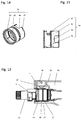
Fig. 18 weiter hervorgeht, ist der Heißwasser-Ringkanal 27 radial innen durch das Mischventil 3 und radial außen durch eine gehäuseseitige Ringkanalwand 31 definiert. Zur Bereitstellung einer Cooltouch-Funktionalität ist in derFig. 18 die Kanalwand 31 im Querschnitt nicht aus einem Vollmaterial gefertigt, sondern vielmehr als ein Hohlprofil ausgeführt, in dem ein Kaltwasser-Kühlkanal 35 geführt ist. Auf diese Weise wird an einer potentiellen Berührfläche 37 des Armaturengehäuses 1 ein Verbrühschutz für den Nutzer bereitgestellt. - In den
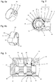
Fig. 1 bis 4 ist ein erstes Ausführungsbeispiel der Erfindung gezeigt, dessen grundsätzlicher Aufbau im Wesentlichen identisch ist mit dem in derFig. 18 erläuterten Aufbau. Von daher wird auf die Beschreibung derFig. 18 verwiesen. Im Unterschied zurFig. 18 ist in denFig. 2 bis 4 der Verbrühschutz nicht mehr mit einer als Hohlprofil ausgeführten Ringkanalwand 31 bereitgestellt, sondern mit einem Isolierelement 39. Das Isolierelement 39 weist gemäß derFig. 3 einen ringfömig geschlossenen Grundkörper 41 auf. In der, in derFig. 3 gezeigten demontierten Fertigungslage weist der ringförmige Grundkörper 41 einen Außendurchmesser auf, der um ein vorgegebenes Übermaß größer ist als der Innendurchmesser der radial äußeren Ringkanalwand 31. Auf diese Weise wird erreicht, dass das Isolierelement 39 in seiner Einbaulage (Fig. 2 oder 4 ) unter Aufbau einer Rückstellkraft in Druckanlage mit der Ringkanalwand 31 verbleibt. - Wie aus der
Fig. 2 weiter hervorgeht, weist das hohlzylindrische Armaturengehäuse 1 an seiner linken Stirnseite 13 eine innere Aufnahmekontur 43 auf, in der das Mischventil 3 eingesetzt ist. Die gehäuseseitige Ringkanalwand 31 ist hierbei ein Bestandteil der inneren Aufnahmekontur 43 des Armaturengehäuses 1. In derFig. 2 ist im Hinblick auf eine einfachere Darstellung lediglich ein Außengehäuse des Thermostat-Mischelementes angedeutet, in dem die Heißwasser-Zuläufe 25 und die Kaltwasser-Zuläufe 26 ausgebildet sind. - Wie aus den
Fig. 2 bis 4 weiter hervorgeht, weist der ringförmige Grundkörper 41 des Isolierelementes 39 eine Heißwasseröffnung 49 auf, die von einem radial nach außen ragenden Einlassstutzen 51 begrenzt ist. Der Einlassstutzen 51 ist gemäß derFig. 2 und 4 formschlüssig in Anlage mit dem Überströmkanal 29, wodurch eine dauerhafte Verdrehsicherung des Isolierelementes 39 gewährleistet ist. - In den
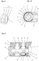
Fig. 5 bis 7 ist ein zweites Ausführungsbeispiel gezeigt, in dem, im Unterschied zum vorangegangenen Ausführungsbeispiel, der ringförmige Grundkörper 41 nicht mehr geschlossen, sondern vielmehr C-förmig offen ausgeführt ist. Auf diese Weise wird eine Montagevereinfachung erzielt. Zudem weist der ringförmige Grundkörper 41 radial nach innen abragende Abstandhalter 53, die sich auf dem Mischventil 3 abstützen und die den ringförmigen Grundkörper 41 mit einer vorgegebenen Vorspannkraft dauerhaft in Druckanlage mit der Heißwasser-Ringkanal 31 bringt. In derFig. 6b ist am Außenumfang des Isolierelements 39 zusätzlich eine Klebschicht 69 aufgebracht. - Im Unterschied zum Stand der Technik ist erfindungsgemäß die Heißwasser-Ringkanalwand 31 im Querschnitt nicht mehr mit einem Hohlprofil (für den Kühlwasserkanal) ausgebildet, sondern vielmehr durchgängig aus einem Vollmaterial sowie mit geringer Wandstärke ausgeführt. Zudem bildet die, von dem Heißwasser-Ringkanal 27 abgewandte Seite der Kanalwand 31 unmittelbar die potentielle Berührfläche 37 für den Nutzer.
- In dem, in den
Fig. 8 bis 10 gezeigten dritten Ausführungsbeispiel ist der Grundkörper 41 des Isolierelementes 39 wiederum ringförmig geschlossen ausgebildet, und zwar mit einer Heißwasser-Öffnung 49, jedoch ohne einen Einlassstutzen 51. Der ringförmige Grundkörper 41 weist gemäß denFig. 8 bis 10 rechtsseitig eine nach innen abgewinkelte Ringschulter 55 auf, an der ein in Axialrichtung nach außen abragender Positionierstift 57 angeordnet ist. Der Positionierstift 57 ragt in derFig. 8 in eine korrespondierende, gehäuseseitige Gegenkontur 59 ein, und zwar unter Bildung einer Verdrehsicherung. - In dem, in den
Fig. 11 und 12 gezeigten vierten Ausführungsbeispiel ist der ringförmige Grundkörper 41 des Isolierelementes in der Axialrichtung unter Bildung eines Mischwasserkanal-Abschnittes 61 bis über das Mischventil 3 hinaus verlängert. Zwischen dem ringförmigen Grundkörper 41 und dem Mischwasserkanal-Abschnitt 61 weist das Isolierelement 39 zusätzlich einen hohlzylindrischen Zentrierabschnitt 63 auf. Dieser ist in der Radialrichtung betrachtet zwischen dem Mischventil 3 und der inneren Aufnahmekontur 43 des Armaturengehäuses 1 angeordnet und unterstützt eine lagerichtige Positionierung des Mischventils 3 im Armaturengehäuse 1. Zudem weist das Isolierelement 39 in denFig. 11 und 12 einen axial abragenden Positionierstift 57 auf, der unter Bildung einer Verdrehsicherung in eine korrespondierende gehäuseseitige Gegenkontur 59 einragt. - In den
Fig. 13 bis 15 ist ein weiteres Ausführungsbeispiel gezeigt, in dem das Isolierelement 39 wiederum einen ringförmig geschlossenen Grundkörper 41 sowie eine Heißwasseröffnung 49 aufweist. Der Grundkörper 41 ist in denFig. 13 bis 15 an seiner, dem Mischkanal 5 axial gegenüberliegenden Seite mit einem hohlzylindrischen Kaltwasser-Abschnitt 65 (Fig. 14 ) verlängert, der eine Kaltwasser-Öffnung 67 aufweist, um durch den das Kaltwasser in die Kaltwasser-Zuläufe 26 des Mischventils 3 einströmen kann. - In den
Fig. 16 und 17 ist in einem fünften Ausführungsbeispiel ein weiteres Isolierelement 39 gezeigt, das einen C-förmigen, das heißt ringförmig offenen Grundkörper 41 aufweist. Radial innenseitig sind am Grundkörper 41 Radialstege angeformt, die sich in der Einbaulage auf dem Mischventil 3 abstützen. Radial außenseitig weist der ringförmige Grundkörper 41 zur Bildung einer Verdrehsicherung eine Rastnase 57 auf, die in Einbaulage (Fig. 16 ) in eine korrespondierende Gegenkontur 59 einragt. -
- 1 Armaturengehäuse
- 3 Mischventil
- 5 Mischwasserkanal
- 7 Wasserverteileinheit
- 9 Verbraucheranschluss
- 11 Oberteil
- 13 Stirnseiten
- 15, 17 Bedienknebel
- 19, 21 Anschlussprofile
- 25, 26 Heiß-/Kaltwasser-Zuläufe
- 27 Heißwasserkanal
- 29 Überströmkanal
- 31 gehäuseseitige Kanalwand
- 35 Kaltwasser-Kanal
- 37 Berührfläche
- 39 Isolierelement
- 41 ringförmiger Grundkörper
- 43 innere Aufnahmekontur
- 49 Heißwasser-Öffnung
- 51 Einlassstutzen
- 53 Abstandhalter
- 55 Ringschulter
- 57 Verdrehsicherungs-Kontur
- 59 Gegenkontur
- 61 Mischwasserkanal
- 63 Zentrierabschnitt
- 65 Kaltwasser-Abschnitt
- 67 Kaltwasser-Öffnung
- 69 Klebschicht
- G Gehäuseachse
Claims (11)
- Sanitärarmatur, mit einem Armaturengehäuse (1), in dem ein nutzerseitig betätigbares Mischventil (3) zur Einstellung einer Mischwassertemperatur angeordnet ist, das über einen Heißwasserkanal (27) mit einem gehäuseseitigen Heißwasseranschluss (19) und über einen Kaltwasserkanal (35) mit einem gehäuseseitigen Kaltwasseranschluss (21) verbunden ist, wobei der Heißwasserkanal (27) zumindest teilweise von einer gehäuseseitigen Kanalwand (31) begrenzt ist, dadurch gekennzeichnet, dass die Sanitärarmatur für einen Verbrühschutz zumindest ein Isolierelement (39) aufweist, das die dem Heißwasserkanal (27) zugewandte Seite der Kanalwand (31) zumindest teilweise überdeckt.
- Sanitärarmatur nach Anspruch 1, dadurch gekennzeichnet, dass die den Heißwasserkanal (27) begrenzende, vom Isolierelement (39) überdeckte Kanalwand (31) im Querschnitt durchgängig aus einem Vollmaterial mit insbesondere geringer Wandstärke gebildet ist, und/oder dass die von dem Heißwasserkanal (27) abgewandte Seite der Kanalwand (31) eine potentielle Berührfläche (37) für den Nutzer bildet.
- Sanitärarmatur nach Anspruch 1 oder 2, dadurch gekennzeichnet, dass der Heißwasserkanal (27) ein um das Mischventil (3) laufender Ringkanal ist, der radial innen vom Mischventil (3) und radial außen von der vom Isolierelement (39) überdeckten, gehäuseseitigen Ringkanalwand (31) begrenzt ist.
- Sanitärarmatur nach einem der vorhergehenden Ansprüche, dadurch gekennzeichnet, dass das Armaturengehäuse (1) hohlzylindrisch ausgebildet ist und an einer Stirnseite (13) eine innere Aufnahmekontur (43) aufweist, in der das Isolierelement (39) eingesetzt ist, und dass insbesondere das Armaturengehäuse (1) quer zur Gehäuseachse (G) hohlzylindrische Anschlussprofile (19, 21) für den Heiß- und Kaltwasseranschluss aufweisen, und dass insbesondere das Heißwasser-Anschlussprofil (19) radial außerhalb der Mischventil-Aufnahmekontur (43) ausgebildet ist.
- Sanitärarmatur nach Anspruch 4, dadurch gekennzeichnet, dass das Armaturengehäuse (1) einen Überströmkanal (29) aufweist, der den Heißwasser-Ringkanal (27) mit dem Heißwasser-Anschlussprofil (19) verbindet.
- Sanitärarmatur nach einem der vorhergehenden Ansprüche, dadurch gekennzeichnet, dass das Isolierelement (39) ein elastisch nachgiebiges Kunststoffteil Ist, und dass insbesondere das Isolierelement (39) einen ringförmig geschlossenen Grundkörper (41) aufweist, dessen Außendurchmesser in seinem demontierten Fertigungszustand um ein Übermaß größer ist als der Innendurchmesser der Ringkanalwand (31), und dass das Isolierelement (39) in seiner Einbaulage unter Aufbau einer Rückstellkraft in Druckanlage mit der Ringkanalwand (31) ist.
- Sanitärarmatur nach Anspruch 6, dadurch gekennzeichnet, dass der ringförmige Grundkörper (41) des Isolierelements (39) C-förmig offen ist, und dass der ringförmige Grundkörper (41) des Isolierelements (39) zumindest eine radial nach innen abragende Stützkontur (53) aufweist, mit der das Isolierelement (39) gegen die Ringkanalwand (31) in Druckanlage bringbar ist.
- Sanitärarmatur nach Anspruch 6 oder 7, dadurch gekennzeichnet, dass der ringförmige Grundkörper (41) des Isolierelements (39) eine Verdrehsicherungs-Kontur (57) aufweist, und dass insbesondere die Verdrehsicherungs-Kontur (57) radial außen am ringförmigen Grundkörper (41) ausgebildet ist oder in Axialrichtung abragt sowie in Eingriff mit einer gehäuseseitigen Gegenkontur (59) ist.
- Sanitärarmatur nach Anspruch 6, 7 oder 8, dadurch gekennzeichnet, dass der ringförmige Grundkörper (41) des Isolierelements (39) eine Heißwasseröffnung (49) aufweist, durch die das Heißwasser in den Heißwasser-Ringkanal (27) einströmbar ist, und/oder dass am ringförmigen Grundkörper (41) ein radial nach außen abragender Einlaufstutzen (51) ausgebildet ist, der die Heißwasseröffnung (49) begrenzt und als Verdrehsicherungs-Kontur (57) in das Heißwasseranschlussprofil (19) oder in den Überströmkanal (29) einragt.
- Sanitärarmatur nach einem der Ansprüche 6 bis 9, dadurch gekennzeichnet, dass sich am Mischventil (3) ausgangsseitig ein Mischwasserkanal (5) anschließt, der zu einer nutzerseitig betätigbaren Wasserverteileinheit (7) geführt ist, in der die Mischwassermenge zu wenigstens einem Verbraucher einstellbar ist, und dass der ringförmige Grundkörper (41) des Isolierelements (39) in Axialrichtung unter Bildung eines Mischwasserkanal-Abschnitt (61) bis über das Mischventil (3) hinaus verlängert ist.
- Sanitärarmatur nach Anspruch 10, dadurch gekennzeichnet, dass das Isolierelement (39) einen hohlzylindrischen Zentrierabschnitt (63) aufweist, der in Axialrichtung betrachtet zwischen dem ringförmigen Grundkörper (41) und dem Mischwasserkanal-Abschnitt (61) ausgebildet ist und in der Radialrichtung betrachtet zwischen dem Mischventil (3) und der hohlzylindrischen inneren Aufnahmekontur (43) des Armaturengehäuses (1) abgestützt ist.
Applications Claiming Priority (1)
| Application Number | Priority Date | Filing Date | Title |
|---|---|---|---|
| DE102015002569.4A DE102015002569A1 (de) | 2015-03-02 | 2015-03-02 | Sanitärarmatur |
Publications (2)
| Publication Number | Publication Date |
|---|---|
| EP3064657A1 true EP3064657A1 (de) | 2016-09-07 |
| EP3064657B1 EP3064657B1 (de) | 2019-10-02 |
Family
ID=55349628
Family Applications (1)
| Application Number | Title | Priority Date | Filing Date |
|---|---|---|---|
| EP16000324.0A Active EP3064657B1 (de) | 2015-03-02 | 2016-02-10 | Sanitärarmatur |
Country Status (4)
| Country | Link |
|---|---|
| EP (1) | EP3064657B1 (de) |
| CN (1) | CN105937642B (de) |
| DE (1) | DE102015002569A1 (de) |
| RU (1) | RU2701326C2 (de) |
Cited By (2)
| Publication number | Priority date | Publication date | Assignee | Title |
|---|---|---|---|---|
| EP3929364A1 (de) * | 2020-06-26 | 2021-12-29 | Grohe AG | Thermostatmischarmatur und verfahren zur deren herstellung |
| CN117083439A (zh) * | 2021-03-19 | 2023-11-17 | 纽珀有限公司 | 卫生功能单元和相关的结构系列和模块 |
Families Citing this family (2)
| Publication number | Priority date | Publication date | Assignee | Title |
|---|---|---|---|---|
| DE102017100710A1 (de) * | 2017-01-16 | 2018-07-19 | Grohe Ag | Unterputzeinbaukörper für eine Sanitärarmatur mit einem zweiteiligen Gehäuse |
| DE102021106083A1 (de) * | 2021-03-12 | 2022-09-15 | Grohe Ag | Thermostatmischarmatur und Verfahren zur deren Herstellung |
Citations (5)
| Publication number | Priority date | Publication date | Assignee | Title |
|---|---|---|---|---|
| EP0645568A1 (de) * | 1993-04-05 | 1995-03-29 | Toto Ltd. | Mischarmatur |
| DE10044684A1 (de) * | 2000-09-08 | 2002-03-21 | Grohe Armaturen Friedrich | Mischbatterie für Kalt- und Heißwasser |
| DE102005052919A1 (de) * | 2005-11-03 | 2007-05-10 | Grohe Ag | Mischbatterie |
| EP2386927A2 (de) | 2010-05-13 | 2011-11-16 | Roca Sanitario, S. A. | Thermostatische Armatur |
| EP2388676A2 (de) * | 2010-04-23 | 2011-11-23 | Suprema (Zhuhai J/V) Thermostatic Sanitaryware Co., Ltd | Verbrühsichere thermostatische Wasserarmatur |
Family Cites Families (6)
| Publication number | Priority date | Publication date | Assignee | Title |
|---|---|---|---|---|
| SU901429A1 (ru) * | 1980-01-25 | 1982-01-30 | за вители | Безвентильный смеситель |
| JPS59164470A (ja) * | 1983-03-04 | 1984-09-17 | Kitamura Gokin Seisakusho:Kk | サ−モスタツト式の湯水混合栓 |
| FR2933470B1 (fr) * | 2008-07-04 | 2013-05-17 | Delabie | Robinet mitigeur thermostatique |
| CN102221100B (zh) * | 2011-06-07 | 2014-07-30 | 浙江苏泊尔卫浴有限公司 | 一种隔热水龙头 |
| CN203115189U (zh) * | 2013-01-04 | 2013-08-07 | 路达(厦门)工业有限公司 | 一种恒温龙头结构 |
| CN203926919U (zh) * | 2014-04-23 | 2014-11-05 | 珠海市舒丽玛温控卫浴设备有限公司 | 表面防烫恒温龙头 |
-
2015
- 2015-03-02 DE DE102015002569.4A patent/DE102015002569A1/de not_active Withdrawn
-
2016
- 2016-02-10 EP EP16000324.0A patent/EP3064657B1/de active Active
- 2016-03-02 RU RU2016107603A patent/RU2701326C2/ru active
- 2016-03-02 CN CN201610118055.1A patent/CN105937642B/zh active Active
Patent Citations (5)
| Publication number | Priority date | Publication date | Assignee | Title |
|---|---|---|---|---|
| EP0645568A1 (de) * | 1993-04-05 | 1995-03-29 | Toto Ltd. | Mischarmatur |
| DE10044684A1 (de) * | 2000-09-08 | 2002-03-21 | Grohe Armaturen Friedrich | Mischbatterie für Kalt- und Heißwasser |
| DE102005052919A1 (de) * | 2005-11-03 | 2007-05-10 | Grohe Ag | Mischbatterie |
| EP2388676A2 (de) * | 2010-04-23 | 2011-11-23 | Suprema (Zhuhai J/V) Thermostatic Sanitaryware Co., Ltd | Verbrühsichere thermostatische Wasserarmatur |
| EP2386927A2 (de) | 2010-05-13 | 2011-11-16 | Roca Sanitario, S. A. | Thermostatische Armatur |
Cited By (2)
| Publication number | Priority date | Publication date | Assignee | Title |
|---|---|---|---|---|
| EP3929364A1 (de) * | 2020-06-26 | 2021-12-29 | Grohe AG | Thermostatmischarmatur und verfahren zur deren herstellung |
| CN117083439A (zh) * | 2021-03-19 | 2023-11-17 | 纽珀有限公司 | 卫生功能单元和相关的结构系列和模块 |
Also Published As
| Publication number | Publication date |
|---|---|
| EP3064657B1 (de) | 2019-10-02 |
| CN105937642B (zh) | 2020-04-07 |
| RU2016107603A3 (de) | 2019-07-17 |
| RU2701326C2 (ru) | 2019-09-25 |
| RU2016107603A (ru) | 2017-09-07 |
| DE102015002569A1 (de) | 2016-09-08 |
| CN105937642A (zh) | 2016-09-14 |
Similar Documents
| Publication | Publication Date | Title |
|---|---|---|
| EP3064657B1 (de) | Sanitärarmatur | |
| DE202017105094U1 (de) | Sanitäre Thermostatarmatur | |
| WO2023143902A1 (de) | Thermostatmischarmatur und verfahren zur deren herstellung | |
| EP3268547A1 (de) | In einen rohrabschnitt über presspassung einsetzbares bauteil | |
| DE102013205250B9 (de) | Rohranschlussadapter und Sanitärarmatur | |
| EP1881390A2 (de) | Thermostat-Mischventil zum Mischen von Kalt-und Warmwasser | |
| DE202016001631U1 (de) | Durchflussmengenregler-Einheit | |
| EP3924652B1 (de) | Ventil für einen unterputzeinbaukörper einer sanitärarmatur mit einem mengenregulierteil und einem temperaturregulierteil | |
| WO2015117768A1 (de) | Armatur mit einem schwenkauslauf | |
| EP4127332B1 (de) | Sanitärarmatur mit einem nicht-axialen thermostatmischer sowie verfahren zur montage einer sanitärarmatur | |
| WO2015117767A1 (de) | Armatur mit einem schwenkauslauf | |
| EP1600839B1 (de) | Durchflussmengenregler | |
| EP2206939B1 (de) | Armatur | |
| DE202004008281U1 (de) | Durchflussmengenregler | |
| EP1692349A1 (de) | Einbauvorrichtung für sanit rarmaturen | |
| EP3931474B1 (de) | Armatur mit ausziehbarem schlauch | |
| DE102005052919B4 (de) | Mischbatterie | |
| DE102011123099B4 (de) | Durchflussmengenregler-Einheit | |
| DE102017123430A1 (de) | Wegeventil | |
| EP3124709B1 (de) | Rosettenvorrichtung | |
| EP4303371B1 (de) | Sanitärarmatur mit verriegelungselement | |
| EP1435480A2 (de) | Sanitärarmatur | |
| DE202012100198U1 (de) | Befestigungsanordnung für sanitäre Bauteile | |
| DE2614790A1 (de) | Badezimmermischbatterie mit thermostatischer temperaturregelung | |
| EP2455642B1 (de) | Sanitäre Einhebel-Mischarmatur |
Legal Events
| Date | Code | Title | Description |
|---|---|---|---|
| PUAI | Public reference made under article 153(3) epc to a published international application that has entered the european phase |
Free format text: ORIGINAL CODE: 0009012 |
|
| AK | Designated contracting states |
Kind code of ref document: A1 Designated state(s): AL AT BE BG CH CY CZ DE DK EE ES FI FR GB GR HR HU IE IS IT LI LT LU LV MC MK MT NL NO PL PT RO RS SE SI SK SM TR |
|
| AX | Request for extension of the european patent |
Extension state: BA ME |
|
| STAA | Information on the status of an ep patent application or granted ep patent |
Free format text: STATUS: REQUEST FOR EXAMINATION WAS MADE |
|
| 17P | Request for examination filed |
Effective date: 20170306 |
|
| RBV | Designated contracting states (corrected) |
Designated state(s): AL AT BE BG CH CY CZ DE DK EE ES FI FR GB GR HR HU IE IS IT LI LT LU LV MC MK MT NL NO PL PT RO RS SE SI SK SM TR |
|
| RIC1 | Information provided on ipc code assigned before grant |
Ipc: E03C 1/04 20060101AFI20190321BHEP Ipc: F16K 11/00 20060101ALI20190321BHEP |
|
| GRAP | Despatch of communication of intention to grant a patent |
Free format text: ORIGINAL CODE: EPIDOSNIGR1 |
|
| STAA | Information on the status of an ep patent application or granted ep patent |
Free format text: STATUS: GRANT OF PATENT IS INTENDED |
|
| INTG | Intention to grant announced |
Effective date: 20190426 |
|
| GRAS | Grant fee paid |
Free format text: ORIGINAL CODE: EPIDOSNIGR3 |
|
| GRAA | (expected) grant |
Free format text: ORIGINAL CODE: 0009210 |
|
| STAA | Information on the status of an ep patent application or granted ep patent |
Free format text: STATUS: THE PATENT HAS BEEN GRANTED |
|
| AK | Designated contracting states |
Kind code of ref document: B1 Designated state(s): AL AT BE BG CH CY CZ DE DK EE ES FI FR GB GR HR HU IE IS IT LI LT LU LV MC MK MT NL NO PL PT RO RS SE SI SK SM TR |
|
| REG | Reference to a national code |
Ref country code: GB Ref legal event code: FG4D Free format text: NOT ENGLISH |
|
| REG | Reference to a national code |
Ref country code: CH Ref legal event code: EP Ref country code: AT Ref legal event code: REF Ref document number: 1186307 Country of ref document: AT Kind code of ref document: T Effective date: 20191015 |
|
| REG | Reference to a national code |
Ref country code: DE Ref legal event code: R096 Ref document number: 502016006846 Country of ref document: DE |
|
| REG | Reference to a national code |
Ref country code: IE Ref legal event code: FG4D Free format text: LANGUAGE OF EP DOCUMENT: GERMAN |
|
| REG | Reference to a national code |
Ref country code: NL Ref legal event code: FP |
|
| REG | Reference to a national code |
Ref country code: LT Ref legal event code: MG4D |
|
| PG25 | Lapsed in a contracting state [announced via postgrant information from national office to epo] |
Ref country code: ES Free format text: LAPSE BECAUSE OF FAILURE TO SUBMIT A TRANSLATION OF THE DESCRIPTION OR TO PAY THE FEE WITHIN THE PRESCRIBED TIME-LIMIT Effective date: 20191002 Ref country code: PL Free format text: LAPSE BECAUSE OF FAILURE TO SUBMIT A TRANSLATION OF THE DESCRIPTION OR TO PAY THE FEE WITHIN THE PRESCRIBED TIME-LIMIT Effective date: 20191002 Ref country code: NO Free format text: LAPSE BECAUSE OF FAILURE TO SUBMIT A TRANSLATION OF THE DESCRIPTION OR TO PAY THE FEE WITHIN THE PRESCRIBED TIME-LIMIT Effective date: 20200102 Ref country code: SE Free format text: LAPSE BECAUSE OF FAILURE TO SUBMIT A TRANSLATION OF THE DESCRIPTION OR TO PAY THE FEE WITHIN THE PRESCRIBED TIME-LIMIT Effective date: 20191002 Ref country code: LV Free format text: LAPSE BECAUSE OF FAILURE TO SUBMIT A TRANSLATION OF THE DESCRIPTION OR TO PAY THE FEE WITHIN THE PRESCRIBED TIME-LIMIT Effective date: 20191002 Ref country code: PT Free format text: LAPSE BECAUSE OF FAILURE TO SUBMIT A TRANSLATION OF THE DESCRIPTION OR TO PAY THE FEE WITHIN THE PRESCRIBED TIME-LIMIT Effective date: 20200203 Ref country code: FI Free format text: LAPSE BECAUSE OF FAILURE TO SUBMIT A TRANSLATION OF THE DESCRIPTION OR TO PAY THE FEE WITHIN THE PRESCRIBED TIME-LIMIT Effective date: 20191002 Ref country code: BG Free format text: LAPSE BECAUSE OF FAILURE TO SUBMIT A TRANSLATION OF THE DESCRIPTION OR TO PAY THE FEE WITHIN THE PRESCRIBED TIME-LIMIT Effective date: 20200102 Ref country code: GR Free format text: LAPSE BECAUSE OF FAILURE TO SUBMIT A TRANSLATION OF THE DESCRIPTION OR TO PAY THE FEE WITHIN THE PRESCRIBED TIME-LIMIT Effective date: 20200103 Ref country code: LT Free format text: LAPSE BECAUSE OF FAILURE TO SUBMIT A TRANSLATION OF THE DESCRIPTION OR TO PAY THE FEE WITHIN THE PRESCRIBED TIME-LIMIT Effective date: 20191002 |
|
| PG25 | Lapsed in a contracting state [announced via postgrant information from national office to epo] |
Ref country code: RS Free format text: LAPSE BECAUSE OF FAILURE TO SUBMIT A TRANSLATION OF THE DESCRIPTION OR TO PAY THE FEE WITHIN THE PRESCRIBED TIME-LIMIT Effective date: 20191002 Ref country code: HR Free format text: LAPSE BECAUSE OF FAILURE TO SUBMIT A TRANSLATION OF THE DESCRIPTION OR TO PAY THE FEE WITHIN THE PRESCRIBED TIME-LIMIT Effective date: 20191002 Ref country code: IS Free format text: LAPSE BECAUSE OF FAILURE TO SUBMIT A TRANSLATION OF THE DESCRIPTION OR TO PAY THE FEE WITHIN THE PRESCRIBED TIME-LIMIT Effective date: 20200224 Ref country code: CZ Free format text: LAPSE BECAUSE OF FAILURE TO SUBMIT A TRANSLATION OF THE DESCRIPTION OR TO PAY THE FEE WITHIN THE PRESCRIBED TIME-LIMIT Effective date: 20191002 |
|
| PG25 | Lapsed in a contracting state [announced via postgrant information from national office to epo] |
Ref country code: AL Free format text: LAPSE BECAUSE OF FAILURE TO SUBMIT A TRANSLATION OF THE DESCRIPTION OR TO PAY THE FEE WITHIN THE PRESCRIBED TIME-LIMIT Effective date: 20191002 |
|
| REG | Reference to a national code |
Ref country code: DE Ref legal event code: R097 Ref document number: 502016006846 Country of ref document: DE |
|
| PG2D | Information on lapse in contracting state deleted |
Ref country code: IS |
|
| PG25 | Lapsed in a contracting state [announced via postgrant information from national office to epo] |
Ref country code: RO Free format text: LAPSE BECAUSE OF FAILURE TO SUBMIT A TRANSLATION OF THE DESCRIPTION OR TO PAY THE FEE WITHIN THE PRESCRIBED TIME-LIMIT Effective date: 20191002 Ref country code: EE Free format text: LAPSE BECAUSE OF FAILURE TO SUBMIT A TRANSLATION OF THE DESCRIPTION OR TO PAY THE FEE WITHIN THE PRESCRIBED TIME-LIMIT Effective date: 20191002 Ref country code: DK Free format text: LAPSE BECAUSE OF FAILURE TO SUBMIT A TRANSLATION OF THE DESCRIPTION OR TO PAY THE FEE WITHIN THE PRESCRIBED TIME-LIMIT Effective date: 20191002 Ref country code: IS Free format text: LAPSE BECAUSE OF FAILURE TO SUBMIT A TRANSLATION OF THE DESCRIPTION OR TO PAY THE FEE WITHIN THE PRESCRIBED TIME-LIMIT Effective date: 20200202 |
|
| PLBE | No opposition filed within time limit |
Free format text: ORIGINAL CODE: 0009261 |
|
| STAA | Information on the status of an ep patent application or granted ep patent |
Free format text: STATUS: NO OPPOSITION FILED WITHIN TIME LIMIT |
|
| PG25 | Lapsed in a contracting state [announced via postgrant information from national office to epo] |
Ref country code: SK Free format text: LAPSE BECAUSE OF FAILURE TO SUBMIT A TRANSLATION OF THE DESCRIPTION OR TO PAY THE FEE WITHIN THE PRESCRIBED TIME-LIMIT Effective date: 20191002 Ref country code: IT Free format text: LAPSE BECAUSE OF FAILURE TO SUBMIT A TRANSLATION OF THE DESCRIPTION OR TO PAY THE FEE WITHIN THE PRESCRIBED TIME-LIMIT Effective date: 20191002 Ref country code: SM Free format text: LAPSE BECAUSE OF FAILURE TO SUBMIT A TRANSLATION OF THE DESCRIPTION OR TO PAY THE FEE WITHIN THE PRESCRIBED TIME-LIMIT Effective date: 20191002 |
|
| 26N | No opposition filed |
Effective date: 20200703 |
|
| REG | Reference to a national code |
Ref country code: CH Ref legal event code: PL |
|
| GBPC | Gb: european patent ceased through non-payment of renewal fee |
Effective date: 20200210 |
|
| REG | Reference to a national code |
Ref country code: BE Ref legal event code: MM Effective date: 20200229 |
|
| PG25 | Lapsed in a contracting state [announced via postgrant information from national office to epo] |
Ref country code: MC Free format text: LAPSE BECAUSE OF FAILURE TO SUBMIT A TRANSLATION OF THE DESCRIPTION OR TO PAY THE FEE WITHIN THE PRESCRIBED TIME-LIMIT Effective date: 20191002 Ref country code: LU Free format text: LAPSE BECAUSE OF NON-PAYMENT OF DUE FEES Effective date: 20200210 |
|
| PG25 | Lapsed in a contracting state [announced via postgrant information from national office to epo] |
Ref country code: LI Free format text: LAPSE BECAUSE OF NON-PAYMENT OF DUE FEES Effective date: 20200229 Ref country code: CH Free format text: LAPSE BECAUSE OF NON-PAYMENT OF DUE FEES Effective date: 20200229 Ref country code: SI Free format text: LAPSE BECAUSE OF FAILURE TO SUBMIT A TRANSLATION OF THE DESCRIPTION OR TO PAY THE FEE WITHIN THE PRESCRIBED TIME-LIMIT Effective date: 20191002 |
|
| PG25 | Lapsed in a contracting state [announced via postgrant information from national office to epo] |
Ref country code: IE Free format text: LAPSE BECAUSE OF NON-PAYMENT OF DUE FEES Effective date: 20200210 Ref country code: GB Free format text: LAPSE BECAUSE OF NON-PAYMENT OF DUE FEES Effective date: 20200210 |
|
| PG25 | Lapsed in a contracting state [announced via postgrant information from national office to epo] |
Ref country code: BE Free format text: LAPSE BECAUSE OF NON-PAYMENT OF DUE FEES Effective date: 20200229 |
|
| REG | Reference to a national code |
Ref country code: AT Ref legal event code: MM01 Ref document number: 1186307 Country of ref document: AT Kind code of ref document: T Effective date: 20210210 |
|
| PG25 | Lapsed in a contracting state [announced via postgrant information from national office to epo] |
Ref country code: AT Free format text: LAPSE BECAUSE OF NON-PAYMENT OF DUE FEES Effective date: 20210210 |
|
| PG25 | Lapsed in a contracting state [announced via postgrant information from national office to epo] |
Ref country code: TR Free format text: LAPSE BECAUSE OF FAILURE TO SUBMIT A TRANSLATION OF THE DESCRIPTION OR TO PAY THE FEE WITHIN THE PRESCRIBED TIME-LIMIT Effective date: 20191002 Ref country code: MT Free format text: LAPSE BECAUSE OF FAILURE TO SUBMIT A TRANSLATION OF THE DESCRIPTION OR TO PAY THE FEE WITHIN THE PRESCRIBED TIME-LIMIT Effective date: 20191002 Ref country code: CY Free format text: LAPSE BECAUSE OF FAILURE TO SUBMIT A TRANSLATION OF THE DESCRIPTION OR TO PAY THE FEE WITHIN THE PRESCRIBED TIME-LIMIT Effective date: 20191002 |
|
| PG25 | Lapsed in a contracting state [announced via postgrant information from national office to epo] |
Ref country code: MK Free format text: LAPSE BECAUSE OF FAILURE TO SUBMIT A TRANSLATION OF THE DESCRIPTION OR TO PAY THE FEE WITHIN THE PRESCRIBED TIME-LIMIT Effective date: 20191002 |
|
| P01 | Opt-out of the competence of the unified patent court (upc) registered |
Effective date: 20230526 |
|
| PGFP | Annual fee paid to national office [announced via postgrant information from national office to epo] |
Ref country code: NL Payment date: 20260206 Year of fee payment: 11 |
|
| PGFP | Annual fee paid to national office [announced via postgrant information from national office to epo] |
Ref country code: DE Payment date: 20260202 Year of fee payment: 11 |
|
| PGFP | Annual fee paid to national office [announced via postgrant information from national office to epo] |
Ref country code: FR Payment date: 20260206 Year of fee payment: 11 |