EP3064358A1 - Recording apparatus - Google Patents
Recording apparatus Download PDFInfo
- Publication number
- EP3064358A1 EP3064358A1 EP16153211.4A EP16153211A EP3064358A1 EP 3064358 A1 EP3064358 A1 EP 3064358A1 EP 16153211 A EP16153211 A EP 16153211A EP 3064358 A1 EP3064358 A1 EP 3064358A1
- Authority
- EP
- European Patent Office
- Prior art keywords
- nozzle
- recording
- cover portion
- recording head
- recording apparatus
- Prior art date
- Legal status (The legal status is an assumption and is not a legal conclusion. Google has not performed a legal analysis and makes no representation as to the accuracy of the status listed.)
- Withdrawn
Links
- 239000007788 liquid Substances 0.000 claims abstract description 43
- 230000032258 transport Effects 0.000 claims description 37
- 239000000463 material Substances 0.000 claims description 8
- 239000003595 mist Substances 0.000 description 30
- 238000010276 construction Methods 0.000 description 23
- 239000000976 ink Substances 0.000 description 19
- 230000007723 transport mechanism Effects 0.000 description 15
- 238000004140 cleaning Methods 0.000 description 12
- 230000007246 mechanism Effects 0.000 description 8
- 238000004804 winding Methods 0.000 description 7
- 230000007423 decrease Effects 0.000 description 6
- 238000010586 diagram Methods 0.000 description 4
- 230000002401 inhibitory effect Effects 0.000 description 4
- 230000002452 interceptive effect Effects 0.000 description 4
- 238000005406 washing Methods 0.000 description 4
- 230000008901 benefit Effects 0.000 description 3
- 230000015556 catabolic process Effects 0.000 description 3
- 238000006731 degradation reaction Methods 0.000 description 3
- 230000002829 reductive effect Effects 0.000 description 3
- 238000012986 modification Methods 0.000 description 2
- 230000004048 modification Effects 0.000 description 2
- 238000004381 surface treatment Methods 0.000 description 2
- 238000010521 absorption reaction Methods 0.000 description 1
- 239000003795 chemical substances by application Substances 0.000 description 1
- 238000000151 deposition Methods 0.000 description 1
- 239000003599 detergent Substances 0.000 description 1
- 238000007599 discharging Methods 0.000 description 1
- 239000004744 fabric Substances 0.000 description 1
- 238000012423 maintenance Methods 0.000 description 1
- 238000004519 manufacturing process Methods 0.000 description 1
- 230000036961 partial effect Effects 0.000 description 1
- 230000009467 reduction Effects 0.000 description 1
- 239000005871 repellent Substances 0.000 description 1
- 238000001179 sorption measurement Methods 0.000 description 1
Images



Classifications
-
- B—PERFORMING OPERATIONS; TRANSPORTING
- B41—PRINTING; LINING MACHINES; TYPEWRITERS; STAMPS
- B41J—TYPEWRITERS; SELECTIVE PRINTING MECHANISMS, i.e. MECHANISMS PRINTING OTHERWISE THAN FROM A FORME; CORRECTION OF TYPOGRAPHICAL ERRORS
- B41J2/00—Typewriters or selective printing mechanisms characterised by the printing or marking process for which they are designed
- B41J2/005—Typewriters or selective printing mechanisms characterised by the printing or marking process for which they are designed characterised by bringing liquid or particles selectively into contact with a printing material
- B41J2/01—Ink jet
- B41J2/135—Nozzles
- B41J2/165—Prevention or detection of nozzle clogging, e.g. cleaning, capping or moistening for nozzles
- B41J2/16505—Caps, spittoons or covers for cleaning or preventing drying out
-
- B—PERFORMING OPERATIONS; TRANSPORTING
- B41—PRINTING; LINING MACHINES; TYPEWRITERS; STAMPS
- B41J—TYPEWRITERS; SELECTIVE PRINTING MECHANISMS, i.e. MECHANISMS PRINTING OTHERWISE THAN FROM A FORME; CORRECTION OF TYPOGRAPHICAL ERRORS
- B41J2/00—Typewriters or selective printing mechanisms characterised by the printing or marking process for which they are designed
- B41J2/005—Typewriters or selective printing mechanisms characterised by the printing or marking process for which they are designed characterised by bringing liquid or particles selectively into contact with a printing material
- B41J2/01—Ink jet
- B41J2/135—Nozzles
- B41J2/165—Prevention or detection of nozzle clogging, e.g. cleaning, capping or moistening for nozzles
- B41J2/16517—Cleaning of print head nozzles
-
- B—PERFORMING OPERATIONS; TRANSPORTING
- B41—PRINTING; LINING MACHINES; TYPEWRITERS; STAMPS
- B41J—TYPEWRITERS; SELECTIVE PRINTING MECHANISMS, i.e. MECHANISMS PRINTING OTHERWISE THAN FROM A FORME; CORRECTION OF TYPOGRAPHICAL ERRORS
- B41J2/00—Typewriters or selective printing mechanisms characterised by the printing or marking process for which they are designed
- B41J2/005—Typewriters or selective printing mechanisms characterised by the printing or marking process for which they are designed characterised by bringing liquid or particles selectively into contact with a printing material
- B41J2/01—Ink jet
- B41J2/135—Nozzles
- B41J2/165—Prevention or detection of nozzle clogging, e.g. cleaning, capping or moistening for nozzles
- B41J2/16517—Cleaning of print head nozzles
- B41J2/16535—Cleaning of print head nozzles using wiping constructions
-
- B—PERFORMING OPERATIONS; TRANSPORTING
- B41—PRINTING; LINING MACHINES; TYPEWRITERS; STAMPS
- B41J—TYPEWRITERS; SELECTIVE PRINTING MECHANISMS, i.e. MECHANISMS PRINTING OTHERWISE THAN FROM A FORME; CORRECTION OF TYPOGRAPHICAL ERRORS
- B41J2/00—Typewriters or selective printing mechanisms characterised by the printing or marking process for which they are designed
- B41J2/005—Typewriters or selective printing mechanisms characterised by the printing or marking process for which they are designed characterised by bringing liquid or particles selectively into contact with a printing material
- B41J2/01—Ink jet
- B41J2/135—Nozzles
- B41J2/165—Prevention or detection of nozzle clogging, e.g. cleaning, capping or moistening for nozzles
- B41J2/16517—Cleaning of print head nozzles
- B41J2/16535—Cleaning of print head nozzles using wiping constructions
- B41J2/16538—Cleaning of print head nozzles using wiping constructions with brushes or wiper blades perpendicular to the nozzle plate
-
- B—PERFORMING OPERATIONS; TRANSPORTING
- B41—PRINTING; LINING MACHINES; TYPEWRITERS; STAMPS
- B41J—TYPEWRITERS; SELECTIVE PRINTING MECHANISMS, i.e. MECHANISMS PRINTING OTHERWISE THAN FROM A FORME; CORRECTION OF TYPOGRAPHICAL ERRORS
- B41J2/00—Typewriters or selective printing mechanisms characterised by the printing or marking process for which they are designed
- B41J2/005—Typewriters or selective printing mechanisms characterised by the printing or marking process for which they are designed characterised by bringing liquid or particles selectively into contact with a printing material
- B41J2/01—Ink jet
- B41J2/135—Nozzles
- B41J2/165—Prevention or detection of nozzle clogging, e.g. cleaning, capping or moistening for nozzles
- B41J2/16517—Cleaning of print head nozzles
- B41J2/16535—Cleaning of print head nozzles using wiping constructions
- B41J2/16544—Constructions for the positioning of wipers
Definitions
- the present invention relates to a recording apparatus.
- Recording apparatuses that have a recording head that performs recording by ejecting a liquid such as ink from nozzles onto a recording medium while moving the recording head back and forth relative to the recording medium have been used.
- recording quality sometimes declines due to mist produced as the recording head ejects the liquid. Therefore, many recording apparatuses in use are equipped with a wiper that wipes such mist.
- JP-A-6-115065 and JP-A-2014-46502 disclose recording apparatuses each equipped with a wiper capable of wiping a nozzle-formed surface in which nozzles are formed.
- the recording speed needs to be reduced in order to inhibit decline in recording quality due to mist produced as the recording head ejects liquid.
- An advantage of some aspects of the invention is that it becomes possible to inhibit the recording quality from declining due to mist produced as the recording head ejects liquid, without reducing the recording speed.
- a recording apparatus includes a recording head capable of moving back and forth relative to a recording medium and ejecting a liquid from a nozzle, a cover portion that covers at least a portion of a no-nozzle-formed region in which the nozzle is not formed within a nozzle-formed surface in which the nozzle is formed, and a wiper provided in a back-and-forth movement range of the recording head and capable of wiping the cover portion without contacting the nozzle-formed surface as the recording head moves back and forth.
- the cover portion may have higher liquid repellency to the liquid than the wiper does.
- the liquid repellency of the cover portion to the liquid may be higher in a region near the nozzle than in a region remote from the nozzle.
- the wiper may be a blade that extends in a direction that intersects reciprocating directions of the recording head.
- a plurality of the nozzle may be arranged in a direction that intersects reciprocating directions of the recording head.
- the wiper may be capable of wiping in a direction that intersects the reciprocating directions of the recording head.
- the wiper may be made of a material capable of absorbing the liquid.
- the wiper may be capable of being withdrawn from a location at which the wiper is able to wipe the cover portion as the recording head moves back and forth.
- ratio of a thickness of a cover region in the cover portion which covers the nozzle-formed surface to a length of an exposed region in the nozzle-formed surface which is not covered with the cover portion, the length being measured in reciprocating directions of the recording head may be greater than or equal to 0.02 and less than or equal to 3.0.
- the ratio of the thickness of the cover region to the length of the exposed region may be greater than or equal to 0.5 and less than or equal to 2.4.
- the foregoing recording apparatus may further include a transport portion that transports the recording medium in a direction that intersects reciprocating directions of the recording head, and the wiper may be provided at an end portion of a transport region in which the recording medium is transported by the transport portion, the end portion being at an end in one of the reciprocating directions.
- the wiper may be provided at each of two end portions of the transport region in the reciprocating directions.
- Fig. 1 is a schematic side view of the recording apparatus 1 of this exemplary embodiment.
- Fig. 2 and Fig. 3 are schematic diagrams of portions in and around a transport mechanism 3 that transports a recording medium P and that is equipped with wipers 19 that are portions of the recording apparatus 1 of this exemplary embodiment.
- Fig. 2 is a schematic front view and Fig. 3 is a schematic plan view.
- the recording apparatus 1 of this exemplary embodiment includes a feeder portion 2 capable of feeding the recording medium P on which to perform recording by unwinding a roll R1 of the recording medium P.
- the recording apparatus 1 further includes a transport mechanism 3 as a transport portion that transports the recording medium P in a transporting direction A by a tacky belt 10 that supports the recording medium P on a support surface F that has a tackiness agent thereon.
- a recorder mechanism 4 that performs recording on the recording medium P by moving a recording head 7 back and forth in reciprocating directions B that intersect the recording medium P-transporting direction A.
- a washer mechanism 15 for the tacky belt 10 is also provided.
- a winder mechanism 18 having a winding shaft 17 that winds up the recording medium P and a cutter 16 that cuts the recording medium P wound around the winding shaft 17 is provided.
- the feeder portion 2 includes a rotation shaft 5 on which the roll R1 of the recording medium P for recording is set, and is capable of feeding the recording medium P from the roll R1 set on the rotation shaft 5 to the transport mechanism 3 via a driven roller 6.
- the rotation shaft 5 rotates in a rotation direction C.
- the transport mechanism 3 includes the tacky belt 10 that supports and transports thereon the recording medium P fed from the feeder portion 2, a transport roller 8 provided as a driving roller that moves the tacky belt 10, and a driven roller 9.
- the recording medium P is mounted on and stuck to a support surface F of the tacky belt 10 by a pressure roller 12 pressurizing the recording medium P onto the support surface F.
- the transport roller 8 rotates in the rotation direction C so that the tacky belt 10 moves in a direction E.
- the transport belt is not limited to a tacky belt.
- an electrostatic adsorption type transport belt may be used.
- the recorder mechanism 4 includes the recording head 7 capable of ejecting ink (liquid) from nozzles N (see Figs. 5A and 5B and Fig. 6 ) and a carriage motor 30 (see Fig. 4 ) that moves a carriage on which the recording head 7 is mounted back and forth in the reciprocating directions B relative to the recording medium P.
- the reciprocating directions B are directions perpendicular to the sheet of the drawing.
- the recording head 7 is moved back and forth for recording.
- the transport mechanism 3 avoids transporting the recording medium P.
- the back and forth movements of the recording head 7 and the transport of the recording medium P are alternately performed.
- the transport mechanism 3 intermittently transports the recording medium P (intermittently moves the tacky belt 10) corresponding to the back and forth movements of the recording head 7.
- the wipers 19 are provided at two opposite end portions 35 of a recording region Rp of the recording head 7 in the reciprocating directions B.
- the recording region Rp is in a transport region Rc in which the recording medium P is transported by the transport mechanism 3.
- the recording apparatus 1 of this exemplary embodiment is configured to be capable of wiping the recording head 7 by using the wipers 19 during recording.
- the wipers 19 are movable in directions D and can be withdrawn so as to avoid contact with the recording head 7 during recording.
- the recording apparatus 1 of this exemplary embodiment has a maintenance portion that includes a cap, wipers, a suction mechanism, etc., and that is capable of maintaining the recording head 7 when the recording head 7 is positioned at a home position.
- the washer mechanism 15 for the tacky belt 10 includes a washing brush 13 in which a plurality of washing rollers are connected in a rotation axis direction and a tray 14 that holds therein a detergent for washing the washing brush 13.
- the winder mechanism 18 winds up the recording medium P that has been subjected to recording and transported from the transport mechanism 3 via a driven roller 11.
- a medium-winding paper tube or the like is set on the winding shaft 17, and the recording medium P is wound up as a roll R2 on the paper tube or the like.
- the recording apparatus 1 of this exemplary embodiment is a recording apparatus in which a roll of the recording medium P is set and the recording medium P from the roll is supported and transported on the tacky belt 10, this construction is not restrictive.
- the recording apparatus of the invention may have a construction in which instead of a rolled recording medium P, a cut sheet-shaped recording medium P can be transported by a pair of rollers that constitute a transport portion and that clamp the recording medium P.
- Fig. 4 is a block diagram of the recording apparatus 1 of this exemplary embodiment.
- a control unit 23 includes a CPU (central processing unit) 24 that performs overall control of the recording apparatus 1.
- the CPU 24 is connected via a system bus 25 to a ROM (read-only memory) 26 that stores various control programs that the CPU 24 executes and the like and a RAM (random access memory) 27 capable of temporarily storing data.
- ROM read-only memory
- RAM random access memory
- the CPU 24 is also connected via the system bus 25 to a head driving portion 28 that drives the recording head 7.
- the CPU 24 is connected via the system bus 25 to a motor driving portion 29 that drives a carriage motor 30, a transporting motor 31, a feeding motor 32, a winding motor 33, and a wiper moving motor 34.
- the carriage motor 30 is a motor that moves the carriage on which the recording head 7 is mounted.
- the transporting motor 31 is a motor that drives the transport roller 8.
- the feeding motor 32 is a motor that is a rotation mechanism for the rotation shaft 5 and that drives the rotation shaft 5 in order to feed the recording medium P to the transport mechanism 3.
- the winding motor 33 is a driving motor that rotates the winding shaft 17.
- the wiper moving motor 34 is a motor that moves the wipers 19 in the directions D.
- the CPU 24 is also connected via the system bus 25 to a cutter driving portion 36 that drives the cutter 16 so that the cutter 16 cuts the recording medium P.
- the CPU 24 is connected via the system bus 25 to an input/output portion 37.
- the input/output portion 37 is connected to a PC (personal computer) 38 that inputs recording data or the like from an external device or the like.
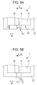
- Figs. 5A and 5B are schematic front views presenting the recording head 7 of this exemplary embodiment.
- Fig. 5A presents a state in which the recording head 7 is not in contact with either one of the wipers 19.
- Fig. 5B presents a state in which the recording head 7 is in contact with one of the wipers 19 when moving in a direction B1 that is one of the reciprocating directions B.
- Fig. 6 is a schematic bottom view presenting the recording head 7 of this exemplary embodiment.
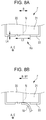
- Figs. 8A and 8B are schematic front views presenting a related-art recording head 7 and correspond to Figs. 5A and 5B .
- Fig. 8A presents a state in which the recording head 7 is not in contact with either one of the wipers 19, and Fig. 8B presents a state in which the recording head 7 is in contact with one of the wipers 19.
- the recording head 7 in the present exemplary embodiment of the invention includes a nozzle plate 21 in which the nozzles N are formed and a cover portion 22 that covers at least a portion of a non-nozzle-N-formed region Rn in the nozzle-formed surface 20 of the nozzle plate 21.
- the recording head 7 of this exemplary embodiment includes the nozzle plate 21 in which the nozzles N are formed and the cover portion 22 that covers at least a portion of the nozzle-formed surface 20 of the nozzle plate 21 without contacting a nozzle N.
- Each of the wipers 19 is provided in a back-and-forth movement range Rh and, as presented in in Fig. 5B , is capable of wiping the cover portion 22 without contacting the nozzle-formed surface 20 as the recording head 7 moves back and forth.
- the wipers 19 are able to wipe the cover portion 22 without contacting the nozzle-formed surface 20 because a thickness L2 of a cover region in the cover portion 22 which actually covers the nozzle-formed surface 20 is sufficiently large relative to a length L1 of an exposed region Ro in the nozzle-formed surface 20 which is not covered with the cover portion 22, the length L1 being measured in the reciprocating directions B of the recording head 7.
- the cover portion 22 that covers at least a portion of the non-nozzle-N-formed region Rn in the nozzle-formed surface 20 is provided as in the recording apparatus 1 of this exemplary embodiment, the area of the exposed region Ro becomes small, so that deposit of mist on the nozzle-formed surface 20 can be inhibited or reduced. Furthermore, since the wipers 19 are provided in the back-and-forth movement range Rh of the recording head 7, the mist deposited on the cover portion 22 instead of the nozzle-formed surface 20 can be wiped by the wipers 19 provided in the back-and-forth movement range Rh of the recording head 7 even during recording, without the wipers 19 contacting the nozzle-formed surface 20.
- the recording apparatus 1 of this exemplary embodiment is capable of cleaning the cover portion 22, without reducing the recording speed, while inhibiting the mist or the like deposited on the nozzle-formed surface 20 from being pushed into the nozzles N. Therefore, the recording apparatus 1 is capable of inhibiting the decline in recording quality due to mist produced as the recording head 7 ejects ink, without reducing the recording speed.
- the thickness L4 of the cover region is small in relation to the length L3 of the exposed region Ro, so that the wipers 19 cannot wipe the cover portion 22 without contacting the nozzle-formed surface 20. Therefore, if wiping is performed during recording, there is a risk that mist or the like deposited on the cover portion 22 or the nozzle-formed surface 20 may be pushed into the nozzles N and therefore the recording quality may decline.
- the ratio of the thickness L2 of the cover region to the length L1 of the exposed region Ro is desired to be greater than or equal to 0.02 and less than or equal to 3.0.
- the ratio is desired to be greater than or equal to 0.02 and less than or equal to 3.0.
- contact of the wipers 19 with the nozzle-formed surface 20 can be effectively inhibited.
- the distance from the nozzle-formed surface 20 to the recording medium P is set to a short distance in order to maintain a recording quality and inhibit production of mist. Despite this setting, the aforementioned setting of the ratio to 3.0 or less will substantially prevent contact of the cover portion 22 with the recording medium P.
- the ratio of the thickness L2 of the cover region to the length L1 of the exposed region Ro is greater than or equal to 0.5 and less than or equal to 2.4, it is possible to switch between the cleaning in which the wipers 19 wipe without contacting the nozzle-formed surface 20 and the cleaning in which the wipers 19 wipe contacting the nozzle-formed surface 20 by, for example, changing the contact pressure of the wipers 19 on the recording head 7. Therefore, the cleaning can be suitably carried out with ease, for example, if ink is firmly adhered to the exposed region Ro and therefore the cleaning in which the wipers 19 wipe contacting the nozzle-formed surface 20 is desirable.
- the recording apparatus 1 of this exemplary embodiment is capable of using black, cyan, magenta, and yellow inks.
- the recording head 7 of the exemplary embodiment as presented in Fig. 6 , four recording heads 7a, 7b, 7c and 7d that correspond to the black, cyan, magenta, and yellow inks, respectively, and that have substantially the same construction are arranged side by side in the reciprocating directions B.
- Figs. 5A and 5B are partial side sectional views that correspond to each one of the recording heads 7a, 7b, 7c and 7d.
- a plurality of rows of nozzles that eject a plurality of inks may be arranged in a single nozzle plate 21.
- the recording apparatus 1 of Exemplary Embodiment 1 further includes the transport mechanism 3 that transports the recording medium P in the transporting direction A that intersects the reciprocating directions B of the recording head 7.
- the wipers 19 are provided at end portions 35 of the transport region Rc where the recording medium P is transported by the transport mechanism 3, the end portions 35 being at ends in the reciprocating directions B. That is, the wipers 19 are provided at locations that are within the back-and-forth movement range Rh of the recording head 7 and outside the recording region Rp, so that the wipers 19 can wipe the cover portion 22 without interfering with the recording operation.
- the wipers 19 in this exemplary embodiment are provided at the two end portions 35 of the transport region Rc where the recording medium P is transported by the transport mechanism 3, the two end portions 35 being at ends in the reciprocating directions B. Therefore, the cover portion 22 can be wiped effectively by the two wipers 19, without interfering with the recording operation.
- the wipers 19 in the exemplary embodiment can be withdrawn from the location at which the wipers 19 are able to wipe the cover portion 22 as the recording head 7 moves back and forth during the recording operation, by the control unit 23 controlling the wiper moving motor 34. That is, when there is no need to wipe the cover portion 22 every time the recording head 7 moves back and forth, it is possible to perform wiping at every predetermined number of back and forth movements of the recording head 7.
- the recording apparatus 1 of this exemplary embodiment is configured to be able to inhibit the degradation of the wipers 19 and the cover portion 22 due to frequent contacts therebetween.
- the cover portion 22 is made of a material that has higher liquid repellency to ink than the wipers 19. That is, the cover portion 22 is less easily wetted by ink than the wipers 19 are. Therefore, as the wipers 19 wipe the cover portion 22, the ink on the cover portion 22 (ink mist deposited on the cover portion 22) efficiently moves to the wipers 19.
- cover portion 22 more liquid ink-repellent than the wipers 19 is not particularly limited.
- Such different liquid repellencies of the cover portion 22 and the wipers 19 to ink may be achieved by, for example, making the cover portion 22 and the wipers 19 from different materials, subjecting the cover portion 22 and the wipers 19 to different surface treatments, etc.
- the cover portion 22 has been formed so that the liquid repellency to ink is higher at locations near the nozzles N than at locations remote from the nozzles N. Therefore, mist deposited on the cover portion 22 moves more easily from the vicinity of the nozzles N (a region near the nozzle-formed surface 20) toward locations remote from the nozzles N (a region near the side surfaces of the cover portion 22), so that mist is effectively inhibited from being pushed into the nozzles N.
- the construction in which the liquid repellency to ink is higher in a region near the nozzles N than in a region remote from the nozzles N includes a construction in which an inner side surface of the cover portion 22 which faces the exposed region Ro and which extends along the direction of the thickness L2 has higher ink repellency than other surfaces of the cover portion 22.
- liquid repellency to ink higher in a region near the nozzles N than in a region remote from the nozzles N is not particularly limited.
- Such different liquid repellencies to ink may be achieved by, for example, using different materials, employing different surface treatments, etc.
- the wipers 19 are blade type wipers that contact the cover portion 22 (a member to be wiped) and scrape mist from the cover portion 22. More specifically, the wipers 19 are blades that extend in directions that intersect the reciprocating directions B of the recording head 7. Therefore, the wipers 19 are simple in construction and low in cost. However, such a construction of wipers is not restrictive.
- the wipers may be liquid absorption type wipers made of a material capable of absorbing a liquid such as ink or the like, for example, a cloth or the like.
- a wiper having such a construction can more effectively inhibit mist being pushed into nozzles by the wiper than the blade type wiper.
- Fig. 7 is a schematic diagram of portions in and around a transport mechanism 3 that transports a recording medium P, with wipers 19 (only one wiper is shown) that are portions of the recording apparatus 1 according to Exemplary Embodiment 2 of the invention, corresponding to Fig. 3 presenting portions in and around the transport mechanism 3 of Exemplary Embodiment 1.
- wipers 19 only one wiper is shown
- Fig. 3 presenting portions in and around the transport mechanism 3 of Exemplary Embodiment 1.
- component members of Exemplary Embodiment 2 comparable to those of Exemplary Embodiment 1 are denoted by the same characters and detailed descriptions thereof are omitted below.
- the recording apparatus 1 of this exemplary embodiment is different from the recording apparatus 1 of Exemplary Embodiment 1 only in the construction of the wipers 19.
- the wipers 19 in Exemplary Embodiment 1 are blade type wipers that extend along the transporting direction A.
- the wipers 19 in Exemplary Embodiment 2, as presented in Fig. 7 are blade type wipers that extend in the reciprocating directions B and that are movable in directions G along the transporting direction A. During a period from when the recording head 7 that moves in the reciprocating directions B in a recording operation moves out of the recording region Rp, decelerates, stops, and then begins to move in the opposite direction to when the recording head 7 re-enters the recording region Rp, the wipers 19 can move in the directions G to wipe the cover portion 22 of the recording head 7.
- the recording apparatus 1 of this exemplary embodiment includes the recording head 7 that has a nozzle-formed surface 20 in which nozzles N are arranged in the directions G that intersect the reciprocating directions B and the wipers 19 capable of wiping in the directions G of arrangement of the nozzles N (i.e., the nozzle row directions).
- a recording apparatus 1 includes a recording head 7 capable of moving back and forth relative to a recording medium P and ejecting a liquid from a nozzle N, a cover portion 22 that covers at least a portion of a no-nozzle-formed region Rn in which the nozzle N is not formed within a nozzle-formed surface 20 in which the nozzle N is formed, and a wiper 19 provided in a back-and-forth movement range Rh of the recording head 7 and capable of wiping the cover portion 22 without contacting the nozzle-formed surface 20 as the recording head 7 moves back and forth.
- nozzle-formed surface 20" in the "non-nozzle-N-formed region Rn" means the entire region in the nozzle-formed surface 20 in which no nozzle N is formed.
- the provision of the cover portion 22 that covers at least a portion of the non-nozzle-N-formed region Rn in the nozzle-formed surface 20 inhibits mist from depositing on the nozzle-formed surface 20. Furthermore, the mist having deposited on the cover portion 22 instead of the nozzle-formed surface 20 can be wiped off even during recording by the wiper 19 provided in the back-and-forth movement range Rh of the recording head 7, without contacting the nozzle-formed surface 20. Therefore, the recording apparatus 1 can clean the cover portion 22 while avoiding reduction in the recording speed and inhibiting mist or the like deposited on the nozzle-formed surface 20 from being pushed into the nozzles N. Hence, the recording apparatus 1 can inhibit the decline in recording quality due to mist produced as the recording head 7 ejects liquid, without reducing the recording speed.
- the cover portion 22 has higher liquid repellency to the liquid than the wiper 19 does.
- the cover portion 22 has higher liquid repellency to the liquid than the wiper 19 does. That is, the cover portion 22 is less easily wetted by the liquid than the wiper 19 is. Therefore, as the wiper 19 wipes the cover portion 22, the liquid on the cover portion 22 (mist deposited on the cover portion 22) will efficiently move to the wiper 19.
- the liquid repellency of the cover portion 22 to the liquid is higher in a region near the nozzle N than in a region remote from the nozzle N.
- the liquid repellency of the cover portion 22 to the liquid is higher in the region near the nozzle N than in the region remote from the nozzle N. Therefore, mist deposited on the cover portion 22 moves more easily from the region near the nozzle N toward the region remote from the nozzle N, so that mist can be effectively inhibited from being pushed into the nozzle N.
- the wiper 19 is a blade that extends in a direction that intersects the reciprocating directions B of the recording head 7.
- the wiper 19 is a blade extending in a direction that intersects the reciprocating directions B of the recording head 7. Therefore, the wiper 19 can be easily constructed at low cost.
- the nozzle N is arranged in a direction G that intersects reciprocating directions B of the recording head 7. Furthermore, the wiper 19 is capable of wiping along the direction G in which the nozzles N are arranged.
- nozzles N are arranged in the nozzle-formed surface 20 in the direction G that intersects the reciprocating directions B of the recording head 7, and wipers 19 can wipe along the direction G in which the nozzles N are arranged. That is, the wiping can be performed along rows of nozzles.
- This construction makes it possible to easily avoid forming a construction in which the cover portion 22 is wiped by the wiper 19 in a direction that intersects the direction of the length of the exposed region Ro in the nozzle-formed surface 20 which is not covered by the cover portion 22 (a construction in which the wiper 19 is likely to contact the nozzle-formed surface 20). Therefore, a construction in which the wiper 19 is unlikely to contact the nozzle-formed surface 20 can be easily provided, so that a construction in which mist is unlikely to be pushed into the nozzle N can be easily provided.
- the wiper 19 is made of a material capable of absorbing the liquid.
- the wiper 19 is made of a material that can absorb the liquid. Therefore, mist can be effectively inhibited from being pushed into the nozzles N by the wiper 19.
- the wiper 19 is capable of being withdrawn from a location at which the wiper 19 is able to wipe the cover portion 22 as the recording head 7 moves back and forth.
- the wiper 19 can be withdrawn from the location at which the wiper 19 can wipe the cover portion 22 as the recording head 7 moves back and forth. Therefore, when there is no need to wipe the cover portion 22 every time the recording head 7 moves back or forth, the recording apparatus 1 can perform wiping at every predetermined number of back and forth movements of the recording head 7. Hence, the degradation of the wipers 19 and the cover portion 22 due to frequent contacts therebetween can be reduced.
- the ratio of the thickness L2 of the cover region in the cover portion 22 which covers the nozzle-formed surface 20 to the length L1 of the exposed region Ro in the nozzle-formed surface 20 which is not covered with the cover portion 22, the length L1 being measured in the reciprocating directions B of the recording head 7, is greater than or equal to 0.02 and less than or equal to 3.0.
- the ratio of the thickness L2 of the cover region to the length L1 of the exposed region Ro is greater than or equal to 0.02 and less than or equal to 3.0.
- the wiper 19 can be effectively inhibited from contacting the nozzle-formed surface 20.
- contact of the cover portion 22 with the recording medium P can be inhibited even when the distance from the nozzle-formed surface 20 to the recording medium P is a short distance.
- the ratio of the thickness L2 of the cover region to the length L1 of the exposed region Ro is greater than or equal to 0.5 and less than or equal to 2.4.
- the setting of the ratio of the thickness L2 of the cover region to the length L1 of the exposed region Ro to a ratio greater than or equal to 0.5 and less than or equal to 2.4 makes it possible to switch between the cleaning in which the wiper 19 wipes without contacting the nozzle-formed surface 20 and the cleaning in which the wiper 19 wipes contacting the nozzle-formed surface 20 by, for example, changing the contact pressure of the wiper 19 on the recording head 7. Therefore, the cleaning can be suitably carried out with ease, for example, if ink, as the liquid, is firmly adhered to the exposed region Ro and therefore the cleaning in which the wiper 19 wipes contacting the nozzle-formed surface 20 is desirable.
- a recording apparatus 1 according to a tenth exemplary embodiment of the invention based on any one of the first to ninth exemplary embodiments further includes the transport portion 3 that transports the recording medium P in a direction A that intersects the reciprocating directions B of the recording head 7 and the wiper 19 is provided at an end portion 35 of the transport region Rc in which the recording medium P is transported by the transport portion 3, the end portion 35 being at an end in one of the reciprocating directions B.
- the wiper 19 is provided at an end portion 35 of the transport region Rc in which the recording medium P is transported by the transport portion 3, the end portion being at an end in one of the reciprocating directions B. Therefore, the wiper 19 can wipe the cover portion 22 without interfering with the recording operation.
- wipers 19 are provided at two end portions 35 of the transport region Rc in the reciprocating directions B.
- the wipers 19 are provided at the two end portions 35 of the transport region Rc in which the recording medium P is transported by the transport portion 3, the end portions 35 being at ends in the reciprocating directions B. Therefore, the cover portion 22 can be wiped effectively by the (two) wipers 19 provided at the two opposite ends, without interfering with the recording operation.
- the wipers 19 extend along the transporting direction A
- the wipers 19 extend in a direction that intersects the transporting direction A so that the direction of the length of the exposed region Ro and the direction of the length of the wipers 19 intersect each other. Due to this construction, entrance of the wipers 19 into the exposed region Ro can be made less likely, and it is possible to perform the cleaning of the cover portion 22 while inhibiting mist deposited on the nozzle-formed surface 20 from being pushed into the nozzles N.
- the moving directions of the wipers 19 are the directions G along the transporting direction A and the direction of the length of the wipers 19 is along the reciprocating directions B, it suffices that the recording apparatus 1 has a construction in which the direction of the length of the exposed region Ro and the direction of the length of the wipers 19 intersect each other, in order to achieve the advantage of making the wipers 19 less likely to enter the exposed region Ro and therefore accomplishing the cleaning of the cover portion 22 while substantially avoiding pushing into the nozzles N the mist or the like deposited on the nozzle-formed surface 20.
- the recording apparatus 1 does not necessarily need to be constructed to be capable of performing the wiping along the direction G in which the nozzles N are arranged (i.e., the direction of rows of nozzles) in order to achieve the foregoing advantage.
Landscapes
- Ink Jet (AREA)
- Particle Formation And Scattering Control In Inkjet Printers (AREA)
Abstract
Description
- The present invention relates to a recording apparatus.
- Recording apparatuses that have a recording head that performs recording by ejecting a liquid such as ink from nozzles onto a recording medium while moving the recording head back and forth relative to the recording medium have been used. In these recording apparatuses, recording quality sometimes declines due to mist produced as the recording head ejects the liquid. Therefore, many recording apparatuses in use are equipped with a wiper that wipes such mist.
- For example,
JP-A-6-115065 JP-A-2014-46502 - However, when the nozzle-formed surface is wiped, mist or the like deposited on the nozzle-formed surface may be pushed into nozzles, so that recording quality may sometimes decline. In order to inhibit such decline in recording quality, it is necessary to interrupt a recording operation even during recording and execute a cleaning operation of discharging mist or the like pushed in nozzles.
- Thus, in the related-art recording apparatuses, the recording speed needs to be reduced in order to inhibit decline in recording quality due to mist produced as the recording head ejects liquid.
- An advantage of some aspects of the invention is that it becomes possible to inhibit the recording quality from declining due to mist produced as the recording head ejects liquid, without reducing the recording speed.
- A recording apparatus according to an aspect of the invention includes a recording head capable of moving back and forth relative to a recording medium and ejecting a liquid from a nozzle, a cover portion that covers at least a portion of a no-nozzle-formed region in which the nozzle is not formed within a nozzle-formed surface in which the nozzle is formed, and a wiper provided in a back-and-forth movement range of the recording head and capable of wiping the cover portion without contacting the nozzle-formed surface as the recording head moves back and forth.
- In this recording apparatus, the cover portion may have higher liquid repellency to the liquid than the wiper does.
- In the foregoing recording apparatus, the liquid repellency of the cover portion to the liquid may be higher in a region near the nozzle than in a region remote from the nozzle.
- In the foregoing recording apparatus, the wiper may be a blade that extends in a direction that intersects reciprocating directions of the recording head.
- In the foregoing recording apparatus, in the nozzle-formed surface, a plurality of the nozzle may be arranged in a direction that intersects reciprocating directions of the recording head. Furthermore, the wiper may be capable of wiping in a direction that intersects the reciprocating directions of the recording head.
- In the foregoing recording apparatus, the wiper may be made of a material capable of absorbing the liquid.
- In the foregoing recording apparatus, the wiper may be capable of being withdrawn from a location at which the wiper is able to wipe the cover portion as the recording head moves back and forth.
- In the foregoing recording apparatus, ratio of a thickness of a cover region in the cover portion which covers the nozzle-formed surface to a length of an exposed region in the nozzle-formed surface which is not covered with the cover portion, the length being measured in reciprocating directions of the recording head, may be greater than or equal to 0.02 and less than or equal to 3.0.
- In the foregoing recording apparatus, the ratio of the thickness of the cover region to the length of the exposed region may be greater than or equal to 0.5 and less than or equal to 2.4.
- The foregoing recording apparatus may further include a transport portion that transports the recording medium in a direction that intersects reciprocating directions of the recording head, and the wiper may be provided at an end portion of a transport region in which the recording medium is transported by the transport portion, the end portion being at an end in one of the reciprocating directions.
- In the foregoing recording apparatus, the wiper may be provided at each of two end portions of the transport region in the reciprocating directions.
- According to the invention, it is possible to inhibit the recording quality from declining due to mist produced as the recording head ejects liquid without reducing the recording speed.
- Embodiments of the invention will now be described, by way of example only, with reference to the accompanying drawings.
-
Fig. 1 is a schematic side view presenting a recording apparatus according toExemplary Embodiment 1 of the invention. -
Fig. 2 is a schematic front view presenting the recording apparatus ofExemplary Embodiment 1 of the invention. -
Fig. 3 is a schematic plan view presenting the recording apparatus ofExemplary Embodiment 1 of the invention. -
Fig. 4 is a block diagram presenting the recording apparatus ofExemplary Embodiment 1 of the invention. -
Figs. 5A and 5B are schematic front views presenting portions of the recording apparatus ofExemplary Embodiment 1 of the invention. -
Fig. 6 is a schematic bottom view presenting portions of the recording apparatus ofExemplary Embodiment 1 of the invention. -
Fig. 7 is a schematic plan view presenting a recording apparatus according to Exemplary Embodiment 2 of the invention. -
Figs. 8A and 8B are schematic front views presenting portions of a related-art recording apparatus. - Recording apparatuses according to exemplary embodiments of the invention will be described in detail hereinafter with reference to the accompanying drawings.
- First, a
recording apparatus 1 according toExemplary Embodiment 1 of the invention will be generally described. -
Fig. 1 is a schematic side view of therecording apparatus 1 of this exemplary embodiment.Fig. 2 and Fig. 3 are schematic diagrams of portions in and around atransport mechanism 3 that transports a recording medium P and that is equipped withwipers 19 that are portions of therecording apparatus 1 of this exemplary embodiment.Fig. 2 is a schematic front view andFig. 3 is a schematic plan view. - As presented in
Fig. 1 , therecording apparatus 1 of this exemplary embodiment includes a feeder portion 2 capable of feeding the recording medium P on which to perform recording by unwinding a roll R1 of the recording medium P. Therecording apparatus 1 further includes atransport mechanism 3 as a transport portion that transports the recording medium P in a transporting direction A by atacky belt 10 that supports the recording medium P on a support surface F that has a tackiness agent thereon. There is further provided arecorder mechanism 4 that performs recording on the recording medium P by moving arecording head 7 back and forth in reciprocating directions B that intersect the recording medium P-transporting direction A. Awasher mechanism 15 for thetacky belt 10 is also provided. Furthermore, awinder mechanism 18 having awinding shaft 17 that winds up the recording medium P and acutter 16 that cuts the recording medium P wound around the windingshaft 17 is provided. - The feeder portion 2 includes a
rotation shaft 5 on which the roll R1 of the recording medium P for recording is set, and is capable of feeding the recording medium P from the roll R1 set on therotation shaft 5 to thetransport mechanism 3 via a drivenroller 6. Incidentally, when the recording medium P is fed to thetransport mechanism 3, therotation shaft 5 rotates in a rotation direction C. - The
transport mechanism 3 includes thetacky belt 10 that supports and transports thereon the recording medium P fed from the feeder portion 2, atransport roller 8 provided as a driving roller that moves thetacky belt 10, and a drivenroller 9. The recording medium P is mounted on and stuck to a support surface F of thetacky belt 10 by apressure roller 12 pressurizing the recording medium P onto the support surface F. To transport the recording medium P, thetransport roller 8 rotates in the rotation direction C so that thetacky belt 10 moves in a direction E. - However, the transport belt is not limited to a tacky belt. For example, an electrostatic adsorption type transport belt may be used.
- The
recorder mechanism 4 includes therecording head 7 capable of ejecting ink (liquid) from nozzles N (seeFigs. 5A and 5B andFig. 6 ) and a carriage motor 30 (seeFig. 4 ) that moves a carriage on which therecording head 7 is mounted back and forth in the reciprocating directions B relative to the recording medium P. Note that inFig. 1 , the reciprocating directions B are directions perpendicular to the sheet of the drawing. - During recording, the
recording head 7 is moved back and forth for recording. However, during scanning for recording (moving the recording head 7), thetransport mechanism 3 avoids transporting the recording medium P. In other words, during recording, the back and forth movements of therecording head 7 and the transport of the recording medium P are alternately performed. Specifically, during recording, thetransport mechanism 3 intermittently transports the recording medium P (intermittently moves the tacky belt 10) corresponding to the back and forth movements of therecording head 7. - As presented in
Fig. 2 and Fig. 3 , thewipers 19 are provided at twoopposite end portions 35 of a recording region Rp of therecording head 7 in the reciprocating directions B. The recording region Rp is in a transport region Rc in which the recording medium P is transported by thetransport mechanism 3. - Although detailed later, the
recording apparatus 1 of this exemplary embodiment is configured to be capable of wiping therecording head 7 by using thewipers 19 during recording. Thewipers 19 are movable in directions D and can be withdrawn so as to avoid contact with therecording head 7 during recording. - Although not shown in
Figs. 1 to 3 , therecording apparatus 1 of this exemplary embodiment has a maintenance portion that includes a cap, wipers, a suction mechanism, etc., and that is capable of maintaining therecording head 7 when therecording head 7 is positioned at a home position. - The
washer mechanism 15 for thetacky belt 10 includes awashing brush 13 in which a plurality of washing rollers are connected in a rotation axis direction and atray 14 that holds therein a detergent for washing thewashing brush 13. - The
winder mechanism 18 winds up the recording medium P that has been subjected to recording and transported from thetransport mechanism 3 via a drivenroller 11. A medium-winding paper tube or the like is set on the windingshaft 17, and the recording medium P is wound up as a roll R2 on the paper tube or the like. - Although the
recording apparatus 1 of this exemplary embodiment is a recording apparatus in which a roll of the recording medium P is set and the recording medium P from the roll is supported and transported on thetacky belt 10, this construction is not restrictive. For example, the recording apparatus of the invention may have a construction in which instead of a rolled recording medium P, a cut sheet-shaped recording medium P can be transported by a pair of rollers that constitute a transport portion and that clamp the recording medium P. - Next, an electrical construction of the
recording apparatus 1 of the present exemplary embodiment will be described. -
Fig. 4 is a block diagram of therecording apparatus 1 of this exemplary embodiment. - A
control unit 23 includes a CPU (central processing unit) 24 that performs overall control of therecording apparatus 1. TheCPU 24 is connected via asystem bus 25 to a ROM (read-only memory) 26 that stores various control programs that theCPU 24 executes and the like and a RAM (random access memory) 27 capable of temporarily storing data. - The
CPU 24 is also connected via thesystem bus 25 to ahead driving portion 28 that drives therecording head 7. - Furthermore, the
CPU 24 is connected via thesystem bus 25 to a motor driving portion 29 that drives acarriage motor 30, a transportingmotor 31, a feedingmotor 32, a windingmotor 33, and awiper moving motor 34. - The
carriage motor 30 is a motor that moves the carriage on which therecording head 7 is mounted. The transportingmotor 31 is a motor that drives thetransport roller 8. The feedingmotor 32 is a motor that is a rotation mechanism for therotation shaft 5 and that drives therotation shaft 5 in order to feed the recording medium P to thetransport mechanism 3. Besides, the windingmotor 33 is a driving motor that rotates the windingshaft 17. Thewiper moving motor 34 is a motor that moves thewipers 19 in the directions D. - The
CPU 24 is also connected via thesystem bus 25 to acutter driving portion 36 that drives thecutter 16 so that thecutter 16 cuts the recording medium P. - Furthermore, the
CPU 24 is connected via thesystem bus 25 to an input/output portion 37. The input/output portion 37 is connected to a PC (personal computer) 38 that inputs recording data or the like from an external device or the like. - Next, a construction of the
recording head 7 that is a portion of therecording apparatus 1 of this exemplary embodiment will be described. -
Figs. 5A and 5B are schematic front views presenting therecording head 7 of this exemplary embodiment.Fig. 5A presents a state in which therecording head 7 is not in contact with either one of thewipers 19.Fig. 5B presents a state in which therecording head 7 is in contact with one of thewipers 19 when moving in a direction B1 that is one of the reciprocating directions B. Besides,Fig. 6 is a schematic bottom view presenting therecording head 7 of this exemplary embodiment. -
Figs. 8A and 8B are schematic front views presenting a related-art recording head 7 and correspond toFigs. 5A and 5B .Fig. 8A presents a state in which therecording head 7 is not in contact with either one of thewipers 19, andFig. 8B presents a state in which therecording head 7 is in contact with one of thewipers 19. - As presented in
Figs. 5A and 5B andFig. 6 , therecording head 7 in the present exemplary embodiment of the invention includes anozzle plate 21 in which the nozzles N are formed and acover portion 22 that covers at least a portion of a non-nozzle-N-formed region Rn in the nozzle-formedsurface 20 of thenozzle plate 21. - Note that the "non-nozzle-N-formed region Rn in the nozzle-formed
surface 20" means the entire region in which no nozzle N is formed in the nozzle-formedsurface 20. That is, to express it in another way, therecording head 7 of this exemplary embodiment includes thenozzle plate 21 in which the nozzles N are formed and thecover portion 22 that covers at least a portion of the nozzle-formedsurface 20 of thenozzle plate 21 without contacting a nozzle N. - Each of the
wipers 19 is provided in a back-and-forth movement range Rh and, as presented in inFig. 5B , is capable of wiping thecover portion 22 without contacting the nozzle-formedsurface 20 as therecording head 7 moves back and forth. Concretely, thewipers 19 are able to wipe thecover portion 22 without contacting the nozzle-formedsurface 20 because a thickness L2 of a cover region in thecover portion 22 which actually covers the nozzle-formedsurface 20 is sufficiently large relative to a length L1 of an exposed region Ro in the nozzle-formedsurface 20 which is not covered with thecover portion 22, the length L1 being measured in the reciprocating directions B of therecording head 7. - When the
cover portion 22 that covers at least a portion of the non-nozzle-N-formed region Rn in the nozzle-formedsurface 20 is provided as in therecording apparatus 1 of this exemplary embodiment, the area of the exposed region Ro becomes small, so that deposit of mist on the nozzle-formedsurface 20 can be inhibited or reduced. Furthermore, since thewipers 19 are provided in the back-and-forth movement range Rh of therecording head 7, the mist deposited on thecover portion 22 instead of the nozzle-formedsurface 20 can be wiped by thewipers 19 provided in the back-and-forth movement range Rh of therecording head 7 even during recording, without thewipers 19 contacting the nozzle-formedsurface 20. - Therefore, the
recording apparatus 1 of this exemplary embodiment is capable of cleaning thecover portion 22, without reducing the recording speed, while inhibiting the mist or the like deposited on the nozzle-formedsurface 20 from being pushed into the nozzles N. Therefore, therecording apparatus 1 is capable of inhibiting the decline in recording quality due to mist produced as therecording head 7 ejects ink, without reducing the recording speed. - On the other hand, in the related-
art recording head 7, as presented inFig. 8 , the thickness L4 of the cover region is small in relation to the length L3 of the exposed region Ro, so that thewipers 19 cannot wipe thecover portion 22 without contacting the nozzle-formedsurface 20. Therefore, if wiping is performed during recording, there is a risk that mist or the like deposited on thecover portion 22 or the nozzle-formedsurface 20 may be pushed into the nozzles N and therefore the recording quality may decline. - The ratio of the thickness L2 of the cover region to the length L1 of the exposed region Ro is desired to be greater than or equal to 0.02 and less than or equal to 3.0. By setting the ratio to 0.02 or greater, contact of the
wipers 19 with the nozzle-formedsurface 20 can be effectively inhibited. Furthermore, the distance from the nozzle-formedsurface 20 to the recording medium P is set to a short distance in order to maintain a recording quality and inhibit production of mist. Despite this setting, the aforementioned setting of the ratio to 3.0 or less will substantially prevent contact of thecover portion 22 with the recording medium P. - Furthermore, if the ratio of the thickness L2 of the cover region to the length L1 of the exposed region Ro is greater than or equal to 0.5 and less than or equal to 2.4, it is possible to switch between the cleaning in which the
wipers 19 wipe without contacting the nozzle-formedsurface 20 and the cleaning in which thewipers 19 wipe contacting the nozzle-formedsurface 20 by, for example, changing the contact pressure of thewipers 19 on therecording head 7. Therefore, the cleaning can be suitably carried out with ease, for example, if ink is firmly adhered to the exposed region Ro and therefore the cleaning in which thewipers 19 wipe contacting the nozzle-formedsurface 20 is desirable. - Note that the
recording apparatus 1 of this exemplary embodiment is capable of using black, cyan, magenta, and yellow inks. In therecording head 7 of the exemplary embodiment, as presented inFig. 6 , fourrecording heads Figs. 5A and 5B are partial side sectional views that correspond to each one of the recording heads 7a, 7b, 7c and 7d. - However, this arrangement is not restrictive. For example, a plurality of rows of nozzles that eject a plurality of inks may be arranged in a
single nozzle plate 21. - As presented in
Figs. 1 to 3 , therecording apparatus 1 ofExemplary Embodiment 1 further includes thetransport mechanism 3 that transports the recording medium P in the transporting direction A that intersects the reciprocating directions B of therecording head 7. As presented inFig. 3 , thewipers 19 are provided atend portions 35 of the transport region Rc where the recording medium P is transported by thetransport mechanism 3, theend portions 35 being at ends in the reciprocating directions B. That is, thewipers 19 are provided at locations that are within the back-and-forth movement range Rh of therecording head 7 and outside the recording region Rp, so that thewipers 19 can wipe thecover portion 22 without interfering with the recording operation. - More specifically, the
wipers 19 in this exemplary embodiment are provided at the twoend portions 35 of the transport region Rc where the recording medium P is transported by thetransport mechanism 3, the twoend portions 35 being at ends in the reciprocating directions B. Therefore, thecover portion 22 can be wiped effectively by the twowipers 19, without interfering with the recording operation. - Furthermore, as mentioned above, the
wipers 19 in the exemplary embodiment can be withdrawn from the location at which thewipers 19 are able to wipe thecover portion 22 as therecording head 7 moves back and forth during the recording operation, by thecontrol unit 23 controlling thewiper moving motor 34. That is, when there is no need to wipe thecover portion 22 every time therecording head 7 moves back and forth, it is possible to perform wiping at every predetermined number of back and forth movements of therecording head 7. - If the
wipers 19 and thecover portion 22 frequently contact each other, degradation thereof is considered to occur in an early period. However, therecording apparatus 1 of this exemplary embodiment is configured to be able to inhibit the degradation of thewipers 19 and thecover portion 22 due to frequent contacts therebetween. - Furthermore, in this exemplary embodiment, the
cover portion 22 is made of a material that has higher liquid repellency to ink than thewipers 19. That is, thecover portion 22 is less easily wetted by ink than thewipers 19 are. Therefore, as thewipers 19 wipe thecover portion 22, the ink on the cover portion 22 (ink mist deposited on the cover portion 22) efficiently moves to thewipers 19. - Incidentally, how to make the
cover portion 22 more liquid ink-repellent than thewipers 19 is not particularly limited. Such different liquid repellencies of thecover portion 22 and thewipers 19 to ink may be achieved by, for example, making thecover portion 22 and thewipers 19 from different materials, subjecting thecover portion 22 and thewipers 19 to different surface treatments, etc. - Furthermore, in this exemplary embodiment, the
cover portion 22 has been formed so that the liquid repellency to ink is higher at locations near the nozzles N than at locations remote from the nozzles N. Therefore, mist deposited on thecover portion 22 moves more easily from the vicinity of the nozzles N (a region near the nozzle-formed surface 20) toward locations remote from the nozzles N (a region near the side surfaces of the cover portion 22), so that mist is effectively inhibited from being pushed into the nozzles N. - Note that the construction in which the liquid repellency to ink is higher in a region near the nozzles N than in a region remote from the nozzles N includes a construction in which an inner side surface of the
cover portion 22 which faces the exposed region Ro and which extends along the direction of the thickness L2 has higher ink repellency than other surfaces of thecover portion 22. - Incidentally, how to make the liquid repellency to ink higher in a region near the nozzles N than in a region remote from the nozzles N is not particularly limited. Such different liquid repellencies to ink may be achieved by, for example, using different materials, employing different surface treatments, etc.
- In this exemplary embodiment, the
wipers 19 are blade type wipers that contact the cover portion 22 (a member to be wiped) and scrape mist from thecover portion 22. More specifically, thewipers 19 are blades that extend in directions that intersect the reciprocating directions B of therecording head 7. Therefore, thewipers 19 are simple in construction and low in cost. However, such a construction of wipers is not restrictive. - For example, the wipers may be liquid absorption type wipers made of a material capable of absorbing a liquid such as ink or the like, for example, a cloth or the like. A wiper having such a construction can more effectively inhibit mist being pushed into nozzles by the wiper than the blade type wiper.
- A recording apparatus according to Exemplary Embodiment 2 of the invention will be described.
-
Fig. 7 is a schematic diagram of portions in and around atransport mechanism 3 that transports a recording medium P, with wipers 19 (only one wiper is shown) that are portions of therecording apparatus 1 according to Exemplary Embodiment 2 of the invention, corresponding toFig. 3 presenting portions in and around thetransport mechanism 3 ofExemplary Embodiment 1. Incidentally, component members of Exemplary Embodiment 2 comparable to those ofExemplary Embodiment 1 are denoted by the same characters and detailed descriptions thereof are omitted below. - The
recording apparatus 1 of this exemplary embodiment is different from therecording apparatus 1 ofExemplary Embodiment 1 only in the construction of thewipers 19. - The
wipers 19 inExemplary Embodiment 1 are blade type wipers that extend along the transporting direction A. - The
wipers 19 in Exemplary Embodiment 2, as presented inFig. 7 , are blade type wipers that extend in the reciprocating directions B and that are movable in directions G along the transporting direction A. During a period from when therecording head 7 that moves in the reciprocating directions B in a recording operation moves out of the recording region Rp, decelerates, stops, and then begins to move in the opposite direction to when therecording head 7 re-enters the recording region Rp, thewipers 19 can move in the directions G to wipe thecover portion 22 of therecording head 7. - To express this in another way, the
recording apparatus 1 of this exemplary embodiment includes therecording head 7 that has a nozzle-formedsurface 20 in which nozzles N are arranged in the directions G that intersect the reciprocating directions B and thewipers 19 capable of wiping in the directions G of arrangement of the nozzles N (i.e., the nozzle row directions). - Due to the construction in which the
wipers 19 wipe along the nozzle rows, a direction of the length of an exposed region Ro in the nozzle-formedsurface 20 which is not covered by thecover portion 22 and a direction of the length of thewipers 19 intersect each other, so that thewipers 19 are less likely to enter the exposed region Ro. In this construction, because thewipers 19 wipe along the direction of the length of the exposed region Ro, thewipers 19 are unlikely to contact the nozzle-formedsurface 20 and therefore mist is less likely to be pushed into the nozzles N. - Incidentally, it should be apparent that the invention is not limited by the foregoing exemplary embodiments but can be modified and changed in various manners within the scope of the invention described in the appended claims and that such changes and modifications are encompassed within the scope of the invention.
- The invention has been described in detail above with reference to the specific exemplary embodiments. Features of the invention will be briefly recapped below.
- A
recording apparatus 1 according to a first exemplary embodiment of the invention includes arecording head 7 capable of moving back and forth relative to a recording medium P and ejecting a liquid from a nozzle N, acover portion 22 that covers at least a portion of a no-nozzle-formed region Rn in which the nozzle N is not formed within a nozzle-formedsurface 20 in which the nozzle N is formed, and awiper 19 provided in a back-and-forth movement range Rh of therecording head 7 and capable of wiping thecover portion 22 without contacting the nozzle-formedsurface 20 as therecording head 7 moves back and forth. - Note that the "nozzle-formed
surface 20" in the "non-nozzle-N-formed region Rn" means the entire region in the nozzle-formedsurface 20 in which no nozzle N is formed. - According to this exemplary embodiment, the provision of the
cover portion 22 that covers at least a portion of the non-nozzle-N-formed region Rn in the nozzle-formedsurface 20 inhibits mist from depositing on the nozzle-formedsurface 20. Furthermore, the mist having deposited on thecover portion 22 instead of the nozzle-formedsurface 20 can be wiped off even during recording by thewiper 19 provided in the back-and-forth movement range Rh of therecording head 7, without contacting the nozzle-formedsurface 20. Therefore, therecording apparatus 1 can clean thecover portion 22 while avoiding reduction in the recording speed and inhibiting mist or the like deposited on the nozzle-formedsurface 20 from being pushed into the nozzles N. Hence, therecording apparatus 1 can inhibit the decline in recording quality due to mist produced as therecording head 7 ejects liquid, without reducing the recording speed. - In a
recording apparatus 1 according to the second exemplary embodiment of the invention based on the first exemplary embodiment, thecover portion 22 has higher liquid repellency to the liquid than thewiper 19 does. - According to the second exemplary embodiment, the
cover portion 22 has higher liquid repellency to the liquid than thewiper 19 does. That is, thecover portion 22 is less easily wetted by the liquid than thewiper 19 is. Therefore, as thewiper 19 wipes thecover portion 22, the liquid on the cover portion 22 (mist deposited on the cover portion 22) will efficiently move to thewiper 19. - In a
recording apparatus 1 according to a third exemplary embodiment of the invention based on the first or second exemplary embodiments, the liquid repellency of thecover portion 22 to the liquid is higher in a region near the nozzle N than in a region remote from the nozzle N. - According to the third exemplary embodiment, the liquid repellency of the
cover portion 22 to the liquid is higher in the region near the nozzle N than in the region remote from the nozzle N. Therefore, mist deposited on thecover portion 22 moves more easily from the region near the nozzle N toward the region remote from the nozzle N, so that mist can be effectively inhibited from being pushed into the nozzle N. - In a
recording apparatus 1 according to a fourth exemplary embodiment of the invention based on any one of the first to third exemplary embodiments, thewiper 19 is a blade that extends in a direction that intersects the reciprocating directions B of therecording head 7. - According to the fourth exemplary embodiment, the
wiper 19 is a blade extending in a direction that intersects the reciprocating directions B of therecording head 7. Therefore, thewiper 19 can be easily constructed at low cost. - In a
recording apparatus 1 according to a fifth exemplary embodiment of the invention based on any one of the first to third exemplary embodiments, in the nozzle-formedsurface 20, the nozzle N is arranged in a direction G that intersects reciprocating directions B of therecording head 7. Furthermore, thewiper 19 is capable of wiping along the direction G in which the nozzles N are arranged. - According to the fifth exemplary embodiment, nozzles N are arranged in the nozzle-formed
surface 20 in the direction G that intersects the reciprocating directions B of therecording head 7, andwipers 19 can wipe along the direction G in which the nozzles N are arranged. That is, the wiping can be performed along rows of nozzles. This construction makes it possible to easily avoid forming a construction in which thecover portion 22 is wiped by thewiper 19 in a direction that intersects the direction of the length of the exposed region Ro in the nozzle-formedsurface 20 which is not covered by the cover portion 22 (a construction in which thewiper 19 is likely to contact the nozzle-formed surface 20). Therefore, a construction in which thewiper 19 is unlikely to contact the nozzle-formedsurface 20 can be easily provided, so that a construction in which mist is unlikely to be pushed into the nozzle N can be easily provided. - In a
recording apparatus 1 according to a sixth exemplary embodiment of the invention based on any one of the first to third exemplary embodiments, thewiper 19 is made of a material capable of absorbing the liquid. - According to this exemplary embodiment, the
wiper 19 is made of a material that can absorb the liquid. Therefore, mist can be effectively inhibited from being pushed into the nozzles N by thewiper 19. - In a
recording apparatus 1 according to a seventh exemplary embodiment of the invention based on any one of the first to sixth exemplary embodiments, thewiper 19 is capable of being withdrawn from a location at which thewiper 19 is able to wipe thecover portion 22 as therecording head 7 moves back and forth. - According to this exemplary embodiment, the
wiper 19 can be withdrawn from the location at which thewiper 19 can wipe thecover portion 22 as therecording head 7 moves back and forth. Therefore, when there is no need to wipe thecover portion 22 every time therecording head 7 moves back or forth, therecording apparatus 1 can perform wiping at every predetermined number of back and forth movements of therecording head 7. Hence, the degradation of thewipers 19 and thecover portion 22 due to frequent contacts therebetween can be reduced. - In a
recording apparatus 1 according to an eighth exemplary embodiment of the invention based on any one of the first to seventh exemplary embodiments, the ratio of the thickness L2 of the cover region in thecover portion 22 which covers the nozzle-formedsurface 20 to the length L1 of the exposed region Ro in the nozzle-formedsurface 20 which is not covered with thecover portion 22, the length L1 being measured in the reciprocating directions B of therecording head 7, is greater than or equal to 0.02 and less than or equal to 3.0. - According to this exemplary embodiment, the ratio of the thickness L2 of the cover region to the length L1 of the exposed region Ro is greater than or equal to 0.02 and less than or equal to 3.0. By setting the ratio to 0.02 or greater, the
wiper 19 can be effectively inhibited from contacting the nozzle-formedsurface 20. By setting the ratio to 3.0 or less, contact of thecover portion 22 with the recording medium P can be inhibited even when the distance from the nozzle-formedsurface 20 to the recording medium P is a short distance. - In a
recording apparatus 1 according to a ninth exemplary embodiment of the invention based on the eighth exemplary embodiment, the ratio of the thickness L2 of the cover region to the length L1 of the exposed region Ro is greater than or equal to 0.5 and less than or equal to 2.4. - According to the ninth exemplary embodiment, the setting of the ratio of the thickness L2 of the cover region to the length L1 of the exposed region Ro to a ratio greater than or equal to 0.5 and less than or equal to 2.4 makes it possible to switch between the cleaning in which the
wiper 19 wipes without contacting the nozzle-formedsurface 20 and the cleaning in which thewiper 19 wipes contacting the nozzle-formedsurface 20 by, for example, changing the contact pressure of thewiper 19 on therecording head 7. Therefore, the cleaning can be suitably carried out with ease, for example, if ink, as the liquid, is firmly adhered to the exposed region Ro and therefore the cleaning in which thewiper 19 wipes contacting the nozzle-formedsurface 20 is desirable. - A
recording apparatus 1 according to a tenth exemplary embodiment of the invention based on any one of the first to ninth exemplary embodiments further includes thetransport portion 3 that transports the recording medium P in a direction A that intersects the reciprocating directions B of therecording head 7 and thewiper 19 is provided at anend portion 35 of the transport region Rc in which the recording medium P is transported by thetransport portion 3, theend portion 35 being at an end in one of the reciprocating directions B. - According to the tenth exemplary embodiment, the
wiper 19 is provided at anend portion 35 of the transport region Rc in which the recording medium P is transported by thetransport portion 3, the end portion being at an end in one of the reciprocating directions B. Therefore, thewiper 19 can wipe thecover portion 22 without interfering with the recording operation. - In a
recording apparatus 1 according to an eleventh exemplary embodiment of the invention based on the tenth exemplary embodiment,wipers 19 are provided at twoend portions 35 of the transport region Rc in the reciprocating directions B. - According to the eleventh exemplary embodiment, the
wipers 19 are provided at the twoend portions 35 of the transport region Rc in which the recording medium P is transported by thetransport portion 3, theend portions 35 being at ends in the reciprocating directions B. Therefore, thecover portion 22 can be wiped effectively by the (two)wipers 19 provided at the two opposite ends, without interfering with the recording operation. - Although in
Exemplary Embodiment 1, thewipers 19 extend along the transporting direction A, it is also possible to adopt a construction in which thewipers 19 extend in a direction that intersects the transporting direction A so that the direction of the length of the exposed region Ro and the direction of the length of thewipers 19 intersect each other. Due to this construction, entrance of thewipers 19 into the exposed region Ro can be made less likely, and it is possible to perform the cleaning of thecover portion 22 while inhibiting mist deposited on the nozzle-formedsurface 20 from being pushed into the nozzles N. - Although in Exemplary Embodiment 2, the moving directions of the
wipers 19 are the directions G along the transporting direction A and the direction of the length of thewipers 19 is along the reciprocating directions B, it suffices that therecording apparatus 1 has a construction in which the direction of the length of the exposed region Ro and the direction of the length of thewipers 19 intersect each other, in order to achieve the advantage of making thewipers 19 less likely to enter the exposed region Ro and therefore accomplishing the cleaning of thecover portion 22 while substantially avoiding pushing into the nozzles N the mist or the like deposited on the nozzle-formedsurface 20. For example, a construction in which the moving direction of thewipers 19 intersects both the transporting direction A and the reciprocating directions B or a construction in which the direction of the length of thewipers 19 intersects both the direction of the length of the exposed region Ro and the reciprocating directions B may be adopted. That is, therecording apparatus 1 does not necessarily need to be constructed to be capable of performing the wiping along the direction G in which the nozzles N are arranged (i.e., the direction of rows of nozzles) in order to achieve the foregoing advantage. - The foregoing description has been given by way of example only and it will be appreciated by a person skilled in the art that modifications can be made without departing from the scope of the present invention as defined by the claims.
Claims (11)
- A recording apparatus (1) comprising:a recording head (7) capable of moving back and forth relative to a recording medium (P) and ejecting a liquid from a nozzle (N);a cover portion (22) that covers at least a portion of a no-nozzle-formed region (Rn) in which the nozzle is not formed within a nozzle-formed surface (20) in which the nozzle is formed; anda wiper (19) provided in a back-and-forth movement range of the recording head and capable of wiping the cover portion without contacting the nozzle-formed surface as the recording head moves back and forth.
- The recording apparatus according to Claim 1, wherein the cover portion has higher liquid repellency to the liquid than the wiper does.
- The recording apparatus according to Claim 1 or Claim 2, wherein the liquid repellency of the cover portion to the liquid is higher in a region near the nozzle than in a region remote from the nozzle.
- The recording apparatus according to any one of the preceding claims, wherein the wiper is a blade that extends in a direction that intersects reciprocating directions (B) of the recording head.
- The recording apparatus according to any one of the preceding claims, wherein:in the nozzle-formed surface, a plurality of the nozzles (N) are arranged in a direction that intersects reciprocating directions of the recording head; andthe wiper is capable of wiping in a direction that intersects the reciprocating directions of the recording head.
- The recording apparatus according to any one of the preceding claims, wherein the wiper is made of a material capable of absorbing the liquid.
- The recording apparatus according to any one of the preceding claims, wherein the wiper is capable of being withdrawn from a location at which the wiper is able to wipe the cover portion as the recording head moves back and forth.
- The recording apparatus according to any one of the preceding claims, wherein a ratio of a thickness (L2) of a cover region in the cover portion which covers the nozzle-formed surface to a length (L1) of an exposed region (Ro) in the nozzle-formed surface which is not covered with the cover portion, the length being measured in reciprocating directions of the recording head, is greater than or equal to 0.02 and less than or equal to 3.0.
- The recording apparatus according to Claim 8, wherein the ratio of the thickness of the cover region to the length of the exposed region is greater than or equal to 0.5 and less than or equal to 2.4.
- The recording apparatus according to any one of the preceding claims, further comprising a transport portion (3) that transports the recording medium in a direction (A) that intersects reciprocating directions of the recording head,
wherein the wiper is provided at an end portion (35) of a transport region (Rc) in which the recording medium is transported by the transport portion, the end portion being at an end in one of the reciprocating directions. - The recording apparatus according to Claim 10, wherein wipers are provided at each of two end portions (35) of the transport region in the reciprocating directions.
Applications Claiming Priority (1)
| Application Number | Priority Date | Filing Date | Title |
|---|---|---|---|
| JP2015014093A JP2016137649A (en) | 2015-01-28 | 2015-01-28 | Recording device |
Publications (1)
| Publication Number | Publication Date |
|---|---|
| EP3064358A1 true EP3064358A1 (en) | 2016-09-07 |
Family
ID=55262748
Family Applications (1)
| Application Number | Title | Priority Date | Filing Date |
|---|---|---|---|
| EP16153211.4A Withdrawn EP3064358A1 (en) | 2015-01-28 | 2016-01-28 | Recording apparatus |
Country Status (4)
| Country | Link |
|---|---|
| US (1) | US9844942B2 (en) |
| EP (1) | EP3064358A1 (en) |
| JP (1) | JP2016137649A (en) |
| CN (1) | CN105856845B (en) |
Citations (5)
| Publication number | Priority date | Publication date | Assignee | Title |
|---|---|---|---|---|
| JPH06115065A (en) | 1992-10-09 | 1994-04-26 | Nec Corp | Ink jet printer |
| JP2007261258A (en) * | 2006-02-28 | 2007-10-11 | Sii Printek Inc | Ink-jet recording device |
| JP2010099880A (en) * | 2008-10-22 | 2010-05-06 | Ricoh Co Ltd | Liquid discharge head and image forming apparatus |
| JP2014046502A (en) | 2012-08-30 | 2014-03-17 | Seiko Epson Corp | Maintenance method for liquid jet head and liquid jet device |
| US20140198155A1 (en) * | 2013-01-17 | 2014-07-17 | Hewlett-Packard Development Company, L.P. | Guide for a wiping assembly |
Family Cites Families (11)
| Publication number | Priority date | Publication date | Assignee | Title |
|---|---|---|---|---|
| JP3412149B2 (en) * | 1998-10-19 | 2003-06-03 | セイコーエプソン株式会社 | Ink jet recording head |
| JP4199881B2 (en) * | 1999-07-02 | 2008-12-24 | セーレン株式会社 | Inkjet ejection head and inkjet recording apparatus |
| JP2005225093A (en) * | 2004-02-13 | 2005-08-25 | Canon Inc | Inkjet printing device |
| JP2005342991A (en) * | 2004-06-02 | 2005-12-15 | Seiko Epson Corp | Liquid ejecting apparatus and liquid absorbing apparatus for liquid ejecting head |
| JP2006142804A (en) * | 2004-10-19 | 2006-06-08 | Ricoh Co Ltd | Removal member and image recording apparatus |
| EP2566698B1 (en) * | 2010-11-26 | 2016-02-03 | Seiko Epson Corporation | Inkjet recording device and nozzle surface wiping method for an inkjet recording device |
| JP2014051006A (en) * | 2012-09-06 | 2014-03-20 | Ricoh Co Ltd | Inkjet image forming apparatus |
| JP6194576B2 (en) * | 2012-11-16 | 2017-09-13 | セイコーエプソン株式会社 | Liquid ejector |
| JP6260096B2 (en) * | 2013-03-27 | 2018-01-17 | セイコーエプソン株式会社 | Liquid ejecting head and liquid ejecting apparatus |
| JP6237980B2 (en) * | 2013-03-28 | 2017-11-29 | セイコーエプソン株式会社 | Liquid ejecting head unit and liquid ejecting apparatus |
| JP2015000509A (en) * | 2013-06-14 | 2015-01-05 | キヤノン株式会社 | Ink jet recorder, and control method of wiping member in recorder |
-
2015
- 2015-01-28 JP JP2015014093A patent/JP2016137649A/en not_active Withdrawn
-
2016
- 2016-01-25 US US15/005,308 patent/US9844942B2/en active Active
- 2016-01-26 CN CN201610051731.8A patent/CN105856845B/en active Active
- 2016-01-28 EP EP16153211.4A patent/EP3064358A1/en not_active Withdrawn
Patent Citations (5)
| Publication number | Priority date | Publication date | Assignee | Title |
|---|---|---|---|---|
| JPH06115065A (en) | 1992-10-09 | 1994-04-26 | Nec Corp | Ink jet printer |
| JP2007261258A (en) * | 2006-02-28 | 2007-10-11 | Sii Printek Inc | Ink-jet recording device |
| JP2010099880A (en) * | 2008-10-22 | 2010-05-06 | Ricoh Co Ltd | Liquid discharge head and image forming apparatus |
| JP2014046502A (en) | 2012-08-30 | 2014-03-17 | Seiko Epson Corp | Maintenance method for liquid jet head and liquid jet device |
| US20140198155A1 (en) * | 2013-01-17 | 2014-07-17 | Hewlett-Packard Development Company, L.P. | Guide for a wiping assembly |
Also Published As
| Publication number | Publication date |
|---|---|
| CN105856845A (en) | 2016-08-17 |
| US9844942B2 (en) | 2017-12-19 |
| JP2016137649A (en) | 2016-08-04 |
| CN105856845B (en) | 2018-03-23 |
| US20160214387A1 (en) | 2016-07-28 |
Similar Documents
| Publication | Publication Date | Title |
|---|---|---|
| EP3107736B1 (en) | Printhead wiping | |
| JP6601241B2 (en) | Printing device | |
| JP2009286077A (en) | Inkjet head cleaning device and inkjet head cleaning method | |
| EP2631073B1 (en) | Cleaning apparatus for liquid ejection head, liquid ejection apparatus, and inkjet recording apparatus | |
| US10457053B2 (en) | Ink jet printer | |
| JP5377188B2 (en) | Liquid discharge head cleaning apparatus and ink jet recording apparatus | |
| JP6249607B2 (en) | Inkjet recording device | |
| JP5638972B2 (en) | Liquid ejection device | |
| JP5583182B2 (en) | Head cleaning device and droplet discharge device | |
| KR100657335B1 (en) | Mixed Inkjet Image Forming Device | |
| US10391773B2 (en) | Liquid ejecting apparatus | |
| JP5892099B2 (en) | Liquid ejection device | |
| JP6525818B2 (en) | Liquid discharge device | |
| US9844942B2 (en) | Recording apparatus | |
| JP6007624B2 (en) | Image forming apparatus | |
| JP2017064921A (en) | Inkjet printer | |
| JP2017087496A (en) | Printing device | |
| JP6170775B2 (en) | Inkjet printing device | |
| JP2018118444A (en) | Image recording apparatus, discharge head cleaning apparatus, and discharge head cleaning method | |
| JP6308096B2 (en) | Inkjet recording device | |
| JP6401967B2 (en) | Liquid ejection device | |
| JP5675221B2 (en) | Inkjet recording device | |
| JP2016168757A (en) | Recording device | |
| JP6319146B2 (en) | Inkjet recording device | |
| JP6299657B2 (en) | Inkjet recording device |
Legal Events
| Date | Code | Title | Description |
|---|---|---|---|
| PUAI | Public reference made under article 153(3) epc to a published international application that has entered the european phase |
Free format text: ORIGINAL CODE: 0009012 |
|
| AK | Designated contracting states |
Kind code of ref document: A1 Designated state(s): AL AT BE BG CH CY CZ DE DK EE ES FI FR GB GR HR HU IE IS IT LI LT LU LV MC MK MT NL NO PL PT RO RS SE SI SK SM TR |
|
| AX | Request for extension of the european patent |
Extension state: BA ME |
|
| 17P | Request for examination filed |
Effective date: 20170307 |
|
| RBV | Designated contracting states (corrected) |
Designated state(s): AL AT BE BG CH CY CZ DE DK EE ES FI FR GB GR HR HU IE IS IT LI LT LU LV MC MK MT NL NO PL PT RO RS SE SI SK SM TR |
|
| STAA | Information on the status of an ep patent application or granted ep patent |
Free format text: STATUS: THE APPLICATION HAS BEEN WITHDRAWN |
|
| 18W | Application withdrawn |
Effective date: 20190319 |