EP3064316A1 - Honing machine for bearing rings and method for feeding such a machine with bearing rings - Google Patents
Honing machine for bearing rings and method for feeding such a machine with bearing rings Download PDFInfo
- Publication number
- EP3064316A1 EP3064316A1 EP15305316.0A EP15305316A EP3064316A1 EP 3064316 A1 EP3064316 A1 EP 3064316A1 EP 15305316 A EP15305316 A EP 15305316A EP 3064316 A1 EP3064316 A1 EP 3064316A1
- Authority
- EP
- European Patent Office
- Prior art keywords
- honing
- pin
- bearing ring
- workpiece holder
- honing machine
- Prior art date
- Legal status (The legal status is an assumption and is not a legal conclusion. Google has not performed a legal analysis and makes no representation as to the accuracy of the status listed.)
- Withdrawn
Links
Images





Classifications
-
- B—PERFORMING OPERATIONS; TRANSPORTING
- B24—GRINDING; POLISHING
- B24B—MACHINES, DEVICES, OR PROCESSES FOR GRINDING OR POLISHING; DRESSING OR CONDITIONING OF ABRADING SURFACES; FEEDING OF GRINDING, POLISHING, OR LAPPING AGENTS
- B24B19/00—Single-purpose machines or devices for particular grinding operations not covered by any other main group
- B24B19/02—Single-purpose machines or devices for particular grinding operations not covered by any other main group for grinding grooves, e.g. on shafts, in casings, in tubes, homokinetic joint elements
- B24B19/06—Single-purpose machines or devices for particular grinding operations not covered by any other main group for grinding grooves, e.g. on shafts, in casings, in tubes, homokinetic joint elements for grinding races, e.g. roller races
-
- B—PERFORMING OPERATIONS; TRANSPORTING
- B24—GRINDING; POLISHING
- B24B—MACHINES, DEVICES, OR PROCESSES FOR GRINDING OR POLISHING; DRESSING OR CONDITIONING OF ABRADING SURFACES; FEEDING OF GRINDING, POLISHING, OR LAPPING AGENTS
- B24B33/00—Honing machines or devices; Accessories therefor
- B24B33/02—Honing machines or devices; Accessories therefor designed for working internal surfaces of revolution, e.g. of cylindrical or conical shapes
-
- B—PERFORMING OPERATIONS; TRANSPORTING
- B24—GRINDING; POLISHING
- B24B—MACHINES, DEVICES, OR PROCESSES FOR GRINDING OR POLISHING; DRESSING OR CONDITIONING OF ABRADING SURFACES; FEEDING OF GRINDING, POLISHING, OR LAPPING AGENTS
- B24B33/00—Honing machines or devices; Accessories therefor
- B24B33/10—Accessories
Definitions
- This invention relates to a honing machine which can be used for a honing process on bearing rings. This invention also relates to a method for feeding a honing machine with bearing rings.
- a honing machine provided with a honing tool or "honing stone" which is brought into contact with a raceway of a bearing ring, in order to improve its finish.
- each bearing ring is held in a honing station and driven in rotation with respect to the honing tool which remains stationary.
- a bearing ring present in the honing station must be supported by a workpiece holder which is generally provided with pads mounted on a concave surface which is shaped according to the dimensions of the bearing rings to be processed in the honing machine.
- the pads are used to precisely center each bearing ring with respect to a rotation axis of a rotatable member which drives the bearing ring in rotation with respect to the honing stone. Thus, it is essential that the pads are correctly positioned with respect to the rotation axis.
- pads made of a hard material are difficult to use, since there exists a risk of breakage of the pads, upon the impact of a ring entering the honing station.
- An alternative consists in using relatively soft pads, such as pads made of a synthetic material. A drawback of this approach is that such pads tend to wear off, so that they do not allow a precise positioning of the bearing rings with respect to the rotation axis.
- a bearing manufacturer generally offers a range of bearings whose inner and outer rings have different dimensions.
- bearing rings with different dimensions have to be successively processed on a honing machine.
- the workpiece holder When it is needed to switch the honing machine from a configuration where it handles a first type of bearing rings to another configuration where it handles a second type of rings, the workpiece holder has to be changed and carefully positioned with respect to a frame of the honing machine. Because of the limitations of the current workpiece holders, such an operation implies that a dummy bearing ring must be located in the honing station and manually centered on the rotation axis in order to be used as a reference for the pads of a new workpiece holder to be installed in the honing station. This complicated setting operation is time consuming and requires a highly qualified manpower.
- the present invention aims at solving these problems with a new honing machine having a workpiece holder which can be provided with hard and longlasting pads, with a low breakage risk.
- the invention concerns a honing machine for bearing rings, this machine including a frame, a honing tool, a honing station for holding a bearing ring in position with respect to the honing tool, the honing station including a workpiece holder with a concave surface equipped with at least one pad for supporting a bearing ring.
- the workpiece holder is equipped with a damper movable between a first active configuration, where it protrudes on a path of a bearing ring moving towards the workpiece holder in the honing station, and a second passive configuration, where it is out of reach of a bearing ring in the honing station.
- the damper is capable of preventing a direct impact between a bearing ring entering the honing station and the pads of the workpiece holder. Since the pads are not subjected to a large number of impacts, they can be made in a hard material, which allows them not to wear off as quickly as pads made of a synthetic material. Since the pads do not wear off, their dimensions remain constant and the workpiece holder can be installed within the honing station without having to use a dummy bearing ring.
- such a honing machine can incorporate one or several of the following features:
- the invention also concerns a method for feeding a honing station of a honing machine as described here-above.
- a method for feeding a honing station of a honing machine as described here-above includes at least the following steps consisting in:
- the damper of the honing machine includes a pin movable in translation along a vertical direction as mentioned here-above, it can be provided that, during step c), an upper surface of the pin is moved downwardly by gravity up to a level where it is below an upper surface of an adjacent pad of the workpiece holder.
- the honing machine 2 represented on figures 1 to 19 includes a base frame 4 which supports a fixed pole 6.
- a honing stone 8 is supported by an arm 10 which extends upwardly from fixed bracket 6.
- Honing machine 2 also includes a movable frame 12 slidable, with respect to base frame 4, along a fixed longitudinal axis X4, in two opposite directions, as shown by double arrow A1.
- a non-represented actuator such as an electric motor or a pneumatic or hydraulic cylinder, drives movable frame 12 in translation along axis X4.
- Movable frame 12 supports a honing station 14 where a bearing ring 100 is held in position for interaction with the honing stone 8. More precisely, movable frame 12 supports a rotary actuator, in the form of an electric motor 16, which is adapted to drive bearing ring 100 present in holding station 14 around a rotation axis X14 which is fixed with respect to frame 12 and parallel to axis X4. Movable frame 12 supports a holding mechanism 17 provided with two rollers 172 adapted to come into contact with a lateral surface of bearing ring and to push this ring towards electric motor 16, in order to make a friction type connection between bearing ring 100 and a rotating member 162 driven by motor 16 in rotation around axis X14.
- a rotary actuator in the form of an electric motor 16 which is adapted to drive bearing ring 100 present in holding station 14 around a rotation axis X14 which is fixed with respect to frame 12 and parallel to axis X4.
- Movable frame 12 supports a holding mechanism 17 provided with two rollers 172
- holding mechanism 17 is movable with respect to frame 12, in translation along an axis X17 parallel to axes X4 and X14, between a loading configuration of honing machine 2 represented on figure 1 and a honing configuration represented on figure 2 .
- rollers 172 do not contact bearing ring 100 whereas, in the configuration of figure 2 , rollers 172 push bearing ring 100 against rotating member 162.
- Honing station 14 includes, amongst others, a workpiece holder 18 which has a concave surface 182, with a section perpendicular to axis X14 in the form of an arc of a circle centered on axis X14.
- This workpiece holder is selected in order to match the outer dimensions of bearing rings to be processed by honing machine 2.
- workpiece holder is generally changed when a new type of bearing rings is to be processed in honing machine 2.
- Honing machine 2 also includes a transfer mechanism 20 which is used to successively feed honing station 14 with bearing rings stored in an inlet chute 22.
- Transfer mechanism 20 includes a first transfer box 202 and a second transfer box 204 which is located immediately below the first transfer box.
- First transfer box 202 is visible alone on figure 3 and includes a first metallic side wall 2020 and a second metallic side wall 2022. Two spacers 2024 and 2026 made of a synthetic material are interposed between side walls 2020 and 2022, so that an inside volume V202 of first transfer box 202 is defined between side walls 2020 and 2022. An inspection window 2028 is provided on side wall 2022 and allows checking the content of volume V202 through side wall 2022.
- Spacer 2024 extends on the whole height of side walls 2020 and 2022 and protrudes downwardly with respect to these two walls.
- Spacer 2026 extends between lower parts of side walls 2020 and 2022, so that an inlet opening 202A is defined on the lateral side of box 202 visible on figure 2 .
- This inlet opening 202A allows introduction of a bearing ring within volume V202.
- an outlet bottom opening 202B is defined between the lower edges of side walls 2020 and 2022 and between spacers 2024 and 2026.
- 2026A denotes the upper surface of spacer 2026. This upper surface 2026A is inclined towards outlet opening 202B. In other words, this surface lowers in the direction of outlet opening 202B.
- 2024B and 2026B respectively denote the vertical surfaces of spacers 2024 and 2026 which face each other. In the direction of axis Y202, outlet opening 202B is defined between surfaces 2024B and 2026B. D2 denotes the distance measured between surfaces 2024B and 2026B along axis Y202.
- Second transfer box 204 also includes two metallic side walls 2040 and 2042 and two synthetic spacers 2044 and 2046.
- An inspection window 2048 is provided in side wall 2042 and allows inspection of the inside volume V204 of second transfer box 204.
- An inlet opening 204A of second transfer box 204 is defined between the top edges of side walls 2040 and 2042.
- An outlet opening 204B of second transfer box 204 is defined between spacers 2044 and 2046, below the respective central portions of the lower edges of side walls 2040 and 2042.
- 2046A denotes the upper surface of spacer 2046. This surface is horizontal.
- Outlet opening 204B is defined, along axis Y204, between spacer 2044 and end face 2046B.
- inlet opening 204A is vertically aligned with outlet opening 202B, so that a bearing ring can go from volume V202 into inside volume V204 by gravity.
- Transfer mechanism 20 also includes a first pneumatic cylinder 206 mounted on frame 12 and adapted to drive first transfer box 202 in translation along an axis Y202 which is horizontal and perpendicular to axis X4. Double arrow A2 represents the to-and-fro movements of first transfer box 202 in the direction of axis Y202.
- Cylinder 206 is a rodless cylinder whose output member is connected to first transfer box 202.
- a second pneumatic cylinder 208 is mounted on movable frame 12 and its output member is connected to second transfer box 204 and drives this box in translation along a second axis Y204 which is parallel to axis Y202.
- Double arrow A4 shows the to-and-fro movements of second transfer box 204 along axis Y204.
- Honing machine 2 also includes an inlet chute 22 and an outlet chute 24.
- bearing rings go from inlet chute 22 to outlet chute 24 via transfer mechanism 20 and honing station 14.
- Outlet chute 24 is provided with a side wall 242 and an inductive sensor 244 which allows detecting the presence of a bearing ring in an inside volume V24 of chute 24, when the ring lies or rolls on a lower surface 246 of outlet chute 24.
- An inlet gate 26 is arranged between inlet chute 22 and transfer mechanism 20 and this inlet gate is controlled by a pneumatic cylinder 28.
- cylinders 206, 208 and 28 respectively form actuators for items 202, 204 and 26.
- other types of actuators can be used, for instance hydraulic cylinders, mechanical jacks or electric motors.
- workpiece holder 18 is equipped with two pads 184 and 186 whose outer or exposed surfaces, respectively 184A and 196A, slightly protrude with respect to concave surface 182, by a few tenth of millimeters, so as to make sure that each bearing ring will touch only the pads and thereby be accurately positioned.
- Pad 184 is located in the lower part of honing station 14, below bearing ring 100 present in this station.
- Pad 184 is substantially aligned, along a vertical direction, with axis X14.
- Pad 186 is located on a side of honing station 14, actually on the same side as inlet chute 22, roughly at the same height as axis X14.
- the shape of workpiece holder 18, in particular the radius of curvature of concave surface 182 and the location of pads 184 and 186 depend on the geometry of the bearing rings to be processed in honing machine 2.
- each pad 184 or 186 is advantageously formed of a layer of polycrystalline diamond or "PCD", which presents a high mechanical stiffness.
- This high stiffness layer has a thickness between 1 and 500 ⁇ m and is applied on an armature 184B or 186B made for instance of carbide, with a thickness between 0,1 and 10 mm, preferably equal to about 0,2 mm.
- armature 184B or 186B and the high stiffness layer can be made in other materials with suitable mechanical properties to resist wear, shocks and lower the variation of dimensions with temperature and time.
- the thickness of the high stiffness layers forming surfaces 184A and 186A is exaggerated, in order to show these layers more easily.
- a through hole 188 is provided on workpiece holder 18 and extends vertically and downwardly from a stepped portion 182A of concave surface 182. Through hole 188 is visible on figure 15 via a local cutaway of workpiece holder 18, which is metallic.
- Z188 denotes the central axis of through hole 188.
- a metallic pin 190 is slidably mounted within through hole 188 and movable along axis Z188 between a first position, represented on figures 15 and 16 , and a second position, represented on figures 17 to 19 .
- Pin 190 has an upper head 192 with an upper surface 192A adapted to be in contact with a lower portion of the outer radial surface of bearing ring 100 present in honing station 14, as explained here-under.
- Pin 190 also has a lower sole 194 which defines a peripheral shoulder 196 around the main portion of pin 190.
- a coil spring 280 is mounted around pin 190, between shoulder 196 and a lower surface 183 of workpiece holder 18.
- pin 190 when pin 190 is in its first position, its head 192 protrudes upwardly with respect to surface 184A of pad 184. Thus, head 192 of pin 190 is on the path of a bearing ring falling towards workpiece holder 18.
- upper surface 192A of head 192 when pin 190 is in its second position, upper surface 192A of head 192 does not protrude above surface 184A. In this position, surface 192A is slightly below surface 184A, so that a bearing ring lying on workpiece holder 18 does not contact pin 190. In other words, in this second position, pin 190 is out of reach of a ring present in honing station 14.
- a shaft 30 is mounted on movable frame 12 next to workpiece holder 18 and its longitudinal axis Y30 is parallel to axes Y202 and Y204.
- shaft 30 is rotatably supported by movable frame 12, so that it can rotate around axis Y30 between a first position, represented on figures 15 and 16 , and a second position, represented on figures 17 to 19 .
- a first end 302 of shaft 30 is equipped with a paddle 304 which extends radially with respect to axis Y30, so that it is located directly below sole 194 in the configuration of figures 15 and 16 . More precisely, in this configuration, sole 194 lies against an upper surface 306 of paddle 304.
- the end of rocker arm 310 opposite to shaft 30 is connected to an output rod 320 of a gas cylinder 32.
- gas cylinder 32 forms an actuator which allows pivoting shaft 30, in rotation around axis Y30, between the position of figures 15 and 16 , on the one hand, and the position of figures 17 to 19 , on the other hand.
- Gas cylinder 32 can also be used to dampen a rotation movement of shaft 30 around axis Y30, in the direction of arrow R1 on figure 16 , as explained here-below.
- a non-represented pneumatic control unit is connected to cylinders 206, 208, 28 and 32 and pilots these actuators, according to a predetermined sequence, which is explained here-below.
- a bearing ring present in honing station 14 is referenced 100
- a bearing ring to be fed to honing station 14 is referenced 102
- Figure 6 shows two bearing rings 102 in transfer mechanism 20 but, for the sake of clarity, only one bearing ring 102 is represented on figures 7 to 14 .
- the configuration of honing machine 2 is the same on figures 6 and 7 .
- bearing ring 100 is present in honing station 14 and centered on axis X14, in front of rotary member 162.
- Inlet gate 26 has been opened by cylinder 28 and bearing ring 102 enters inside volume V202 of first transfer box 202 via inlet opening 202A.
- bearing ring 102 rolls on upper surface 2026A of spacer 2026 and falls within inside volume V204 of second transfer box 204 via outlet opening 202B of box 202 and inlet opening 204A of box 204.
- bearing ring 102 goes, by gravity, from inside volume V202 into inside volume V204.
- inside volume V202 of first transfer box 202 accommodates bearing ring 102 until it falls down into inside volume V204 of second transfer box 204.
- volume V204 accommodates most of bearing ring 102, but a top part of the ring remains in volume V202.
- bearing ring 102 is blocked within volume V204, and actually protrudes upwardly into volume V202 since ring 102 lies on the upper surface 2046A of spacer 2046.
- space 2046 works as a platform for supporting bearing ring 102 within volume V204.
- ring 102 is located, along axis Y202, between spacers 2024 and 2026. More precisely, transfer box 202 is designed so that distance D2 is slightly larger than the outside diameter of ring 102.
- ring 102 is guided between vertical surfaces 2024B and 2026B. In this configuration, bearing ring 102 does not interfere with bearing ring 100 because the opening defined between spacers 2024 and 2046 is not large enough for ring 102 to move downwardly by gravity.
- second transfer box 204 is moved along axis Y204 by cylinder 208, in the direction of arrows A8 and A9 on figures 8 and 9 , so that it reaches the position of figure 9 .
- its bottom outlet opening 204B is laterally offset from honing station 14.
- bearing ring 100 Due to the movement of second transfer box 204 between the configuration of figure 8 and the configuration of figure 9 , bearing ring 100 is ejected from honing station 14 by the end face 2046B of spacer 2046. Then, ring 200 falls within the inside volume V24 of outlet chute 24. During the movement of second transfer box 204 in the direction of arrows A8 and A9, bearing ring 102 rolls on upper surface 2046A of platform or spacer 2046.
- Cylinder 206 is piloted in a next step in order to move first transfer box 202 along axis Y202 in the same direction as second transfer box 204 has been moved previously, as shown by arrow A10 on figure 10 .
- spacer 2026 works as a pusher for pushing bearing ring 102 in the same direction, towards spacer 2044, within inside volume V204 and along axis Y204.
- bearing ring 102 rolls on surface 2046A.
- This movement of first transfer box 202 goes on up to a point where outlet opening 202B is vertically aligned with honing station 14, along a vertical axis Z14 which crosses axis X14, as shown on figures 10 and 11 .
- This movement of first transfer box 202 results in moving bearing ring 102 towards bottom outlet opening 204B.
- the platform formed by spacer 2046 temporary holds bearing ring 102 within inside volume V204, from the configuration of figure 8 to the configuration of figure 11 .
- bearing ring 100 rolls on surface 246 within chute 24 and passes in front of inductive sensor 244, so that the ejection of bearing ring 100 from rolling station 14 is automatically detected.
- second transfer box 204 is moved along axis Y204 in the opposite direction, as shown by arrow A12 on figure 2 , that is in a direction opposite to the movement of first transfer box 202 in the previous step.
- This brings transfer mechanism 20 in a configuration where outlet openings 202A and 204A of first and second transfer boxes 202 and 204 are vertically aligned, along vertical axis Z14, with honing station 14. This is the configuration represented on figure 12 .
- paddle 304 lies on the downward vertical path of sole 194 when pin 190 moves from its first position to its second position. Because of the biasing effort of spring 280, sole 194 is in contact with paddle 304 as long as shaft 30 remains in its first angular position. In the second angular position of shaft 30, paddle 304 is out of reach of sole 194, so that shaft 30 does not interact with pin 190 which is only subjected to its weight and to the action of spring 280. Thus, pin 190 automatically reaches its second position where surface 192A is below surface 184A. Spring 280 pushes sole 194 away from surface 183, so that head 192 comes into contact with surface portion 182A, to the point that head 192 does not protrude upwardly with respect to surface 184A of pad 184, as explained here-above.
- ring 102 reaches the configuration of figure 14 where it is centered on axis X14 within honing station 14.
- centering of ring 102 with respect to axis X14 is obtained via pads 184 and 186 which are precisely positioned with respect to frame 12 and can withstand a large number of operations because of their structural hardness.
- ring 102 is ready for being pushed by holding mechanism 17 against rotating member 162, so that it can be driven in rotation around axis X14 by electric motor 16 once movable frame 12 has been moved along axis X4 in order to align, along axis X4, the inner radial surface of ring 102, now present in honing station 14, with honing stone 8.
- gas cylinder 32 actuates rocker arm 310 to bring shaft 30 back to its first position, which brings pin 190 back to its position of figures 12 to 16 .
- inspection windows 2028 and 2048 allow checking the position of bearing ring 102 in transfer mechanism 20.
Landscapes
- Engineering & Computer Science (AREA)
- Mechanical Engineering (AREA)
- Physics & Mathematics (AREA)
- Geometry (AREA)
- Finish Polishing, Edge Sharpening, And Grinding By Specific Grinding Devices (AREA)
Abstract
This honing machine (2) for bearing rings (102) includes a frame (12), a honing tool, a honing station (14) for holding a bearing ring in position with respect to the honing tool, the honing station including a workpiece holder (18) with a concave surface (182) equipped with at least one pad for supporting a bearing ring. The workpiece holder (18) is equipped with a damper (190) movable between a first active configuration, where it protrudes on a path of a bearing ring (102) moving towards the workpiece holder (18) in the honing station (14), and a second passive configuration, where it is out of reach of a bearing ring in the honing station.
Description
- This invention relates to a honing machine which can be used for a honing process on bearing rings. This invention also relates to a method for feeding a honing machine with bearing rings.
- In the field of bearings manufacturing, it is known to use a honing machine provided with a honing tool or "honing stone" which is brought into contact with a raceway of a bearing ring, in order to improve its finish. During a honing process, each bearing ring is held in a honing station and driven in rotation with respect to the honing tool which remains stationary. A bearing ring present in the honing station must be supported by a workpiece holder which is generally provided with pads mounted on a concave surface which is shaped according to the dimensions of the bearing rings to be processed in the honing machine. The pads are used to precisely center each bearing ring with respect to a rotation axis of a rotatable member which drives the bearing ring in rotation with respect to the honing stone. Thus, it is essential that the pads are correctly positioned with respect to the rotation axis.
- When the honing station is fed by gravity with bearing rings, pads made of a hard material are difficult to use, since there exists a risk of breakage of the pads, upon the impact of a ring entering the honing station. An alternative consists in using relatively soft pads, such as pads made of a synthetic material. A drawback of this approach is that such pads tend to wear off, so that they do not allow a precise positioning of the bearing rings with respect to the rotation axis.
- Moreover, a bearing manufacturer generally offers a range of bearings whose inner and outer rings have different dimensions. Thus, bearing rings with different dimensions have to be successively processed on a honing machine. When it is needed to switch the honing machine from a configuration where it handles a first type of bearing rings to another configuration where it handles a second type of rings, the workpiece holder has to be changed and carefully positioned with respect to a frame of the honing machine. Because of the limitations of the current workpiece holders, such an operation implies that a dummy bearing ring must be located in the honing station and manually centered on the rotation axis in order to be used as a reference for the pads of a new workpiece holder to be installed in the honing station. This complicated setting operation is time consuming and requires a highly qualified manpower.
- The present invention aims at solving these problems with a new honing machine having a workpiece holder which can be provided with hard and longlasting pads, with a low breakage risk.
- To this end, the invention concerns a honing machine for bearing rings, this machine including a frame, a honing tool, a honing station for holding a bearing ring in position with respect to the honing tool, the honing station including a workpiece holder with a concave surface equipped with at least one pad for supporting a bearing ring. According to the invention, the workpiece holder is equipped with a damper movable between a first active configuration, where it protrudes on a path of a bearing ring moving towards the workpiece holder in the honing station, and a second passive configuration, where it is out of reach of a bearing ring in the honing station.
- Thanks to the invention, the damper is capable of preventing a direct impact between a bearing ring entering the honing station and the pads of the workpiece holder. Since the pads are not subjected to a large number of impacts, they can be made in a hard material, which allows them not to wear off as quickly as pads made of a synthetic material. Since the pads do not wear off, their dimensions remain constant and the workpiece holder can be installed within the honing station without having to use a dummy bearing ring.
- According to further aspects of the invention which are advantageous but not compulsory, such a honing machine can incorporate one or several of the following features:
- Each pad of the workpiece holder is coated with a high stiffness material, in particular with a layer of polycrystalline diamond.
- The damper includes a pin, which is movable in translation along a vertical axis, and damping means for braking a vertical downward displacement of the pin.
- The pin is movable along the vertical axis between a first position, where it protrudes upwardly with respect to an adjacent pad of the workpiece holder, and a second position, where an upper surface of the pin is below an upper surface of the adjacent pad.
- The damping means include a rotable shaft movable in rotation around its longitudinal axis, between a first angular position where it interacts with a vertical downward movement of the pin between its first and second positions and a second angular position where the shaft is out of reach of the pin, and a gas cylinder for moving the shaft between its first and second positions, and reverse.
- The shaft is provided with a paddle which lies on the downward path of the pin between its first and second positions, when the shaft is in its first angular position, and which is away from the downward path, when the rotating shaft is in its second angular position.
- The paddle is secured to a first end of the shaft and the gas cylinder is connected by a rocker arm to a second end, opposite to the first end, of the shaft.
- The honing machine includes elastic means for biasing the pin downwardly.
- The elastic means bias the pin against the paddle when the rotating shaft is in its first angular position.
- The elastic means is a coil spring mounted around the pin and compressed between a lower surface of the workpiece holder and a peripheral shoulder of the pin.
- The workpiece is provided with a vertical through hole and the pin is slidably movable inside the vertical through hole.
- The pin has an upper head for receiving an outer surface of a bearing ring, the concave surface of the workpiece holder has a stepped portion, which is below an exposed surface of an adjacent pad and the upper head of the pin is accommodated above the stepped portion of the upper surface of the workpiece holder and at a level below the upper surface of the adjacent pad when the damper is in its second passive configuration.
- The honing machine includes a transfer mechanism for feeding the honing station with bearing rings, one after the other, the transfer mechanism including a first transfer box, adapted to accommodate a bearing ring and movable in translation, in a to-and-fro movement with respect to the frame, along a first axis, a second transfer box, adapted to accommodate a bearing ring and movable in translation, in a to-and-fro movement with respect to the frame, along a second axis parallel to the first axis, first driving means for driving the first transfer box in translation along the first axis and second driving means for driving the second transfer box in translation along the second axis, in such a way that the second transfer box is located under and adjacent the first transfer box, above the honing station, and that the second transfer box has a top inlet opening which is vertically aligned with a bottom outlet opening of the first transfer box.
- The invention also concerns a method for feeding a honing station of a honing machine as described here-above. Such a method includes at least the following steps consisting in:
- a) setting the damper in its first active configuration
- b) introducing the bearing ring by gravity into the honing station (14) up to a point where it contacts the damper
- c) setting the damper in its second passive configuration
- Moreover, when the damper of the honing machine includes a pin movable in translation along a vertical direction as mentioned here-above, it can be provided that, during step c), an upper surface of the pin is moved downwardly by gravity up to a level where it is below an upper surface of an adjacent pad of the workpiece holder.
- The invention will be better understood on the basis of the following description which is given in correspondence with the annexed figures and as an illustrative example, without restricting the object of the invention. In the annexed figures:
-
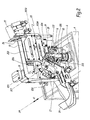
figure 1 is a partial perspective view of a honing machine according to the invention in a loading configuration, -
figure 2 is a perspective view similar tofigure 1 , when the honing machine is in a honing configuration, -
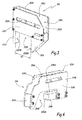
figure 3 is a perspective view of a first transfer box, which belongs to a transfer mechanism of the honing machine offigure 1 , -
figure 4 is a perspective view of a second transfer box, which belongs to the same transfer mechanism, -
figure 5 is a partial front view of the machine offigures 1 and2 , where some parts are omitted, for the sake of clarity, -
figure 6 is a front view similar tofigure 5 , at a smaller scale and where some side panels have been removed in order to show the bearing rings in the transfer mechanism, -
figure 7 is a front view similar tofigure 6 where, for the sake of clarity only two bearing rings are represented in the machine, which is in the configuration offigures 5 and6 , -
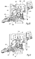
figures 8 to 14 are front views similar tofigure 6 when the transfer mechanism of the honing machine is in successive configurations, -
figure 15 is an enlarged detailed view of a workpiece holder of the machine offigures 1 to 14 , when this workpiece holder is in the configuration offigure 13 , -
figure 16 is a perspective view of the workpiece holder in the configuration offigure 15 , -
figure 17 is an enlarged view, similar tofigure 15 when the workpiece holder is in the configuration offigure 14 , -
figure 18 is a perspective view of the workpiece holder in the configuration offigure 17 , in a direction close to the one offigure 16 , and -
figure 19 is a perspective view of the workpiece holder, in the configuration offigures 17 and18 , in another direction. - The
honing machine 2 represented onfigures 1 to 19 includes abase frame 4 which supports a fixedpole 6. Ahoning stone 8 is supported by anarm 10 which extends upwardly fromfixed bracket 6. -
Honing machine 2 also includes amovable frame 12 slidable, with respect tobase frame 4, along a fixed longitudinal axis X4, in two opposite directions, as shown by double arrow A1. A non-represented actuator, such as an electric motor or a pneumatic or hydraulic cylinder, drivesmovable frame 12 in translation along axis X4. -
Movable frame 12 supports ahoning station 14 where abearing ring 100 is held in position for interaction with thehoning stone 8. More precisely,movable frame 12 supports a rotary actuator, in the form of anelectric motor 16, which is adapted to drive bearingring 100 present in holdingstation 14 around a rotation axis X14 which is fixed with respect to frame 12 and parallel to axis X4.Movable frame 12 supports aholding mechanism 17 provided with tworollers 172 adapted to come into contact with a lateral surface of bearing ring and to push this ring towardselectric motor 16, in order to make a friction type connection between bearingring 100 and a rotatingmember 162 driven bymotor 16 in rotation around axis X14. Actually, holdingmechanism 17 is movable with respect to frame 12, in translation along an axis X17 parallel to axes X4 and X14, between a loading configuration of honingmachine 2 represented onfigure 1 and a honing configuration represented onfigure 2 . In the configuration offigure 1 ,rollers 172 do not contactbearing ring 100 whereas, in the configuration offigure 2 ,rollers 172push bearing ring 100 against rotatingmember 162. - In the following description, unless otherwise specified, one considers honing
machine 2 in its loading configuration. For the sake of clarity,items 4 to 10 and 17 are omitted onfigures 5 to 14 . - Honing
station 14 includes, amongst others, aworkpiece holder 18 which has aconcave surface 182, with a section perpendicular to axis X14 in the form of an arc of a circle centered on axis X14. This workpiece holder is selected in order to match the outer dimensions of bearing rings to be processed by honingmachine 2. Thus, workpiece holder is generally changed when a new type of bearing rings is to be processed in honingmachine 2. - Honing
machine 2 also includes atransfer mechanism 20 which is used to successively feed honingstation 14 with bearing rings stored in aninlet chute 22. -
Transfer mechanism 20 includes afirst transfer box 202 and asecond transfer box 204 which is located immediately below the first transfer box. - In the present description, the words "below", "above", "inferior" or "superior" relate to a working configuration of honing
machine 2. "Above" or "superior" relates a surface or a part which is oriented towards the top ofmachine 2 in such a configuration, whereas "below" or "inferior" relates to a surface or a part which is oriented to the bottom of this machine. -
First transfer box 202 is visible alone onfigure 3 and includes a firstmetallic side wall 2020 and a secondmetallic side wall 2022. Twospacers side walls first transfer box 202 is defined betweenside walls inspection window 2028 is provided onside wall 2022 and allows checking the content of volume V202 throughside wall 2022. -
Spacer 2024 extends on the whole height ofside walls Spacer 2026 extends between lower parts ofside walls inlet opening 202A is defined on the lateral side ofbox 202 visible onfigure 2 . This inlet opening 202A allows introduction of a bearing ring within volume V202. Moreover, an outletbottom opening 202B is defined between the lower edges ofside walls spacers - 2026A denotes the upper surface of
spacer 2026. Thisupper surface 2026A is inclined towards outlet opening 202B. In other words, this surface lowers in the direction ofoutlet opening 202B. - 2024B and 2026B respectively denote the vertical surfaces of
spacers outlet opening 202B is defined betweensurfaces surfaces -
Second transfer box 204 also includes twometallic side walls synthetic spacers inspection window 2048 is provided inside wall 2042 and allows inspection of the inside volume V204 ofsecond transfer box 204. An inlet opening 204A ofsecond transfer box 204 is defined between the top edges ofside walls second transfer box 204 is defined betweenspacers side walls - 2046A denotes the upper surface of
spacer 2046. This surface is horizontal. - 2046B denotes an end face of spacer 2046 oriented towards
spacer 2044.Outlet opening 204B is defined, along axis Y204, betweenspacer 2044 and endface 2046B. - In working configurations of
transfer mechanism 20,inlet opening 204A is vertically aligned withoutlet opening 202B, so that a bearing ring can go from volume V202 into inside volume V204 by gravity. -
Transfer mechanism 20 also includes a firstpneumatic cylinder 206 mounted onframe 12 and adapted to drivefirst transfer box 202 in translation along an axis Y202 which is horizontal and perpendicular to axis X4. Double arrow A2 represents the to-and-fro movements offirst transfer box 202 in the direction of axis Y202.Cylinder 206 is a rodless cylinder whose output member is connected tofirst transfer box 202. - A second
pneumatic cylinder 208 is mounted onmovable frame 12 and its output member is connected tosecond transfer box 204 and drives this box in translation along a second axis Y204 which is parallel to axis Y202. Double arrow A4 shows the to-and-fro movements ofsecond transfer box 204 along axis Y204. - Honing
machine 2 also includes aninlet chute 22 and anoutlet chute 24. Inmachine 2, bearing rings go frominlet chute 22 tooutlet chute 24 viatransfer mechanism 20 and honingstation 14. -
Outlet chute 24 is provided with aside wall 242 and aninductive sensor 244 which allows detecting the presence of a bearing ring in an inside volume V24 ofchute 24, when the ring lies or rolls on alower surface 246 ofoutlet chute 24. - For the sake of clarity,
side walls figures 6 to 14 , in order to show inside volumes V202, V204 and V24 and their content. - An
inlet gate 26 is arranged betweeninlet chute 22 andtransfer mechanism 20 and this inlet gate is controlled by apneumatic cylinder 28. - In this example,
cylinders items - As shown on
figures 15 to 19 ,workpiece holder 18 is equipped with twopads concave surface 182, by a few tenth of millimeters, so as to make sure that each bearing ring will touch only the pads and thereby be accurately positioned.Pad 184 is located in the lower part of honingstation 14, below bearingring 100 present in this station.Pad 184 is substantially aligned, along a vertical direction, with axis X14.Pad 186 is located on a side of honingstation 14, actually on the same side asinlet chute 22, roughly at the same height as axis X14. The shape ofworkpiece holder 18, in particular the radius of curvature ofconcave surface 182 and the location ofpads machine 2. - The exposed
surface pad armature armature figures 15 and17 , the thickness of the high stiffnesslayers forming surfaces - A through
hole 188 is provided onworkpiece holder 18 and extends vertically and downwardly from a steppedportion 182A ofconcave surface 182. Throughhole 188 is visible onfigure 15 via a local cutaway ofworkpiece holder 18, which is metallic. - Z188 denotes the central axis of through
hole 188. Ametallic pin 190 is slidably mounted within throughhole 188 and movable along axis Z188 between a first position, represented onfigures 15 and16 , and a second position, represented onfigures 17 to 19 .Pin 190 has anupper head 192 with anupper surface 192A adapted to be in contact with a lower portion of the outer radial surface of bearingring 100 present in honingstation 14, as explained here-under. Pin 190 also has a lower sole 194 which defines aperipheral shoulder 196 around the main portion ofpin 190. Acoil spring 280 is mounted aroundpin 190, betweenshoulder 196 and alower surface 183 ofworkpiece holder 18. - As shown on
figures 15 and16 , whenpin 190 is in its first position, itshead 192 protrudes upwardly with respect tosurface 184A ofpad 184. Thus,head 192 ofpin 190 is on the path of a bearing ring falling towardsworkpiece holder 18. As shown onfigures 17 to 19 , whenpin 190 is in its second position,upper surface 192A ofhead 192 does not protrude abovesurface 184A. In this position,surface 192A is slightly belowsurface 184A, so that a bearing ring lying onworkpiece holder 18 does not contactpin 190. In other words, in this second position, pin 190 is out of reach of a ring present in honingstation 14. - A
shaft 30 is mounted onmovable frame 12 next toworkpiece holder 18 and its longitudinal axis Y30 is parallel to axes Y202 and Y204. Actually,shaft 30 is rotatably supported bymovable frame 12, so that it can rotate around axis Y30 between a first position, represented onfigures 15 and16 , and a second position, represented onfigures 17 to 19 . - A
first end 302 ofshaft 30 is equipped with apaddle 304 which extends radially with respect to axis Y30, so that it is located directly below sole 194 in the configuration offigures 15 and16 . More precisely, in this configuration, sole 194 lies against anupper surface 306 ofpaddle 304. - The
second end 308 ofshaft 30, which is opposite tofirst end 302, is connected to arocker arm 310. The end ofrocker arm 310 opposite toshaft 30 is connected to anoutput rod 320 of agas cylinder 32. Thus,gas cylinder 32 forms an actuator which allows pivotingshaft 30, in rotation around axis Y30, between the position offigures 15 and16 , on the one hand, and the position offigures 17 to 19 , on the other hand.Gas cylinder 32 can also be used to dampen a rotation movement ofshaft 30 around axis Y30, in the direction of arrow R1 onfigure 16 , as explained here-below. - A non-represented pneumatic control unit is connected to
cylinders - Feeding of honing
station 14 is now explained in connection tofigures 5 to 19 . - On these figures, a bearing ring present in honing
station 14 is referenced 100, whereas a bearing ring to be fed to honingstation 14 is referenced 102.Figure 6 shows two bearingrings 102 intransfer mechanism 20 but, for the sake of clarity, only onebearing ring 102 is represented onfigures 7 to 14 . The configuration of honingmachine 2 is the same onfigures 6 and 7 . In this configuration, bearingring 100 is present in honingstation 14 and centered on axis X14, in front ofrotary member 162.Inlet gate 26 has been opened bycylinder 28 andbearing ring 102 enters inside volume V202 offirst transfer box 202 viainlet opening 202A. In this configuration, bearingring 102 rolls onupper surface 2026A ofspacer 2026 and falls within inside volume V204 ofsecond transfer box 204 via outlet opening 202B ofbox 202 and inlet opening 204A ofbox 204. In other words, and as shown by arrow A7 onfigure 7 and by the comparison offigures 7 and8 , bearingring 102 goes, by gravity, from inside volume V202 into inside volume V204. - Thus, inside volume V202 of
first transfer box 202 accommodates bearingring 102 until it falls down into inside volume V204 ofsecond transfer box 204. In the configuration offigure 8 , and actually also in the configuration offigures 9 to 12 , volume V204 accommodates most ofbearing ring 102, but a top part of the ring remains in volume V202. - In the configuration of
figure 8 , bearingring 102 is blocked within volume V204, and actually protrudes upwardly into volume V202 sincering 102 lies on theupper surface 2046A ofspacer 2046. Thus,space 2046 works as a platform for supportingbearing ring 102 within volume V204. Moreover,ring 102 is located, along axis Y202, betweenspacers transfer box 202 is designed so that distance D2 is slightly larger than the outside diameter ofring 102. Thus, in the configuration offigure 8 ,ring 102 is guided betweenvertical surfaces ring 102 does not interfere with bearingring 100 because the opening defined betweenspacers ring 102 to move downwardly by gravity. - From the configuration of
figure 8 ,second transfer box 204 is moved along axis Y204 bycylinder 208, in the direction of arrows A8 and A9 onfigures 8 and 9 , so that it reaches the position offigure 9 . In this position ofsecond transfer box 204, itsbottom outlet opening 204B is laterally offset from honingstation 14. - Due to the movement of
second transfer box 204 between the configuration offigure 8 and the configuration offigure 9 , bearingring 100 is ejected from honingstation 14 by theend face 2046B ofspacer 2046. Then, ring 200 falls within the inside volume V24 ofoutlet chute 24. During the movement ofsecond transfer box 204 in the direction of arrows A8 and A9, bearingring 102 rolls onupper surface 2046A of platform orspacer 2046. -
Cylinder 206 is piloted in a next step in order to movefirst transfer box 202 along axis Y202 in the same direction assecond transfer box 204 has been moved previously, as shown by arrow A10 onfigure 10 . Because of the translation movement offirst transfer box 202, spacer 2026 works as a pusher for pushingbearing ring 102 in the same direction, towardsspacer 2044, within inside volume V204 and along axis Y204. On this occasion, bearingring 102 rolls onsurface 2046A. This movement offirst transfer box 202 goes on up to a point whereoutlet opening 202B is vertically aligned with honingstation 14, along a vertical axis Z14 which crosses axis X14, as shown onfigures 10 and 11 . This movement offirst transfer box 202 results in movingbearing ring 102 towardsbottom outlet opening 204B. - The platform formed by
spacer 2046 temporary holds bearingring 102 within inside volume V204, from the configuration offigure 8 to the configuration offigure 11 . - As shown on
figures 10 and 11 , bearingring 100 rolls onsurface 246 withinchute 24 and passes in front ofinductive sensor 244, so that the ejection of bearingring 100 from rollingstation 14 is automatically detected. - Once this detection has occurred, it is sure that no bearing ring remains in honing
station 14, so that this honing station can be loaded again with bearingring 102. To this end,second transfer box 204 is moved along axis Y204 in the opposite direction, as shown by arrow A12 onfigure 2 , that is in a direction opposite to the movement offirst transfer box 202 in the previous step. This bringstransfer mechanism 20 in a configuration whereoutlet openings second transfer boxes station 14. This is the configuration represented onfigure 12 . - From this configuration and because of gravity,
ring 102 falls into honingstation 14, as shown by arrow A13 onfigures 12 and 13 . In other words, bearingring 102 follows a vertical downward path or trajectory, from volume V204 to honingstation 14, this path being shown by arrow A13 onfigures 12 and 13 . - The downward movement of
ring 10 is dampened bypin 190, which protrudes upwardly frompad 184 on the downward path of bearingring 102, sinceworkpiece holder 18 is in the configuration offigures 15 and16 . When bearingring 102 reaches head 192 ofpin 190, it exerts a downward effort E102, as represented onfigures 15 and16 , which is transmitted bypin 190 to paddle 304 and tends to rotateshaft 30 around axis Y30, in the direction of rotation arrow R1. This rotation movement ofshaft 30 around its longitudinal axis is transmitted byrocker arm 310 torod 320 ofgas cylinder 32. In other words, effort E102 is transmitted as a pulling effort E'102 onrod 32, this pulling effort being dampened or slowed by the gas pressure withincylinder 32. Thus,shaft 30 andgas cylinder 32 work as braking means forpin 190, when it goes from its position offigures 15 and16 to a lower position. - Once this dampening or braking effect of the downward movement of
ring 102 has been obtained with the damper formed ofpin 190,shaft 30 andcylinder 32,cylinder 32 is actuated to pushrod 320 outwardly, so thatrocker arm 310 andshaft 30 are brought into the configuration offigures 16 to 19 wherepaddle 304 is offset frompin 190. In other words,shaft 30 is brought bygas cylinder 32 androcket arm 310 from a first angular position with respect to axis Y30 to a second angular position. In the first angular position ofshaft 30,paddle 304 is in contact with sole 194, so thatpaddle 304 interacts with the downward movement ofpin 190 going from its first position to its second position. More precisely, whenshaft 30 is in its first angular position, paddle 304 lies on the downward vertical path of sole 194 whenpin 190 moves from its first position to its second position. Because of the biasing effort ofspring 280, sole 194 is in contact withpaddle 304 as long asshaft 30 remains in its first angular position. In the second angular position ofshaft 30,paddle 304 is out of reach of sole 194, so thatshaft 30 does not interact withpin 190 which is only subjected to its weight and to the action ofspring 280. Thus, pin 190 automatically reaches its second position wheresurface 192A is belowsurface 184A.Spring 280 pushes sole 194 away fromsurface 183, so thathead 192 comes into contact withsurface portion 182A, to the point that head 192 does not protrude upwardly with respect tosurface 184A ofpad 184, as explained here-above. - Then ring 102 reaches the configuration of
figure 14 where it is centered on axis X14 within honingstation 14. In this configuration, centering ofring 102 with respect to axis X14 is obtained viapads - In other words, thanks to the use of
pin 190,shaft 30 andgas cylinder 32, it is possible to usehigh resistance pads pads ring 102. - In the configuration of
figure 14 ,ring 102 is ready for being pushed by holdingmechanism 17 against rotatingmember 162, so that it can be driven in rotation around axis X14 byelectric motor 16 oncemovable frame 12 has been moved along axis X4 in order to align, along axis X4, the inner radial surface ofring 102, now present in honingstation 14, with honingstone 8. - At a later stage, which corresponds to the configuration of
figure 11 , that is when a bearing ring has just been ejected from honingstation 14,gas cylinder 32 actuatesrocker arm 310 to bringshaft 30 back to its first position, which bringspin 190 back to its position offigures 12 to 16 . - Throughout the process described here-above,
inspection windows ring 102 intransfer mechanism 20.
Claims (15)
- Honing machine (2) for bearing rings (100, 102), this machine including:- a frame (12),- a honing tool (8),- a honing station (14) for holding a bearing ring in position with respect to the honing tool, the honing station including a workpiece holder (18) with a concave surface (182) equipped with at least one pad (184, 186) for supporting a bearing ringcharacterized in that the workpiece holder (18) is equipped with a damper (30, 32, 190) movable between a first active configuration, where it protrudes on a path of a bearing ring (102) moving towards the workpiece holder (18) in the honing station (14), and a second passive configuration, where it is out of reach of a bearing ring in the honing station.
- A honing machine according to claim 1, characterized in that each pad (184, 186) of the workpiece holder is coated with a high stiffness material, in particular with a layer of polycrystalline diamond.
- A honing machine according to any preceding claim, characterized in that the damper includes a pin (190), which is movable in translation along a vertical axis (Z188), and damping means (30, 32) for braking a vertical downward displacement of the pin.
- A honing machine according to claim 3, characterized in that the pin (190) is movable along the vertical axis (Z188) between a first position, where it protrudes upwardly with respect to an adjacent pad (184) of the workpiece holder, and a second position, where an upper surface (192A) of the pin is below an upper surface (184A) of the adjacent pad.
- A honing machine according to claim 4, characterized in that the damping means include:- a rotable shaft (30) movable in rotation (R1) around its longitudinal axis (Y30), between a first angular position where it interacts with a vertical downward movement of the pin (190), between its first and second positions, and a second angular position where the shaft is out of reach of the pin and- a gas cylinder (32) for moving the shaft between its first and second positions, and reverse.
- A honing machine according to claim 5, characterized in that the shaft (30) is provided with a paddle (304) which lies on the downward path of the pin (190) between its first and second positions, when the shaft is in its first angular position, and which is away from the downward path, when the rotating shaft is in its second angular position.
- A honing machine according to claim 6, characterized in that the paddle (304) is secured to a first (302) end of the shaft (30) and the gas cylinder (32) is connected by a rocker arm (310) to a second end (308), opposite to the first end, of the shaft.
- A honing machine according to any one of claims 5 to 7, characterized in that it includes elastic means (280) for biasing the pin (190) downwardly.
- A honing machine according to claim 8, characterized in that the elastic means (280) bias the pin (190) against the paddle (304) when the rotating shaft (30) is in its first angular position.
- A honing machine according to one of claims 8 and 9, characterized in that the elastic means is a coil spring (280) mounted around the pin (190) and compressed between a lower surface (183) of the workpiece holder (18) and a peripheral shoulder (196) of the pin.
- A honing machine according to one of claims 3 to 10, characterized in that the workpiece (18) is provided with a vertical through hole (188) and the pin (190) is slidably movable inside the vertical through hole.
- A honing machine according to one of claims 3 to 11, characterized in that- the pin (190) has an upper head (192) for receiving an outer surface of a bearing ring (102),- the concave surface (182) of the workpiece holder (18) has a stepped portion, which is below an exposed surface (184A) of an adjacent pad (184) and- the upper head of the pin is accommodated above the stepped portion of the upper surface of the workpiece holder and at a level below the upper surface of the adjacent pad, when the damper (30, 32, 190) is in its second passive configuration.
- A honing machine according to any preceding claim, characterized in that it includes a transfer mechanism (20) for feeding the honing station (14) with bearing rings, one after the other, the transfer mechanism including- a first transfer box (202), adapted to accommodate a bearing ring (102) and movable in translation, in a to-and-fro (A2) movement with respect to the frame (12), along a first axis (Y202),- a second transfer box (204), adapted to accommodate a bearing ring and movable in translation, in a to-and-fro movement (A4) with respect to the frame, along a second axis (Y204) parallel to the first axis,- first driving means (206) for driving the first transfer box in translation along the first axis and- second driving means (208) for driving the second transfer box in translation along the axis direction,in such a way that the second transfer box (204) is located under and adjacent the first transfer box (202), above the honing station (14), and that the second transfer box has a top inlet opening (204A) which is vertically aligned with a bottom outlet opening (202B) of the first transfer box.
- Method for feeding a honing station (14) of a honing machine (2) according to any preceding claim with a bearing ring (102), characterized in that it includes at least the following steps consisting in:a) setting the damper (30, 32, 190) in its first active configurationb) introducing the bearing ring by gravity into the honing station (14) up to a point where it contacts the damperc) setting the damper in its second passive configuration
- A method according to claim 14, characterized in that the honing machine is according to one of claims 3 to 13 and, during step c), an upper portion (192) of the pin (190) is moved downwardly by gravity up to a level where it is below an exposed surface (184A) of an adjacent pad (184) of the workpiece holder (18).
Priority Applications (2)
| Application Number | Priority Date | Filing Date | Title |
|---|---|---|---|
| EP15305316.0A EP3064316A1 (en) | 2015-03-02 | 2015-03-02 | Honing machine for bearing rings and method for feeding such a machine with bearing rings |
| US15/016,482 US20160256974A1 (en) | 2015-03-02 | 2016-02-05 | Honing machine for bearing rings and method for feeding such a machine with bearing rings |
Applications Claiming Priority (1)
| Application Number | Priority Date | Filing Date | Title |
|---|---|---|---|
| EP15305316.0A EP3064316A1 (en) | 2015-03-02 | 2015-03-02 | Honing machine for bearing rings and method for feeding such a machine with bearing rings |
Publications (1)
| Publication Number | Publication Date |
|---|---|
| EP3064316A1 true EP3064316A1 (en) | 2016-09-07 |
Family
ID=52684172
Family Applications (1)
| Application Number | Title | Priority Date | Filing Date |
|---|---|---|---|
| EP15305316.0A Withdrawn EP3064316A1 (en) | 2015-03-02 | 2015-03-02 | Honing machine for bearing rings and method for feeding such a machine with bearing rings |
Country Status (2)
| Country | Link |
|---|---|
| US (1) | US20160256974A1 (en) |
| EP (1) | EP3064316A1 (en) |
Cited By (3)
| Publication number | Priority date | Publication date | Assignee | Title |
|---|---|---|---|---|
| KR102146574B1 (en) * | 2020-03-20 | 2020-08-20 | 심조원 | Innerring grinding equipment |
| CN117798722A (en) * | 2024-02-29 | 2024-04-02 | 江苏帝蒙德轴承有限公司 | Rolling bearing ring processingequipment |
| CN120886133A (en) * | 2025-08-18 | 2025-11-04 | 江苏信实精密工具有限公司 | Diamond roller grinding equipment for fine treatment of inner hole walls |
Families Citing this family (2)
| Publication number | Priority date | Publication date | Assignee | Title |
|---|---|---|---|---|
| CN114800009B (en) * | 2022-04-12 | 2024-04-23 | 银川金沃精工科技有限公司 | Bearing outer ring overturning detection and removal device, turning production line and machining method |
| CN115847204B (en) * | 2022-12-26 | 2025-07-15 | 进发轴承有限公司 | A sealed bearing inner ring processing device |
Citations (9)
| Publication number | Priority date | Publication date | Assignee | Title |
|---|---|---|---|---|
| US3339312A (en) * | 1964-05-18 | 1967-09-05 | Fafnir Bearing Co | Honing apparatus |
| GB1087954A (en) * | 1964-06-13 | 1967-10-18 | Zd Y Presneho Strojirenstvi Go | Feeding apparatus for supplying round parts to an automatic machine tool |
| US3503154A (en) * | 1966-01-08 | 1970-03-31 | Supfina Wieck & Hentzen | Apparatus for the precision machining of annular workpieces |
| DE2326689A1 (en) * | 1973-05-25 | 1974-12-05 | Grieshaber Metallwarenfab Geb | FINE PROCESSING MACHINE |
| US4136488A (en) * | 1977-08-29 | 1979-01-30 | Ex-Cell-O Corporation | Honing machine |
| SU1237376A1 (en) * | 1984-05-23 | 1986-06-15 | Всесоюзный конструкторско-технологический институт строительного и дорожного машиностроения | Loading/unloading arrangement |
| US5161332A (en) * | 1990-02-24 | 1992-11-10 | Gmn Georg Muller Nurnberg Ag | Chucking apparatus for the combined working of rolling bearing rings |
| US20100323590A1 (en) * | 2006-12-28 | 2010-12-23 | Robotic Consulting S.A.R.L. | Grinding machine for bearing rings |
| DE102010036470A1 (en) * | 2010-07-16 | 2012-01-19 | Thielenhaus Technologies Gmbh | Device for honing e.g. conical running surfaces, of roller bearing ring of large bearing, has eccentric cam drive for creation of oscillating movements of tool base support, where tool base support includes adjustable tool connector |
-
2015
- 2015-03-02 EP EP15305316.0A patent/EP3064316A1/en not_active Withdrawn
-
2016
- 2016-02-05 US US15/016,482 patent/US20160256974A1/en not_active Abandoned
Patent Citations (9)
| Publication number | Priority date | Publication date | Assignee | Title |
|---|---|---|---|---|
| US3339312A (en) * | 1964-05-18 | 1967-09-05 | Fafnir Bearing Co | Honing apparatus |
| GB1087954A (en) * | 1964-06-13 | 1967-10-18 | Zd Y Presneho Strojirenstvi Go | Feeding apparatus for supplying round parts to an automatic machine tool |
| US3503154A (en) * | 1966-01-08 | 1970-03-31 | Supfina Wieck & Hentzen | Apparatus for the precision machining of annular workpieces |
| DE2326689A1 (en) * | 1973-05-25 | 1974-12-05 | Grieshaber Metallwarenfab Geb | FINE PROCESSING MACHINE |
| US4136488A (en) * | 1977-08-29 | 1979-01-30 | Ex-Cell-O Corporation | Honing machine |
| SU1237376A1 (en) * | 1984-05-23 | 1986-06-15 | Всесоюзный конструкторско-технологический институт строительного и дорожного машиностроения | Loading/unloading arrangement |
| US5161332A (en) * | 1990-02-24 | 1992-11-10 | Gmn Georg Muller Nurnberg Ag | Chucking apparatus for the combined working of rolling bearing rings |
| US20100323590A1 (en) * | 2006-12-28 | 2010-12-23 | Robotic Consulting S.A.R.L. | Grinding machine for bearing rings |
| DE102010036470A1 (en) * | 2010-07-16 | 2012-01-19 | Thielenhaus Technologies Gmbh | Device for honing e.g. conical running surfaces, of roller bearing ring of large bearing, has eccentric cam drive for creation of oscillating movements of tool base support, where tool base support includes adjustable tool connector |
Cited By (4)
| Publication number | Priority date | Publication date | Assignee | Title |
|---|---|---|---|---|
| KR102146574B1 (en) * | 2020-03-20 | 2020-08-20 | 심조원 | Innerring grinding equipment |
| CN117798722A (en) * | 2024-02-29 | 2024-04-02 | 江苏帝蒙德轴承有限公司 | Rolling bearing ring processingequipment |
| CN117798722B (en) * | 2024-02-29 | 2024-05-28 | 江苏帝蒙德轴承有限公司 | Rolling bearing ring processingequipment |
| CN120886133A (en) * | 2025-08-18 | 2025-11-04 | 江苏信实精密工具有限公司 | Diamond roller grinding equipment for fine treatment of inner hole walls |
Also Published As
| Publication number | Publication date |
|---|---|
| US20160256974A1 (en) | 2016-09-08 |
Similar Documents
| Publication | Publication Date | Title |
|---|---|---|
| EP3064317A1 (en) | Honing machine for bearing rings and method for feeding such a machine with bearing rings | |
| US20160256974A1 (en) | Honing machine for bearing rings and method for feeding such a machine with bearing rings | |
| EP2351629B1 (en) | Centering device and centering method | |
| US20100323590A1 (en) | Grinding machine for bearing rings | |
| CN106040605B (en) | A kind of preceding detection process system of steel pipe manufacture | |
| CN101311854B (en) | Measuring and controlling method and its device for machine for cutting tubes | |
| CN105973178B (en) | A kind of preceding detection process method of steel pipe manufacture | |
| KR20110060064A (en) | Rapid loading and unloading system for machine tools | |
| KR101433854B1 (en) | Apparatus for measuring gap of roll bearing in continuous casting machine | |
| US20150306723A1 (en) | Grinding machine for bearing rings and method for moving a bearing ring in such a machine | |
| US6758729B2 (en) | Centrifugal barrel finishing apparatus | |
| CN106694930A (en) | High-speed drilling electromagnetic suction cup type workpiece damping machining method | |
| US20220314299A1 (en) | Workpiece ejecting system for use in stamping machine | |
| CN115533336B (en) | Drill rod cutting device | |
| CN120363040A (en) | Automatic feeding and discharging mechanism for ball screw support bearing fine grinding | |
| US20150306735A1 (en) | Grinding machine with liquid coolant injection nozzle | |
| EP2990388A1 (en) | Cutting head for use in a cutting device | |
| CN109690275A (en) | For the device and method by balance weight placement on the stationary plane on the inside of wheel hub | |
| US10105759B2 (en) | Method and apparatus for producing a rod-like body | |
| CN206720295U (en) | bar image detection cam mechanism | |
| US4856232A (en) | Workpiece carrier means for surface grinding machine | |
| CN104399797A (en) | Steel tube spinning lathe and steel tube machining process utilizing spinning lathe | |
| CN215033238U (en) | Automatic discharging device of ring rolling machine | |
| KR100771831B1 (en) | Rolling Roll Grinding Machine | |
| JP7391347B2 (en) | Movement devices for objects, especially balance devices |
Legal Events
| Date | Code | Title | Description |
|---|---|---|---|
| PUAI | Public reference made under article 153(3) epc to a published international application that has entered the european phase |
Free format text: ORIGINAL CODE: 0009012 |
|
| AK | Designated contracting states |
Kind code of ref document: A1 Designated state(s): AL AT BE BG CH CY CZ DE DK EE ES FI FR GB GR HR HU IE IS IT LI LT LU LV MC MK MT NL NO PL PT RO RS SE SI SK SM TR |
|
| AX | Request for extension of the european patent |
Extension state: BA ME |
|
| STAA | Information on the status of an ep patent application or granted ep patent |
Free format text: STATUS: THE APPLICATION IS DEEMED TO BE WITHDRAWN |
|
| 18D | Application deemed to be withdrawn |
Effective date: 20170308 |