EP3063432B1 - Method for manufacturing a transverse segment for a pushbelt for a continuously variable transmission and a transverse segment thus obtained - Google Patents
Method for manufacturing a transverse segment for a pushbelt for a continuously variable transmission and a transverse segment thus obtained Download PDFInfo
- Publication number
- EP3063432B1 EP3063432B1 EP14798725.9A EP14798725A EP3063432B1 EP 3063432 B1 EP3063432 B1 EP 3063432B1 EP 14798725 A EP14798725 A EP 14798725A EP 3063432 B1 EP3063432 B1 EP 3063432B1
- Authority
- EP
- European Patent Office
- Prior art keywords
- transverse segment
- basic material
- process step
- transverse
- cutting method
- Prior art date
- Legal status (The legal status is an assumption and is not a legal conclusion. Google has not performed a legal analysis and makes no representation as to the accuracy of the status listed.)
- Not-in-force
Links
- 238000000034 method Methods 0.000 title claims description 81
- 238000004519 manufacturing process Methods 0.000 title description 15
- 230000005540 biological transmission Effects 0.000 title description 10
- 239000000463 material Substances 0.000 claims description 71
- 238000005520 cutting process Methods 0.000 claims description 20
- 239000000969 carrier Substances 0.000 claims description 8
- 230000007704 transition Effects 0.000 description 26
- 230000008602 contraction Effects 0.000 description 6
- 230000001154 acute effect Effects 0.000 description 3
- 230000002349 favourable effect Effects 0.000 description 2
- 238000000926 separation method Methods 0.000 description 2
- 230000001627 detrimental effect Effects 0.000 description 1
- 238000006073 displacement reaction Methods 0.000 description 1
- 238000009826 distribution Methods 0.000 description 1
- 230000000694 effects Effects 0.000 description 1
- 239000012467 final product Substances 0.000 description 1
- 238000007689 inspection Methods 0.000 description 1
- 238000012986 modification Methods 0.000 description 1
- 230000004048 modification Effects 0.000 description 1
- 239000000047 product Substances 0.000 description 1
- 238000004080 punching Methods 0.000 description 1
- 239000004575 stone Substances 0.000 description 1
Images


Classifications
-
- F—MECHANICAL ENGINEERING; LIGHTING; HEATING; WEAPONS; BLASTING
- F16—ENGINEERING ELEMENTS AND UNITS; GENERAL MEASURES FOR PRODUCING AND MAINTAINING EFFECTIVE FUNCTIONING OF MACHINES OR INSTALLATIONS; THERMAL INSULATION IN GENERAL
- F16G—BELTS, CABLES, OR ROPES, PREDOMINANTLY USED FOR DRIVING PURPOSES; CHAINS; FITTINGS PREDOMINANTLY USED THEREFOR
- F16G5/00—V-belts, i.e. belts of tapered cross-section
- F16G5/16—V-belts, i.e. belts of tapered cross-section consisting of several parts
-
- B—PERFORMING OPERATIONS; TRANSPORTING
- B21—MECHANICAL METAL-WORKING WITHOUT ESSENTIALLY REMOVING MATERIAL; PUNCHING METAL
- B21D—WORKING OR PROCESSING OF SHEET METAL OR METAL TUBES, RODS OR PROFILES WITHOUT ESSENTIALLY REMOVING MATERIAL; PUNCHING METAL
- B21D28/00—Shaping by press-cutting; Perforating
- B21D28/02—Punching blanks or articles with or without obtaining scrap; Notching
-
- B—PERFORMING OPERATIONS; TRANSPORTING
- B21—MECHANICAL METAL-WORKING WITHOUT ESSENTIALLY REMOVING MATERIAL; PUNCHING METAL
- B21D—WORKING OR PROCESSING OF SHEET METAL OR METAL TUBES, RODS OR PROFILES WITHOUT ESSENTIALLY REMOVING MATERIAL; PUNCHING METAL
- B21D53/00—Making other particular articles
- B21D53/14—Making other particular articles belts, e.g. machine-gun belts
Definitions
- This disclosure relates to a method for manufacturing a transverse segment that is destined to be part of a pushbelt for a continuously variable transmission.
- a pushbelt for a continuously variable transmission is commonly known.
- Such a pushbelt usually comprises at least one, but usually two bundles of continuous bands or rings that carry a number of transverse segments.
- the transverse segments are movably arranged along the entire circumference of the bands and transmit forces that are related to the operation of the transmission wherein the pushbelt is provided.
- a longitudinal direction of the transverse segment corresponds to a circumferential direction of the pushbelt.
- a vertical transverse or height direction of the transverse segment corresponds to a radial direction of the pushbelt.
- a horizontal transverse direction or width direction of the transverse segment corresponds to a direction perpendicular to both the longitudinal direction and the vertical transverse direction.
- the transverse segment In the horizontal direction, the transverse segment is on both sides provided with openings for at least partially receiving the bundles of bands.
- the transverse segment comprises carrying surfaces that are formed by the radial inside or lower boundary of the openings.
- the transverse segment is on both sides, as seen in the horizontal direction, provided with pulley sheave contact surfaces, which are divergent in the direction of the carrying surfaces.
- the transverse segment comprises successively a base portion, a middle portion of which the dimensions in the horizontal direction are smaller than those of the base portion, and a top portion of which the dimensions in the horizontal direction at the location of the connection to the middle portion are larger than those of the middle portion.
- the basis portion comprises the carrying surfaces and the pulley sheave contact surfaces.
- the base portion is located at the side of the inner circumference of the pushbelt, whereas the top portion is located at the side of the outer circumference of the pushbelt.
- An important function of the middle portion is interconnecting the base portion and the top portion.
- the transverse segment has two main body surfaces, namely a front surface and a back surface, which extend substantially parallel with respect to each other, substantially perpendicular to the longitudinal direction. At least a part of the front surface of the transverse segment is designed to abut against at least a part of the back surface of a subsequent transverse segment in the pushbelt, whereas at least a part of the back surface of the transverse segment is designed to abut against at least a part of the front surface of a previous transverse segment in the pushbelt.
- two adjacent transverse segments can be rotated relative to one another about a rocking edge of one such segment, which rocking edge is usually defined at the front surface of each transverse segment and extends over the entire width of the transverse segment.
- the rocking edge is formed as a convexly curved area of the front surface, which area separates two portions of said front surface that are oriented at an angle relative to one other.
- An important function of the rocking edge is to provide the mutual contact between adjacent transverse segments that are located between the pulley sheaves of a pulley.
- the rocking edge is intended to arrange that the forces which are related to a movement of the pushbelt are transmitted from any transverse segment to a subsequent transverse segment in a controlled manner.
- the transverse segment is typically manufactured from a strip of basic material in a known blanking process by means of a blanking device.
- the transverse segment is cut and shaped from basic material in a number of subsequent steps.
- the openings for at least partially receiving the bundles of bands are punched out in two steps. Firstly, these openings are roughly shaped by punching holes in the basic material that are somewhat smaller in size than the final size of the said openings.
- the openings and thus also the carrying surfaces of the transverse segment are finally and accurately shaped by cutting away excess material along the edge of the punched holes.
- the punch is pressed into and ultimately through the basic material under the influence of a cutting force, while the ejector also acts on the basic material and in line with the punch, however, on the opposite side of the basic material.
- the part of the basic material that will form the transverse segment is clamped between the punch and the ejector and together these three parts move relative to the guide plate and die and the part of the basic material located between these latter two blanking device component parts.
- the front surface of the transverse segment including the rocking edge is formed at the side of the ejector, whereas the back surface is formed at the side of the punch.
- the end surface of the ejector facing the basic material determines the shape of the front surface of the transverse segment
- the end surface of the punch facing the basic material determines the shape of the back surface of the transverse segment.
- the rocking edge cannot be located in the said transition surface(s), since otherwise the mutual contact between two adjacent and mutually rotated transverse segments would be unfavourably limited to only a central part of the rocking edge that lies outside the convexly curved transition surfaces below the carrying surfaces, i.e. essentially in line with the middle portion of the respective transverse segment in-between the openings thereof.
- Such width-wise limited and centrally located contact between the transverse segments results in high(-er) stress levels during operation, which typically increases the wear rate and/or the fatiguing of the transverse segment, as described in detail in EP-A-1 458 992 .
- This latter publication also teaches to apply a specifically shaped ejector in the blanking process, which ejector is shaped to urge basic material from other parts of the base portion into the said contraction zones below the carrying surfaces in order to reduce the radial extent or height thereof, i.e. of the said transition surfaces.
- This known blanking process should thus enables the rocking edge to be located closer to the carrying surfaces in the radial direction, while still being located outside the transition surfaces below (radially inward of) these
- the rocking edge can be located closer to the carrying surfaces in the radial direction by including the following process steps in the overall process of blanking the transverse segment from basic material:
- the said layer of basic material that is to be removed from the transverse segment in the said further one process step is supported by such support.
- This support thus significantly limits the deformation of the said layer of basic material under the influence of a force that is exerted to remove such layer.
- the said support is constituted by the basic material that is cut out to partly form the openings of the transverse segment in the first-mentioned one process step.
- the cutting out of other parts of the transverse segment can in principle be performed simultaneous with either one or both of the above said one and further one process steps. It is, however, also possible to include a third process step for this latter purpose in the overall transverse segment blanking process. Still, in a preferred embodiment of the transverse segment blanking process according to the present disclosure, the said other parts of the transverse segment are cut out together with the removal of the said layers of basic material left on top of the carrying surfaces to be formed, i.e. as part of the said further one process step.
- the said layer of basic material is preferably sliced off by the die of the blanking device that determines the contour of the transverse segment in cooperation with the said punch and the said ejector thereof.
- Such process (step) of slicing-off of a relatively thin layer of material is widely known as shaving.
- the said layer of basic material at the radial insides of the partly cut opening is preferably at least 0.1 mm and at most 0.4 mm thick. Outside such thickness range it becomes very difficult to obtain the required (surface) quality and (shape) accuracy of, in particular, the carrying surfaces. In practice such thickness range can also be expressed as a percentage range of the thickness of the basic material, namely between 5% and 25% thereof.
- the rocking edge will be located between 0.1 and 0.4 mm closer to the carrying surface as compared to the conventional transverse segment.
- a layer of basic material is left in the said one process step relative to the final shape of the opening of the transverse segment to be formed, not only on top of each of the carrying surfaces to be formed, but also on the other side of the opening.
- Figure 1 schematically shows a continuously variable transmission, such as for utilization in a motor vehicle.
- the continuously variable transmission is indicated in general by the reference sign 1.
- the continuously variable transmission 1 comprises two pulleys 4, 5 being arranged on separate pulley shafts 2, 3.
- a pushbelt 6 is provided in a closed loop around the pulleys 4, 5 and serves for transmitting torque between the pulley shafts 2, 3.
- the pulleys 4, 5 are each provided with two pulley sheaves, wherein the pushbelt 6 is positioned and clamped between said two pulley sheaves, so that with the help of friction a force may be transmitted between the pulleys 4, 5 and the pushbelt 6.
- the pushbelt 6 comprises two endless carriers 7 that are composed of a bundle of a number of mutually nested continuous bands.
- Transverse segments 10 are arranged on the carriers 7 forming an essentially contiguous row along the entire circumference thereof.
- the transverse segments 10 are provided movable with respect to the endless carriers 7, at least in the circumferential direction thereof. For the sake of simplicity, only a few of these transverse segments 10 are shown in figure 1 .
- FIGS 2 and 3 show the transverse segment 10 of the known pushbelt 6 in more detail.
- a front surface of the transverse segment 10 is indicated in general by the reference sign 11, whereas a back surface of the transverse segment 10 is indicated in general by the reference sign 12.
- the front surface 11 and the back surface 12 are generally indicated as main body surfaces 11, 12.
- the transverse segment 10 comprises successively a base portion 13 of predominantly trapezoidal shape, a relatively narrow middle portion 14 and a top portion 15 of predominantly triangular shape.
- the base portion 13 is located at the radially inner circumference side of the carrier 7, whereas the top portion 15 is located radially outward of the carrier 7.
- at least a part of the front surface 11 of the transverse segment 10 abuts against at least a part of the back surface 12 of a succeeding transverse segment 10
- at least a part of the back surface 12 of the transverse segment 10 abuts against at least a part of the front surface 11 of a preceding transverse segment 10.
- the transverse segment 10 defines an opening 23 that serves to receive a respective one of the endless carriers 7. These openings 23 are bound in radial inward direction by respective carrying surfaces 16 that support the endless carriers 7 in radial outward direction.
- the base portion 13 comprises two pulley sheave contact surfaces 17. When the transverse segment 10 moves over the pulley 4, 5, contact between the transverse segment 10 and contact surfaces of the pulley sheaves is established through said pulley sheave contact surfaces 17.
- a rocking edge 18 is defined at the front surface 11 in the base portion 13 of the transverse segment 10.
- the rocking edge 18 is represented by a convexly curved area of the front surface 11, which area separates two portions of the said front surface 11 in the height direction, which two portions are oriented at an angle relative to one other.
- the rocking edge 18 is located close to, but still at some distance below, i.e. radially inward of, the carrying surfaces 16.
- An important function of the rocking edge 18 is to provide a mutual pushing contact between the adjacent transverse segments 10, when said transverse segments 10 are in a slightly rotated or tilted position relative to one another at the pulleys 4, 5.
- the rocking edge 18 preferably extends along the full local width of the transverse segments 10.
- a projection 21 is provided at the front surface 11 of the transverse segment 10.
- the projection 21 is arranged in the top portion 15, and corresponds in position to a slightly larger hole provided in the back surface 12.
- the hole is depicted by means of dashed lines and indicated by the reference sign 22.
- the projection 21 of the transverse segment 10 is at least partially located inside the hole 22 of an adjacent transverse segment 10.
- the projection 21 and the corresponding hole 22 serve to prevent or at least limit mutual displacement of adjacent transverse segments 10 in a plane perpendicular to the circumferential direction of the pushbelt 6.
- the transverse segment 10 is typically cut out of plate- or strip-shaped basic material 50 in a blanking process by means of a blanking device 60.
- the blanking device 60 and the basic material 50 are schematically illustrated in a cross-section.
- a punch 30, an ejector 40, a guide plate 70 and a die 80 are applied.
- the guide plate 70 and the die 80 serve both to clamp the basic material 50 between them and to contain the punch 30 and the ejector 40 in respective guiding spaces 71, 81 thereof.
- the part 51 of the basic material 50 that is located between the punch 30 and the ejector 40 is destined to become the transverse segment 10.
- the bottom or working surface 31 of the punch 30 and a top or working surface 41 of the ejector 40 are pressed against the basic material 50, at mutually opposite sides thereof, and the punch 30 and the ejector 40 are moved in unison completely through the basic material 50 in the general direction from the punch 30 to the ejector 40.
- the transverse segment 10 is cut out of the basic material 50 along the edges of the die 80, as illustrated in figure 5 .
- the said working surfaces 31, 41 have an outline that substantially corresponds to the outer contour of the transverse segment 10.
- the said edges of the die 80 are chamfered.
- the amount of chamfering is much less than what is shown in figure 5 for clarity.
- the depth of the chamfering amounts to approximately one tenth of the thickness of the basic material 50.
- the front surface 11 of the transverse segment 10, including the rocking edge 18, is shaped by the working surface 41 of the ejector 40 and the back surface 12 of the transverse segment 10 is shaped by the working surface 31 of the punch 30.
- This particular arrangement of the punch 30 and of the ejector 40 may, however, be reversed.
- transition surfaces 20 are formed between the front surface 11 and the circumference surfaces of the transverse segment 10, which circumference surfaces includes the pulley sheave contact surfaces 17 and the carrying surfaces 16 thereof.
- These transition surfaces 20 are also known as contraction zones or "Einzug" areas in the art.
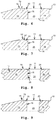
- contraction zone or transition surface 20 is a/o present below, i.e. radially inward of both openings 23 between the respective carrying surfaces 16 and the front surface 11 of the transverse segment 10, as schematically indicated in figure 6 .
- the known design of the transverse segment 10 is schematically reproduced by way of a cross-section of a part thereof including the rocking edge 18, one of the carrying surfaces 16 of the transverse segment 10 and the transition surface 20 between such carrying surface 16 and the front surface 11 of the transverse segment 10.
- the convex curvature of the rocking edge 18 has been exaggerated to be able to discern the convex shape thereof on the scale of this figure.
- the size of the contraction zone 20 has been exaggerated for such purpose in the figures.
- the local transverse segment 20 thickness is less than in-between these two transition surfaces 20, i.e. in line with but below the middle portion 14. It is normal design practice to locate the rocking edge 18 outside these two transition surfaces 20, such that a top side "TS" of the rocking edge 18 is separated by some distance "A" there from, which distance "A", however, is preferably chosen as small as can be reliably produced in order to optimise the efficiency of the pushbelt 6 during operation.
- the top side "TS" of the rocking edge 18 is typically located at around 1 mm below the carrying surfaces 16 of the transverse segment 10, as a result whereof the rocking edge 18 is surely located outside, i.e. radially inward of the transition surfaces 20.
- the above-mentioned distance/radial separation value of 1 mm is intended as an example only. In practice such radial separation can depends on several process parameters such as the thickness of the basic material 50, material properties thereof and even the setup of the blanking device and blanking process as such.
- the thus formed transverse segment 10 is normally subjected to a deburring process such as stone tumbling, as a result whereof edges of the transverse segment 10 between the said main body surfaces 11, 12 and the circumference surface thereof, i.e. including the said acute angle between the transition surface 20 and the carrying surface 16, are rounded-off to a certain extent.
- the said acute angle will thus be replaced by a relatively sharp convex curvature that will normally remain inside an (virtual) arc of radius 0.4 mm or less, typically of around 0.2-0.3 mm.
- rocking edge 18 has been formed as well for the sake of illustration. Still the rocking edge 18 may in principle also be formed independently from the further one process step.
- the top side "TS" of the rocking edge 18 is positioned favourably close(-er) to the carrying surfaces 16, while still being located outside, i.e. below the transition surfaces 20 between these carrying surfaces 16 and the front main surface 11 of the transverse segment 10.
- Figure 10 provides an overhead view of a strip 52 of the basic material 50, wherein the above-mentioned holes 24 are already formed by means of the known blanking process illustrated in the figures 4 and 5 hereof, i.e. wherein the said one process step is already completed.
- the contour of the transverse segment 10 that will be formed, i.e. cut, only in a later stage of the presently described, preferred embodiment of the novel manufacturing method is indicated by the dashed lines.
- a thin layer 25 of the basic material 50 is left both along the bottom side and top side thereof relative to the size and shape of the opening 23 of the transverse segment 10 to be formed later, i.e.
- the said further one process step of cutting out the final shape of the opening 23 of the transverse segment 10 is schematically illustrated.
- the said openings 23 of the transverse segment 10 are finally formed by moving a punch 30 and an ejector 40 of a blanking device, where between the transverse segment 10 (as show in part in figure 12 by its body part 13 and head part 15) to be formed is held, towards a die 80 of the blanking device.
- the die 80 is shaped, in part, in accordance with the openings 23 of the transverse segment 10, such that -by the said movement of the punch 20 and the ejector 30- it scrapes or slices off the said layers 25 of the basic material 50 that were left on both sides of the hole 24 relative to such opening 23.
- the said piece 53 of the basic material 50 which piece 53 was (re-) inserted in the hole 24, supports the yet uncut, i.e. unsliced, parts of the said layers 25 of the basic material 50 and thus reduces a deformation of the basic material 50 in front of the die 80 in response to the cutting forces exerted thereby.
- the rest of the contour of the transverse segment 10 is formed, i.e. is cut from, the strip 52 of the basic material 50.
Landscapes
- Engineering & Computer Science (AREA)
- Mechanical Engineering (AREA)
- General Engineering & Computer Science (AREA)
- Punching Or Piercing (AREA)
Applications Claiming Priority (2)
| Application Number | Priority Date | Filing Date | Title |
|---|---|---|---|
| NL1040477A NL1040477C2 (en) | 2013-11-01 | 2013-11-01 | Method for manufacturing a transverse segment for a pushbelt for a continuously variable transmission and a transverse segment thus obtained. |
| PCT/EP2014/073192 WO2015063132A1 (en) | 2013-11-01 | 2014-10-29 | Method for manufacturing a transverse segment for a pushbelt for a continuously variable transmission and a transverse segment thus obtained |
Publications (2)
| Publication Number | Publication Date |
|---|---|
| EP3063432A1 EP3063432A1 (en) | 2016-09-07 |
| EP3063432B1 true EP3063432B1 (en) | 2018-07-11 |
Family
ID=50114468
Family Applications (1)
| Application Number | Title | Priority Date | Filing Date |
|---|---|---|---|
| EP14798725.9A Not-in-force EP3063432B1 (en) | 2013-11-01 | 2014-10-29 | Method for manufacturing a transverse segment for a pushbelt for a continuously variable transmission and a transverse segment thus obtained |
Country Status (6)
| Country | Link |
|---|---|
| EP (1) | EP3063432B1 (enExample) |
| JP (1) | JP6566943B2 (enExample) |
| CN (1) | CN105683619B (enExample) |
| MX (1) | MX2016005485A (enExample) |
| NL (1) | NL1040477C2 (enExample) |
| WO (1) | WO2015063132A1 (enExample) |
Cited By (1)
| Publication number | Priority date | Publication date | Assignee | Title |
|---|---|---|---|---|
| WO2021098934A1 (en) | 2019-11-22 | 2021-05-27 | Robert Bosch Gmbh | Method for manufacturing a transverse segment for a pushbelt for a continuously variable transmission and a transverse segment thus obtained |
Families Citing this family (7)
| Publication number | Priority date | Publication date | Assignee | Title |
|---|---|---|---|---|
| DE112017000181T5 (de) | 2016-02-12 | 2018-07-19 | Aisin Aw Co., Ltd. | Übertragungsriemen |
| US11047451B2 (en) | 2016-05-18 | 2021-06-29 | Aisin Aw Co., Ltd. | Transmission belt |
| NL1042192B1 (en) * | 2016-12-22 | 2018-06-29 | Bosch Gmbh Robert | A drive belt for a continuously variable transmission with transverse segments and a ring stack and its manufacutring method |
| NL1042198B1 (en) * | 2016-12-27 | 2018-07-03 | Bosch Gmbh Robert | A drive belt for a continuously variable transmission with transverse segments and a ring stack |
| NL1042210B1 (en) * | 2016-12-30 | 2018-07-23 | Bosch Gmbh Robert | Method for manufacturing a transverse segment for a drive belt for a continuously variable transmission |
| NL1043486B1 (en) | 2019-11-28 | 2021-08-31 | Bosch Gmbh Robert | A transverse segment for a drive belt and a continuously variable transmission with a drive belt including the transverse segment |
| NL1043501B1 (en) | 2019-12-10 | 2021-08-31 | Bosch Gmbh Robert | A transverse segment for a drive belt and a drive belt for a continuously variable transmission including the transverse segment and a ring stack |
Family Cites Families (10)
| Publication number | Priority date | Publication date | Assignee | Title |
|---|---|---|---|---|
| JPS5979653U (ja) * | 1982-11-19 | 1984-05-29 | トヨタ自動車株式会社 | 無段変速機用駆動ベルトの押え駒 |
| JP4229532B2 (ja) * | 1999-07-05 | 2009-02-25 | 本田技研工業株式会社 | 無段変速機用ベルト |
| JP2006043719A (ja) * | 2004-08-02 | 2006-02-16 | Toyota Motor Corp | 無段変速機用エレメントおよびその製造方法 |
| JP4879596B2 (ja) * | 2005-02-15 | 2012-02-22 | 日本精工株式会社 | 通孔を有する金属製部材の製造方法 |
| JP2006263768A (ja) * | 2005-02-28 | 2006-10-05 | Aisin Aw Co Ltd | プレス加工装置、及びプレス加工方法 |
| JP2008223956A (ja) * | 2007-03-14 | 2008-09-25 | Toyota Central R&D Labs Inc | 動力伝達用ベルト及びベルト式無段変速機 |
| JP4424376B2 (ja) * | 2007-06-06 | 2010-03-03 | トヨタ自動車株式会社 | 伝動ベルト |
| NL1036318C2 (en) * | 2008-12-16 | 2010-06-17 | Bosch Gmbh Robert | Method for forming defined contact zones on a surface of an element which is destined to be part of a push belt for a continuously variable transmission. |
| NL1039275C2 (en) * | 2011-12-30 | 2013-07-03 | Bosch Gmbh Robert | Method for manufacturing a transverse element which is destined to be part of a drive belt for a continuously variable transmission. |
| CN102699163A (zh) * | 2012-05-29 | 2012-10-03 | 无锡金羊管件有限公司 | 内撑法弯管工艺及专用内撑囊 |
-
2013
- 2013-11-01 NL NL1040477A patent/NL1040477C2/en not_active IP Right Cessation
-
2014
- 2014-10-29 WO PCT/EP2014/073192 patent/WO2015063132A1/en not_active Ceased
- 2014-10-29 MX MX2016005485A patent/MX2016005485A/es unknown
- 2014-10-29 JP JP2016527273A patent/JP6566943B2/ja active Active
- 2014-10-29 EP EP14798725.9A patent/EP3063432B1/en not_active Not-in-force
- 2014-10-29 CN CN201480059209.3A patent/CN105683619B/zh active Active
Non-Patent Citations (1)
| Title |
|---|
| None * |
Cited By (1)
| Publication number | Priority date | Publication date | Assignee | Title |
|---|---|---|---|---|
| WO2021098934A1 (en) | 2019-11-22 | 2021-05-27 | Robert Bosch Gmbh | Method for manufacturing a transverse segment for a pushbelt for a continuously variable transmission and a transverse segment thus obtained |
Also Published As
| Publication number | Publication date |
|---|---|
| EP3063432A1 (en) | 2016-09-07 |
| CN105683619A8 (zh) | 2016-08-03 |
| CN105683619B (zh) | 2018-06-05 |
| MX2016005485A (es) | 2016-08-03 |
| CN105683619A (zh) | 2016-06-15 |
| WO2015063132A1 (en) | 2015-05-07 |
| JP2016537570A (ja) | 2016-12-01 |
| NL1040477C2 (en) | 2015-05-04 |
| JP6566943B2 (ja) | 2019-08-28 |
Similar Documents
| Publication | Publication Date | Title |
|---|---|---|
| EP3063432B1 (en) | Method for manufacturing a transverse segment for a pushbelt for a continuously variable transmission and a transverse segment thus obtained | |
| JP6602768B2 (ja) | ファインブランキング装置 | |
| EP1968760B1 (en) | Method for manufacturing a transverse element that is destined to be part of a push belt for a continuously variable transmission | |
| CN104094017B (zh) | 制造被设为无级变速器的传动带的一部分的横向元件的方法 | |
| NL1041120B1 (en) | An endless metal band with a coated surface, a drive belt provided with the endless metal band and method for shaping the drive belt. | |
| CN102245328B (zh) | 形成用于推送带的横向元件的方法 | |
| JP2007516084A (ja) | 精密打抜装置 | |
| EP1699579B1 (en) | Divided mould having at least two mould components | |
| WO2015101659A1 (en) | Basic material for a transverse segment for a drive belt for a continuously variable transmission and blanking method using it | |
| CN108266494B (zh) | 无级变速器的传动带的横向段的制造方法及制造的横向段 | |
| JP5401472B2 (ja) | 無段変速機用のプッシュベルトに用いられる横断素子を打ち抜くためのブランキングアセンブリ | |
| CN102483128B (zh) | 制造预定成为无级变速器的推送带的一部分的横向元件的方法 | |
| EP2659161B1 (en) | A transverse element for a drive belt and the drive belt | |
| NL1039972C2 (en) | Transverse segment for a pushbelt for a continuously variable transmission and method for blanking it. | |
| JP2018111132A (ja) | 無段変速機に用いられる駆動ベルトのための横断部材の製造方法 | |
| JP2015504007A (ja) | 連続可変トランスミッションの駆動ベルトに使用される横断エレメントを打ち抜くための分割型ブランキング部材 |
Legal Events
| Date | Code | Title | Description |
|---|---|---|---|
| PUAI | Public reference made under article 153(3) epc to a published international application that has entered the european phase |
Free format text: ORIGINAL CODE: 0009012 |
|
| 17P | Request for examination filed |
Effective date: 20160601 |
|
| AK | Designated contracting states |
Kind code of ref document: A1 Designated state(s): AL AT BE BG CH CY CZ DE DK EE ES FI FR GB GR HR HU IE IS IT LI LT LU LV MC MK MT NL NO PL PT RO RS SE SI SK SM TR |
|
| AX | Request for extension of the european patent |
Extension state: BA ME |
|
| DAX | Request for extension of the european patent (deleted) | ||
| STAA | Information on the status of an ep patent application or granted ep patent |
Free format text: STATUS: REQUEST FOR EXAMINATION WAS MADE |
|
| GRAP | Despatch of communication of intention to grant a patent |
Free format text: ORIGINAL CODE: EPIDOSNIGR1 |
|
| STAA | Information on the status of an ep patent application or granted ep patent |
Free format text: STATUS: GRANT OF PATENT IS INTENDED |
|
| INTG | Intention to grant announced |
Effective date: 20180201 |
|
| GRAS | Grant fee paid |
Free format text: ORIGINAL CODE: EPIDOSNIGR3 |
|
| GRAA | (expected) grant |
Free format text: ORIGINAL CODE: 0009210 |
|
| STAA | Information on the status of an ep patent application or granted ep patent |
Free format text: STATUS: THE PATENT HAS BEEN GRANTED |
|
| AK | Designated contracting states |
Kind code of ref document: B1 Designated state(s): AL AT BE BG CH CY CZ DE DK EE ES FI FR GB GR HR HU IE IS IT LI LT LU LV MC MK MT NL NO PL PT RO RS SE SI SK SM TR |
|
| REG | Reference to a national code |
Ref country code: GB Ref legal event code: FG4D |
|
| REG | Reference to a national code |
Ref country code: CH Ref legal event code: EP |
|
| REG | Reference to a national code |
Ref country code: AT Ref legal event code: REF Ref document number: 1017211 Country of ref document: AT Kind code of ref document: T Effective date: 20180715 |
|
| REG | Reference to a national code |
Ref country code: IE Ref legal event code: FG4D |
|
| REG | Reference to a national code |
Ref country code: DE Ref legal event code: R096 Ref document number: 602014028405 Country of ref document: DE |
|
| REG | Reference to a national code |
Ref country code: NL Ref legal event code: FP |
|
| REG | Reference to a national code |
Ref country code: LT Ref legal event code: MG4D |
|
| REG | Reference to a national code |
Ref country code: AT Ref legal event code: MK05 Ref document number: 1017211 Country of ref document: AT Kind code of ref document: T Effective date: 20180711 |
|
| PG25 | Lapsed in a contracting state [announced via postgrant information from national office to epo] |
Ref country code: FI Free format text: LAPSE BECAUSE OF FAILURE TO SUBMIT A TRANSLATION OF THE DESCRIPTION OR TO PAY THE FEE WITHIN THE PRESCRIBED TIME-LIMIT Effective date: 20180711 Ref country code: RS Free format text: LAPSE BECAUSE OF FAILURE TO SUBMIT A TRANSLATION OF THE DESCRIPTION OR TO PAY THE FEE WITHIN THE PRESCRIBED TIME-LIMIT Effective date: 20180711 Ref country code: AT Free format text: LAPSE BECAUSE OF FAILURE TO SUBMIT A TRANSLATION OF THE DESCRIPTION OR TO PAY THE FEE WITHIN THE PRESCRIBED TIME-LIMIT Effective date: 20180711 Ref country code: NO Free format text: LAPSE BECAUSE OF FAILURE TO SUBMIT A TRANSLATION OF THE DESCRIPTION OR TO PAY THE FEE WITHIN THE PRESCRIBED TIME-LIMIT Effective date: 20181011 Ref country code: IS Free format text: LAPSE BECAUSE OF FAILURE TO SUBMIT A TRANSLATION OF THE DESCRIPTION OR TO PAY THE FEE WITHIN THE PRESCRIBED TIME-LIMIT Effective date: 20181111 Ref country code: GR Free format text: LAPSE BECAUSE OF FAILURE TO SUBMIT A TRANSLATION OF THE DESCRIPTION OR TO PAY THE FEE WITHIN THE PRESCRIBED TIME-LIMIT Effective date: 20181012 Ref country code: BG Free format text: LAPSE BECAUSE OF FAILURE TO SUBMIT A TRANSLATION OF THE DESCRIPTION OR TO PAY THE FEE WITHIN THE PRESCRIBED TIME-LIMIT Effective date: 20181011 Ref country code: SE Free format text: LAPSE BECAUSE OF FAILURE TO SUBMIT A TRANSLATION OF THE DESCRIPTION OR TO PAY THE FEE WITHIN THE PRESCRIBED TIME-LIMIT Effective date: 20180711 Ref country code: LT Free format text: LAPSE BECAUSE OF FAILURE TO SUBMIT A TRANSLATION OF THE DESCRIPTION OR TO PAY THE FEE WITHIN THE PRESCRIBED TIME-LIMIT Effective date: 20180711 Ref country code: PL Free format text: LAPSE BECAUSE OF FAILURE TO SUBMIT A TRANSLATION OF THE DESCRIPTION OR TO PAY THE FEE WITHIN THE PRESCRIBED TIME-LIMIT Effective date: 20180711 |
|
| PG25 | Lapsed in a contracting state [announced via postgrant information from national office to epo] |
Ref country code: HR Free format text: LAPSE BECAUSE OF FAILURE TO SUBMIT A TRANSLATION OF THE DESCRIPTION OR TO PAY THE FEE WITHIN THE PRESCRIBED TIME-LIMIT Effective date: 20180711 Ref country code: LV Free format text: LAPSE BECAUSE OF FAILURE TO SUBMIT A TRANSLATION OF THE DESCRIPTION OR TO PAY THE FEE WITHIN THE PRESCRIBED TIME-LIMIT Effective date: 20180711 Ref country code: AL Free format text: LAPSE BECAUSE OF FAILURE TO SUBMIT A TRANSLATION OF THE DESCRIPTION OR TO PAY THE FEE WITHIN THE PRESCRIBED TIME-LIMIT Effective date: 20180711 |
|
| REG | Reference to a national code |
Ref country code: DE Ref legal event code: R097 Ref document number: 602014028405 Country of ref document: DE |
|
| PG25 | Lapsed in a contracting state [announced via postgrant information from national office to epo] |
Ref country code: ES Free format text: LAPSE BECAUSE OF FAILURE TO SUBMIT A TRANSLATION OF THE DESCRIPTION OR TO PAY THE FEE WITHIN THE PRESCRIBED TIME-LIMIT Effective date: 20180711 Ref country code: CZ Free format text: LAPSE BECAUSE OF FAILURE TO SUBMIT A TRANSLATION OF THE DESCRIPTION OR TO PAY THE FEE WITHIN THE PRESCRIBED TIME-LIMIT Effective date: 20180711 Ref country code: RO Free format text: LAPSE BECAUSE OF FAILURE TO SUBMIT A TRANSLATION OF THE DESCRIPTION OR TO PAY THE FEE WITHIN THE PRESCRIBED TIME-LIMIT Effective date: 20180711 Ref country code: IT Free format text: LAPSE BECAUSE OF FAILURE TO SUBMIT A TRANSLATION OF THE DESCRIPTION OR TO PAY THE FEE WITHIN THE PRESCRIBED TIME-LIMIT Effective date: 20180711 Ref country code: EE Free format text: LAPSE BECAUSE OF FAILURE TO SUBMIT A TRANSLATION OF THE DESCRIPTION OR TO PAY THE FEE WITHIN THE PRESCRIBED TIME-LIMIT Effective date: 20180711 |
|
| PLBE | No opposition filed within time limit |
Free format text: ORIGINAL CODE: 0009261 |
|
| STAA | Information on the status of an ep patent application or granted ep patent |
Free format text: STATUS: NO OPPOSITION FILED WITHIN TIME LIMIT |
|
| PG25 | Lapsed in a contracting state [announced via postgrant information from national office to epo] |
Ref country code: DK Free format text: LAPSE BECAUSE OF FAILURE TO SUBMIT A TRANSLATION OF THE DESCRIPTION OR TO PAY THE FEE WITHIN THE PRESCRIBED TIME-LIMIT Effective date: 20180711 Ref country code: SM Free format text: LAPSE BECAUSE OF FAILURE TO SUBMIT A TRANSLATION OF THE DESCRIPTION OR TO PAY THE FEE WITHIN THE PRESCRIBED TIME-LIMIT Effective date: 20180711 Ref country code: SK Free format text: LAPSE BECAUSE OF FAILURE TO SUBMIT A TRANSLATION OF THE DESCRIPTION OR TO PAY THE FEE WITHIN THE PRESCRIBED TIME-LIMIT Effective date: 20180711 |
|
| REG | Reference to a national code |
Ref country code: CH Ref legal event code: PL |
|
| 26N | No opposition filed |
Effective date: 20190412 |
|
| GBPC | Gb: european patent ceased through non-payment of renewal fee |
Effective date: 20181029 |
|
| REG | Reference to a national code |
Ref country code: BE Ref legal event code: MM Effective date: 20181031 |
|
| PG25 | Lapsed in a contracting state [announced via postgrant information from national office to epo] |
Ref country code: MC Free format text: LAPSE BECAUSE OF FAILURE TO SUBMIT A TRANSLATION OF THE DESCRIPTION OR TO PAY THE FEE WITHIN THE PRESCRIBED TIME-LIMIT Effective date: 20180711 Ref country code: LU Free format text: LAPSE BECAUSE OF NON-PAYMENT OF DUE FEES Effective date: 20181029 |
|
| REG | Reference to a national code |
Ref country code: IE Ref legal event code: MM4A |
|
| PG25 | Lapsed in a contracting state [announced via postgrant information from national office to epo] |
Ref country code: BE Free format text: LAPSE BECAUSE OF NON-PAYMENT OF DUE FEES Effective date: 20181031 Ref country code: FR Free format text: LAPSE BECAUSE OF NON-PAYMENT OF DUE FEES Effective date: 20181031 Ref country code: CH Free format text: LAPSE BECAUSE OF NON-PAYMENT OF DUE FEES Effective date: 20181031 Ref country code: LI Free format text: LAPSE BECAUSE OF NON-PAYMENT OF DUE FEES Effective date: 20181031 Ref country code: SI Free format text: LAPSE BECAUSE OF FAILURE TO SUBMIT A TRANSLATION OF THE DESCRIPTION OR TO PAY THE FEE WITHIN THE PRESCRIBED TIME-LIMIT Effective date: 20180711 |
|
| PG25 | Lapsed in a contracting state [announced via postgrant information from national office to epo] |
Ref country code: IE Free format text: LAPSE BECAUSE OF NON-PAYMENT OF DUE FEES Effective date: 20181029 Ref country code: GB Free format text: LAPSE BECAUSE OF NON-PAYMENT OF DUE FEES Effective date: 20181029 |
|
| PG25 | Lapsed in a contracting state [announced via postgrant information from national office to epo] |
Ref country code: MT Free format text: LAPSE BECAUSE OF NON-PAYMENT OF DUE FEES Effective date: 20181029 |
|
| PG25 | Lapsed in a contracting state [announced via postgrant information from national office to epo] |
Ref country code: TR Free format text: LAPSE BECAUSE OF FAILURE TO SUBMIT A TRANSLATION OF THE DESCRIPTION OR TO PAY THE FEE WITHIN THE PRESCRIBED TIME-LIMIT Effective date: 20180711 |
|
| PG25 | Lapsed in a contracting state [announced via postgrant information from national office to epo] |
Ref country code: PT Free format text: LAPSE BECAUSE OF FAILURE TO SUBMIT A TRANSLATION OF THE DESCRIPTION OR TO PAY THE FEE WITHIN THE PRESCRIBED TIME-LIMIT Effective date: 20180711 |
|
| PG25 | Lapsed in a contracting state [announced via postgrant information from national office to epo] |
Ref country code: MK Free format text: LAPSE BECAUSE OF NON-PAYMENT OF DUE FEES Effective date: 20180711 Ref country code: HU Free format text: LAPSE BECAUSE OF FAILURE TO SUBMIT A TRANSLATION OF THE DESCRIPTION OR TO PAY THE FEE WITHIN THE PRESCRIBED TIME-LIMIT; INVALID AB INITIO Effective date: 20141029 Ref country code: CY Free format text: LAPSE BECAUSE OF FAILURE TO SUBMIT A TRANSLATION OF THE DESCRIPTION OR TO PAY THE FEE WITHIN THE PRESCRIBED TIME-LIMIT Effective date: 20180711 |
|
| PGFP | Annual fee paid to national office [announced via postgrant information from national office to epo] |
Ref country code: NL Payment date: 20221021 Year of fee payment: 9 |
|
| PGFP | Annual fee paid to national office [announced via postgrant information from national office to epo] |
Ref country code: DE Payment date: 20221215 Year of fee payment: 9 |
|
| REG | Reference to a national code |
Ref country code: DE Ref legal event code: R119 Ref document number: 602014028405 Country of ref document: DE |
|
| REG | Reference to a national code |
Ref country code: NL Ref legal event code: MM Effective date: 20231101 |
|
| PG25 | Lapsed in a contracting state [announced via postgrant information from national office to epo] |
Ref country code: NL Free format text: LAPSE BECAUSE OF NON-PAYMENT OF DUE FEES Effective date: 20231101 |
|
| PG25 | Lapsed in a contracting state [announced via postgrant information from national office to epo] |
Ref country code: NL Free format text: LAPSE BECAUSE OF NON-PAYMENT OF DUE FEES Effective date: 20231101 Ref country code: DE Free format text: LAPSE BECAUSE OF NON-PAYMENT OF DUE FEES Effective date: 20240501 |