EP3062396A1 - Prise de courant pour habitacle de véhicule - Google Patents
Prise de courant pour habitacle de véhicule Download PDFInfo
- Publication number
- EP3062396A1 EP3062396A1 EP16156787.0A EP16156787A EP3062396A1 EP 3062396 A1 EP3062396 A1 EP 3062396A1 EP 16156787 A EP16156787 A EP 16156787A EP 3062396 A1 EP3062396 A1 EP 3062396A1
- Authority
- EP
- European Patent Office
- Prior art keywords
- socket
- electrical connection
- connection element
- clinching
- base
- Prior art date
- Legal status (The legal status is an assumption and is not a legal conclusion. Google has not performed a legal analysis and makes no representation as to the accuracy of the status listed.)
- Withdrawn
Links
- 238000004519 manufacturing process Methods 0.000 claims description 14
- 208000031968 Cadaver Diseases 0.000 description 27
- 210000002105 tongue Anatomy 0.000 description 18
- 238000000034 method Methods 0.000 description 4
- 239000000463 material Substances 0.000 description 3
- RYGMFSIKBFXOCR-UHFFFAOYSA-N Copper Chemical compound [Cu] RYGMFSIKBFXOCR-UHFFFAOYSA-N 0.000 description 2
- XAGFODPZIPBFFR-UHFFFAOYSA-N aluminium Chemical compound [Al] XAGFODPZIPBFFR-UHFFFAOYSA-N 0.000 description 2
- 229910052782 aluminium Inorganic materials 0.000 description 2
- 239000004020 conductor Substances 0.000 description 2
- VYZAMTAEIAYCRO-UHFFFAOYSA-N Chromium Chemical compound [Cr] VYZAMTAEIAYCRO-UHFFFAOYSA-N 0.000 description 1
- 239000004411 aluminium Substances 0.000 description 1
- 239000010949 copper Substances 0.000 description 1
- 229910052802 copper Inorganic materials 0.000 description 1
- 238000005520 cutting process Methods 0.000 description 1
- 238000003780 insertion Methods 0.000 description 1
- 230000037431 insertion Effects 0.000 description 1
- 239000011159 matrix material Substances 0.000 description 1
- 238000003825 pressing Methods 0.000 description 1
- 238000004080 punching Methods 0.000 description 1
- 230000000717 retained effect Effects 0.000 description 1
Images


Classifications
-
- H—ELECTRICITY
- H01—ELECTRIC ELEMENTS
- H01R—ELECTRICALLY-CONDUCTIVE CONNECTIONS; STRUCTURAL ASSOCIATIONS OF A PLURALITY OF MUTUALLY-INSULATED ELECTRICAL CONNECTING ELEMENTS; COUPLING DEVICES; CURRENT COLLECTORS
- H01R24/00—Two-part coupling devices, or either of their cooperating parts, characterised by their overall structure
- H01R24/66—Two-part coupling devices, or either of their cooperating parts, characterised by their overall structure with pins, blades or analogous contacts and secured to apparatus or structure, e.g. to a wall
- H01R24/70—Two-part coupling devices, or either of their cooperating parts, characterised by their overall structure with pins, blades or analogous contacts and secured to apparatus or structure, e.g. to a wall with additional earth or shield contacts
-
- B—PERFORMING OPERATIONS; TRANSPORTING
- B60—VEHICLES IN GENERAL
- B60N—SEATS SPECIALLY ADAPTED FOR VEHICLES; VEHICLE PASSENGER ACCOMMODATION NOT OTHERWISE PROVIDED FOR
- B60N3/00—Arrangements or adaptations of other passenger fittings, not otherwise provided for
- B60N3/14—Arrangements or adaptations of other passenger fittings, not otherwise provided for of electrically-heated lighters
-
- H—ELECTRICITY
- H01—ELECTRIC ELEMENTS
- H01R—ELECTRICALLY-CONDUCTIVE CONNECTIONS; STRUCTURAL ASSOCIATIONS OF A PLURALITY OF MUTUALLY-INSULATED ELECTRICAL CONNECTING ELEMENTS; COUPLING DEVICES; CURRENT COLLECTORS
- H01R13/00—Details of coupling devices of the kinds covered by groups H01R12/70 or H01R24/00 - H01R33/00
- H01R13/40—Securing contact members in or to a base or case; Insulating of contact members
- H01R13/405—Securing in non-demountable manner, e.g. moulding, riveting
-
- H—ELECTRICITY
- H01—ELECTRIC ELEMENTS
- H01R—ELECTRICALLY-CONDUCTIVE CONNECTIONS; STRUCTURAL ASSOCIATIONS OF A PLURALITY OF MUTUALLY-INSULATED ELECTRICAL CONNECTING ELEMENTS; COUPLING DEVICES; CURRENT COLLECTORS
- H01R13/00—Details of coupling devices of the kinds covered by groups H01R12/70 or H01R24/00 - H01R33/00
- H01R13/02—Contact members
-
- H—ELECTRICITY
- H01—ELECTRIC ELEMENTS
- H01R—ELECTRICALLY-CONDUCTIVE CONNECTIONS; STRUCTURAL ASSOCIATIONS OF A PLURALITY OF MUTUALLY-INSULATED ELECTRICAL CONNECTING ELEMENTS; COUPLING DEVICES; CURRENT COLLECTORS
- H01R13/00—Details of coupling devices of the kinds covered by groups H01R12/70 or H01R24/00 - H01R33/00
- H01R13/46—Bases; Cases
- H01R13/502—Bases; Cases composed of different pieces
-
- H—ELECTRICITY
- H01—ELECTRIC ELEMENTS
- H01R—ELECTRICALLY-CONDUCTIVE CONNECTIONS; STRUCTURAL ASSOCIATIONS OF A PLURALITY OF MUTUALLY-INSULATED ELECTRICAL CONNECTING ELEMENTS; COUPLING DEVICES; CURRENT COLLECTORS
- H01R27/00—Coupling parts adapted for co-operation with two or more dissimilar counterparts
-
- H—ELECTRICITY
- H01—ELECTRIC ELEMENTS
- H01R—ELECTRICALLY-CONDUCTIVE CONNECTIONS; STRUCTURAL ASSOCIATIONS OF A PLURALITY OF MUTUALLY-INSULATED ELECTRICAL CONNECTING ELEMENTS; COUPLING DEVICES; CURRENT COLLECTORS
- H01R4/00—Electrically-conductive connections between two or more conductive members in direct contact, i.e. touching one another; Means for effecting or maintaining such contact; Electrically-conductive connections having two or more spaced connecting locations for conductors and using contact members penetrating insulation
- H01R4/06—Riveted connections
-
- H—ELECTRICITY
- H01—ELECTRIC ELEMENTS
- H01R—ELECTRICALLY-CONDUCTIVE CONNECTIONS; STRUCTURAL ASSOCIATIONS OF A PLURALITY OF MUTUALLY-INSULATED ELECTRICAL CONNECTING ELEMENTS; COUPLING DEVICES; CURRENT COLLECTORS
- H01R4/00—Electrically-conductive connections between two or more conductive members in direct contact, i.e. touching one another; Means for effecting or maintaining such contact; Electrically-conductive connections having two or more spaced connecting locations for conductors and using contact members penetrating insulation
- H01R4/10—Electrically-conductive connections between two or more conductive members in direct contact, i.e. touching one another; Means for effecting or maintaining such contact; Electrically-conductive connections having two or more spaced connecting locations for conductors and using contact members penetrating insulation effected solely by twisting, wrapping, bending, crimping, or other permanent deformation
- H01R4/18—Electrically-conductive connections between two or more conductive members in direct contact, i.e. touching one another; Means for effecting or maintaining such contact; Electrically-conductive connections having two or more spaced connecting locations for conductors and using contact members penetrating insulation effected solely by twisting, wrapping, bending, crimping, or other permanent deformation by crimping
-
- H—ELECTRICITY
- H01—ELECTRIC ELEMENTS
- H01R—ELECTRICALLY-CONDUCTIVE CONNECTIONS; STRUCTURAL ASSOCIATIONS OF A PLURALITY OF MUTUALLY-INSULATED ELECTRICAL CONNECTING ELEMENTS; COUPLING DEVICES; CURRENT COLLECTORS
- H01R4/00—Electrically-conductive connections between two or more conductive members in direct contact, i.e. touching one another; Means for effecting or maintaining such contact; Electrically-conductive connections having two or more spaced connecting locations for conductors and using contact members penetrating insulation
- H01R4/10—Electrically-conductive connections between two or more conductive members in direct contact, i.e. touching one another; Means for effecting or maintaining such contact; Electrically-conductive connections having two or more spaced connecting locations for conductors and using contact members penetrating insulation effected solely by twisting, wrapping, bending, crimping, or other permanent deformation
- H01R4/18—Electrically-conductive connections between two or more conductive members in direct contact, i.e. touching one another; Means for effecting or maintaining such contact; Electrically-conductive connections having two or more spaced connecting locations for conductors and using contact members penetrating insulation effected solely by twisting, wrapping, bending, crimping, or other permanent deformation by crimping
- H01R4/188—Electrically-conductive connections between two or more conductive members in direct contact, i.e. touching one another; Means for effecting or maintaining such contact; Electrically-conductive connections having two or more spaced connecting locations for conductors and using contact members penetrating insulation effected solely by twisting, wrapping, bending, crimping, or other permanent deformation by crimping having an uneven wire-receiving surface to improve the contact
-
- H—ELECTRICITY
- H01—ELECTRIC ELEMENTS
- H01R—ELECTRICALLY-CONDUCTIVE CONNECTIONS; STRUCTURAL ASSOCIATIONS OF A PLURALITY OF MUTUALLY-INSULATED ELECTRICAL CONNECTING ELEMENTS; COUPLING DEVICES; CURRENT COLLECTORS
- H01R43/00—Apparatus or processes specially adapted for manufacturing, assembling, maintaining, or repairing of line connectors or current collectors or for joining electric conductors
- H01R43/04—Apparatus or processes specially adapted for manufacturing, assembling, maintaining, or repairing of line connectors or current collectors or for joining electric conductors for forming connections by deformation, e.g. crimping tool
- H01R43/048—Crimping apparatus or processes
-
- H—ELECTRICITY
- H01—ELECTRIC ELEMENTS
- H01R—ELECTRICALLY-CONDUCTIVE CONNECTIONS; STRUCTURAL ASSOCIATIONS OF A PLURALITY OF MUTUALLY-INSULATED ELECTRICAL CONNECTING ELEMENTS; COUPLING DEVICES; CURRENT COLLECTORS
- H01R43/00—Apparatus or processes specially adapted for manufacturing, assembling, maintaining, or repairing of line connectors or current collectors or for joining electric conductors
- H01R43/20—Apparatus or processes specially adapted for manufacturing, assembling, maintaining, or repairing of line connectors or current collectors or for joining electric conductors for assembling or disassembling contact members with insulating base, case or sleeve
-
- H—ELECTRICITY
- H01—ELECTRIC ELEMENTS
- H01R—ELECTRICALLY-CONDUCTIVE CONNECTIONS; STRUCTURAL ASSOCIATIONS OF A PLURALITY OF MUTUALLY-INSULATED ELECTRICAL CONNECTING ELEMENTS; COUPLING DEVICES; CURRENT COLLECTORS
- H01R13/00—Details of coupling devices of the kinds covered by groups H01R12/70 or H01R24/00 - H01R33/00
- H01R13/02—Contact members
- H01R13/20—Pins, blades, or sockets shaped, or provided with separate member, to retain co-operating parts together
-
- H—ELECTRICITY
- H01—ELECTRIC ELEMENTS
- H01R—ELECTRICALLY-CONDUCTIVE CONNECTIONS; STRUCTURAL ASSOCIATIONS OF A PLURALITY OF MUTUALLY-INSULATED ELECTRICAL CONNECTING ELEMENTS; COUPLING DEVICES; CURRENT COLLECTORS
- H01R13/00—Details of coupling devices of the kinds covered by groups H01R12/70 or H01R24/00 - H01R33/00
- H01R13/648—Protective earth or shield arrangements on coupling devices, e.g. anti-static shielding
- H01R13/652—Protective earth or shield arrangements on coupling devices, e.g. anti-static shielding with earth pin, blade or socket
-
- H—ELECTRICITY
- H01—ELECTRIC ELEMENTS
- H01R—ELECTRICALLY-CONDUCTIVE CONNECTIONS; STRUCTURAL ASSOCIATIONS OF A PLURALITY OF MUTUALLY-INSULATED ELECTRICAL CONNECTING ELEMENTS; COUPLING DEVICES; CURRENT COLLECTORS
- H01R13/00—Details of coupling devices of the kinds covered by groups H01R12/70 or H01R24/00 - H01R33/00
- H01R13/73—Means for mounting coupling parts to apparatus or structures, e.g. to a wall
- H01R13/74—Means for mounting coupling parts in openings of a panel
- H01R13/741—Means for mounting coupling parts in openings of a panel using snap fastening means
- H01R13/743—Means for mounting coupling parts in openings of a panel using snap fastening means integral with the housing
-
- H—ELECTRICITY
- H01—ELECTRIC ELEMENTS
- H01R—ELECTRICALLY-CONDUCTIVE CONNECTIONS; STRUCTURAL ASSOCIATIONS OF A PLURALITY OF MUTUALLY-INSULATED ELECTRICAL CONNECTING ELEMENTS; COUPLING DEVICES; CURRENT COLLECTORS
- H01R2103/00—Two poles
-
- H—ELECTRICITY
- H01—ELECTRIC ELEMENTS
- H01R—ELECTRICALLY-CONDUCTIVE CONNECTIONS; STRUCTURAL ASSOCIATIONS OF A PLURALITY OF MUTUALLY-INSULATED ELECTRICAL CONNECTING ELEMENTS; COUPLING DEVICES; CURRENT COLLECTORS
- H01R2201/00—Connectors or connections adapted for particular applications
- H01R2201/26—Connectors or connections adapted for particular applications for vehicles
-
- H—ELECTRICITY
- H01—ELECTRIC ELEMENTS
- H01R—ELECTRICALLY-CONDUCTIVE CONNECTIONS; STRUCTURAL ASSOCIATIONS OF A PLURALITY OF MUTUALLY-INSULATED ELECTRICAL CONNECTING ELEMENTS; COUPLING DEVICES; CURRENT COLLECTORS
- H01R24/00—Two-part coupling devices, or either of their cooperating parts, characterised by their overall structure
- H01R24/58—Contacts spaced along longitudinal axis of engagement
Definitions
- the invention relates to power outlets for vehicle cabin.
- This socket located at or below the dashboard of the vehicle, comprises four components: a cover, a socket body comprising a so-called “negative” connection tab, a ring with an integrated connection body and a connection tab electrical called "positive".
- a cover By opening the hood, a user can connect one of his electrical devices.
- the product intended for another car manufacturer includes nine elements, whose elements similar to those of the first grip have different dimensions.
- the product is adapted to the dimensions of the dashboard, the layout of its interior, as well as the design of the manufacturer.
- the number of nine pieces is relatively high, which generates costs including the manufacture of all these parts and the management of their inventory.
- the vehicle's intake body is designed to accommodate only the negative electrical connection tab provided for these vehicles. The same disadvantage is valid for other manufacturers for which the plaintiff provides receptacles for vehicle cabin.
- An object of the invention is to provide a product adaptable to several types of manufacturers.
- the socket body is compatible with several connection elements different electrical, for example so-called negative connection tongues, and it is no longer necessary to design a socket body for each different type of outlet corresponding to different car manufacturers.
- This arrangement also allows as will be seen to manufacture the plug with a relatively small number of parts, for example five.
- the attachment of the electrical connection element attached to the gripping body prevents the addition of material during fixing and ensures a better electrical conductivity between these two parts.
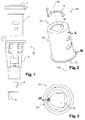
- the figure 1 shows a plug 10 or 12 V type power plug for a habitable vehicle made by means of an assembly according to one embodiment of the invention.
- a socket body 2 which is the only component of this set to be identical in all the outlets we will describe. Also illustrated is a base or ring 3 adapted to receive the body 2, a first electrical connection element 5 that we will call in the negative tab sequence, and a second electrical connection element 4 that we will call in the following positive tab.
- the figure 2 allows to better visualize the body 2 and the negative tongue 5.
- the body has a generally tubular shape at its main portion 22, in this case cylindrical of revolution about an axis 29.
- One of its ends 21 has a circular rim or flange 26.
- This circular flange 26 surrounds at least partially an opening 27 of the socket body 2.
- This opening 27 opens on a receptacle for receiving a connector for the power supply of an electrical appliance.
- the opposite end 23 may have in the center a main opening 24 opening formed of a semicircle contiguous to a rectangle. Alternatively, the opposite end 23 may be full.
- the body has two circumferential rectangular orifices aligned vertically, with one slightly longer than the other.
- the socket body 2 is thus compatible with several negative tabs, but can receive only one at a time.
- the figure 3 it is precisely possible to visualize, in a view from below, the attachment by a double point 28 obtained by clinching, of the negative tab 5 in the end 23 of the body.
- the double point 28 is obtained by stamping the grip body into the negative tab.
- the negative tab 5 comprises a planar support 51 which has substantially a semicircular shape, and a projecting flat portion 54, which forms the connection tab itself.
- the tongue 54 is oriented perpendicular to the support 51.
- the tongue 54 is located in the extension of the semicircle formed by the support 51.
- Regarding the manufacture of this first connection element it is manufactured flat.
- the dotted lines also illustrate the position of the tongue 54 when the element is flat.
- This connecting element is derived from the cutting of a flat sheet, the tongue itself 54 is folded so as to be oriented perpendicularly to the support 51.
- connection elements of the Figures 7 and 8 have the same elements, but have dimensions and / or different positions.
- the tongue 64 is on the center of the semicircular support 61.
- the tongue 64 has a base 65 narrowed with respect to a main portion 66 wider than the tongue 54 of the connection element 5.
- the tab itself 74 is located at the same place as the element 5, that is to say in the extension of the semicircular support 71.
- the tab itself that is to say the flat part 74, has larger dimensions, in length as in width, than the tabs 54 and 64 of the first two connection elements described above.
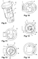
- the figure 9 illustrates a socket made with the elements of the figure 1 .
- the cover 1 which opens the socket 10 to connect a connector, and the socket body 2 which is received and maintained in the base 3.
- the latter comprises a circular portion 31, referenced in particular to the figure 11 , which is identical for the three socket bases described here, although these bases are different to adapt to the three negative tabs and three corresponding positive tabs.
- the figure 12 illustrates a view of the assembly making it possible to distinguish the body 2 retained in the base 3, the attachment points by clinching 52 and 53 of the negative element 5 in the body 2, and in the middle of the base 3, a second element of electrical connection 4 having a positive tab.
- the gripping body 2 and the base 3 sandwich the negative element 5 between their bottoms.
- the fastening points by clinching 52 and 53 are obtained by stamping the support 51 of the negative tab 5 in the plane background 23. of the socket body 2.
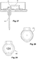
- the arrangement of the second electrical connection element 4 with the positive tab is also visible at the figure 27 . It has a flat portion 41 and the actual tab 42, which extends in the direction perpendicular to the flat portion 41.
- the positive tab has in its center a 43 hexagonal hole, referenced to the figure 12 .
- a relief 32 of the bottom of the base extends projecting from the bottom of the body through its orifice and serves as a stop when connecting a connector to this socket 10. This circular relief 32 surrounds the positive tab 41.
- the negative tab 5 is fixed to the grip body by two fastening points 52 and 53 obtained by clinching.
- This fixing is done by stamping the two parts between a punch, guided by a press, and a matrix.
- the punch can stamp the body 2 in the electrical element 3 or the electrical element 3 in the body 2.
- the removal of the punch leaves a cavity at the point of attachment.
- the parts undergo cold plastic deformation forming a connection point so that the negative tongue can not be removed from the body without damaging the body or tongue.
- This type of fixation corresponds to clinching.
- the type of clinching used is "TOX-micropoint".
- FIG. figure 30 A "TOX-micropoint” type clinching process is illustrated in FIG. figure 30 .
- a negative tab 91 is pressed into a grip body 92. This is shown schematically in the figure 31 . It is also possible to stamp the grip body 92 in the negative tab 91.
- Other types of clinchages are used, such as the "RivetClinch TOX”, schematically shown in FIG. figure 32 .
- the stitch suits are comparable to those of a self-punching rivet, but at a lower cost.
- Another type of clinching is the "TOX-TWINpoint" or double attachment point, shown at figure 33 .
- the double point prevents the rotation of the point and the outfits are about twice higher than those of a single point process. All these types of clinching also offer excellent electrical conductivity and are performed without adding material.
- the figure 13 is an end view similar to that of the figure 12 but without the body and the positive and negative tabs.
- a central location 37 is intended to receive the plane support 41 of the positive tongue 4, while the contours 38 of the base are arranged to maintain the fixed body 2 in the fixed position.
- the base also comprises two rectangular openings 34 and 35. and a central orifice 36. These openings 34 and 35 allow the passage of the tongue of the electrical connection element.
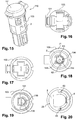
- the Figures 15 to 20 show a second socket, in which the socket body 2 is identical to that of the first embodiment. Similarly, the base 103 comprises a portion 31 identical to that of the first mode.
- this grip is the negative tab 6 which is fixed to the grip body, instead of the negative tab 5.
- the fixing points 62 and 63 of the negative tab 6 are positioned on either side of the negative tab and at the ends of the flat support 61 of the negative tab 6, the flat support 61 having a semicircular shape.
- the fixing points by clinching 62 and 63 are obtained by stamping the support 61 of the negative tab 6 in the plane bottom 23 of the grip body 2.
- the figure 18 illustrates a view from above of the assembly of this second socket, again without cover, which comprises a positive tab 104 different from the tongue 4 by the shape of its support 141, and the fixing points 62 and 63 of the negative tab 6 attached to the body 2.
- the Figures 16, 17 and 19 illustrate base views 103, which differs from the previous base 3. In particular, there is no round central orifice.
- the base 103 on the other hand, has two rectangular openings 135 and 136 visible to the figure 19 , which are this time parallel to each other.
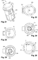
- the figure 21 illustrates a third catch.
- the gripping body 2 is still identical, and this catch has the main peculiarity of comprising the negative tongue 7, which is fixed to the body by the attachment points 72 and 73, as can be seen in FIGS. figures 24 and 26 .
- the fastening points by clinching 72 and 73 are obtained by stamping the plane bottom 23 of the socket body 2 in the support 71 of the negative tab 7.
- the base 203 has the identical part 31, but it is adapted to the tongue negative 7 and the positive tab that is specific to it and its support 241, visible to the figure 24 .
- the rectangular openings 234 and 235 are perpendicular like those of the first grip, but they are longer, as illustrated in FIG. figure 25 , while there is a round central orifice 236 unlike the support of the second socket.
- the plug body 2 is therefore arranged to receive the three types of negative tab elements, but only one at a time.
- Figures 28 and 29 have two types of opening cover possible for different outlets.
- the hood 351 of the figure 28 is classic while the hood 352 of the figure 29 is chrome and has inscriptions (eg "12V").
- the assembly also comprises pedestals 3 adapted to be fixed to the body 2.
- the pedestals are here of three types also which differ from each other but have an identical part 31.
- the assembly further comprises three types of second positive electrical connection elements 4 different from each other.
- a power outlet For the manufacture of a power outlet, it has such an assembly and one of the negative elements 5, 6 or 7 to the body 2. It also adds a positive elements, a base and a cover.
- This set therefore makes it possible to manufacture three different types of outlets and thus makes it possible to obtain a set here comprising three types of different outlets.
- Each jack here includes five coins in total.
- the number of different positive or negative connection elements, the number of pedestals and the number of hoods can be varied overall.
Landscapes
- Engineering & Computer Science (AREA)
- Manufacturing & Machinery (AREA)
- Transportation (AREA)
- Mechanical Engineering (AREA)
- Details Of Connecting Devices For Male And Female Coupling (AREA)
- Connector Housings Or Holding Contact Members (AREA)
Abstract
Description
- L'invention concerne les prises de courant pour habitacle de véhicule.
- Ces prises, dites « 12 Volt », bien qu'elles acceptent aussi les tensions de 24V, permettent de brancher des appareils électriques tels que des GPS, des chauffe-biberons, des convertisseurs ou des chargeurs électriques...
- On connaît à cet effet un produit de la demanderesse. Cette prise, située au niveau ou en dessous du tableau de bord du véhicule, comprend quatre composants : un capot, un corps de prise comprenant une languette de connexion dite « négative », un anneau avec un corps de connexion intégré et une languette de connexion électrique dite « positive ». En ouvrant le capot, un utilisateur peut y brancher l'un de ses appareils électriques.
- L'inconvénient de ce produit est qu'il n'est compatible qu'avec les véhicules fabriqués par un nombre limité de constructeurs automobiles. Ainsi, le corps de prise du produit est conçu pour accueillir uniquement la languette de connexion électrique négative adéquate.
- Parallèlement, le produit destiné à un autre constructeur automobile comprend neuf éléments, dont les éléments similaires à ceux de la première prise présentent des dimensions différentes. Le produit est adapté aux dimensions du tableau de bord, à l'agencement de son intérieur, ainsi qu'au design du constructeur. Le nombre de neuf pièces est relativement élevé, ce qui engendre des coûts notamment pour la fabrication de toutes ces pièces et la gestion de leurs stocks. De même, le corps de prise pour les véhicules de ce constructeur est conçu pour accueillir uniquement la languette de connexion électrique négative prévue pour ces véhicules. Le même inconvénient vaut pour d'autres constructeurs pour lesquels la demanderesse fournit des prises de courant pour habitacle de véhicule.
- La même situation peut se présenter pour d'autres fournisseurs de prises pour véhicule qui doivent donc produire pour les différents constructeurs plusieurs produits différents, bien que les éléments de ces produits soient similaires.
- Un but de l'invention est de proposer un produit adaptable à plusieurs types de constructeurs.
- On prévoit à cet effet un ensemble pour la réalisation d'une prise de courant pour un habitacle de véhicule, l'ensemble comprenant :
- un corps de prise ; et
- au moins un élément de connexion électrique fixé au corps de prise par clinchage.
- Ainsi, le corps de prise est compatible avec plusieurs éléments de connexion électriques différents, par exemple des languettes de connexion dites négatives, et on n'est plus obligé de concevoir un corps de prise pour chaque type de prise différent correspondant à différents constructeurs automobiles. Cet agencement autorise aussi comme on le verra de fabriquer la prise avec un nombre relativement réduit de pièces, par exemple cinq.
- D'autre part, la fixation de l'élément de connexion électrique fixé au corps de prise par clinchage évite l'ajout de matière lors de la fixation et permet d'assurer une meilleure conductivité électrique entre ces deux pièces.
- En outre l'invention possède les caractéristiques suivantes, considérées isolément ou en combinaison :
- la fixation entre le corps de prise et l'élément de connexion électrique est agencée pour permettre un contact électrique entre le corps de prise et l'élément de connexion,
- le corps de prise comprend une ouverture débouchant sur un réceptacle destiné à recevoir un connecteur pour l'alimentation électrique d'un appareil électrique,
- le corps de prise comprend au moins un fond plan opposé à l'ouverture du réceptacle,
- le fond plan du corps de prise comprend au moins un orifice débouchant principal,
- l'orifice débouchant principal est situé au centre du fond plan du corps de prise,
- l'orifice débouchant principal présente un pourtour comprenant au moins un arc de cercle,
- le ou chaque élément de connexion électrique comprend un support plan, et une languette en saillie du support,
- le support plan est fixé au fond plan du corps de prise par clinchage,
- le support plan borde au moins en partie l'orifice débouchant principal,
- la prise de courant comprend un socle fixé dans une position prédéterminée au corps,
- le socle est une bague,
- le socle présente un relief s'étendant en saillie d'un fond du socle pour former une butée dans la prise lors de la réception d'un connecteur,
- l'élément de connexion électrique étant un premier élément de connexion électrique, la prise de courant comprend en outre au moins un deuxième élément de connexion électrique,
- chaque deuxième élément présente un orifice sensiblement hexagonal de connexion électrique,
- le premier élément est fixé au corps par clinchage au niveau d'au moins un point de fixation,
- le premier élément est fixé au corps par deux points de fixation obtenu par clinchage,
- chaque point de fixation est de forme circulaire, conique, rectangulaire, polygonal, ou de forme hybride obtenue à partir des formes précédentes,
- chaque point de fixation est de forme circulaire,
- chaque point de fixation est un point de fixation double,
- la prise de courant comprend au moins un capot de fermeture d'un logement de la prise,
- le corps de prise et chaque élément de connexion électrique sont formés d'au moins un matériau électriquement conducteur,
- le corps de prise le au moins un matériau électriquement conducteur comprend de l'aluminium et/ou du cuivre.
- L'invention a aussi pour objet un procédé de fabrication d'une prise de courant pour habitacle de véhicule comprenant un corps de prise et un élément de connexion électrique, l'élément de connexion électrique étant fixé au corps de prise selon les étapes suivantes :
- mettre en contact l'élément de connexion électrique et le corps de prise,
- fixer l'élément de connexion électrique au corps de prise par clinchage.
- De plus l'invention possède les caractéristiques suivantes, considérées isolément ou en combinaison :
- le premier élément est fixé au corps par au moins un point de fixation obtenu par clinchage,
- le point de fixation obtenu par clinchage est un point double. Avantageusement, cette caractéristique permet d'éviter la rotation de l'élément de connexion électrique,
- le premier élément est fixé au corps par au moins deux points de fixation obtenus en même temps par clinchage. Avantageusement, cette caractéristique permet d'éviter la rotation de l'élément de connexion électrique,
- l'étape de fixation de l'élément de connexion électrique au corps de prise est réalisée sans ajout de matière,
- l'élément de connexion électrique est embouti dans le corps de prise,
- l'emboutissage de l'élément de connexion électrique dans le corps de prise crée au moins un premier renfoncement dans l'élément de connexion et un deuxième renfoncement dans le corps de prise de sorte à ce qu'une partie d'une paroi extérieure du premier renfoncement vienne en saillie dans une paroi intérieure du deuxième renfoncement,
- le corps de prise est embouti dans l'élément de connexion électrique,
- le procédé de fabrication comprend une étape d'insertion du corps de prise dans un socle,
- le procédé de fabrication comprend comprenant une étape de fixation d'un capot sur le socle.
- D'autres caractéristiques et avantages de la présente invention apparaîtront plus clairement à la lecture de la description suivante donnée à titre d'exemple illustratif et non limitatif et faite en référence aux dessins annexés sur lesquels :
- la
figure 1 illustre une vue en perspective éclatée d'une prise de courant obtenue avec un ensemble selon un mode de réalisation de l'invention ; - la
figure 2 est une vue en perspective du corps et d'un premier élément de connexion électrique de la prise de lafigure 1 ; - la
figure 3 illustre les deux composants de lafigure 2 fixés l'un à l'autre ; - les
figures 4 et 5 illustrent le corps de prise de lafigure 2 respectivement en vues de côté et de dessus ; - les
figures 6, 7 et 8 illustrent des vues en perspective respectivement de trois premiers éléments de connexion électrique de l'ensemble selon ce mode de réalisation de l'invention ; - les
figures 9 à 14 sont des vues de différents éléments de la prise de lafigure 1 ; - les
figures 15 à 20 et 21 à 26 sont des vues analogues montrant deux autres prises réalisées à partir de cet ensemble ; - la
figure 27 est une vue en section illustrant l'agencement d'un deuxième élément de connexion (languette positive) dans l'une des prises; - les
figures 28 et 29 sont des vues de dessus de deux capots des prises précitées ; et - Les
figures 30 à 33 illustrent des procédés de clinchage. - La
figure 1 montre une prise de courant 10 ou prise de puissance de type 12 V pour un habitable de véhicule réalisée au moyen d'un ensemble selon un mode de réalisation de l'invention. - On distingue un capot d'ouverture 1, un corps de prise 2, qui est le seul composant de cet ensemble à être identique dans toutes les prises que nous décrirons. Sont illustrés également un socle ou bague 3 apte à recevoir le corps 2, un premier élément de connexion électrique 5 que nous appellerons dans la suite languette négative, et un deuxième élément de connexion électrique 4 que nous appellerons dans la suite languette positive.
- La
figure 2 permet de mieux visualiser le corps 2 et la languette négative 5. Le corps présente une forme générale tubulaire au niveau de sa partie principale 22, en l'espèce cylindrique de révolution autour d'un axe 29. L'une de ses extrémités 21 présente un rebord circulaire ou collerette 26. Ce rebord circulaire 26 entoure au moins partiellement une ouverture 27 du corps de prise 2. Cette ouverture 27 débouche sur un réceptacle destiné à recevoir un connecteur pour l'alimentation électrique d'un appareil électrique. L'extrémité opposée 23 peut présenter au centre un orifice principal 24 débouchant formé d'un demi-cercle contigu à un rectangle. En variante, l'extrémité opposée 23 peut être pleine. - Au niveau des parois de la partie principale 22, le corps présente deux orifices rectangulaires circonférentiels, alignés verticalement, avec l'un légèrement plus long que l'autre.
- Le corps de prise 2 est ainsi compatible avec plusieurs languettes négatives, mais ne peut en recevoir qu'une à la fois.
- La
figure 3 permet justement de visualiser, en vue de dessous, l'accrochage par un point double 28 obtenu par clinchage, de la languette négative 5 dans l'extrémité 23 du corps. Dans cette configuration le point double 28 est obtenu par emboutissage du corps de prise dans la languette négative. - En référence à la
figure 6 , la languette négative 5 comprend un support plan 51 qui présente sensiblement une forme de demi-cercle, et une partie plane 54 en saillie, qui forme la languette de connexion proprement dite. La languette 54 est orientée perpendiculairement au support 51. La languette 54 est située dans le prolongement du demi-cercle formé par le support 51. Concernant la fabrication de ce premier élément de connexion, il est fabriqué à plat. Les pointillés illustrent d'ailleurs la position de la languette 54 lorsque l'élément est plat. Cet élément de connexion est issu du découpage d'une tôle plate, la languette proprement dite 54 est pliée de façon à être orientée perpendiculairement au support 51. - Les éléments de connexion négatifs des
figures 7 et 8 comportent les mêmes éléments, mais présentent des dimensions et/ou des positions différentes. - Ainsi, dans la languette négative 6 illustrée à la
figure 7 , la languette 64 se trouve sur le centre du support en demi-cercle 61. De plus, la languette 64 présente une base 65 rétrécie par rapport à une partie principale 66 plus large que la languette 54 de l'élément de connexion 5. - Sur la
figure 8 , la languette proprement dite 74 est situé au même endroit que celle de l'élément 5, c'est-à-dire dans le prolongement du support en demi-cercle 71. La languette proprement dite, c'est-à-dire la partie plane 74, présente des dimensions plus importantes, en longueur comme en largeur, que les languettes 54 et 64 des deux premiers éléments de connexion décrits précédemment. - La
figure 9 illustre une prise de courant réalisée avec les éléments de lafigure 1 . - On distingue le capot 1 qui permet d'ouvrir la prise 10 pour y brancher un connecteur, et le corps de prise 2 qui est reçu et maintenu dans le socle 3. Ce dernier comprend une partie circulaire 31, référencée notamment à la
figure 11 , qui est identique pour les trois socles des prises ici décrites, bien que ces socles soient différents de façon à s'adapter aux trois languettes négatives et aux trois languettes positives correspondantes. - La
figure 12 illustre une vue de l'assemblage permettant de distinguer le corps 2 retenu dans le socle 3, les points de fixation par clinchage 52 et 53 de l'élément négatif 5 dans le corps 2, et au milieu du socle 3, un deuxième élément de connexion électrique 4 ayant une languette positive. Le corps de prise 2 et le socle 3 prennent en sandwich entre leurs fonds l'élément négatif 5. Dans cette configuration les points de fixation par clinchage 52 et 53 sont obtenus par emboutissage du support 51 de la languette négative 5 dans le fond plan 23 du corps de prise 2. - L'agencement du deuxième élément de connexion électrique 4 avec la languette positive est aussi visible à la
figure 27 . Il présente une partie plane 41 ainsi que la languette proprement dite 42, qui s'étend en direction perpendiculaire par rapport à la partie plane 41. La languette positive présente en son centre un orifice 43 de forme hexagonale, référencé à lafigure 12 . - De plus, le socle 3, interposé entre le corps 2 et l'élément positif 4, isole électriquement cet élément par rapport au corps.
- Un relief 32 du fond du socle, visible à la
figure 27 , s'étend en saillie du fond du corps à travers son orifice et fait office de butée lors du branchement d'un connecteur à cette prise 10. Ce relief circulaire 32 entoure la languette positive 41. - Comme indiqué précédemment, l'une des particularités de cette prise est que la languette négative 5 est fixée au corps de prise par deux points de fixation 52 et 53 obtenus par clinchage. Cette fixation se fait par emboutissage des deux pièces entre un poinçon, guidé par une presse, et une matrice. Le poinçon peut emboutir le corps 2 dans l'élément électrique 3 ou l'élément électrique 3 dans le corps 2. Le retrait du poinçon laisse une cavité au niveau du point de fixation. Il en résulte que les pièces subissent une déformation plastique à froid formant un point de connexion de sorte que la languette négative ne peut être retirée du corps sans abîmer le corps ou la languette. Ce type de fixation correspond à du clinchage. En l'espèce, le type de clinchage utilisé est du «TOX-micropoint ». En effet, ce procédé est adapté à la miniaturisation des pièces car il permet l'assemblage de la languette négative et du corps à partir de 0.1 mm d'épaisseur. Un procédé de clinchage de type « TOX-micropoint » est illustré à la
figure 30 . Une languette négative 91 est enfoncée dans un corps de prise 92. Cela est représenté schématiquement à lafigure 31 . Il est aussi possible d'emboutir le corps de prise 92 dans la languette négative 91. D'autres types de clinchages sont utilisés, tels que le « RivetClinch TOX », représenté schématiquement à lafigure 32 . Dans le cas du « RivetCLINCH TOX », les tenues de point sont comparables à celles d'un rivet autopoinçonneur, mais pour un coût moins élevé. Un autre type de clinchage est le « TOX-TWINpoint » ou point de fixation double, représenté à lafigure 33 . Le point double empêche la rotation du point et les tenues sont supérieures d'environ deux fois à celles d'un procédé monopoint. Tous ces types de clinchage offrent en outre une excellente conductivité électrique et sont effectués sans ajout de matière. - La
figure 13 est une vue d'extrémité similaire à celle de lafigure 12 , mais sans le corps ni les languettes positives et négatives. Ainsi, un emplacement central 37 est destinée à recevoir le support plan 41 de la languette positive 4, tandis que les contours 38 du socle sont agencés pour maintenir en position fixe le corps de prise 2. Le socle comporte également deux ouvertures rectangulaires 34 et 35 ainsi qu'un orifice central 36. Ces ouvertures 34 et 35 permettent le passage de la languette de l'élément de connexion électrique. - Les
figures 15 à 20 montrent une deuxième prise de courant, dans lequel le corps de prise 2 est identique à celui du premier mode de réalisation. De même, le socle 103 comprend une partie 31 identique à celui du premier mode. - La principale particularité de cette prise est que c'est la languette négative 6 qui est fixée au corps de prise, au lieu de la languette négative 5. Comme l'illustre la
figure 20 , les points de fixation 62 et 63 de la languette négative 6 sont positionnés de part et d'autre de la languette négative et aux extrémités du support plan 61 de la languette négative 6, le support plan 61 ayant une forme semi-circulaire. Dans cette configuration les points de fixation par clinchage 62 et 63 sont obtenus par emboutissage du support 61 de la languette négative 6 dans le fond plan 23 du corps de prise 2. - La
figure 18 illustre une vue de dessus de l'assemblage de cette deuxième prise, à nouveau sans capot, qui comprend une languette positive 104 différente de la languette 4 par la forme de son support 141, et on observe les points de fixation 62 et 63 de la languette négative 6 fixés au corps 2. - Les
figures 16, 17 et 19 illustrent des vues de socle 103, qui diffère du socle 3 précédent. Notamment, il n'y a pas d'orifice central rond. Le socle 103 comporte en revanche deux ouvertures rectangulaires 135 et 136 visibles à lafigure 19 , qui sont cette fois parallèles entre elles. - La
figure 21 illustre une troisième prise. Le corps de prise 2 est encore identique, et cette prise a comme particularité principale de comporter la languette négative 7, qui est fixée au corps par les points de fixation 72 et 73, comme cela est visible auxfigures 24 et 26 . Dans cette configuration les points de fixation par clinchage 72 et 73 sont obtenus par emboutissage du fond plan 23 du corps de prise 2 dans support 71 de la languette négative 7. Le socle 203 comporte la partie identique 31, mais il est adapté à la languette négative 7 et à la languette positive qui lui est propre et à son support 241, visibles à lafigure 24 . Notamment, les ouvertures rectangulaires 234 et 235 sont perpendiculaires comme celles de la première prise, mais elles sont plus longues, comme cela est illustré à lafigure 25 , tandis qu'il y a un orifice central rond 236 contrairement au support de la deuxième prise. - Le corps de prise 2 est donc agencé pour recevoir les trois types d'éléments à languette négative, mais uniquement un à la fois.
- Enfin, les
figures 28 et 29 présentent deux types de capot d'ouverture possibles pour les différentes prises de courant. Le capot 351 de lafigure 28 est classique tandis que le capot 352 de lafigure 29 est chromé et présente des inscriptions (par exemple « 12V »). - Ces prises peuvent donc être fabriquées à partir d'un ensemble comprenant :
- des corps de prises 2 identiques entre eux, et
- des premiers éléments de connexion électrique négatifs 5 appartenant à en l'espèce trois types d'éléments. Les éléments de chaque type sont identiques entre eux et différent de ceux des autres types. Ils correspondent aux prises précitées.
- L'ensemble comprend aussi des socles 3 aptes à être fixés aux corps 2. Les socles sont ici de trois types également qui différents les uns des autres mais présentent une partie identique 31.
- L'ensemble comprend encore trois types de deuxièmes éléments de connexion électrique positifs 4 différents les uns des autres.
- Il comprend enfin par exemple deux types de capots de fermeture d'un logement de la prise différents l'un de l'autre.
- Pour la fabrication d'une prise de courant, on dispose d'un tel ensemble et on fixe un des éléments négatifs 5, 6 ou 7 au corps 2. On ajoute aussi un des éléments positifs, un socle et un capot.
- Cet ensemble permet donc de fabriquer trois types de prises différents et permet donc d'obtenir un ensemble comprenant ici trois types de prises de courant différentes. Chaque prise comprend ici cinq pièces au total.
- Bien entendu, on pourra apporter à l'invention de nombreuses modifications sans sortir du cadre de celle-ci.
- On pourra modifier dans l'ensemble le nombre d'éléments de connexion positif ou négatif différents, le nombre de socles et le nombre de capots.
Claims (15)
- Prise de courant (10, 110, 210) pour un habitacle de véhicule, comprenant :- un corps de prise (2) ; et- au moins un élément de connexion électrique (5, 6, 7) fixé au corps de prise (2) par clinchage.
- Prise de courant (10, 110, 210) selon la revendication précédente, dans laquelle le corps de prise (2) comprend une ouverture (27) débouchant sur un réceptacle destiné à recevoir un connecteur pour l'alimentation électrique d'un appareil électrique.
- Prise de courant (10, 110, 210) selon la revendication précédente, dans laquelle le corps de prise (2) comprend au moins un fond plan (23) opposé à l'ouverture du réceptacle (27).
- Prise de courant (10, 110, 210) selon la revendication précédente, dans laquelle le fond plan (23) du corps de prise (2) comprend au moins un orifice débouchant principal (24).
- Prise de courant (10, 110, 210) selon l'une quelconque des revendications précédentes, dans laquelle le ou chaque élément de connexion électrique (5, 6, 7) comprend un support plan (51, 61, 71), et une languette (54, 64, 74) en saillie du support (51, 61, 71).
- Prise de courant (10, 110, 210) selon la revendication précédente, dans laquelle le support plan (51, 61, 71) est fixé au fond plan (23) du corps de prise (2) par clinchage.
- Prise de courant selon l'une quelconque des revendications précédentes, comprenant un socle (3, 103, 203) fixé dans une position prédéterminée au corps (2).
- Prise de courant selon la revendication précédente, dans laquelle le socle (3, 103, 203) présente un relief (32) s'étendant en saillie d'un fond du socle (3, 103, 203) pour former une butée dans la prise (10, 110, 210) lors de la réception d'un connecteur.
- Prise de courant selon l'une quelconque des revendications précédentes, dans laquelle l'élément de connexion électrique (5, 6, 7) étant un premier élément de connexion électrique, la prise de courant (10, 110, 210) comprend en outre au moins un deuxième élément de connexion électrique (4, 104, 204).
- Prise de courant selon l'une quelconque des revendications précédentes, dans lequel le premier élément (5, 6, 7) est fixé au corps (2) par clinchage au niveau d'au moins un point de fixation (28, 52, 53, 62, 63, 72, 73).
- Prise de courant selon la revendication précédente, dans laquelle chaque point de fixation est un point de fixation double (28).
- Procédé de fabrication d'une prise de courant pour habitacle de véhicule (10, 110, 210), comprenant un corps de prise (2) ; et un élément de connexion électrique (5, 6, 7), l'élément de connexion électrique étant fixé au corps de prise (2) selon les étapes suivantes :- mettre en contact l'élément de connexion électrique (5, 6, 7) et le corps de prise (2)- fixer l'élément de connexion électrique (5, 6, 7) au corps de prise par clinchage.
- Procédé de fabrication selon la revendication 12, dans lequel l'élément de connexion électrique (5, 6, 7) est embouti dans le corps de prise (2).
- Procédé de fabrication selon l'une quelconque des revendications 12 à 13, dans lequel le corps de prise (2) est embouti dans l'élément de connexion électrique (5, 6 ,7).
- Procédé de fabrication selon l'une quelconque des revendications 12 à 14, comprenant une étape d'insertion du corps de prise (2) dans un socle (3).
Applications Claiming Priority (1)
| Application Number | Priority Date | Filing Date | Title |
|---|---|---|---|
| FR1551658A FR3033215B1 (fr) | 2015-02-26 | 2015-02-26 | Prise de courant pour habitacle de vehicule |
Publications (1)
| Publication Number | Publication Date |
|---|---|
| EP3062396A1 true EP3062396A1 (fr) | 2016-08-31 |
Family
ID=54356384
Family Applications (1)
| Application Number | Title | Priority Date | Filing Date |
|---|---|---|---|
| EP16156787.0A Withdrawn EP3062396A1 (fr) | 2015-02-26 | 2016-02-22 | Prise de courant pour habitacle de véhicule |
Country Status (4)
| Country | Link |
|---|---|
| US (1) | US9722371B2 (fr) |
| EP (1) | EP3062396A1 (fr) |
| CN (1) | CN105932457A (fr) |
| FR (1) | FR3033215B1 (fr) |
Families Citing this family (2)
| Publication number | Priority date | Publication date | Assignee | Title |
|---|---|---|---|---|
| FR3031419A1 (fr) * | 2015-01-06 | 2016-07-08 | Valeo Vision | Prise de courant pour habitacle de vehicule |
| US10862227B2 (en) * | 2017-03-15 | 2020-12-08 | Wieland Electric Gmbh | Connection adapter for electrical plug |
Citations (5)
| Publication number | Priority date | Publication date | Assignee | Title |
|---|---|---|---|---|
| GB2089012A (en) * | 1980-12-05 | 1982-06-16 | Iao Industrie Riunite Spa | Electric Lighter for Vehicles |
| US5403996A (en) * | 1994-02-25 | 1995-04-04 | Casco Products Corporation | Connector receptacle construction for electric cigar lighters |
| DE4436794A1 (de) * | 1994-10-14 | 1996-04-18 | Schoeller & Co Elektrotech | Gerätesteckdose, insbesondere für Kraftfahrzeuge |
| GB2318407A (en) * | 1994-02-25 | 1998-04-22 | Casco Products Corp | Connector receptacle construction for electric cigar lighters |
| JP2001338632A (ja) * | 2000-05-26 | 2001-12-07 | Japan Storage Battery Co Ltd | 電池及び電池の製造方法 |
Family Cites Families (14)
| Publication number | Priority date | Publication date | Assignee | Title |
|---|---|---|---|---|
| US4713017A (en) * | 1986-10-10 | 1987-12-15 | Casco Products Corporation | Electrical power receptacle |
| KR960700917A (ko) * | 1994-01-12 | 1996-02-24 | 마르 레메이르 | 자동차용 시가 라이터의 점화체(igniting member for a cigarette lighter, particularly in a motor vehicle) |
| FR2758111B1 (fr) * | 1997-01-06 | 1999-03-05 | Valeo Vision | Allume-cigares a moyens de verrouillage, notamment pour vehicules automobiles |
| FR2775451B1 (fr) * | 1998-02-27 | 2000-04-07 | Valeo Vision | Allume-cigares a languette de securite, notamment pour vehicule automobile |
| JP2001357947A (ja) * | 2000-06-12 | 2001-12-26 | Niles Parts Co Ltd | 車両用ソケット |
| DE10213793A1 (de) * | 2002-03-27 | 2003-10-09 | Fraunhofer Ges Forschung | Verfahren, Vorrichtung und Hilfsfügeteil zum Fügen von mindestens zwei Bauteilen |
| FR2859954B1 (fr) * | 2003-09-19 | 2005-11-11 | Valeo Vision | Dispositif d'eclairage pour allume-cigare ou prise electrique multi-fonction |
| DE502008003275D1 (de) * | 2007-02-13 | 2011-06-01 | Inventio Ag | Verfahren zum clinchen von dicken metallwerkstücken und verwendung eines clinchwerkzeugs |
| FR2913542A1 (fr) * | 2007-03-06 | 2008-09-12 | Valeo Vision Sa | Prise femelle electrique annexe pour vehicule automobile |
| DE102007049149A1 (de) * | 2007-10-12 | 2009-04-16 | Robert Bosch Gmbh | Verfahren zum Verbinden von Teilen eines mehrteiligen Rotorträgers und Rotorträger einer elektrischen Maschine |
| CN201466352U (zh) * | 2008-12-29 | 2010-05-12 | 钱国钧 | 一种车用电源插座 |
| CN102386521A (zh) * | 2011-07-05 | 2012-03-21 | 瑞立集团瑞安汽车零部件有限公司 | 带自动复位翻盖的电源插座及装有这种插座的车辆 |
| JP5712291B2 (ja) * | 2011-07-12 | 2015-05-07 | 本田技研工業株式会社 | 車両のサイドアウタパネル |
| FR3031419A1 (fr) * | 2015-01-06 | 2016-07-08 | Valeo Vision | Prise de courant pour habitacle de vehicule |
-
2015
- 2015-02-26 FR FR1551658A patent/FR3033215B1/fr active Active
-
2016
- 2016-02-22 EP EP16156787.0A patent/EP3062396A1/fr not_active Withdrawn
- 2016-02-25 US US15/053,107 patent/US9722371B2/en active Active
- 2016-02-26 CN CN201610109192.9A patent/CN105932457A/zh active Pending
Patent Citations (5)
| Publication number | Priority date | Publication date | Assignee | Title |
|---|---|---|---|---|
| GB2089012A (en) * | 1980-12-05 | 1982-06-16 | Iao Industrie Riunite Spa | Electric Lighter for Vehicles |
| US5403996A (en) * | 1994-02-25 | 1995-04-04 | Casco Products Corporation | Connector receptacle construction for electric cigar lighters |
| GB2318407A (en) * | 1994-02-25 | 1998-04-22 | Casco Products Corp | Connector receptacle construction for electric cigar lighters |
| DE4436794A1 (de) * | 1994-10-14 | 1996-04-18 | Schoeller & Co Elektrotech | Gerätesteckdose, insbesondere für Kraftfahrzeuge |
| JP2001338632A (ja) * | 2000-05-26 | 2001-12-07 | Japan Storage Battery Co Ltd | 電池及び電池の製造方法 |
Also Published As
| Publication number | Publication date |
|---|---|
| FR3033215A1 (fr) | 2016-09-02 |
| CN105932457A (zh) | 2016-09-07 |
| US20160254626A1 (en) | 2016-09-01 |
| FR3033215B1 (fr) | 2017-02-24 |
| US9722371B2 (en) | 2017-08-01 |
Similar Documents
| Publication | Publication Date | Title |
|---|---|---|
| EP3182726B1 (fr) | Dispositif d'emission sonore | |
| FR3033215A1 (fr) | Prise de courant pour habitacle de vehicule | |
| FR2751124A1 (fr) | Demarreur de vehicule automobile comportant des moyens perfectionnes de raccordement electrique du contacteur | |
| EP3043426A1 (fr) | Prise de courant pour habitacle de véhicule | |
| WO1999032765A1 (fr) | Dispositif d'obturation d'un orifice de remplissage d'huile | |
| FR2965043A1 (fr) | Boite collectrice et echangeur de chaleur correspondant | |
| EP2313951B1 (fr) | Dispositif a balais pour demarreur de vehicule automobile | |
| FR2667451A1 (fr) | Element de contact. | |
| FR2585198A3 (fr) | Porte-balai pour appareils electriques possedant des collecteurs, en particulier pour demarreurs, et application | |
| WO2013075919A1 (fr) | Procede pour la mise en contact d'une carte imprimee electronique avec une pluralite d'elements de contacts dans un boitier recevant ou entourant la carte imprimee electronique et boitier | |
| EP4028292A1 (fr) | Maneton, boîte à rotule et système de tringlerie d'actionnement d'essuie-glaces correspondant et son procédé d'assemblage | |
| EP3321129B1 (fr) | Dispositif de montage sans vis d'un boitier de commande de projecteur sur ledit projecteur | |
| EP0335803B1 (fr) | Dispositif de fixation de plaquettes-logos ou de marques sur un coffret ou une carrosserie | |
| EP0669695A1 (fr) | Ensemble perfectionné d'alimentation et de commande, pour un alternateur de véhicule automobile | |
| JP3925352B2 (ja) | 燃料タンク用コネクタの取付構造 | |
| EP0903793B1 (fr) | Boítier à piles pour jouet, et jouet équipé d'un tel boítier | |
| FR2616596A1 (fr) | Module de connexion pour conducteurs electriques, avec composants incorpores | |
| FR3057407A1 (fr) | Interface electrique modulaire pour borne de charge de vehicules electriques | |
| FR2510959A1 (fr) | Luminaire a plusieurs lampes pour vehicule automobile | |
| FR3153050A1 (fr) | Console centrale modulaire | |
| EP3233586B1 (fr) | Antivol de colonne de direction | |
| EP1978610A1 (fr) | Prise de courant à double configuration d'alimentation | |
| FR2895588A1 (fr) | Moteur electrique de vehicule automobile et procede de montage associe | |
| FR2719418A1 (fr) | Embase d'antenne ayant un écrou porté par un support muni de moyens de montage unidirectionnel. | |
| FR3110119A1 (fr) | Accoudoir adaptable pour ensemble de sièges de véhicule |
Legal Events
| Date | Code | Title | Description |
|---|---|---|---|
| PUAI | Public reference made under article 153(3) epc to a published international application that has entered the european phase |
Free format text: ORIGINAL CODE: 0009012 |
|
| AK | Designated contracting states |
Kind code of ref document: A1 Designated state(s): AL AT BE BG CH CY CZ DE DK EE ES FI FR GB GR HR HU IE IS IT LI LT LU LV MC MK MT NL NO PL PT RO RS SE SI SK SM TR |
|
| AX | Request for extension of the european patent |
Extension state: BA ME |
|
| 17P | Request for examination filed |
Effective date: 20170222 |
|
| RBV | Designated contracting states (corrected) |
Designated state(s): AL AT BE BG CH CY CZ DE DK EE ES FI FR GB GR HR HU IE IS IT LI LT LU LV MC MK MT NL NO PL PT RO RS SE SI SK SM TR |
|
| 17Q | First examination report despatched |
Effective date: 20180329 |
|
| STAA | Information on the status of an ep patent application or granted ep patent |
Free format text: STATUS: THE APPLICATION IS DEEMED TO BE WITHDRAWN |
|
| 18D | Application deemed to be withdrawn |
Effective date: 20180809 |