EP3062041A1 - Refrigeration device - Google Patents
Refrigeration device Download PDFInfo
- Publication number
- EP3062041A1 EP3062041A1 EP14855297.9A EP14855297A EP3062041A1 EP 3062041 A1 EP3062041 A1 EP 3062041A1 EP 14855297 A EP14855297 A EP 14855297A EP 3062041 A1 EP3062041 A1 EP 3062041A1
- Authority
- EP
- European Patent Office
- Prior art keywords
- electric valve
- refrigerant
- valve
- pressure side
- refrigeration apparatus
- Prior art date
- Legal status (The legal status is an assumption and is not a legal conclusion. Google has not performed a legal analysis and makes no representation as to the accuracy of the status listed.)
- Withdrawn
Links
Images




Classifications
-
- F—MECHANICAL ENGINEERING; LIGHTING; HEATING; WEAPONS; BLASTING
- F25—REFRIGERATION OR COOLING; COMBINED HEATING AND REFRIGERATION SYSTEMS; HEAT PUMP SYSTEMS; MANUFACTURE OR STORAGE OF ICE; LIQUEFACTION SOLIDIFICATION OF GASES
- F25B—REFRIGERATION MACHINES, PLANTS OR SYSTEMS; COMBINED HEATING AND REFRIGERATION SYSTEMS; HEAT PUMP SYSTEMS
- F25B13/00—Compression machines, plants or systems, with reversible cycle
-
- F—MECHANICAL ENGINEERING; LIGHTING; HEATING; WEAPONS; BLASTING
- F25—REFRIGERATION OR COOLING; COMBINED HEATING AND REFRIGERATION SYSTEMS; HEAT PUMP SYSTEMS; MANUFACTURE OR STORAGE OF ICE; LIQUEFACTION SOLIDIFICATION OF GASES
- F25B—REFRIGERATION MACHINES, PLANTS OR SYSTEMS; COMBINED HEATING AND REFRIGERATION SYSTEMS; HEAT PUMP SYSTEMS
- F25B41/00—Fluid-circulation arrangements
- F25B41/30—Expansion means; Dispositions thereof
- F25B41/39—Dispositions with two or more expansion means arranged in series, i.e. multi-stage expansion, on a refrigerant line leading to the same evaporator
-
- F—MECHANICAL ENGINEERING; LIGHTING; HEATING; WEAPONS; BLASTING
- F25—REFRIGERATION OR COOLING; COMBINED HEATING AND REFRIGERATION SYSTEMS; HEAT PUMP SYSTEMS; MANUFACTURE OR STORAGE OF ICE; LIQUEFACTION SOLIDIFICATION OF GASES
- F25B—REFRIGERATION MACHINES, PLANTS OR SYSTEMS; COMBINED HEATING AND REFRIGERATION SYSTEMS; HEAT PUMP SYSTEMS
- F25B2313/00—Compression machines, plants or systems with reversible cycle not otherwise provided for
- F25B2313/006—Compression machines, plants or systems with reversible cycle not otherwise provided for two pipes connecting the outdoor side to the indoor side with multiple indoor units
-
- F—MECHANICAL ENGINEERING; LIGHTING; HEATING; WEAPONS; BLASTING
- F25—REFRIGERATION OR COOLING; COMBINED HEATING AND REFRIGERATION SYSTEMS; HEAT PUMP SYSTEMS; MANUFACTURE OR STORAGE OF ICE; LIQUEFACTION SOLIDIFICATION OF GASES
- F25B—REFRIGERATION MACHINES, PLANTS OR SYSTEMS; COMBINED HEATING AND REFRIGERATION SYSTEMS; HEAT PUMP SYSTEMS
- F25B2313/00—Compression machines, plants or systems with reversible cycle not otherwise provided for
- F25B2313/027—Compression machines, plants or systems with reversible cycle not otherwise provided for characterised by the reversing means
- F25B2313/02741—Compression machines, plants or systems with reversible cycle not otherwise provided for characterised by the reversing means using one four-way valve
-
- F—MECHANICAL ENGINEERING; LIGHTING; HEATING; WEAPONS; BLASTING
- F25—REFRIGERATION OR COOLING; COMBINED HEATING AND REFRIGERATION SYSTEMS; HEAT PUMP SYSTEMS; MANUFACTURE OR STORAGE OF ICE; LIQUEFACTION SOLIDIFICATION OF GASES
- F25B—REFRIGERATION MACHINES, PLANTS OR SYSTEMS; COMBINED HEATING AND REFRIGERATION SYSTEMS; HEAT PUMP SYSTEMS
- F25B2400/00—Component parts or details not otherwise provided for in this subclass
- F25B2400/13—Economisers
-
- F—MECHANICAL ENGINEERING; LIGHTING; HEATING; WEAPONS; BLASTING
- F25—REFRIGERATION OR COOLING; COMBINED HEATING AND REFRIGERATION SYSTEMS; HEAT PUMP SYSTEMS; MANUFACTURE OR STORAGE OF ICE; LIQUEFACTION SOLIDIFICATION OF GASES
- F25B—REFRIGERATION MACHINES, PLANTS OR SYSTEMS; COMBINED HEATING AND REFRIGERATION SYSTEMS; HEAT PUMP SYSTEMS
- F25B2400/00—Component parts or details not otherwise provided for in this subclass
- F25B2400/16—Receivers
-
- F—MECHANICAL ENGINEERING; LIGHTING; HEATING; WEAPONS; BLASTING
- F25—REFRIGERATION OR COOLING; COMBINED HEATING AND REFRIGERATION SYSTEMS; HEAT PUMP SYSTEMS; MANUFACTURE OR STORAGE OF ICE; LIQUEFACTION SOLIDIFICATION OF GASES
- F25B—REFRIGERATION MACHINES, PLANTS OR SYSTEMS; COMBINED HEATING AND REFRIGERATION SYSTEMS; HEAT PUMP SYSTEMS
- F25B2500/00—Problems to be solved
- F25B2500/26—Problems to be solved characterised by the startup of the refrigeration cycle
-
- F—MECHANICAL ENGINEERING; LIGHTING; HEATING; WEAPONS; BLASTING
- F25—REFRIGERATION OR COOLING; COMBINED HEATING AND REFRIGERATION SYSTEMS; HEAT PUMP SYSTEMS; MANUFACTURE OR STORAGE OF ICE; LIQUEFACTION SOLIDIFICATION OF GASES
- F25B—REFRIGERATION MACHINES, PLANTS OR SYSTEMS; COMBINED HEATING AND REFRIGERATION SYSTEMS; HEAT PUMP SYSTEMS
- F25B2500/00—Problems to be solved
- F25B2500/28—Means for preventing liquid refrigerant entering into the compressor
-
- F—MECHANICAL ENGINEERING; LIGHTING; HEATING; WEAPONS; BLASTING
- F25—REFRIGERATION OR COOLING; COMBINED HEATING AND REFRIGERATION SYSTEMS; HEAT PUMP SYSTEMS; MANUFACTURE OR STORAGE OF ICE; LIQUEFACTION SOLIDIFICATION OF GASES
- F25B—REFRIGERATION MACHINES, PLANTS OR SYSTEMS; COMBINED HEATING AND REFRIGERATION SYSTEMS; HEAT PUMP SYSTEMS
- F25B2600/00—Control issues
- F25B2600/25—Control of valves
- F25B2600/2513—Expansion valves
Definitions
- the present invention relates to a refrigeration apparatus.
- a type of refrigeration apparatus has been conventionally used that includes a receiver configured to temporarily accumulate a refrigerant in a liquid state produced through compression in a compression mechanism and cooling in a heat exchanger.
- PTL 1 Japanese Laid-open Patent Application Publication No. H09-72620 discloses an exemplary refrigeration apparatus that electric valves are respectively mounted upstream and downstream of the receiver.
- This refrigeration apparatus further includes a gas injection channel for intermittently injecting the refrigerant in a gaseous state, separated in the receiver, into a suction side of the compression mechanism.
- This refrigeration apparatus is configured to fully open both of the two electric valves immediately after activation, whereby the discharge pressure of the compression mechanism can be prevented from abnormally elevating along with elevation in suction pressure of the compression mechanism attributed to gas injection.
- a refrigeration apparatus is a refrigeration apparatus including a refrigerant circuit in which a compression mechanism of a variable capacity type, a first heat exchanger, a first electric valve, a receiver, a second electric valve and a second heat exchanger are connected in series.
- the refrigeration apparatus includes a switch mechanism and a control unit.
- the switch mechanism is configured to switch a flow direction of a refrigerant circulating through the refrigerant circuit.
- the control unit is configured to control an opened/closed state of the first electric valve and that of the second electric valve.
- the control unit is configured to determine which of the first electric valve and the second electric valve corresponds to a high pressure side electric valve located in a high pressure part of the refrigerant circuit and is configured to fully open the high pressure side electric valve.
- the present refrigeration apparatus includes the receiver for temporarily accumulating the refrigerant in a gas-liquid dual-phase state.
- the refrigerant exists in a liquid state and in a gaseous state.
- the first heat exchanger is assumed as a heat exchanger installed in an outdoor space
- the second heat exchanger is assumed as a heat exchanger installed in an indoor space.
- the switch mechanism is configured to switch between a cooling operational mode and a heating operational mode. In the cooling operational mode, the refrigerant sequentially circulates through the compression mechanism, the first heat exchanger, the first electric valve, the receiver, the second electric valve, the second heat exchanger, and back to the compression mechanism.
- the refrigerant sequentially circulates through the compression mechanism, the second heat exchanger, the second electric valve, the receiver, the first electric valve, the first heat exchanger, and back to the compression mechanism.
- the high pressure side electric valve corresponds to the first electric valve in the cooling operational mode, and corresponds to the second electric valve in the heating operational mode.
- the refrigeration apparatus is configured to fully open the high pressure side electric valve and simultaneously keep the other electric valve not corresponding to the high pressure side electric valve in the closed state, whereby the refrigerant accumulated in the heat exchanger located in the high pressure part of the refrigerant circuit is fed to the receiver while the refrigerant in a liquid state accumulated in the receiver is prevented from being fed to a suction side of the compression mechanism through the heat exchanger located in a low pressure part of the refrigerant circuit. Therefore, the present refrigeration apparatus can prevent occurrence of a phenomenon called liquid returning that the refrigerant in a liquid state accumulated in the receiver is sucked into the compression mechanism when the refrigerant circuit is equalized in pressure in activation.
- a refrigeration apparatus relates to the refrigeration apparatus according to the first aspect, and wherein in activation of the refrigeration apparatus, the control unit is configured to determine which of the first electric valve and the second electric valve corresponds to the high pressure side electric valve based on a state of the switch mechanism.
- the present refrigeration apparatus is configured to obtain the state of the switch mechanism and determine which of the first electric valve and the second electric valve corresponds to the high pressure side electric valve based on the state of the switch mechanism.
- the switch mechanism is, for instance, a four-way switch valve for switching the flow direction of the refrigerant in the refrigerant circuit.
- the present refrigeration apparatus is configured to equalize the refrigerant circuit in pressure based on the state of the switch mechanism, whereby occurrence of liquid returning can be prevented.
- a refrigeration apparatus relates to the refrigeration apparatus according to the first or second aspect, and wherein the first electric valve and the second electric valve are configured to be closed in a state before activation of the refrigeration apparatus.
- the first electric valve and the second electric valve are configured to be in the closed states, and accordingly, the refrigerant is configured to be confined in the receiver.
- a refrigeration apparatus relates to the refrigeration apparatus according to any one of the first to third aspects, and wherein in activation of the refrigeration apparatus, the control unit is configured to keep a low pressure side electric valve located in a low pressure part of the refrigerant circuit in the closed state until the high pressure side electric valve is fully opened.
- the present refrigeration apparatus is configured to keep the low pressure side electric valve in the closed state until the high pressure side electric valve is fully opened, whereby the refrigerant in a liquid state accumulated in the receiver can be prevented from being sucked into the compression mechanism through the low pressure side electric valve.
- a refrigeration apparatus relates to the refrigeration apparatus according to the fourth aspect, and wherein in activation of the refrigeration apparatus, the control unit is configured to gradually open the low pressure side electric valve after the high pressure side electric valve is fully opened.
- the refrigeration apparatus is configured to gradually open the low pressure side electric valve after the high pressure side electric valve is fully opened, whereby the refrigerant circuit is equalized in pressure.
- the present refrigeration apparatus is configured to begin to open the low pressure side electric valve after the high pressure side electric valve is fully opened, whereby occurrence of liquid returning is prevented. Additionally, the present refrigeration apparatus is configured to gradually open the low pressure side electric valve so as to gradually reduce difference in pressure between the receiver and the heat exchanger located in the low pressure part of the refrigerant circuit, whereby the refrigerant in a liquid state accumulated in the receiver is prevented from rapidly and massively flowing into the compression mechanism via the low pressure side electric valve.
- a refrigeration apparatus relates to the refrigeration apparatus according to any one of the first to fifth aspects, and wherein in activation of the refrigeration apparatus, the control unit is configured to open the high pressure side electric valve after the compression mechanism begins to increase in capacity.
- the present refrigeration apparatus is configured to open the high pressure side electric valve after the compression mechanism begins to increase in refrigerant discharging capacity from zero, whereby the refrigerant, remaining in the refrigerant circuit before activation, can be fed to the receiver as much as possible.
- a refrigeration apparatus relates to the refrigeration apparatus according to any one of the first to sixth aspects.
- the present refrigeration apparatus further includes a gas injection channel and a gas injection valve, and wherein the gas injection valve is configured to be closed in a state before activation of the refrigeration apparatus.
- the gas injection channel connects the receiver and a refrigerant suction side of the compression mechanism.
- the gas injection valve is mounted in the gas injection channel.
- the present refrigeration apparatus is configured to keep the gas injection valve in the closed state, whereby the refrigerant in a liquid state accumulated in the receiver is prevented from flowing into the suction side of the compression mechanism through the gas injection channel.
- a refrigeration apparatus relates to the refrigeration apparatus according to any one of the first to seventh aspects, and wherein after activation of the refrigeration apparatus, the refrigeration apparatus is configured to start a normal operation either when a predetermined period of time has elapsed or when a temperature of the refrigerant discharged from the compression mechanism has reached a first temperature.
- the present refrigeration apparatus can start the normal operation after the refrigerant circuit is sufficiently equalized in pressure.
- the refrigeration apparatus can prevent occurrence of liquid returning when the refrigerant circuit is equalized in pressure in activation.
- the refrigeration apparatus is configured to equalize the refrigerant circuit in pressure based on the state of the switch mechanism in activation, whereby occurrence of liquid returning can be prevented.
- the refrigeration apparatus can keep the refrigerant confined in the receiver before activation.
- the refrigeration apparatus can prevent the refrigerant in a liquid state accumulated in the receiver from being sucked into the compression mechanism through the low pressure side electric valve in activation.
- the refrigeration apparatus is configured to gradually open the low pressure side electric valve in activation, whereby the refrigerant in a liquid state accumulated in the receiver is prevented from rapidly and massively flowing into the compression mechanism via the low pressure side electric valve.
- the refrigeration apparatus can feed the refrigerant, remaining in the refrigerant circuit before activation, to the receiver as much as possible.
- the refrigeration apparatus can prevent the refrigerant in a liquid state accumulated in the receiver from flowing into the suction side of the compression mechanism through the gas injection channel before activation.
- the refrigeration apparatus according to the eighth aspect can start the normal operation after the refrigerant circuit is sufficiently equalized in pressure in activation.
- FIG. 1 is a block diagram of an air conditioning apparatus 1 provided as a refrigeration apparatus according to the present embodiment.
- the air conditioning apparatus 1 is an apparatus configured to perform a cooling operation and a heating operation with a fluorocarbon refrigerant (R410A, R32, etc.).
- the air conditioning apparatus 1 mainly includes a refrigerant circuit 2, an indoor fan 3, an outdoor fan 4 and a controller 5.
- the refrigerant circuit 2 is mainly composed of a compressor 11, a four-way switch valve 12, an outdoor heat exchanger 13, a first electric expansion valve 14, a receiver 15, a second electric expansion valve 16 and an indoor heat exchanger 17.
- the respective devices, composing the refrigerant circuit 2 are connected through refrigerant piping.
- the air conditioning apparatus 1 is an air conditioning apparatus of a split type composed of an outdoor unit 10 and an indoor unit 20.
- the outdoor unit 10 mainly includes the compressor 11, the four-way switch valve 12, the outdoor heat exchanger 13, the first electric expansion valve 14, the receiver 15, the second electric expansion valve 16, the outdoor fan 4 and the controller 5.
- the indoor unit 20 mainly includes the indoor heat exchanger 17 and the indoor fan 3. As shown in FIG. 1 , the outdoor unit 10 is connected to the indoor unit 20 through first communication piping 31 and second communication piping 32. Next, the respective devices composing the refrigerant circuit 2 will be respectively explained.
- the compressor 11 is connected to a suction pipe 11 a and a discharge pipe 11 b that are part of the refrigerant piping.
- the compressor 11 is configured to suck the refrigerant in a gaseous state at low pressure from the suction pipe 11 a, compress the sucked refrigerant, and discharge the refrigerant at high temperature and high pressure to the discharge pipe 11 b.
- the compressor 11 is a compressor of a variable capacity type that the rotation speed of a motor is controllable.
- the four-way switch valve 12 is a valve for switching the flow direction of the refrigerant in the refrigerant circuit 2 in accordance with an operating mode.
- the operating mode is composed of a cooling operational mode for performing the cooling operation and a heating operational mode for performing the heating operation.
- solid line indicates a channel in the cooling operational mode whereas dashed line indicates a channel in the heating operational mode.
- the four-way switch valve 12 is configured to connect the discharge pipe 11 b of the compressor 11 and the outdoor heat exchanger 13, and also, connect the suction pipe 11 a of the compressor 11 and the indoor heat exchanger 17.
- the four-way switch valve 12 is configured to connect the discharge pipe 11 b of the compressor 11 and the indoor heat exchanger 17, and also, connect the suction pipe 11 a of the compressor 11 and the outdoor heat exchanger 13.
- the refrigerant sequentially circulates through the compressor 11, the four-way switch valve 12, the outdoor heat exchanger 13, the first electric expansion valve 14, the receiver 15, the second electric expansion valve 16, the indoor heat exchanger 17, the four-way switch valve 12, and back to the compressor 11.
- the refrigerant sequentially circulates through the compressor 11, the four-way switch valve 12, the indoor heat exchanger 17, the second electric expansion valve 16, the receiver 15, the first electric expansion valve 14, the outdoor heat exchanger 13, the four-way switch valve 12, and back to the compressor 11.
- the outdoor heat exchanger 13 is configured to exchange heat between the refrigerant at high temperature and high pressure discharged from the compressor 11 and the air in an outdoor space where the outdoor unit 10 is installed.
- the refrigerant at high temperature and high pressure, flowing through the outdoor heat exchanger 13 is configured to be cooled.
- the outdoor heat exchanger 13 is configured to exchange heat between the outdoor air and the refrigerant in a liquid state reduced in pressure by passage through the first electric expansion valve 14.
- the refrigerant in a liquid state, flowing through the outdoor heat exchanger 13 is configured to be heated and evaporate.
- the first electric expansion valve 14 is configured to reduce the pressure of the refrigerant flowing therein from the outdoor heat exchanger 13.
- the first electric expansion valve 14 is configured to reduce the pressure of the refrigerant in a liquid state flowing therein from the receiver 15.
- the receiver 15 is configured to accumulate the amount of refrigerant surplus for the refrigerant circuit 2 in accordance with the operating mode and an air-conditioning load.
- the second electric expansion valve 16 is configured to reduce the pressure of the refrigerant in a liquid state flowing therein from the receiver 15.
- the second electric expansion valve 16 is configured to reduce the pressure of the refrigerant flowing therein from the indoor heat exchanger 17.
- the indoor heat exchanger 17 is connected to the second electric expansion valve 16 through the first communication piping 31, and is also connected to the four-way switch valve 12 through the second communication piping 32.
- the indoor heat exchanger 17 is configured to exchange heat between the refrigerant in a liquid state, reduced in pressure by passage through the second electric expansion valve 16, and the air in the indoor space where the indoor unit 20 is installed.
- the refrigerant in a liquid state, flowing through the indoor heat exchanger 17, is configured to be heated and changed into the refrigerant in a gaseous state by heat exchange and then be fed to the suction pipe 11 a of the compressor 11.
- the indoor air is configured to be cooled and changed into conditioned air by heat exchange in the indoor heat exchanger 17.
- the indoor heat exchanger 17 is configured to exchange heat between the refrigerant at high temperature and high pressure, flowing therein from the discharge pipe 11 b of the compressor 11, and the air in the indoor space where the indoor unit 20 is installed.
- the refrigerant at high temperature and high pressure, flowing through the indoor heat exchanger 17, is configured to be cooled by heat exchange and then be fed to the receiver 15.
- the indoor air is configured to be heated and changed into conditioned air by heat exchange in the indoor heat exchanger 17.
- the indoor fan 3 is installed in the vicinity of the indoor heat exchanger 17 in the interior of the indoor unit 20.
- the indoor fan 3 is a fan for feeding the indoor air to the interior of the indoor unit 20 and for discharging the air, heat-exchanged with the refrigerant flowing through the indoor heat exchanger 17, to the indoor space.
- the indoor fan 3 is configured to discharge the cooled conditioned air into the indoor space in the cooling operational mode and discharge the heated conditioned air into the indoor space in the heating operational mode.
- the outdoor fan 4 is installed in the vicinity of the outdoor heat exchanger 13 in the interior of the outdoor unit 10.
- the outdoor fan 4 is a fan for feeding the outdoor air to the interior of the outdoor unit 10 and for discharging the air, heat-exchanged with the refrigerant flowing through the outdoor heat exchanger 13, to the outdoor space.
- the controller 5 is a computer connected to the compressor 11, the four-way switch valve 12, the first electric expansion valve 14, the second electric expansion valve 16, the indoor fan 3, the outdoor fan 4 and so forth through communication lines.
- the controller 5 is capable of obtaining and controlling the capacity of the compressor 11, the state of the four-way switch valve 12, the opening degree of the first electric expansion valve 14, the opening degree of the second electric expansion valve 16, the rotation speed of the indoor fan 3, the rotation speed of the outdoor fan 4 and so forth.
- the capacity of the compressor 11 is, for instance, the discharge rate of the refrigerant per unit time or the rotation speed of a motor provided in the compressor 11.
- the state of the four-way switch valve 12 is information for indicating which of the cooling operational mode and the heating operational mode the air conditioning apparatus 1 is in.
- the controller 5 is configured to obtain a variety of data from the respective devices composing the refrigerant circuit 2 and control the opening degree of the first electric expansion valve 14 and that of the second electric expansion valve 16.
- FIG. 2 is a Mollier diagram (pressure-enthalpy diagram) of the refrigerant and shows a refrigeration cycle of the air conditioning apparatus 1.
- FIG. 2 shows dry saturated vapor line L1 of the refrigerant and saturated liquid line L2 of the refrigerant. States of the refrigerant indicated with reference signs A to E in FIG. 2 respectively correspond to those indicated with reference signs A to E in FIG. 1 in the cooling operational mode.
- transition A to B indicates a compression step of the refrigerant in a gaseous state
- transition B to C indicates a cooling step of the refrigerant
- transition C to D1 indicates a first expansion step of the refrigerant
- transition D2 to E indicates a second expansion step of the refrigerant
- transition E to A indicates an evaporation step of the refrigerant.
- the air conditioning apparatus 1 is configured to repeat a refrigeration cycle in the order of A, B, C, D1, D2, E, and back to A.
- D1 and D2 indicate the states of the refrigerant within the receiver 15.
- D1 indicates the refrigerant in a gas-liquid dual-phase state that flows into the receiver 15.
- D2 indicates the refrigerant in a saturated liquid state that is accumulated in the receiver 15 and flows out therefrom.
- D2 is plotted on saturated liquid line L2.
- the four-way switch valve 12 is in the state indicated with solid line in FIG. 1 .
- the discharge side of the compressor 11 is connected to the high temperature side of the outdoor heat exchanger 13, while the suction side of the compressor 11 is connected to the high temperature side of the indoor heat exchanger 17.
- the refrigerant in a gaseous state at low pressure is configured to be sucked into and compressed in the compressor 11. Accordingly, the refrigerant in a gaseous state at high temperature and high pressure is configured to be discharged from the compressor 11.
- the refrigerant in a gaseous state at high temperature and high pressure is configured to be fed to the outdoor heat exchanger 13 via the four-way switch valve 12, be cooled in the outdoor heat exchanger 13, and be changed into the refrigerant in a liquid state.
- the refrigerant in a liquid state is configured to be reduced in pressure by passage through the first electric expansion valve 14 and be changed into the refrigerant in a gas-liquid dual-phase state.
- the refrigerant in a gas-liquid dual-phase state is configured to be fed to the receiver 15 and be partially accumulated in the receiver 15 as the refrigerant in a liquid state.
- the refrigerant in a liquid state, flowing out from the receiver 15, is configured to be reduced in pressure by passage through the second electric expansion valve 16 and be changed into the refrigerant in a gas-liquid dual-phase state.
- the refrigerant in a gas-liquid dual-phase state is configured to be heated and evaporates in the indoor heat exchanger 17 and be changed into the refrigerant in a gaseous state.
- the indoor air is configured to be cooled by heat exchange with the refrigerant.
- the controller 5 is configured to control the respective devices of the air conditioning apparatus 1 in order to perform the aforementioned control.
- the four-way switch valve 12 is in the state indicated with dotted line in FIG. 1 .
- the discharge side of the compressor 11 is connected to the high temperature side of the indoor heat exchanger 17, while the suction side of the compressor 11 is connected to the high temperature side of the outdoor heat exchanger 13.
- the refrigerant in a gaseous state at low pressure is configured to be sucked into and compressed in the compressor 11. Accordingly, the refrigerant in a gaseous state at high temperature and high pressure is configured to be discharged from the compressor 11.
- the refrigerant in a gaseous state at high temperature and high pressure is configured to be fed to the indoor heat exchanger 17 via the four-way switch valve 12, be cooled in the indoor heat exchanger 17, and be changed into the refrigerant in a liquid state.
- the indoor air is configured to be heated by heat exchange with the refrigerant.
- the refrigerant in a liquid state is configured to be reduced in pressure by passage through the second electric expansion valve 16 and be changed into the refrigerant in a gas-liquid dual-phase state.
- the refrigerant in a gas-liquid dual-phase state is configured to be fed to the receiver 15 and be partially accumulated in the receiver 15 as the refrigerant in a liquid state.
- the refrigerant in a liquid state, flowing out from the receiver 15, is configured to be reduced in pressure by passage through the first electric expansion valve 14 and be changed into the refrigerant in a gas-liquid dual-phase state.
- the refrigerant in a gas-liquid dual-phase state is configured to be heated and evaporates in the outdoor heat exchanger 13 and be changed into the refrigerant in a gaseous state.
- the refrigerant in a gaseous state is configured to be again sucked into the compressor 11 via the four-way switch valve 12.
- the controller 5 is configured to control the respective devices of the air conditioning apparatus 1 in order to perform the aforementioned control.
- the first electric expansion valve 14 and the second electric expansion valve 16 are configured to be kept closed.
- the controller 5 is configured to perform a control of fully opening a high pressure side electric valve located in a high pressure part of the refrigerant circuit 2 and simultaneously keeping a low pressure side electric valve located in a low pressure part of the refrigerant circuit 2 in a closed state.
- the high pressure side electric valve is an electric expansion valve through which the refrigerant at high temperature and high pressure passes.
- the high pressure side electric valve corresponds to the first electric expansion valve 14 in the cooling operational mode, and corresponds to the second electric expansion valve 16 in the heating operational mode.
- the controller 5 is configured to determine which of the first electric expansion valve 14 and the second electric expansion valve 16 corresponds to the high pressure side electric valve and is configured to fully open the high pressure side electric valve. Specifically, the controller 5 is configured to obtain the state of the four-way switch valve 12 and determine which of the cooling operational mode and the heating operational mode the air conditioning apparatus 1 is in. In operational activation of the air conditioning apparatus 1, when the four-way switch valve 12 is in the state indicated with solid line in FIG. 1 , the controller 5 is configured to determine that the air conditioning apparatus 1 is in the cooling operational mode, and is configured to fully open the first electric expansion valve 14 corresponding to the high pressure side electric valve and keep the second electric expansion valve 16 corresponding to the low pressure side electric valve in the closed state.
- the controller 5 is configured to determine that the air conditioning apparatus 1 is in the heating operational mode, and is configured to fully open the second electric expansion valve 16 corresponding to the high pressure side electric valve and keep the first electric expansion valve 14 corresponding to the low pressure side electric valve in the closed state.
- the controller 5 is configured to perform a control of keeping the low pressure side electric valve in the closed state until the high pressure side electric valve is fully opened, and then, gradually opening the low pressure side electric valve after the high pressure side electric valve is fully opened.
- the controller 5 is configured to perform a control of keeping the second electric expansion valve 16 in the closed state until the first electric expansion valve 14 is fully opened, and then, gradually opening the second electric expansion valve 16 after the first electric expansion valve 14 is fully opened.
- the controller 5 is configured to perform a control of keeping the first electric expansion valve 14 in the closed state until the second electric expansion valve 16 is fully opened, and then, gradually opening the first electric expansion valve 14 after the second electric expansion valve 16 is fully opened.
- FIG. 3 includes charts showing variation with time in opening degree of the high pressure side electric valve and variation with time in opening degree of the low pressure side electric valve in operational activation of the air conditioning apparatus 1.
- An upper chart in FIG. 3 shows EV1 as variation with time in opening degree of the high pressure side electric valve.
- a lower chart in FIG. 3 shows EV2 as variation with time in opening degree of the low pressure side electric valve.
- the horizontal axis indicates time, whereas the vertical axis indicates the opening degree (%) of the high pressure side electric valve and that of the low pressure side electric valve.
- Both of the charts in FIG. 3 share the horizontal axis.
- the high pressure side electric valve and the low pressure side electric valve are configured to be fully closed when the opening degree is 0% and be fully opened when the opening degree is 100%.
- Point-of-time t1 at which the opening degree of the high pressure side electric valve becomes 100% is a point of time at which the opening degree of the low pressure side electric valve begins to increase from 0%.
- the opening degree of the low pressure side electric valve increases stepwise from 0% to 100%.
- Point-of-time t2 at which the opening degree of the low pressure side electric valve becomes 100% is a point of time at which the refrigerant circuit 2 is completely equalized in pressure.
- the receiver 15 is interposed between the first electric expansion valve 14 and the second electric expansion valve 16.
- the first electric expansion valve 14 and the second electric expansion valve 16 are configured to be closed when the operation of the air conditioning apparatus 1 is deactivated. Therefore, in operational activation of the air conditioning apparatus 1, a part in which the refrigerant pressure is high and a part in which the refrigerant pressure is low exist in the refrigerant circuit 2. To avoid acute variation in pressure of the refrigerant in the refrigerant circuit 2 in operational activation, the air conditioning apparatus 1 is required to equalize the refrigerant circuit 2 in pressure in operational activation.
- the air conditioning apparatus 1 In operational activation of the air conditioning apparatus 1 under the cooling operational mode, the air conditioning apparatus 1 is configured to fully open the first electric expansion valve 14 corresponding to the high pressure side electric valve and simultaneously keep the second electric expansion valve 16 corresponding to the low pressure side electric valve in the closed state, whereby the refrigerant accumulated in the outdoor heat exchanger 13 is fed to the receiver 15 while the refrigerant in a liquid state accumulated in the receiver 15 is prevented from passing through the indoor heat exchanger 17 and then being fed to the suction pipe 11 a of the compressor 11.
- the air conditioning apparatus 1 in operational activation of the air conditioning apparatus 1 under the heating operational mode, is configured to fully open the second electric expansion valve 16 corresponding to the high pressure side electric valve and simultaneously keep the first electric expansion valve 14 corresponding to the low pressure side electric valve in the closed state, whereby the refrigerant accumulated in the indoor heat exchanger 17 is fed to the receiver 15 while the refrigerant in a liquid state accumulated in the receiver 15 is prevented from passing through the outdoor heat exchanger 13 and then being fed to the suction pipe 11 a of the compressor 11.
- the controller 5 of the air conditioning apparatus 1 is configured to determine which of the first electric expansion valve 14 and the second electric expansion valve 16 corresponds to the high pressure side electric valve based on the state of the four-way switch valve 12. Therefore, the controller 5 can perform an opening degree control of fully opening the high pressure side electric valve and simultaneously keeping the low pressure side electric valve in the closed state in operational activation of the air conditioning apparatus 1 without memorizing which of the cooling operational mode and the heating operational mode the operating mode is currently in.
- the controller 5 is configured to obtain the actual state of the four-way switch valve 12 and determine which of the first electric expansion valve 14 and the second electric expansion valve 16 corresponds to the high pressure side electric valve. Hence, the controller 5 can reliably perform the aforementioned opening degree control. Therefore, the air conditioning apparatus 1 can reliably prevent occurrence of liquid returning in operational activation.
- controller 5 can confine the refrigerant in the receiver 15 by keeping both of the first electric expansion valve 14 and the second electric expansion valve 16 in closed states before operational activation of the air conditioning apparatus 1.
- the controller 5 can prevent the refrigerant in a liquid state accumulated in the receiver 15 from being sucked into the compressor 11 via the low pressure side electric valve in a step of equalizing the refrigerant circuit 2 in pressure by beginning to open the low pressure side electric valve after fully opening the high pressure side electric valve in operational activation of the air conditioning apparatus 1.
- the controller 5 can prevent the refrigerant in a liquid state accumulated in the receiver 15 from rapidly and massively flowing into the compressor 11 via the low pressure side electric valve in the step of equalizing the refrigerant circuit 2 in pressure by gradually opening the low pressure side electric valve after fully opening the high pressure side electric valve in operational activation of the air conditioning apparatus 1.
- the controller 5 can prevent occurrence of liquid returning by performing a control of increasing stepwise the opening degree of the low pressure side electric valve.
- the controller 5 is configured to increase the opening degree of the low pressure side electric valve stepwise from 0% to 100% after fully opening the high pressure side electric valve.
- the controller 5 may be configured to gradually increase the opening degree of the low pressure side electric valve from 0% to 100% after fully opening the high pressure side electric valve.
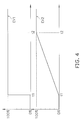
- FIG. 4 includes charts showing variation with time in opening degree of the high pressure side electric valve and variation with time in opening degree of the low pressure side electric valve in the present modification.
- An upper chart in FIG. 4 shows EV1 as variation with time in opening degree of the high pressure side electric valve.
- a lower chart in FIG. 4 shows EV2 as variation with time in opening degree of the low pressure side electric valve.
- the horizontal axis indicates time, whereas the vertical axis indicates the opening degree (%) of the high pressure side electric valve and that of the low pressure side electric valve.
- Both of the charts in FIG. 4 share the horizontal axis.
- Point-of-time t1 at which the opening degree of the high pressure side electric valve becomes 100% is a point of time at which the opening degree of the low pressure side electric valve begins to increase from 0%.
- the opening degree of the low pressure side electric valve gradually increases from 0% to 100%.
- Point-of-time t2 at which the opening degree of the low pressure side electric valve becomes 100% is a point of time at which the refrigerant circuit 2 is completely equalized in pressure.
- the controller 5 may be further configured to perform a control of fully opening the high pressure side electric valve after the capacity of the compressor 11 begins to increase in operational activation of the air conditioning apparatus 1.
- the controller 5 may be configured to perform the control of fully opening the high pressure side electric valve either after at a point of time when the rotation speed of the motor of the compressor 11 begins to increase from zero or after a point of time when the compressor 11 begins to discharge the refrigerant at high pressure.
- the refrigerant remaining in the refrigerant circuit 2 before operational activation of the air conditioning apparatus 1, can be fed to the receiver 15 as much as possible by fully opening the high pressure side electric valve after the compressor 11 begins to increase in refrigerant discharging capacity.
- the controller 5 may be further configured to perform a control of starting a normal operation after operational activation of the air conditioning apparatus 1 when a predetermined period of time has elapsed or when the temperature of the refrigerant discharged from the compressor 11 has elevated to a predetermined target value.
- the normal operation is an operation performed by the air conditioning apparatus 1 for conditioning the indoor air. Accordingly, the controller 5 can start the normal operation after the refrigerant circuit 2 is sufficiently equalized in pressure in operational activation of the air conditioning apparatus 1.
- the controller 5 may be configured to perform a control of decreasing the opening degree of the high pressure side electric valve from 100% to a predetermined opening degree in starting the normal operation after the refrigerant circuit 2 is completely equalized in pressure.
- the predetermined opening degree refers to an opening degree preliminarily set in accordance with either the operating mode of the air conditioning apparatus 1 or a target value of the degree of supercooling of the refrigerant, or alternatively, an opening degree arbitrarily determined in accordance with the operating condition of the air conditioning apparatus 1.
- the predetermined opening degree has a value greater than 0% and less than 100%.
- the controller 5 may be configured to perform a control of decreasing the opening degree of the high pressure side electric valve from 100% to a predetermined opening degree while increasing the opening degree of the low pressure side electric valve from 0% after fully opening the high pressure side electric valve.
- the predetermined opening degree refers to an opening degree preliminarily set in accordance with the operating mode of the air conditioning apparatus 1, or alternatively, an opening degree arbitrarily determined in accordance with the operating condition of the air conditioning apparatus 1.
- the predetermined opening degree has a value greater than 0% and less than 100%.
- the controller 5 is configured to perform the control of increasing the opening degree of the low pressure side electric valve stepwise from 0% to 100% after fully opening the high pressure side electric valve.
- the controller 5 may be configured to perform a control of increasing the opening degree of the low pressure side electric valve stepwise from 0% to a predetermined opening degree after fully opening the high pressure side electric valve.
- the predetermined opening degree refers to an opening degree preliminarily set in accordance with either the operating mode of the air conditioning apparatus 1 or a target value of the degree of dryness of the refrigerant, or alternatively, refers to an opening degree arbitrarily determined in accordance with the operating condition of the air conditioning apparatus 1.
- the predetermined opening degree has a value greater than 0% and less than 100%.
- the opening degree of the low pressure side electric valve has a predetermined value less than 100% in starting the normal operation after the refrigerant circuit 2 is completely equalized in pressure.
- the controller 5 may be configured to perform a control of gradually increasing the opening degree of the low pressure side electric valve from 0% to a predetermined opening degree after fully opening the high pressure side electric valve.
- FIG. 5 includes charts showing variation with time in opening degree of the high pressure side electric valve and variation with time in opening degree of the low pressure side electric valve as an example of the combination.
- An upper chart in FIG. 5 shows EV1 as variation with time in opening degree of the high pressure side electric valve.
- a lower chart in FIG. 5 shows EV2 as variation with time in opening degree of the low pressure side electric valve.
- the horizontal axis indicates time
- the vertical axis indicates the opening degree (%) of the high pressure side electric valve and that of the low pressure side electric valve.
- Both of the charts in FIG. 5 share the horizontal axis.
- Point-of-time t1 at which the opening degree of the high pressure side electric valve becomes 100% is a point of time at which the opening degree of the low pressure side electric valve begins to increase from 0%.
- the opening degree of the low pressure side electric valve increases stepwise from 0% to 40%.
- point-of-time t2 at which the opening degree of the low pressure side electric valve becomes 40% is a point of time at which the refrigerant circuit 2 is completely equalized in pressure. At point-of-time t2, the opening degree of the high pressure side electric valve decreases from 100% to 60%.
- point of time at which the refrigerant circuit 2 is completely equalized in pressure may not be matched with the point of time at which the opening degree of the low pressure side electric valve is a predetermined opening degree.
- point-of-time t2 at which the opening degree of the low pressure side electric valve is 40% may not be the point of time at which the refrigerant circuit 2 is completely equalized in pressure.
- the refrigerant circuit 2 may further include a gas injection channel for injecting the refrigerant in a gaseous state to the suction pipe 11 a of the compressor 11.
- FIG. 6 is a block diagram of an air conditioning apparatus 101 in the present modification.
- the air conditioning apparatus 101 further include a gas injection pipe 18, a gas injection valve 19 and a capillary tube 21 in addition to the respective devices included in the air conditioning apparatus 1 of the present embodiment.
- the reference signs shown in FIG. 1 are also assigned to constituent elements in FIG. 6 when these constituent elements are commonly included in the air conditioning apparatus 1 of the present embodiment. Differences between the air conditioning apparatus 101 and the air conditioning apparatus 1 of the present embodiment will be hereinafter mainly explained.
- the gas injection pipe 18 is a pipe connecting the receiver 15 and the suction pipe 11 a of the compressor 11.
- the gas injection pipe 18 is a pipe for injecting the refrigerant in a gaseous state accumulated in the receiver 15 into the suction pipe 11 a of the compressor 11. It is possible to regulate the amount of the refrigerant in the receiver 15 and the degree of dryness or the degree of superheat of the refrigerant sucked into the compressor 11 by injection of the refrigerant through the gas injection pipe 18.
- the gas injection valve 19 is an electromagnetic valve attached to the gas injection pipe 18.
- the pressure of the refrigerant in a gaseous state accumulated in the receiver 15 is higher than that of the refrigerant in a gaseous state flowing through the suction pipe 11 a of the compressor 11.
- the gas injection valve 19 is opened, the refrigerant in a gaseous state accumulated in the receiver 15 is configured to be supplied to the suction pipe 11 a of the compressor 11 via the gas injection pipe 18 and the capillary tube 21.
- the gas injection valve 19 is closed, the refrigerant in a gaseous state accumulated in the receiver 15 is not configured to be supplied to the suction pipe 11a of the compressor 11.
- the gas injection valve 19 is configured to be kept closed for preventing the refrigerant accumulated in the receiver 15 from returning to the compressor 11.
- the capillary tube 21 is a thin tube attached to the gas injection pipe 18. As shown in FIG. 6 , the capillary tube 21 is attached between the gas injection valve 19 and the suction pipe 11 a of the compressor 11. The capillary tube 21 causes throttle expansion of the refrigerant and acts as resistance against the flow of the refrigerant. The refrigerant is reduced in pressure by passage through the capillary tube 21.
- the opening degree of the gas injection valve 19 is increased to increase the amount of the refrigerant flowing through the gas injection pipe 18. Accordingly, the refrigerant to be sucked into the compressor 11 is reduced in temperature, whereby elevation in temperature of the compressor 11 can be inhibited.
- the opening degree of the gas injection valve 19 is reduced to reduce the amount of the refrigerant flowing through the gas injection pipe 18. Accordingly, reduction in temperature of the refrigerant to be sucked into the compressor 11 is suppressed to the lowest possible level, and simultaneously, the flow rate of the refrigerant passing through the indoor heat exchanger 17 is increased as much as possible, whereby efficiency in heat exchange of the indoor heat exchanger 17 can be enhanced.
- the controller 5 is further capable of controlling the opening degree of the gas injection valve 19.
- the controller 5 Before operational activation of the air conditioning apparatus 101, the controller 5 is configured to keep the gas injection valve 19 in the closed state. Accordingly, the refrigerant in a liquid state accumulated in the receiver 15 is prevented from flowing into the suction pipe 11 a of the compressor 11 through the gas injection pipe 18. Therefore, the air conditioning apparatus 101 can prevent occurrence of liquid returning when the refrigerant circuit 2 is equalized in pressure in operational activation.
- a refrigeration apparatus can prevent occurrence of liquid returning when a refrigerant circuit is equalized in pressure in activation.
Landscapes
- Engineering & Computer Science (AREA)
- Physics & Mathematics (AREA)
- Mechanical Engineering (AREA)
- Thermal Sciences (AREA)
- General Engineering & Computer Science (AREA)
- Air Conditioning Control Device (AREA)
- Compression-Type Refrigeration Machines With Reversible Cycles (AREA)
Abstract
Description
- The present invention relates to a refrigeration apparatus.
- A type of refrigeration apparatus has been conventionally used that includes a receiver configured to temporarily accumulate a refrigerant in a liquid state produced through compression in a compression mechanism and cooling in a heat exchanger. PTL 1 (Japan Laid-open Patent Application Publication No.
H09-72620 - However, when both of the two electric valves are fully opened in this refrigeration apparatus in order to equalize the pressure in a refrigerant circuit in activation, there is concern for occurrence of a phenomenon called liquid returning the refrigerant in a liquid state, accumulated in the receiver, is sucked into the compression mechanism via one of the electric valves without evaporating.
- It is an object of the present invention to provide a refrigeration apparatus that can prevent occurrence of liquid returning when the pressure in a refrigerant circuit is equalized in activation.
- A refrigeration apparatus according to a first aspect of the present invention is a refrigeration apparatus including a refrigerant circuit in which a compression mechanism of a variable capacity type, a first heat exchanger, a first electric valve, a receiver, a second electric valve and a second heat exchanger are connected in series. The refrigeration apparatus includes a switch mechanism and a control unit. The switch mechanism is configured to switch a flow direction of a refrigerant circulating through the refrigerant circuit. The control unit is configured to control an opened/closed state of the first electric valve and that of the second electric valve. In activation of the refrigeration apparatus, the control unit is configured to determine which of the first electric valve and the second electric valve corresponds to a high pressure side electric valve located in a high pressure part of the refrigerant circuit and is configured to fully open the high pressure side electric valve.
- The present refrigeration apparatus includes the receiver for temporarily accumulating the refrigerant in a gas-liquid dual-phase state. In the gas-liquid dual-phase state, the refrigerant exists in a liquid state and in a gaseous state. Here, the first heat exchanger is assumed as a heat exchanger installed in an outdoor space, whereas the second heat exchanger is assumed as a heat exchanger installed in an indoor space. The switch mechanism is configured to switch between a cooling operational mode and a heating operational mode. In the cooling operational mode, the refrigerant sequentially circulates through the compression mechanism, the first heat exchanger, the first electric valve, the receiver, the second electric valve, the second heat exchanger, and back to the compression mechanism. In the heating operational mode, the refrigerant sequentially circulates through the compression mechanism, the second heat exchanger, the second electric valve, the receiver, the first electric valve, the first heat exchanger, and back to the compression mechanism. The high pressure side electric valve corresponds to the first electric valve in the cooling operational mode, and corresponds to the second electric valve in the heating operational mode.
- In activation, the refrigeration apparatus is configured to fully open the high pressure side electric valve and simultaneously keep the other electric valve not corresponding to the high pressure side electric valve in the closed state, whereby the refrigerant accumulated in the heat exchanger located in the high pressure part of the refrigerant circuit is fed to the receiver while the refrigerant in a liquid state accumulated in the receiver is prevented from being fed to a suction side of the compression mechanism through the heat exchanger located in a low pressure part of the refrigerant circuit. Therefore, the present refrigeration apparatus can prevent occurrence of a phenomenon called liquid returning that the refrigerant in a liquid state accumulated in the receiver is sucked into the compression mechanism when the refrigerant circuit is equalized in pressure in activation.
- A refrigeration apparatus according to a second aspect of the present invention relates to the refrigeration apparatus according to the first aspect, and wherein in activation of the refrigeration apparatus, the control unit is configured to determine which of the first electric valve and the second electric valve corresponds to the high pressure side electric valve based on a state of the switch mechanism.
- The present refrigeration apparatus is configured to obtain the state of the switch mechanism and determine which of the first electric valve and the second electric valve corresponds to the high pressure side electric valve based on the state of the switch mechanism. The switch mechanism is, for instance, a four-way switch valve for switching the flow direction of the refrigerant in the refrigerant circuit. In activation, the present refrigeration apparatus is configured to equalize the refrigerant circuit in pressure based on the state of the switch mechanism, whereby occurrence of liquid returning can be prevented.
- A refrigeration apparatus according to a third aspect of the present invention relates to the refrigeration apparatus according to the first or second aspect, and wherein the first electric valve and the second electric valve are configured to be closed in a state before activation of the refrigeration apparatus.
- In the present refrigeration apparatus, before activation, the first electric valve and the second electric valve are configured to be in the closed states, and accordingly, the refrigerant is configured to be confined in the receiver.
- A refrigeration apparatus according to a fourth aspect of the present invention relates to the refrigeration apparatus according to any one of the first to third aspects, and wherein in activation of the refrigeration apparatus, the control unit is configured to keep a low pressure side electric valve located in a low pressure part of the refrigerant circuit in the closed state until the high pressure side electric valve is fully opened.
- In activation, the present refrigeration apparatus is configured to keep the low pressure side electric valve in the closed state until the high pressure side electric valve is fully opened, whereby the refrigerant in a liquid state accumulated in the receiver can be prevented from being sucked into the compression mechanism through the low pressure side electric valve.
- A refrigeration apparatus according to a fifth aspect of the present invention relates to the refrigeration apparatus according to the fourth aspect, and wherein in activation of the refrigeration apparatus, the control unit is configured to gradually open the low pressure side electric valve after the high pressure side electric valve is fully opened.
- In activation, the refrigeration apparatus is configured to gradually open the low pressure side electric valve after the high pressure side electric valve is fully opened, whereby the refrigerant circuit is equalized in pressure. The present refrigeration apparatus is configured to begin to open the low pressure side electric valve after the high pressure side electric valve is fully opened, whereby occurrence of liquid returning is prevented. Additionally, the present refrigeration apparatus is configured to gradually open the low pressure side electric valve so as to gradually reduce difference in pressure between the receiver and the heat exchanger located in the low pressure part of the refrigerant circuit, whereby the refrigerant in a liquid state accumulated in the receiver is prevented from rapidly and massively flowing into the compression mechanism via the low pressure side electric valve.
- A refrigeration apparatus according to a sixth aspect of the present invention relates to the refrigeration apparatus according to any one of the first to fifth aspects, and wherein in activation of the refrigeration apparatus, the control unit is configured to open the high pressure side electric valve after the compression mechanism begins to increase in capacity.
- In activation, the present refrigeration apparatus is configured to open the high pressure side electric valve after the compression mechanism begins to increase in refrigerant discharging capacity from zero, whereby the refrigerant, remaining in the refrigerant circuit before activation, can be fed to the receiver as much as possible.
- A refrigeration apparatus according to a seventh aspect of the present invention relates to the refrigeration apparatus according to any one of the first to sixth aspects. The present refrigeration apparatus further includes a gas injection channel and a gas injection valve, and wherein the gas injection valve is configured to be closed in a state before activation of the refrigeration apparatus. The gas injection channel connects the receiver and a refrigerant suction side of the compression mechanism. The gas injection valve is mounted in the gas injection channel.
- Before activation, the present refrigeration apparatus is configured to keep the gas injection valve in the closed state, whereby the refrigerant in a liquid state accumulated in the receiver is prevented from flowing into the suction side of the compression mechanism through the gas injection channel.
- A refrigeration apparatus according to an eighth aspect of the present invention relates to the refrigeration apparatus according to any one of the first to seventh aspects, and wherein after activation of the refrigeration apparatus, the refrigeration apparatus is configured to start a normal operation either when a predetermined period of time has elapsed or when a temperature of the refrigerant discharged from the compression mechanism has reached a first temperature.
- In activation, the present refrigeration apparatus can start the normal operation after the refrigerant circuit is sufficiently equalized in pressure.
- The refrigeration apparatus according to the first aspect can prevent occurrence of liquid returning when the refrigerant circuit is equalized in pressure in activation.
- The refrigeration apparatus according to the second aspect is configured to equalize the refrigerant circuit in pressure based on the state of the switch mechanism in activation, whereby occurrence of liquid returning can be prevented.
- The refrigeration apparatus according to the third aspect can keep the refrigerant confined in the receiver before activation.
- The refrigeration apparatus according to the fourth aspect can prevent the refrigerant in a liquid state accumulated in the receiver from being sucked into the compression mechanism through the low pressure side electric valve in activation.
- The refrigeration apparatus according to the fifth aspect is configured to gradually open the low pressure side electric valve in activation, whereby the refrigerant in a liquid state accumulated in the receiver is prevented from rapidly and massively flowing into the compression mechanism via the low pressure side electric valve.
- The refrigeration apparatus according to the sixth aspect can feed the refrigerant, remaining in the refrigerant circuit before activation, to the receiver as much as possible.
- The refrigeration apparatus according to the seventh aspect can prevent the refrigerant in a liquid state accumulated in the receiver from flowing into the suction side of the compression mechanism through the gas injection channel before activation.
- The refrigeration apparatus according to the eighth aspect can start the normal operation after the refrigerant circuit is sufficiently equalized in pressure in activation.
-
-
FIG. 1 is a block diagram of an air conditioning apparatus according to an embodiment. -
FIG. 2 is a Mollier diagram of a refrigerant and shows a refrigeration cycle in the air conditioning apparatus. -
FIG. 3 includes charts showing variation with time in opening degree of a high pressure side electric valve and variation with time in opening degree of a low pressure side electric valve. -
FIG. 4 includes charts showing variation with time in opening degree of the high pressure side electric valve and variation with time in opening degree of the low pressure side electric valve in Modification A. -
FIG. 5 includes charts showing variation with time in opening degree of the high pressure side electric valve and variation with time in opening degree of the low pressure side electric valve in Modification D. -
FIG. 6 is a block diagram of an air conditioning apparatus in Modification E. - A refrigeration apparatus according to an embodiment of the present invention will be explained with reference to drawings.
FIG. 1 is a block diagram of an air conditioning apparatus 1 provided as a refrigeration apparatus according to the present embodiment. The air conditioning apparatus 1 is an apparatus configured to perform a cooling operation and a heating operation with a fluorocarbon refrigerant (R410A, R32, etc.). The air conditioning apparatus 1 mainly includes a refrigerant circuit 2, anindoor fan 3, anoutdoor fan 4 and a controller 5. The refrigerant circuit 2 is mainly composed of acompressor 11, a four-way switch valve 12, anoutdoor heat exchanger 13, a firstelectric expansion valve 14, areceiver 15, a secondelectric expansion valve 16 and anindoor heat exchanger 17. The respective devices, composing the refrigerant circuit 2, are connected through refrigerant piping. - The air conditioning apparatus 1 is an air conditioning apparatus of a split type composed of an
outdoor unit 10 and anindoor unit 20. Theoutdoor unit 10 mainly includes thecompressor 11, the four-way switch valve 12, theoutdoor heat exchanger 13, the firstelectric expansion valve 14, thereceiver 15, the secondelectric expansion valve 16, theoutdoor fan 4 and the controller 5. Theindoor unit 20 mainly includes theindoor heat exchanger 17 and theindoor fan 3. As shown inFIG. 1 , theoutdoor unit 10 is connected to theindoor unit 20 through first communication piping 31 and second communication piping 32. Next, the respective devices composing the refrigerant circuit 2 will be respectively explained. - The
compressor 11 is connected to a suction pipe 11 a and adischarge pipe 11 b that are part of the refrigerant piping. Thecompressor 11 is configured to suck the refrigerant in a gaseous state at low pressure from the suction pipe 11 a, compress the sucked refrigerant, and discharge the refrigerant at high temperature and high pressure to thedischarge pipe 11 b. Thecompressor 11 is a compressor of a variable capacity type that the rotation speed of a motor is controllable. - The four-
way switch valve 12 is a valve for switching the flow direction of the refrigerant in the refrigerant circuit 2 in accordance with an operating mode. The operating mode is composed of a cooling operational mode for performing the cooling operation and a heating operational mode for performing the heating operation. In the four-way switch valve 12 shown inFIG. 1 , solid line indicates a channel in the cooling operational mode whereas dashed line indicates a channel in the heating operational mode. In the cooling operational mode, the four-way switch valve 12 is configured to connect thedischarge pipe 11 b of thecompressor 11 and theoutdoor heat exchanger 13, and also, connect the suction pipe 11 a of thecompressor 11 and theindoor heat exchanger 17. In the heating operational mode, the four-way switch valve 12 is configured to connect thedischarge pipe 11 b of thecompressor 11 and theindoor heat exchanger 17, and also, connect the suction pipe 11 a of thecompressor 11 and theoutdoor heat exchanger 13. - In the cooling operational mode, the refrigerant sequentially circulates through the
compressor 11, the four-way switch valve 12, theoutdoor heat exchanger 13, the firstelectric expansion valve 14, thereceiver 15, the secondelectric expansion valve 16, theindoor heat exchanger 17, the four-way switch valve 12, and back to thecompressor 11. In the heating operational mode, the refrigerant sequentially circulates through thecompressor 11, the four-way switch valve 12, theindoor heat exchanger 17, the secondelectric expansion valve 16, thereceiver 15, the firstelectric expansion valve 14, theoutdoor heat exchanger 13, the four-way switch valve 12, and back to thecompressor 11. - In the cooling operational mode, the
outdoor heat exchanger 13 is configured to exchange heat between the refrigerant at high temperature and high pressure discharged from thecompressor 11 and the air in an outdoor space where theoutdoor unit 10 is installed. In the cooling operational mode, the refrigerant at high temperature and high pressure, flowing through theoutdoor heat exchanger 13, is configured to be cooled. In the heating operational mode, theoutdoor heat exchanger 13 is configured to exchange heat between the outdoor air and the refrigerant in a liquid state reduced in pressure by passage through the firstelectric expansion valve 14. In the heating operational mode, the refrigerant in a liquid state, flowing through theoutdoor heat exchanger 13, is configured to be heated and evaporate. - In the cooling operational mode, the first
electric expansion valve 14 is configured to reduce the pressure of the refrigerant flowing therein from theoutdoor heat exchanger 13. In the heating operational mode, the firstelectric expansion valve 14 is configured to reduce the pressure of the refrigerant in a liquid state flowing therein from thereceiver 15. - The
receiver 15 is configured to accumulate the amount of refrigerant surplus for the refrigerant circuit 2 in accordance with the operating mode and an air-conditioning load. - In the cooling operational mode, the second
electric expansion valve 16 is configured to reduce the pressure of the refrigerant in a liquid state flowing therein from thereceiver 15. In the heating operational mode, the secondelectric expansion valve 16 is configured to reduce the pressure of the refrigerant flowing therein from theindoor heat exchanger 17. - The
indoor heat exchanger 17 is connected to the secondelectric expansion valve 16 through the first communication piping 31, and is also connected to the four-way switch valve 12 through the second communication piping 32. - In the cooling operational mode, the
indoor heat exchanger 17 is configured to exchange heat between the refrigerant in a liquid state, reduced in pressure by passage through the secondelectric expansion valve 16, and the air in the indoor space where theindoor unit 20 is installed. In the cooling operational mode, the refrigerant in a liquid state, flowing through theindoor heat exchanger 17, is configured to be heated and changed into the refrigerant in a gaseous state by heat exchange and then be fed to the suction pipe 11 a of thecompressor 11. In the cooling operational mode, the indoor air is configured to be cooled and changed into conditioned air by heat exchange in theindoor heat exchanger 17. - In the heating operational mode, the
indoor heat exchanger 17 is configured to exchange heat between the refrigerant at high temperature and high pressure, flowing therein from thedischarge pipe 11 b of thecompressor 11, and the air in the indoor space where theindoor unit 20 is installed. In the heating operational mode, the refrigerant at high temperature and high pressure, flowing through theindoor heat exchanger 17, is configured to be cooled by heat exchange and then be fed to thereceiver 15. In the heating operational mode, the indoor air is configured to be heated and changed into conditioned air by heat exchange in theindoor heat exchanger 17. - The
indoor fan 3 is installed in the vicinity of theindoor heat exchanger 17 in the interior of theindoor unit 20. Theindoor fan 3 is a fan for feeding the indoor air to the interior of theindoor unit 20 and for discharging the air, heat-exchanged with the refrigerant flowing through theindoor heat exchanger 17, to the indoor space. Theindoor fan 3 is configured to discharge the cooled conditioned air into the indoor space in the cooling operational mode and discharge the heated conditioned air into the indoor space in the heating operational mode. - The
outdoor fan 4 is installed in the vicinity of theoutdoor heat exchanger 13 in the interior of theoutdoor unit 10. Theoutdoor fan 4 is a fan for feeding the outdoor air to the interior of theoutdoor unit 10 and for discharging the air, heat-exchanged with the refrigerant flowing through theoutdoor heat exchanger 13, to the outdoor space. - The controller 5 is a computer connected to the
compressor 11, the four-way switch valve 12, the firstelectric expansion valve 14, the secondelectric expansion valve 16, theindoor fan 3, theoutdoor fan 4 and so forth through communication lines. The controller 5 is capable of obtaining and controlling the capacity of thecompressor 11, the state of the four-way switch valve 12, the opening degree of the firstelectric expansion valve 14, the opening degree of the secondelectric expansion valve 16, the rotation speed of theindoor fan 3, the rotation speed of theoutdoor fan 4 and so forth. The capacity of thecompressor 11 is, for instance, the discharge rate of the refrigerant per unit time or the rotation speed of a motor provided in thecompressor 11. The state of the four-way switch valve 12 is information for indicating which of the cooling operational mode and the heating operational mode the air conditioning apparatus 1 is in. The controller 5 is configured to obtain a variety of data from the respective devices composing the refrigerant circuit 2 and control the opening degree of the firstelectric expansion valve 14 and that of the secondelectric expansion valve 16. - Operating actions of the air conditioning apparatus 1 in the cooling operational mode and the heating operational mode will be explained using
FIGS. 1 and2. FIG. 2 is a Mollier diagram (pressure-enthalpy diagram) of the refrigerant and shows a refrigeration cycle of the air conditioning apparatus 1.FIG. 2 shows dry saturated vapor line L1 of the refrigerant and saturated liquid line L2 of the refrigerant. States of the refrigerant indicated with reference signs A to E inFIG. 2 respectively correspond to those indicated with reference signs A to E inFIG. 1 in the cooling operational mode. - In
FIG. 2 , transition A to B indicates a compression step of the refrigerant in a gaseous state; transition B to C indicates a cooling step of the refrigerant; transition C to D1 indicates a first expansion step of the refrigerant; transition D2 to E indicates a second expansion step of the refrigerant; and transition E to A indicates an evaporation step of the refrigerant. During operation, the air conditioning apparatus 1 is configured to repeat a refrigeration cycle in the order of A, B, C, D1, D2, E, and back to A. - In
FIG. 2 , D1 and D2 indicate the states of the refrigerant within thereceiver 15. D1 indicates the refrigerant in a gas-liquid dual-phase state that flows into thereceiver 15. D2 indicates the refrigerant in a saturated liquid state that is accumulated in thereceiver 15 and flows out therefrom. D2 is plotted on saturated liquid line L2. - In the cooling operational mode, the four-
way switch valve 12 is in the state indicated with solid line inFIG. 1 . In other words, the discharge side of thecompressor 11 is connected to the high temperature side of theoutdoor heat exchanger 13, while the suction side of thecompressor 11 is connected to the high temperature side of theindoor heat exchanger 17. - In the cooling operational mode, when the
compressor 11 is activated, the refrigerant in a gaseous state at low pressure is configured to be sucked into and compressed in thecompressor 11. Accordingly, the refrigerant in a gaseous state at high temperature and high pressure is configured to be discharged from thecompressor 11. Next, the refrigerant in a gaseous state at high temperature and high pressure is configured to be fed to theoutdoor heat exchanger 13 via the four-way switch valve 12, be cooled in theoutdoor heat exchanger 13, and be changed into the refrigerant in a liquid state. Next, the refrigerant in a liquid state is configured to be reduced in pressure by passage through the firstelectric expansion valve 14 and be changed into the refrigerant in a gas-liquid dual-phase state. Next, the refrigerant in a gas-liquid dual-phase state is configured to be fed to thereceiver 15 and be partially accumulated in thereceiver 15 as the refrigerant in a liquid state. Next, the refrigerant in a liquid state, flowing out from thereceiver 15, is configured to be reduced in pressure by passage through the secondelectric expansion valve 16 and be changed into the refrigerant in a gas-liquid dual-phase state. Next, the refrigerant in a gas-liquid dual-phase state is configured to be heated and evaporates in theindoor heat exchanger 17 and be changed into the refrigerant in a gaseous state. In theindoor heat exchanger 17, the indoor air is configured to be cooled by heat exchange with the refrigerant. Next, the refrigerant in a gaseous state is configured to be again sucked into thecompressor 11 via the four-way switch valve 12. In the cooling operational mode, the controller 5 is configured to control the respective devices of the air conditioning apparatus 1 in order to perform the aforementioned control. - In the heating operational mode, the four-
way switch valve 12 is in the state indicated with dotted line inFIG. 1 . In other words, the discharge side of thecompressor 11 is connected to the high temperature side of theindoor heat exchanger 17, while the suction side of thecompressor 11 is connected to the high temperature side of theoutdoor heat exchanger 13. - In the heating operational mode, when the
compressor 11 is activated, the refrigerant in a gaseous state at low pressure is configured to be sucked into and compressed in thecompressor 11. Accordingly, the refrigerant in a gaseous state at high temperature and high pressure is configured to be discharged from thecompressor 11. Next, the refrigerant in a gaseous state at high temperature and high pressure is configured to be fed to theindoor heat exchanger 17 via the four-way switch valve 12, be cooled in theindoor heat exchanger 17, and be changed into the refrigerant in a liquid state. In theindoor heat exchanger 17, the indoor air is configured to be heated by heat exchange with the refrigerant. Next, the refrigerant in a liquid state is configured to be reduced in pressure by passage through the secondelectric expansion valve 16 and be changed into the refrigerant in a gas-liquid dual-phase state. Next, the refrigerant in a gas-liquid dual-phase state is configured to be fed to thereceiver 15 and be partially accumulated in thereceiver 15 as the refrigerant in a liquid state. Next, the refrigerant in a liquid state, flowing out from thereceiver 15, is configured to be reduced in pressure by passage through the firstelectric expansion valve 14 and be changed into the refrigerant in a gas-liquid dual-phase state. Next, the refrigerant in a gas-liquid dual-phase state is configured to be heated and evaporates in theoutdoor heat exchanger 13 and be changed into the refrigerant in a gaseous state. Next, the refrigerant in a gaseous state is configured to be again sucked into thecompressor 11 via the four-way switch valve 12. In the heating operational mode, the controller 5 is configured to control the respective devices of the air conditioning apparatus 1 in order to perform the aforementioned control. - Before operational activation of the air conditioning apparatus 1, the first
electric expansion valve 14 and the secondelectric expansion valve 16 are configured to be kept closed. In operational activation of the air conditioning apparatus 1, the controller 5 is configured to perform a control of fully opening a high pressure side electric valve located in a high pressure part of the refrigerant circuit 2 and simultaneously keeping a low pressure side electric valve located in a low pressure part of the refrigerant circuit 2 in a closed state. The high pressure side electric valve is an electric expansion valve through which the refrigerant at high temperature and high pressure passes. The high pressure side electric valve corresponds to the firstelectric expansion valve 14 in the cooling operational mode, and corresponds to the secondelectric expansion valve 16 in the heating operational mode. - In operational activation of the air conditioning apparatus 1, the controller 5 is configured to determine which of the first
electric expansion valve 14 and the secondelectric expansion valve 16 corresponds to the high pressure side electric valve and is configured to fully open the high pressure side electric valve. Specifically, the controller 5 is configured to obtain the state of the four-way switch valve 12 and determine which of the cooling operational mode and the heating operational mode the air conditioning apparatus 1 is in. In operational activation of the air conditioning apparatus 1, when the four-way switch valve 12 is in the state indicated with solid line inFIG. 1 , the controller 5 is configured to determine that the air conditioning apparatus 1 is in the cooling operational mode, and is configured to fully open the firstelectric expansion valve 14 corresponding to the high pressure side electric valve and keep the secondelectric expansion valve 16 corresponding to the low pressure side electric valve in the closed state. Contrarily, when the four-way switch valve 12 is in the state indicated with dotted line inFIG. 1 , the controller 5 is configured to determine that the air conditioning apparatus 1 is in the heating operational mode, and is configured to fully open the secondelectric expansion valve 16 corresponding to the high pressure side electric valve and keep the firstelectric expansion valve 14 corresponding to the low pressure side electric valve in the closed state. - Additionally, in operational activation of the air conditioning apparatus 1, the controller 5 is configured to perform a control of keeping the low pressure side electric valve in the closed state until the high pressure side electric valve is fully opened, and then, gradually opening the low pressure side electric valve after the high pressure side electric valve is fully opened. In the cooling operational mode, the controller 5 is configured to perform a control of keeping the second
electric expansion valve 16 in the closed state until the firstelectric expansion valve 14 is fully opened, and then, gradually opening the secondelectric expansion valve 16 after the firstelectric expansion valve 14 is fully opened. In the heating operational mode, the controller 5 is configured to perform a control of keeping the firstelectric expansion valve 14 in the closed state until the secondelectric expansion valve 16 is fully opened, and then, gradually opening the firstelectric expansion valve 14 after the secondelectric expansion valve 16 is fully opened.FIG. 3 includes charts showing variation with time in opening degree of the high pressure side electric valve and variation with time in opening degree of the low pressure side electric valve in operational activation of the air conditioning apparatus 1. An upper chart inFIG. 3 shows EV1 as variation with time in opening degree of the high pressure side electric valve. A lower chart inFIG. 3 shows EV2 as variation with time in opening degree of the low pressure side electric valve. InFIG. 3 , the horizontal axis indicates time, whereas the vertical axis indicates the opening degree (%) of the high pressure side electric valve and that of the low pressure side electric valve. Both of the charts inFIG. 3 share the horizontal axis. The high pressure side electric valve and the low pressure side electric valve are configured to be fully closed when the opening degree is 0% and be fully opened when the opening degree is 100%. Point-of-time t1 at which the opening degree of the high pressure side electric valve becomes 100% is a point of time at which the opening degree of the low pressure side electric valve begins to increase from 0%. The opening degree of the low pressure side electric valve increases stepwise from 0% to 100%. Point-of-time t2 at which the opening degree of the low pressure side electric valve becomes 100% is a point of time at which the refrigerant circuit 2 is completely equalized in pressure. - In the refrigerant circuit 2 of the air conditioning apparatus 1, the
receiver 15 is interposed between the firstelectric expansion valve 14 and the secondelectric expansion valve 16. The firstelectric expansion valve 14 and the secondelectric expansion valve 16 are configured to be closed when the operation of the air conditioning apparatus 1 is deactivated. Therefore, in operational activation of the air conditioning apparatus 1, a part in which the refrigerant pressure is high and a part in which the refrigerant pressure is low exist in the refrigerant circuit 2. To avoid acute variation in pressure of the refrigerant in the refrigerant circuit 2 in operational activation, the air conditioning apparatus 1 is required to equalize the refrigerant circuit 2 in pressure in operational activation. - In operational activation of the air conditioning apparatus 1 under the cooling operational mode, the air conditioning apparatus 1 is configured to fully open the first
electric expansion valve 14 corresponding to the high pressure side electric valve and simultaneously keep the secondelectric expansion valve 16 corresponding to the low pressure side electric valve in the closed state, whereby the refrigerant accumulated in theoutdoor heat exchanger 13 is fed to thereceiver 15 while the refrigerant in a liquid state accumulated in thereceiver 15 is prevented from passing through theindoor heat exchanger 17 and then being fed to the suction pipe 11 a of thecompressor 11. Contrarily, in operational activation of the air conditioning apparatus 1 under the heating operational mode, the air conditioning apparatus 1 is configured to fully open the secondelectric expansion valve 16 corresponding to the high pressure side electric valve and simultaneously keep the firstelectric expansion valve 14 corresponding to the low pressure side electric valve in the closed state, whereby the refrigerant accumulated in theindoor heat exchanger 17 is fed to thereceiver 15 while the refrigerant in a liquid state accumulated in thereceiver 15 is prevented from passing through theoutdoor heat exchanger 13 and then being fed to the suction pipe 11 a of thecompressor 11. In occurrence of a phenomenon called liquid returning that the refrigerant in a liquid state accumulated in thereceiver 15 is sucked into thecompressor 11, this becomes a cause of breakdown of thecompressor 11. Therefore, the air conditioning apparatus 1 can prevent occurrence of liquid returning when the refrigerant circuit 2 is equalized in pressure in operational activation. - Additionally, the controller 5 of the air conditioning apparatus 1 is configured to determine which of the first
electric expansion valve 14 and the secondelectric expansion valve 16 corresponds to the high pressure side electric valve based on the state of the four-way switch valve 12. Therefore, the controller 5 can perform an opening degree control of fully opening the high pressure side electric valve and simultaneously keeping the low pressure side electric valve in the closed state in operational activation of the air conditioning apparatus 1 without memorizing which of the cooling operational mode and the heating operational mode the operating mode is currently in. - Incidentally, immediately after switching the operating mode using a remote controller or so forth for controlling the air conditioning apparatus 1, there are chances that the state of the four-
way switch valve 12, corresponding to the operating mode memorized in the remote controller or so forth, is not matched with the actual state of the four-way switch valve 12. However, the controller 5 is configured to obtain the actual state of the four-way switch valve 12 and determine which of the firstelectric expansion valve 14 and the secondelectric expansion valve 16 corresponds to the high pressure side electric valve. Hence, the controller 5 can reliably perform the aforementioned opening degree control. Therefore, the air conditioning apparatus 1 can reliably prevent occurrence of liquid returning in operational activation. - Additionally, the controller 5 can confine the refrigerant in the
receiver 15 by keeping both of the firstelectric expansion valve 14 and the secondelectric expansion valve 16 in closed states before operational activation of the air conditioning apparatus 1. - Moreover, the controller 5 can prevent the refrigerant in a liquid state accumulated in the
receiver 15 from being sucked into thecompressor 11 via the low pressure side electric valve in a step of equalizing the refrigerant circuit 2 in pressure by beginning to open the low pressure side electric valve after fully opening the high pressure side electric valve in operational activation of the air conditioning apparatus 1. - Furthermore, the controller 5 can prevent the refrigerant in a liquid state accumulated in the
receiver 15 from rapidly and massively flowing into thecompressor 11 via the low pressure side electric valve in the step of equalizing the refrigerant circuit 2 in pressure by gradually opening the low pressure side electric valve after fully opening the high pressure side electric valve in operational activation of the air conditioning apparatus 1. There exists difference in pressure between the refrigerant in the piping on the upstream side of the low pressure side electric valve and that in the piping on the downstream side of the low pressure side electric valve. Therefore, there are chances that when the low pressure side electric valve is rapidly opened, the large amount of refrigerant passes through the low pressure side electric valve due to the difference in pressure and thereby liquid returning occurs. The controller 5 can prevent occurrence of liquid returning by performing a control of increasing stepwise the opening degree of the low pressure side electric valve. - Specific configurations of the present embodiment can be changed without departing from the scope of the present invention. Modifications applicable to the present embodiment will be hereinafter explained.
- In the present embodiment, the controller 5 is configured to increase the opening degree of the low pressure side electric valve stepwise from 0% to 100% after fully opening the high pressure side electric valve. However, the controller 5 may be configured to gradually increase the opening degree of the low pressure side electric valve from 0% to 100% after fully opening the high pressure side electric valve.
FIG. 4 includes charts showing variation with time in opening degree of the high pressure side electric valve and variation with time in opening degree of the low pressure side electric valve in the present modification. An upper chart inFIG. 4 shows EV1 as variation with time in opening degree of the high pressure side electric valve. A lower chart inFIG. 4 shows EV2 as variation with time in opening degree of the low pressure side electric valve. InFIG. 4 , the horizontal axis indicates time, whereas the vertical axis indicates the opening degree (%) of the high pressure side electric valve and that of the low pressure side electric valve. Both of the charts inFIG. 4 share the horizontal axis. Point-of-time t1 at which the opening degree of the high pressure side electric valve becomes 100% is a point of time at which the opening degree of the low pressure side electric valve begins to increase from 0%. The opening degree of the low pressure side electric valve gradually increases from 0% to 100%. Point-of-time t2 at which the opening degree of the low pressure side electric valve becomes 100% is a point of time at which the refrigerant circuit 2 is completely equalized in pressure. - In the present embodiment, the controller 5 may be further configured to perform a control of fully opening the high pressure side electric valve after the capacity of the
compressor 11 begins to increase in operational activation of the air conditioning apparatus 1. For example, the controller 5 may be configured to perform the control of fully opening the high pressure side electric valve either after at a point of time when the rotation speed of the motor of thecompressor 11 begins to increase from zero or after a point of time when thecompressor 11 begins to discharge the refrigerant at high pressure. - In the present modification, the refrigerant, remaining in the refrigerant circuit 2 before operational activation of the air conditioning apparatus 1, can be fed to the
receiver 15 as much as possible by fully opening the high pressure side electric valve after thecompressor 11 begins to increase in refrigerant discharging capacity. - In the present embodiment, the controller 5 may be further configured to perform a control of starting a normal operation after operational activation of the air conditioning apparatus 1 when a predetermined period of time has elapsed or when the temperature of the refrigerant discharged from the
compressor 11 has elevated to a predetermined target value. The normal operation is an operation performed by the air conditioning apparatus 1 for conditioning the indoor air. Accordingly, the controller 5 can start the normal operation after the refrigerant circuit 2 is sufficiently equalized in pressure in operational activation of the air conditioning apparatus 1. - Additionally, the controller 5 may be configured to perform a control of decreasing the opening degree of the high pressure side electric valve from 100% to a predetermined opening degree in starting the normal operation after the refrigerant circuit 2 is completely equalized in pressure. Here, the predetermined opening degree refers to an opening degree preliminarily set in accordance with either the operating mode of the air conditioning apparatus 1 or a target value of the degree of supercooling of the refrigerant, or alternatively, an opening degree arbitrarily determined in accordance with the operating condition of the air conditioning apparatus 1. The predetermined opening degree has a value greater than 0% and less than 100%.
- Alternatively, the controller 5 may be configured to perform a control of decreasing the opening degree of the high pressure side electric valve from 100% to a predetermined opening degree while increasing the opening degree of the low pressure side electric valve from 0% after fully opening the high pressure side electric valve. Here, the predetermined opening degree refers to an opening degree preliminarily set in accordance with the operating mode of the air conditioning apparatus 1, or alternatively, an opening degree arbitrarily determined in accordance with the operating condition of the air conditioning apparatus 1. The predetermined opening degree has a value greater than 0% and less than 100%.
- In the present embodiment, the controller 5 is configured to perform the control of increasing the opening degree of the low pressure side electric valve stepwise from 0% to 100% after fully opening the high pressure side electric valve. However, the controller 5 may be configured to perform a control of increasing the opening degree of the low pressure side electric valve stepwise from 0% to a predetermined opening degree after fully opening the high pressure side electric valve. Here, the predetermined opening degree refers to an opening degree preliminarily set in accordance with either the operating mode of the air conditioning apparatus 1 or a target value of the degree of dryness of the refrigerant, or alternatively, refers to an opening degree arbitrarily determined in accordance with the operating condition of the air conditioning apparatus 1. The predetermined opening degree has a value greater than 0% and less than 100%. In this case, the opening degree of the low pressure side electric valve has a predetermined value less than 100% in starting the normal operation after the refrigerant circuit 2 is completely equalized in pressure. The controller 5 may be configured to perform a control of gradually increasing the opening degree of the low pressure side electric valve from 0% to a predetermined opening degree after fully opening the high pressure side electric valve.
- Additionally, the opening degree control of the present modification may be combined with that of Modification C.
FIG. 5 includes charts showing variation with time in opening degree of the high pressure side electric valve and variation with time in opening degree of the low pressure side electric valve as an example of the combination. An upper chart inFIG. 5 shows EV1 as variation with time in opening degree of the high pressure side electric valve. A lower chart inFIG. 5 shows EV2 as variation with time in opening degree of the low pressure side electric valve. InFIG. 5 , the horizontal axis indicates time, whereas the vertical axis indicates the opening degree (%) of the high pressure side electric valve and that of the low pressure side electric valve. Both of the charts inFIG. 5 share the horizontal axis. Point-of-time t1 at which the opening degree of the high pressure side electric valve becomes 100% is a point of time at which the opening degree of the low pressure side electric valve begins to increase from 0%. The opening degree of the low pressure side electric valve increases stepwise from 0% to 40%. InFIG. 5 , point-of-time t2 at which the opening degree of the low pressure side electric valve becomes 40% is a point of time at which the refrigerant circuit 2 is completely equalized in pressure. At point-of-time t2, the opening degree of the high pressure side electric valve decreases from 100% to 60%. - It should be noted that the point of time at which the refrigerant circuit 2 is completely equalized in pressure may not be matched with the point of time at which the opening degree of the low pressure side electric valve is a predetermined opening degree. For example, in
FIG. 5 , point-of-time t2 at which the opening degree of the low pressure side electric valve is 40% may not be the point of time at which the refrigerant circuit 2 is completely equalized in pressure. - In the present embodiment, the refrigerant circuit 2 may further include a gas injection channel for injecting the refrigerant in a gaseous state to the suction pipe 11 a of the
compressor 11.FIG. 6 is a block diagram of anair conditioning apparatus 101 in the present modification. Theair conditioning apparatus 101 further include agas injection pipe 18, agas injection valve 19 and acapillary tube 21 in addition to the respective devices included in the air conditioning apparatus 1 of the present embodiment. The reference signs shown inFIG. 1 are also assigned to constituent elements inFIG. 6 when these constituent elements are commonly included in the air conditioning apparatus 1 of the present embodiment. Differences between theair conditioning apparatus 101 and the air conditioning apparatus 1 of the present embodiment will be hereinafter mainly explained. - The
gas injection pipe 18 is a pipe connecting thereceiver 15 and the suction pipe 11 a of thecompressor 11. Thegas injection pipe 18 is a pipe for injecting the refrigerant in a gaseous state accumulated in thereceiver 15 into the suction pipe 11 a of thecompressor 11. It is possible to regulate the amount of the refrigerant in thereceiver 15 and the degree of dryness or the degree of superheat of the refrigerant sucked into thecompressor 11 by injection of the refrigerant through thegas injection pipe 18. - The
gas injection valve 19 is an electromagnetic valve attached to thegas injection pipe 18. In operation of the air conditioning apparatus 1, the pressure of the refrigerant in a gaseous state accumulated in thereceiver 15 is higher than that of the refrigerant in a gaseous state flowing through the suction pipe 11 a of thecompressor 11. When thegas injection valve 19 is opened, the refrigerant in a gaseous state accumulated in thereceiver 15 is configured to be supplied to the suction pipe 11 a of thecompressor 11 via thegas injection pipe 18 and thecapillary tube 21. When thegas injection valve 19 is closed, the refrigerant in a gaseous state accumulated in thereceiver 15 is not configured to be supplied to the suction pipe 11a of thecompressor 11. Before operational activation of the air conditioning apparatus 1, thegas injection valve 19 is configured to be kept closed for preventing the refrigerant accumulated in thereceiver 15 from returning to thecompressor 11. - The
capillary tube 21 is a thin tube attached to thegas injection pipe 18. As shown inFIG. 6 , thecapillary tube 21 is attached between thegas injection valve 19 and the suction pipe 11 a of thecompressor 11. Thecapillary tube 21 causes throttle expansion of the refrigerant and acts as resistance against the flow of the refrigerant. The refrigerant is reduced in pressure by passage through thecapillary tube 21. - In the cooling operational mode, the opening degree of the
gas injection valve 19 is increased to increase the amount of the refrigerant flowing through thegas injection pipe 18. Accordingly, the refrigerant to be sucked into thecompressor 11 is reduced in temperature, whereby elevation in temperature of thecompressor 11 can be inhibited. On the other hand, in the heating operational mode, the opening degree of thegas injection valve 19 is reduced to reduce the amount of the refrigerant flowing through thegas injection pipe 18. Accordingly, reduction in temperature of the refrigerant to be sucked into thecompressor 11 is suppressed to the lowest possible level, and simultaneously, the flow rate of the refrigerant passing through theindoor heat exchanger 17 is increased as much as possible, whereby efficiency in heat exchange of theindoor heat exchanger 17 can be enhanced. - In the present modification, the controller 5 is further capable of controlling the opening degree of the
gas injection valve 19. Before operational activation of theair conditioning apparatus 101, the controller 5 is configured to keep thegas injection valve 19 in the closed state. Accordingly, the refrigerant in a liquid state accumulated in thereceiver 15 is prevented from flowing into the suction pipe 11 a of thecompressor 11 through thegas injection pipe 18. Therefore, theair conditioning apparatus 101 can prevent occurrence of liquid returning when the refrigerant circuit 2 is equalized in pressure in operational activation. - A refrigeration apparatus according to the present invention can prevent occurrence of liquid returning when a refrigerant circuit is equalized in pressure in activation.
-
- 1
- Air conditioning apparatus (Refrigeration apparatus)
- 2
- Refrigerant circuit
- 5
- Controller (Control unit)
- 11
- Compressor (Compression mechanism)
- 12
- Four-way switch valve (Switch mechanism)
- 13
- Outdoor heat exchanger (First heat exchanger)
- 14
- First electric expansion valve (First electric valve)
- 15
- Receiver
- 16
- Second electric expansion valve (Second electric valve)
- 17
- Indoor heat exchanger (Second heat exchanger)
- 18
- Gas injection pipe (Gas injection channel)
- 19
- Gas injection valve
- PTL 1: Japan Laid-open Patent Application Publication No.
H09-72620
Claims (8)
- A refrigeration apparatus (1) including a refrigerant circuit (2) in which a compression mechanism (11) of a variable capacity type, a first heat exchanger (13), a first electric valve (14), a receiver (15), a second electric valve (16) and a second heat exchanger (17) are connected in series, the refrigeration apparatus (1) comprising:a switch mechanism (12) configured to switch a flow direction of a refrigerant circulating through the refrigerant circuit; and
a control unit (5) configured to control an opened/closed state of the first electric valve and an opened/closed state of the second electric valve,wherein, in activation of the refrigeration apparatus, the control unit is configured to determine which of the first electric valve and the second electric valve corresponds to a high pressure side electric valve located in a high pressure part of the refrigerant circuit and is configured to fully open the high pressure side electric valve. - The refrigeration apparatus recited in claim 1, wherein
in activation of the refrigeration apparatus, the control unit is configured to determine which of the first electric valve and the second electric valve corresponds to the high pressure side electric valve based on a state of the switch mechanism. - The refrigeration apparatus recited in claim 1 or 2, wherein
the first electric valve and the second electric valve are configured to be closed in a state before activation of the refrigeration apparatus. - The refrigeration apparatus recited in any one of claims 1 to 3, wherein
in activation of the refrigeration apparatus, the control unit is configured to keep a low pressure side electric valve located in a low pressure part of the refrigerant circuit in the closed state until the high pressure side electric valve is fully opened. - The refrigeration apparatus recited in claim 4, wherein
in activation of the refrigeration apparatus, the control unit is configured to gradually open the low pressure side electric valve after the high pressure side electric valve is fully opened. - The refrigeration apparatus recited in any one of claims 1 to 5, wherein
in activation of the refrigeration apparatus, the control unit is configured to open the high pressure side electric valve after the compression mechanism begins to increase in capacity. - The refrigeration apparatus recited in any one of claims 1 to 6, further comprising:a gas injection channel (18) connecting the receiver and a refrigerant suction side of the compression mechanism; anda gas injection valve (19) mounted in the gas injection channel,wherein the gas injection valve is configured to be closed in a state before activation of the refrigeration apparatus.
- The refrigeration apparatus recited in any one of claims 1 to 7, wherein
after activation of the refrigeration apparatus, the refrigeration apparatus is configured to start a normal operation either when a predetermined period of time has elapsed or when a temperature of the refrigerant discharged from the compression mechanism has reached a first temperature.
Applications Claiming Priority (2)
| Application Number | Priority Date | Filing Date | Title |
|---|---|---|---|
| JP2013222088A JP2015083894A (en) | 2013-10-25 | 2013-10-25 | Refrigeration equipment |
| PCT/JP2014/078214 WO2015060384A1 (en) | 2013-10-25 | 2014-10-23 | Refrigeration device |
Publications (2)
| Publication Number | Publication Date |
|---|---|
| EP3062041A1 true EP3062041A1 (en) | 2016-08-31 |
| EP3062041A4 EP3062041A4 (en) | 2017-06-07 |
Family
ID=52992973
Family Applications (1)
| Application Number | Title | Priority Date | Filing Date |
|---|---|---|---|
| EP14855297.9A Withdrawn EP3062041A4 (en) | 2013-10-25 | 2014-10-23 | Refrigeration device |
Country Status (5)
| Country | Link |
|---|---|
| EP (1) | EP3062041A4 (en) |
| JP (1) | JP2015083894A (en) |
| CN (1) | CN105593615A (en) |
| AU (1) | AU2014338081A1 (en) |
| WO (1) | WO2015060384A1 (en) |
Cited By (2)
| Publication number | Priority date | Publication date | Assignee | Title |
|---|---|---|---|---|
| EP3312528A4 (en) * | 2015-06-18 | 2019-02-27 | Daikin Industries, Ltd. | AIR CONDITIONER |
| US11435117B2 (en) | 2017-10-10 | 2022-09-06 | Mitsubishi Electric Corporation | Air-conditioning apparatus |
Families Citing this family (3)
| Publication number | Priority date | Publication date | Assignee | Title |
|---|---|---|---|---|
| DK3332181T3 (en) | 2015-08-03 | 2021-10-25 | Carrier Corp | COOLING SYSTEM AND OPERATING PROCEDURE |
| CN107576094B (en) * | 2017-07-31 | 2023-04-18 | 宁波奥克斯电气股份有限公司 | Heat pump unit and operation method thereof |
| JP7440761B2 (en) * | 2020-04-16 | 2024-02-29 | ダイキン工業株式会社 | Open valve circuit and heat pump device |
Family Cites Families (24)
| Publication number | Priority date | Publication date | Assignee | Title |
|---|---|---|---|---|
| JPH07269972A (en) * | 1994-03-31 | 1995-10-20 | Toshiba Corp | Air conditioner and control method thereof |
| JPH08200858A (en) * | 1995-01-19 | 1996-08-06 | Toyo Eng Works Ltd | Two-stage compression refrigerator |
| JP3817752B2 (en) * | 1995-02-06 | 2006-09-06 | ダイキン工業株式会社 | Air conditioner |
| JPH0972620A (en) | 1995-06-28 | 1997-03-18 | Denso Corp | Injection refrigeration system |
| JPH10220889A (en) * | 1997-02-05 | 1998-08-21 | Denso Corp | Refrigeration cycle device |
| JP4035871B2 (en) * | 1997-10-21 | 2008-01-23 | ダイキン工業株式会社 | Refrigerant circuit |
| JP3421915B2 (en) * | 1997-12-19 | 2003-06-30 | 三菱電機株式会社 | Refrigeration cycle |
| JP2001133056A (en) * | 1999-11-04 | 2001-05-18 | Mitsubishi Electric Corp | Air conditioner |
| JP4269476B2 (en) * | 2000-03-29 | 2009-05-27 | ダイキン工業株式会社 | Refrigeration equipment |
| JP4538892B2 (en) * | 2000-04-19 | 2010-09-08 | ダイキン工業株式会社 | Air conditioner using CO2 refrigerant |
| JP2001336850A (en) * | 2000-05-31 | 2001-12-07 | Denso Corp | Heat pump equipment |
| JP3819678B2 (en) * | 2000-06-12 | 2006-09-13 | 三洋電機株式会社 | Heat pump air conditioner |
| JP3890870B2 (en) * | 2000-09-08 | 2007-03-07 | 株式会社日立製作所 | Air conditioner |
| JP2002106980A (en) * | 2000-09-29 | 2002-04-10 | Daikin Ind Ltd | Refrigerating device |
| JP2003028522A (en) * | 2001-07-16 | 2003-01-29 | Zexel Valeo Climate Control Corp | Refrigerating cycle |
| JP4100052B2 (en) * | 2002-05-31 | 2008-06-11 | 三菱電機株式会社 | Air conditioner |
| JP4100135B2 (en) * | 2002-11-07 | 2008-06-11 | 三菱電機株式会社 | Refrigeration cycle apparatus and control method for refrigeration cycle apparatus |
| JP2005121333A (en) * | 2003-10-20 | 2005-05-12 | Hitachi Ltd | Air conditioner |
| JP2007163074A (en) * | 2005-12-15 | 2007-06-28 | Denso Corp | Refrigeration cycle |
| KR100922222B1 (en) * | 2007-12-24 | 2009-10-20 | 엘지전자 주식회사 | Air conditioning system |
| CN101726132A (en) * | 2009-11-12 | 2010-06-09 | 广东美的电器股份有限公司 | Air conditioner |
| US9163862B2 (en) * | 2010-09-16 | 2015-10-20 | Trane International Inc. | Receiver fill valve and control method |
| CN103348197B (en) * | 2011-07-05 | 2016-02-10 | 松下知识产权经营株式会社 | Refrigerating circulatory device |
| CN202648236U (en) * | 2012-04-13 | 2013-01-02 | 珠海格力电器股份有限公司 | Variable capacity enthalpy-increasing air conditioning system |
-
2013
- 2013-10-25 JP JP2013222088A patent/JP2015083894A/en active Pending
-
2014
- 2014-10-23 WO PCT/JP2014/078214 patent/WO2015060384A1/en not_active Ceased
- 2014-10-23 EP EP14855297.9A patent/EP3062041A4/en not_active Withdrawn
- 2014-10-23 AU AU2014338081A patent/AU2014338081A1/en not_active Abandoned
- 2014-10-23 CN CN201480054052.5A patent/CN105593615A/en active Pending
Cited By (2)
| Publication number | Priority date | Publication date | Assignee | Title |
|---|---|---|---|---|
| EP3312528A4 (en) * | 2015-06-18 | 2019-02-27 | Daikin Industries, Ltd. | AIR CONDITIONER |
| US11435117B2 (en) | 2017-10-10 | 2022-09-06 | Mitsubishi Electric Corporation | Air-conditioning apparatus |
Also Published As
| Publication number | Publication date |
|---|---|
| JP2015083894A (en) | 2015-04-30 |
| CN105593615A (en) | 2016-05-18 |
| EP3062041A4 (en) | 2017-06-07 |
| AU2014338081A1 (en) | 2016-06-09 |
| WO2015060384A1 (en) | 2015-04-30 |
Similar Documents
| Publication | Publication Date | Title |
|---|---|---|
| EP3062031B1 (en) | Air conditioner | |
| EP2602573B1 (en) | Air conditioning device | |
| US9970688B2 (en) | Regenerative air-conditioning apparatus and method of controlling the same | |
| US10006647B2 (en) | Air conditioning system with distributor for a plurality of indoor units | |
| CN105849475B (en) | Composite air conditioner | |
| US9982925B2 (en) | Air conditioner and method of controlling an air conditioner | |
| EP3006866A1 (en) | Air conditioner | |
| EP2719966A1 (en) | Refrigeration air-conditioning device | |
| EP3312528B1 (en) | Air conditioner | |
| EP3073211B9 (en) | Refrigeration cycle equipment | |
| WO2013099047A1 (en) | Air conditioner | |
| EP3115715B1 (en) | Refrigeration cycle system | |
| EP3222924B1 (en) | Air conditioning device | |
| EP3273188A1 (en) | Control device, air conditioner, and controlling method | |
| JP2015152205A (en) | Air conditioner | |
| EP3228951A1 (en) | Refrigeration cycle apparatus | |
| JP6524670B2 (en) | Air conditioner | |
| JPWO2016139783A1 (en) | Refrigeration cycle equipment | |
| US20160252290A1 (en) | Heat-source-side unit and air-conditioning apparatus | |
| EP1881277A1 (en) | Air conditioner | |
| AU2014338081A1 (en) | Refrigeration apparatus | |
| US9689589B2 (en) | Refrigeration apparatus | |
| EP3130868A1 (en) | Heat pump system | |
| EP3273183A1 (en) | Air conditioner and method for controlling air conditioner | |
| EP3859245A1 (en) | Heat pump device |
Legal Events
| Date | Code | Title | Description |
|---|---|---|---|
| PUAI | Public reference made under article 153(3) epc to a published international application that has entered the european phase |
Free format text: ORIGINAL CODE: 0009012 |
|
| 17P | Request for examination filed |
Effective date: 20160503 |
|
| AK | Designated contracting states |
Kind code of ref document: A1 Designated state(s): AL AT BE BG CH CY CZ DE DK EE ES FI FR GB GR HR HU IE IS IT LI LT LU LV MC MK MT NL NO PL PT RO RS SE SI SK SM TR |
|
| AX | Request for extension of the european patent |
Extension state: BA ME |
|
| DAX | Request for extension of the european patent (deleted) | ||
| A4 | Supplementary search report drawn up and despatched |
Effective date: 20170508 |
|
| RIC1 | Information provided on ipc code assigned before grant |
Ipc: F25B 13/00 20060101AFI20170428BHEP Ipc: F25B 1/00 20060101ALI20170428BHEP |
|
| STAA | Information on the status of an ep patent application or granted ep patent |
Free format text: STATUS: THE APPLICATION IS DEEMED TO BE WITHDRAWN |
|
| 18D | Application deemed to be withdrawn |
Effective date: 20171206 |