EP3061917A1 - Sicherungselement und strömungsmaschine - Google Patents
Sicherungselement und strömungsmaschine Download PDFInfo
- Publication number
- EP3061917A1 EP3061917A1 EP16151258.7A EP16151258A EP3061917A1 EP 3061917 A1 EP3061917 A1 EP 3061917A1 EP 16151258 A EP16151258 A EP 16151258A EP 3061917 A1 EP3061917 A1 EP 3061917A1
- Authority
- EP
- European Patent Office
- Prior art keywords
- blades
- threaded
- securing element
- element according
- base body
- Prior art date
- Legal status (The legal status is an assumption and is not a legal conclusion. Google has not performed a legal analysis and makes no representation as to the accuracy of the status listed.)
- Granted
Links
- 239000012530 fluid Substances 0.000 title 1
- 238000004873 anchoring Methods 0.000 claims abstract description 30
- 238000004519 manufacturing process Methods 0.000 description 7
- 238000009434 installation Methods 0.000 description 3
- 238000005476 soldering Methods 0.000 description 3
- 238000003466 welding Methods 0.000 description 3
- 230000003044 adaptive effect Effects 0.000 description 2
- 238000000149 argon plasma sintering Methods 0.000 description 2
- 230000004888 barrier function Effects 0.000 description 2
- 230000015572 biosynthetic process Effects 0.000 description 2
- 238000010276 construction Methods 0.000 description 2
- 238000003780 insertion Methods 0.000 description 2
- 230000037431 insertion Effects 0.000 description 2
- 238000002844 melting Methods 0.000 description 2
- 230000008018 melting Effects 0.000 description 2
- 238000007789 sealing Methods 0.000 description 2
- 238000000034 method Methods 0.000 description 1
- 238000009420 retrofitting Methods 0.000 description 1
Images


Classifications
-
- F—MECHANICAL ENGINEERING; LIGHTING; HEATING; WEAPONS; BLASTING
- F01—MACHINES OR ENGINES IN GENERAL; ENGINE PLANTS IN GENERAL; STEAM ENGINES
- F01D—NON-POSITIVE DISPLACEMENT MACHINES OR ENGINES, e.g. STEAM TURBINES
- F01D5/00—Blades; Blade-carrying members; Heating, heat-insulating, cooling or antivibration means on the blades or the members
- F01D5/30—Fixing blades to rotors; Blade roots ; Blade spacers
- F01D5/32—Locking, e.g. by final locking blades or keys
- F01D5/326—Locking of axial insertion type blades by other means
-
- F—MECHANICAL ENGINEERING; LIGHTING; HEATING; WEAPONS; BLASTING
- F01—MACHINES OR ENGINES IN GENERAL; ENGINE PLANTS IN GENERAL; STEAM ENGINES
- F01D—NON-POSITIVE DISPLACEMENT MACHINES OR ENGINES, e.g. STEAM TURBINES
- F01D5/00—Blades; Blade-carrying members; Heating, heat-insulating, cooling or antivibration means on the blades or the members
- F01D5/30—Fixing blades to rotors; Blade roots ; Blade spacers
- F01D5/3023—Fixing blades to rotors; Blade roots ; Blade spacers of radial insertion type, e.g. in individual recesses
- F01D5/303—Fixing blades to rotors; Blade roots ; Blade spacers of radial insertion type, e.g. in individual recesses in a circumferential slot
- F01D5/3038—Fixing blades to rotors; Blade roots ; Blade spacers of radial insertion type, e.g. in individual recesses in a circumferential slot the slot having inwardly directed abutment faces on both sides
-
- F—MECHANICAL ENGINEERING; LIGHTING; HEATING; WEAPONS; BLASTING
- F01—MACHINES OR ENGINES IN GENERAL; ENGINE PLANTS IN GENERAL; STEAM ENGINES
- F01D—NON-POSITIVE DISPLACEMENT MACHINES OR ENGINES, e.g. STEAM TURBINES
- F01D5/00—Blades; Blade-carrying members; Heating, heat-insulating, cooling or antivibration means on the blades or the members
- F01D5/30—Fixing blades to rotors; Blade roots ; Blade spacers
- F01D5/3007—Fixing blades to rotors; Blade roots ; Blade spacers of axial insertion type
-
- F—MECHANICAL ENGINEERING; LIGHTING; HEATING; WEAPONS; BLASTING
- F01—MACHINES OR ENGINES IN GENERAL; ENGINE PLANTS IN GENERAL; STEAM ENGINES
- F01D—NON-POSITIVE DISPLACEMENT MACHINES OR ENGINES, e.g. STEAM TURBINES
- F01D5/00—Blades; Blade-carrying members; Heating, heat-insulating, cooling or antivibration means on the blades or the members
- F01D5/30—Fixing blades to rotors; Blade roots ; Blade spacers
- F01D5/32—Locking, e.g. by final locking blades or keys
-
- F—MECHANICAL ENGINEERING; LIGHTING; HEATING; WEAPONS; BLASTING
- F04—POSITIVE - DISPLACEMENT MACHINES FOR LIQUIDS; PUMPS FOR LIQUIDS OR ELASTIC FLUIDS
- F04D—NON-POSITIVE-DISPLACEMENT PUMPS
- F04D29/00—Details, component parts, or accessories
- F04D29/26—Rotors specially for elastic fluids
- F04D29/32—Rotors specially for elastic fluids for axial flow pumps
- F04D29/321—Rotors specially for elastic fluids for axial flow pumps for axial flow compressors
- F04D29/322—Blade mountings
-
- F—MECHANICAL ENGINEERING; LIGHTING; HEATING; WEAPONS; BLASTING
- F05—INDEXING SCHEMES RELATING TO ENGINES OR PUMPS IN VARIOUS SUBCLASSES OF CLASSES F01-F04
- F05D—INDEXING SCHEME FOR ASPECTS RELATING TO NON-POSITIVE-DISPLACEMENT MACHINES OR ENGINES, GAS-TURBINES OR JET-PROPULSION PLANTS
- F05D2220/00—Application
- F05D2220/30—Application in turbines
- F05D2220/32—Application in turbines in gas turbines
- F05D2220/323—Application in turbines in gas turbines for aircraft propulsion, e.g. jet engines
-
- F—MECHANICAL ENGINEERING; LIGHTING; HEATING; WEAPONS; BLASTING
- F05—INDEXING SCHEMES RELATING TO ENGINES OR PUMPS IN VARIOUS SUBCLASSES OF CLASSES F01-F04
- F05D—INDEXING SCHEME FOR ASPECTS RELATING TO NON-POSITIVE-DISPLACEMENT MACHINES OR ENGINES, GAS-TURBINES OR JET-PROPULSION PLANTS
- F05D2260/00—Function
- F05D2260/30—Retaining components in desired mutual position
Definitions
- the invention relates to a securing element for a row of blades of a turbomachine according to the preamble of patent claim 1 and a turbomachine.
- a well-known construction principle of blade rows, in particular of blade rows, a turbomachine such as an aircraft engine, a stationary gas turbine or steam turbine provides to insert the blades of the respective blade rows with their feet in a rotor-side anchoring. In the radial direction, the blades are held by their feet positively in the anchoring groove. In the circumferential direction is a position assurance by a securing element that is inserted into the anchoring groove.
- a known securing element has a base body having a front abutment surfaces and a rear abutment surface for positive engagement with opposite groove surfaces, a front locking projection and a rear locking projection for engaging in opposite recesses of the anchoring groove, and a threaded portion for cooperation with a tightening element.
- the fuse element is inserted into the anchoring groove after insertion of the blades, displaced in its circumferential position and transferred by the tightening element into its securing position or pulled from below against the groove surfaces.
- a plate-shaped bridge element is arranged between the securing element that is pressed when tightening the suit element from above against the groove surfaces, whereupon the securing element is pulled from below against the groove surfaces.
- the bridge element is arranged between the securing element and, in combination with the screw, causes a lifting or securing of the securing element to groove surfaces of the anchoring groove.
- the fuse element can be screwed by design inside with its inside radially outward, whereby the locking projections do not interfere with the groove side recesses and the blades are circumferentially not secured and can disintegrate.
- the anchoring groove has crenellated radial projections, which are axially penetrated by locking pins and thereby form lateral stops for the blades.
- a securing element is shown, which is penetrated by a threaded bore for receiving a screw in the vertical direction. When screwing the screw, this is supported on the groove base and thereby lifts the securing element against corresponding groove surfaces.
- the securing element has a tubular projection or a collar which surrounds the threaded bore concentrically.
- the object of the invention is to provide a securing element for a row of blades of a turbomachine, in which a faulty assembly is prevented. Furthermore, it is an object of the invention to provide a turbomachine with increased reliability.
- An inventive securing element for a row of blades of a turbomachine wherein the blade row comprises a plurality of blades, which are used with their feet in a rotor-side anchoring groove and thereby held in the radial direction positively in the anchoring groove, has a base body having a front abutment surfaces and a rear Contact surface for positive engagement with opposite groove surfaces, a front locking projection and a rear locking projection for engaging in opposite recesses of the anchoring groove, and having a threaded portion for cooperation with a tightening element. According to the threaded portion for the tightening element is accessible only on one side.
- the tightening element can only be placed from one side onto the threaded area. As a result, a faulty mounting of the securing element is reliably prevented, since the tightening element can be brought into operative engagement with the threaded area only in the correct positioning of the securing element within the anchoring groove. In a mispositioning the access to the threaded area for the tightening element is blocked.
- the fuse element according to the invention can not be screwed by design with its inner side or its underside to the outside. A change of sealing vanes to avoid incorrect assembly is not necessary.
- the threaded portion is a bottom closed internal threaded bore.
- the formation of an internally threaded bore makes it possible to resort to known techniques, with the bottom-side closure providing reliable closure.
- the internally threaded bore is a through hole and closed on the bottom side by an outside closure element, for example a plate element, on the base body.
- the internal threaded bore can be due to their continuous character technically easy to bring and the subsequent bottom-side closure, i. after the formation of the internally threaded bore, allows a technically simple closing.
- the outer-side closure element is attached to the base body by material bonding, such as soldering or welding. This variant allows the retrofitting of existing security elements with the closure elements, so that existing security elements can be protected against incorrect installation.
- the internally threaded bore is a through hole and closed on the bottom side by an inside closure element.
- the inside closure element is, for example, a plug element which projects with a section into the internally threaded bore. This allows a positive and positive mounting on the body.
- the internal threaded hole can also be a blind hole.
- the threaded portion is a threaded pin extending from the body.
- the grub screw indicates the installation position clearly, so that an incorrect insertion of the fuse element is effectively prevented in the anchoring groove.
- a suit element is used in this variant, a mother.
- access barrier for the suit element acts while the body per se.
- the threaded pin can be inserted into a receiving bore of the base body.
- the main body and the threaded pin are made individually, which allows easy production.
- the connection of the threaded pin with the base body can be done for example by means of screwing into the receiving bore, a twist-locking connection and the like.
- the grub screw can also be firmly bonded to the base body.
- a material connection is a reliable and technically manageable connection and can be achieved, for example, by welding and soldering.
- the grub screw can also be inserted into the receiving bore and circumferentially, for example. Welded in the mouth region of the receiving bore with the body.
- the grub screw is an integral body portion of the body.
- the number of parts and the mounting of the fuse element can be reduced.
- the production of the fuse element according to a selective or adaptive manufacturing process such as laser sintering, laser melting and the like.
- Such manufacturing methods also allow, in particular, a flexible design of the base body and of the threaded pin or threaded pin.
- a preferred turbomachine has a row of blades whose blades are secured in the circumferential direction by means of a securing element according to one of the preceding claims. In such a row of blades incorrect assembly of the securing element is prevented, so that the preferred turbomachine by a increased reliability compared to known turbomachines without the fuse element according to the invention is characterized.
- Fig. 1 is a sectional view of a first embodiment of a fuse element according to the invention 1 a flow machine of a row of blades shown.
- turbomachine With reference to Fig. 1 the turbomachine is flowed through in the direction of its machine longitudinal axis, ie in the axial direction, by a primary flow from left to right.
- Information such as “back” and “front” refer to the flow direction of the primary flow, information such as "radial” on the rotor or machine longitudinal axis of the turbomachine.
- the turbomachine is, for example, a gas turbine and in particular an aircraft engine.
- the blade row consists of a multiplicity of rotor blades 2 arranged next to one another in the circumferential direction of the turbomachine.
- the rotor blades 2 are each received with their base or foot section concealed by the securing element 1 in a rotor-side and circumferential anchoring groove 4.
- the securing element 1 is inserted in the anchoring groove 4 of the turbomachine and acts as a circumferential securing device for the rotor blades 2.
- a radial securing of the rotor blades 2 takes place in a form-fitting manner by means of their feet in the anchoring groove 4.
- the securing element 1 has a cuboid metallic body 6 and in the widest sense is clamped by means of a front abutment surface 8 and a rear abutment surface 10 of the base body 6 with opposite groove surfaces 12, 14 of the anchoring groove 4. It enters with a front locking projection 16 and with a rear locking projection 18 in opposite recesses 20, 22 of the anchoring groove 4 a.
- the tension takes place by means of a suit element 24, here a screw, and by means of a plate-shaped bridge member 26.
- the screw 24 is screwed into a threaded portion 28 of the body 6 and is supported with its screw head 38 on the bridge member 26 from the edge to the groove surfaces 12, 14 opposite support surfaces 30, 32 of the anchoring groove 4 rests.
- the screw 24 is for example a hexagon socket screw, which is actuated by a frontally engaging in the screw head 38 tool.
- the so-called sealing vanes For receiving the screw head 38, the so-called sealing vanes have corresponding recesses 42 in the region of their radially inner platforms 40.
- the screw head 38 is screwed in Condition disposed below an annular space side platform surface 44.
- the threaded portion 28 is in this embodiment, the main body 6 in the vertical direction passing through internal threaded bore.
- the high direction is in FIG. 1 indicated by the dashed vertical line.
- the threaded portion 28 is on the bottom side via a plate-shaped closure element 46 closed on the outside.
- the threaded portion 28 and the internal threaded bore for the screw 24 is accessible only from one side.
- the outer closure member 46 is made separately from the base body 6 and subsequently connected thereto.
- the closure element 46 is like the main body 6 metallic.
- the connection is made, for example, by means of material connection, preferably by means of spot welding or soldering.
- FIG. 3 is a perspective plan view of the first embodiment of the fuse element 1 according to the invention shown.
- the base body 6, the mutually opposite locking projections 16, 18, the mutually opposite contact surfaces 8, 10 and the internal threaded bore 28 clearly visible.
- FIG. 4 a second embodiment of the fuse element 1 according to the invention is shown.
- the base 6 itself as a one-sided access barrier for a suit element and thus as a closure element 46.
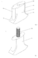
- the threaded portion 28 is formed as a extending in the vertical direction threaded pin with an external thread.
- the tightening element not shown, is correspondingly a nut for unscrewing on the threaded pin 28.
- the threaded pin 28 is preferably an integral body portion of a base body 6 of the securing element 1 and is mitgefertigt in its manufacture. It is not a separate part, but is formed as part of an example selective or adaptive production of the base body 6. Exemplary production methods are laser sintering or laser melting.
- FIG. 5 a third embodiment of the fuse element 1 according to the invention is shown.
- a threaded pin 28 is a separate part of a base body 6 of the securing element 1 and inserted with a portion in a receiving bore 50 of the base body 6.
- the receiving bore 50 has an internal thread and the threaded pin 28 is correspondingly screwed into the receiving bore 50.
- a securing element for a row of blades of a turbomachine wherein the blade row comprises a plurality of blades, which are used with their feet in a rotor-side anchoring groove and thereby held in the radial direction positively in the anchoring, with a base body having a front abutment surface and a rear contact surface for positive engagement with opposite groove surfaces, a front locking projection and a rear locking projection for engaging in opposite recesses of the anchoring groove, and a threaded portion for cooperation with a tightening element, wherein access to the threaded portion for the tightening element is locked on one side, and a turbomachine.
Landscapes
- Engineering & Computer Science (AREA)
- Mechanical Engineering (AREA)
- General Engineering & Computer Science (AREA)
- Turbine Rotor Nozzle Sealing (AREA)
- Structures Of Non-Positive Displacement Pumps (AREA)
Abstract
Description
- Die Erfindung betrifft ein Sicherungselement für eine Schaufelreihe einer Strömungsmaschine nach dem Oberbegriff des Patentanspruchs 1 und eine Strömungsmaschine.
- Ein bekanntes Bauprinzip von Schaufelreihen, insbesondere von Laufschaufelreihen, einer Strömungsmaschine wie ein Flugzeugtriebwerk, eine stationäre Gasturbine oder Dampfturbine sieht vor, die Schaufeln der jeweiligen Schaufelreihen mit ihren Füßen in eine rotorseitige Verankerungsnut einzusetzen. In radialer Richtung werden die Schaufeln durch ihre Füße formschlüssig in der Verankerungsnut gehalten. In Umfangsrichtung erfolgt eine Lagesicherung durch ein Sicherungselement, dass in die Verankerungsnut eingesetzt ist. Ein bekanntes Sicherungselement hat einen Grundkörper, der eine vordere Anlageflächen und eine hintere Anlagefläche zum Formschluss mit gegenüberliegenden Nutflächen aufweist, einen vorderen Verriegelungsvorsprung und einen hinteren Verriegelungsvorsprung zum Eingreifen in gegenüberliegende Ausnehmungen der Verankerungsnut, und einen Gewindebereich zum Zusammenwirken mit einem Anzugelement hat. Das Sicherungselement wird nach dem Einführen der Schaufeln in die Verankerungsnut eingesetzt, in seiner Umfangsposition verschoben und durch das Anzugelement in seine Sicherungslage überführt bzw. von unten gegen die Nutflächen gezogen. Dabei wird zwischen dem Sicherungselement ein plattenförmiges Brückenelement angeordnet, dass beim Anziehen des Anzugelements von oben gegen die Nutflächen gedrückt wird, woraufhin das Sicherungselement von unten gegen die Nutflächen gezogen wird. Ein derartiges Bauprinzip ist in dem Patent
US 7,708,529 B2 der Anmelderin als Stand der Technik gezeigt. Aus derUS 4,859,149 ist ebenfalls ein Sicherungselement bekannt, das mit einer Schraube und einem plattenartigen Brückenelement zusammenwirkt. Das Sicherungselement wird von einer Gewindebohrung durchsetzt, in die die Schraube eingedreht wird. Das Brückenelement ist zwischen dem Sicherungselement angeordnet und bewirkt in Kombination mit der Schraube ein Anheben bzw. Sichern des Sicherungselements an Nutflächen der Verankerungsnut. Es hat sich jedoch bei diesen Prinzipien gezeigt, dass das Sicherungselement konstruktionsbedingt mit seiner Innenseite radial nach außen verschraubt werden kann, wodurch die Verriegelungsvorsprünge nicht in die nutseitigen Ausnehmungen eingreifen und die Schaufeln umfangsmäßig nicht gesichert werden und desintegrieren können. In derUS 7,708,529 B2 ist des Weiteren eine Sicherung von Laufschaufeln in Umfangsrichtung dadurch realisiert, dass die Verankerungsnut zinnenartige Radialvorsprünge hat, die axial von Sicherungsstiften durchsetzt sind und hierdurch seitliche Anschläge für die Laufschaufeln bilden. - In der
CA 2829460 A1 und in derGB 2 156 908 A - Aus der
US 4,255,086 sind Sicherungselemente bekannt, die auf einen in einer Verankerungsnut eingesetzten Drahtring aufgefädelt werden. - Aufgabe der Erfindung ist es, ein Sicherungselement für eine Schaufelreihe einer Strömungsmaschine zu schaffen, bei dem eine Fehlmontage verhindert wird. Des Weiteren ist es Aufgabe der Erfindung, eine Strömungsmaschine mit einer erhöhten Zuverlässigkeit zu schaffen.
- Diese Aufgabe wird gelöst durch ein Sicherungselement mit den Merkmalen des Patentanspruchs 1 und durch eine Strömungsmaschine mit den Merkmalen des Patentanspruchs 10.
- Ein erfindungsgemäßes Sicherungselement für eine Schaufelreihe einer Strömungsmaschine, wobei die Schaufelreihe eine Vielzahl von Schaufeln umfasst, die mit ihren Füßen in einer rotorseitigen Verankerungsnut eingesetzt und hierdurch in radialer Richtung formschlüssig in der Verankerungsnut gehalten sind, hat einen Grundkörper, der eine vordere Anlageflächen und eine hintere Anlagefläche zum Formschluss mit gegenüberliegenden Nutflächen, einen vorderen Verriegelungsvorsprung und einen hinteren Verriegelungsvorsprung zum Eingreifen in gegenüberliegende Ausnehmungen der Verankerungsnut, und einen Gewindebereich zum Zusammenwirken mit einem Anzugelement aufweist. Erfindungsgemäß ist der Gewindebereich für das Anzugelement nur einseitig zugänglich.
- Durch die einseitige Zugänglichkeit des Gewindebereichs kann das Anzugelement nur von einer Seite auf den Gewindebereich aufgesetzt werden. Hierdurch wird eine Fehlmontage des Sicherungselements zuverlässig verhindert, da das Anzugelement nur in der richtigen Positionierung des Sicherungselementes innerhalb der Verankerungsnut mit dem Gewindebereich in Wirkeingriff bringbar ist. In einer Fehlpositionierung ist der Zugang zum Gewindebereich für das Anzugelement gesperrt. Das erfindungsgemäße Sicherungselement kann konstruktionsbedingt nicht mit seiner Innenseite bzw. seiner Unterseite nach außen verschraubt werden. Eine Änderung von Verschlussschaufeln zur Vermeidung einer Fehlmontage ist nicht notwendig.
- Bei einem Ausführungsbeispiel ist der Gewindebereich eine bodenseitig verschlossene Innengewindebohrung. Durch das Ausbilden einer Innengewindebohrung lässt sich auf bekannte Techniken zurückgreifen, wobei durch den bodenseitigen Verschluss ein zuverlässiges Verschließen erfolgt.
- Bevorzugterweise ist die Innengewindebohrung eine Durchgangsbohrung und bodenseitig durch ein außenseitiges Verschlusselement, beispielsweise ein Plattenelement, am Grundkörper verschlossen. Die Innengewindebohrung lässt sich aufgrund ihres durchgehenden Charakters technisch einfach einbringen und der nachträgliche bodenseitige Verschluss, d.h. nach der Ausbildung der Innengewindebohrung, ermöglicht ein technisch einfaches Verschließen. Beispielsweise wird das außenseitige Verschlusselement durch Stoffschluss wie Löten oder Schweißen an dem Grundkörper angebracht. Diese Variante ermöglicht die Nachrüstung von bestehenden Sicherungselementen mit den Verschlusselementen, so dass auch bestehende Sicherungselemente gegen Fehlmontagen geschützt werden können.
- Alternativ ist die Innengewindebohrung eine Durchgangsbohrung und bodenseitig durch ein innenseitiges Verschlusselement verschlossen. Das innenseitige Verschlusselement ist beispielsweise ein Stopfenelement, das mit einem Abschnitt in die Innengewindebohrung hineinragt. Diese ermöglicht eine kraft- und formschlüssige Montage an dem Grundkörper.
- Die Innengewindebohrung kann auch eine Sacklochbohrung sein. Durch diese Maßnahme wird die Teileanzahl des Sicherungselements reduziert, da separate Verschlusselemente zum einseitigen Verschließen des Gewindebereichs entfallen. Zudem wird durch den Wegfall der Montage der Verschlusselemente die Montagezeit verkürzt.
- Bei einem Ausführungsbeispiel ist der Gewindebereich ein sich von dem Grundkörper erstreckender Gewindestift. Der Gewindestift gibt die Einbaulage eindeutig vor, so dass ein falsches Einsetzen des Sicherungselements in die Verankerungsnut wirkungsvoll verhindert wird. Als Anzugelement dient bei dieser Variante eine Mutter. Als Zugangssperre für das Anzugelement wirkt dabei der Grundkörper per se.
- Der Gewindestift kann in eine Aufnahmebohrung des Grundkörpers eingesetzt sein. Durch diese Maßnahme werden der Grundkörper und der Gewindestift einzeln hergestellt, was eine einfache Herstellung ermöglicht. Die Verbindung des Gewindestiftes mit dem Grundkörper kann beispielsweise mittels Eindrehen in die Aufnahmebohrung, eine verdrehsichere Rastverbindung und dergleichen erfolgen.
- Der Gewindestift kann auch stoffschlüssig an dem Grundkörper angebunden sein. Ein Stoffschluss ist eine zuverlässige und technisch beherrschbare Verbindung und kann bspw. durch Schweißen und Löten erzielt werden. Selbstverständlich kann der Gewindestift auch in die Aufnahmebohrung eingesetzt und umfangsseitig bspw. im Mündungsbereich der Aufnahmebohrung mit dem Grundkörper verschweißt sein.
- Alternativ ist der Gewindestift ein integraler Körperabschnitt des Grundkörpers ist. Durch diese Maßnahme werden die Teileanzahl und die Montage des Sicherungselements reduziert. Beispielsweise erfolgt die Herstellung des Sicherungselements gemäß einem selektiven bzw. adaptiven Herstellungsverfahren wie Lasersintern, Laserschmelzen und dergleichen. Derartige Herstellungsverfahren ermöglichen insbesondere auch eine flexible Formgestaltung des Grundkörpers und des Gewindestiftes bzw. Gewindezapfens.
- Eine bevorzugte Strömungsmaschine hat eine Schaufelreihe, deren Schaufeln in Umfangsrichtung mittels eines Sicherungselements nach einem der vorhergehenden Patentansprüche gesichert sind. Bei einer derartigen Schaufelreihe ist eine Fehlmontage des Sicherungselements verhindert, so dass sich die bevorzugte Strömungsmaschine durch eine erhöhte Zuverlässigkeit im Vergleich zu bekannten Strömungsmaschinen ohne das erfindungsgemäße Sicherungselement auszeichnet.
- Sonstige vorteilhafte Ausführungsbeispiele der Erfindung sind Gegenstand weiterer Unteransprüche.
- Im Folgenden werden bevorzugte Ausführungsbeispiele der Erfindung anhand von schematischen Darstellungen näher erläutert. Es zeigen:
- Figur 1
- einen Längsschnitt durch ein erstes Ausführungsbeispiel eines erfindungsgemäßen Sicherungselements eingesetzt in einer rotorseitigen Verankerungsnut einer Strömungsmaschine,
- Figur 2
- eine Unteransicht des ersten Ausführungsbeispiels,
- Figur 3
- eine perspektive Draufsicht auf das erste Ausführungsbeispiel,
- Figur 4
- eine perspektive Darstellung eines zweiten Ausführungsbeispiels des erfindungsgemäßen Sicherungselements, und
- Figur 5
- eine perspektive Darstellung eines dritten Ausführungsbeispiels des erfindungsgemäßen Sicherungselements.
- In
Fig. 1 ist eine Schnittdarstellung eines ersten Ausführungsbeispiels eines erfindungsgemäßen Sicherungselements 1 einer Strömungsmaschine einer Schaufelreihe gezeigt. - Mit Bezug zur
Fig. 1 wird die Strömungsmaschine in Richtung ihrer Maschinenlängsachse, also in axialer Richtung, von einem Primärstrom von links nach rechts durchströmt. Angaben wie "hinterer" und "vorderer" beziehen sich auf die Strömungsrichtung des Primärstroms, Angaben wie "radial" auf die Rotor- bzw. Maschinenlängsachse der Strömungsmaschine. Die Strömungsmaschine ist beispielsweise eine Gasturbine und insbesondere ein Flugtriebwerk. - Die Schaufelreihe besteht aus einer Vielzahl von in Umfangsrichtung der Strömungsmaschine nebeneinander angeordneten Laufschaufeln 2. Die Laufschaufeln 2 sind jeweils mit ihrem vom Sicherungselement 1 verdeckten Fuß bzw. Fußabschnitt in einer rotorseitigen und umfangsseitigen Verankerungsnut 4 aufgenommen.
- Das Sicherungselement 1 ist in der Verankerungsnut 4 der Strömungsmaschine eingesetzt und wirkt als Umfangssicherung für die Laufschaufeln 2. Eine radiale Sicherung der Laufschaufeln 2 erfolgt formschlüssig durch ihre Füße in der Verankerungsnut 4. Das Sicherungselement 1 hat einen im weitesten Sinn quaderartigen, metallischen Grundkörper 6 und ist mittels einer vorderen Anlagefläche 8 und einer hinteren Anlagefläche 10 des Grundkörpers 6 mit gegenüberliegenden Nutflächen 12, 14 der Verankerungsnut 4 verspannt. Es taucht mit einem vorderen Verriegelungsvorsprung 16 und mit einem hinteren Verriegelungsvorsprung 18 in gegenüberliegende Ausnehmungen 20, 22 der Verankerungsnut 4 ein. Die Verspannung erfolgt mittels einer eines Anzugelements 24, das hier eine Schraube, und mittels eines plattenförmigen Brückenelements 26. Die Schraube 24 ist in einen Gewindebereich 28 des Grundkörpers 6 eingeschraubt und stützt sich mit ihrem Schraubenkopf 38 auf dem Brückenelement 26 ab, das randseitig auf zu den Nutflächen 12, 14 entgegengesetzten Stützflächen 30, 32 der Verankerungsnut 4 aufliegt. Die Schraube 24 ist beispielweise eine Innensechskantschraube, die durch ein stirnseitig in den Schraubenkopf 38 eingreifendes Werkzeug betätigt wird. Beim Anziehen der Schraube 24 bzw. des Anzugelements wird das Brückenelement 26 von oben gegen die Stützflächen 30, 32 gepresst und hierdurch der Grundkörper 6 von unten gegen die Nutflächen 12, 14 gezogen, wodurch es neben seiner Fixierung in seiner Sicherungslage auch vom Nutgrund 34 abgehoben wird. Zum schaftseitigen Durchführen der Schraube 24 hat das Brückenelement 26 eine entsprechende Durchgangsbohrung 36. Zur Aufnahme des Schraubenkopfes 38 haben die sogenannten Verschlussschaufeln im Bereich ihrer radial inneren Plattformen 40 entsprechende Ausnehmungen 42. Um Turbulenzen im Bereich des Primärstroms zu vermeiden, ist der Schraubenkopf 38 im eingeschraubten Zustand unterhalb einer ringraumseitigen Plattformfläche 44 angeordnet.
- Der Gewindebereich 28 ist bei diesem Ausführungsbeispiel eine den Grundkörper 6 in Hochrichtung durchsetzende Innengewindebohrung. Die Hochrichtung ist in
Figur 1 durch die gestrichelte vertikale Linie angedeutet. Um eine Fehlmontage des Sicherungselements 1 zu verhindern, ist der Gewindebereich 28 bodenseitig über ein plattenförmiges Verschlusselement 46 außenseitig verschlossen. Somit ist der Gewindebereich 28 bzw. die Innengewindebohrung für die Schraube 24 nur von einer Seite zugänglich. - Wie in
Figur 2 durch vier Kreuze 48 angedeutet, wird das äußere Verschlusselement 46 separat von dem Grundkörper 6 hergestellt und nachträglich mit diesem verbunden. Das Verschlusselement 46 ist wie der Grundkörper 6 metallisch. Die Anbindung erfolgt beispielsweise mittels Stoffschluss, bevorzugterweise mittels Punktschweißens oder Lötens. - In
Figur 3 ist eine perspektive Draufsicht auf das erste Ausführungsbeispiels des erfindungsgemäßen Sicherungselements 1 gezeigt. In dieser sind der Grundkörper 6, die zueinander entgegengesetzten Verriegelungsvorsprünge 16, 18, die zueinander entgegengesetzten Anlagenflächen 8, 10 und die Innengewindebohrung 28 deutlich zu erkennen. - In
Figur 4 ist ein zweites Ausführungsbeispiel des erfindungsgemäßen Sicherungselements 1 gezeigt. Im Unterschied zum ersten Ausführungsbeispiel nach denFiguren 1 bis 3 wirkt bei diesem Ausführungsbeispiel der Grundkörper 6 selbst als einseitige Zugangssperre für ein Anzugelement und somit als Verschlusselement 46. Hierzu ist der Gewindebereich 28 als ein sich in Hochrichtung erstreckender Gewindestift mit einem Außengewinde ausgebildet. Das nicht gezeigte Anzugelement ist entsprechend eine Mutter zum Aufdrehen auf den Gewindestift 28. Der Gewindestift 28 ist bevorzugterweise ein integraler Körperabschnitt eines Grundkörpers 6 des Sicherungselements 1 und wird bei dessen Herstellung mitgefertigt. Er ist kein separates Teil, sondern wird im Rahmen einer beispielweise selektiven bzw. adaptiven Herstellung des Grundkörpers 6 ausgebildet. Beispielhafte Herstellungsverfahren sind Lasersintern oder Laserschmelzen. - In
Figur 5 ist ein drittes Ausführungsbeispiel des erfindungsgemäßen Sicherungselements 1 gezeigt. Im Unterschied zum zweiten Ausführungsbeispiel nach denFigur 4 ist ein Gewindestift 28 ein separates Teil eines Grundkörpers 6 des Sicherungselements 1 und mit einem Abschnitt in eine Aufnahmebohrung 50 des Grundkörpers 6 eingesetzt. Beispielsweise hat die Aufnahmebohrung 50 ein Innengewinde und der Gewindestift 28 ist entsprechend in die Aufnahmebohrung 50 eingedreht. - Offenbart ist ein Sicherungselement für eine Schaufelreihe einer Strömungsmaschine, wobei die Schaufelreihe eine Vielzahl von Schaufeln umfasst, die mit ihren Füßen in einer rotorseitigen Verankerungsnut eingesetzt und hierdurch in radialer Richtung formschlüssig in der Verankerungsnut gehalten sind, mit einem Grundkörper, der eine vordere Anlagefläche und eine hintere Anlagefläche zum Formschluss mit gegenüberliegenden Nutflächen, einen vorderen Verriegelungsvorsprung und einen hinteren Verriegelungsvorsprung zum Eingreifen in gegenüberliegende Ausnehmungen der Verankerungsnut, und einen Gewindebereich zum Zusammenwirken mit einem Anzugelement hat, wobei ein Zugang zum Gewindebereich für das Anzugelement einseitig gesperrt ist, sowie eine Strömungsmaschine.
-
- 1
- Sicherungselement
- 2
- Leitschaufel
- 4
- Verankerungsnut
- 6
- Grundkörper
- 8
- vordere Anlagefläche
- 10
- hintere Anlagefläche
- 12
- vordere Nutfläche
- 14
- hintere Nutfläche
- 16
- vorderer Verriegelungsvorsprung
- 18
- hinterer Verriegelungsvorsprung
- 20
- Ausnehmung
- 22
- Ausnehmung
- 24
- Anzugelement / Schraube / Mutter
- 26
- Brückenelement
- 28
- Gewindebereich / Innengewindebohrung / Gewindestift
- 30
- Stützfläche
- 32
- Stützfläche
- 34
- Nutgrund
- 36
- Durchgangsbohrung
- 38
- Schraubenkopf
- 40
- Plattform
- 42
- Ausnehmung
- 44
- Plattformfläche
- 46
- Verschlusselement
- 48
- Kreuze
- 50
- Aufnahmebohrung
Claims (10)
- Sicherungselement (1) für eine Schaufelreihe einer Strömungsmaschine, wobei die Schaufelreihe eine Vielzahl von Schaufeln (2) umfasst, die mit ihren Füßen in einer rotorseitigen Verankerungsnut (4) eingesetzt und hierdurch in radialer Richtung formschlüssig in der Verankerungsnut gehalten sind, mit einem Grundkörper (6), der eine vordere Anlagefläche (8) und eine hintere Anlagefläche (10) zum Formschluss mit gegenüberliegenden Nutflächen (12, 14), einen vorderen Verriegelungsvorsprung (16) und einen hinteren Verriegelungsvorsprung (18) zum Eingreifen in gegenüberliegende Ausnehmungen (20, 22) der Verankerungsnut (4), und einen Gewindebereich (28) zum Zusammenwirken mit einem Anzugelement (24) hat, dadurch gekennzeichnet, dass der Gewindebereich (28) für das Anzugelement (24) nur einseitig zugänglich ist.
- Sicherungselement nach Patentanspruch 1, wobei der Gewindebereich (28) eine bodenseitig verschlossene Innengewindebohrung ist.
- Sicherungselement nach Patentanspruch 2, wobei die Innengewindebohrung (28) eine Durchgangsbohrung ist und bodenseitig durch ein außenseitiges Verschlusselement (46) verschlossen ist.
- Sicherungselement nach Patentanspruch 2, wobei die Innengewindebohrung (28) eine Durchgangsbohrung ist und bodenseitig durch ein innenseitiges Verschlusselement (46) verschlossen ist.
- Sicherungselement nach Patentanspruch 2, wobei die Innengewindebohrung (28) eine Sacklochbohrung ist.
- Sicherungselement nach Patentanspruch 1, wobei der Gewindebereich (28) ein sich von dem Grundkörper (6) erstreckender Gewindestift ist.
- Sicherungselement nach Patentanspruch 6, wobei der Gewindestift (28) in eine Aufnahmebohrung des Grundkörpers (6) eingesetzt ist.
- Sicherungselement nach Patentanspruch 6 oder 7, wobei der Gewindestift (28) stoffschlüssig an dem Grundkörper (6) angebunden ist.
- Sicherungselement nach Patentanspruch 6, wobei der Gewindestift (28) ein integraler Körperabschnitt des Grundkörpers (6) ist.
- Strömungsmaschine mit einer Schaufelreihe, deren Schaufeln (2) in Umfangsrichtung mittels eines Sicherungselements (1) nach einem der vorhergehenden Patentansprüche gesichert sind.
Applications Claiming Priority (1)
| Application Number | Priority Date | Filing Date | Title |
|---|---|---|---|
| DE102015203290.6A DE102015203290A1 (de) | 2015-02-24 | 2015-02-24 | Sicherungselement und Strömungsmaschine |
Publications (2)
| Publication Number | Publication Date |
|---|---|
| EP3061917A1 true EP3061917A1 (de) | 2016-08-31 |
| EP3061917B1 EP3061917B1 (de) | 2018-06-06 |
Family
ID=55129741
Family Applications (1)
| Application Number | Title | Priority Date | Filing Date |
|---|---|---|---|
| EP16151258.7A Not-in-force EP3061917B1 (de) | 2015-02-24 | 2016-01-14 | Sicherungselement und strömungsmaschine |
Country Status (3)
| Country | Link |
|---|---|
| US (1) | US10352178B2 (de) |
| EP (1) | EP3061917B1 (de) |
| DE (1) | DE102015203290A1 (de) |
Families Citing this family (4)
| Publication number | Priority date | Publication date | Assignee | Title |
|---|---|---|---|---|
| KR102095033B1 (ko) * | 2017-05-30 | 2020-03-30 | 두산중공업 주식회사 | 베인 링 조립체 및 이를 포함하는 압축기, 가스터빈 |
| DE102019111211A1 (de) * | 2019-04-30 | 2020-11-05 | Rolls-Royce Deutschland Ltd & Co Kg | Vorrichtung zur Einstellung eines Wuchtzustandes eines rotierenden Teils eines Gasturbinentriebwerkes, ein Wuchtkörper und ein Gasturbinentriebwerk für ein Luftfahrzeug |
| CN115217529A (zh) * | 2021-04-20 | 2022-10-21 | 中国航发商用航空发动机有限责任公司 | 转子叶片的锁紧装置 |
| US12221899B2 (en) * | 2023-06-15 | 2025-02-11 | General Electric Company | Methods and apparatuses for blade locking |
Citations (6)
| Publication number | Priority date | Publication date | Assignee | Title |
|---|---|---|---|---|
| US4255086A (en) | 1979-06-27 | 1981-03-10 | Pratt & Whitney Aircraft Of Canada Limited | Locking device for blade mounting |
| GB2156908A (en) | 1984-03-30 | 1985-10-16 | Rolls Royce | Bladed rotor assembly for gas turbine engine |
| US4859149A (en) | 1989-03-10 | 1989-08-22 | General Motors Corporation | Blade locking system |
| US7708529B2 (en) | 2004-10-20 | 2010-05-04 | Mtu Aero Engines Gmbh | Rotor of a turbo engine, e.g., a gas turbine rotor |
| US20120251329A1 (en) * | 2011-03-17 | 2012-10-04 | Mitsubishi Heavy Industries, Ltd. | Rotor structure |
| CA2829460A1 (en) | 2012-10-12 | 2014-04-12 | Techspace Aero S.A. | Drum blade lock in a circumferential rotor groove |
Family Cites Families (7)
| Publication number | Priority date | Publication date | Assignee | Title |
|---|---|---|---|---|
| GB2171150B (en) * | 1985-02-12 | 1989-07-26 | Rolls Royce Plc | Bladed rotor assembly for a turbomachine |
| GB0102757D0 (en) * | 2001-02-03 | 2001-03-21 | Rolls Royce Plc | Locking device |
| FR2832455B1 (fr) * | 2001-11-22 | 2004-04-02 | Snecma Moteurs | Dispositif de blocage des aubes dans une rainure d'un disque |
| ITMI20012783A1 (it) * | 2001-12-21 | 2003-06-21 | Nuovo Pignone Spa | Sistema di connessione e bloccaggio di pale rotoriche di un compressore assiale |
| US7435055B2 (en) * | 2005-03-29 | 2008-10-14 | Siemens Power Generation, Inc. | Locking spacer assembly for a turbine engine |
| US8523529B2 (en) * | 2009-11-11 | 2013-09-03 | General Electric Company | Locking spacer assembly for a circumferential entry airfoil attachment system |
| US8757981B2 (en) * | 2011-04-28 | 2014-06-24 | Siemens Aktiengesellschaft | Locking spacer assembly for a turbine engine |
-
2015
- 2015-02-24 DE DE102015203290.6A patent/DE102015203290A1/de not_active Ceased
-
2016
- 2016-01-14 EP EP16151258.7A patent/EP3061917B1/de not_active Not-in-force
- 2016-02-15 US US15/043,643 patent/US10352178B2/en not_active Expired - Fee Related
Patent Citations (6)
| Publication number | Priority date | Publication date | Assignee | Title |
|---|---|---|---|---|
| US4255086A (en) | 1979-06-27 | 1981-03-10 | Pratt & Whitney Aircraft Of Canada Limited | Locking device for blade mounting |
| GB2156908A (en) | 1984-03-30 | 1985-10-16 | Rolls Royce | Bladed rotor assembly for gas turbine engine |
| US4859149A (en) | 1989-03-10 | 1989-08-22 | General Motors Corporation | Blade locking system |
| US7708529B2 (en) | 2004-10-20 | 2010-05-04 | Mtu Aero Engines Gmbh | Rotor of a turbo engine, e.g., a gas turbine rotor |
| US20120251329A1 (en) * | 2011-03-17 | 2012-10-04 | Mitsubishi Heavy Industries, Ltd. | Rotor structure |
| CA2829460A1 (en) | 2012-10-12 | 2014-04-12 | Techspace Aero S.A. | Drum blade lock in a circumferential rotor groove |
Also Published As
| Publication number | Publication date |
|---|---|
| US10352178B2 (en) | 2019-07-16 |
| DE102015203290A1 (de) | 2016-09-29 |
| US20160245101A1 (en) | 2016-08-25 |
| EP3061917B1 (de) | 2018-06-06 |
Similar Documents
| Publication | Publication Date | Title |
|---|---|---|
| EP3061917B1 (de) | Sicherungselement und strömungsmaschine | |
| DE1289374B (de) | Rohrverbindungsstueck fuer Hochdruckleitungen | |
| DE112008000447T5 (de) | Sicherheitsventil | |
| DE112016005003B4 (de) | Dampfventil und dampfturbinensystem | |
| EP2730843A1 (de) | Brennkammerschindel einer Gasturbine | |
| DE102014101416A1 (de) | Ventilvorrichtung für einen hydraulischen Türschließer | |
| WO2005049980A1 (de) | Leichtbauventil | |
| DE3901586A1 (de) | Zusammengesetzte berstscheiben-vorrichtung und berstteil dafuer | |
| EP3353455B1 (de) | Rückschlagventil | |
| DE102011005405A1 (de) | Befestigungsanordnung | |
| EP1584793A2 (de) | Turbinenschaufelarretiervorrichtung | |
| DE102008060705A1 (de) | Horizontal geteiltes Strömungsmaschinengehäuse | |
| EP3312388B1 (de) | Rotorteil, zugehörigeverdichter, turbine und herstellungsverfahren | |
| DE102008019852A1 (de) | Befestigungsanordnung für mehrere Ringkabelschuhe an einem Schweißbolzen | |
| EP2918775A1 (de) | Verfahren zum Verschließen einer Öffnung einer Turbinenschaufel und dazu geeigneter Stopfen | |
| EP2826955A1 (de) | Gegossene Turbinenschaufel mit einer durch einen Stopfen verschlossenen Öffnung und Verfahren zum Verschließen einer Öffnung einer gegossenen Turbinenschaufel | |
| DE102004016244B4 (de) | Rotor für eine Turbomaschine | |
| EP2873808B1 (de) | Schaufel-Scheiben-Verbund, Verfahren und Strömungsmaschine | |
| EP3015655A1 (de) | Radscheibenanordnung mit Dichtblechen | |
| DE112016004081T5 (de) | Treibstoffeinfüllstutzenvorrichtung | |
| EP1862638B1 (de) | Verfahren zum Reparieren des Rotors einer Gasturbine sowie Rotor einer Gasturbine | |
| EP4130441A1 (de) | Verbindungseinrichtung einer verstellbaren schaufel einer gasturbine und gasturbine | |
| EP1306522A1 (de) | Sicherungsvorrichtung für Laufschaufeln axial durchströmter Turbomaschinen | |
| EP3240965B1 (de) | Eckventil | |
| DE102017108270A1 (de) | Dichtungskassette für einen Injektor einer Verbrennungskraftmaschine und Injektoranordnung für eine Verbrennungskraftmaschine |
Legal Events
| Date | Code | Title | Description |
|---|---|---|---|
| PUAI | Public reference made under article 153(3) epc to a published international application that has entered the european phase |
Free format text: ORIGINAL CODE: 0009012 |
|
| AK | Designated contracting states |
Kind code of ref document: A1 Designated state(s): AL AT BE BG CH CY CZ DE DK EE ES FI FR GB GR HR HU IE IS IT LI LT LU LV MC MK MT NL NO PL PT RO RS SE SI SK SM TR |
|
| AX | Request for extension of the european patent |
Extension state: BA ME |
|
| STAA | Information on the status of an ep patent application or granted ep patent |
Free format text: STATUS: REQUEST FOR EXAMINATION WAS MADE |
|
| 17P | Request for examination filed |
Effective date: 20170216 |
|
| RBV | Designated contracting states (corrected) |
Designated state(s): AL AT BE BG CH CY CZ DE DK EE ES FI FR GB GR HR HU IE IS IT LI LT LU LV MC MK MT NL NO PL PT RO RS SE SI SK SM TR |
|
| RIC1 | Information provided on ipc code assigned before grant |
Ipc: F01D 5/30 20060101AFI20180208BHEP Ipc: F01D 5/32 20060101ALI20180208BHEP |
|
| GRAP | Despatch of communication of intention to grant a patent |
Free format text: ORIGINAL CODE: EPIDOSNIGR1 |
|
| STAA | Information on the status of an ep patent application or granted ep patent |
Free format text: STATUS: GRANT OF PATENT IS INTENDED |
|
| INTG | Intention to grant announced |
Effective date: 20180319 |
|
| GRAS | Grant fee paid |
Free format text: ORIGINAL CODE: EPIDOSNIGR3 |
|
| GRAA | (expected) grant |
Free format text: ORIGINAL CODE: 0009210 |
|
| STAA | Information on the status of an ep patent application or granted ep patent |
Free format text: STATUS: THE PATENT HAS BEEN GRANTED |
|
| AK | Designated contracting states |
Kind code of ref document: B1 Designated state(s): AL AT BE BG CH CY CZ DE DK EE ES FI FR GB GR HR HU IE IS IT LI LT LU LV MC MK MT NL NO PL PT RO RS SE SI SK SM TR |
|
| REG | Reference to a national code |
Ref country code: GB Ref legal event code: FG4D Free format text: NOT ENGLISH |
|
| REG | Reference to a national code |
Ref country code: CH Ref legal event code: EP Ref country code: AT Ref legal event code: REF Ref document number: 1006310 Country of ref document: AT Kind code of ref document: T Effective date: 20180615 |
|
| REG | Reference to a national code |
Ref country code: IE Ref legal event code: FG4D Free format text: LANGUAGE OF EP DOCUMENT: GERMAN |
|
| REG | Reference to a national code |
Ref country code: DE Ref legal event code: R096 Ref document number: 502016001128 Country of ref document: DE |
|
| REG | Reference to a national code |
Ref country code: NL Ref legal event code: MP Effective date: 20180606 |
|
| REG | Reference to a national code |
Ref country code: LT Ref legal event code: MG4D |
|
| PG25 | Lapsed in a contracting state [announced via postgrant information from national office to epo] |
Ref country code: NO Free format text: LAPSE BECAUSE OF FAILURE TO SUBMIT A TRANSLATION OF THE DESCRIPTION OR TO PAY THE FEE WITHIN THE PRESCRIBED TIME-LIMIT Effective date: 20180906 Ref country code: CY Free format text: LAPSE BECAUSE OF FAILURE TO SUBMIT A TRANSLATION OF THE DESCRIPTION OR TO PAY THE FEE WITHIN THE PRESCRIBED TIME-LIMIT Effective date: 20180606 Ref country code: LT Free format text: LAPSE BECAUSE OF FAILURE TO SUBMIT A TRANSLATION OF THE DESCRIPTION OR TO PAY THE FEE WITHIN THE PRESCRIBED TIME-LIMIT Effective date: 20180606 Ref country code: ES Free format text: LAPSE BECAUSE OF FAILURE TO SUBMIT A TRANSLATION OF THE DESCRIPTION OR TO PAY THE FEE WITHIN THE PRESCRIBED TIME-LIMIT Effective date: 20180606 Ref country code: BG Free format text: LAPSE BECAUSE OF FAILURE TO SUBMIT A TRANSLATION OF THE DESCRIPTION OR TO PAY THE FEE WITHIN THE PRESCRIBED TIME-LIMIT Effective date: 20180906 Ref country code: SE Free format text: LAPSE BECAUSE OF FAILURE TO SUBMIT A TRANSLATION OF THE DESCRIPTION OR TO PAY THE FEE WITHIN THE PRESCRIBED TIME-LIMIT Effective date: 20180606 Ref country code: FI Free format text: LAPSE BECAUSE OF FAILURE TO SUBMIT A TRANSLATION OF THE DESCRIPTION OR TO PAY THE FEE WITHIN THE PRESCRIBED TIME-LIMIT Effective date: 20180606 |
|
| PG25 | Lapsed in a contracting state [announced via postgrant information from national office to epo] |
Ref country code: LV Free format text: LAPSE BECAUSE OF FAILURE TO SUBMIT A TRANSLATION OF THE DESCRIPTION OR TO PAY THE FEE WITHIN THE PRESCRIBED TIME-LIMIT Effective date: 20180606 Ref country code: RS Free format text: LAPSE BECAUSE OF FAILURE TO SUBMIT A TRANSLATION OF THE DESCRIPTION OR TO PAY THE FEE WITHIN THE PRESCRIBED TIME-LIMIT Effective date: 20180606 Ref country code: HR Free format text: LAPSE BECAUSE OF FAILURE TO SUBMIT A TRANSLATION OF THE DESCRIPTION OR TO PAY THE FEE WITHIN THE PRESCRIBED TIME-LIMIT Effective date: 20180606 Ref country code: GR Free format text: LAPSE BECAUSE OF FAILURE TO SUBMIT A TRANSLATION OF THE DESCRIPTION OR TO PAY THE FEE WITHIN THE PRESCRIBED TIME-LIMIT Effective date: 20180907 |
|
| PG25 | Lapsed in a contracting state [announced via postgrant information from national office to epo] |
Ref country code: NL Free format text: LAPSE BECAUSE OF FAILURE TO SUBMIT A TRANSLATION OF THE DESCRIPTION OR TO PAY THE FEE WITHIN THE PRESCRIBED TIME-LIMIT Effective date: 20180606 |
|
| PG25 | Lapsed in a contracting state [announced via postgrant information from national office to epo] |
Ref country code: IS Free format text: LAPSE BECAUSE OF FAILURE TO SUBMIT A TRANSLATION OF THE DESCRIPTION OR TO PAY THE FEE WITHIN THE PRESCRIBED TIME-LIMIT Effective date: 20181006 Ref country code: PL Free format text: LAPSE BECAUSE OF FAILURE TO SUBMIT A TRANSLATION OF THE DESCRIPTION OR TO PAY THE FEE WITHIN THE PRESCRIBED TIME-LIMIT Effective date: 20180606 Ref country code: SK Free format text: LAPSE BECAUSE OF FAILURE TO SUBMIT A TRANSLATION OF THE DESCRIPTION OR TO PAY THE FEE WITHIN THE PRESCRIBED TIME-LIMIT Effective date: 20180606 Ref country code: EE Free format text: LAPSE BECAUSE OF FAILURE TO SUBMIT A TRANSLATION OF THE DESCRIPTION OR TO PAY THE FEE WITHIN THE PRESCRIBED TIME-LIMIT Effective date: 20180606 Ref country code: CZ Free format text: LAPSE BECAUSE OF FAILURE TO SUBMIT A TRANSLATION OF THE DESCRIPTION OR TO PAY THE FEE WITHIN THE PRESCRIBED TIME-LIMIT Effective date: 20180606 Ref country code: RO Free format text: LAPSE BECAUSE OF FAILURE TO SUBMIT A TRANSLATION OF THE DESCRIPTION OR TO PAY THE FEE WITHIN THE PRESCRIBED TIME-LIMIT Effective date: 20180606 |
|
| PG25 | Lapsed in a contracting state [announced via postgrant information from national office to epo] |
Ref country code: IT Free format text: LAPSE BECAUSE OF FAILURE TO SUBMIT A TRANSLATION OF THE DESCRIPTION OR TO PAY THE FEE WITHIN THE PRESCRIBED TIME-LIMIT Effective date: 20180606 Ref country code: SM Free format text: LAPSE BECAUSE OF FAILURE TO SUBMIT A TRANSLATION OF THE DESCRIPTION OR TO PAY THE FEE WITHIN THE PRESCRIBED TIME-LIMIT Effective date: 20180606 |
|
| REG | Reference to a national code |
Ref country code: DE Ref legal event code: R097 Ref document number: 502016001128 Country of ref document: DE |
|
| PLBE | No opposition filed within time limit |
Free format text: ORIGINAL CODE: 0009261 |
|
| STAA | Information on the status of an ep patent application or granted ep patent |
Free format text: STATUS: NO OPPOSITION FILED WITHIN TIME LIMIT |
|
| 26N | No opposition filed |
Effective date: 20190307 |
|
| PG25 | Lapsed in a contracting state [announced via postgrant information from national office to epo] |
Ref country code: SI Free format text: LAPSE BECAUSE OF FAILURE TO SUBMIT A TRANSLATION OF THE DESCRIPTION OR TO PAY THE FEE WITHIN THE PRESCRIBED TIME-LIMIT Effective date: 20180606 Ref country code: DK Free format text: LAPSE BECAUSE OF FAILURE TO SUBMIT A TRANSLATION OF THE DESCRIPTION OR TO PAY THE FEE WITHIN THE PRESCRIBED TIME-LIMIT Effective date: 20180606 |
|
| PG25 | Lapsed in a contracting state [announced via postgrant information from national office to epo] |
Ref country code: MC Free format text: LAPSE BECAUSE OF FAILURE TO SUBMIT A TRANSLATION OF THE DESCRIPTION OR TO PAY THE FEE WITHIN THE PRESCRIBED TIME-LIMIT Effective date: 20180606 |
|
| REG | Reference to a national code |
Ref country code: CH Ref legal event code: PL |
|
| PG25 | Lapsed in a contracting state [announced via postgrant information from national office to epo] |
Ref country code: LU Free format text: LAPSE BECAUSE OF NON-PAYMENT OF DUE FEES Effective date: 20190114 |
|
| REG | Reference to a national code |
Ref country code: BE Ref legal event code: MM Effective date: 20190131 |
|
| REG | Reference to a national code |
Ref country code: IE Ref legal event code: MM4A |
|
| PG25 | Lapsed in a contracting state [announced via postgrant information from national office to epo] |
Ref country code: AL Free format text: LAPSE BECAUSE OF FAILURE TO SUBMIT A TRANSLATION OF THE DESCRIPTION OR TO PAY THE FEE WITHIN THE PRESCRIBED TIME-LIMIT Effective date: 20180606 Ref country code: BE Free format text: LAPSE BECAUSE OF NON-PAYMENT OF DUE FEES Effective date: 20190131 |
|
| PG25 | Lapsed in a contracting state [announced via postgrant information from national office to epo] |
Ref country code: CH Free format text: LAPSE BECAUSE OF NON-PAYMENT OF DUE FEES Effective date: 20190131 Ref country code: LI Free format text: LAPSE BECAUSE OF NON-PAYMENT OF DUE FEES Effective date: 20190131 |
|
| PG25 | Lapsed in a contracting state [announced via postgrant information from national office to epo] |
Ref country code: IE Free format text: LAPSE BECAUSE OF NON-PAYMENT OF DUE FEES Effective date: 20190114 |
|
| PG25 | Lapsed in a contracting state [announced via postgrant information from national office to epo] |
Ref country code: TR Free format text: LAPSE BECAUSE OF FAILURE TO SUBMIT A TRANSLATION OF THE DESCRIPTION OR TO PAY THE FEE WITHIN THE PRESCRIBED TIME-LIMIT Effective date: 20180606 |
|
| PG25 | Lapsed in a contracting state [announced via postgrant information from national office to epo] |
Ref country code: PT Free format text: LAPSE BECAUSE OF FAILURE TO SUBMIT A TRANSLATION OF THE DESCRIPTION OR TO PAY THE FEE WITHIN THE PRESCRIBED TIME-LIMIT Effective date: 20181008 Ref country code: MT Free format text: LAPSE BECAUSE OF FAILURE TO SUBMIT A TRANSLATION OF THE DESCRIPTION OR TO PAY THE FEE WITHIN THE PRESCRIBED TIME-LIMIT Effective date: 20180606 |
|
| PG25 | Lapsed in a contracting state [announced via postgrant information from national office to epo] |
Ref country code: HU Free format text: LAPSE BECAUSE OF FAILURE TO SUBMIT A TRANSLATION OF THE DESCRIPTION OR TO PAY THE FEE WITHIN THE PRESCRIBED TIME-LIMIT; INVALID AB INITIO Effective date: 20160114 |
|
| REG | Reference to a national code |
Ref country code: AT Ref legal event code: MM01 Ref document number: 1006310 Country of ref document: AT Kind code of ref document: T Effective date: 20210114 |
|
| PG25 | Lapsed in a contracting state [announced via postgrant information from national office to epo] |
Ref country code: AT Free format text: LAPSE BECAUSE OF NON-PAYMENT OF DUE FEES Effective date: 20210114 |
|
| PGFP | Annual fee paid to national office [announced via postgrant information from national office to epo] |
Ref country code: GB Payment date: 20220125 Year of fee payment: 7 Ref country code: DE Payment date: 20220120 Year of fee payment: 7 |
|
| PGFP | Annual fee paid to national office [announced via postgrant information from national office to epo] |
Ref country code: FR Payment date: 20220120 Year of fee payment: 7 |
|
| PG25 | Lapsed in a contracting state [announced via postgrant information from national office to epo] |
Ref country code: MK Free format text: LAPSE BECAUSE OF FAILURE TO SUBMIT A TRANSLATION OF THE DESCRIPTION OR TO PAY THE FEE WITHIN THE PRESCRIBED TIME-LIMIT Effective date: 20180606 |
|
| REG | Reference to a national code |
Ref country code: DE Ref legal event code: R119 Ref document number: 502016001128 Country of ref document: DE |
|
| GBPC | Gb: european patent ceased through non-payment of renewal fee |
Effective date: 20230114 |
|
| PG25 | Lapsed in a contracting state [announced via postgrant information from national office to epo] |
Ref country code: GB Free format text: LAPSE BECAUSE OF NON-PAYMENT OF DUE FEES Effective date: 20230114 Ref country code: DE Free format text: LAPSE BECAUSE OF NON-PAYMENT OF DUE FEES Effective date: 20230801 |
|
| PG25 | Lapsed in a contracting state [announced via postgrant information from national office to epo] |
Ref country code: FR Free format text: LAPSE BECAUSE OF NON-PAYMENT OF DUE FEES Effective date: 20230131 |