EP3061890B1 - Durchführung zum Vergießen mit Beton - Google Patents
Durchführung zum Vergießen mit Beton Download PDFInfo
- Publication number
- EP3061890B1 EP3061890B1 EP15156782.3A EP15156782A EP3061890B1 EP 3061890 B1 EP3061890 B1 EP 3061890B1 EP 15156782 A EP15156782 A EP 15156782A EP 3061890 B1 EP3061890 B1 EP 3061890B1
- Authority
- EP
- European Patent Office
- Prior art keywords
- front plate
- double coupling
- duct
- formwork
- channels
- Prior art date
- Legal status (The legal status is an assumption and is not a legal conclusion. Google has not performed a legal analysis and makes no representation as to the accuracy of the status listed.)
- Active
Links
Images


Classifications
-
- F—MECHANICAL ENGINEERING; LIGHTING; HEATING; WEAPONS; BLASTING
- F16—ENGINEERING ELEMENTS AND UNITS; GENERAL MEASURES FOR PRODUCING AND MAINTAINING EFFECTIVE FUNCTIONING OF MACHINES OR INSTALLATIONS; THERMAL INSULATION IN GENERAL
- F16L—PIPES; JOINTS OR FITTINGS FOR PIPES; SUPPORTS FOR PIPES, CABLES OR PROTECTIVE TUBING; MEANS FOR THERMAL INSULATION IN GENERAL
- F16L5/00—Devices for use where pipes, cables or protective tubing pass through walls or partitions
- F16L5/02—Sealing
- F16L5/14—Sealing for double-walled or multi-channel pipes
-
- E—FIXED CONSTRUCTIONS
- E04—BUILDING
- E04G—SCAFFOLDING; FORMS; SHUTTERING; BUILDING IMPLEMENTS OR AIDS, OR THEIR USE; HANDLING BUILDING MATERIALS ON THE SITE; REPAIRING, BREAKING-UP OR OTHER WORK ON EXISTING BUILDINGS
- E04G15/00—Forms or shutterings for making openings, cavities, slits, or channels
- E04G15/06—Forms or shutterings for making openings, cavities, slits, or channels for cavities or channels in walls of floors, e.g. for making chimneys
- E04G15/061—Non-reusable forms
-
- F—MECHANICAL ENGINEERING; LIGHTING; HEATING; WEAPONS; BLASTING
- F16—ENGINEERING ELEMENTS AND UNITS; GENERAL MEASURES FOR PRODUCING AND MAINTAINING EFFECTIVE FUNCTIONING OF MACHINES OR INSTALLATIONS; THERMAL INSULATION IN GENERAL
- F16L—PIPES; JOINTS OR FITTINGS FOR PIPES; SUPPORTS FOR PIPES, CABLES OR PROTECTIVE TUBING; MEANS FOR THERMAL INSULATION IN GENERAL
- F16L5/00—Devices for use where pipes, cables or protective tubing pass through walls or partitions
- F16L5/02—Sealing
- F16L5/12—Sealing the pipe being cut in two pieces
-
- H—ELECTRICITY
- H02—GENERATION; CONVERSION OR DISTRIBUTION OF ELECTRIC POWER
- H02G—INSTALLATION OF ELECTRIC CABLES OR LINES, OR OF COMBINED OPTICAL AND ELECTRIC CABLES OR LINES
- H02G3/00—Installations of electric cables or lines or protective tubing therefor in or on buildings, equivalent structures or vehicles
- H02G3/22—Installations of cables or lines through walls, floors or ceilings, e.g. into buildings
Definitions
- the present invention relates to a bushing for installation in a wall or floor element by casting with concrete in a formwork and for subsequently mounting several lines.
- the EP 0 757 142 A1 relates to a passage for passing a plurality of installation conduits, wherein the passage breaks down a wall opening into a plurality of passage openings. Through each of the through holes then one of the installation cables can be performed.
- the US 3,731,448 A relates to a passage for setting in concrete.
- the implementation is provided at the end face with form-fitting elements and can be modularly assembled with other feedthroughs.
- the EP 0 246 219 A1 relates to a passage, which is composed of a flange with tube part and a casing and then embedded in concrete.
- the present invention has for its object to provide a passage for installation in a wall or floor element by casting with concrete, which shows improved performance characteristics.
- the invention is directed to a bushing for a plurality of lines, eg. At least 5, 10, 15, 20 or 25 lines (in the order of naming increasingly preferred); Possible upper limits can be, for example, at most 200, 150, 100 or 50 lines.
- a corresponding number of lines must be threaded through a respective passage opening in the elastomeric body or, in the case of a slotted and hinged to insert the lines of the elastomer body, this due to Variety of passage openings and thus slots become very unstable. Sometimes even two fitters may be required for the assembly, one of which holds the press seal and the other inserts or threads the wires.
- the present approach is now to actually use for the construction of a longer line of line sections used double clutch pieces in the implementation.
- the double clutch pieces are then together with the bushing in installed the wall or floor element. If a line is then to be "passed", a line piece with its line end is mounted on one side of the wall or floor element on the double coupling piece and also becomes a line piece with its line end on the same double coupling piece from the opposite side of the wall or floor element assembled.
- the double coupling piece connects the two pipe sections and the pipe is thus functionally passed through (through the passage or the wall or floor element).
- a "line” may, for example, also be a cable, such as a power or data cable.
- the conduit is a hollow tube, which, for example, may itself be media-conveying, for example in the case of a water pipe;
- the hollow tube can also lead in its interior another line, preferably a cable.
- the guided in the hollow tube cable is a fiber optic cable.
- double clutch piece means a part which provides exactly two connection points.
- the connection points per double coupling piece are of the same type, so that the double coupling piece is so symmetrical in design (for example, two male or two female connection points can be provided).
- the connection points of the double-clutch pieces are fittings, namely plug-in fittings.
- the double clutch piece at one end of a plug-in fitting and at its opposite end to another plug-in fitting; the one end of the line is then inserted from the one side of the wall or floor element ago in the one plug-in fitting, the other end of the line from the opposite side into the other plug-in fitting (at the opposite end of the same double-clutch piece).
- the plug-in fitting preferably has a pull-out safety device, for example in the form of a ring arranged obliquely in the insertion direction and toward the center axis of the line, which slides along the outside wall of the line during insertion of the line end, due to their oblique orientation during movement in opposite directions
- a pull-out safety device for example in the form of a ring arranged obliquely in the insertion direction and toward the center axis of the line, which slides along the outside wall of the line during insertion of the line end, due to their oblique orientation during movement in opposite directions
- the direction caught on the outer wall of the line and at least make it difficult to take off.
- sockets with releasable lock the mechanism for releasing the lock on the front side of the plug fitting is accessible.
- a sleeve can be actuated and pushed between the locking lamellae and the outer wall of the conduit via this end face so that the latter can be pulled out again.
- the use of such sockets with releasable locking can also be preferred in the present case, wherein then more preferably in the front panel access to the releasable locking is taken into account.
- This access can also be made generally via a separate channel, but is preferably taken into account in the channel with the double clutch piece.
- the double clutch pieces during assembly of the implementation especially when pouring concrete, advantageously held together and also protected piece.
- the plurality of double clutch pieces can thus be handled comparatively easily together and installed in the wall element. It must, for example, only the front panel are attached to the formwork, about so nailed or screwed, whereby at the same time the position of the double clutch pieces is fixed with respect to the then produced wall element.
- the double clutch pieces are held in the front plate while at the same time sealed against it;
- the front panel encloses the double clutch pieces so each sealing.
- the wall element in the course of "installation" of the implementation is preferably also only made yourself, so the wall element is poured while at the same time built the implementation.
- the front panel is "one-piece", so it can not be disassembled neatly into individual parts. In general, for example, this may also be a multi-component injection molded part; It may, for example, a stiffer plastic material form a system part for engagement with the formwork and a contrast softer plastic part provide the channels available.
- the one-piece front panel is monolithic, so it is in their interior free of material boundaries between different materials or materials of different production history.
- the front panel is a molded part, which is thus released in its shape from a mold (which is a mechanical post-processing in general, but not exclude, for example, a deburring).
- the front plate preferably has a side (with respect to the surface directions of the contact surface) on its side intended to rest on the formwork on the outside of the part of the front panel with the double clutch pieces protruding flange, which serves for attachment to the formwork.
- the front panel can therefore be attached to the formwork via the flange, for example with it nailed or screwed.
- Preferred is a completely circumferential flange. More preferably, a circumferential survey is provided on the intended to rest on the formwork side of the flange, which then finds on the formwork a corresponding circumferential system, preferably an approximately linear system. If the flange is attached to the formwork, this elevation is pressed with slightly increased pressure, which can help prevent the undesired entry of concrete.
- the front plate and the dual clutch pieces are multi-piece to each other, preferably, the dual clutch pieces are each inserted into their respective channel.
- the dual clutch pieces are each inserted into their respective channel.
- both the front plate to each of the double clutch pieces is multi-piece and these are also multi-piece with each other.
- a web seal is provided on the outside of the front panel, on an outer surface thereof which extends from the side of the front panel intended to rest against the formwork to the opposite side, preferably completely encircling (this refers to a circulation around the center axis of the lines).
- the web seal is spaced from the side of the front plate provided for the system on the formwork, that is to say offset inward, ie lies within the wall element after concreting; the concrete encloses the bridge seal.
- a plurality of such web seals are provided, for example at least two, and, for example, not more than five or four web seals; Particularly preferred are three web seals.
- the double clutch pieces are thus protected from both sides.
- mounting the implementation of the first front plate is applied to a formwork element and the opposite second front panel on a second formwork element opposite the first formwork element.
- the double clutch pieces are held together so well, and the implementation can be handled comparatively easy and positioned in the formwork.
- the number sequences are preferably applied to the front plate in such a way the first front plate the second number sequence is upside down, so the first number sequence is relevant, and in the second front panel, the first number sequence is upside down (and the second is relevant).
- the invention also relates to a wall element made of concrete with a presently disclosed implementation therein, which is thus poured into the wall element, that is incorporated in the course of its production. From each side of the wall element then one line end can be mounted per line. As far as generally per line from a line end, which is mounted from one side, and a line end, which is mounted from the opposite side, is mentioned, this of course refers to the ends of sections of the line in question.
- the invention also relates to a method for producing a bushing disclosed herein, wherein a plastic material is provided for the production of the front plate and introduced into a mold. After at least partial solidification after the plastic material in the mold has thus become at least dimensionally stable, the front plate is removed from the mold. Subsequently, the double clutch pieces are introduced into the channels, preferably eigeschoben (see above).
- the channels can generally be introduced, for example, in the course of a mechanical post-processing, such as cut or drilled, but preferably they are already taken into account in the mold, so this releases the front panel with channels therein.
- the front plate can also be injection-molded in this case, for example from a thermoplastic elastomer.
- the face plate is produced as a press part, such as by pressing synthetic rubber material in a mold and vulcanizing the synthetic rubber material in the mold.
- the mold is preferably supplied at room temperature with flowable, that is with a certain viscosity liquid, synthetically produced rubber material and pressed in the mold, that is about a pressure of 80 to 120 bar, preferably 90 to 110 bar, more preferably 95 to 105 bar exposed.
- the Temperature is during pressing above room temperature, in particular above 170 ° C, preferably above 180 ° C, and more preferably above 190 ° C.
- the synthetic rubber material may include, for example, styrene, butadiene, styrene acrylate, pure acrylate or vinyl acetate as an ingredient.
- the invention relates, as already mentioned, the use of a presently disclosed implementation for installation in a wall element by casting with concrete in a formwork and for subsequently mounting several lines. It is again expressly made to the above disclosure. As far as referred to above to invest in the formwork side of the front panel, this is in the case of the mounted implementation that side of the wall element, from which after removing the formwork, the front panel is visible.
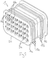
- Fig. 1 shows a passage 1 according to the invention which is poured into a wall 2 made of concrete.
- the implementation 1 is in each case flush with the two side surfaces 3a, b of the wall 2.
- the formwork delimits a cavity where now the side surfaces 3a, b of the wall 2 are located.
- the implementation 1 has 24 double clutch pieces 4 in their interior, which are not cut for clarity, but shown in side view.
- Each of the double clutch pieces 4 has two plug-in fittings, namely one at each of its two opposite ends.
- a hollow tube section of the left side in the figure of the wall 2 and a hollow tube section of the right side of the wall 2 are inserted in the figure.
- the two hollow tubular sections are connected to each other via the respective double clutch piece 4;
- the hollow tube can be functionally passed through the wall 2.
- a fiber optic cable can be performed.
- each of the double clutch pieces 4 by means of the two front panels 5a, b still covered on both sides of the wall 2 out.
- a closure lid 7 is arranged in each of the channels 6, in each case in the double clutch piece-free section 6aa, 6ba.
- the closure cover 7 protect the double clutch pieces 4 before and during assembly and seal the channels 6 sealing. It must therefore the implementation 1 then not immediately occupied with a number of their number of double coupling pieces 4 corresponding number of lines, but is also a partial occupancy possible.
- the closure cover 7 remain in the unoccupied double clutch pieces 4 as a water ingress-hindering blind seals.
- each of the closure lids 7 is provided with a gripping portion 9 at its respective side opposite the respective double-clutch piece 4, that is to say on the outside.
- Fig. 1 the gripping portions 9 are also cut;
- Fig. 2 In oblique view, its extension (perpendicular to the plane of the drawing in FIG Fig. 1 ) recognize better.
- the gripping sections 9 each represent a web rising away from the respective closing lid 7, which can be easily grasped with a pair of pliers.
- Each of the double clutch pieces 4 has at its two ends in each case a plug-in fitting 10 into which a hollow tube can be inserted after removal of the respective closure cap 7 from the respective side of the wall 2.
- the hollow tube is then sealed against the plug-in fitting 10 and at the same time securely held therein due to a lock.
- the double clutch piece-free sections 6aa, 6ba of the channels 6 each one opposite the other channel inner wall 11 inwardly away uplifting, circumferential web 12 is provided as a scraper. This rubs off when inserting the hollow tube on the outer wall of adhesive contaminants.
- each of the two front panels 5 On the outside of each of the two front panels 5 are each further three web seals 13 are provided, in each case completely circumferentially. These land seals 13 block moisture paths along the outside of the duct 1 from one side of the wall 2 to the other.
- Fig. 2 shows the implementation 1 before installation in the wall 2 in an oblique view.
- the same reference numerals designate the same parts and, to that extent, reference is also made in each case to the description of the other figures.
- Fig. 2 In the oblique view according to Fig. 2 is on the front panel 5 also a the channels 6 and thus the double clutch pieces 4 associated numbering to recognize.
- the numbering is doubly provided as a first sequence of numbers 22a and a second sequence of numbers 22b, so there are two numbers assigned to each dual clutch 4.
- the reason for this is that the front panel 5 is made by pressing into a mold, with the numbering 22 already taken into account in the mold. So now the two then oppositely arranged front panels 5 made with the same mold two-fold numbering is provided for.
- Fig. 3 again shows a front panel 5a in a sectional side view, and indeed only the front panel 5a without double clutch pieces 4.
- This shows the inner contour of the portions of the channels 6, in which in the composite implementation 1, the dual clutch pieces 4 are inserted.
- the channel inner wall 11a is formed in this section with a plurality of inwardly protruding protrusions 31a which are connected to one (in FIG Fig. 1 not apparent) outer contour of the respective double clutch piece 4 are complementary.
- Fig. 4 shows the front panel in a plan view, as it is then visible from one side of the wall after setting in concrete.
- the closure lid 7a can be seen with the respective gripping sections 9a.
- the numbering 22 can be seen, ie the first 22a and the second number sequence 22b, with which the dual clutch pieces 4 are each assigned two numbers (which is why an identical front panel mirrored and rotated on the opposite side can be mounted).
Landscapes
- Engineering & Computer Science (AREA)
- General Engineering & Computer Science (AREA)
- Architecture (AREA)
- Mechanical Engineering (AREA)
- Civil Engineering (AREA)
- Structural Engineering (AREA)
- Forms Removed On Construction Sites Or Auxiliary Members Thereof (AREA)
Priority Applications (2)
| Application Number | Priority Date | Filing Date | Title |
|---|---|---|---|
| PL15156782T PL3061890T3 (pl) | 2015-02-26 | 2015-02-26 | Przepust do zalania betonem |
| EP15156782.3A EP3061890B1 (de) | 2015-02-26 | 2015-02-26 | Durchführung zum Vergießen mit Beton |
Applications Claiming Priority (1)
| Application Number | Priority Date | Filing Date | Title |
|---|---|---|---|
| EP15156782.3A EP3061890B1 (de) | 2015-02-26 | 2015-02-26 | Durchführung zum Vergießen mit Beton |
Publications (2)
| Publication Number | Publication Date |
|---|---|
| EP3061890A1 EP3061890A1 (de) | 2016-08-31 |
| EP3061890B1 true EP3061890B1 (de) | 2017-09-20 |
Family
ID=52595120
Family Applications (1)
| Application Number | Title | Priority Date | Filing Date |
|---|---|---|---|
| EP15156782.3A Active EP3061890B1 (de) | 2015-02-26 | 2015-02-26 | Durchführung zum Vergießen mit Beton |
Country Status (2)
| Country | Link |
|---|---|
| EP (1) | EP3061890B1 (pl) |
| PL (1) | PL3061890T3 (pl) |
Cited By (1)
| Publication number | Priority date | Publication date | Assignee | Title |
|---|---|---|---|---|
| EP3995726A1 (en) * | 2020-11-10 | 2022-05-11 | VILPE Oy | Leadthrough kit and method of leading ventilation channels through a structure |
Families Citing this family (1)
| Publication number | Priority date | Publication date | Assignee | Title |
|---|---|---|---|---|
| PL3672003T3 (pl) * | 2018-12-17 | 2024-03-04 | Hauff-Technik Gmbh & Co. Kg | Zastosowanie przepustu do zalewania w ściennym elemencie |
Family Cites Families (4)
| Publication number | Priority date | Publication date | Assignee | Title |
|---|---|---|---|---|
| BE788705A (fr) * | 1971-12-03 | 1973-01-02 | Formex Mfg Inc | Termineur de conduit |
| EP0246219B1 (de) * | 1986-05-15 | 1989-10-25 | "Poloplast" Kunststoffwerk der Knoch, Kern & Co., OHG | Rohrdurchführung |
| DE19528685C2 (de) * | 1995-08-03 | 1999-02-18 | Berndt Saurwein | Vorrichtung zur Herstellung von Installationsdurchbrüchen |
| DE202005001153U1 (de) * | 2005-01-24 | 2006-06-08 | Voss Automotive Gmbh | Kupplungseinrichtung für Medienleitungen |
-
2015
- 2015-02-26 EP EP15156782.3A patent/EP3061890B1/de active Active
- 2015-02-26 PL PL15156782T patent/PL3061890T3/pl unknown
Non-Patent Citations (1)
| Title |
|---|
| None * |
Cited By (2)
| Publication number | Priority date | Publication date | Assignee | Title |
|---|---|---|---|---|
| EP3995726A1 (en) * | 2020-11-10 | 2022-05-11 | VILPE Oy | Leadthrough kit and method of leading ventilation channels through a structure |
| EP4335962A3 (en) * | 2020-11-10 | 2024-05-22 | VILPE Oy | Leadthrough kit and method of leading ventilation channels through a structure |
Also Published As
| Publication number | Publication date |
|---|---|
| EP3061890A1 (de) | 2016-08-31 |
| PL3061890T3 (pl) | 2018-02-28 |
Similar Documents
| Publication | Publication Date | Title |
|---|---|---|
| WO2015110290A1 (de) | Durchführung zum einbau in einem wand- oder bodenelement | |
| EP3026766B1 (de) | Rohreinführung für eine unterputzdose | |
| EP3534476B1 (de) | Installationsdose | |
| EP3061890B1 (de) | Durchführung zum Vergießen mit Beton | |
| DE10053115C1 (de) | Anordnung zur Durchführung eines Leitungsstranges und Verfahren zur Herstellung einer solchen Anordnung | |
| DE202009003184U1 (de) | Dichtungsvorrichtung zum Abdichten eines Durchbruchs | |
| DE202014003306U1 (de) | Durchführung zum Einbau in ein Wand- oder Bodenelement | |
| DE202015001458U1 (de) | Durchführung zum Vergießen mit Beton | |
| EP3582351B1 (de) | Verwendung einer gebäudewandeinführung zum einbau in eine gebäudewand | |
| EP2887478B1 (de) | Einbau einer Leitung in ein Wand- oder Bodenelement | |
| EP2363552B1 (de) | Verwendung eines Aufsatzstückes zum Aufsetzen auf eine Dichtpackung | |
| EP3678777A1 (de) | Napf oder napfstreifen und verfahren zu seiner herstellung | |
| DE202014000524U1 (de) | Durchführung zum Einbau in einem Wand- oder Bodenelement | |
| DE202011108274U1 (de) | Adapterring zum Einsetzen in ein Rohrelement einer Leitungsdurchführung | |
| DE102014102260B4 (de) | Baukasten für die Abdichtung des Durchganges von Kabeln oder Adern, die durch eine Platte verlaufen sowie Verfahren zum Abdichten | |
| DE102018005720B4 (de) | Verwendung einer Durchführung zum Eingießen in eine Bodenplatte | |
| DE102010011173A1 (de) | Dichtungsanordnung für Schalungen | |
| EP2937493A1 (de) | Durchführung zum Einbau in ein Wand- oder Bodenelement | |
| EP2851488B1 (de) | Verfahren zum Herstellen eines Wand- oder Bodenelements und Verwendung eines Aufsetzstücks in einem solchen Verfahren | |
| EP2597344A1 (de) | Adapterring zum Einsetzen in ein Rohrelement einer Leitungsdurchführung | |
| DE102023200338B3 (de) | Kabeldurchführung sowie Verfahren zur Herstellung einer Kabeldurchführung | |
| EP4194625B1 (de) | Rohranschlussanordnung | |
| DE202012001169U1 (de) | Verwendung eines Stopfens zusammen mit einer Expansionsdichtung | |
| DE202017002654U1 (de) | Durchführung zum Einbau in ein Wand- oder Bodenelement | |
| DE102012002198B4 (de) | Verwendung eines Stopfens zusammen mit einer Expansionsdichtung, Verfahren zur Herstellung des Stopfens und Leitungsdurchführungsset mit entsprechendem Stopfen |
Legal Events
| Date | Code | Title | Description |
|---|---|---|---|
| PUAI | Public reference made under article 153(3) epc to a published international application that has entered the european phase |
Free format text: ORIGINAL CODE: 0009012 |
|
| AK | Designated contracting states |
Kind code of ref document: A1 Designated state(s): AL AT BE BG CH CY CZ DE DK EE ES FI FR GB GR HR HU IE IS IT LI LT LU LV MC MK MT NL NO PL PT RO RS SE SI SK SM TR |
|
| AX | Request for extension of the european patent |
Extension state: BA ME |
|
| STAA | Information on the status of an ep patent application or granted ep patent |
Free format text: STATUS: REQUEST FOR EXAMINATION WAS MADE |
|
| RBV | Designated contracting states (corrected) |
Designated state(s): AL AT BE BG CH CY CZ DE DK EE ES FI FR GB GR HR HU IE IS IT LI LT LU LV MC MK MT NL NO PL PT RO RS SE SI SK SM TR |
|
| 17P | Request for examination filed |
Effective date: 20160708 |
|
| GRAP | Despatch of communication of intention to grant a patent |
Free format text: ORIGINAL CODE: EPIDOSNIGR1 |
|
| STAA | Information on the status of an ep patent application or granted ep patent |
Free format text: STATUS: GRANT OF PATENT IS INTENDED |
|
| RIC1 | Information provided on ipc code assigned before grant |
Ipc: H02G 3/22 20060101ALI20170320BHEP Ipc: E04G 15/06 20060101AFI20170320BHEP Ipc: F16L 5/12 20060101ALI20170320BHEP Ipc: F16L 5/14 20060101ALI20170320BHEP |
|
| INTG | Intention to grant announced |
Effective date: 20170419 |
|
| GRAS | Grant fee paid |
Free format text: ORIGINAL CODE: EPIDOSNIGR3 |
|
| GRAA | (expected) grant |
Free format text: ORIGINAL CODE: 0009210 |
|
| STAA | Information on the status of an ep patent application or granted ep patent |
Free format text: STATUS: THE PATENT HAS BEEN GRANTED |
|
| AK | Designated contracting states |
Kind code of ref document: B1 Designated state(s): AL AT BE BG CH CY CZ DE DK EE ES FI FR GB GR HR HU IE IS IT LI LT LU LV MC MK MT NL NO PL PT RO RS SE SI SK SM TR |
|
| REG | Reference to a national code |
Ref country code: GB Ref legal event code: FG4D Free format text: NOT ENGLISH |
|
| REG | Reference to a national code |
Ref country code: CH Ref legal event code: EP |
|
| REG | Reference to a national code |
Ref country code: CH Ref legal event code: NV Representative=s name: E. BLUM AND CO. AG PATENT- UND MARKENANWAELTE , CH |
|
| REG | Reference to a national code |
Ref country code: AT Ref legal event code: REF Ref document number: 930234 Country of ref document: AT Kind code of ref document: T Effective date: 20171015 |
|
| REG | Reference to a national code |
Ref country code: IE Ref legal event code: FG4D Free format text: LANGUAGE OF EP DOCUMENT: GERMAN |
|
| REG | Reference to a national code |
Ref country code: DE Ref legal event code: R096 Ref document number: 502015001923 Country of ref document: DE |
|
| REG | Reference to a national code |
Ref country code: SE Ref legal event code: TRGR |
|
| REG | Reference to a national code |
Ref country code: NL Ref legal event code: FP |
|
| PG25 | Lapsed in a contracting state [announced via postgrant information from national office to epo] |
Ref country code: HR Free format text: LAPSE BECAUSE OF FAILURE TO SUBMIT A TRANSLATION OF THE DESCRIPTION OR TO PAY THE FEE WITHIN THE PRESCRIBED TIME-LIMIT Effective date: 20170920 Ref country code: NO Free format text: LAPSE BECAUSE OF FAILURE TO SUBMIT A TRANSLATION OF THE DESCRIPTION OR TO PAY THE FEE WITHIN THE PRESCRIBED TIME-LIMIT Effective date: 20171220 Ref country code: FI Free format text: LAPSE BECAUSE OF FAILURE TO SUBMIT A TRANSLATION OF THE DESCRIPTION OR TO PAY THE FEE WITHIN THE PRESCRIBED TIME-LIMIT Effective date: 20170920 Ref country code: LT Free format text: LAPSE BECAUSE OF FAILURE TO SUBMIT A TRANSLATION OF THE DESCRIPTION OR TO PAY THE FEE WITHIN THE PRESCRIBED TIME-LIMIT Effective date: 20170920 |
|
| REG | Reference to a national code |
Ref country code: LT Ref legal event code: MG4D |
|
| REG | Reference to a national code |
Ref country code: FR Ref legal event code: PLFP Year of fee payment: 4 |
|
| PG25 | Lapsed in a contracting state [announced via postgrant information from national office to epo] |
Ref country code: GR Free format text: LAPSE BECAUSE OF FAILURE TO SUBMIT A TRANSLATION OF THE DESCRIPTION OR TO PAY THE FEE WITHIN THE PRESCRIBED TIME-LIMIT Effective date: 20171221 Ref country code: LV Free format text: LAPSE BECAUSE OF FAILURE TO SUBMIT A TRANSLATION OF THE DESCRIPTION OR TO PAY THE FEE WITHIN THE PRESCRIBED TIME-LIMIT Effective date: 20170920 Ref country code: BG Free format text: LAPSE BECAUSE OF FAILURE TO SUBMIT A TRANSLATION OF THE DESCRIPTION OR TO PAY THE FEE WITHIN THE PRESCRIBED TIME-LIMIT Effective date: 20171220 Ref country code: RS Free format text: LAPSE BECAUSE OF FAILURE TO SUBMIT A TRANSLATION OF THE DESCRIPTION OR TO PAY THE FEE WITHIN THE PRESCRIBED TIME-LIMIT Effective date: 20170920 |
|
| PG25 | Lapsed in a contracting state [announced via postgrant information from national office to epo] |
Ref country code: RO Free format text: LAPSE BECAUSE OF FAILURE TO SUBMIT A TRANSLATION OF THE DESCRIPTION OR TO PAY THE FEE WITHIN THE PRESCRIBED TIME-LIMIT Effective date: 20170920 Ref country code: ES Free format text: LAPSE BECAUSE OF FAILURE TO SUBMIT A TRANSLATION OF THE DESCRIPTION OR TO PAY THE FEE WITHIN THE PRESCRIBED TIME-LIMIT Effective date: 20170920 |
|
| PG25 | Lapsed in a contracting state [announced via postgrant information from national office to epo] |
Ref country code: SM Free format text: LAPSE BECAUSE OF FAILURE TO SUBMIT A TRANSLATION OF THE DESCRIPTION OR TO PAY THE FEE WITHIN THE PRESCRIBED TIME-LIMIT Effective date: 20170920 Ref country code: IS Free format text: LAPSE BECAUSE OF FAILURE TO SUBMIT A TRANSLATION OF THE DESCRIPTION OR TO PAY THE FEE WITHIN THE PRESCRIBED TIME-LIMIT Effective date: 20180120 Ref country code: SK Free format text: LAPSE BECAUSE OF FAILURE TO SUBMIT A TRANSLATION OF THE DESCRIPTION OR TO PAY THE FEE WITHIN THE PRESCRIBED TIME-LIMIT Effective date: 20170920 Ref country code: EE Free format text: LAPSE BECAUSE OF FAILURE TO SUBMIT A TRANSLATION OF THE DESCRIPTION OR TO PAY THE FEE WITHIN THE PRESCRIBED TIME-LIMIT Effective date: 20170920 |
|
| REG | Reference to a national code |
Ref country code: DE Ref legal event code: R097 Ref document number: 502015001923 Country of ref document: DE |
|
| PLBE | No opposition filed within time limit |
Free format text: ORIGINAL CODE: 0009261 |
|
| STAA | Information on the status of an ep patent application or granted ep patent |
Free format text: STATUS: NO OPPOSITION FILED WITHIN TIME LIMIT |
|
| PG25 | Lapsed in a contracting state [announced via postgrant information from national office to epo] |
Ref country code: DK Free format text: LAPSE BECAUSE OF FAILURE TO SUBMIT A TRANSLATION OF THE DESCRIPTION OR TO PAY THE FEE WITHIN THE PRESCRIBED TIME-LIMIT Effective date: 20170920 |
|
| 26N | No opposition filed |
Effective date: 20180621 |
|
| PG25 | Lapsed in a contracting state [announced via postgrant information from national office to epo] |
Ref country code: MT Free format text: LAPSE BECAUSE OF FAILURE TO SUBMIT A TRANSLATION OF THE DESCRIPTION OR TO PAY THE FEE WITHIN THE PRESCRIBED TIME-LIMIT Effective date: 20170920 Ref country code: MC Free format text: LAPSE BECAUSE OF FAILURE TO SUBMIT A TRANSLATION OF THE DESCRIPTION OR TO PAY THE FEE WITHIN THE PRESCRIBED TIME-LIMIT Effective date: 20170920 |
|
| REG | Reference to a national code |
Ref country code: BE Ref legal event code: MM Effective date: 20180228 |
|
| PG25 | Lapsed in a contracting state [announced via postgrant information from national office to epo] |
Ref country code: SI Free format text: LAPSE BECAUSE OF FAILURE TO SUBMIT A TRANSLATION OF THE DESCRIPTION OR TO PAY THE FEE WITHIN THE PRESCRIBED TIME-LIMIT Effective date: 20170920 |
|
| REG | Reference to a national code |
Ref country code: IE Ref legal event code: MM4A |
|
| PG25 | Lapsed in a contracting state [announced via postgrant information from national office to epo] |
Ref country code: IE Free format text: LAPSE BECAUSE OF NON-PAYMENT OF DUE FEES Effective date: 20180226 |
|
| PG25 | Lapsed in a contracting state [announced via postgrant information from national office to epo] |
Ref country code: BE Free format text: LAPSE BECAUSE OF NON-PAYMENT OF DUE FEES Effective date: 20180228 |
|
| PGFP | Annual fee paid to national office [announced via postgrant information from national office to epo] |
Ref country code: FI Payment date: 20190211 Year of fee payment: 14 Ref country code: IT Payment date: 20190222 Year of fee payment: 5 |
|
| PGFP | Annual fee paid to national office [announced via postgrant information from national office to epo] |
Ref country code: FR Payment date: 20190221 Year of fee payment: 5 Ref country code: SE Payment date: 20190221 Year of fee payment: 5 |
|
| GBPC | Gb: european patent ceased through non-payment of renewal fee |
Effective date: 20190226 |
|
| PG25 | Lapsed in a contracting state [announced via postgrant information from national office to epo] |
Ref country code: GB Free format text: LAPSE BECAUSE OF NON-PAYMENT OF DUE FEES Effective date: 20190226 |
|
| PG25 | Lapsed in a contracting state [announced via postgrant information from national office to epo] |
Ref country code: TR Free format text: LAPSE BECAUSE OF FAILURE TO SUBMIT A TRANSLATION OF THE DESCRIPTION OR TO PAY THE FEE WITHIN THE PRESCRIBED TIME-LIMIT Effective date: 20170920 |
|
| PG25 | Lapsed in a contracting state [announced via postgrant information from national office to epo] |
Ref country code: PT Free format text: LAPSE BECAUSE OF FAILURE TO SUBMIT A TRANSLATION OF THE DESCRIPTION OR TO PAY THE FEE WITHIN THE PRESCRIBED TIME-LIMIT Effective date: 20170920 |
|
| PG25 | Lapsed in a contracting state [announced via postgrant information from national office to epo] |
Ref country code: CY Free format text: LAPSE BECAUSE OF FAILURE TO SUBMIT A TRANSLATION OF THE DESCRIPTION OR TO PAY THE FEE WITHIN THE PRESCRIBED TIME-LIMIT Effective date: 20170920 Ref country code: MK Free format text: LAPSE BECAUSE OF NON-PAYMENT OF DUE FEES Effective date: 20170920 Ref country code: HU Free format text: LAPSE BECAUSE OF FAILURE TO SUBMIT A TRANSLATION OF THE DESCRIPTION OR TO PAY THE FEE WITHIN THE PRESCRIBED TIME-LIMIT; INVALID AB INITIO Effective date: 20150226 |
|
| PG25 | Lapsed in a contracting state [announced via postgrant information from national office to epo] |
Ref country code: AL Free format text: LAPSE BECAUSE OF FAILURE TO SUBMIT A TRANSLATION OF THE DESCRIPTION OR TO PAY THE FEE WITHIN THE PRESCRIBED TIME-LIMIT Effective date: 20170920 |
|
| REG | Reference to a national code |
Ref country code: SE Ref legal event code: EUG |
|
| PG25 | Lapsed in a contracting state [announced via postgrant information from national office to epo] |
Ref country code: CZ Free format text: LAPSE BECAUSE OF NON-PAYMENT OF DUE FEES Effective date: 20200226 Ref country code: LU Free format text: LAPSE BECAUSE OF NON-PAYMENT OF DUE FEES Effective date: 20200226 Ref country code: SE Free format text: LAPSE BECAUSE OF NON-PAYMENT OF DUE FEES Effective date: 20200227 |
|
| PG25 | Lapsed in a contracting state [announced via postgrant information from national office to epo] |
Ref country code: FR Free format text: LAPSE BECAUSE OF NON-PAYMENT OF DUE FEES Effective date: 20200229 |
|
| PG25 | Lapsed in a contracting state [announced via postgrant information from national office to epo] |
Ref country code: IT Free format text: LAPSE BECAUSE OF NON-PAYMENT OF DUE FEES Effective date: 20200226 |
|
| PGFP | Annual fee paid to national office [announced via postgrant information from national office to epo] |
Ref country code: NL Payment date: 20220216 Year of fee payment: 8 |
|
| PG25 | Lapsed in a contracting state [announced via postgrant information from national office to epo] |
Ref country code: PL Free format text: LAPSE BECAUSE OF NON-PAYMENT OF DUE FEES Effective date: 20200226 |
|
| PGFP | Annual fee paid to national office [announced via postgrant information from national office to epo] |
Ref country code: CH Payment date: 20230307 Year of fee payment: 9 Ref country code: AT Payment date: 20230215 Year of fee payment: 9 |
|
| P01 | Opt-out of the competence of the unified patent court (upc) registered |
Effective date: 20230428 |
|
| REG | Reference to a national code |
Ref country code: NL Ref legal event code: MM Effective date: 20230301 |
|
| PG25 | Lapsed in a contracting state [announced via postgrant information from national office to epo] |
Ref country code: NL Free format text: LAPSE BECAUSE OF NON-PAYMENT OF DUE FEES Effective date: 20230301 |
|
| REG | Reference to a national code |
Ref country code: CH Ref legal event code: PL |
|
| REG | Reference to a national code |
Ref country code: AT Ref legal event code: MM01 Ref document number: 930234 Country of ref document: AT Kind code of ref document: T Effective date: 20240226 |
|
| PG25 | Lapsed in a contracting state [announced via postgrant information from national office to epo] |
Ref country code: CH Free format text: LAPSE BECAUSE OF NON-PAYMENT OF DUE FEES Effective date: 20240229 |
|
| PG25 | Lapsed in a contracting state [announced via postgrant information from national office to epo] |
Ref country code: AT Free format text: LAPSE BECAUSE OF NON-PAYMENT OF DUE FEES Effective date: 20240226 |
|
| PG25 | Lapsed in a contracting state [announced via postgrant information from national office to epo] |
Ref country code: CH Free format text: LAPSE BECAUSE OF NON-PAYMENT OF DUE FEES Effective date: 20240229 Ref country code: AT Free format text: LAPSE BECAUSE OF NON-PAYMENT OF DUE FEES Effective date: 20240226 |
|
| REG | Reference to a national code |
Ref country code: DE Ref legal event code: R082 Ref document number: 502015001923 Country of ref document: DE Representative=s name: SZYNKA SMORODIN PATENTANWAELTE PARTNERSCHAFT M, DE |
|
| PGFP | Annual fee paid to national office [announced via postgrant information from national office to epo] |
Ref country code: DE Payment date: 20250218 Year of fee payment: 11 |