EP3061291B1 - Hochgeschwindigkeitskommunikation für fahrzeuge - Google Patents
Hochgeschwindigkeitskommunikation für fahrzeuge Download PDFInfo
- Publication number
- EP3061291B1 EP3061291B1 EP14790280.3A EP14790280A EP3061291B1 EP 3061291 B1 EP3061291 B1 EP 3061291B1 EP 14790280 A EP14790280 A EP 14790280A EP 3061291 B1 EP3061291 B1 EP 3061291B1
- Authority
- EP
- European Patent Office
- Prior art keywords
- mobile terminal
- access nodes
- location
- predetermined time
- network
- Prior art date
- Legal status (The legal status is an assumption and is not a legal conclusion. Google has not performed a legal analysis and makes no representation as to the accuracy of the status listed.)
- Active
Links
Images




Classifications
-
- H—ELECTRICITY
- H04—ELECTRIC COMMUNICATION TECHNIQUE
- H04L—TRANSMISSION OF DIGITAL INFORMATION, e.g. TELEGRAPHIC COMMUNICATION
- H04L5/00—Arrangements affording multiple use of the transmission path
- H04L5/003—Arrangements for allocating sub-channels of the transmission path
- H04L5/0032—Distributed allocation, i.e. involving a plurality of allocating devices, each making partial allocation
- H04L5/0035—Resource allocation in a cooperative multipoint environment
-
- H—ELECTRICITY
- H04—ELECTRIC COMMUNICATION TECHNIQUE
- H04B—TRANSMISSION
- H04B7/00—Radio transmission systems, i.e. using radiation field
- H04B7/02—Diversity systems; Multi-antenna system, i.e. transmission or reception using multiple antennas
- H04B7/022—Site diversity; Macro-diversity
- H04B7/024—Co-operative use of antennas of several sites, e.g. in co-ordinated multipoint or co-operative multiple-input multiple-output [MIMO] systems
-
- H—ELECTRICITY
- H04—ELECTRIC COMMUNICATION TECHNIQUE
- H04L—TRANSMISSION OF DIGITAL INFORMATION, e.g. TELEGRAPHIC COMMUNICATION
- H04L5/00—Arrangements affording multiple use of the transmission path
- H04L5/003—Arrangements for allocating sub-channels of the transmission path
- H04L5/0058—Allocation criteria
- H04L5/0069—Allocation based on distance or geographical location
-
- H—ELECTRICITY
- H04—ELECTRIC COMMUNICATION TECHNIQUE
- H04W—WIRELESS COMMUNICATION NETWORKS
- H04W36/00—Hand-off or reselection arrangements
- H04W36/0005—Control or signalling for completing the hand-off
- H04W36/0055—Transmission or use of information for re-establishing the radio link
- H04W36/0069—Transmission or use of information for re-establishing the radio link in case of dual connectivity, e.g. decoupled uplink/downlink
- H04W36/00692—Transmission or use of information for re-establishing the radio link in case of dual connectivity, e.g. decoupled uplink/downlink using simultaneous multiple data streams, e.g. cooperative multipoint [CoMP], carrier aggregation [CA] or multiple input multiple output [MIMO]
-
- H—ELECTRICITY
- H04—ELECTRIC COMMUNICATION TECHNIQUE
- H04W—WIRELESS COMMUNICATION NETWORKS
- H04W36/00—Hand-off or reselection arrangements
- H04W36/24—Reselection being triggered by specific parameters
- H04W36/32—Reselection being triggered by specific parameters by location or mobility data, e.g. speed data
- H04W36/322—Reselection being triggered by specific parameters by location or mobility data, e.g. speed data by location data
-
- H—ELECTRICITY
- H04—ELECTRIC COMMUNICATION TECHNIQUE
- H04W—WIRELESS COMMUNICATION NETWORKS
- H04W36/00—Hand-off or reselection arrangements
- H04W36/24—Reselection being triggered by specific parameters
- H04W36/32—Reselection being triggered by specific parameters by location or mobility data, e.g. speed data
- H04W36/324—Reselection being triggered by specific parameters by location or mobility data, e.g. speed data by mobility data, e.g. speed data
-
- H—ELECTRICITY
- H04—ELECTRIC COMMUNICATION TECHNIQUE
- H04W—WIRELESS COMMUNICATION NETWORKS
- H04W4/00—Services specially adapted for wireless communication networks; Facilities therefor
- H04W4/02—Services making use of location information
- H04W4/029—Location-based management or tracking services
-
- H—ELECTRICITY
- H04—ELECTRIC COMMUNICATION TECHNIQUE
- H04W—WIRELESS COMMUNICATION NETWORKS
- H04W4/00—Services specially adapted for wireless communication networks; Facilities therefor
- H04W4/50—Service provisioning or reconfiguring
-
- H—ELECTRICITY
- H04—ELECTRIC COMMUNICATION TECHNIQUE
- H04W—WIRELESS COMMUNICATION NETWORKS
- H04W64/00—Locating users or terminals or network equipment for network management purposes, e.g. mobility management
- H04W64/006—Locating users or terminals or network equipment for network management purposes, e.g. mobility management with additional information processing, e.g. for direction or speed determination
-
- H—ELECTRICITY
- H04—ELECTRIC COMMUNICATION TECHNIQUE
- H04L—TRANSMISSION OF DIGITAL INFORMATION, e.g. TELEGRAPHIC COMMUNICATION
- H04L5/00—Arrangements affording multiple use of the transmission path
- H04L5/003—Arrangements for allocating sub-channels of the transmission path
- H04L5/0058—Allocation criteria
- H04L5/006—Quality of the received signal, e.g. BER, SNR, water filling
-
- H—ELECTRICITY
- H04—ELECTRIC COMMUNICATION TECHNIQUE
- H04L—TRANSMISSION OF DIGITAL INFORMATION, e.g. TELEGRAPHIC COMMUNICATION
- H04L5/00—Arrangements affording multiple use of the transmission path
- H04L5/003—Arrangements for allocating sub-channels of the transmission path
- H04L5/0058—Allocation criteria
- H04L5/0075—Allocation using proportional fairness
-
- H—ELECTRICITY
- H04—ELECTRIC COMMUNICATION TECHNIQUE
- H04W—WIRELESS COMMUNICATION NETWORKS
- H04W4/00—Services specially adapted for wireless communication networks; Facilities therefor
- H04W4/30—Services specially adapted for particular environments, situations or purposes
- H04W4/40—Services specially adapted for particular environments, situations or purposes for vehicles, e.g. vehicle-to-pedestrians [V2P]
- H04W4/42—Services specially adapted for particular environments, situations or purposes for vehicles, e.g. vehicle-to-pedestrians [V2P] for mass transport vehicles, e.g. buses, trains or aircraft
Definitions
- the present invention concerns a network entity of a cellular communications network that comprises a plurality of geographically distributed access nodes arranged for communication with mobile terminals and a method for configuring such a cellular communications network.
- LTE Long Term Evolution
- a second problem relates to channel estimation both at the transmitter and the receiver in both uplink and downlink.
- Channel estimation is used in order to, for example, equalise, synchronise, remove interference in a received signal and any combination of these.
- Current channel estimation techniques can provide robust channel estimation at low speed, but use for high speed mobile terminals results in a coarse channel estimation. As the mobile terminal moves, the channel changes such that previous channel estimations may no longer be valid and cannot be used in a reliable way. This problem clearly increases as the mobile terminal's velocity gets higher and further limits the data rate that can be provided.
- Each cell is normally designed to service a particular geographical coverage area.
- a handover procedure is required.
- a mobile terminal may pass through the coverage areas of different cells for a relatively short period of time.
- the frequency of handover can therefore become quite high. This places further strain on the network, increasing overheads and making it more difficult for a high data rate service to be provided.
- Another, fourth problem relates to the mechanisms by which signalling is effected in existing cellular communications networks.
- Data rates can be increased by providing feedback from the mobile terminal to the network. When the mobile terminal is travelling at a high velocity, this feedback may not provide any improvement and indeed, may actually degrade the data rate provided. This is because the feedback may be inaccurate or void of any practical value as it relates to a situation that has changed, due to the movement of the mobile terminal.
- the first example relates to racing cars. These can drive at speeds of the order of 360km/hr (220mph). Communication to and from the car may include: audio communication with the pit; telemetry (temperatures, pressures or vital information such as tyre wear) and one-way video broadcast from the car to the pit, team and television broadcasting.
- a car may have over 120 sensors and live telemetry is therefore an important part of the communications in such systems.
- 1.5Gbyte of data may be gathered from sensors in each car.
- the typical error-corrected RF-payload is of the order of 2Mbps in a 2Mhz spectrum.
- the telemetry is transmitted using coded OFDM in the L-band (40MHz bandwidth) between 1.4GHz and 1.65GHz. Telemetries from different cars are frequency multiplexed, to avoid interference and provide a measure of confidentiality between the teams.
- the required data rate for high definition video is in the order of 7 to 14Mbps.
- OFDM-based technologies can suffer from high Doppler impact, since the shifting and widening of each subcarrier can reduce orthogonality between them and increase inter-carrier interference.
- Race regulations can require a minimum of five video cameras on-board the car.
- those videos delivered using fourth generation (4G) cellular technologies such as WiMAX or LTE.
- the typical transmission bit rate may be 5Mbps per car. If a race has twenty or more cars, the demand placed on the network can be high.
- the second example relates to passenger trains. Train customers increasingly expect the provision of high speed data either using a Wireless Local Area Network (WLAN) or using cellular technologies.
- WLAN Wireless Local Area Network
- One technical solution used is to have a local transmitter on a train (either WLAN, cellular or both) and service this transmitter with a high bandwidth back haul link.
- a typical train may have 600 seats.
- the possibility of more than one 1000 mobile terminals needing to be serviced across the train is not inconceivable.
- the back haul link to the train would desirably have a very high data rate.
- CoMP Cooperative Multipoint
- CoMP is able to cancel this interference by sending feedback from each cell to the other about the signal transmitted by the user serviced by that cell.
- the other cell can then use the feedback signal together with an estimation of the channel to cancel the interference.
- TR Technical Report
- An evaluation of CoMP in 3GPP Technical Report (TR) 36.819 was for 3GPP "case 1" at a speed of 3km/hr (as defined in 3GPP TR 36.913 ). Its use when the mobile terminal is travelling at a high velocity is not envisaged, partly because the requirement for feedback cannot readily be met.
- MIMO techniques have also been used to achieve higher data rates within a single cell. At high mobile velocities, the channel estimation requirements to use MIMO are problematic.
- a CoMP soft handover scheme for LTE systems in high speed railway discusses a scheme using an dual-antenna system on a train-based mobile terminal for an LTE network in conjunction with CoMP.
- the use of two antennas allows improved handover, since the antenna at the rear of the train can benefit from the experience of the antenna at the front and thereby result in faster handover.
- the likelihood of coverage being lost at cell boundaries is reduced. The focus of this approach is therefore on reducing the call outage probability, but no consideration is made regarding the data rate provided over the cellular network, particularly outside the cell boundaries.
- US-2012/178468 relates to supporting a high-speed mobile terminal in a distributed antenna system.
- Information on a position and a speed of each terminal on a plurality of terminals is acquired and the plurality of terminals are mapped to at least one or more terminal groups based on at least one or more of the position or the speed of the terminal.
- US-2006/111149 relates to use of a dynamic beam forming for wireless communication signals in a wireless network.
- the present invention provides a network entity of a cellular communications network in accordance with claim 1.
- the cellular communications network comprises a plurality of geographically distributed access nodes arranged for communication with mobile terminals.
- the network entity comprises: a location prediction engine, configured to predict a location for a first mobile terminal at a predetermined time, based on location and/or movement data for the first mobile terminal; and a configuration output, arranged to configure two or more of the plurality of access nodes for cooperative communication with the first mobile terminal at the predetermined time, based on the predicted location for the first mobile terminal.
- EP-2 555 569 A1 and US-2013/0005374 use a predicted location for the mobile terminal to provide cross-layer optimisation, more efficient resource allocation and improved data rate. Location prediction is especially useful with regard to moving (that is, non-stationary) mobile terminals, such as vehicles. As discussed above, cooperative communication using multiple access nodes is also known for static or low-speed mobile terminals. It has now been recognised that the combination of these two techniques provides a synergy that significantly improves the data rate that can be achieved for mobile terminals travelling at high velocities.
- Location predication can assist in one or more of: estimating the channel using historical data; selection of suitable access nodes; appropriate resource allocation between access nodes; and many further benefits as discussed herein.
- the invention may be applied to a second mobile terminal (or further mobile terminals) in the same way as to the first mobile terminal or with possible improvements by sharing information between the mobile terminals.
- access node is intended to encompass a base station, cell transmitter, NodeB, eNodeB, an access point or similar technology.
- a cellular communications network can encompass any of those standardised and specified by 3GPP or similar bodies, wireless LAN technologies, WiMAX or other wireless access technology.
- Location data may comprise position, altitude, distance from a known point or other similar information, such as provided by global positioning technology (such as GPS, GLONASS or GALILEO or a combination of these) or similar location positioning technologies based on long-range or short-range systems (for example, short-range location identification using Bluetooth or similar).
- Movement data may comprise speed, velocity, direction or other characteristics of motion.
- the location prediction engine may use data based on one or more of: a global positioning technology (as discussed above); an accelerometer; and a compass. These sensors are used commonly in mobile telephones but not yet in modems. Combinations of these technologies may allow location and movement prediction with higher accuracy.
- the present invention may provide, in an aspect related to the first aspect, a mobile terminal of a cellular communications network.
- the cellular communications network comprises a plurality of geographically distributed access nodes arranged for communication with mobile terminals.
- the mobile terminal comprises: a first modem, for communicating with the cellular communications network; a second modem, for communicating with a local area network; a location identification engine, configured to identify a location for the mobile terminal and comprising one or more of: a global positioning technology; an accelerometer; and a compass.
- the mobile terminal may be configured to communicate the identified location to the cellular communications network through the first modem and a network entity of the cellular communications network may use the identified location to predict a future location for the mobile terminal.
- the combination of the first modem and the second modem may provide a gateway between the cellular communications network and the local area network, especially for Internet Protocol traffic.
- processes of adaptive learning, neural networks or both may be used to predict a location based on a previous location or other historic data. For example, trains or cars may travel multiple times along the same track and based on this, a probability of a location can be calculated from a previous location, for instance using the theory of Markov Chains (Markov model).
- the Markov model may be trained based on data from previous times, such as days or weeks.
- the predicted location may therefore be based on analytic data, which may comprise timetabling information, data about recent journeys (for example, information about delays in the last days or weeks or other similar data).
- the predicted location may be based on an indicator parameter, for example, the time. This may be possible when the location is intended to match a timetable or predictable by analytics.
- Historic data may be used alone or in combination with current data, as discussed above.
- the network entity further comprises selection logic, configured to select two or more of the plurality of access nodes, based on the predicted location for the first mobile terminal. Then, the configuration output is preferably arranged to configure the selected two or more access nodes for coordinated communication with the first mobile terminal.
- selection logic configured to select two or more of the plurality of access nodes, based on the predicted location for the first mobile terminal. Then, the configuration output is preferably arranged to configure the selected two or more access nodes for coordinated communication with the first mobile terminal.
- the network entity further comprises a resource allocation coordinator.
- a resource allocation coordinator This may be configured to determine resource allocation of the two or more access nodes for coordinated communication with the first mobile terminal at the predetermined time, based on the predicted location for the first mobile terminal.
- the configuration output is arranged to configure the determined resource allocation of the two or more access nodes.
- Resource allocation can cover a wide variety of issues, including transmission resources, reception resources and other access node or channel resources.
- the resource allocation determined for the two or more access nodes may comprise one or more of: a bandwidth allocation; transmission power allocation; a duty cycle allocation; and a power supply allocation.
- the resource allocation may be designed to split the resources at each access node between multiple mobile terminals.
- the location prediction engine may be further configured to predict the location for a second mobile at the predetermined time and this may optionally be based on location and/or movement data for the second mobile terminal.
- the resource allocation coordinator may then be further configured to determine resource allocation of the two or more access nodes for coordinated communication with the first mobile terminal and with the second mobile terminal at the predetermined time. This may then be based on the predicted location for the first mobile terminal and the predicted location for the second mobile terminal.
- the resources of the two or more access nodes may be limited and consequently may need to be divided between the two mobile terminals. Their location can be used in order to effect an improved allocation.
- the resource allocation coordinator may be further configured to establish activation characteristics for the plurality of access nodes, based on the predicted location for the first mobile terminal. Then, the configuration output may be arranged to activate and/or deactivate at least part of the two or more access nodes based on the established activation characteristics. This may be used to reduce energy consumption. For example, it may be understood that certain access nodes receive very little traffic. By predicting the location of the mobile terminal, an access node can be activated prior to its use by the mobile terminal, based on the mobile terminal's predicted location. Similarly, when the mobile terminal is predicted to be outside the coverage area of an access node it may be deactivated. Both of these approaches can be used together to activate and deactivate access nodes according to their need.
- the access node Only a part of the access node may be activated and/or deactivated.
- the physical layer components of the access node can be activated and/or deactivated (such as the transmitter, receiver and/or baseband processing), or the media access control (MAC) layer can be activated and/or deactivated.
- the Radio Access Network (RAN) of the access node can be activated and/or deactivated.
- a part of the access node such as a processor or back haul links may remain active.
- the network entity may further comprise antenna control logic, configured to determine antenna beam steering configurations of the two or more access nodes for coordinated communication with the first mobile terminal at the predetermined time, based on the predicted location for the first mobile terminal.
- the configuration output may then be arranged to set the determined antenna beam in configurations of the two or more access nodes.
- the access nodes can configure their antennas to provide directivity, enhancing reception of the mobile terminal's signal, improving the transmission efficiency to the mobile terminal or both. Coordinated communication by the access nodes improves the data rate provided for service between the access nodes and the mobile terminal.
- the configuration outputs may be further arranged to configure MIMO parameters for the two or more access nodes for coordinated communication with the first mobile terminal at the predetermined time, based on the predicted location for the first mobile terminal.
- the combination of the coordinated communication with MIMO may yield further benefits.
- MIMO operates using multiple antennas on the same cell, whereas CoMP works over two or more cells. MIMO operation does not normally imply co-operation of cells.
- the first mobile terminal comprises a plurality of communication systems. These communication systems may be independent, although they may be jointly controlled or jointly operated.
- the data outputs from the multiple communication systems may be combined or otherwise distributed between a common set of users.
- the configuration output may be arranged to configure the two or more access nodes for coordinated communication with each of the communication systems of the first mobile terminal at the predetermined time, based on the predicted location for the first mobile terminal.
- the communications systems of the first mobile terminal may be serviced by different access nodes or they may be serviced by the same access node.
- the configuration of the access nodes can be set to improve the aggregate data rate provided to all of the plurality of communication systems.
- the configuration output is further arranged to configure a first of the two or more access nodes for communication with a first communication system of the first mobile terminal and to configure a second of the two or more access nodes for communication with a second communication system of the first mobile terminal.
- the communication with the first and second communication systems may then be coordinated. This provides particular benefits, because the communications systems of the first mobile terminal may be able to provide feedback to each other regarding the signals transmitted, received or both with the respective access node. This may further improve the coordinated (or cooperative) communication.
- the location prediction engine may function in a variety of ways. For example, it may be configured to predict a location for the first mobile terminal at the predetermined time based on one or more of: a location for the first mobile terminal at a time for the predetermined time; a speed for the first mobile terminal at the time before the predetermined time; and a direction for the first mobile terminal at the time before the predetermined time.
- This data can be obtained for example, using positioning technology (as discussed above), using an indirect position determination, by knowledge of cell-site, analysis of transmissions received from the mobile terminal or other techniques known the skilled person.
- a prediction may be made regarding its location at a future time. For example, assumptions may be made about the change in velocity.
- the location prediction engine may be configured to predict a location for the first mobile terminal at the predetermined time, based on a predetermined travel route for the first mobile terminal. This can apply to certain types of vehicle, such as trains, racing cars, buses on a fixed route, trams and other types of vehicle that follow a known travel route.
- the cellular communications network advantageously comprises one or more of: a Wireless Local Area Network (LAN); a wireless Wide Area Network (WAN); and a mobile telecommunications network (using GSM, UMTS, LTE, WiMAX or other radio access technology).
- LAN Wireless Local Area Network
- WAN wireless Wide Area Network
- GSM Global System for Mobile communications
- a method for configuring a cellular communications network in line with claim 14. This comprises a plurality of geographically distributed access nodes arranged for communication with the mobile terminals. The method comprises: predicting a location for a first mobile terminal at a predetermined time, based on location and/or movement data for the first mobile terminal; and configuring two or more of the plurality of access nodes for cooperative communication with the first mobile terminal at the predetermined time, based on the predicted location for the first mobile terminal. It will be recognised that the method of this second aspect may comprise steps corresponding with the features described herein with respect to the network entity.
- a computer program arranged to carry out the method of the second aspect when operated by a processor.
- Logic, a processor or other programmable device configured to carry out the method of the second aspect is also provided.
- the cellular communications network comprises a plurality of geographically distributed access nodes arranged for communication with a mobile terminal.
- the mobile terminal comprises a plurality of jointly-operated communications systems.
- the method comprises configuring the mobile terminal and/or at least one of the plurality of access nodes for communication between the at least one of the plurality of access nodes and each of the plurality of jointly-operated communications systems of the mobile terminal using a respective wireless link, so as to control an aggregate data rate across the plurality of wireless links.
- the use of jointly-controlled communications systems and the control of these communications systems, the at least one access node or both in order to adjust the combined data rate between the at least one access node and each of the communications systems marks a change in direction from the prior art.
- the prior art was concerned with one aspect of the problem identified above, specifically handover.
- the ancillary aspect recognises that, for vehicles moving at high velocity, it is not only desirable to avoid outage, but a consistent, high service data rate is also of great significance. Jointly controlling the communications systems can result in an improved aggregate data rate and not just reduced outage probability. Indeed, a control strategy that is based on outage probability will lead to a different outcome than one based on aggregate data rate.
- the ancillary aspects are discussed with reference to two jointly-operated communications systems, the mobile terminal may use more than two jointly-operated communications systems and the ancillary aspect may be extended accordingly.
- Jointly-operated communications systems may be one or more of: commonly controlled; providing a single combined data output; the communications systems' data input is received from a common source. Moreover, the data transmitted by each communications system may be different. Each communications system may comprise a respective separate transceiver.
- the communications systems of the mobile terminal and the at least one of the plurality of access nodes are configured for coordinated (or cooperative) communication. Additionally or alternatively, the communications systems of the mobile terminal may be configured for communication with more than one of the plurality of access nodes.
- a first approach relates to control of handover.
- the step of configuring the mobile terminal and/or at least one of the plurality of access nodes comprises: determining that a first communications system of the mobile terminal, being serviced by a first access node, has identified a second access node as preferred for handover. Then, the method may further comprise establishing that a second communications system of the mobile terminal is serviced by the second access node, in response to determining that the first communications system has identified the second access node as preferred for handover.
- the method may further comprise configuring at least one of: the first communications system of the mobile terminal; the first access node; and the second access node, such that the first communications system of the mobile terminal does not handover to the second access node, in response to establishing that the second communications system of the mobile terminal is serviced by the second access node.
- the system may be configured such that two communications systems are not serviced by the same access node at the same time. This may result in increased throughput due to one or more of: lower mutual interference; avoiding the communications systems sharing the capacity of a single access node; and the possibility for joint optimisation, for example by mutual resource allocation, cooperative communication or both.
- the step of configuring the mobile terminal and/or at least one of the plurality of access nodes may further comprise checking that the first communications system can maintain service from the first access node, in response to establishing that the second communications system of the mobile terminal is serviced by the second access node. Then, the step of configuring at least one of: the first communications system of the mobile terminal; the first access node; and the second access node may be carried out such that the first communications system of the mobile terminal continues to be serviced by the first access node, if the first communications system can maintain service from the first access node.
- this approach may result in the first communications system maintaining service with the first access node, even if the likelihood of outage would be reduced by its handover to the second access node. Nevertheless, this approach can result in an increased aggregate data rate.
- a second approach may use a predicted location to increase throughput.
- the method may further comprise predicting a location for each of the plurality of communications systems at a predetermined time (optionally based on a respective location and/or movement data for each communications system). Then, the step of configuring the mobile terminal and/or at least one of the plurality of access nodes may be carried out based on the location predicted for each of the plurality of communications systems.
- the communications systems may be designated for different roles.
- the step of configuring the mobile terminal and/or at least one of the plurality of access nodes may comprise: configuring a first wireless link between a first communications system of the mobile terminal and a first access node to provide an uplink service only for the mobile terminal; and/or configuring a second wireless link between a second communications system of the mobile terminal and a second access node to provide a downlink service only for the mobile terminal.
- the different communications systems are designated for one-way traffic only.
- the first and second access nodes are a single access node. More preferably, the first and second wireless links use a Time Division Duplex (TDD) transmission scheme, most preferably using the same wireless channel (that is, frequency spectrum bandwidth).
- TDD Time Division Duplex
- a fourth approach jointly optimises the wireless links between each of the communications systems and the at least one access node.
- a first communications system of the mobile terminal has a first wireless link with a first access node and a second communications system of the mobile terminal has a second wireless link with a second access node.
- the first and second wireless links may be susceptible to mutual interference.
- the step of configuring the mobile terminal and/or at least one of the plurality of access nodes may comprise jointly determining a first transmission parameter for the first wireless link and a second transmission parameter for the second wireless link, on the basis of the aggregate data rate over the first and second wireless links. Then, this step may further comprise assigning the determined first transmission parameter to the first wireless link and the second transmission parameter to the second wireless link.
- the first and second access nodes are a single access node.
- the method further comprises predicting a location for each of the first and second communications systems at a predetermined time (for example, based on location and/or movement data for the first and second communications systems). Then, the step of jointly determining a first transmission parameter for the first wireless link and a second transmission parameter for the second wireless link may be made on the basis of the aggregate data rate over the first and second wireless links and on the basis of the location predicted for each of the first and second communications systems.
- a second ancillary aspect shares many of the features of the fourth approach.
- the cellular communications network comprises at least one access node arranged for communication with a plurality of communications systems.
- the method comprises: determining that a first communications system and a second communications system are being serviced by a single access node over respective wireless links; predicting a location for each of the first and second communications systems at a predetermined time (for instance, based on location and/or movement data for the first and second communications systems); jointly determining a first transmission parameter for the first wireless link and a second transmission parameter for the second wireless link, on the basis of (or so as to control) the aggregate data rate over the first and second wireless links and on the basis of the location predicted for each of the first and second communications systems; and assigning the determined first transmission parameter to the first wireless link and the second transmission parameter to the second wireless link.
- this ancillary aspect jointly optimises the wireless links for multiple communications systems of the same mobile terminal using the same access node. This is done in order to improve the aggregate data rate using location prediction.
- the communication between the access node and the multiple communications systems may be coordinate and/or cooperative or it may independent.
- the first and second transmission parameters may relate to the same characteristic. Control of the aggregate data rate or jointly determining transmission parameters based on the aggregate data rate may be effected in order to maximise the aggregate data rate over the first and second wireless links.
- the first and second wireless links may both be an uplink or both be a downlink.
- the transmission parameters may relate to one or more different aspects of the wireless link.
- a first example concerns transmission scheduling.
- the step of configuring the mobile terminal and/or at least one of the plurality of access nodes further comprises determining that the first and second communications systems are being serviced by the single access node.
- the step of jointly determining the first and second transmission parameters may comprise identifying a strategy for jointly scheduling transmissions over the first wireless link and over the second wireless link. By scheduling the transmissions together, the use of the access node's resources may be improved and made more efficient.
- a second example of such transmission parameters relates to power, such that a power control mechanism may be employed.
- the first transmission parameter may be a transmission power for the first wireless link.
- the second transmission parameter may be a transmission power for the second wireless link.
- the step of jointly determining the first and second transmission parameters may be carried out in a variety of ways. For example, this may be carried out on the basis of respective link qualities for each wireless link.
- One such way comprises: establishing a first link quality for the first wireless link and a second link quality for the second wireless link.
- the link quality may comprise, be based on or be a function of one or more of: a Signal-to-Noise Ratio (SNR); a Signal-to-Interference Ratio (SIR); a Signal-to-Noise plus Interference Ratio (SNIR); a signal strength; a channel characteristic (such as a path loss); and any similar quality measurement.
- the method may further comprise: computing a combined link quality for the first and second wireless links; and determining the first and second transmission parameters on the basis of the computed combined link quality. In other words, a combination of the link quality for each wireless link may be used.
- the first and second link quality may each be a function of an SNR.
- the combined link quality may be calculated in a variety of ways.
- the combined link quality comprises a logarithmic sum (such as a sum of the link qualities expressed in dB), which may be equivalent to a multiplication of the link qualities expressed in a linear (non-logarithmic) way.
- the first and second transmission powers may be determined by identifying two transmission powers that maximise the combined data rate on the basis of the computed combined link quality. These transmission powers may be identified on the basis of a calculation, a look-up table or other determination mechanism. A set (which for two communications systems may have two members) of transmission powers may be determined, but without identifying which communications system, each transmission power should be assigned. Then, the method may further comprise: assigning the higher of the two transmission powers to the link with the higher link quality and the lower of the two transmission powers to the link with the lower link quality.
- the plurality of communications systems may comprise: a first communications system located at a first location on a vehicle; and a second communications system located at a second location on a vehicle, the first and second locations being spatially separated. This may be especially useful for trains, trams and other long track-based vehicles, but many also be applied to buses, cars and other smaller vehicles.
- the first and second locations are spatially separated by at least 1m, 1.5m, 2m, 5m, 10m, 20m, 50m, 100m, 200m, 300m, 400m or 500m.
- the cellular communications network comprises one or more of: a wireless Local Area Network (LAN); a wireless Wide Area Network (WAN); and a mobile telecommunications network (which may use GSM, UMTS,. LTE, WiMAX or other Radio Access Technology).
- LAN Local Area Network
- WAN Wide Area Network
- GSM Global System for Mobile communications
- another ancillary aspect may provide a network entity for configuring a cellular communications network.
- the cellular communications network comprises a plurality of geographically distributed access nodes arranged for communication with a mobile terminal.
- the mobile terminal comprises a plurality of jointly-operated communications systems.
- the network entity may comprises: a configuration system, arranged to configure the mobile terminal and/or at least one of the plurality of access nodes for communication between the at least one of the plurality of access nodes and the plurality of jointly-operated communications systems of the mobile terminal so as to control an aggregate data rate across the plurality of wireless links.
- the network entity may comprise: a network analyser, configured to determine that a first communications system and a second communications system are being serviced by a single access node over respective wireless links; a location predictor, arranged to predict a location for each of the first and second communications systems at a predetermined time (for example, based on location and/or movement data for the first and second communications systems); configuration logic configured to jointly determine a first transmission parameter for the first wireless link and a second transmission parameter for the second wireless link, on the basis of (or so as to control) the aggregate data rate over the first and second wireless links and on the basis of the location predicted for each of the first and second communications systems; and an assignment output, arranged to assign the determined first transmission parameter to the first wireless link and the second transmission parameter to the second wireless link.
- a network analyser configured to determine that a first communications system and a second communications system are being serviced by a single access node over respective wireless links
- a location predictor arranged to predict a location for each of the first and second communications systems at a pre
- This network entity may be a dedicated network entity within the Radio Access Network (RAN) or Core Network (CN) of the cellular communications network.
- RAN Radio Access Network
- CN Core Network
- an ancillary aspect may be found in a mobile terminal for operation with a cellular communications network, the cellular communications network comprising a plurality of geographically distributed access nodes, the mobile terminal comprising: a plurality of jointly-operated communications systems configured for communication with at least one of the plurality of access nodes so as to control an aggregate data rate across the plurality of wireless links.
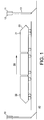
- FIG. 1 there is shown a schematic diagram of a system in accordance with a first embodiment of the invention.
- This embodiment relates to a train service.
- antenna masts 10 comprise: a forward facing sector antenna 11; a rear facing sector antenna 12; and a mast 13.
- Each sector antenna is coupled to a separate, respective access point.
- the sector antennas are directional and the rear facing sector antenna 12 points in the opposite direction along the railway track from the front facing antenna 11.
- the backhaul interface 40 is preferably a fibre optic cable that follows the course of the railway.
- the train 20 has a front modem and antenna 21 (a first communications system) and a rear modem and antenna 22 (a second communications system).
- the first and second communications systems have a common controller and are considered a single mobile terminal. More than two communications systems can be provided, with common control.
- This embodiment may be used to provide wireless backhaul for in-train Wireless LAN services. This is provided by aggregating the capacity available from the existing terrestrial networks, which may currently be supplemented by satellite backhaul when no cellular connection is available.
- the multiple communication systems may each attach to a respective access node, which may be the same or different.
- antennas and modems located at either end of the train can support independent active links to separate access nodes (access points). The capacity of the links can then be aggregated to increase the throughput available when compared to a single link.
- the communication with multiple access nodes will be discussed firstly. Then, further consideration will be given to the way that the multiple communications systems can be configured to achieve improved aggregated throughput.
- FIG. 2 there is depicted a schematic diagram relating to the embodiment for Figure 1 in a first use.
- the train modems will communicate with multiple access nodes using a coordinated or cooperative scheme, such as Cooperative MultiPoint (CoMP) technology.
- CoMP Cooperative MultiPoint
- the front modem can communicate with a rear facing sector via a first link Hi1.
- the rear facing modem of the train can communicate with one or both of two access points via a second link Hs and a third link Hs2.
- a predicted location for the mobile terminal may configure the mobile terminal, the access nodes or both.
- a network entity of the network has a location predication engine. This is used to predict a location for each mobile terminal (which in this embodiment is a train) at a predetermined time.
- the predetermined time is a future time (or range of future times) and therefore the location is only a prediction. This mitigates the effect of high speed movement.
- the prediction is based on the location for the train (or other mobile terminal) at an earlier time, movement data for the train (also at an earlier time) or a combination of the two.
- the predicted location can be used to configure the network, the mobile terminal or both in various ways to improve the quality of communication between the access nodes and the mobile terminal. A number of different ways of achieving this will be discussed below.
- the location need not be limited to an exact location, but it may include, for example, a range of points or areas in space where the vehicular mobile terminal will be passing.
- the prediction would likely be carried out at an access node or centrally at the access network or core network of the cellular network.
- the prediction may be based on current data (such as speed, location, direction, acceleration or similar), historical data (such as recorded data from previous days or the like) as well as on other data (such as current problem with the network, speed limit, accidents or others). Signalling across the can also be used to determine location, such as identifying location by cell or by RF-based position finding.
- the location may be based on one or more of: current location and/or movement data; historic location and/or movement data; time; and other analytics (timetabling information, data about recent journeys or similar).
- Certain types of vehicle such as trains and racing cars follow a specific path. Moreover, their speed along the path may be dictated by established factors. This may further assist in predicted the location of the mobile terminal. The speed can be provisioned by assistance from the vehicle, for example using its GPS, or from history enhanced with a statistical model, such as a Markov model.
- the predicted position of the high speed vehicle could be confirmed by a simple signalling from the vehicle (such as beacon) that is received at an access node.
- the network may decide that at a first time (t1), access nodes A, B and C will start cooperating as the vehicle is predicted to be in the range.
- the network may first check whether the vehicle is actually in that range, for example by checking if node A (that is, the first node into which the vehicle will arrive within the coverage area) has received a beacon signal from the vehicle. If not, the network may then decide to keep using a previous set of co-operating nodes. This checking system could be extended in general to all the network to confirm the correctness of the prediction. In turns, this may reduce risk of loss of coverage, as well as reducing the power consumption of the system.
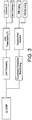
- FIG. 9 there is depicted a schematic diagram of a network element in accordance with a second embodiment of the present invention.
- This network element may represent a separate part of the system and can work together with the embodiment shown in Figure 1 or with other embodiments.
- the network element 90 receives location and/or movement data 91 for a mobile terminal, along the lines discussed above.
- the network element 90 comprises: a location prediction engine 92; a configuration output 93; and a configuration signal 94.
- the location prediction engine 92 predicts a location for the mobile terminal at a predetermined time, based on the received location and/or movement data 91. Then, it passes the predicted location to the configuration output 93, which determines a strategy for coordinated communication with the mobile terminal at the predetermined time, based on its predicted location. Then, the configuration output 93 provides a configuration signal 94, which configures two or more of the plurality of access nodes to effect the coordinated communication.
- the network element 90 may be a specific network entity, it may also form a part of a network entity. Additionally or alternatively, the features of the network element 90 may be split between more than one network entity.
- An approach for using the predicted location can allow the network to decide which set of access nodes (whether the sets are predetermined or adaptively created) will serve the vehicle mobile terminal. This need not require any feedback from the vehicle itself mobile terminal. Feedback may not be reliable at high speeds, limiting the usefulness of such techniques.
- the set of access nodes may be configured to operate cooperatively, for example using CoMP.
- the set of access nodes can therefore be pre-determined based on the predicted location, for example in 2 seconds time. This can be achieved without the mobile terminal suggesting the best transmission points. From the point of view of the moving vehicle, it is equivalent to having a seamless "moving" coordinated or co-operating network always following it.
- the set of the plurality of nodes may be pre-determined or adaptively chosen based on network parameters.
- the system may further include an element to enable or activate the determined set of nodes for communication with the vehicle. The activation may occur at a predicted time. The activation may be dependent upon determining that the vehicle is actually located at the predicted location, as discussed above.
- the predicted location for the mobile terminal can also be used to improve resource allocation.
- Resource for the mobile terminal can be pre-assigned at one or each access node. Additionally or alternatively resources at an access node can be partitioned between multiple mobile terminals based on their predicted location. This may be possible as the base station controller (or equivalent) can predict how many mobile terminals are likely to be required to be served.
- 50% of the resources can be pre-allocated to each of two mobile terminals (such as racing cars during a race). However, if can be determined only one mobile terminal needs to be served then all the resource can be allocated to this. This aspect of resource predetermination of allocation will reduce resource re-allocation and congestion.
- the resources that are allocated may include transmission resources, reception resources and other access node or channel resources.
- the resource allocation may comprise one or more of: a bandwidth allocation (for example in OFDM-based technologies); transmission power allocation; a duty cycle allocation (such as how often transmissions are scheduled to occur); and a power supply allocation (for instance, how much power to provide to the transmitter or receiver).
- Energy consumption particularly of RF components in the network is significant.
- RF transmission causes interference.
- Resource allocation to reduce or minimise energy consumption may be of particular benefit.
- Prediction of the mobile terminal location may be useful in determining how to conserve energy, especially for access nodes along a train track link, which may be used infrequently and which may be closely spaced to ensure connectivity. Possible ways to achieve this include the following.
- Uplink and downlink 3D beams may be steered towards appropriate receive antennas as the Angle of Departure (AOD) may be determined, especially when the mobile terminals is at constant speed.
- AOD Angle of Departure
- the predicted location of the mobile terminal may be used to affect the beam steering at the access nodes. This could be seen as a virtual bean steering, in which a beam "follows" the moving vehicle along its path.
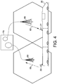
- the train 20 has a front modem 21 and a rear modem 22.
- the rear modem 22 is communicating with a first access node (within a first cell) 50 via a first interface 55.
- the front modem 21 is communicating with a second access node 60 (within a second cell) via a second interface 65.
- the first access node 50 and second access node 60 use backhaul links 70 to interface with the network and each other.
- the coverage of the first and second cells is schematically drawn as hexagonal shapes. Although these are not drawn as tessellating shapes, no significance should be attached to this.
- the first interface 55 is an uplink only interface, whilst the second interface 65 is a downlink only interface.
- this uses time division duplex (TDD) configuration only.
- TDD time division duplex
- a TDD mobile terminal would not simultaneously transmit and receive.
- FDD frequency division duplex
- Single User MIMO Multiple Input Multiple Output
- SISO Single Input Single Output
- MISO Multiple Input Single Output
- each antenna element can be separated from its nearest element by around 4 to 10 times the wavelength the signal, each multipath can be kept independent.
- the wavelength is 0.375 meters (14.75 inch), such that 10 times the wavelength is 3.75 meters.
- Handheld mobile terminals are limited by the form factor, but antenna spacing is less of a constraint on a train. Thus, distributing the antennas along the train may increase spatial diversity. With a typical coach length of approx. 23 meters, at least two mobile terminals can have its each of the 4 antennas separated with good separation.
- the train 20 has a rear communications system 22 comprising four antennas: a first antenna 22a; a second antenna 22b; a third antenna 22c; and a fourth antenna 22d.
- the four antennas are all coupled to the same modem for SU-MIMO to an access node 80.
- a wireless modem for train communication is not constrained by power. Beam tracking for beam-forming may be difficult to achieve at very high speeds, so large antenna beam-width and space/frequency diversity can be exploited to increase capacity. For OFDM-based Radio Access Technologies, such as used on LTE, large sub-carrier spacing may reduce inter-subcarrier interference at high Doppler shifts.
- the access nodes or both may use independent control of the front modem 21 and rear modem 22 of the train 20. Since the front modem 21 and rear modem 22 will be used together to provide an overall service across the train, their operation can be jointly controlled and although the two communication systems may work separately, their joint control may provide improvements. In particular, the aggregate data rate across the communication links between each of the modems and one or more of the access nodes can be controlled, increased or optimised (maximised).
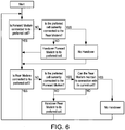
- FIG. 6 there is shown a flowchart for a first mode of operation for the embodiment of Figure 1 .
- the access node to service each of the multiple communications systems is selected to improve the aggregate throughput.
- Figure 6 shows a detailed algorithm, an outline of the reasoning behind this algorithm will be discussed below.
- the communications systems at both ends of the train may not make sense for the communications systems at both ends of the train to be connected to the same access node, as this can result in the access node having to split its capacity between the two ends of the train.
- the received signal quality is likely to be better at one or other end of the train, it therefore makes sense for a given access node to serve only the end of the train where the signal quality is higher. Generally, this will be the end closest to the access point.
- the two ends of the train should normally be served by different access points.
- the situation is straightforward; (with reference to Figure 1 ) the forward end 21 of the train 20 is served by the access point it is heading towards (rear facing sector of the mast ahead of the train) and the rear end 22 of the train 20 is served by the access point that the train is moving away from (forward facing sector of the mast behind the train).
- This situation should be maintained even if the modem at the rear of the train would prefer to handover to the same access point as is being used by the front of the train as the train moves away from the rear mast and towards the forward mast.
- the normal handover mechanism will force the modem at the front of the train to change its connectivity from the rear facing sector to the forward facing sector of that mast.
- the modem at the front of the train can be forced to handover at a given geographical location corresponding to the location of the mast.
- the modem can be informed of its location by a GPS receiver, and the locations of each mast along the route could be stored in an on-board database.
- the modem at the rear of the train can then immediately handover to the rear facing sector if this has not already happened.
- the rear modem will pass the mast, and prefer to connect to the forward facing sector.
- This handover should be executed, and the front modem should be forced to handover to the rear facing sector of the forward mast as soon as this is detected. In this way, the train will be continuously connected to at least one good sector. Again, there may be a period of time when both modems are connected to the same access point and, again, this situation is handled by the scheduler as discussed below.
- Power control is used to maximise throughput to the train, particularly when each modem (communication system) is connected to a different access point. Joint control of the communications systems can be used to effect this.
- the throughput of a given link is a function of the SINR of that link. However, this function can be different for different terminal implementations. Knowing the SINR for a given link does not necessarily mean that the throughput on that link can be accurately estimated.
- the system may thus estimate the combined throughput available to the train.
- the next step is to estimate how a change in the relative transmit powers of the two links will affect the CQIs and hence available throughputs of the links.
- the CQI is not a simple function of the SINR. However, it is possible for the mapping from SINR to CQI to be derived for a given terminal, either by measuring it or from a manufacturer's specification. As it is likely that a limited set or, indeed, only a single terminal type may be used (especially for a train-based system), this is a practical proposition.
- the system can estimate how a given change in SINR will affect both the CQI, and hence the throughput of a link. This estimate may be improved if there is no other co-channel interference affecting the links (perhaps because the spectrum used is dedicated to the application, or is not otherwise used in the area around railway lines).
- the only other source of interference in that case will be the receiver noise floor. It is expected that the signal levels will normally be much higher than the receiver noise floor and it can be assumed, to a good approximation, that the SINR on a link will simply be the ratio of the received powers of the wanted link and interfering link respectively.
- Figure 7 there is shown a flowchart for a second mode of operation of the embodiment of Figure 1 , along the lines discussed above.
- the system will know that a given x dB rise in transmit power on a given link will result in the SINR for that link rising by x dB and the SINR for the other link falling by x dB.
- the system can alter the transmit powers for both links to maximise throughputs.
- This method can be used on both the uplink and downlink, as these are separately power controlled.
- the system can continue to adapt the transmit powers according to the updated CQIs reported following the previous power update. As the system will anyway continually update the transmit powers (because the train is continually moving), this is not a significant issue.
- the scheduler at that access point can ensure maximum throughput by the use of frequency selective scheduling.
- the sector may receive CQI reports from each communication system, and use these to decide which resources to allocate to the front modem, and which to the rear.
- This scheduling strategy is known as "Max C/I" and can be appropriate in this case, as the throughput from both modems is aggregated, and hence fairness mechanisms may not be required.
- the scheduler can apply a fair scheduling algorithm between trains (for example, proportional fair), but a Max C/I algorithm between both modems on the same train.
- the train 100 provides passenger on-board Internet access 105. This is achieved using masts 110, which are 4G LTE or WiMAX pico-cell base stations with self-provisioning relay capabilities. Wireless IP backhaul links 115 may also be used. Further base stations 160 have optical fibre-based backhaul and are shown servicing another train.
- masts 110 which are 4G LTE or WiMAX pico-cell base stations with self-provisioning relay capabilities.
- Wireless IP backhaul links 115 may also be used.
- Further base stations 160 have optical fibre-based backhaul and are shown servicing another train.
- the backhaul links are coupled to an operational control centre 140, which houses a server 130. This may be used for security control, traffic control or both. This also acts as the gateway between the cellular network and the Internet 150.
- Each train is provided with more than one Mobile Radio Terminal (MRTe) 170 (although only one is shown in Figure 10 ). These act as a communications system between the train and the network and provide the on-board Wireless LAN server to passengers 105.
- MRTe Mobile Radio Terminal
- the invention may also be applied to racing cars.
- FIG 11 there is shown a second scenario for operation of the present invention in use.
- Access node base stations are deployed along the perimeter of the race track.
- a typical race circuit can have a coverage area in excess of 3km with sustained throughput of average 50Mbps per car.
- Cooperating sets of base stations are shown for communicating with the multiple racing cars.
Landscapes
- Engineering & Computer Science (AREA)
- Signal Processing (AREA)
- Computer Networks & Wireless Communication (AREA)
- Mobile Radio Communication Systems (AREA)
Claims (15)
- Netzinstanz zum Konfigurieren eines zellularen Kommunikationsnetzes zur Bedienung von Hochgeschwindigkeits-Mobilendgeräten, wobei das zellulare Kommunikationsnetz eine Vielzahl von geografisch verteilten Zugangsknoten umfasst, die zur Kommunikation mit den Mobilendgeräten eingerichtet sind, wobei die Netzinstanz umfasst:Eine Standortvorhersage-Engine, die konfiguriert ist, einen künftigen Standort für ein erstes Mobilendgerät zu einer vorbestimmten Zeit zu vorhersagen; undeine Konfigurationsausgabe, die eingerichtet ist, einen Satz von Zugangsknoten zu konfigurieren, der zwei oder mehr der Vielzahl von Zugangsknoten umfasst, für kooperative Kommunikation des Satzes von Zugangsknoten mit dem ersten Mobilendgerät zur vorbestimmten Zeit auf Basis des vorhergesagten Standorts für das erste Mobilendgerät.
- Netzinstanz nach Anspruch 1, ferner umfassend:Auswahllogik, die konfiguriert ist, zwei oder mehr der Vielzahl von Zugangsknoten, auf Basis des vorhergesagten Standorts für das erste Mobilendgerät, zu selektieren; undwobei die Konfigurationsausgabe eingerichtet ist, die selektierten zwei oder mehr Zugangsknoten für kooperative Kommunikation mit dem ersten Mobilendgerät zu konfigurieren.
- Netzinstanz nach Anspruch 1 oder Anspruch 2, ferner umfassend:Einen Ressourcen-Zuordnungskoordinator, der konfiguriert ist, die Zuordnung von Ressourcen der zwei oder mehr Zugangsknoten für kooperative Kommunikation mit dem ersten Mobilendgerät zur vorbestimmten Zeit, auf Basis des vorhergesagten Standorts für das erste Mobilendgerät zu bestimmen; undwobei die Konfigurationsausgabe eingerichtet ist, die bestimmte Zuordnung von Ressourcen der zwei oder mehreren Zugangsknoten zu konfigurieren.
- Netzinstanz nach Anspruch 3, wobei die für die zwei oder mehr Zugangsknoten bestimmte Zuordnung von Ressourcen eins oder mehrere umfasst von: einer Bandbreitenzuordnung; einer Sendeleistungszuordnung; einer Arbeitszykluszuordnung; und einer Stromversorgungszuordnung.
- Netzinstanz nach Anspruch 3 oder Anspruch 4:Wobei die Standortvorhersage-Engine ferner konfiguriert ist, einen Standort für ein zweites Mobilendgerät zur vorbestimmten Zeit zu vorhersagen; undwobei der Ressourcen-Zuordnungskoordinator ferner konfiguriert ist, die Zuordnung von Ressourcen der zwei oder mehr Zugangsknoten für kooperative Kommunikation mit dem ersten Mobilendgerät und mit dem zweiten Mobilendgerät zur vorbestimmten Zeit, auf Basis des vorhergesagten Standorts für das erste Mobilendgerät und des vorhergesagten Standorts für das zweite Mobilendgerät, zu bestimmen.
- Netzinstanz nach einem der Ansprüche 3 bis 5:Wobei der Ressourcen-Zuordnungskoordinator ferner konfiguriert ist, Aktivierungskennlinien für die Vielzahl von Zugangsknoten, auf Basis des vorhergesagten Standorts für das erste Mobilendgerät, zu erstellen; undwobei die Konfigurationsausgabe eingerichtet ist, zumindest einen Teil der zwei oder mehr Zugangsknoten, auf Basis der erstellten Aktivierungskennlinien, zu aktivieren und/oder zu deaktivieren.
- Netzinstanz nach irgendeinem vorhergehenden Anspruch, ferner umfassend:Antennensteuerungslogik, die konfiguriert ist, Steuerungskonfigurationen für Antennenstrahl der zwei oder mehr Zugangsknoten für kooperative Kommunikation mit dem ersten Mobilendgerät zur vorbestimmten Zeit, auf Basis des vorbestimmten Standorts für das erste Mobilendgerät, zu bestimmen; undwobei die Konfigurationsausgabe eingerichtet ist, die bestimmten Steuerungskonfigurationen für Antennenstrahl der zwei oder mehr Zugangsknoten einzustellen.
- Netzinstanz nach irgendeinem vorhergehenden Anspruch, wobei die Konfigurationsausgabe ferner eingerichtet ist, MIMO-Parameter für die zwei oder mehr Zugangsknoten für kooperative Kommunikation mit dem ersten Mobilendgerät zur vorbestimmten Zeit, auf Basis des vorhergesagten Standorts für das erste Mobilendgerät, zu konfigurieren.
- Netzinstanz nach irgendeinem vorhergehenden Anspruch, wobei das erste Mobilendgerät eine Vielzahl von Kommunikationssystemen umfasst, die Konfigurationsausgabe eingerichtet ist, die zwei oder mehr Zugangsknoten für kooperative Kommunikation mit jedem der Kommunikationssysteme des ersten Mobilendgeräts zur vorbestimmten Zeit, auf Basis des vorhergesagten Standorts für das erste Mobilendgerät, zu konfigurieren.
- Netzinstanz nach Anspruch 9, wobei die Konfigurationsausgabe ferner eingerichtet ist, einen ersten der zwei oder mehr Zugangsknoten für Kommunikation mit einem ersten Kommunikationssystem des ersten Mobilendgeräts zu konfigurieren und einen zweiten der zwei oder mehr Zugangsknoten für Kommunikation mit einem zweiten Kommunikationssystem des ersten Mobilendgeräts zu konfigurieren, wobei die Kommunikation mit den ersten und zweiten Kommunikationssystemen koordiniert ist.
- Netzinstanz nach irgendeinem vorhergehenden Anspruch, wobei die Standortvorhersage-Engine konfiguriert ist, einen Standort für das erste Mobilendgerät zur vorbestimmten Zeit, auf Basis von einem oder mehreren von Folgenden zu vorhersagen: aktuellen Standortdaten für das erste Mobilendgerät; aktuellen Bewegungsdaten für das erste Mobilendgerät; einem Standort für das erste Mobilendgerät zu einer Zeit vor der vorbestimmten Zeit; einer Geschwindigkeit für das erste Mobilendgerät zur Zeit vor der vorbestimmten Zeit; einer Richtung für das erste Mobilendgerät zur Zeit vor der vorbestimmten Zeit; und einer aktuellen Zeit.
- Netzinstanz nach irgendeinem vorhergehenden Anspruch, wobei die Standortvorhersage-Engine konfiguriert ist, einen Standort für das erste Mobilendgerät zur vorbestimmten Zeit, auf Basis einer vorbestimmten Fahrroute für das erste Mobilendgerät, zu vorhersagen.
- Netzinstanz nach irgendeinem vorhergehenden Anspruch, wobei das zellulare Kommunikationsnetz eins oder mehrere von Folgenden umfasst: ein drahtloses lokales Netz; ein drahtloses Weitverkehrsnetz; und ein mobiles Telekommunikationsnetz.
- Verfahren zum Konfigurieren eines zellularen Kommunikationsnetzes zur Bedienung von Hochgeschwindigkeits-Mobilendgeräten, das eine Vielzahl von geografisch verteilten Zugangsknoten umfasst, die zur Kommunikation mit den Mobilendgeräten eingerichtet sind, wobei das Verfahren umfasst:Vorhersagen eines künftigen Standorts für ein erstes Mobilendgerät zu einer vorbestimmten Zeit; undKonfigurieren eines Satzes von Zugangsknoten, der zwei oder mehr der Vielzahl von Zugangsknoten umfasst, für kooperative Kommunikation des Satzes von Zugangsknoten mit dem ersten Mobilendgerät zur vorbestimmten Zeit, auf Basis des vorhergesagten Standorts für das erste Mobilendgerät.
- Computerprogramm, das eingerichtet ist, das Verfahren von Anspruch 14, wenn von einem Prozessor betrieben, auszuführen.
Applications Claiming Priority (2)
| Application Number | Priority Date | Filing Date | Title |
|---|---|---|---|
| GB1318818.0A GB2522603A (en) | 2013-10-24 | 2013-10-24 | High speed communication for vehicles |
| PCT/GB2014/053180 WO2015059494A1 (en) | 2013-10-24 | 2014-10-24 | High speed communication for vehicles |
Publications (2)
| Publication Number | Publication Date |
|---|---|
| EP3061291A1 EP3061291A1 (de) | 2016-08-31 |
| EP3061291B1 true EP3061291B1 (de) | 2020-06-10 |
Family
ID=49767110
Family Applications (1)
| Application Number | Title | Priority Date | Filing Date |
|---|---|---|---|
| EP14790280.3A Active EP3061291B1 (de) | 2013-10-24 | 2014-10-24 | Hochgeschwindigkeitskommunikation für fahrzeuge |
Country Status (4)
| Country | Link |
|---|---|
| US (1) | US11349615B2 (de) |
| EP (1) | EP3061291B1 (de) |
| GB (1) | GB2522603A (de) |
| WO (1) | WO2015059494A1 (de) |
Families Citing this family (33)
| Publication number | Priority date | Publication date | Assignee | Title |
|---|---|---|---|---|
| FR3025480B1 (fr) * | 2014-09-04 | 2016-12-23 | Alstom Transp Tech | Infrastructure de radiocommunication pour un systeme de signalisation ferroviaire du type cbtc |
| CN104853393A (zh) * | 2015-04-29 | 2015-08-19 | 努比亚技术有限公司 | 移动终端切换网络的方法和装置 |
| TWI591975B (zh) * | 2015-12-23 | 2017-07-11 | 財團法人工業技術研究院 | 合作式多點傳輸方法、控制節點以及無線通訊裝置 |
| KR101881166B1 (ko) * | 2016-05-17 | 2018-07-23 | 한국전자통신연구원 | 이동무선백홀 네트워크의 빔 포밍 통신 장치 및 방법 |
| WO2018060538A1 (en) * | 2016-09-27 | 2018-04-05 | Nokia Technologies Oy | Multi-cell allocation |
| EP3379737B1 (de) * | 2017-03-23 | 2020-09-23 | Legic Identsystems AG | System und verfahren zur bestimmung von positionsinformationen für einen mobilfunksender |
| GB2591633A (en) * | 2017-06-30 | 2021-08-04 | First Rail Holdings Ltd | Communicating with a mobile device |
| GB2563932B (en) * | 2017-06-30 | 2021-04-14 | First Rail Holdings Ltd | Communicating with a mobile device |
| CN109874111B (zh) | 2017-12-05 | 2022-04-12 | 中兴通讯股份有限公司 | 调度方法、发送信息的方法、装置及存储介质 |
| US10638482B2 (en) * | 2017-12-15 | 2020-04-28 | Qualcomm Incorporated | Methods and apparatuses for dynamic beam pair determination |
| CN111903063B (zh) | 2018-03-19 | 2022-08-12 | 皮沃塔尔卡姆瓦雷股份有限公司 | 传送无线信号通过物理屏障 |
| US10225760B1 (en) | 2018-03-19 | 2019-03-05 | Pivotal Commware, Inc. | Employing correlation measurements to remotely evaluate beam forming antennas |
| KR102460324B1 (ko) * | 2018-04-17 | 2022-10-28 | 삼성전자 주식회사 | 무선 통신 시스템에서 단말의 이동성을 지원하는 방법 및 장치 |
| US10862545B2 (en) * | 2018-07-30 | 2020-12-08 | Pivotal Commware, Inc. | Distributed antenna networks for wireless communication by wireless devices |
| US10326203B1 (en) | 2018-09-19 | 2019-06-18 | Pivotal Commware, Inc. | Surface scattering antenna systems with reflector or lens |
| US10522897B1 (en) | 2019-02-05 | 2019-12-31 | Pivotal Commware, Inc. | Thermal compensation for a holographic beam forming antenna |
| US10468767B1 (en) | 2019-02-20 | 2019-11-05 | Pivotal Commware, Inc. | Switchable patch antenna |
| US10734736B1 (en) | 2020-01-03 | 2020-08-04 | Pivotal Commware, Inc. | Dual polarization patch antenna system |
| US11069975B1 (en) | 2020-04-13 | 2021-07-20 | Pivotal Commware, Inc. | Aimable beam antenna system |
| KR102872581B1 (ko) | 2020-05-27 | 2025-10-17 | 피보탈 컴웨어 인코포레이티드 | 5g 무선 네트워크들을 위한 rf 신호 중계기 디바이스 관리 |
| US11026055B1 (en) | 2020-08-03 | 2021-06-01 | Pivotal Commware, Inc. | Wireless communication network management for user devices based on real time mapping |
| WO2022056024A1 (en) | 2020-09-08 | 2022-03-17 | Pivotal Commware, Inc. | Installation and activation of rf communication devices for wireless networks |
| RU2753772C1 (ru) * | 2020-12-18 | 2021-08-23 | Ооо "Док" | Способы и система обеспечения высокоскоростной связи на высокоскоростной железной дороге |
| AU2022208705A1 (en) | 2021-01-15 | 2023-08-31 | Pivotal Commware, Inc. | Installation of repeaters for a millimeter wave communications network |
| EP4285628A4 (de) | 2021-01-26 | 2024-12-18 | Pivotal Commware, Inc. | Intelligente repeater-systeme |
| US11451287B1 (en) | 2021-03-16 | 2022-09-20 | Pivotal Commware, Inc. | Multipath filtering for wireless RF signals |
| AU2022307056A1 (en) | 2021-07-07 | 2024-02-15 | Pivotal Commware, Inc. | Multipath repeater systems |
| CN115707047A (zh) * | 2021-08-06 | 2023-02-17 | 华为技术有限公司 | 一种通信方法及装置 |
| WO2023062495A1 (en) * | 2021-10-11 | 2023-04-20 | Telefonaktiebolaget Lm Ericsson (Publ) | Resource allocation using vehicle maneuver prediction |
| WO2023076405A1 (en) | 2021-10-26 | 2023-05-04 | Pivotal Commware, Inc. | Rf absorbing structures |
| JP2025512562A (ja) | 2022-04-18 | 2025-04-17 | ピヴォタル コムウェア インコーポレイテッド | 全球測位衛星システムを備える時分割複信リピータタイミングリカバリ |
| EP4346310A1 (de) * | 2022-09-29 | 2024-04-03 | Vodafone Group Services Limited | Verbesserte basisstationseffizienz |
| US20240267797A1 (en) * | 2023-02-03 | 2024-08-08 | T-Mobile Usa, Inc. | Pre-termination handover in edge processing |
Family Cites Families (11)
| Publication number | Priority date | Publication date | Assignee | Title |
|---|---|---|---|---|
| TW595857U (en) * | 2001-11-29 | 2004-06-21 | Us | 091219345 |
| US20060068822A1 (en) * | 2004-09-29 | 2006-03-30 | Amit Kalhan | Method and apparatus for implementation of ad hoc mesh network |
| AU2006349035B2 (en) * | 2006-10-05 | 2011-02-17 | Telefonaktiebolaget L M Ericsson (Publ) | MIMO mode selection at handover |
| US20080181180A1 (en) * | 2007-01-31 | 2008-07-31 | Jeyhan Karaoguz | Efficient network hand-off utilizing stored beam-forming information |
| US8422460B2 (en) | 2009-04-06 | 2013-04-16 | Robert Bosch Gmbh | Method for performing proactive wireless communication handoffs using a mobile client's route information |
| US10172114B2 (en) * | 2009-12-11 | 2019-01-01 | Nokia Technologies Oy | Apparatus and associated methods for determining available channels based on predicted movement |
| KR101728371B1 (ko) | 2011-01-07 | 2017-04-19 | 삼성전자주식회사 | 분산 안테나 시스템에서 고속의 이동 단말을 지원하기 위한 방법 및 장치 |
| US20120182935A1 (en) * | 2011-01-14 | 2012-07-19 | Cisco Technology, Inc. | System and method for packet distribution in a vehicular network environment |
| EP2582192A1 (de) | 2011-10-12 | 2013-04-17 | Alcatel Lucent | Vorrichtungen, Verfahren und Computerprogramme für einen mobilen Sender-Empfänger und für einen Basisstations-Sender-Empfänger |
| US9313766B2 (en) * | 2012-06-01 | 2016-04-12 | Interdigital Patent Holdings, Inc. | Bandwidth management (BWM) operation with opportunistic networks |
| CN105009641A (zh) * | 2012-10-05 | 2015-10-28 | 瑞典爱立信有限公司 | 蜂窝网络中的干扰减轻 |
-
2013
- 2013-10-24 GB GB1318818.0A patent/GB2522603A/en not_active Withdrawn
-
2014
- 2014-10-24 EP EP14790280.3A patent/EP3061291B1/de active Active
- 2014-10-24 US US15/031,497 patent/US11349615B2/en active Active
- 2014-10-24 WO PCT/GB2014/053180 patent/WO2015059494A1/en not_active Ceased
Non-Patent Citations (1)
| Title |
|---|
| None * |
Also Published As
| Publication number | Publication date |
|---|---|
| US11349615B2 (en) | 2022-05-31 |
| GB2522603A (en) | 2015-08-05 |
| EP3061291A1 (de) | 2016-08-31 |
| WO2015059494A1 (en) | 2015-04-30 |
| US20160241367A1 (en) | 2016-08-18 |
| GB201318818D0 (en) | 2013-12-11 |
Similar Documents
| Publication | Publication Date | Title |
|---|---|---|
| US11349615B2 (en) | High speed communication for vehicles | |
| US20160269964A1 (en) | Increasing cellular communication data throughput | |
| US10069544B2 (en) | Wireless communication system for high-speed moving object that moves along fixed route | |
| Schwarz et al. | Society in motion: Challenges for LTE and beyond mobile communications | |
| US12177691B2 (en) | Central cloud server and edge devices assisted high speed low-latency wireless connectivity | |
| Kela et al. | Borderless mobility in 5G outdoor ultra-dense networks | |
| JP6243181B2 (ja) | 無線通信システム、無線移動局、及び無線基地局 | |
| CN111108789A (zh) | 通信设备和通信方法 | |
| RU2015116647A (ru) | Подавление помех гетерогенным сетям от мобильного ретрансляционного узла | |
| CN102970067B (zh) | 一种用于实现连续的宽带通信的方法 | |
| Luo et al. | Reliable broadband wireless communication for high speed trains using baseband cloud | |
| KR101175612B1 (ko) | 적응성 빔 기반 통신시스템 및 그 스케줄링 방법 | |
| KR102472107B1 (ko) | 능동적으로 사용되는 스펙트럼 내에서의 간섭을 완화시키기 위한 시스템 및 방법 | |
| EP3253126B1 (de) | Verfahren zur planung von übertragungsressourcen in einem mobilkommunikationssystem und basisstation, relaisstation und benutzergerätestation zur verwendung in dem verfahren | |
| US20150103778A1 (en) | Cooperation multi-input multi-output transmitting or receiving method | |
| Mignardi et al. | Optimizing beam selection and resource allocation in UAV-aided vehicular networks | |
| Botsov et al. | Location-based resource allocation for mobile D2D communications in multicell deployments | |
| KR20120080324A (ko) | 분산 안테나 시스템에서 고속의 이동 단말을 지원하기 위한 방법 및 장치 | |
| KR101415194B1 (ko) | 광대역 무선통신 시스템에서 이동 중계기를 위한 자원할당방법 및 장치 | |
| KR20180009644A (ko) | 이동무선백홀 네트워크에서의 고속 이동체 단말 및 그의 통신 방법 | |
| JP7562693B2 (ja) | 同期されたモバイルデバイス間で通信する方法、記憶媒体及びモバイルデバイス | |
| CHIHI et al. | Congestion Control investigation into 5G V2V | |
| CN120090744A (zh) | 空天地一体化网络下高铁隧道毫米波通信场景的动态传输优化方法 | |
| KR20150043968A (ko) | 협력 다중입력다중출력 송수신 방법 |
Legal Events
| Date | Code | Title | Description |
|---|---|---|---|
| PUAI | Public reference made under article 153(3) epc to a published international application that has entered the european phase |
Free format text: ORIGINAL CODE: 0009012 |
|
| 17P | Request for examination filed |
Effective date: 20160518 |
|
| AK | Designated contracting states |
Kind code of ref document: A1 Designated state(s): AL AT BE BG CH CY CZ DE DK EE ES FI FR GB GR HR HU IE IS IT LI LT LU LV MC MK MT NL NO PL PT RO RS SE SI SK SM TR |
|
| AX | Request for extension of the european patent |
Extension state: BA ME |
|
| STAA | Information on the status of an ep patent application or granted ep patent |
Free format text: STATUS: REQUEST FOR EXAMINATION WAS MADE |
|
| DAX | Request for extension of the european patent (deleted) | ||
| STAA | Information on the status of an ep patent application or granted ep patent |
Free format text: STATUS: EXAMINATION IS IN PROGRESS |
|
| 17Q | First examination report despatched |
Effective date: 20181105 |
|
| RIC1 | Information provided on ipc code assigned before grant |
Ipc: H04W 72/04 20090101ALI20190405BHEP Ipc: H04B 7/024 20170101ALI20190405BHEP Ipc: H04W 64/00 20090101AFI20190405BHEP |
|
| GRAP | Despatch of communication of intention to grant a patent |
Free format text: ORIGINAL CODE: EPIDOSNIGR1 |
|
| STAA | Information on the status of an ep patent application or granted ep patent |
Free format text: STATUS: GRANT OF PATENT IS INTENDED |
|
| INTG | Intention to grant announced |
Effective date: 20190517 |
|
| GRAJ | Information related to disapproval of communication of intention to grant by the applicant or resumption of examination proceedings by the epo deleted |
Free format text: ORIGINAL CODE: EPIDOSDIGR1 |
|
| STAA | Information on the status of an ep patent application or granted ep patent |
Free format text: STATUS: EXAMINATION IS IN PROGRESS |
|
| GRAP | Despatch of communication of intention to grant a patent |
Free format text: ORIGINAL CODE: EPIDOSNIGR1 |
|
| STAA | Information on the status of an ep patent application or granted ep patent |
Free format text: STATUS: GRANT OF PATENT IS INTENDED |
|
| INTC | Intention to grant announced (deleted) | ||
| INTG | Intention to grant announced |
Effective date: 20191001 |
|
| GRAJ | Information related to disapproval of communication of intention to grant by the applicant or resumption of examination proceedings by the epo deleted |
Free format text: ORIGINAL CODE: EPIDOSDIGR1 |
|
| STAA | Information on the status of an ep patent application or granted ep patent |
Free format text: STATUS: EXAMINATION IS IN PROGRESS |
|
| GRAP | Despatch of communication of intention to grant a patent |
Free format text: ORIGINAL CODE: EPIDOSNIGR1 |
|
| STAA | Information on the status of an ep patent application or granted ep patent |
Free format text: STATUS: GRANT OF PATENT IS INTENDED |
|
| INTC | Intention to grant announced (deleted) | ||
| INTG | Intention to grant announced |
Effective date: 20200226 |
|
| GRAS | Grant fee paid |
Free format text: ORIGINAL CODE: EPIDOSNIGR3 |
|
| GRAA | (expected) grant |
Free format text: ORIGINAL CODE: 0009210 |
|
| STAA | Information on the status of an ep patent application or granted ep patent |
Free format text: STATUS: THE PATENT HAS BEEN GRANTED |
|
| AK | Designated contracting states |
Kind code of ref document: B1 Designated state(s): AL AT BE BG CH CY CZ DE DK EE ES FI FR GB GR HR HU IE IS IT LI LT LU LV MC MK MT NL NO PL PT RO RS SE SI SK SM TR |
|
| REG | Reference to a national code |
Ref country code: GB Ref legal event code: FG4D |
|
| REG | Reference to a national code |
Ref country code: CH Ref legal event code: EP Ref country code: AT Ref legal event code: REF Ref document number: 1280186 Country of ref document: AT Kind code of ref document: T Effective date: 20200615 |
|
| REG | Reference to a national code |
Ref country code: DE Ref legal event code: R096 Ref document number: 602014066507 Country of ref document: DE |
|
| REG | Reference to a national code |
Ref country code: IE Ref legal event code: FG4D |
|
| REG | Reference to a national code |
Ref country code: LT Ref legal event code: MG4D |
|
| PG25 | Lapsed in a contracting state [announced via postgrant information from national office to epo] |
Ref country code: FI Free format text: LAPSE BECAUSE OF FAILURE TO SUBMIT A TRANSLATION OF THE DESCRIPTION OR TO PAY THE FEE WITHIN THE PRESCRIBED TIME-LIMIT Effective date: 20200610 Ref country code: NO Free format text: LAPSE BECAUSE OF FAILURE TO SUBMIT A TRANSLATION OF THE DESCRIPTION OR TO PAY THE FEE WITHIN THE PRESCRIBED TIME-LIMIT Effective date: 20200910 Ref country code: SE Free format text: LAPSE BECAUSE OF FAILURE TO SUBMIT A TRANSLATION OF THE DESCRIPTION OR TO PAY THE FEE WITHIN THE PRESCRIBED TIME-LIMIT Effective date: 20200610 Ref country code: LT Free format text: LAPSE BECAUSE OF FAILURE TO SUBMIT A TRANSLATION OF THE DESCRIPTION OR TO PAY THE FEE WITHIN THE PRESCRIBED TIME-LIMIT Effective date: 20200610 Ref country code: GR Free format text: LAPSE BECAUSE OF FAILURE TO SUBMIT A TRANSLATION OF THE DESCRIPTION OR TO PAY THE FEE WITHIN THE PRESCRIBED TIME-LIMIT Effective date: 20200911 |
|
| REG | Reference to a national code |
Ref country code: NL Ref legal event code: MP Effective date: 20200610 |
|
| PG25 | Lapsed in a contracting state [announced via postgrant information from national office to epo] |
Ref country code: BG Free format text: LAPSE BECAUSE OF FAILURE TO SUBMIT A TRANSLATION OF THE DESCRIPTION OR TO PAY THE FEE WITHIN THE PRESCRIBED TIME-LIMIT Effective date: 20200910 Ref country code: LV Free format text: LAPSE BECAUSE OF FAILURE TO SUBMIT A TRANSLATION OF THE DESCRIPTION OR TO PAY THE FEE WITHIN THE PRESCRIBED TIME-LIMIT Effective date: 20200610 Ref country code: HR Free format text: LAPSE BECAUSE OF FAILURE TO SUBMIT A TRANSLATION OF THE DESCRIPTION OR TO PAY THE FEE WITHIN THE PRESCRIBED TIME-LIMIT Effective date: 20200610 Ref country code: RS Free format text: LAPSE BECAUSE OF FAILURE TO SUBMIT A TRANSLATION OF THE DESCRIPTION OR TO PAY THE FEE WITHIN THE PRESCRIBED TIME-LIMIT Effective date: 20200610 |
|
| REG | Reference to a national code |
Ref country code: AT Ref legal event code: MK05 Ref document number: 1280186 Country of ref document: AT Kind code of ref document: T Effective date: 20200610 |
|
| PG25 | Lapsed in a contracting state [announced via postgrant information from national office to epo] |
Ref country code: NL Free format text: LAPSE BECAUSE OF FAILURE TO SUBMIT A TRANSLATION OF THE DESCRIPTION OR TO PAY THE FEE WITHIN THE PRESCRIBED TIME-LIMIT Effective date: 20200610 Ref country code: AL Free format text: LAPSE BECAUSE OF FAILURE TO SUBMIT A TRANSLATION OF THE DESCRIPTION OR TO PAY THE FEE WITHIN THE PRESCRIBED TIME-LIMIT Effective date: 20200610 |
|
| PG25 | Lapsed in a contracting state [announced via postgrant information from national office to epo] |
Ref country code: EE Free format text: LAPSE BECAUSE OF FAILURE TO SUBMIT A TRANSLATION OF THE DESCRIPTION OR TO PAY THE FEE WITHIN THE PRESCRIBED TIME-LIMIT Effective date: 20200610 Ref country code: SM Free format text: LAPSE BECAUSE OF FAILURE TO SUBMIT A TRANSLATION OF THE DESCRIPTION OR TO PAY THE FEE WITHIN THE PRESCRIBED TIME-LIMIT Effective date: 20200610 Ref country code: AT Free format text: LAPSE BECAUSE OF FAILURE TO SUBMIT A TRANSLATION OF THE DESCRIPTION OR TO PAY THE FEE WITHIN THE PRESCRIBED TIME-LIMIT Effective date: 20200610 Ref country code: IT Free format text: LAPSE BECAUSE OF FAILURE TO SUBMIT A TRANSLATION OF THE DESCRIPTION OR TO PAY THE FEE WITHIN THE PRESCRIBED TIME-LIMIT Effective date: 20200610 Ref country code: PT Free format text: LAPSE BECAUSE OF FAILURE TO SUBMIT A TRANSLATION OF THE DESCRIPTION OR TO PAY THE FEE WITHIN THE PRESCRIBED TIME-LIMIT Effective date: 20201012 Ref country code: RO Free format text: LAPSE BECAUSE OF FAILURE TO SUBMIT A TRANSLATION OF THE DESCRIPTION OR TO PAY THE FEE WITHIN THE PRESCRIBED TIME-LIMIT Effective date: 20200610 Ref country code: CZ Free format text: LAPSE BECAUSE OF FAILURE TO SUBMIT A TRANSLATION OF THE DESCRIPTION OR TO PAY THE FEE WITHIN THE PRESCRIBED TIME-LIMIT Effective date: 20200610 Ref country code: ES Free format text: LAPSE BECAUSE OF FAILURE TO SUBMIT A TRANSLATION OF THE DESCRIPTION OR TO PAY THE FEE WITHIN THE PRESCRIBED TIME-LIMIT Effective date: 20200610 |
|
| PG25 | Lapsed in a contracting state [announced via postgrant information from national office to epo] |
Ref country code: PL Free format text: LAPSE BECAUSE OF FAILURE TO SUBMIT A TRANSLATION OF THE DESCRIPTION OR TO PAY THE FEE WITHIN THE PRESCRIBED TIME-LIMIT Effective date: 20200610 Ref country code: SK Free format text: LAPSE BECAUSE OF FAILURE TO SUBMIT A TRANSLATION OF THE DESCRIPTION OR TO PAY THE FEE WITHIN THE PRESCRIBED TIME-LIMIT Effective date: 20200610 Ref country code: IS Free format text: LAPSE BECAUSE OF FAILURE TO SUBMIT A TRANSLATION OF THE DESCRIPTION OR TO PAY THE FEE WITHIN THE PRESCRIBED TIME-LIMIT Effective date: 20201010 |
|
| REG | Reference to a national code |
Ref country code: DE Ref legal event code: R097 Ref document number: 602014066507 Country of ref document: DE |
|
| PLBE | No opposition filed within time limit |
Free format text: ORIGINAL CODE: 0009261 |
|
| STAA | Information on the status of an ep patent application or granted ep patent |
Free format text: STATUS: NO OPPOSITION FILED WITHIN TIME LIMIT |
|
| PG25 | Lapsed in a contracting state [announced via postgrant information from national office to epo] |
Ref country code: DK Free format text: LAPSE BECAUSE OF FAILURE TO SUBMIT A TRANSLATION OF THE DESCRIPTION OR TO PAY THE FEE WITHIN THE PRESCRIBED TIME-LIMIT Effective date: 20200610 |
|
| 26N | No opposition filed |
Effective date: 20210311 |
|
| PG25 | Lapsed in a contracting state [announced via postgrant information from national office to epo] |
Ref country code: SI Free format text: LAPSE BECAUSE OF FAILURE TO SUBMIT A TRANSLATION OF THE DESCRIPTION OR TO PAY THE FEE WITHIN THE PRESCRIBED TIME-LIMIT Effective date: 20200610 |
|
| REG | Reference to a national code |
Ref country code: CH Ref legal event code: PL |
|
| PG25 | Lapsed in a contracting state [announced via postgrant information from national office to epo] |
Ref country code: MC Free format text: LAPSE BECAUSE OF FAILURE TO SUBMIT A TRANSLATION OF THE DESCRIPTION OR TO PAY THE FEE WITHIN THE PRESCRIBED TIME-LIMIT Effective date: 20200610 Ref country code: LU Free format text: LAPSE BECAUSE OF NON-PAYMENT OF DUE FEES Effective date: 20201024 |
|
| REG | Reference to a national code |
Ref country code: BE Ref legal event code: MM Effective date: 20201031 |
|
| PG25 | Lapsed in a contracting state [announced via postgrant information from national office to epo] |
Ref country code: LI Free format text: LAPSE BECAUSE OF NON-PAYMENT OF DUE FEES Effective date: 20201031 Ref country code: CH Free format text: LAPSE BECAUSE OF NON-PAYMENT OF DUE FEES Effective date: 20201031 Ref country code: BE Free format text: LAPSE BECAUSE OF NON-PAYMENT OF DUE FEES Effective date: 20201031 |
|
| PG25 | Lapsed in a contracting state [announced via postgrant information from national office to epo] |
Ref country code: IE Free format text: LAPSE BECAUSE OF NON-PAYMENT OF DUE FEES Effective date: 20201024 |
|
| PG25 | Lapsed in a contracting state [announced via postgrant information from national office to epo] |
Ref country code: TR Free format text: LAPSE BECAUSE OF FAILURE TO SUBMIT A TRANSLATION OF THE DESCRIPTION OR TO PAY THE FEE WITHIN THE PRESCRIBED TIME-LIMIT Effective date: 20200610 Ref country code: MT Free format text: LAPSE BECAUSE OF FAILURE TO SUBMIT A TRANSLATION OF THE DESCRIPTION OR TO PAY THE FEE WITHIN THE PRESCRIBED TIME-LIMIT Effective date: 20200610 Ref country code: CY Free format text: LAPSE BECAUSE OF FAILURE TO SUBMIT A TRANSLATION OF THE DESCRIPTION OR TO PAY THE FEE WITHIN THE PRESCRIBED TIME-LIMIT Effective date: 20200610 |
|
| PG25 | Lapsed in a contracting state [announced via postgrant information from national office to epo] |
Ref country code: MK Free format text: LAPSE BECAUSE OF FAILURE TO SUBMIT A TRANSLATION OF THE DESCRIPTION OR TO PAY THE FEE WITHIN THE PRESCRIBED TIME-LIMIT Effective date: 20200610 |
|
| PGFP | Annual fee paid to national office [announced via postgrant information from national office to epo] |
Ref country code: DE Payment date: 20251021 Year of fee payment: 12 |
|
| PGFP | Annual fee paid to national office [announced via postgrant information from national office to epo] |
Ref country code: GB Payment date: 20251022 Year of fee payment: 12 |
|
| PGFP | Annual fee paid to national office [announced via postgrant information from national office to epo] |
Ref country code: FR Payment date: 20251030 Year of fee payment: 12 |