EP3061237B1 - Système et procédé de mise au point automatique sur la base de données statistiques - Google Patents
Système et procédé de mise au point automatique sur la base de données statistiques Download PDFInfo
- Publication number
- EP3061237B1 EP3061237B1 EP14902569.4A EP14902569A EP3061237B1 EP 3061237 B1 EP3061237 B1 EP 3061237B1 EP 14902569 A EP14902569 A EP 14902569A EP 3061237 B1 EP3061237 B1 EP 3061237B1
- Authority
- EP
- European Patent Office
- Prior art keywords
- image
- lens
- focusing
- camera
- image focusing
- Prior art date
- Legal status (The legal status is an assumption and is not a legal conclusion. Google has not performed a legal analysis and makes no representation as to the accuracy of the status listed.)
- Not-in-force
Links
Images


Classifications
-
- H—ELECTRICITY
- H04—ELECTRIC COMMUNICATION TECHNIQUE
- H04N—PICTORIAL COMMUNICATION, e.g. TELEVISION
- H04N23/00—Cameras or camera modules comprising electronic image sensors; Control thereof
- H04N23/60—Control of cameras or camera modules
- H04N23/67—Focus control based on electronic image sensor signals
-
- G—PHYSICS
- G02—OPTICS
- G02B—OPTICAL ELEMENTS, SYSTEMS OR APPARATUS
- G02B7/00—Mountings, adjusting means, or light-tight connections, for optical elements
- G02B7/02—Mountings, adjusting means, or light-tight connections, for optical elements for lenses
- G02B7/04—Mountings, adjusting means, or light-tight connections, for optical elements for lenses with mechanism for focusing or varying magnification
- G02B7/09—Mountings, adjusting means, or light-tight connections, for optical elements for lenses with mechanism for focusing or varying magnification adapted for automatic focusing or varying magnification
Definitions
- the disclosed examples and embodiments relate generally to imaging systems and methods, and more particularly, but not exclusively, to a system and method for automatic focusing by selecting a set of lens focusing windows and calculating a weighted window evaluation value for the set of lens focusing windows based on statistic data.
- imaging devices are equipped with functionalities of automatic focusing, where a focusing process is performed without any intervention by an operator of a device.
- Typical image devices include cameras, video recorders and other devices with image taking or recording capabilities, such as smart mobile phones.
- a first step is to focus on an object being photographed.
- Some cameras are equipped with automatic focusing functionality.
- one image frame can be divided into three image regions: main imaging region, secondary imaging region and background imaging region.
- the main purpose for focusing is to make the image within the main imaging region as clear as possible.
- a lens In a focusing process, a lens can be regarded as a convex lens. For a certain focus value of a zoom lens or for a fixed-focus lens, a focus distance is fixed.
- the space depths for its main imaging region, its secondary imaging region and its background region are different, i.e. the object distances for those three are different. Therefore, at a specific time and with a certain focus distance, the image distance can only be adjusted to satisfy Equation 1 with respect to the image distance of only one region.
- the main imaging region In order to obtain a picture with a clear main imaging region, the main imaging region should be correctly found and should be precisely located within a proper dimensioned focusing window, so as to let it focus precisely.
- center selection approach is to take a small region of M ⁇ N pixels in the center of an image frame as a focusing window.
- Multi-region selection approach is to take a plurality of representative regions as image focusing windows, e.g. regions with M ⁇ N pixels centered with four dividing points along the horizontal axis or the vertical axis.
- Multi-region selection approach can also take regions with M ⁇ N pixels centered with four dividing points along the two diagonal lines as image focusing windows.
- the main imaging region does not always falls into one of the above described regions. In some circumstances, the main imaging region is located in the above described regions and the purpose of precise focusing can be achieved in those circumstances. However, when the main imaging region is not within the above described regions, the above described approaches for focusing window are unable to guaranty a picture with clear main imaging region. Second, when the area of a focusing window is greater the main imaging region, the existing approaches not only increase the amount of calculations, they can also deteriorate the final results of focusing. The reason for the deterioration is because they cause the focusing evaluation curves not sharp enough at the transition or joint places.
- US2008/316352 A1 describes a focusing apparatus applied in an image recording system.
- the focusing apparatus of the invention includes an evaluating unit and a control module.
- the evaluating unit can generate a plurality of focus values in accordance with an image sensed by a sensor.
- the control module can calculate a weight focus value in accordance with the focus values, and selectively generates a control signal based on the weight focus value and a depth of focus table, so as to control the movement of a lens.
- US 2003/063212 A1 describes a camera that includes: an image-capturing element that captures a subject image through a photographic lens having a focusing lens; an evaluation value calculation unit that calculates focus evaluation values at a plurality of lens positions assumed by the focusing lens based upon an image-capturing signal output by the image-capturing element; a weighting unit that weights the focus evaluation values calculated by the evaluation value calculation unit in correspondence to the lens positions of the focusing lens assumed when the focus evaluation values are calculated respectively; and a focusing operation unit that performs a focusing operation for the photographic lens based upon the weighted focus evaluation values.
- EP 1 737 216 A1 describes an object determining device of the invention for selecting a target face for processing from plural faces in an image includes face detecting means that detects faces from an image; face information recording means that records the face detected in the past by the face detecting means and the detection history relating to this detection as associated with each other; and face selecting means that selects a target face for processing, from the faces included in the image based upon the detection history.
- the object determining device includes face information updating means that, in a case where the face detected by the face detecting means is not present in the face information recording means, newly registers the face, and in a case where the face is present, updates the face information.
- the present invention relates to a method for manufacturing according to independent claim 1. Preferred embodiments are described in the dependent claims.
- the method is for manufacturing a camera capable of coupling with a lens and being capable of automatic focusing an image in a main image region, the method comprising:
- Pa represents the object distance between a main imaging object A and a lens 112
- Pb represents the object distance between a background object B and the lens 112
- Pa' represents the image distance between the lens 112 and an image A' formed by the main imaging object A
- Pb' represents the image distance between the lens 112 and an image B' formed on a sensor by the background imaging object B
- f represents the focus distance of the lens 112.
- ME(I) E I MN
- E(I) is a general focusing evaluation function
- I represents an image being processed
- MN refers to a total number of pixels within the area of the image frame.
- Equation (4) ME(I) has the same properties as E(I), which properties include:
- FIG. 1 illustrates a imaging scenario within a focusing window
- Equation (4) can be further deduced as follows:
- S(A') represents the area of the main imaging region A', i.e. the number of pixels in the main imaging region A'
- S(B') represents the area of the background region B', i.e. the number of pixels in the background imaging region B'
- p represents the ratio of the main imaging region A's to the whole area of the M ⁇ N image defined by the focusing window.
- the average evaluation function ME(I) consists of a weighted pixel average function for both main imaging region function and background imaging region function.
- the weight values are directly proportional to the number of pixels within respective regions.
- the weight for the main imaging region and the weight for the background can be mutually exclusive.
- the relationships among the averaging function for all image pixels, the averaging evaluation function for the main imaging region, the averaging evaluation function for the background imaging region are illustrated in Fig. 2 .
- R is the radius of a lens 112
- ra and rb (not shown in Fig.) represent fuzzy radii corresponding to one point of the out-of-focus images obtained from between the main imaging object A and the background imaging object B when the imaging sensor is at C'.
- ra 0
- Ra Pa ' ⁇ Pc ' Pa '
- rb 0
- Rb Pb ' ⁇ Pc ' Pb ' R
- a purpose of selecting image focusing windows is to make the ratio between the pixel number within the main imaging region and the total number of pixels within the focusing window as great as possible.
- selections of image focusing windows can be accomplished based on statistic data to increase a possibility to make the ratio as great as possible.
- adjuvant composition lines are considered. Based on statistic data conducted toward a camera 100, we select a center region A 0 and four regions A 1 , A 2 , A 3 and A 4 , which are centered at intersections of two horizontal trisecting lines and two vertical trisecting lines of an image. Meanwhile, considering the statistic features of appearances of the main imaging regions in those five regions, we assume the weight for the center region is ⁇ 0 , and the weights for the other four regions are ⁇ 1 , ⁇ 2 , ⁇ 3 , and ⁇ 4 respectively.
- Equation (9) the purpose is to get a maximum value for the index represented in Equation (9).
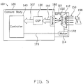
- a camera 100 is illustrated as having a camera body 120 and a lens 110 that can be either a zoom lens or a prime lens.
- the lens 110 includes a set of optical lenses 112 and a motor 114 configured to control positions of the set of optical lenses 112 in order to adjust an image distance, through a lens position, between the set of optical lenses 112 and a sensor 180.
- the optical lenses 112 receive light 150 that represents an object 190, which may include a main imaging object and a background.
- the light 150 is refracted through the set of optical lenses 112 to form an image on the sensor 180 via a light signal 152.
- the sensor 180 converts the light signal 152 from the lens 110 into an analogue dataflow 160, which is then converted into a digital dataflow 162 by a Digital Signal Processor (DSP) 130.
- the digital data in the dataflow 162 is passed to a controller 140, which performs focus measure value calculations and comparisons as set forth above.
- the focus measure calculations also include calculations of window evaluation values.
- the controller 140 sends a control signal 170 to the motor 114 for changing the position of the lense 112 in order to change the image distance between the set of optical lenses 112 and the sensor 180.
- the image is transmitted via the dataflow 160 to the DSP 130, which generates the dataflow 162 to the controller 140.
- the controller 140 calculates the focus measure values according to the new image data. This process forms a close-loop control system for focusing an image.
- the controller 140 calculates and compares the focus measure values for a number of lens positions and selects one motor 114 position, or a lens position, that corresponds to an optimal focus measure value.
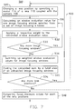
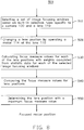
- Fig. 6 shows a method 500 for enabling the camera 100 to automatically perform image focusing operations.
- the controller 140 can select a set of image focusing windows at 510 for calculating focus measure values and determining a lens position when focusing.
- the embodiments disclosed herein can select image focusing windows based on statistic data.
- the controller 140 changes, at 520, the lens position by operating the motor 114 (shown in Fig. 5 ) of the lens 110 (shown in Fig.
- the controller 140 For each such lens position, the controller 140 memorizes its motor 114 position and calculates window evaluation values for each of the selected image focusing windows at 530. Also at 530, the controller 140 calculates focus measure values for each of the lens positions based on the calculated window evaluation values and respective weights for each of the image focusing windows. The calculated focus measure values are used for indicating whether an object is focused, where a greater focus measure value represents a clearer image. The weights for each of the image focusing windows are determined by statistic data specific to the camera 100 and the lens 110 coupled to the camera 100. The focus measure values are compared at 540 to determine an optimal lens position for the lens 110 and its corresponding motor 114 position.
- Fig. 7 shows an alternative embodiment of the method 500 with articulated functional block 530.
- the controller 140 calculates a window evaluation value for one image focusing window, at 531.
- the calculated window evaluation value, at 532, for the image focusing window can be applied with a respective weight that is specific to the image focusing window to provide a weighted window evaluation value for the image focusing window.
- the controller 140 checks whether window evaluation values are calculated for all selected image focusing windows. If not all image focusing windows are calculated, the controller 140 moves to next image focusing window and calculates the window evaluation value for that image focusing window as described earlier in this paragraph.
- the controller 140 sums the weighted window evaluation values for selected image focusing windows to provide a weighted sum of window evaluation values for the lens position.
- functional blocks 532 and 534 can be combined into a new functional block 534. In that case, the respective weights are applied when summing up the window evaluation values for select image focusing windows to provide a weighted sum of window evaluation values in a single step.
- the controller 140 further divides, at 535, the weighted sum of window evaluation values by a total area of the calculated image focusing windows to get an average weighted sum of window evaluation values.
- the controller 140 thereby can advantageously take the average weighted sum of window evaluation values as the focus measure value.
- the controller 140 can utilize the weighted sum of window evaluation values as the focus measure value.
- functional block 535 is optional and can be omitted from the method 500.
- the controller checks whether all selected lens positions have been calculated; if not, the controller 140 changes the lens position by operating the motor 114 (shown in Fig. 5 ) and calculates another focus measure value as described above. If all selected lens positions have been calculated, the controller compares the focus measure values to get an optimal lens position that corresponds to an optimal motor position.
- FIG. 8 An alternative embodiment of the method 500 of Fig. 6 or Fig. 7 is illustrated in Fig. 8 .
- the selection of image focusing windows, at 510 can be conducted based on one or more sets of built-in rules.
- the built-in rules can be derived from statistic data specific to the camera 100 (shown in Fig. 5 ) and/or specific to the lens 110 (shown in Fig. 5 ) coupled to the camera 100.
- the weights (shown in Fig. 7 ) applied can also be calculated from the statistic data specific to the camera 100 and/or the lens 110 coupled to the camera 100.
- the method 500 shown in Fig. 8 can include a functional block 550 to determine a lens position and its corresponding motor position by selecting a maximum focus measure value among the calculated focus measure values.
- a maximum focus measure value represents a lens position for a clearest image.
- a maximum focus measure value represents a maximum sum of window evaluation values, which means a best combined clearness for all of the image focusing windows. The weights applied when summing the window evaluations values can give special attention to a main imaging region on statistic bases.
- Fig. 9 illustrates another alternative embodiment of the method 500 of Fig. 6 , Fig. 7 or Fig. 8 .
- a set of five built-in regions including one in the center of an image frame and the other four arranged surrounding the center region, are selected as the set of image focusing windows.
- the four surrounding image focusing windows are centered at intersections of two horizontal trisecting lines and two vertical trisecting lines of the image frame. Statistically, a main imaging object is more likely found in one or more of those five regions.
- the controller 140 calculates focus measure values, at 530.
- the focus measure values can be calculated, at 530, in the manner set forth above with reference to Fig. 7 .
- the controller 140 can calculate a window evaluation value and applies a respective weight for each of the five image focusing windows at 531 and 532.
- the controller 140 can sum the weighted window evaluation values for the five image focusing windows at 534 to provide a weighted sum of window evaluation values.
- the weight sum of window evaluation values can be divided with a total area of the five image focusing windows to provide a focus measure value for the lens position.
- an image frame is divided into sixteen rows and sixteen columns (16 ⁇ 16) to form two hundred, fifty-six subareas each having a uniform area.
- the image focusing window located the center takes four of those two hundred, fifty-six subareas, and any of the other four image focusing windows takes one subarea.
- the center image focusing window is preferably selected having five hundred, twelve by two hundred, fifty-six (512 ⁇ 256) pixels. Any of the other four image focusing windows is selected having two hundred, fifty-six by one hundred, twenty-eight (256 ⁇ 128) pixels.
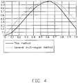
- the result focus curve by the approach of the preferred embodiments is much sharper than the focus curve obtained by the general multi-region selection approach.
- the approach conducts calculations only against selected image focusing windows, the amount of calculations can be controlled and limited, which makes the embodiments applicable for video applications.
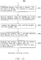
- a first step of the method 800 is to collect statistic data specifically to the camera 100 for each of the lenses 110 (shown in Fig. 5 ), at 810.
- the statistic data include probabilities for a main imaging region to fall into each region of an image frame and/or a ratio of the main imaging region to the total area of a specific region.
- one or more sets of rules for selecting image focusing windows are summarized and derived from the collected statistic data.
- weights associated with each of the image focusing windows within each set of image focusing windows are also calculated based on the same statistic data.
- the derived selection rules and the calculated weights are loaded into the camera 100 (show in Fig. 1 ).
- the camera 100 is enabled to use the loaded selection rules, via the controller 140, to select image focusing windows when performing a focusing operation.
- Functional block 840 includes adding necessary hardware and/or software to make the controller 140 (shown in Fig. 5 ) to have the capacity to utilize the loaded selection rules.
- the camera 100 is enabled to use the loaded weights, via the controller 140, to calculate focus measure values when performing a focusing operation.
- Functional block 850 includes adding necessary hardware and/or software to make the controller 140 (shown in Fig. 5 ) to have the capacity to utilize the loaded weights when performing a focusing operation.
- a last aspect of this disclosure is a camera 100 using any of the embodiments illustrated in Fig. 6 , Fig. 7 , Fig. 8 or Fig. 9 .
- the camera 100 is capable of coupling with a lens 110.
- a controller 140 of the camera 100 has access to one or more sets of image focusing window selection rules. The rules are summarize and/or derived from statistic data specific to the camera 100 and each lens 110 which is able to be coupled with the camera 100.
- the controller 140 can use the one or more sets of image focusing window selection rules in selecting a set of image focusing windows when focusing a picture.
- the controller 140 can also have access to one set or more sets of weights, calculated based on the statistic data, in calculating a focus measure value for each lens position.
- Each lens position corresponds to a motor position selected from a plurality of different motor positions.
- the controller 140 can select a motor position, which corresponds to a maximum focus measure value of all calculated focus measure values.
- the system and method have been described with reference to a camera for illustrative purpose only, the above described embodiments may apply to any conventional or nonconventional type of imaging device that is capable of automatic image focusing with a lens.
- the lens can be either an optical lens or an electronic lens.
- Typical imaging devices include cameras which can couple with lenses and video recorders with autofocusing capacities.
- the embodiments of this disclosure are not limited to those particular applications.
Landscapes
- Engineering & Computer Science (AREA)
- Multimedia (AREA)
- Signal Processing (AREA)
- Studio Devices (AREA)
- Automatic Focus Adjustment (AREA)
- Focusing (AREA)
Claims (3)
- Procédé de fabrication d'une caméra (100) pouvant être couplée à une lentille (112) et pouvant assurer la mise au point automatique d'une image dans une région d'image principale, comprenant :la collecte de données statistiques pour la caméra (100) et la lentille (112) ;l'obtention de règles de sélection de fenêtre de mise au point d'image à partir desdites données statistiques ;le chargement des règles de sélection de fenêtre de mise au point d'image et de pondérations respectives pour fenêtres de mise au point d'image définies par les règles de sélection de fenêtre de mise au point d'image dans la caméra (100), dans lequel lesdites règles de sélection de fenêtre de mise au point d'image sont des règles intégrées obtenues à partir des données statistiques spécifiques à la caméra (100) et à la lentille (112), dans lequel les données statistiques incluent des probabilités pour que la région d'imagerie principale se trouve dans chaque région d'une trame d'image, et dans lequel les pondérations respectives associées à chacune des fenêtres de mise au point d'image au sein de l'ensemble de fenêtres de mise au point sont calculées sur la base des données statistiques ;le fait de permettre à la caméra (100) d'utiliser lesdites règles de sélection de fenêtre de mise au point d'image en sélectionnant un ensemble de fenêtres de mise au point d'image pour la trame d'image à chaque position de lentille, dans lequel ladite sélection de l'ensemble de fenêtres de mise au point d'image est basée sur un ou plusieurs des ensembles de règles de sélection de fenêtre de mise au point d'image ; etle fait de permettre à la caméra (100) d'utiliser lesdites pondérations respectives pour calculer des valeurs de mesure de mise au point lors de la prise d'une photographie par la caméra (100).
- Procédé selon la revendication 1, dans lequel chacune des positions de lentille correspond à une position de moteur d'une pluralité de positions différentes d'un moteur associé à la lentille.
- Procédé selon la revendication 2, comprenant en outre :
le fait de permettre à la caméra (100) de sélectionner une position de moteur correspondant à une valeur de mesure de mise au point maximale en tant que position de lentille sélectionnée pour la photographie.
Applications Claiming Priority (1)
| Application Number | Priority Date | Filing Date | Title |
|---|---|---|---|
| PCT/CN2014/087546 WO2016045086A1 (fr) | 2014-09-26 | 2014-09-26 | Système et procédé de mise au point automatique sur la base de données statistiques |
Publications (3)
| Publication Number | Publication Date |
|---|---|
| EP3061237A1 EP3061237A1 (fr) | 2016-08-31 |
| EP3061237A4 EP3061237A4 (fr) | 2016-11-02 |
| EP3061237B1 true EP3061237B1 (fr) | 2021-11-10 |
Family
ID=55580133
Family Applications (1)
| Application Number | Title | Priority Date | Filing Date |
|---|---|---|---|
| EP14902569.4A Not-in-force EP3061237B1 (fr) | 2014-09-26 | 2014-09-26 | Système et procédé de mise au point automatique sur la base de données statistiques |
Country Status (5)
| Country | Link |
|---|---|
| US (2) | US9509898B2 (fr) |
| EP (1) | EP3061237B1 (fr) |
| JP (1) | JP6537083B2 (fr) |
| CN (2) | CN108710192B (fr) |
| WO (1) | WO2016045086A1 (fr) |
Families Citing this family (10)
| Publication number | Priority date | Publication date | Assignee | Title |
|---|---|---|---|---|
| JP6537083B2 (ja) * | 2014-09-26 | 2019-07-03 | エスゼット ディージェイアイ テクノロジー カンパニー リミテッドSz Dji Technology Co.,Ltd | 自動合焦のための方法および撮像装置 |
| CN107800951B (zh) * | 2016-09-07 | 2020-07-14 | 深圳富泰宏精密工业有限公司 | 电子装置及其镜头切换方法 |
| EP3542218B1 (fr) * | 2016-11-21 | 2021-03-17 | Nokia Technologies Oy | Procédé et appareil pour l'étalonnage d'une unité de caméra |
| CN108564541B (zh) * | 2018-03-28 | 2022-04-15 | 麒麟合盛网络技术股份有限公司 | 一种图像处理方法及装置 |
| CN108769538B (zh) * | 2018-08-16 | 2020-09-29 | Oppo广东移动通信有限公司 | 自动对焦方法、装置、存储介质及终端 |
| JP6690105B1 (ja) * | 2018-10-31 | 2020-04-28 | エスゼット ディージェイアイ テクノロジー カンパニー リミテッドSz Dji Technology Co.,Ltd | 制御装置、撮像装置、システム、制御方法、及びプログラム |
| TWI781490B (zh) * | 2020-02-27 | 2022-10-21 | 日商斯庫林集團股份有限公司 | 對焦位置檢測方法、對焦位置檢測裝置、記錄媒體及對焦位置檢測用程式 |
| JP2021135389A (ja) * | 2020-02-27 | 2021-09-13 | 株式会社Screenホールディングス | 合焦位置検出方法、合焦位置検出装置および合焦位置検出用プログラム |
| CN111797790B (zh) * | 2020-07-10 | 2021-11-05 | 北京字节跳动网络技术有限公司 | 图像处理方法和装置、存储介质和电子设备 |
| CN118470281B (zh) * | 2024-06-04 | 2025-02-28 | 华翌智能装备(杭州)有限公司 | 一种pcb板电子元器件自动检测用最优点位计算方法 |
Family Cites Families (24)
| Publication number | Priority date | Publication date | Assignee | Title |
|---|---|---|---|---|
| JP2560722B2 (ja) * | 1986-05-16 | 1996-12-04 | ミノルタ株式会社 | 多点測光カメラ |
| JP2749085B2 (ja) * | 1988-12-13 | 1998-05-13 | オリンパス光学工業株式会社 | 多点測距カメラ |
| JP2881790B2 (ja) * | 1988-12-29 | 1999-04-12 | 株式会社ニコン | 焦点検出装置 |
| JP2003107332A (ja) * | 2001-09-28 | 2003-04-09 | Nikon Corp | カメラ |
| JP2003107331A (ja) * | 2001-09-28 | 2003-04-09 | Nikon Corp | カメラ |
| US7158182B2 (en) | 2001-09-28 | 2007-01-02 | Nikon Corporation | Camera that engages in a focusing operation through a contrast method |
| JP4577113B2 (ja) * | 2005-06-22 | 2010-11-10 | オムロン株式会社 | 対象決定装置、撮像装置および監視装置 |
| TWI274222B (en) * | 2005-06-27 | 2007-02-21 | Asia Optical Co Inc | Automatic focusing method and electronic apparatus using the method |
| JP2007310004A (ja) * | 2006-05-16 | 2007-11-29 | Citizen Holdings Co Ltd | 自動合焦点装置 |
| TWI374664B (en) | 2007-12-05 | 2012-10-11 | Quanta Comp Inc | Focusing apparatus and method |
| US8238681B2 (en) * | 2008-11-25 | 2012-08-07 | Nokia Corporation | Adaptive configuration of windows-of-interest for accurate and robust focusing in multispot autofocus cameras |
| CN101625452B (zh) | 2009-06-19 | 2011-03-02 | 深圳市中瀛鑫科技股份有限公司 | 一种自动聚焦方法及装置、数码摄像装置 |
| JP5347845B2 (ja) | 2009-08-28 | 2013-11-20 | オムロン株式会社 | 画像処理プログラムおよび画像処理装置 |
| EP2448246B1 (fr) * | 2010-10-28 | 2019-10-09 | Axis AB | Procédé de mise au point |
| CN102087460A (zh) | 2010-12-28 | 2011-06-08 | 深圳市英迈吉科技有限公司 | Af对焦区域自由选择的自动对焦方法 |
| CN102253569B (zh) | 2011-01-17 | 2012-11-14 | 深圳市保千里电子有限公司 | 一种摄像机聚焦的方法及装置 |
| US9077890B2 (en) | 2011-02-24 | 2015-07-07 | Qualcomm Incorporated | Auto-focus tracking |
| JP5857610B2 (ja) * | 2011-10-13 | 2016-02-10 | 株式会社リコー | 撮像装置および撮像方法 |
| CN103424953B (zh) * | 2012-05-25 | 2017-08-11 | 中兴通讯股份有限公司 | 自动聚焦方法及装置 |
| GB2505151A (en) * | 2012-05-30 | 2014-02-26 | St Microelectronics Res & Dev | Auto focus method using focus statistics |
| KR20150061277A (ko) * | 2013-11-27 | 2015-06-04 | 삼성전자주식회사 | 영상 촬영 장치 및 이의 영상 촬영 방법 |
| CN104023175B (zh) * | 2014-04-25 | 2017-07-28 | 深圳英飞拓科技股份有限公司 | 一种自动聚焦方法和装置 |
| US9451155B2 (en) * | 2014-07-30 | 2016-09-20 | Apple Inc. | Depth-segmenting peak tracking autofocus |
| JP6537083B2 (ja) * | 2014-09-26 | 2019-07-03 | エスゼット ディージェイアイ テクノロジー カンパニー リミテッドSz Dji Technology Co.,Ltd | 自動合焦のための方法および撮像装置 |
-
2014
- 2014-09-26 JP JP2017510514A patent/JP6537083B2/ja not_active Expired - Fee Related
- 2014-09-26 EP EP14902569.4A patent/EP3061237B1/fr not_active Not-in-force
- 2014-09-26 WO PCT/CN2014/087546 patent/WO2016045086A1/fr not_active Ceased
- 2014-09-26 CN CN201810466497.4A patent/CN108710192B/zh not_active Expired - Fee Related
- 2014-09-26 CN CN201480076067.1A patent/CN106031155B/zh not_active Expired - Fee Related
-
2015
- 2015-12-17 US US14/972,889 patent/US9509898B2/en active Active
-
2016
- 2016-10-12 US US15/291,525 patent/US9813609B2/en active Active
Non-Patent Citations (1)
| Title |
|---|
| None * |
Also Published As
| Publication number | Publication date |
|---|---|
| EP3061237A4 (fr) | 2016-11-02 |
| US20160105601A1 (en) | 2016-04-14 |
| US20170034427A1 (en) | 2017-02-02 |
| WO2016045086A1 (fr) | 2016-03-31 |
| JP6537083B2 (ja) | 2019-07-03 |
| JP2017532590A (ja) | 2017-11-02 |
| CN108710192A (zh) | 2018-10-26 |
| CN108710192B (zh) | 2020-11-10 |
| US9813609B2 (en) | 2017-11-07 |
| EP3061237A1 (fr) | 2016-08-31 |
| US9509898B2 (en) | 2016-11-29 |
| CN106031155B (zh) | 2018-06-19 |
| CN106031155A (zh) | 2016-10-12 |
Similar Documents
| Publication | Publication Date | Title |
|---|---|---|
| EP3061237B1 (fr) | Système et procédé de mise au point automatique sur la base de données statistiques | |
| US9313419B2 (en) | Image processing apparatus and image pickup apparatus where image processing is applied using an acquired depth map | |
| US20210333690A1 (en) | Focus adjustment device, method for controlling the same, and image capture apparatus | |
| US8184196B2 (en) | System and method to generate depth data using edge detection | |
| US10904425B2 (en) | Image processing apparatus, control method therefor, and storage medium for evaluating a focusing state of image data | |
| CN102172013B (zh) | 抖动焦点的评估 | |
| US11682131B2 (en) | Image capturing apparatus and method of controlling image capturing apparatus | |
| CN102472882B (zh) | 进行自动调焦控制的摄像设备以及摄像设备的控制方法 | |
| CN101621625A (zh) | 摄像设备及其控制方法 | |
| US10187564B2 (en) | Focus adjustment apparatus, imaging apparatus, focus adjustment method, and recording medium storing a focus adjustment program thereon | |
| US20120057034A1 (en) | Imaging system and pixel signal readout method | |
| JP5845023B2 (ja) | 焦点検出装置及びそれを有するレンズ装置及び撮像装置 | |
| US20200228719A1 (en) | Focus control apparatus, imaging apparatus, focus control method, and storage medium | |
| CN103763458A (zh) | 一种场景变化检测方法及装置 | |
| JP5936358B2 (ja) | 画像表示装置、画像表示方法、撮像装置およびその制御方法、プログラムおよびそれを記憶する記憶媒体 | |
| JP7504688B2 (ja) | 画像処理装置、画像処理方法およびプログラム | |
| US20230072475A1 (en) | Accuracy estimation apparatus, image capturing apparatus, accuracy estimation method, control method, and storage medium | |
| JP6486098B2 (ja) | 撮像装置及びその制御方法 | |
| JP2001356384A (ja) | 測光装置 | |
| CN114979472B (zh) | 一种自动对焦方法、装置、设备及可读存储介质 | |
| US20170064191A1 (en) | Calculation device and image pickup device using calculation device and calculation method | |
| WO2021114194A1 (fr) | Procédé photographique, dispositif photographique et support d'enregistrement lisible par ordinateur | |
| US20190320122A1 (en) | Control apparatus, image capturing apparatus, control method, and non-transitory computer-readable storage medium | |
| CN106454066B (zh) | 图像处理设备及其控制方法 | |
| CN117082343A (zh) | 一种针对目标物体的自动聚焦方法、系统及装置 |
Legal Events
| Date | Code | Title | Description |
|---|---|---|---|
| PUAI | Public reference made under article 153(3) epc to a published international application that has entered the european phase |
Free format text: ORIGINAL CODE: 0009012 |
|
| 17P | Request for examination filed |
Effective date: 20160524 |
|
| AK | Designated contracting states |
Kind code of ref document: A1 Designated state(s): AL AT BE BG CH CY CZ DE DK EE ES FI FR GB GR HR HU IE IS IT LI LT LU LV MC MK MT NL NO PL PT RO RS SE SI SK SM TR |
|
| AX | Request for extension of the european patent |
Extension state: BA ME |
|
| A4 | Supplementary search report drawn up and despatched |
Effective date: 20160930 |
|
| RIC1 | Information provided on ipc code assigned before grant |
Ipc: H04N 5/232 20060101AFI20160926BHEP |
|
| DAX | Request for extension of the european patent (deleted) | ||
| STAA | Information on the status of an ep patent application or granted ep patent |
Free format text: STATUS: EXAMINATION IS IN PROGRESS |
|
| 17Q | First examination report despatched |
Effective date: 20180327 |
|
| GRAP | Despatch of communication of intention to grant a patent |
Free format text: ORIGINAL CODE: EPIDOSNIGR1 |
|
| STAA | Information on the status of an ep patent application or granted ep patent |
Free format text: STATUS: GRANT OF PATENT IS INTENDED |
|
| INTG | Intention to grant announced |
Effective date: 20210525 |
|
| GRAS | Grant fee paid |
Free format text: ORIGINAL CODE: EPIDOSNIGR3 |
|
| GRAA | (expected) grant |
Free format text: ORIGINAL CODE: 0009210 |
|
| STAA | Information on the status of an ep patent application or granted ep patent |
Free format text: STATUS: THE PATENT HAS BEEN GRANTED |
|
| AK | Designated contracting states |
Kind code of ref document: B1 Designated state(s): AL AT BE BG CH CY CZ DE DK EE ES FI FR GB GR HR HU IE IS IT LI LT LU LV MC MK MT NL NO PL PT RO RS SE SI SK SM TR |
|
| REG | Reference to a national code |
Ref country code: GB Ref legal event code: FG4D |
|
| REG | Reference to a national code |
Ref country code: AT Ref legal event code: REF Ref document number: 1447146 Country of ref document: AT Kind code of ref document: T Effective date: 20211115 Ref country code: CH Ref legal event code: EP |
|
| REG | Reference to a national code |
Ref country code: DE Ref legal event code: R096 Ref document number: 602014081236 Country of ref document: DE |
|
| REG | Reference to a national code |
Ref country code: IE Ref legal event code: FG4D |
|
| REG | Reference to a national code |
Ref country code: LT Ref legal event code: MG9D |
|
| REG | Reference to a national code |
Ref country code: NL Ref legal event code: MP Effective date: 20211110 |
|
| REG | Reference to a national code |
Ref country code: AT Ref legal event code: MK05 Ref document number: 1447146 Country of ref document: AT Kind code of ref document: T Effective date: 20211110 |
|
| PG25 | Lapsed in a contracting state [announced via postgrant information from national office to epo] |
Ref country code: RS Free format text: LAPSE BECAUSE OF FAILURE TO SUBMIT A TRANSLATION OF THE DESCRIPTION OR TO PAY THE FEE WITHIN THE PRESCRIBED TIME-LIMIT Effective date: 20211110 Ref country code: LT Free format text: LAPSE BECAUSE OF FAILURE TO SUBMIT A TRANSLATION OF THE DESCRIPTION OR TO PAY THE FEE WITHIN THE PRESCRIBED TIME-LIMIT Effective date: 20211110 Ref country code: FI Free format text: LAPSE BECAUSE OF FAILURE TO SUBMIT A TRANSLATION OF THE DESCRIPTION OR TO PAY THE FEE WITHIN THE PRESCRIBED TIME-LIMIT Effective date: 20211110 Ref country code: BG Free format text: LAPSE BECAUSE OF FAILURE TO SUBMIT A TRANSLATION OF THE DESCRIPTION OR TO PAY THE FEE WITHIN THE PRESCRIBED TIME-LIMIT Effective date: 20220210 Ref country code: AT Free format text: LAPSE BECAUSE OF FAILURE TO SUBMIT A TRANSLATION OF THE DESCRIPTION OR TO PAY THE FEE WITHIN THE PRESCRIBED TIME-LIMIT Effective date: 20211110 |
|
| PG25 | Lapsed in a contracting state [announced via postgrant information from national office to epo] |
Ref country code: IS Free format text: LAPSE BECAUSE OF FAILURE TO SUBMIT A TRANSLATION OF THE DESCRIPTION OR TO PAY THE FEE WITHIN THE PRESCRIBED TIME-LIMIT Effective date: 20220310 Ref country code: SE Free format text: LAPSE BECAUSE OF FAILURE TO SUBMIT A TRANSLATION OF THE DESCRIPTION OR TO PAY THE FEE WITHIN THE PRESCRIBED TIME-LIMIT Effective date: 20211110 Ref country code: PT Free format text: LAPSE BECAUSE OF FAILURE TO SUBMIT A TRANSLATION OF THE DESCRIPTION OR TO PAY THE FEE WITHIN THE PRESCRIBED TIME-LIMIT Effective date: 20220310 Ref country code: PL Free format text: LAPSE BECAUSE OF FAILURE TO SUBMIT A TRANSLATION OF THE DESCRIPTION OR TO PAY THE FEE WITHIN THE PRESCRIBED TIME-LIMIT Effective date: 20211110 Ref country code: NO Free format text: LAPSE BECAUSE OF FAILURE TO SUBMIT A TRANSLATION OF THE DESCRIPTION OR TO PAY THE FEE WITHIN THE PRESCRIBED TIME-LIMIT Effective date: 20220210 Ref country code: NL Free format text: LAPSE BECAUSE OF FAILURE TO SUBMIT A TRANSLATION OF THE DESCRIPTION OR TO PAY THE FEE WITHIN THE PRESCRIBED TIME-LIMIT Effective date: 20211110 Ref country code: LV Free format text: LAPSE BECAUSE OF FAILURE TO SUBMIT A TRANSLATION OF THE DESCRIPTION OR TO PAY THE FEE WITHIN THE PRESCRIBED TIME-LIMIT Effective date: 20211110 Ref country code: HR Free format text: LAPSE BECAUSE OF FAILURE TO SUBMIT A TRANSLATION OF THE DESCRIPTION OR TO PAY THE FEE WITHIN THE PRESCRIBED TIME-LIMIT Effective date: 20211110 Ref country code: GR Free format text: LAPSE BECAUSE OF FAILURE TO SUBMIT A TRANSLATION OF THE DESCRIPTION OR TO PAY THE FEE WITHIN THE PRESCRIBED TIME-LIMIT Effective date: 20220211 Ref country code: ES Free format text: LAPSE BECAUSE OF FAILURE TO SUBMIT A TRANSLATION OF THE DESCRIPTION OR TO PAY THE FEE WITHIN THE PRESCRIBED TIME-LIMIT Effective date: 20211110 |
|
| PG25 | Lapsed in a contracting state [announced via postgrant information from national office to epo] |
Ref country code: SM Free format text: LAPSE BECAUSE OF FAILURE TO SUBMIT A TRANSLATION OF THE DESCRIPTION OR TO PAY THE FEE WITHIN THE PRESCRIBED TIME-LIMIT Effective date: 20211110 Ref country code: SK Free format text: LAPSE BECAUSE OF FAILURE TO SUBMIT A TRANSLATION OF THE DESCRIPTION OR TO PAY THE FEE WITHIN THE PRESCRIBED TIME-LIMIT Effective date: 20211110 Ref country code: RO Free format text: LAPSE BECAUSE OF FAILURE TO SUBMIT A TRANSLATION OF THE DESCRIPTION OR TO PAY THE FEE WITHIN THE PRESCRIBED TIME-LIMIT Effective date: 20211110 Ref country code: EE Free format text: LAPSE BECAUSE OF FAILURE TO SUBMIT A TRANSLATION OF THE DESCRIPTION OR TO PAY THE FEE WITHIN THE PRESCRIBED TIME-LIMIT Effective date: 20211110 Ref country code: DK Free format text: LAPSE BECAUSE OF FAILURE TO SUBMIT A TRANSLATION OF THE DESCRIPTION OR TO PAY THE FEE WITHIN THE PRESCRIBED TIME-LIMIT Effective date: 20211110 Ref country code: CZ Free format text: LAPSE BECAUSE OF FAILURE TO SUBMIT A TRANSLATION OF THE DESCRIPTION OR TO PAY THE FEE WITHIN THE PRESCRIBED TIME-LIMIT Effective date: 20211110 |
|
| REG | Reference to a national code |
Ref country code: DE Ref legal event code: R097 Ref document number: 602014081236 Country of ref document: DE |
|
| PLBE | No opposition filed within time limit |
Free format text: ORIGINAL CODE: 0009261 |
|
| STAA | Information on the status of an ep patent application or granted ep patent |
Free format text: STATUS: NO OPPOSITION FILED WITHIN TIME LIMIT |
|
| 26N | No opposition filed |
Effective date: 20220811 |
|
| PG25 | Lapsed in a contracting state [announced via postgrant information from national office to epo] |
Ref country code: AL Free format text: LAPSE BECAUSE OF FAILURE TO SUBMIT A TRANSLATION OF THE DESCRIPTION OR TO PAY THE FEE WITHIN THE PRESCRIBED TIME-LIMIT Effective date: 20211110 |
|
| REG | Reference to a national code |
Ref country code: DE Ref legal event code: R079 Ref document number: 602014081236 Country of ref document: DE Free format text: PREVIOUS MAIN CLASS: H04N0005232000 Ipc: H04N0023600000 |
|
| PG25 | Lapsed in a contracting state [announced via postgrant information from national office to epo] |
Ref country code: SI Free format text: LAPSE BECAUSE OF FAILURE TO SUBMIT A TRANSLATION OF THE DESCRIPTION OR TO PAY THE FEE WITHIN THE PRESCRIBED TIME-LIMIT Effective date: 20211110 |
|
| REG | Reference to a national code |
Ref country code: DE Ref legal event code: R119 Ref document number: 602014081236 Country of ref document: DE |
|
| PG25 | Lapsed in a contracting state [announced via postgrant information from national office to epo] |
Ref country code: MC Free format text: LAPSE BECAUSE OF FAILURE TO SUBMIT A TRANSLATION OF THE DESCRIPTION OR TO PAY THE FEE WITHIN THE PRESCRIBED TIME-LIMIT Effective date: 20211110 |
|
| REG | Reference to a national code |
Ref country code: CH Ref legal event code: PL |
|
| GBPC | Gb: european patent ceased through non-payment of renewal fee |
Effective date: 20220926 |
|
| REG | Reference to a national code |
Ref country code: BE Ref legal event code: MM Effective date: 20220930 |
|
| PG25 | Lapsed in a contracting state [announced via postgrant information from national office to epo] |
Ref country code: IT Free format text: LAPSE BECAUSE OF FAILURE TO SUBMIT A TRANSLATION OF THE DESCRIPTION OR TO PAY THE FEE WITHIN THE PRESCRIBED TIME-LIMIT Effective date: 20211110 |
|
| PG25 | Lapsed in a contracting state [announced via postgrant information from national office to epo] |
Ref country code: LU Free format text: LAPSE BECAUSE OF NON-PAYMENT OF DUE FEES Effective date: 20220926 |
|
| PG25 | Lapsed in a contracting state [announced via postgrant information from national office to epo] |
Ref country code: LI Free format text: LAPSE BECAUSE OF NON-PAYMENT OF DUE FEES Effective date: 20220930 Ref country code: IE Free format text: LAPSE BECAUSE OF NON-PAYMENT OF DUE FEES Effective date: 20220926 Ref country code: FR Free format text: LAPSE BECAUSE OF NON-PAYMENT OF DUE FEES Effective date: 20220930 Ref country code: DE Free format text: LAPSE BECAUSE OF NON-PAYMENT OF DUE FEES Effective date: 20230401 Ref country code: CH Free format text: LAPSE BECAUSE OF NON-PAYMENT OF DUE FEES Effective date: 20220930 |
|
| PG25 | Lapsed in a contracting state [announced via postgrant information from national office to epo] |
Ref country code: BE Free format text: LAPSE BECAUSE OF NON-PAYMENT OF DUE FEES Effective date: 20220930 |
|
| PG25 | Lapsed in a contracting state [announced via postgrant information from national office to epo] |
Ref country code: GB Free format text: LAPSE BECAUSE OF NON-PAYMENT OF DUE FEES Effective date: 20220926 |
|
| PG25 | Lapsed in a contracting state [announced via postgrant information from national office to epo] |
Ref country code: HU Free format text: LAPSE BECAUSE OF FAILURE TO SUBMIT A TRANSLATION OF THE DESCRIPTION OR TO PAY THE FEE WITHIN THE PRESCRIBED TIME-LIMIT; INVALID AB INITIO Effective date: 20140926 |
|
| PG25 | Lapsed in a contracting state [announced via postgrant information from national office to epo] |
Ref country code: CY Free format text: LAPSE BECAUSE OF FAILURE TO SUBMIT A TRANSLATION OF THE DESCRIPTION OR TO PAY THE FEE WITHIN THE PRESCRIBED TIME-LIMIT Effective date: 20211110 |
|
| PG25 | Lapsed in a contracting state [announced via postgrant information from national office to epo] |
Ref country code: MK Free format text: LAPSE BECAUSE OF FAILURE TO SUBMIT A TRANSLATION OF THE DESCRIPTION OR TO PAY THE FEE WITHIN THE PRESCRIBED TIME-LIMIT Effective date: 20211110 |
|
| PG25 | Lapsed in a contracting state [announced via postgrant information from national office to epo] |
Ref country code: TR Free format text: LAPSE BECAUSE OF FAILURE TO SUBMIT A TRANSLATION OF THE DESCRIPTION OR TO PAY THE FEE WITHIN THE PRESCRIBED TIME-LIMIT Effective date: 20211110 |
|
| PG25 | Lapsed in a contracting state [announced via postgrant information from national office to epo] |
Ref country code: MT Free format text: LAPSE BECAUSE OF FAILURE TO SUBMIT A TRANSLATION OF THE DESCRIPTION OR TO PAY THE FEE WITHIN THE PRESCRIBED TIME-LIMIT Effective date: 20211110 |