EP3061090B1 - Concept for combined dynamic range compression and guided clipping prevention for audio devices - Google Patents
Concept for combined dynamic range compression and guided clipping prevention for audio devices Download PDFInfo
- Publication number
- EP3061090B1 EP3061090B1 EP14786881.4A EP14786881A EP3061090B1 EP 3061090 B1 EP3061090 B1 EP 3061090B1 EP 14786881 A EP14786881 A EP 14786881A EP 3061090 B1 EP3061090 B1 EP 3061090B1
- Authority
- EP
- European Patent Office
- Prior art keywords
- audio
- dynamic range
- stage
- range control
- metadata
- Prior art date
- Legal status (The legal status is an assumption and is not a legal conclusion. Google has not performed a legal analysis and makes no representation as to the accuracy of the status listed.)
- Active
Links
- 230000002265 prevention Effects 0.000 title claims description 185
- 230000006835 compression Effects 0.000 title description 19
- 238000007906 compression Methods 0.000 title description 19
- 239000008186 active pharmaceutical agent Substances 0.000 claims description 72
- 238000012545 processing Methods 0.000 claims description 50
- 238000000034 method Methods 0.000 claims description 36
- 238000010606 normalization Methods 0.000 claims description 23
- 230000005236 sound signal Effects 0.000 claims description 18
- 230000002123 temporal effect Effects 0.000 claims description 16
- 238000004590 computer program Methods 0.000 claims description 13
- 238000013507 mapping Methods 0.000 description 13
- 230000006978 adaptation Effects 0.000 description 11
- 238000006243 chemical reaction Methods 0.000 description 9
- 230000009467 reduction Effects 0.000 description 9
- 230000004048 modification Effects 0.000 description 8
- 238000012986 modification Methods 0.000 description 8
- 238000009877 rendering Methods 0.000 description 8
- 230000008859 change Effects 0.000 description 7
- 238000013459 approach Methods 0.000 description 4
- 238000000926 separation method Methods 0.000 description 4
- 238000009499 grossing Methods 0.000 description 3
- 230000005540 biological transmission Effects 0.000 description 2
- 230000001419 dependent effect Effects 0.000 description 2
- 230000000694 effects Effects 0.000 description 2
- 238000001914 filtration Methods 0.000 description 2
- 230000006870 function Effects 0.000 description 2
- 230000008569 process Effects 0.000 description 2
- 238000013139 quantization Methods 0.000 description 2
- 230000004044 response Effects 0.000 description 2
- 238000012546 transfer Methods 0.000 description 2
- PEIBAWRLFPGPAT-UHFFFAOYSA-N 1-(diazomethyl)pyrene Chemical compound C1=C2C(C=[N+]=[N-])=CC=C(C=C3)C2=C2C3=CC=CC2=C1 PEIBAWRLFPGPAT-UHFFFAOYSA-N 0.000 description 1
- 230000004075 alteration Effects 0.000 description 1
- 238000004891 communication Methods 0.000 description 1
- 239000000203 mixture Substances 0.000 description 1
Images


Classifications
-
- G—PHYSICS
- G10—MUSICAL INSTRUMENTS; ACOUSTICS
- G10L—SPEECH ANALYSIS OR SYNTHESIS; SPEECH RECOGNITION; SPEECH OR VOICE PROCESSING; SPEECH OR AUDIO CODING OR DECODING
- G10L19/00—Speech or audio signals analysis-synthesis techniques for redundancy reduction, e.g. in vocoders; Coding or decoding of speech or audio signals, using source filter models or psychoacoustic analysis
- G10L19/04—Speech or audio signals analysis-synthesis techniques for redundancy reduction, e.g. in vocoders; Coding or decoding of speech or audio signals, using source filter models or psychoacoustic analysis using predictive techniques
- G10L19/16—Vocoder architecture
- G10L19/167—Audio streaming, i.e. formatting and decoding of an encoded audio signal representation into a data stream for transmission or storage purposes
-
- G—PHYSICS
- G10—MUSICAL INSTRUMENTS; ACOUSTICS
- G10L—SPEECH ANALYSIS OR SYNTHESIS; SPEECH RECOGNITION; SPEECH OR VOICE PROCESSING; SPEECH OR AUDIO CODING OR DECODING
- G10L21/00—Processing of the speech or voice signal to produce another audible or non-audible signal, e.g. visual or tactile, in order to modify its quality or its intelligibility
- G10L21/02—Speech enhancement, e.g. noise reduction or echo cancellation
- G10L21/0316—Speech enhancement, e.g. noise reduction or echo cancellation by changing the amplitude
- G10L21/0324—Details of processing therefor
- G10L21/034—Automatic adjustment
-
- G—PHYSICS
- G06—COMPUTING; CALCULATING OR COUNTING
- G06F—ELECTRIC DIGITAL DATA PROCESSING
- G06F3/00—Input arrangements for transferring data to be processed into a form capable of being handled by the computer; Output arrangements for transferring data from processing unit to output unit, e.g. interface arrangements
- G06F3/16—Sound input; Sound output
- G06F3/165—Management of the audio stream, e.g. setting of volume, audio stream path
-
- G—PHYSICS
- G10—MUSICAL INSTRUMENTS; ACOUSTICS
- G10L—SPEECH ANALYSIS OR SYNTHESIS; SPEECH RECOGNITION; SPEECH OR VOICE PROCESSING; SPEECH OR AUDIO CODING OR DECODING
- G10L19/00—Speech or audio signals analysis-synthesis techniques for redundancy reduction, e.g. in vocoders; Coding or decoding of speech or audio signals, using source filter models or psychoacoustic analysis
- G10L19/018—Audio watermarking, i.e. embedding inaudible data in the audio signal
-
- H—ELECTRICITY
- H03—ELECTRONIC CIRCUITRY
- H03G—CONTROL OF AMPLIFICATION
- H03G11/00—Limiting amplitude; Limiting rate of change of amplitude ; Clipping in general
- H03G11/008—Limiting amplitude; Limiting rate of change of amplitude ; Clipping in general of digital or coded signals
-
- H—ELECTRICITY
- H03—ELECTRONIC CIRCUITRY
- H03G—CONTROL OF AMPLIFICATION
- H03G9/00—Combinations of two or more types of control, e.g. gain control and tone control
-
- H—ELECTRICITY
- H03—ELECTRONIC CIRCUITRY
- H03G—CONTROL OF AMPLIFICATION
- H03G9/00—Combinations of two or more types of control, e.g. gain control and tone control
- H03G9/005—Combinations of two or more types of control, e.g. gain control and tone control of digital or coded signals
-
- G—PHYSICS
- G10—MUSICAL INSTRUMENTS; ACOUSTICS
- G10L—SPEECH ANALYSIS OR SYNTHESIS; SPEECH RECOGNITION; SPEECH OR VOICE PROCESSING; SPEECH OR AUDIO CODING OR DECODING
- G10L19/00—Speech or audio signals analysis-synthesis techniques for redundancy reduction, e.g. in vocoders; Coding or decoding of speech or audio signals, using source filter models or psychoacoustic analysis
- G10L19/008—Multichannel audio signal coding or decoding using interchannel correlation to reduce redundancy, e.g. joint-stereo, intensity-coding or matrixing
Definitions
- the present invention relates to a concept for combined dynamic range compression and guided clipping prevention for audio devices.
- the present invention relates to an audio decoder, to a method for operating an audio decoder, and to a computer program for executing the method for operating an audio decoder.
- the inventive concept is based on the combination of several processing blocks, which together provide the required functionalities of a joint solution for dynamic range compression (DRC) and for guided clipping prevention (gCP).
- DRC dynamic range compression
- gCP guided clipping prevention
- the inventive concept is particularly suitable for audio systems wherein related configuration information as defined, e.g., in [M30100, M30101] is already available at the encoder and decoder.
- This information may be, for example, included in the header for file based transmission or in the unified speech and audio coding (USAC) configuration extension.
- the configuration information may include channel layouts, downmix instructions (e.g. downmix coefficients), dynamic range control instructions (e.g. applied dynamic range control characteristic, number of dynamic range control gain sequences for a track), and loudness information (e.g. program loudness, anchor loudness, true peak value). More details can be found in [M30100, M30101].
- the same applies to corresponding guided clipping prevention instructions which may be handled in the same manner as the information of the dynamic range control instructions box.
- the audio encoder is capable of producing a metadata bitstream which comprises dynamic range control gain sequences for a dynamic range control stage of an audio decoder as well as guided clipping prevention gain sequences for a guided clipping prevention stage of the audio decoder, wherein the dynamic range control gain sequences may be transmitted separately from the guided clipping prevention gain sequences.
- the metadata encoder uses, as input, dynamic range control gain sequences that are provided externally, e.g., by an external tool operated by a content provider.
- the possible temporal resolution of the dynamic range control gains may be in the range of a few samples.
- the dynamic range control gain values may usually be represented with sufficient resolution of up to 0.125 dB.
- the metadata encoder takes guided clipping prevention gain sequences as input.
- the compressed dynamic range control gain sequences and guided clipping prevention gain sequences may be transmitted to the receiver as side information included in the unified speech and audio coding extension payload.
- dynamic range control gain sequences should only include dynamic range control gains to perform dynamic range compression, whereas guided clipping prevention gains for clipping prevention are accommodated by the guided clipping prevention gains sequences.
- the temporal resolution of the guided clipping prevention gains may be the same as for the dynamic range control gains.
- Signal clipping at the decoder side can occur e.g. due to loudness normalization, downmixing, parametric coding tools, etc.
- a peak limiter detects audio samples in the input signal that exceed a defined maximum value, and applies a level reduction to the respective signal portions so that the samples of the output signal always stay below the defined maximum value.
- the level reduction has to be performed gradually, i.e. the gain factor applied to the signal may only change slowly over time, which is ensured by a gain smoothing filter.
- a look-ahead delay of the input signal before applying the gain factor is also used to allow for a smooth reduction of the gain starting already before a sudden signal peak.
- a decoder side peak limiter Since a decoder side peak limiter is usually not controlled from the encoder side (a content creator has no influence on the peak limiter processing), it produces an unguided clipping prevention gain sequence which is directly applied to the audio signal.
- a decoder side peak limiter always causes additional look-ahead delay (about 5ms or more) and computational complexity at the decoder side.
- guided clipping prevention gain sequences as used according to the invention allow to fully control the generation of clipping prevention gains at the encoder side (if desired, a content creator can have influence on the gain characteristics).
- the clipping prevention gain sequences are transmitted to the decoder side. If a suitable guided clipping prevention gain sequence for the current decoder configuration is available in the metadata bitstream, a decoder side peak limiter can be avoided in most cases. Thus, additional look-ahead delay and computational complexity at the decoder side can be avoided.
- Guided clipping prevention gain sequences can be transmitted for various decoder configurations like, e.g. for specific target loudness levels or for specific downmix configurations. If the decoder configuration matches, a suitable guided clipping prevention gain sequence can be applied to the decoder output signal. In many cases guided clipping prevention gain sequences can be optionally scaled to match a non-matching target loudness level (signal headroom is used as far as possible).
- the guided clipping prevention gain sequences are used to assure that no sample clipping occurs at the output of the audio decoder for a specific target level and downmix/format converter configuration.
- Each guided clipping prevention gain sequence may be optimized for a combination of a specific downmix/format converter configuration, a specific target level, and a specific dynamic range control gain sequence for channels together with specific dynamic range control gain sequences for the objects.
- the information about which guided clipping prevention gain sequence is associated with which dynamic range control gain sequence may be included in the guided clipping prevention instruction contained in the file header of the unified speech and audio coding configuration extension. It may also include the information related to the target level for which the guided clipping prevention gains have been determined at the encoder.
- the concept for dynamic range processing that is described above represents an approach to encoder side control of the entire processing chain.
- the separation of the metadata used for dynamic range control and guided clipping prevention allows for separate modification (scaling or mapping) of each of the gains, said modification depending on the decoder configuration and the playback scenario.
- the inventive concept gives the content provider full control of the final output of the audio decoder in order to meet given quality requirements.
- both dynamic range control gain sequences and guided clipping prevention gain sequences can be included for specific decoder configurations considered to be most important.
- a peak limiter may be discarded in many cases due to combined use of dynamic range control gain sequences and guided clipping prevention gain sequences.
- guided clipping prevention at the audio decoder side which is achieved by simply applying guided clipping prevention gains, is computationally more efficient than using a peak limiter.
- the information about which dynamic range control characteristics are associated with the different dynamic range control gain sequences may be included in the dynamic range control instruction contained in the file header in case of file based delivery or in the unified speech and audio coding configuration extensions.
- each dynamic range control sequence it is possible to define a set of different dynamic range control gains for different channels or groups of channels, each channel usually being associated with exactly one channel group. For example, in multi-channel movie sound it is often desired to apply a specific dynamic range control gain to the dialog channel.
- the remaining channels such as front left, front right, rear left, rear right, for example, may be processed by using a different dynamic range control gain.
- audio objects By analogy with the channel case, multiple dynamic range control sequences that are associated with audio objects or groups of objects can be supported. These object-related dynamic range control sequences can also be considered as being associated with a specific channel group within a channel-related set of dynamic range control gains.
- audio objects herein relates to single source sounds such as a door bell.
- the information about which dynamic range control characteristics are associated with the different dynamic range control gain sequences may be included in the dynamic range control instruction contained in the file header in case of file based delivery or in the unified speech and audio coding configuration extensions.
- the metadata encoder can be extended to also accept dynamic range control gain sequences having different dynamic range control gains for different frequency bands as input.
- the information about which dynamic range control characteristics are associated with the different dynamic range control gain sequences may be included in the dynamic range control instruction contained in the file header in case of file based delivery or in the unified speech and audio coding configuration extensions.
- each guided clipping prevention gain it is possible to define a set of different guided clipping prevention gains for different channels or groups of channels within each guided clipping prevention sequence, where each channel usually is associated with exactly one channel group. In typical operation modes the same guided clipping prevention gains are applied to all channels.
- the invention provides an audio decoder for decoding an audio bitstream and a metadata bitstream related to the audio bitstream according to claim 1.
- the invention provides flexibility at the audio decoder side while leaving the control of the entire processing chain at the encoder side.
- the separation of the metadata used for dynamic range control and guided clipping prevention allows for separate modification (scaling or mapping) of each of the gains, said modification depending on the audio decoder configuration and the playback scenario.
- the invention allows changing the underlying dynamic range control characteristic of a dynamic range control gain sequence from heavy compression to light compression if the dynamic range control gains are transmitted separately from the guided clipping prevention gains. This can be achieved by means of appropriate scaling or mapping of the values of the dynamic range control gain sequence.
- the decoder target level is lower than the target level used for computing the gains for guided clipping prevention at the encoder, a reduced attenuation of signal peaks can be allowed at the decoder by appropriately scaling the guided clipping prevention gains. Then, the level of strong signal peaks can be maintained or at least increased as compared to the case of applying the guided clipping prevention gains in an unmodified manner, which means that available headroom can be preserved.
- the metadata decoder is configured to extract from the metadata bitstream at least two dynamic range control gain sequences for the same audio frame comprising different dynamic range control gains.
- the information about which dynamic range control characteristics are associated with the different dynamic range control gain sequences may be included in the dynamic range control instruction contained in the file header in case of file based delivery or in the unified speech and audio coding configuration extensions.
- the metadata decoder is configured to extract from the metadata bitstream a dynamic range control gain sequence comprising at least two dynamic range control gains related to different audio channels and/or to different audio objects.
- each dynamic range control sequence it is possible to define a set of different dynamic range control gains for different channels or groups of channels, each channel usually being associated with exactly one channel group. For example, in multi-channel movie sound it is often desired to apply a specific dynamic range control gain to the dialog channel.
- the remaining channels such as front left, front right, rear left, rear right, for example, may be processed by using a different dynamic range control gain.
- audio objects By analogous with the channel case, multiple dynamic range control sequences that are associated with audio objects or groups of objects can be supported. These object-related dynamic range control sequences can also be considered as being associated with a specific channel group within a channel-related set of dynamic range control gains.
- audio objects herein relates to single source sounds such as a door bell.
- the metadata decoder is configured to extract from the metadata bitstream a dynamic range control gain sequence comprising at least two dynamic range control gains related to different frequency bands of the audio decoder.
- the metadata decoder can be extended to also accept dynamic range control gain sequences having different dynamic range control gains for different frequency bands as input.
- the time-domain audio signal has to be transformed into the appropriate frequency domain representation before applying multi-band dynamic range control gains.
- the information about which dynamic range control characteristics are associated with the different dynamic range control gain sequences may be included in the dynamic range control instruction contained in the file header in case of file based delivery or in the unified speech and audio coding configuration extensions.
- the metadata decoder is configured to extract from the metadata bitstream at least two guided clipping prevention gain sequences comprising different guided clipping prevention gains.
- the metadata decoder is configured to extract from the metadata bitstream a guided clipping prevention gain sequence comprising at least two guided clipping prevention gains related to different audio channels and/or to different audio objects.
- each guided clipping prevention gain it is possible to define a set of different guided clipping prevention gains for different channels or groups of channels within each guided clipping prevention sequence, where each channel usually is associated with exactly one channel group. In typical operation modes the same guided clipping prevention gains are applied to all channels.
- the audio decoder further comprises a metadata and parameter control stage configured to provide metadata and parameters to at least one of the adjustment stages on the basis of configuration information received from a configuration providing stage.
- the metadata and parameter control stage at the audio decoder may select the correct part of the metadata bitstream in accordance with the desired dynamic range control gain sequences.
- the scaling and mapping information can also be part of or derived from the decoder configuration information.
- the metadata and parameter control stage at the audio decoder selects the correct part of the bitstream in accordance with the desired guided clipping prevention gain sequences.
- the metadata and parameter control stage is configured to select, in the event that a plurality of dynamic range control gain sequences are received, which of the plurality of dynamic range control gain sequences is supplied to the dynamic range control stage.
- the selection of the dynamic range control sequence on the part of the metadata and parameter control stage can be based on the decoder configuration information such as channel layout, downmix instructions, object metadata, dynamic range control instructions, loudness information, and decoder target level.
- the metadata and parameter control stage is configured to select, in the event that a plurality of guided clipping prevention gain sequences is received, which of the plurality of guided clipping prevention gain sequences is supplied to the guided clipping prevention stage.
- the selection of the guided clipping prevention gain sequence on the part of the metadata and parameter control block is usually based on audio decoder configuration information described above.
- the dynamic range control stage in the direction of the signal flow is the first adjustment stage of the audio adjustment chain.
- Dynamic range control processing for channels may be performed before a potential downmixing or format conversion of the decoded audio channels in order to enable different gaining for the channel groups. Accordingly, the dynamic range control gains are applied to the objects before rendering. In the event that both - channels and objects - are present, the location of the dynamic range control processing remains the same: the channel related dynamic range control should be performed directly before the format converter stage, whereas the object related dynamic range control is performed before the object renderer.
- the audio adjustment chain comprises a format converter stage configured to adjust a channel configuration of the audio output signal.
- the format converter stage also referred to as downmixer (DMX)
- DMX downmixer
- the format converter stage may convert a 5.1 surround signal into a stereo signal.
- the audio adjustment chain comprises a loudness normalization stage configured to normalize the loudness of the audio output signal.
- the loudness normalization stage scales its audio input signal such that the output signal has the correct target loudness level.
- the scaling factor is derived from the difference between the program reference level (PRL) and the decoder target level (DTL) and provided by the decoder's metadata and parameter control to the loudness normalization block.
- the program reference level is obtained from the loudness information which is included, e.g., in the file header, whereas the decoder target level is a decoder configuration parameter. It is possible that multiple program reference level values are provided within the loudness information, where each corresponds to a specific configuration of an applied dynamic range control sequence and/or an applied downmix. In this case, the metadata and parameter control stage chooses the correct program reference level value while considering the given audio decoder configuration.
- the location of the loudness-processing step depends on the actual output configuration of the audio decoder. In general, the loudness normalization should be performed on the output channels of the audio decoder, e.g. after the mixer, or after format conversion, if
- the audio adjustment chain comprises a peak limiter stage configured to limit peaks of the audio output signal in the event that a threshold is exceeded.
- the peak limiter stage in the direction of the signal flow is the last adjustment stage of the audio adjustment chain.
- the peak limiter stage is therefore placed at the very end of the processing chain of the audio decoder to prevent any undesired clipping of the audio samples, e.g. just before the time domain output signal is converted from the floating point to the fixed point pulse code modulation format (PCM format).
- PCM format fixed point pulse code modulation format
- the peak limiter stage receives different signals as input, depending on the actual playback configuration.
- the two output channels for the headphones may be processed by the peak limiter stage. If the output channels of the mixer are played back directly, the peak limiter stage may process the corresponding loudspeaker channels. The same applies if the mixer output channels are converted to a different loudspeaker configuration (e.g. downmixed) by the format converter first.
- the peak limiter stage may detect audio samples in the time-domain signal that exceed the limiting threshold, and applies a level reduction to the respective signal portions so that the samples of the audio output signal always stay below the limiting threshold.
- the level reduction should be performed gradually, i.e. the gain factor applied to the signal may only change slowly over time, which is ensured by a gain smoothing filter.
- a look-ahead delay of the input signal of the peak limiter stage before applying the limiter gain factor is also used in order to allow for a smooth reduction of the gain starting already before sharp signal peaks. The delay can be adjusted to a given requirement, a practical choice being 5 ms.
- a common gain factor may be applied to all audio channels to reduce computational complexity.
- the information about the maximum peak of the audio signal can be exploited to discard the peak limiter stage if the decoder configuration implies that no clipping can occur in the audio processing chain.
- the peak limiter stage may also be discarded, e.g., if the audio decoder outputs audio samples with floating point precision and a clipping prevention is performed at a later point in the audio chain of the playback device.
- the peak limiter stage may also be disabled if no additional codec clipping occurs.
- the peak limiter may be considered as being an essential component in practice. There are numerous sources of clipping within the audio processing chain of the decoder. Special configurations may be covered by providing guided clipping prevention gain sequences. However, for flexible operation of the decoder, the peak limiter may be provided to assure that no clipping occurs.
- the audio adjustment chain comprises an object renderer stage configured to mix audio objects into channels of the audio output signal.
- the audio adjustment chain comprises a transducer adaption stage configured to adjust characteristics of the audio output signal to a transducer system used for reproducing the audio output signal.
- a frequency dependent transducer adaptation processing e.g. implemented by an equalization filter, can be included in the processing chain.
- the transducer adaptation stage receives an audio input signal and information about the characteristics of the transducer used for reproduction (loudspeaker or headphones).
- the task of the transducer adaption stage is to adapt the audio output signal to the transducer characteristics, especially when transducers have a limited frequency range and thereby will limit the frequency range of the audio output signal.
- the input signal of the peak limiter stage is reduced in level.
- signal peaks that exceed the limiting thresholds are reduced in level. Consequently, the effect of the peak limiting stage is less severe. This is advantageous because
- the transducer adaptation stage can also include signal-adaptive processing such that the band-limiting of the transducer is compensated for. Especially very small transducers are not capable of reproducing low-frequency signals.
- the invention provides a method for operating an audio decoder, in particular an audio decoder according to claim 13, for decoding an audio bitstream and a metadata bitstream related to the audio bitstream.
- the invention provides a computer program for performing, when running on a computer or a processor, the before-mentioned method.
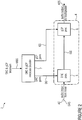
- Fig. 1 illustrates an example of an audio encoder 1 in a schematic view.
- Fig. 1 illustrates encoding of the dynamic range control gain sequences and guided clipping prevention gain sequences.
- the audio encoder 1 is configured to produce an audio bitstream comprising one or more audio channels AC and/or one or more audio objects AO, the audio encoder 1 comprising a metadata encoder 2 for producing a metadata bitstream MBS configured:
- the concept is based on the combination of several processing blocks, which together provide the required functionalities of a joint solution for dynamic range compression (DRC) and guided clipping prevention (gCP).
- DRC dynamic range compression
- gCP guided clipping prevention
- the concept is particularly suitable for audio systems wherein related configuration information as defined, e.g., in [M30100, M30101] is already available at the audio encoder 1 and at the audio decoder 3.
- This information may be included, for example, in the header for file based transmission or in the unified speech and audio coding (USAC) configuration extension.
- the configuration information may include channel layouts, downmix instructions (e.g. downmix coefficients), dynamic range control instructions (e.g. applied dynamic range control characteristic, number of dynamic range control gain sequences for a track), and loudness information (e.g. program loudness, anchor loudness, true peak value). More details can be found in [M30100, M30101].
- the same applies to corresponding guided clipping prevention instructions which may be handled in the same manner as the information of the dynamic range control instructions box.
- the audio encoder 1 is capable of producing a metadata bitstream MBS which comprises dynamic range control gain sequences DS for a dynamic range control stage 5 of an audio decoder 3 as well as guided clipping prevention gain sequences GS for a guided clipping prevention stage 6 of the audio decoder 3, wherein the dynamic range control gain sequences DS may be transmitted separately from the guided clipping prevention gain sequences GS.
- the metadata encoder uses, as input, dynamic range control gain sequences DS that are provided externally, e.g., by an external tool operated by a content provider.
- the possible temporal resolution of the dynamic range control gains may be in the range of a few samples.
- the dynamic range control gain values may usually be represented with sufficient resolution of up to 0.125 dB.
- the metadata encoder takes guided clipping prevention gain sequences GS as input.
- the compressed dynamic range control gain sequences DS and guided clipping prevention gain sequences GS may be transmitted to the receiver as side information included in the unified speech and audio coding extension payload.
- dynamic range control gain sequences DS should only include dynamic range control gains to perform dynamic range compression, whereas guided clipping prevention gains for clipping prevention are accommodated by the guided clipping prevention gains sequences GS.
- the temporal resolution of the guided clipping prevention gains may be the same as for the dynamic range control gains.
- the guided clipping prevention gain sequences GS are used to assure that no sample clipping occurs at the audio output signal AOS (see Fig. 2 ) of the audio decoder 3 for a specific target level and downmix/format converter configuration.
- Each guided clipping prevention gain sequence GS may be optimized for a combination of a specific downmix/format converter configuration, a specific target level, and a specific dynamic range control gain sequence for channels together with specific dynamic range control gain sequences for the objects.
- the information about which guided clipping prevention gain sequence GS is associated with which dynamic range control gain sequence DS may be included in the guided clipping prevention instruction contained in the file header of the unified speech and audio coding configuration extension. It may also include the information related to the target level for which the guided clipping prevention gains have been determined at the audio encoder 1.
- the concept for dynamic range processing described above represents an approach to audio encoder side control of the entire audio processing chain 4 (see Fig. 2 ).
- the separation of the metadata used for dynamic range control and guided clipping prevention allows for separate modification (scaling or mapping) of each of the gains, said modification depending on the audio decoder configuration and the playback scenario.
- both dynamic range control gain sequences DS and guided clipping prevention gain sequences GS can be included for specific audio decoder configurations considered to be most important.
- a peak limiter stage 12 may be discarded in many cases due to combined use of dynamic range control gain sequences DS and guided clipping prevention gain sequences GS. It has to be noted that guided clipping prevention at the audio decoder side, which is achieved by simply applying guided clipping prevention gains, is computationally more efficient than using a peak limiter 12.
- the metadata encoder 2 is configured to receive at least two dynamic range control gain sequences DS for the same audio frame comprising different dynamic range control gains, and to include the at least two dynamic range control gain sequences DS comprising the different dynamic range control gains into the metadata bitstream MBS.
- the information about which dynamic range control characteristics are associated with the different dynamic range control gain sequences DS may be included in the dynamic range control instruction contained in the file header in case of file based delivery or in the unified speech and audio coding configuration extensions.
- the metadata encoder is configured to receive a dynamic range control gain sequence DS comprising at least two dynamic range control gains related to different audio channels AC and/or to different audio objects AO, the metadata encoder 2 being configured to include the at least two dynamic range control gains DS related to different audio channels AC and/or to different audio objects AO and, optionally, the relationships of the dynamic range control gains to the audio channels AC and/or the audio objects AO into the metadata bitstream MBS.
- each dynamic range control sequence DS it is possible to define a set of different dynamic range control gains for different audio channels AC or groups of audio channels AC, wherein each audio channel AC usually is associated with exactly one channel group. For example, in multi-channel movie sound it is often desired to apply a specific dynamic range control gain to the dialog channel.
- the remaining channels such as front left, front right, rear left, rear right, for example, may be processed by using a different dynamic range control gain.
- multiple dynamic range control sequences DS that are associated with audio objects AO or groups of objects AO can be supported. These object-related dynamic range control sequences DS can also be considered as being associated with a specific channel group within a channel-related set of dynamic range control gains.
- audio objects herein relates to single source sounds such as a door bell.
- the information about which dynamic range control characteristics are associated with the different dynamic range control gain sequences DS may be included in the dynamic range control instruction contained in the file header in case of file based delivery or in the unified speech and audio coding configuration extensions.
- the metadata encoder 2 is configured to receive a dynamic range control gain sequence DS comprising at least two dynamic range control gains related to different frequency bands of the audio decoder, the metadata encoder 2 being configured to include the at least two dynamic range control gains DS related to different frequency bands of the audio decoder 3 and, optionally, the relationships of the dynamic range control gains to the frequency bands of the audio decoder 3 into the metadata bitstream MBS.
- the metadata encoder 2 can be extended to also accept, as input, dynamic range control gain sequences DS having different dynamic range control gains for different frequency bands.
- the information about which dynamic range control characteristics are associated with the different dynamic range control gain sequences DS may be included in the dynamic range control instruction contained in the file header in case of file based delivery or in the unified speech and audio coding configuration extensions.
- the metadata encoder is configured to receive at least two guided clipping prevention gain sequences GS comprising different guided clipping prevention gains and to include the at least two guided clipping prevention gain sequences GS comprising the different guided clipping prevention gains into the metadata bitstream MBS.
- each dynamic range control sequence DS is related to one of the guided clipping prevention gain sequences GS, the metadata encoder 2 being configured to include relationships between the dynamic range control sequences DS and the guided clipping prevention gain sequences GS into the metadata bitstream MBS.
- the metadata encoder is configured to receive a guided clipping prevention gain sequence GS comprising at least two guided clipping prevention gains related to different audio channels AC and/or to different audio objects AO, the metadata encoder 2 being configured to include the guided clipping prevention sequence GS comprising the at least two guided clipping prevention gains related to different audio channels AC and/or to different audio objects AO and, optionally, the relationships of the guided clipping prevention gains to the audio channels AC and/or the audio objects AO into the metadata bitstream MBS.
- a guided clipping prevention gain sequence GS comprising at least two guided clipping prevention gains related to different audio channels AC and/or to different audio objects AO
- the metadata encoder 2 being configured to include the guided clipping prevention sequence GS comprising the at least two guided clipping prevention gains related to different audio channels AC and/or to different audio objects AO and, optionally, the relationships of the guided clipping prevention gains to the audio channels AC and/or the audio objects AO into the metadata bitstream MBS.
- each guided clipping prevention gain is defined a set of different guided clipping prevention gains for different audio channels AC or groups of audio channels AC within each guided clipping prevention sequence GS, where each audio channel AC usually is associated with exactly one audio channel group. In typical operation modes the same guided clipping prevention gains are applied to all audio channels AC.
- the example provides a method for operating an audio encoder 1 for producing an audio bitstream comprising one or more audio channels and/or one or more audio objects, the audio encoder comprising a metadata encoder 2 for producing a metadata bitstream MBS, the method comprising the steps of:
- an example provides a computer program for performing, when running on a computer or a processor, the before-mentioned method.
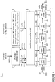
- Fig. 2 illustrates an example of an audio decoder 3 according to the invention in a schematic view.
- the audio decoder 3 for decoding an audio bitstream and a metadata bitstream MBS related to the audio bitstream, which are produced in particular by an audio encoder 1 according to the examples, the audio decoder 3 comprising:
- the metadata decoder 7 receives the metadata bitstream MBS containing the compressed dynamic range control gain sequences DS and guided clipping prevention gain sequences GS, for example from a unified speech and audio coding decoder.
- the metadata decoder 7 generates the uncompressed dynamic range control gain sequence DS from the compressed metadata bitstream MBS. Additionally, scaling or mapping of the resulting dynamic range control gains may be applied.
- the metadata decoder 7 additionally generates the uncompressed guiding clipping prevention gain sequences GS from the bitstream MBS containing compressed guided clipping prevention metadata.
- a scaling or mapping of the guided clipping prevention gains can be applied. This is especially useful if the audio decoder target level is lower than the target level that has been used for determining the guided clipping prevention gains sequence GS at the audio encoder 1. Then, mapping of the guided clipping prevention gains is possible, which optimally restores signal headroom while still assuring that no clipping occurs at the audio decoder output signal AOS.
- the dynamic range control stage 5 receives the uncompressed and optionally scaled or mapped dynamic range control gain sequences DS for each audio frame directly or indirectly from the metadata decoder 7.
- the metadata decoder 7 also may ensure that the final time-domain dynamic range control gain values are interpolated with a temporal resolution corresponding to the temporal resolution of the audio samples. These final dynamic range control gains may then be applied to the decoded audio signal DAS, where assignment of a certain dynamic range control sequence to the channels and/or objects is observed.
- the guided clipping prevention stage 6 receives the uncompressed and optionally scaled or mapped guided clipping prevention gain sequences GS for each audio frame directly or indirectly from the metadata decoder 7.
- the metadata decoder 7 may also ensure that the final time-domain guided clipping prevention gain values are interpolated with a temporal resolution corresponding to the temporal resolution of the audio samples. These final guiding clipping prevention gains may then be applied to the decoded audio signals or to signals ISG (or IGS in Fig. 3 , Fig. 4 and Fig. 5 ) derived from the decoded audio signals DAS, where assignment of a certain guided clipping prevention sequence to the channels and/or objects is observed.
- the example provides flexibility at the audio decoder side while leaving the control of the entire processing chain at the encoder side.
- the separation of the metadata used for dynamic range control and guided clipping prevention allows for separate modification (scaling or mapping) of each of the gains, said modification depending on the audio decoder configuration and the playback scenario.
- the example allows changing the underlying dynamic range control characteristic of a dynamic range control gain sequence DS from heavy compression to light compression if the dynamic range control gains are transmitted separately from the guided clipping prevention gains. This can be achieved by means of appropriate scaling or mapping of the values of the dynamic range control gain sequence DS.
- the decoder target level is lower than the target level used for computing the gains for guided clipping prevention at the audio encoder 1
- reduced attenuation of signal peaks can be allowed at the audio decoder 3 by appropriately scaling the guided clipping prevention gains.
- the level of strong signal peaks can be maintained or at least be increased as compared to the case of applying the guided clipping prevention gains in an unmodified manner, which means that available headroom can be preserved.
- the metadata decoder 7 is configured to extract from the metadata bitstream MBS at least two dynamic range control gain sequences DS for the same audio frame comprising different dynamic range control gains.
- the information about which dynamic range control characteristics are associated with the different dynamic range control gain sequences DS may be included in the dynamic range control instruction contained in the file header in case of file based delivery or in the unified speech and audio coding configuration extensions.
- the metadata decoder 7 is configured to extract from the metadata bitstream MBS a dynamic range control gain sequence DS comprising at least two dynamic range control gains related to different frequency bands of the audio decoder 3.
- the metadata decoder 7 can be extended to also accept, as input, dynamic range control gain sequences DS having different dynamic range control gains for different frequency bands.
- the time-domain audio signal has to be transformed into the appropriate frequency domain representation before applying multi-band dynamic range control gains.
- the information about which dynamic range control characteristics are associated with the different dynamic range control gain sequences DS may be included in the dynamic range control instruction contained in the file header in case of file based delivery or in the unified speech and audio coding configuration extensions.
- the metadata decoder 7 is configured to extract from the metadata bitstream MBS at least two guided clipping prevention gain sequences GS comprising different guided clipping prevention gains.
- the example provides a method for operating an audio decoder 3, in particular an audio decoder 3 according to the examples, for decoding an audio bitstream and a metadata bitstream MBS related to the audio bitstream, which are produced in particular by an audio encoder according to the examples, the method comprises the steps of:
- the example provides a computer program for performing, when running on a computer or a processor, the before-mentioned method.
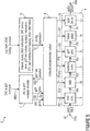
- Fig. 3 illustrates a first embodiment of an audio decoder 3 according to the invention in a schematic view.
- the metadata decoder 7 is configured to extract from the metadata bitstream MBS a dynamic range control gain sequence DS comprising at least two dynamic range control gains related to different audio channels.
- each dynamic range control sequence DS it is possible to define a set of different dynamic range control gains for different channels or groups of channels, each channel usually being associated with exactly one channel group. For example, in multi-channel movie sound it is often desired to apply a specific dynamic range control gain to the dialog channel.
- the remaining channels such as front left, front right, rear left, rear right, for example, may be processed by using a different dynamic range control gain.
- the metadata decoder 7 is configured to extract from the metadata bitstream MBS a guided clipping prevention gain sequence GS comprising at least two guided clipping prevention gains related to different audio channels.
- each guided clipping prevention gain it is possible to define a set of different guided clipping prevention gains for different channels or groups of channels within each guided clipping prevention sequence, where each channel usually is associated with exactly one channel group. In typical operation modes the same guided clipping prevention gains are applied to all channels.
- the audio decoder 3 further comprises a metadata and parameter control stage 8 configured to provide metadata and parameters DS, GS, CLA, DI, DTL, PRL, IS, OMD, ICT to at least one of the adjustment stages 5, 6, 10, 11, 12, 13, 14 on the basis of configuration information received from a configuration providing stage 9 (see also Fig. 4 and 5 ).
- a metadata and parameter control stage 8 configured to provide metadata and parameters DS, GS, CLA, DI, DTL, PRL, IS, OMD, ICT to at least one of the adjustment stages 5, 6, 10, 11, 12, 13, 14 on the basis of configuration information received from a configuration providing stage 9 (see also Fig. 4 and 5 ).
- the metadata and parameter control stage 8 at the audio decoder may select the correct part of the metadata bitstream MBS in accordance with the desired dynamic range control gain sequences DS by sending a gain sequence selection signal GSS to the metadata decoder 7.
- the scaling and mapping information can also be part of or derived from the decoder configuration information CI.
- the metadata and parameter control stage 8 at the audio decoder 3 selects the correct part of the bitstream MBS in accordance with the desired guided clipping prevention gain sequences GS.
- the metadata and parameter control stage 8 is configured to select, in the event that a plurality of dynamic range control gain sequences DS is received, which of the plurality of dynamic range control gain sequences DS is supplied to the dynamic range control stage 5.
- the selection of the dynamic range control sequences DS on the part of the metadata and parameter control stage 8 can be based on the decoder configuration information CI such as channel layout CLA, downmix instructions DI, object metadata OMD (see Fig. 4 ), dynamic range control instructions, loudness information PRL, and decoder target level DTL, and may be executed by sending a gain sequence selection signal GSS to the metadata decoder 7.
- the metadata and parameter control stage 8 is configured to select, in the event that a plurality of guided clipping prevention gain sequences GS is received, which of the plurality of guided clipping prevention gain sequences GS is supplied to the guided clipping prevention stage 6.
- the selection of the guided clipping prevention gain sequence GS on the part of the metadata and parameter control block 8 is usually based on audio decoder configuration information CI described above.
- the dynamic range control stage 5 in the direction of the signal flow is the first adjustment stage of the audio adjustment chain 4.
- Dynamic range control processing for channels may be performed before a potential downmixing or format conversion of the decoded audio channels AC in order to enable different gaining for the channel groups. Accordingly, the dynamic range control gains are applied to the objects AO before rendering (see Fig.4 ). In the event that both - channels AC and objects AO - are present, the location of the dynamic range control processing remains the same: the channel related dynamic range control should be performed directly before the format converter stage 10 (see Fig. 4 ), whereas the object related dynamic range control is performed before the object renderer 13 (see Fig.4 ).
- the audio adjustment chain 4 comprises a format converter stage 10 configured to adjust a channel configuration of the audio output signal AOS.
- the format converter stage 10 also referred to as downmixer (DMX)
- DMX downmixer
- the format converter stage may convert a 5.1 surround signal into a stereo signal.
- the audio adjustment chain 4 comprises a loudness normalization stage 11 configured to normalize the loudness of the audio output signal AOS.
- the loudness normalization stage 11 may scale its audio input signal OCF such that the output signal IGS has the correct target loudness level.
- the scaling factor is derived from the difference between the program reference level PRL and the decoder target level DTL and provided by the decoder's metadata and parameter control stage 8 to the loudness normalization stage 11.
- the program reference level PRL may be obtained from the loudness information included, e.g., in the file header, whereas the decoder target level is a decoder configuration parameter. It is possible that multiple program reference level PRL values are provided within the loudness information, where each corresponds to a specific configuration of an applied dynamic range control sequence DS and/or an applied downmix.
- the metadata and parameter control stage 8 chooses the correct program reference level value PRL while considering the given audio decoder configuration.
- the location of the loudness-processing step depends on the actual output configuration of the audio decoder 3. In general, the loudness normalization should be performed on the output channels of the audio decoder 3, e.g. after the mixer, or after format conversion stage 10, if applicable.
- the audio adjustment chain 4 comprises a peak limiter stage 12 configured to limit peaks of the audio output signal AOS in the event that a threshold is exceeded.
- the peak limiter stage 12 in the direction of the signal flow is the last adjustment stage of the audio adjustment chain 4.
- the peak limiter stage 12 is therefore placed at the very end of the processing chain 4 of the audio decoder 3 to prevent any undesired clipping of the audio samples, e.g. just before the time domain output signal is converted from the floating point to the fixed point pulse code modulation format (PCM format).
- PCM format fixed point pulse code modulation format
- any dynamic range control stage 5 and loudness normalization stage 11 described in the previous section is located before the peak limiter stage 12.
- the peak limiter stage receives different signals IPL as input, depending on the actual playback configuration. In case of binaural rendering, the two output channels for the headphones may be processed by the peak limiter stage 12.
- the peak limiter stage 12 may process the corresponding loudspeaker channels. The same applies if the mixer output channels are converted to a different loudspeaker configuration (e.g. downmixed) by the format converter 10 first.
- the peak limiter stage 12 may detect audio samples in the time-domain signal that exceed the limiting threshold, and applies a level reduction to the respective signal portions so that the samples of the audio output signal AOS always stay below the limiting threshold.
- the level reduction should be performed gradually, i.e. the gain factor applied to the signal may only change slowly over time, which is ensured by a gain smoothing filter.
- a look-ahead delay of the input signal of the peak limiter stage before applying the limiter gain factor is also used in order to allow for a smooth reduction of the gain starting already before sharp signal peaks. The delay can be adjusted to a given requirement, a practical choice being 5 ms. In case of multi-channel audio a common gain factor may be applied to all audio channels to reduce computational complexity.
- the information about the maximum peak IS of the audio signal DAS can be exploited to discard the peak limiter stage 12 if the decoder configuration implies that no clipping can occur in the audio processing chain.
- the peak limiter stage 12 may also be discarded, e.g., if the audio decoder 3 outputs audio samples with floating point precision, and clipping prevention is performed at a later point in the audio chain of the playback device.
- the peak limiter stage may also be disabled if no additional codec clipping occurs.
- the peak limiter 12 may be considered as being an essential component in practice. There are numerous sources of clipping within the audio processing chain of the audio decoder 3. Special configurations may be covered by providing guided clipping prevention gain sequences. However, for flexible operation of the decoder, the peak limiter may be provided to assure that no clipping occurs. As shown in Fig. 3 , the guided clipping prevention processing may be performed after format conversion and loudness normalization of the audio channels. If no format conversion is applied, the guided clipping prevention gains may be directly applied to the output ISG of the dynamic range control stage 5.
- Fig. 4 illustrates a second embodiment of an audio decoder according to the invention in a schematic view.
- Fig. 4 depicts a configuration of dynamic range control processing for audio objects AO.
- the dynamic range control processing is performed on the audio object signals before rendering. Loudness normalization and clipping prevention is performed after the object rendering to channels.
- the audio adjustment chain 4 comprises an object renderer stage 13 configured to mix audio objects AO into channels of the audio output signal AOS.
- the metadata decoder 7 is configured to extract from the metadata bitstream MBS a dynamic range control gain sequence DS comprising at least two dynamic range control gains related to different audio objects AO.
- audio objects AO herein relates to single source sounds such as a door bell.
- the metadata decoder 7 is configured to extract from the metadata bitstream MBS a guided clipping prevention gain sequence GS comprising at least two guided clipping prevention gains related to different audio objects.
- Fig. 5 illustrates a third embodiment of an audio decoder according to the invention in a schematic view.
- Fig. 5 Another realization of the concept is shown in Fig. 5 , where an additional transducer adaptation block 14 is included before the peak limiter 12.
- the format converter stage 10 refers to a downmixing processing step or a format conversion between different input/output channel configurations.
- the tranducer adaptation block can be included in a object- related processing chain according to Fig. 4 .
- the audio adjustment chain 4 comprises a transducer adaption stage 14 configured to adjust characteristics of the audio output signal AOS to a transducer system used for reproducing the audio output signal.
- frequency dependent transducer adaptation processing e.g. implemented by an equalization filter, can be included in the processing chain 4.
- the transducer adaptation stage 14 receives an audio input signal ITA and information ICT about the characteristics of the transducer used for reproduction (loudspeaker or headphones).
- the task of the transducer adaption stage 14 is to adapt the audio output signal AOS to the transducer characteristics, especially when transducers have a limited frequency range and thereby will limit the frequency range of the audio output signal.
- the input signal IPL of the peak limiter stage is reduced in level.
- signal peaks that exceed the limiting thresholds are reduced in level. Consequently, the effect of the peak limiting stage 12 is less severe. This is advantageous because
- the transducer adaptation stage 14 can also include signal-adaptive processing such that the band-limiting of the transducer is compensated for. Especially very small transducers are not capable of reproducing low-frequency signals.
- embodiments of the invention can be implemented in hardware or in software.
- the implementation can be performed using a digital storage medium, for example a floppy disk, a DVD, a CD, a ROM, a PROM, an EPROM, an EEPROM or a FLASH memory, having electronically readable control signals stored thereon, which cooperate (or are capable of cooperating) with a programmable computer system such that the respective method is performed.
- a digital storage medium for example a floppy disk, a DVD, a CD, a ROM, a PROM, an EPROM, an EEPROM or a FLASH memory, having electronically readable control signals stored thereon, which cooperate (or are capable of cooperating) with a programmable computer system such that the respective method is performed.
- Some embodiments according to the invention comprise a data carrier having electronically readable control signals, which are capable of cooperating with a programmable computer system such that one of the methods described herein is performed.
- embodiments of the present invention can be implemented as a computer program product with a program code, the program code being operative for performing one of the methods when the computer program product runs on a computer.
- the program code may for example be stored on a machine readable carrier.
- inventions comprise the computer program for performing one of the methods described herein, which is stored on a machine readable carrier or a non-transitory storage medium.
- an embodiment of the inventive method is, therefore, a computer program having a program code for performing one of the methods described herein, when the computer program runs on a computer.
- a further embodiment of the inventive methods is, therefore, a data carrier (or a digital storage medium, or a computer-readable medium) comprising, recorded thereon, the computer program for performing one of the methods described herein.
- a further embodiment of the inventive method is, therefore, a data stream or a sequence of signals representing the computer program for performing one of the methods described herein.
- the data stream or the sequence of signals may be configured, for example, to be transferred via a data communication connection, for example via the Internet.
- a further embodiment comprises a processing means, for example a computer, or a programmable logic device, configured or adapted to perform one of the methods described herein.
- a processing means for example a computer, or a programmable logic device, configured or adapted to perform one of the methods described herein.
- a further embodiment comprises a computer having installed thereon the computer program for performing one of the methods described herein.
- a programmable logic device for example a field programmable gate array
- a field programmable gate array may cooperate with a microprocessor in order to perform one of the methods described herein.
- the methods are advantageously performed by any hardware apparatus.
Landscapes
- Engineering & Computer Science (AREA)
- Physics & Mathematics (AREA)
- Human Computer Interaction (AREA)
- Multimedia (AREA)
- Health & Medical Sciences (AREA)
- Audiology, Speech & Language Pathology (AREA)
- Acoustics & Sound (AREA)
- Signal Processing (AREA)
- Computational Linguistics (AREA)
- Quality & Reliability (AREA)
- Mathematical Physics (AREA)
- Theoretical Computer Science (AREA)
- General Health & Medical Sciences (AREA)
- General Engineering & Computer Science (AREA)
- General Physics & Mathematics (AREA)
- Tone Control, Compression And Expansion, Limiting Amplitude (AREA)
- Stereophonic System (AREA)
- Circuit For Audible Band Transducer (AREA)
Priority Applications (5)
| Application Number | Priority Date | Filing Date | Title |
|---|---|---|---|
| PL14786881T PL3061090T3 (pl) | 2013-10-22 | 2014-10-20 | Koncepcja połączonej kompresji zakresu dynamiki i sterowanego zapobiegania obcinaniu dla urządzeń audio |
| EP14786881.4A EP3061090B1 (en) | 2013-10-22 | 2014-10-20 | Concept for combined dynamic range compression and guided clipping prevention for audio devices |
| EP19160596.3A EP3522157B1 (en) | 2013-10-22 | 2014-10-20 | Concept for combined dynamic range compression and guided clipping prevention for audio devices |
| EP21186145.5A EP3951778A1 (en) | 2013-10-22 | 2014-10-20 | Concept for combined dynamic range compression and guided clipping prevention for audio devices |
| PL19160596T PL3522157T3 (pl) | 2013-10-22 | 2014-10-20 | Koncepcja połączonej kompresji zakresu dynamiki i sterowanego zapobiegania obcinaniu dla urządzeń audio |
Applications Claiming Priority (3)
| Application Number | Priority Date | Filing Date | Title |
|---|---|---|---|
| EP13189754 | 2013-10-22 | ||
| EP14786881.4A EP3061090B1 (en) | 2013-10-22 | 2014-10-20 | Concept for combined dynamic range compression and guided clipping prevention for audio devices |
| PCT/EP2014/072431 WO2015059087A1 (en) | 2013-10-22 | 2014-10-20 | Concept for combined dynamic range compression and guided clipping prevention for audio devices |
Related Child Applications (3)
| Application Number | Title | Priority Date | Filing Date |
|---|---|---|---|
| EP21186145.5A Division EP3951778A1 (en) | 2013-10-22 | 2014-10-20 | Concept for combined dynamic range compression and guided clipping prevention for audio devices |
| EP19160596.3A Division-Into EP3522157B1 (en) | 2013-10-22 | 2014-10-20 | Concept for combined dynamic range compression and guided clipping prevention for audio devices |
| EP19160596.3A Division EP3522157B1 (en) | 2013-10-22 | 2014-10-20 | Concept for combined dynamic range compression and guided clipping prevention for audio devices |
Publications (2)
| Publication Number | Publication Date |
|---|---|
| EP3061090A1 EP3061090A1 (en) | 2016-08-31 |
| EP3061090B1 true EP3061090B1 (en) | 2019-04-17 |
Family
ID=49447470
Family Applications (3)
| Application Number | Title | Priority Date | Filing Date |
|---|---|---|---|
| EP14786881.4A Active EP3061090B1 (en) | 2013-10-22 | 2014-10-20 | Concept for combined dynamic range compression and guided clipping prevention for audio devices |
| EP19160596.3A Active EP3522157B1 (en) | 2013-10-22 | 2014-10-20 | Concept for combined dynamic range compression and guided clipping prevention for audio devices |
| EP21186145.5A Pending EP3951778A1 (en) | 2013-10-22 | 2014-10-20 | Concept for combined dynamic range compression and guided clipping prevention for audio devices |
Family Applications After (2)
| Application Number | Title | Priority Date | Filing Date |
|---|---|---|---|
| EP19160596.3A Active EP3522157B1 (en) | 2013-10-22 | 2014-10-20 | Concept for combined dynamic range compression and guided clipping prevention for audio devices |
| EP21186145.5A Pending EP3951778A1 (en) | 2013-10-22 | 2014-10-20 | Concept for combined dynamic range compression and guided clipping prevention for audio devices |
Country Status (20)
| Country | Link |
|---|---|
| US (3) | US11170795B2 (zh) |
| EP (3) | EP3061090B1 (zh) |
| JP (2) | JP6588899B2 (zh) |
| KR (1) | KR101882898B1 (zh) |
| CN (2) | CN111580772B (zh) |
| AR (2) | AR098153A1 (zh) |
| AU (1) | AU2014339086B2 (zh) |
| BR (1) | BR112016008933B1 (zh) |
| CA (1) | CA2927664A1 (zh) |
| ES (2) | ES2732304T3 (zh) |
| MX (1) | MX358483B (zh) |
| MY (1) | MY181977A (zh) |
| PL (2) | PL3522157T3 (zh) |
| PT (2) | PT3522157T (zh) |
| RU (1) | RU2659490C2 (zh) |
| SG (1) | SG11201603116XA (zh) |
| TR (1) | TR201908748T4 (zh) |
| TW (1) | TWI571865B (zh) |
| WO (1) | WO2015059087A1 (zh) |
| ZA (1) | ZA201603299B (zh) |
Cited By (1)
| Publication number | Priority date | Publication date | Assignee | Title |
|---|---|---|---|---|
| US10785569B2 (en) * | 2015-09-30 | 2020-09-22 | Apple Inc. | Encoded audio metadata-based loudness equalization and dynamic equalization during DRC |
Families Citing this family (30)
| Publication number | Priority date | Publication date | Assignee | Title |
|---|---|---|---|---|
| US8090120B2 (en) | 2004-10-26 | 2012-01-03 | Dolby Laboratories Licensing Corporation | Calculating and adjusting the perceived loudness and/or the perceived spectral balance of an audio signal |
| TWI529703B (zh) | 2010-02-11 | 2016-04-11 | 杜比實驗室特許公司 | 用以非破壞地正常化可攜式裝置中音訊訊號響度之系統及方法 |
| CN103325380B (zh) | 2012-03-23 | 2017-09-12 | 杜比实验室特许公司 | 用于信号增强的增益后处理 |
| US10844689B1 (en) | 2019-12-19 | 2020-11-24 | Saudi Arabian Oil Company | Downhole ultrasonic actuator system for mitigating lost circulation |
| JP6174129B2 (ja) | 2012-05-18 | 2017-08-02 | ドルビー ラボラトリーズ ライセンシング コーポレイション | パラメトリックオーディオコーダに関連するリバーシブルダイナミックレンジ制御情報を維持するシステム |
| UA122050C2 (uk) | 2013-01-21 | 2020-09-10 | Долбі Лабораторіс Лайсензін Корпорейшн | Аудіокодер і аудіодекодер з метаданими гучності та границі програми |
| KR102660144B1 (ko) | 2013-01-21 | 2024-04-25 | 돌비 레버러토리즈 라이쎈싱 코오포레이션 | 상이한 재생 디바이스들에 걸친 라우드니스 및 동적 범위의 최적화 |
| CN105074818B (zh) | 2013-02-21 | 2019-08-13 | 杜比国际公司 | 音频编码系统、用于产生比特流的方法以及音频解码器 |
| CN104080024B (zh) | 2013-03-26 | 2019-02-19 | 杜比实验室特许公司 | 音量校平器控制器和控制方法以及音频分类器 |
| US9607624B2 (en) * | 2013-03-29 | 2017-03-28 | Apple Inc. | Metadata driven dynamic range control |
| CN110083714B (zh) | 2013-04-05 | 2024-02-13 | 杜比实验室特许公司 | 用于自动文件检测的对来自基于文件的媒体的特有信息的获取、恢复和匹配 |
| TWM487509U (zh) | 2013-06-19 | 2014-10-01 | 杜比實驗室特許公司 | 音訊處理設備及電子裝置 |
| CN109785851B (zh) | 2013-09-12 | 2023-12-01 | 杜比实验室特许公司 | 用于各种回放环境的动态范围控制 |
| US9521501B2 (en) | 2013-09-12 | 2016-12-13 | Dolby Laboratories Licensing Corporation | Loudness adjustment for downmixed audio content |
| CN110808723A (zh) | 2014-05-26 | 2020-02-18 | 杜比实验室特许公司 | 音频信号响度控制 |
| WO2016057530A1 (en) | 2014-10-10 | 2016-04-14 | Dolby Laboratories Licensing Corporation | Transmission-agnostic presentation-based program loudness |
| BR112017002758B1 (pt) * | 2015-06-17 | 2022-12-20 | Sony Corporation | Dispositivo e método de transmissão, e, dispositivo e método de recepção |
| US9934790B2 (en) * | 2015-07-31 | 2018-04-03 | Apple Inc. | Encoded audio metadata-based equalization |
| US9837086B2 (en) | 2015-07-31 | 2017-12-05 | Apple Inc. | Encoded audio extended metadata-based dynamic range control |
| FR3044814A1 (fr) * | 2016-04-21 | 2017-06-09 | Continental Automotive France | Systeme et procede de controle du volume sonore dans un systeme multimedia |
| CN109643555B (zh) * | 2016-07-04 | 2024-01-30 | 哈曼贝克自动系统股份有限公司 | 自动校正包含语音信号的音频信号中的响度级 |
| CN106504766B (zh) * | 2016-11-28 | 2019-11-26 | 湖南国科微电子股份有限公司 | 一种数字音频信号的动态范围压缩方法 |
| KR20210090096A (ko) | 2018-11-13 | 2021-07-19 | 돌비 레버러토리즈 라이쎈싱 코오포레이션 | 오디오 신호 및 연관된 메타데이터에 의해 공간 오디오를 표현하는 것 |
| CN109889170B (zh) * | 2019-02-25 | 2021-06-04 | 珠海格力电器股份有限公司 | 音频信号的控制方法和装置 |
| CN113647120B (zh) | 2019-03-14 | 2023-08-08 | 高迪奥实验室公司 | 用于控制响度级的音频信号处理装置 |
| EP3761672B1 (en) * | 2019-07-02 | 2023-04-05 | Dolby International AB | Using metadata to aggregate signal processing operations |
| US20220360899A1 (en) * | 2019-07-30 | 2022-11-10 | Dolby Laboratories Licensing Corporation | Dynamics processing across devices with differing playback capabilities |
| KR20220071954A (ko) * | 2020-11-24 | 2022-05-31 | 가우디오랩 주식회사 | 오디오 신호의 정규화를 수행하는 방법 및 이를 위한 장치 |
| WO2023014738A1 (en) * | 2021-08-03 | 2023-02-09 | Zoom Video Communications, Inc. | Frontend capture |
| US11837254B2 (en) | 2021-08-03 | 2023-12-05 | Zoom Video Communications, Inc. | Frontend capture with input stage, suppression module, and output stage |
Citations (1)
| Publication number | Priority date | Publication date | Assignee | Title |
|---|---|---|---|---|
| WO2014128275A1 (en) * | 2013-02-21 | 2014-08-28 | Dolby International Ab | Methods for parametric multi-channel encoding |
Family Cites Families (25)
| Publication number | Priority date | Publication date | Assignee | Title |
|---|---|---|---|---|
| JP2007523365A (ja) * | 2004-01-16 | 2007-08-16 | コーニンクレッカ フィリップス エレクトロニクス エヌ ヴィ | ビットストリーム処理方法 |
| US7392195B2 (en) | 2004-03-25 | 2008-06-24 | Dts, Inc. | Lossless multi-channel audio codec |
| TW200638335A (en) * | 2005-04-13 | 2006-11-01 | Dolby Lab Licensing Corp | Audio metadata verification |
| CN101288309B (zh) * | 2005-10-12 | 2011-09-21 | 三星电子株式会社 | 处理/发送以及接收/处理比特流的方法和设备 |
| CN101098201A (zh) * | 2006-06-29 | 2008-01-02 | 乐金电子(昆山)电脑有限公司 | 广播接收用移动装置的音频输出装置及其控制方法 |
| EP2115739A4 (en) * | 2007-02-14 | 2010-01-20 | Lg Electronics Inc | METHODS AND APPARATUSES FOR ENCODING AND DECODING AUDIO SIGNALS BASED ON OBJECTS |
| JP5530720B2 (ja) * | 2007-02-26 | 2014-06-25 | ドルビー ラボラトリーズ ライセンシング コーポレイション | エンターテイメントオーディオにおける音声強調方法、装置、およびコンピュータ読取り可能な記録媒体 |
| CN101221766B (zh) * | 2008-01-23 | 2011-01-05 | 清华大学 | 音频编码器切换的方法 |
| KR101518532B1 (ko) * | 2008-07-11 | 2015-05-07 | 프라운호퍼 게젤샤프트 쭈르 푀르데룽 데어 안겐반텐 포르슝 에. 베. | 오디오 인코더, 오디오 디코더, 오디오 신호, 오디오 스트림을 부호화 및 복호화하는 장치 및 컴퓨터 프로그램 |
| EP2146522A1 (en) * | 2008-07-17 | 2010-01-20 | Fraunhofer-Gesellschaft zur Förderung der angewandten Forschung e.V. | Apparatus and method for generating audio output signals using object based metadata |
| US8798776B2 (en) * | 2008-09-30 | 2014-08-05 | Dolby International Ab | Transcoding of audio metadata |
| JP5603339B2 (ja) * | 2008-10-29 | 2014-10-08 | ドルビー インターナショナル アーベー | 既存のオーディオゲインメタデータを使用した信号のクリッピングの保護 |
| US8600076B2 (en) * | 2009-11-09 | 2013-12-03 | Neofidelity, Inc. | Multiband DRC system and method for controlling the same |
| TWI529703B (zh) * | 2010-02-11 | 2016-04-11 | 杜比實驗室特許公司 | 用以非破壞地正常化可攜式裝置中音訊訊號響度之系統及方法 |
| CN101944362B (zh) * | 2010-09-14 | 2012-05-30 | 北京大学 | 一种基于整形小波变换的音频无损压缩编码、解码方法 |
| JP5821431B2 (ja) * | 2011-09-02 | 2015-11-24 | 株式会社Jvcケンウッド | 音声信号加工装置、音声信号加工方法及びプログラム |
| US9064497B2 (en) * | 2012-02-22 | 2015-06-23 | Htc Corporation | Method and apparatus for audio intelligibility enhancement and computing apparatus |
| CN102768834B (zh) * | 2012-03-21 | 2018-06-26 | 新奥特(北京)视频技术有限公司 | 一种实现音频帧解码的方法 |
| JP6174129B2 (ja) * | 2012-05-18 | 2017-08-02 | ドルビー ラボラトリーズ ライセンシング コーポレイション | パラメトリックオーディオコーダに関連するリバーシブルダイナミックレンジ制御情報を維持するシステム |
| CN104885151B (zh) * | 2012-12-21 | 2017-12-22 | 杜比实验室特许公司 | 用于基于感知准则呈现基于对象的音频内容的对象群集 |
| US9173021B2 (en) * | 2013-03-12 | 2015-10-27 | Google Technology Holdings LLC | Method and device for adjusting an audio beam orientation based on device location |
| US9559651B2 (en) * | 2013-03-29 | 2017-01-31 | Apple Inc. | Metadata for loudness and dynamic range control |
| CN103280221B (zh) * | 2013-05-09 | 2015-07-29 | 北京大学 | 一种基于基追踪的音频无损压缩编码、解码方法及系统 |
| FR3006622B1 (fr) | 2013-06-07 | 2015-07-17 | Essilor Int | Procede de fabrication d'une lentille ophtalmique |
| US9521501B2 (en) | 2013-09-12 | 2016-12-13 | Dolby Laboratories Licensing Corporation | Loudness adjustment for downmixed audio content |
-
2014
- 2014-10-20 CN CN202010267349.7A patent/CN111580772B/zh active Active
- 2014-10-20 AU AU2014339086A patent/AU2014339086B2/en active Active
- 2014-10-20 PL PL19160596T patent/PL3522157T3/pl unknown
- 2014-10-20 SG SG11201603116XA patent/SG11201603116XA/en unknown
- 2014-10-20 CA CA2927664A patent/CA2927664A1/en active Pending
- 2014-10-20 MY MYPI2016000688A patent/MY181977A/en unknown
- 2014-10-20 MX MX2016004921A patent/MX358483B/es active IP Right Grant
- 2014-10-20 PT PT191605963T patent/PT3522157T/pt unknown
- 2014-10-20 CN CN201480064722.1A patent/CN105814630B/zh active Active
- 2014-10-20 TR TR2019/08748T patent/TR201908748T4/tr unknown
- 2014-10-20 JP JP2016525967A patent/JP6588899B2/ja active Active
- 2014-10-20 EP EP14786881.4A patent/EP3061090B1/en active Active
- 2014-10-20 KR KR1020167013335A patent/KR101882898B1/ko active IP Right Grant
- 2014-10-20 PL PL14786881T patent/PL3061090T3/pl unknown
- 2014-10-20 WO PCT/EP2014/072431 patent/WO2015059087A1/en active Application Filing
- 2014-10-20 PT PT14786881T patent/PT3061090T/pt unknown
- 2014-10-20 BR BR112016008933-2A patent/BR112016008933B1/pt active IP Right Grant
- 2014-10-20 ES ES14786881T patent/ES2732304T3/es active Active
- 2014-10-20 RU RU2016119525A patent/RU2659490C2/ru active
- 2014-10-20 EP EP19160596.3A patent/EP3522157B1/en active Active
- 2014-10-20 ES ES19160596T patent/ES2900065T3/es active Active
- 2014-10-20 EP EP21186145.5A patent/EP3951778A1/en active Pending
- 2014-10-21 TW TW103136286A patent/TWI571865B/zh active
- 2014-10-22 AR ARP140103968A patent/AR098153A1/es active IP Right Grant
-
2016
- 2016-04-22 US US15/136,324 patent/US11170795B2/en active Active
- 2016-05-16 ZA ZA2016/03299A patent/ZA201603299B/en unknown
-
2018
- 2018-04-12 JP JP2018077152A patent/JP6768735B2/ja active Active
-
2019
- 2019-08-09 AR ARP190102271A patent/AR115941A2/es active IP Right Grant
-
2021
- 2021-02-11 US US17/174,269 patent/US11551703B2/en active Active
-
2022
- 2022-12-29 US US18/148,360 patent/US20230134916A1/en active Pending
Patent Citations (1)
| Publication number | Priority date | Publication date | Assignee | Title |
|---|---|---|---|---|
| WO2014128275A1 (en) * | 2013-02-21 | 2014-08-28 | Dolby International Ab | Methods for parametric multi-channel encoding |
Non-Patent Citations (1)
| Title |
|---|
| EUROPEAN PATENT OFFICE: "EPO - EPO and IEC agree to cooperate on standards and patents", 17 April 2013 (2013-04-17), XP055382448, Retrieved from the Internet <URL:http://www.epo.org/news-issues/news/2013/20130417.html> [retrieved on 20170619] * |
Cited By (1)
| Publication number | Priority date | Publication date | Assignee | Title |
|---|---|---|---|---|
| US10785569B2 (en) * | 2015-09-30 | 2020-09-22 | Apple Inc. | Encoded audio metadata-based loudness equalization and dynamic equalization during DRC |
Also Published As
Similar Documents
| Publication | Publication Date | Title |
|---|---|---|
| US11551703B2 (en) | Concept for combined dynamic range compression and guided clipping prevention for audio devices | |
| JP5719372B2 (ja) | アップミックス信号表現を生成する装置及び方法、ビットストリームを生成する装置及び方法、並びにコンピュータプログラム | |
| US11501785B2 (en) | Method and apparatus for adaptive control of decorrelation filters | |
| TWI521502B (zh) | 多聲道音訊的較高頻率和降混低頻率內容的混合編碼 | |
| WO2015144587A1 (en) | Audio encoder device and an audio decoder device having efficient gain coding in dynamic range control | |
| KR20160102403A (ko) | 복호화 장치 및 방법, 및 프로그램 | |
| WO2008114984A1 (en) | A method and an apparatus for processing an audio signal | |
| EP2850612A1 (en) | System for maintaining reversible dynamic range control information associated with parametric audio coders | |
| US10621994B2 (en) | Audio signal processing device and method, encoding device and method, and program | |
| WO2009075511A1 (en) | A method and an apparatus for processing a signal |
Legal Events
| Date | Code | Title | Description |
|---|---|---|---|
| PUAI | Public reference made under article 153(3) epc to a published international application that has entered the european phase |
Free format text: ORIGINAL CODE: 0009012 |
|
| 17P | Request for examination filed |
Effective date: 20160421 |
|
| AK | Designated contracting states |
Kind code of ref document: A1 Designated state(s): AL AT BE BG CH CY CZ DE DK EE ES FI FR GB GR HR HU IE IS IT LI LT LU LV MC MK MT NL NO PL PT RO RS SE SI SK SM TR |
|
| AX | Request for extension of the european patent |
Extension state: BA ME |
|
| DAX | Request for extension of the european patent (deleted) | ||
| STAA | Information on the status of an ep patent application or granted ep patent |
Free format text: STATUS: EXAMINATION IS IN PROGRESS |
|
| 17Q | First examination report despatched |
Effective date: 20170623 |
|
| REG | Reference to a national code |
Ref country code: HK Ref legal event code: DE Ref document number: 1227539 Country of ref document: HK |
|
| GRAP | Despatch of communication of intention to grant a patent |
Free format text: ORIGINAL CODE: EPIDOSNIGR1 |
|
| STAA | Information on the status of an ep patent application or granted ep patent |
Free format text: STATUS: GRANT OF PATENT IS INTENDED |
|
| INTG | Intention to grant announced |
Effective date: 20181029 |
|
| GRAS | Grant fee paid |
Free format text: ORIGINAL CODE: EPIDOSNIGR3 |
|
| GRAA | (expected) grant |
Free format text: ORIGINAL CODE: 0009210 |
|
| STAA | Information on the status of an ep patent application or granted ep patent |
Free format text: STATUS: THE PATENT HAS BEEN GRANTED |
|
| AK | Designated contracting states |
Kind code of ref document: B1 Designated state(s): AL AT BE BG CH CY CZ DE DK EE ES FI FR GB GR HR HU IE IS IT LI LT LU LV MC MK MT NL NO PL PT RO RS SE SI SK SM TR |
|
| REG | Reference to a national code |
Ref country code: GB Ref legal event code: FG4D |
|
| REG | Reference to a national code |
Ref country code: CH Ref legal event code: EP |
|
| REG | Reference to a national code |
Ref country code: DE Ref legal event code: R096 Ref document number: 602014044966 Country of ref document: DE |
|
| REG | Reference to a national code |
Ref country code: AT Ref legal event code: REF Ref document number: 1122433 Country of ref document: AT Kind code of ref document: T Effective date: 20190515 Ref country code: IE Ref legal event code: FG4D |
|
| REG | Reference to a national code |
Ref country code: PT Ref legal event code: SC4A Ref document number: 3061090 Country of ref document: PT Date of ref document: 20190711 Kind code of ref document: T Free format text: AVAILABILITY OF NATIONAL TRANSLATION Effective date: 20190628 |
|
| REG | Reference to a national code |
Ref country code: NL Ref legal event code: FP |
|
| REG | Reference to a national code |
Ref country code: SE Ref legal event code: TRGR |
|
| REG | Reference to a national code |
Ref country code: LT Ref legal event code: MG4D |
|
| PG25 | Lapsed in a contracting state [announced via postgrant information from national office to epo] |
Ref country code: LT Free format text: LAPSE BECAUSE OF FAILURE TO SUBMIT A TRANSLATION OF THE DESCRIPTION OR TO PAY THE FEE WITHIN THE PRESCRIBED TIME-LIMIT Effective date: 20190417 Ref country code: NO Free format text: LAPSE BECAUSE OF FAILURE TO SUBMIT A TRANSLATION OF THE DESCRIPTION OR TO PAY THE FEE WITHIN THE PRESCRIBED TIME-LIMIT Effective date: 20190717 Ref country code: HR Free format text: LAPSE BECAUSE OF FAILURE TO SUBMIT A TRANSLATION OF THE DESCRIPTION OR TO PAY THE FEE WITHIN THE PRESCRIBED TIME-LIMIT Effective date: 20190417 Ref country code: AL Free format text: LAPSE BECAUSE OF FAILURE TO SUBMIT A TRANSLATION OF THE DESCRIPTION OR TO PAY THE FEE WITHIN THE PRESCRIBED TIME-LIMIT Effective date: 20190417 |
|
| REG | Reference to a national code |
Ref country code: ES Ref legal event code: FG2A Ref document number: 2732304 Country of ref document: ES Kind code of ref document: T3 Effective date: 20191121 |
|
| PG25 | Lapsed in a contracting state [announced via postgrant information from national office to epo] |
Ref country code: LV Free format text: LAPSE BECAUSE OF FAILURE TO SUBMIT A TRANSLATION OF THE DESCRIPTION OR TO PAY THE FEE WITHIN THE PRESCRIBED TIME-LIMIT Effective date: 20190417 Ref country code: RS Free format text: LAPSE BECAUSE OF FAILURE TO SUBMIT A TRANSLATION OF THE DESCRIPTION OR TO PAY THE FEE WITHIN THE PRESCRIBED TIME-LIMIT Effective date: 20190417 Ref country code: BG Free format text: LAPSE BECAUSE OF FAILURE TO SUBMIT A TRANSLATION OF THE DESCRIPTION OR TO PAY THE FEE WITHIN THE PRESCRIBED TIME-LIMIT Effective date: 20190717 Ref country code: GR Free format text: LAPSE BECAUSE OF FAILURE TO SUBMIT A TRANSLATION OF THE DESCRIPTION OR TO PAY THE FEE WITHIN THE PRESCRIBED TIME-LIMIT Effective date: 20190718 |
|
| REG | Reference to a national code |
Ref country code: AT Ref legal event code: MK05 Ref document number: 1122433 Country of ref document: AT Kind code of ref document: T Effective date: 20190417 |
|
| PG25 | Lapsed in a contracting state [announced via postgrant information from national office to epo] |
Ref country code: IS Free format text: LAPSE BECAUSE OF FAILURE TO SUBMIT A TRANSLATION OF THE DESCRIPTION OR TO PAY THE FEE WITHIN THE PRESCRIBED TIME-LIMIT Effective date: 20190817 |
|
| REG | Reference to a national code |
Ref country code: DE Ref legal event code: R097 Ref document number: 602014044966 Country of ref document: DE |
|
| PG25 | Lapsed in a contracting state [announced via postgrant information from national office to epo] |
Ref country code: RO Free format text: LAPSE BECAUSE OF FAILURE TO SUBMIT A TRANSLATION OF THE DESCRIPTION OR TO PAY THE FEE WITHIN THE PRESCRIBED TIME-LIMIT Effective date: 20190417 Ref country code: SK Free format text: LAPSE BECAUSE OF FAILURE TO SUBMIT A TRANSLATION OF THE DESCRIPTION OR TO PAY THE FEE WITHIN THE PRESCRIBED TIME-LIMIT Effective date: 20190417 Ref country code: AT Free format text: LAPSE BECAUSE OF FAILURE TO SUBMIT A TRANSLATION OF THE DESCRIPTION OR TO PAY THE FEE WITHIN THE PRESCRIBED TIME-LIMIT Effective date: 20190417 Ref country code: DK Free format text: LAPSE BECAUSE OF FAILURE TO SUBMIT A TRANSLATION OF THE DESCRIPTION OR TO PAY THE FEE WITHIN THE PRESCRIBED TIME-LIMIT Effective date: 20190417 Ref country code: EE Free format text: LAPSE BECAUSE OF FAILURE TO SUBMIT A TRANSLATION OF THE DESCRIPTION OR TO PAY THE FEE WITHIN THE PRESCRIBED TIME-LIMIT Effective date: 20190417 Ref country code: CZ Free format text: LAPSE BECAUSE OF FAILURE TO SUBMIT A TRANSLATION OF THE DESCRIPTION OR TO PAY THE FEE WITHIN THE PRESCRIBED TIME-LIMIT Effective date: 20190417 |
|
| PLBE | No opposition filed within time limit |
Free format text: ORIGINAL CODE: 0009261 |
|
| STAA | Information on the status of an ep patent application or granted ep patent |
Free format text: STATUS: NO OPPOSITION FILED WITHIN TIME LIMIT |
|
| PG25 | Lapsed in a contracting state [announced via postgrant information from national office to epo] |
Ref country code: SM Free format text: LAPSE BECAUSE OF FAILURE TO SUBMIT A TRANSLATION OF THE DESCRIPTION OR TO PAY THE FEE WITHIN THE PRESCRIBED TIME-LIMIT Effective date: 20190417 |
|
| 26N | No opposition filed |
Effective date: 20200120 |
|
| PG25 | Lapsed in a contracting state [announced via postgrant information from national office to epo] |
Ref country code: SI Free format text: LAPSE BECAUSE OF FAILURE TO SUBMIT A TRANSLATION OF THE DESCRIPTION OR TO PAY THE FEE WITHIN THE PRESCRIBED TIME-LIMIT Effective date: 20190417 Ref country code: MC Free format text: LAPSE BECAUSE OF FAILURE TO SUBMIT A TRANSLATION OF THE DESCRIPTION OR TO PAY THE FEE WITHIN THE PRESCRIBED TIME-LIMIT Effective date: 20190417 |
|
| REG | Reference to a national code |
Ref country code: CH Ref legal event code: PL |
|
| PG25 | Lapsed in a contracting state [announced via postgrant information from national office to epo] |
Ref country code: LU Free format text: LAPSE BECAUSE OF NON-PAYMENT OF DUE FEES Effective date: 20191020 Ref country code: CH Free format text: LAPSE BECAUSE OF NON-PAYMENT OF DUE FEES Effective date: 20191031 Ref country code: LI Free format text: LAPSE BECAUSE OF NON-PAYMENT OF DUE FEES Effective date: 20191031 |
|
| PG25 | Lapsed in a contracting state [announced via postgrant information from national office to epo] |
Ref country code: IE Free format text: LAPSE BECAUSE OF NON-PAYMENT OF DUE FEES Effective date: 20191020 |
|
| PG25 | Lapsed in a contracting state [announced via postgrant information from national office to epo] |
Ref country code: CY Free format text: LAPSE BECAUSE OF FAILURE TO SUBMIT A TRANSLATION OF THE DESCRIPTION OR TO PAY THE FEE WITHIN THE PRESCRIBED TIME-LIMIT Effective date: 20190417 |
|
| PG25 | Lapsed in a contracting state [announced via postgrant information from national office to epo] |
Ref country code: MT Free format text: LAPSE BECAUSE OF FAILURE TO SUBMIT A TRANSLATION OF THE DESCRIPTION OR TO PAY THE FEE WITHIN THE PRESCRIBED TIME-LIMIT Effective date: 20190417 Ref country code: HU Free format text: LAPSE BECAUSE OF FAILURE TO SUBMIT A TRANSLATION OF THE DESCRIPTION OR TO PAY THE FEE WITHIN THE PRESCRIBED TIME-LIMIT; INVALID AB INITIO Effective date: 20141020 |
|
| PG25 | Lapsed in a contracting state [announced via postgrant information from national office to epo] |
Ref country code: MK Free format text: LAPSE BECAUSE OF FAILURE TO SUBMIT A TRANSLATION OF THE DESCRIPTION OR TO PAY THE FEE WITHIN THE PRESCRIBED TIME-LIMIT Effective date: 20190417 |
|
| P01 | Opt-out of the competence of the unified patent court (upc) registered |
Effective date: 20230516 |
|
| PGFP | Annual fee paid to national office [announced via postgrant information from national office to epo] |
Ref country code: NL Payment date: 20231023 Year of fee payment: 10 |
|
| PGFP | Annual fee paid to national office [announced via postgrant information from national office to epo] |
Ref country code: GB Payment date: 20231025 Year of fee payment: 10 |
|
| PGFP | Annual fee paid to national office [announced via postgrant information from national office to epo] |
Ref country code: ES Payment date: 20231117 Year of fee payment: 10 |
|
| PGFP | Annual fee paid to national office [announced via postgrant information from national office to epo] |
Ref country code: TR Payment date: 20231013 Year of fee payment: 10 Ref country code: SE Payment date: 20231025 Year of fee payment: 10 Ref country code: PT Payment date: 20231016 Year of fee payment: 10 Ref country code: IT Payment date: 20231031 Year of fee payment: 10 Ref country code: FR Payment date: 20231023 Year of fee payment: 10 Ref country code: FI Payment date: 20231023 Year of fee payment: 10 Ref country code: DE Payment date: 20231018 Year of fee payment: 10 |
|
| PGFP | Annual fee paid to national office [announced via postgrant information from national office to epo] |
Ref country code: PL Payment date: 20231011 Year of fee payment: 10 Ref country code: BE Payment date: 20231023 Year of fee payment: 10 |