EP3060113B1 - Système de neuroprothèse pour restaurer la fonction d'un membre supérieur par l'intermédiaire d'une stimulation électrique coordonnée - Google Patents
Système de neuroprothèse pour restaurer la fonction d'un membre supérieur par l'intermédiaire d'une stimulation électrique coordonnée Download PDFInfo
- Publication number
- EP3060113B1 EP3060113B1 EP14802174.4A EP14802174A EP3060113B1 EP 3060113 B1 EP3060113 B1 EP 3060113B1 EP 14802174 A EP14802174 A EP 14802174A EP 3060113 B1 EP3060113 B1 EP 3060113B1
- Authority
- EP
- European Patent Office
- Prior art keywords
- electrodes
- intention
- electrode
- patient
- controller
- Prior art date
- Legal status (The legal status is an assumption and is not a legal conclusion. Google has not performed a legal analysis and makes no representation as to the accuracy of the status listed.)
- Active
Links
- 230000000638 stimulation Effects 0.000 title claims description 45
- 210000001364 upper extremity Anatomy 0.000 title claims description 17
- 210000003205 muscle Anatomy 0.000 claims description 34
- 210000003414 extremity Anatomy 0.000 claims description 25
- 230000009471 action Effects 0.000 claims description 18
- 230000002463 transducing effect Effects 0.000 claims description 13
- 210000000245 forearm Anatomy 0.000 claims description 7
- 230000001105 regulatory effect Effects 0.000 claims 2
- 230000006735 deficit Effects 0.000 claims 1
- 239000000853 adhesive Substances 0.000 description 21
- 230000001070 adhesive effect Effects 0.000 description 21
- 238000002560 therapeutic procedure Methods 0.000 description 21
- 210000003811 finger Anatomy 0.000 description 14
- 206010033799 Paralysis Diseases 0.000 description 12
- 238000010276 construction Methods 0.000 description 10
- 229920001940 conductive polymer Polymers 0.000 description 8
- 230000005611 electricity Effects 0.000 description 8
- 208000006011 Stroke Diseases 0.000 description 6
- 238000000034 method Methods 0.000 description 6
- 210000000852 deltoid muscle Anatomy 0.000 description 4
- 230000000694 effects Effects 0.000 description 4
- 230000006870 function Effects 0.000 description 4
- 239000003550 marker Substances 0.000 description 4
- 239000002245 particle Substances 0.000 description 4
- 210000000062 pectoralis major Anatomy 0.000 description 4
- 229920000642 polymer Polymers 0.000 description 4
- 230000008569 process Effects 0.000 description 4
- 210000003109 clavicle Anatomy 0.000 description 3
- 238000002567 electromyography Methods 0.000 description 3
- 230000001771 impaired effect Effects 0.000 description 3
- 238000003032 molecular docking Methods 0.000 description 3
- 230000003387 muscular Effects 0.000 description 3
- 210000003813 thumb Anatomy 0.000 description 3
- 210000004556 brain Anatomy 0.000 description 2
- 238000010586 diagram Methods 0.000 description 2
- 239000003292 glue Substances 0.000 description 2
- 238000003780 insertion Methods 0.000 description 2
- 230000037431 insertion Effects 0.000 description 2
- 230000007246 mechanism Effects 0.000 description 2
- 230000004118 muscle contraction Effects 0.000 description 2
- 210000005036 nerve Anatomy 0.000 description 2
- 210000000989 pectoralis minor Anatomy 0.000 description 2
- 210000002976 pectoralis muscle Anatomy 0.000 description 2
- 238000000554 physical therapy Methods 0.000 description 2
- 230000002035 prolonged effect Effects 0.000 description 2
- 230000003362 replicative effect Effects 0.000 description 2
- 230000004044 response Effects 0.000 description 2
- 230000002747 voluntary effect Effects 0.000 description 2
- OKTJSMMVPCPJKN-UHFFFAOYSA-N Carbon Chemical compound [C] OKTJSMMVPCPJKN-UHFFFAOYSA-N 0.000 description 1
- XUIMIQQOPSSXEZ-UHFFFAOYSA-N Silicon Chemical compound [Si] XUIMIQQOPSSXEZ-UHFFFAOYSA-N 0.000 description 1
- 230000002159 abnormal effect Effects 0.000 description 1
- 210000002659 acromion Anatomy 0.000 description 1
- 230000009286 beneficial effect Effects 0.000 description 1
- 229910052799 carbon Inorganic materials 0.000 description 1
- 210000003169 central nervous system Anatomy 0.000 description 1
- 230000001149 cognitive effect Effects 0.000 description 1
- 239000003086 colorant Substances 0.000 description 1
- 230000001419 dependent effect Effects 0.000 description 1
- 210000002310 elbow joint Anatomy 0.000 description 1
- 238000005516 engineering process Methods 0.000 description 1
- 230000005484 gravity Effects 0.000 description 1
- 230000003100 immobilizing effect Effects 0.000 description 1
- 230000003993 interaction Effects 0.000 description 1
- 230000003902 lesion Effects 0.000 description 1
- 239000000463 material Substances 0.000 description 1
- 239000002923 metal particle Substances 0.000 description 1
- 230000007659 motor function Effects 0.000 description 1
- 230000002232 neuromuscular Effects 0.000 description 1
- 210000002221 olecranon process Anatomy 0.000 description 1
- 230000003287 optical effect Effects 0.000 description 1
- 230000002093 peripheral effect Effects 0.000 description 1
- 210000001428 peripheral nervous system Anatomy 0.000 description 1
- 230000001144 postural effect Effects 0.000 description 1
- 230000001737 promoting effect Effects 0.000 description 1
- 238000011084 recovery Methods 0.000 description 1
- 230000010076 replication Effects 0.000 description 1
- 230000000452 restraining effect Effects 0.000 description 1
- 229910052710 silicon Inorganic materials 0.000 description 1
- 239000010703 silicon Substances 0.000 description 1
- 210000000278 spinal cord Anatomy 0.000 description 1
- 230000000087 stabilizing effect Effects 0.000 description 1
- 238000001356 surgical procedure Methods 0.000 description 1
- 230000001131 transforming effect Effects 0.000 description 1
- 210000000623 ulna Anatomy 0.000 description 1
- 210000000707 wrist Anatomy 0.000 description 1
- 210000003857 wrist joint Anatomy 0.000 description 1
Images


Classifications
-
- A—HUMAN NECESSITIES
- A61—MEDICAL OR VETERINARY SCIENCE; HYGIENE
- A61N—ELECTROTHERAPY; MAGNETOTHERAPY; RADIATION THERAPY; ULTRASOUND THERAPY
- A61N1/00—Electrotherapy; Circuits therefor
- A61N1/18—Applying electric currents by contact electrodes
- A61N1/32—Applying electric currents by contact electrodes alternating or intermittent currents
- A61N1/36—Applying electric currents by contact electrodes alternating or intermittent currents for stimulation
- A61N1/36003—Applying electric currents by contact electrodes alternating or intermittent currents for stimulation of motor muscles, e.g. for walking assistance
-
- A—HUMAN NECESSITIES
- A61—MEDICAL OR VETERINARY SCIENCE; HYGIENE
- A61B—DIAGNOSIS; SURGERY; IDENTIFICATION
- A61B5/00—Measuring for diagnostic purposes; Identification of persons
- A61B5/24—Detecting, measuring or recording bioelectric or biomagnetic signals of the body or parts thereof
-
- A—HUMAN NECESSITIES
- A61—MEDICAL OR VETERINARY SCIENCE; HYGIENE
- A61F—FILTERS IMPLANTABLE INTO BLOOD VESSELS; PROSTHESES; DEVICES PROVIDING PATENCY TO, OR PREVENTING COLLAPSING OF, TUBULAR STRUCTURES OF THE BODY, e.g. STENTS; ORTHOPAEDIC, NURSING OR CONTRACEPTIVE DEVICES; FOMENTATION; TREATMENT OR PROTECTION OF EYES OR EARS; BANDAGES, DRESSINGS OR ABSORBENT PADS; FIRST-AID KITS
- A61F2/00—Filters implantable into blood vessels; Prostheses, i.e. artificial substitutes or replacements for parts of the body; Appliances for connecting them with the body; Devices providing patency to, or preventing collapsing of, tubular structures of the body, e.g. stents
- A61F2/50—Prostheses not implantable in the body
- A61F2/68—Operating or control means
- A61F2/70—Operating or control means electrical
- A61F2/72—Bioelectric control, e.g. myoelectric
-
- A—HUMAN NECESSITIES
- A61—MEDICAL OR VETERINARY SCIENCE; HYGIENE
- A61N—ELECTROTHERAPY; MAGNETOTHERAPY; RADIATION THERAPY; ULTRASOUND THERAPY
- A61N1/00—Electrotherapy; Circuits therefor
- A61N1/02—Details
- A61N1/04—Electrodes
- A61N1/0404—Electrodes for external use
- A61N1/0408—Use-related aspects
- A61N1/0452—Specially adapted for transcutaneous muscle stimulation [TMS]
-
- A—HUMAN NECESSITIES
- A61—MEDICAL OR VETERINARY SCIENCE; HYGIENE
- A61N—ELECTROTHERAPY; MAGNETOTHERAPY; RADIATION THERAPY; ULTRASOUND THERAPY
- A61N1/00—Electrotherapy; Circuits therefor
- A61N1/02—Details
- A61N1/04—Electrodes
- A61N1/0404—Electrodes for external use
- A61N1/0472—Structure-related aspects
- A61N1/0492—Patch electrodes
-
- A—HUMAN NECESSITIES
- A61—MEDICAL OR VETERINARY SCIENCE; HYGIENE
- A61N—ELECTROTHERAPY; MAGNETOTHERAPY; RADIATION THERAPY; ULTRASOUND THERAPY
- A61N1/00—Electrotherapy; Circuits therefor
- A61N1/18—Applying electric currents by contact electrodes
- A61N1/32—Applying electric currents by contact electrodes alternating or intermittent currents
- A61N1/36—Applying electric currents by contact electrodes alternating or intermittent currents for stimulation
- A61N1/36014—External stimulators, e.g. with patch electrodes
- A61N1/3603—Control systems
- A61N1/36034—Control systems specified by the stimulation parameters
Definitions
- the present invention relates to a neuroprosthetic device restoring daily-life actions involving upper limbs through electrical stimulation (ES).
- the present invention relates in particular to a neuroprosthetic device that allows continuous modulation of a movement according to the intention of the user to perform a certain action, extending the applicability of goal-oriented therapy and constraint-induced movement therapy to severely paralyzed patients.
- Impaired individuals such as stroke survivors or spinal cord injured patients, need to undergo long and intense physical rehabilitation sessions in order to recover, at least partially, the lost motor functions.
- patients Given the limited availability of resources in modern worldwide healthcare institutions, patients often receive insufficient amount of physical rehabilitation.
- a consistent number of patients never recover upper limb functionality even after massive therapy, developing a permanent disability. It is therefore a priority to develop methods and technological solutions aiming at improving the efficiency of the overall rehabilitation processes.
- the most effective therapy for stroke rehabilitation is the constraint induced movement therapy (CIMT) (Langhorne et al. 2009).
- CIMT for stroke rehabilitation is performed restraining the unaffected limb of a patient, for example using triangular bandages or a sling, therefore forcing the patient to an increased use of the affected limb.
- CIMT has proven its efficacy on patients with sufficient residual mobility (Wolf et al., 2006; Sirtori et al., 2009).
- this therapy cannot be applied on completely paralyzed patients.
- residual function is required to complete even the simplest tasks involving the unconstrained limb.
- Standard criteria for inclusion in CIMT require a patient to display 20 degrees of extension of the wrist and 10 degrees of extension of the fingers. Such relatively high level of motor ability is met by less than 50% of stroke patients (Taub et al., 1998).
- Neuroprosthetic devices have the potential of both improving current rehabilitation, by increasing therapy time, and restoring function in permanently disabled individuals.
- This invention relates to a neuroprosthetic system that allows patient to generate goal-oriented movements of their paralyzed limb.
- Embodiments of the invention could be used to perform constraint-induced movement therapy on severely paralyzed patients by actuating patient's muscles through neuromuscular electrical stimulation.
- Various systems providing electrical stimulation therapy to restore upper limb functions have been proposed.
- such systems comprise several invasive or surface electrodes to convey electricity from an electrical stimulator to nerves and muscles of a user.
- a controller unit generates the electrical current signals.
- Such electrical current is produced according to a predefined sequence of stimulation, or willingly by users.
- Implanting the electrodes solves the problem of maintaining them placed on a specific stimulation site, but requires an expensive and risky surgery.
- Other systems use surface electrodes, solving the issue by mounting the electrodes on arms-mounted orthosis such as Tong et al., 2007 (US 2007/0179560 ) or Koeneman et al., 2004, (US 2004/0267331 ).
- orthosis are usually very bulky, limiting user mobility, and cannot ensure optimal contact while performing movements, i.e. relative positions and contact area of electrodes and skin changes during use.
- Ylvisaker, 1986 (US 4 582 049 A ) teaches a patient-initiated response device and method for reeducating debilitated muscle tissue according to the preamble of claim 1.
- All the above cited systems either allow: 1) simply enabling or disabling the stimulation by use of a switch or button, without providing any means to modulate the stimulation; or 2) modulating the stimulation (and therefore the resulting movement) by providing to the user non-intuitive means to generate a control signal, such as shoulder joysticks. Therefore, they are not suitable to be operated by elderly or cognitive disabled individuals.
- An aim of the invention is thus to provide a non-invasive device that restores daily life actions involving a paralyzed upper limb.
- a second aim of the invention is to provide a neuroprosthetic device allowing an easy implementation of the constraint-induced movement therapy for partially or completely paralyzed patients.
- a third aim of the invention is to provide an intuitive device that can be easily operated by elderly or cognitively impaired individuals.
- a fourth aim of the invention is to provide an easy to mount device that is well adapted to fit the morphology of the user, thus increasing the comfort of usage.
- a fifth aim of the invention is to provide a neuroprosthetic device that can replicate movements of a limb of other users, enabling parallel reproduction of movements on several devices or allowing mirror therapy on the same user.
- FIG. 1 shows the simplified block diagram of a neuroprosthetic device according to the invention and comprising several non-invasive electrodes 1 , an electrical stimulation unit 2 and a controller unit 3 adapted to convert an input current 4 generated by an intention transducer unit 5 into a plurality of electrical currents 6 .
- the controller unit 3 internally processes the input current 4 converting it into stimulation commands for the electrical stimulator 2 , said stimulator eventually generating a plurality of electrical current 6 .
- a neuroprosthetic device comprises a cylindrical casing 7 fixed on a rigid, semi-rigid or soft orthosis 9 .
- the cylindrical casing 7 embeds the electrical stimulator 2 , the controller unit 3 and an intention transducing unit 5 in the form of a rotating knob 8 , fixed on top of the cylindrical casing 7 .
- FIG. 2 a The construction illustrated in FIG. 2 a allows delivering constraint-induced movement therapy to users of the neuroprosthetic device, thus providing a device for performing a therapy that we named 'electrically-assisted constraint-induced movement therapy' (EA-CIMT).
- EA-CIMT 'electrically-assisted constraint-induced movement therapy'
- Constraint-induced movement therapy is a rehabilitation approach mainly used for brain stroke survivors. Concerning upper limbs, it consists in immobilizing the healthy side of the body therefore forcing patients to train their affected side through exercises. This therapy requires a certain degree of residual movement in the impaired limb, and currently cannot be performed on completely paralyzed patients. EA-CIMT overcomes this limitation by allowing patients, even completely paralyzed, to control movements of the affected side of the body with the healthy side of the body.
- FIG. 2 a The construction of FIG. 2 a allows delivering EA-CIMT to completely paralyzed patients, even immediately after the stroke.
- the ergonomics of the cylindrical casing 7 facilitates knob rotation by a constrained healthy limb. Moreover, choosing a knob as an intention transducing unit allows intuitive interaction also by elderly people.
- the cylindrical casing 7 only embeds the controller unit 3 while the electrical stimulator 2 is docked to another supporting structure of the orthosis.
- controller unit 3 and/or the electrical stimulator 2 can be embedded together or not in the cylindrical casing 7 .
- FIG. 2c shows the orthosis 9 without any attached cylindrical casing.
- the orthosis 9 allows easy attachment and detachment of the cylindrical casing 7 by means of the docking means 10.
- the orthosis 9 can be adapted to embed several docking means 10 , allowing the customization of the position of the cylindrical casing 7 according to user comfort.
- a neuroprosthetic device comprises the casing 12 , adapted to be worn on the body, which includes the electrical stimulator 2 , the controller unit 3 and means adapted to communicate wirelessly with an intention transducing unit 5 in the form of a finger mounted touch sensitive device 17 .
- the intention transducer unit 5 in the form of a finger mounted touch sensitive device 17 is therefore designed to be worn on a single finger, preferably the index, and operated with another finger, preferably the thumb.
- the choice of device ergonomics, colors and materials is made in order to minimize intrusiveness and visibility.
- an intention transducer unit 5 has the form of an arm mounted device 18 to record and process electromyography signals.
- the forearm mounted device 18 is minimally intrusive and allows fine object manipulation in patients having residual muscular activity in the forearm, thus optimizing ease-of-use.
- Arm mounted device 18 can be placed on different positions of the arm and the forearm in order to record EMG activity of different muscle groups, accommodating specific patient's needs.
- Electrodes 1 are grouped onto an insulating adhesive support 21 embedding multiple electrodes 1 . Electrodes 1 are connected through a multi-channel plug 19 to the electrical stimulator 2 , through the wiring 23 .
- Electrodes into a single disposable support 21 allows easy and fast replacement of multiple electrodes, minimizing the time needed to setup the neuroprosthetic device on a user.
- Adhesive support 21 can be produced in different sizes in order to accommodate a variety of upper limb morphologies.
- electrodes 1 are placed on the supports in pre-defined positions in order to allow the generation of the desired set of actions.
- the multi-channel plug 19 allows easy connection of all the electrodes 1 to the electrical stimulator 2 , minimizing montage time. Furthermore every disposable support can be connected by means of other multi-wire plugs 22 to electrodes on different adhesive supports.
- FIG. 6 facilitate prolonged EA-CIMT on paralyzed patients.
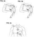
- FIG. 6a illustrates an embodiment of the invention with an intention transducer unit 5 in the form of a wearable controller 24 that is fixed on the healthy limb through forearm-mounted braces 25.
- the rigid orthosis 9 is adapted to embed wiring and allow the placement of electrodes on the patient's back.
- the orthosis contains the wiring necessary to provide electrical connectivity between the wearable controller 24 and the electrodes 1 , which are embedded into a supporting adhesive patch 11.
- Said adhesive patch 11 maintains the system in the desired positions and includes wiring to connect the electrodes.
- the wearable controller 24 communicates wirelessly with at least one electrical stimulator 2 wired to stimulation electrodes 1.
- FIG. 6b illustrates an embodiment according to the invention of the wearable movement controller 24 having forearm-mounted braces 25, and adjustable length in order to be fixed on patients having different forearm length. Furthermore, the part with adjustable length 43 allows the user to displace the movement controller 24 , freeing the healthy hand for use.
- Said wearable movement controller 24 has buttons 60 that allow users to select the desired movement with the thumb and a rotating knob 61 that allows users to modulate the selected movement according to their will.
- Said rotating knob 61 acts as rotating knob 8 shown in FIG. 2a and 2b .
- FIG. 6c illustrates a construction where the healthy arm weight is supported through a locking system 26 adapted to mechanically stabilize the relative angle between the proximal and distal portions of the arm. Said locking system 26 is fixed to the body through arm-braces 25.
- the rigid orthosis 9 and locking system 26 are adapted to constrain and to support the healthy limb, thus avoiding postural fatigue. Moreover, the orthosis internally contains the appropriate wiring to provide electrical connectivity between the wearable controller 24 and the electrodes 1 , which are embedded into a supporting adhesive patch 11 that maintains the electrodes in the desired positions and includes wiring to connect the electrodes.
- FIG. 6d further illustrates a construction of a 2-states adjustable locking mechanism 26 either allowing rotations of the elbow joint or providing mechanical support against gravity.
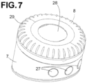
- FIG. 7 illustrates how an intention transducing unit 5 , in the form of a rotating knob 8 , is embedded into a cylindrical casing 7 comprising the controller unit 3. Said rotating knob 8 was also illustrated in FIG. 2a, 2b , 6c .
- Buttons 27 located on the side walls of the cylindrical casing 7 allow the user to select the desired action. Buttons 27 also allows switching on and off the device and select additional functionalities offered by the device and visualized on the screen 28.
- knob 8 is transformed into an electrical signal by means of a mechanical to electrical signal transducer, for example a rotary encoder, magnetic encoder or optical device. Such signal is transmitted to the controller unit 3.
- a mechanical to electrical signal transducer for example a rotary encoder, magnetic encoder or optical device. Such signal is transmitted to the controller unit 3.
- the knob 8 can include parts in relief 29 to facilitate handling and rotation of the knob, especially for elderly users.
- the controller unit 3 is connected to an internal or external electrical stimulator 2. In the case of embedding an internal electrical stimulator 2 the controller unit 3 is connected through a multichannel plug to the electrodes 1 .
- the intention transducing unit 5 provides connectivity to external devices through wires or wirelessly.
- the intention transducing unit 5 is powered by a rechargeable battery embedded in the cylindrical casing 7.
- the battery can be recharged through the power plug.
- the controller unit 3 comprises a microcontroller or microprocessor to perform internal computation and drive the electrical stimulator 2 , transforming signals received from intention transducing unit 5 to input signals for the electrical stimulator 2.
- FIG. 8 a illustrates an electrodes support 21 manufactured to embed and correctly place on the body electrodes 44 and 45.
- FIG. 8b clarifies the muscles electrically stimulated by the electrodes embedded in adhesive support 21.
- Electrode support 21 is adapted to maintain electrode 44 fixed on top of the ventral, proximal side of the biceps brachii muscle 30 , also involving the brachialis muscle 31 (to obtain elbow flexion and supination); and electrode 45 on the distal extremity of the flexor digitorum superficialis muscle 32 (to obtain fingers flexion and palmar hand grasping). Electricity is injected through bipolar montage over electrodes 44 and 45 as to jointly stimulate biceps and fingers flexor muscles.
- Electrodes 44 and 45 allow stimulation with electrical currents, for example with a rectangular waveform, wherein said waveform has a frequency between 15 and 60 Hz, a pulse width between 150 and 500us and a current intensity between 0 and 50 mA to induce harmonious movement to grasp and bring objects located in front of the body to the mouth, as shown in FIG. 8c (starting position), FIG. 8d (intermediate position) and FIG. 8e (final position).
- the electrical connectivity between electrodes 44 and 45 is ensured by a generic stimulation or sensing connection wire 62 embedded into the adhesive support 21.
- Electrode support 21 comprises a narrow adhesive section 33 running on the posterior side of the forearm, over the line defined by the ulna bone connecting the elbow to the wrist joints.
- Adhesive section 33 maintaining the generic stimulation or sensing connection wire 62 attached to the arm, prevents it from being unwillingly pulled during the execution of daily life actions.
- the support can be connected to the electrical stimulator 2 by means of a generic stimulation or sensing multi-channel plug 63.
- FIG. 9 a illustrates an electrodes support 21 manufactured to embed and correctly place on the body electrodes 46 and 47.
- FIG. 9b clarifies the muscles electrically stimulated by the electrodes embedded in support 21.
- Electrodes support 21 is adapted to maintain electrode 47 on the proximal extremity of the extensor indicis cavem muscle 34 and electrode 46 on the distal extremity of the extensor indicis cavem muscle 34 (to obtain index extension). Electricity is injected through bipolar montage over electrodes 46 and 47 as to stimulate the extensor indicis veinm muscle.
- Electrode 46 and 47 allow stimulation with electrical currents, for example with a rectangular waveform, wherein said waveform has a frequency between 15 and 60 Hz, a pulse width between 150 and 500us and a current intensity between 0 and 40 mA to induce harmonious movement to extend the index and point at objects located everywhere in space.
- FIG. 9c shows the starting position of the action
- FIG. 9d the ending position resulting in the execution of the action.
- FIG. 10a, 10c and 10 d illustrate electrode supports 21a and 21b manufactured to embed and correctly place on the body electrodes 44, 45, 48, 49.
- FIG. 10b clarifies the muscles electrically stimulated by the electrodes embedded in support 21a.
- One electrode support 21a is adapted to maintain electrode 44 on the ventral, proximal side of the biceps brachii muscle 30 , also involving the brachialis muscle 31 (to obtain elbow flexion and supination) and electrode 45 on the flexor digitorum superficialis muscle 32 (to obtain fingers flexion and palmar hand grasping). Electricity is injected through bipolar montage over electrodes 44 and 45 as to separately stimulate the biceps and fingers flexor muscles.
- Another electrode support 21b is adapted to maintain electrode 48 on the distal extremity of the subspinous fossa 35 and another electrode 49 on the proximal extremity of the subspinous fossa 35 (to obtain external shoulder rotation). Electricity is injected through bipolar montage over electrodes 48 and 49.
- Electrodes 44 and 45 allow stimulation with electrical currents, for example with a frequency between 15 and 60 Hz, a pulse width between 150us and 500us and a current intensity between 0 and 50 mA.
- Electrodes 48 and 49 allow stimulation with electrical currents, for example with a frequency between 15 and 60 Hz, a pulse width between 150us and 500us and a current intensity between 0 and 60 mA.
- the electrical parameters of currents applied on electrodes 44 , 45 , 48 , 49 are designed to induce harmonious movement to pass objects from a position in front of the body to a position far from the body, on the same hemi-space of the stimulated limb as shown in FIG. 10e (starting position) and FIG. 10f (final position).
- Electrode supports 21a might comprise a narrow adhesive section 33a running on the posterior side of the elbow between the lateral epicondyle and the olecranon.
- Adhesive section 33a maintaining the generic stimulation or sensing connection wire 62 attached to the arm, prevents it from being unwillingly pulled during the execution of daily life actions.
- Electrode support 21b might comprise an elongated adhesive portion 33b running over the acromion stabilizing support 21b and allowing prolonged usage during the day.
- Electrical connectivity between the electrical stimulator 2 and the electrodes support 21a is allowed by wiring connected to generic stimulation or sensing multi-channel plug 63a. Electrical connectivity to the electrode support 21b is established by connecting the generic stimulation or sensing multi-channel plug 63b by means of proper wiring.
- FIG. 11 a illustrates electrode supports 21a and 21b manufactured to embed and correctly place on the body electrodes 44 , 50 , 51 , 52 , 53 , 54.
- FIG. 11b clarifies the muscles electrically stimulated by the electrodes embedded in supports 21a and 21b.
- One Electrode support 21 a is adapted to maintain electrode 44 on the ventral, proximal side of the biceps brachii muscle 30 , also involving the brachialis muscle 31 (to obtain elbow flexion and supination) and another electrode 50 on the lateral side of the on the flexor digitorum superficialis muscle 32 (to obtain fingers flexion and palmar hand grasping). Electricity is injected through bipolar montage over electrodes 44 and 50 as to jointly stimulate the biceps and fingers flexor muscles.
- Another electrode support 21b is adapted to maintain electrode 51 on the distal extremity of the pectoralis minor 36 , electrode 52 on the ventral portion of the pectoralis major 37 in correspondence of the ventral part of the underlying pectoralis minor 36 (to obtain internal shoulder rotation and arm flexion crossing the median plane), electrode 53 on the ventral portion of the deltoid muscle 38 and electrode 54 on the lateral proximal side of the deltoid muscle 38 , below the clavicle (to support internal shoulder rotation and arm flexion on the median plane). Electricity is injected through a bipolar montage over electrodes 51 , 52 and 53 , 54 as to separately stimulate the pectoralis and deltoid muscles.
- Electrodes 44 , 50 , 51 , 52 , 53 , 54 allow stimulation with electrical currents, for example with a rectangular waveform, wherein said waveform has a frequency between 15 and 60 Hz, a pulse width between 150us and 500us and a current intensity between 0 to 60 mA.
- the electrical parameters of currents applied on electrodes 44 , 50 , 51 , 52 , 53 , 54 are designed to induce a harmonious movement to pass objects from a position in front of the body to a position far away towards the opposite side of the body as shown in FIG. 11c (starting position) and FIG. 11d (final position).
- Electrode support 21a comprises one narrow adhesive section 33a running from the pectoralis major 37 towards the shoulder.
- Adhesive section 33a has a shape adapted to fit and hold to the clavicle, ensuring that the placement of electrode support 21a is stable during complex movements.
- Another electrode support 21b comprises one narrow adhesive section 33b running from the shoulder to the armpit. Adhesive section 33b, maintains wiring between electrode support 21b attached to the arm, preventing it from being unwillingly pulled during the execution of daily life actions.
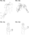
- FIG. 12 a illustrates electrode supports 21 manufactured to embed and correctly place on the body electrodes 53 , 54 , 55 , 56 , 57 , 58.
- FIG. 12b clarifies the muscles electrically stimulated by the electrodes embedded in support 21.
- One electrode support 21 is adapted to maintain electrode 55 on the distal portion of the flexor pollicis longus muscle 39 , electrode 56 on the ventral portion of the flexor digitorum superficialis muscle 32 (to obtain finger flexion into a palm and thumb grasp).
- Another electrode support 21 is adapted to maintain electrode 54 on the ventral, distal side of the deltoid 38 , electrode 57 on the distal extremity of the deltoid 38 (to obtain arm flexion on the median plane), electrode 53 on the ventral portion of the deltoid 38 , electrode 58 on the distal extremity of the pectoralis major 37 , under the clavicle (to support and stabilize arm rotation). Electricity is injected through bipolar montages over electrodes 53 , 57 and 55 , 56 and 54 , 58 as to separately stimulate fingers flexors , pectoralis and deltoid muscles.
- Electrodes 53 , 54 , 55 , 56 , 57 , 58 allow stimulation with electrical currents, for example with a rectangular waveform, wherein said waveform has a frequency between 15 and 60 Hz, a pulse width between 150us and 500us and a current intensity between 0 and 50 mA.
- the electrical parameters of currents applied on electrodes 53 , 54 , 55 , 56 , 57 , 58 are designed to induce a harmonious movement to grasp an object in front of the subject and lift it on its median plane, frontally as shown in FIG. 12c (starting position) and FIG. 12d (final position).
- FIG. 13 shows several electrodes supports 21 adapted to embed electrodes 1 according to their spatial proximity on the body, in one of the embodiments of the invention.
- Electrodes supports 21 Embedding the electrodes supports 21 on a surface according to their spatial proximity reduces the number of patches to be applied to the body, thus increasing the ease-of-use of this embodiment of the invention.
- the casing 12 embeds the controller unit 3 and the electrical stimulator 2 .
- the controller unit 3 is adapted to receive wirelessly stimulation commands from a master controller 13 .
- the master controller 13 collects and processes data from body tracking system, for example a 3D camera-based tracking system 14 .
- FIG. 14 a shows the application of the conductive polymer 40 on the skin of a user by using a marker 41 .
- conductive polymer can be realized for example using silicon-derived fast curing polymers mixed with conductive particles, for example carbon particles, metal particles or other bio-compatible conductive particles or small conductive structures.
- the polymer can have other properties to facilitate detachment, as for example being washable or degrade autonomously after a defined number of hours.
- the marker 41 is only one possible way to apply the polymer on the skin, other examples includes brushes or pencils.
- Fig. 14b shows the insertion of a conductive lead 42 into the conductive polymer providing connection to the electrical stimulator.
- Fig. 14c shows the final cured electrode after the conductive polymer 40 solidified and embedded the lead 42 .
- movements of one side of the body are replicated on the other side of the body, allowing mirror-like replication of movements.
- the body tracking system can be implemented with wearable gyroscopes or accelerometers adapted to communicate with the master controller 13 .
- the master controller 13 broadcasts stimulation commands to every controller unit 3 in range, replicating the tracked movements of a target user 15 on all other users in range 16 .
Claims (5)
- Dispositif neuroprothétique permettant de restaurer des mouvements d'action quotidienne d'un membre supérieur chez un patient souffrant d'une déficience motrice, ledit dispositif comprenant plusieurs électrodes non invasives (1, 44-57) conçues pour être fixées sur la partie supérieure du corps du patient, de manière à stimuler au moins deux muscles distincts (30-32, 34-39, 58, 59) qui participent à l'exécution des mouvements dudit membre supérieur,un dispositif de stimulation électrique (2) pour injecter un courant électrique dans lesdites électrodes (1, 44-57) etune unité de commande (3) pour réguler lesdits courants à travers lesdites électrodes (1, 44-57),l'unité de commande (3) comprenant une unité de transduction d'intention (5) conçue pour convertir un courant d'entrée régulé par ledit patient en une pluralité de courants électriques (6) pour générer et moduler ladite exécution de mouvement,caractérisé par le fait quel'unité de transduction d'intention sert également de moyens de contrainte (25) pour le membre sain qui l'actionne, les moyens de contrainte (25) étant configurés pour contraindre les mouvements ou immobiliser une partie d'un membre supérieur sain du patient, les moyens de contrainte (25) étant en outre configurés pour permettre une mobilité suffisante d'une main du membre supérieur sain du patient pour actionner l'unité de transduction d'intention (5),et par le fait que les moyens de contrainte sont des attelles (25) montées sur l'avant-bras.
- Dispositif selon la revendication 1, comprenant une orthèse rigide (9).
- Dispositif selon l'une des revendications précédentes, dans lequel l'unité de transduction d'intention (5) comprend un bouton rotatif (8, 61).
- Dispositif tel que défini dans l'une des revendications précédentes, dans lequel l'unité de transduction d'intention (5) a la forme d'un dispositif de commande à porter sur soi (24) fixé sur le membre sain par l'intermédiaire desdites attelles montées sur l'avant-bras (25).
- Dispositif selon la revendication 4, dans lequel ledit dispositif de commande de mouvement à porter sur soi (24) comprend une partie à longueur réglable (43) afin d'être fixé sur des patients ayant une longueur d'avant-bras différente, ladite partie à longueur réglable (43) permettant à l'utilisateur de déplacer le dispositif de commande de mouvement (24) ce qui libère la main saine en vue d'une utilisation.
Applications Claiming Priority (2)
| Application Number | Priority Date | Filing Date | Title |
|---|---|---|---|
| IB2013059574 | 2013-10-23 | ||
| PCT/IB2014/065417 WO2015059612A1 (fr) | 2013-10-23 | 2014-10-17 | Système de neuroprothèse pour restaurer la fonction d'un membre supérieur par l'intermédiaire d'une stimulation électrique coordonnée |
Publications (2)
| Publication Number | Publication Date |
|---|---|
| EP3060113A1 EP3060113A1 (fr) | 2016-08-31 |
| EP3060113B1 true EP3060113B1 (fr) | 2024-04-03 |
Family
ID=51945952
Family Applications (1)
| Application Number | Title | Priority Date | Filing Date |
|---|---|---|---|
| EP14802174.4A Active EP3060113B1 (fr) | 2013-10-23 | 2014-10-17 | Système de neuroprothèse pour restaurer la fonction d'un membre supérieur par l'intermédiaire d'une stimulation électrique coordonnée |
Country Status (3)
| Country | Link |
|---|---|
| US (1) | US10046161B2 (fr) |
| EP (1) | EP3060113B1 (fr) |
| WO (1) | WO2015059612A1 (fr) |
Families Citing this family (10)
| Publication number | Priority date | Publication date | Assignee | Title |
|---|---|---|---|---|
| CN108348746B (zh) | 2015-09-23 | 2021-10-12 | 卡拉健康公司 | 用于手指或手中的周围神经刺激以治疗手震颤的系统和方法 |
| US11344722B2 (en) | 2016-01-21 | 2022-05-31 | Cala Health, Inc. | Systems, methods and devices for peripheral neuromodulation for treating diseases related to overactive bladder |
| CN107088264A (zh) * | 2016-02-18 | 2017-08-25 | 代丁 | 强制性再学习电刺激康复训练系统及训练方法 |
| ITUB20161073A1 (it) * | 2016-02-25 | 2017-08-25 | Federico Pleitavino | Apparecchiatura per la riabilitazione fisica |
| US10905617B2 (en) * | 2016-12-19 | 2021-02-02 | Intel Corporation | Wearable assistive jamming apparatus and related methods |
| US11857778B2 (en) | 2018-01-17 | 2024-01-02 | Cala Health, Inc. | Systems and methods for treating inflammatory bowel disease through peripheral nerve stimulation |
| CN110694169A (zh) * | 2019-09-16 | 2020-01-17 | 浙江大学 | 基于运动意图诱发中枢神经系统微电刺激的运动功能障碍神经桥接系统 |
| US11890468B1 (en) | 2019-10-03 | 2024-02-06 | Cala Health, Inc. | Neurostimulation systems with event pattern detection and classification |
| CN111167013A (zh) * | 2020-01-07 | 2020-05-19 | 温州医科大学附属第二医院、温州医科大学附属育英儿童医院 | 脑中风侧上肢功能性电刺激按摩臂套 |
| RU202855U1 (ru) * | 2020-08-20 | 2021-03-11 | Мустафа Халилович Аль-Замиль | Устройство для электронейростимуляции |
Family Cites Families (15)
| Publication number | Priority date | Publication date | Assignee | Title |
|---|---|---|---|---|
| US4582049A (en) | 1983-09-12 | 1986-04-15 | Ylvisaker Carl J | Patient initiated response method |
| US4558704A (en) | 1983-12-15 | 1985-12-17 | Wright State University | Hand control system |
| US5167229A (en) | 1986-03-24 | 1992-12-01 | Case Western Reserve University | Functional neuromuscular stimulation system |
| US20040044381A1 (en) * | 2000-08-14 | 2004-03-04 | Duncan Michael Robert | Muscle fatigue meter |
| US7497806B2 (en) | 2000-08-14 | 2009-03-03 | Neopraxis Pty Ltd. | Exercise apparatus for a person with muscular deficiency |
| AUPQ941300A0 (en) * | 2000-08-14 | 2000-09-07 | Neopraxis Pty Ltd | Interface to fes control system |
| JP2002200104A (ja) * | 2000-12-28 | 2002-07-16 | Japan Science & Technology Corp | 短下肢装具併用ハイブリッドfes装置 |
| US6701189B2 (en) | 2001-03-30 | 2004-03-02 | Neurocontrol Corporation | Systems and methods for performing prosthetic or therapeutic neuromuscular stimulation using a universal external controller accommodating different control inputs and/or different control outputs |
| WO2002085452A1 (fr) | 2001-04-24 | 2002-10-31 | Neurodan A/S | Systeme de therapie electrique fonctionnelle (fets) |
| US20070179560A1 (en) | 2002-10-23 | 2007-08-02 | Kai-Yu Tong | Functional electrical stimulation system |
| US7725175B2 (en) | 2002-12-04 | 2010-05-25 | Kinetic Muscles, Inc. | System and method for neuromuscular reeducation |
| DE102006058346A1 (de) | 2006-12-11 | 2008-06-19 | Lohmann & Rauscher GmbH, Schönau | Vorrichtung zur transkutanen elektrischen Stimulation motorischer und/oder sensorischer Nerven |
| JP4220567B1 (ja) | 2007-08-27 | 2009-02-04 | 本田技研工業株式会社 | 運動補助システム |
| WO2009051638A1 (fr) | 2007-10-16 | 2009-04-23 | Medtronic, Inc. | Commande de thérapie selon un état de mouvement de patient |
| JP5569885B2 (ja) | 2011-10-28 | 2014-08-13 | 学校法人加計学園 | 足関節駆動による歩行支援機能的電気刺激システム |
-
2014
- 2014-10-17 WO PCT/IB2014/065417 patent/WO2015059612A1/fr active Application Filing
- 2014-10-17 EP EP14802174.4A patent/EP3060113B1/fr active Active
- 2014-10-17 US US15/029,704 patent/US10046161B2/en active Active
Also Published As
| Publication number | Publication date |
|---|---|
| EP3060113A1 (fr) | 2016-08-31 |
| WO2015059612A1 (fr) | 2015-04-30 |
| US20160303369A1 (en) | 2016-10-20 |
| US10046161B2 (en) | 2018-08-14 |
Similar Documents
| Publication | Publication Date | Title |
|---|---|---|
| EP3060113B1 (fr) | Système de neuroprothèse pour restaurer la fonction d'un membre supérieur par l'intermédiaire d'une stimulation électrique coordonnée | |
| Rupp et al. | Functional rehabilitation of the paralyzed upper extremity after spinal cord injury by noninvasive hybrid neuroprostheses | |
| Marquez-Chin et al. | Functional electrical stimulation therapy for restoration of motor function after spinal cord injury and stroke: a review | |
| Bockbrader et al. | Brain computer interfaces in rehabilitation medicine | |
| Malešević et al. | A multi-pad electrode based functional electrical stimulation system for restoration of grasp | |
| US9108060B2 (en) | Neural prosthesis | |
| Schultz et al. | Neural interfaces for control of upper limb prostheses: the state of the art and future possibilities | |
| Peckham et al. | Challenges and opportunities in restoring function after paralysis | |
| US20060167564A1 (en) | Limb and digit movement system | |
| Micera et al. | Wearable neural prostheses | |
| Mikołajewska et al. | Neuroprostheses for increasing disabled patients’ mobility and control | |
| Triolo et al. | Challenges to clinical deployment of upper limb neuroprostheses | |
| Morel et al. | Long-term decoding of movement force and direction with a wireless myoelectric implant | |
| Rupp et al. | Neuroprosthetics of the upper extremity—clinical application in spinal cord injury and challenges for the future | |
| Pan et al. | Evoking haptic sensations in the foot through high-density transcutaneous electrical nerve stimulations | |
| Wang et al. | Real-time and wearable functional electrical stimulation system for volitional hand motor function control using the electromyography bridge method | |
| US20190091472A1 (en) | Non-invasive eye-tracking control of neuromuscular stimulation system | |
| JP2021514774A (ja) | 非侵襲的な神経刺激 | |
| Bryden et al. | An implanted neuroprosthesis for high tetraplegia | |
| Kilgore | Sensors for motor neuroprostheses | |
| WO2017205476A1 (fr) | Commande non effractive de suivi oculaire destinée à un système de stimulation neuromusculaire | |
| Agnello | New-generation fully programmable controller for functional electrical stimulation applications | |
| Rupp | Neuroprosthetics | |
| Munih et al. | Current status and future prospects for upper and lower extremity motor system neuroprostheses | |
| Salchow-Hömmen et al. | Adaptive hand neuroprosthesis using inertial sensors for real-time motion tracking |
Legal Events
| Date | Code | Title | Description |
|---|---|---|---|
| PUAI | Public reference made under article 153(3) epc to a published international application that has entered the european phase |
Free format text: ORIGINAL CODE: 0009012 |
|
| 17P | Request for examination filed |
Effective date: 20160520 |
|
| AK | Designated contracting states |
Kind code of ref document: A1 Designated state(s): AL AT BE BG CH CY CZ DE DK EE ES FI FR GB GR HR HU IE IS IT LI LT LU LV MC MK MT NL NO PL PT RO RS SE SI SK SM TR |
|
| AX | Request for extension of the european patent |
Extension state: BA ME |
|
| DAX | Request for extension of the european patent (deleted) | ||
| RIN1 | Information on inventor provided before grant (corrected) |
Inventor name: MAESANI, ANDREA Inventor name: DIMASSI, HEDI Inventor name: BIASIUCCI, ANDREA |
|
| STAA | Information on the status of an ep patent application or granted ep patent |
Free format text: STATUS: EXAMINATION IS IN PROGRESS |
|
| 17Q | First examination report despatched |
Effective date: 20181025 |
|
| STAA | Information on the status of an ep patent application or granted ep patent |
Free format text: STATUS: EXAMINATION IS IN PROGRESS |
|
| REG | Reference to a national code |
Ref country code: DE Ref legal event code: R079 Ref document number: 602014089840 Country of ref document: DE Free format text: PREVIOUS MAIN CLASS: A61B0005048800 Ipc: A61N0001360000 Free format text: PREVIOUS MAIN CLASS: A61B0005048800 |
|
| GRAP | Despatch of communication of intention to grant a patent |
Free format text: ORIGINAL CODE: EPIDOSNIGR1 |
|
| STAA | Information on the status of an ep patent application or granted ep patent |
Free format text: STATUS: GRANT OF PATENT IS INTENDED |
|
| RIC1 | Information provided on ipc code assigned before grant |
Ipc: A61F 2/72 20060101ALI20231012BHEP Ipc: A61N 1/36 20060101AFI20231012BHEP |
|
| INTG | Intention to grant announced |
Effective date: 20231026 |
|
| GRAS | Grant fee paid |
Free format text: ORIGINAL CODE: EPIDOSNIGR3 |
|
| GRAA | (expected) grant |
Free format text: ORIGINAL CODE: 0009210 |
|
| STAA | Information on the status of an ep patent application or granted ep patent |
Free format text: STATUS: THE PATENT HAS BEEN GRANTED |
|
| AK | Designated contracting states |
Kind code of ref document: B1 Designated state(s): AL AT BE BG CH CY CZ DE DK EE ES FI FR GB GR HR HU IE IS IT LI LT LU LV MC MK MT NL NO PL PT RO RS SE SI SK SM TR |
|
| REG | Reference to a national code |
Ref country code: GB Ref legal event code: FG4D |