EP3060100B1 - System and method for obtaining bodily function measurements using a mobile device - Google Patents
System and method for obtaining bodily function measurements using a mobile device Download PDFInfo
- Publication number
- EP3060100B1 EP3060100B1 EP14793968.0A EP14793968A EP3060100B1 EP 3060100 B1 EP3060100 B1 EP 3060100B1 EP 14793968 A EP14793968 A EP 14793968A EP 3060100 B1 EP3060100 B1 EP 3060100B1
- Authority
- EP
- European Patent Office
- Prior art keywords
- measurement
- mobile device
- user
- sensors
- obtaining
- Prior art date
- Legal status (The legal status is an assumption and is not a legal conclusion. Google has not performed a legal analysis and makes no representation as to the accuracy of the status listed.)
- Active
Links
Images


Classifications
-
- A—HUMAN NECESSITIES
- A61—MEDICAL OR VETERINARY SCIENCE; HYGIENE
- A61B—DIAGNOSIS; SURGERY; IDENTIFICATION
- A61B5/00—Measuring for diagnostic purposes; Identification of persons
- A61B5/02—Detecting, measuring or recording for evaluating the cardiovascular system, e.g. pulse, heart rate, blood pressure or blood flow
- A61B5/021—Measuring pressure in heart or blood vessels
-
- A—HUMAN NECESSITIES
- A61—MEDICAL OR VETERINARY SCIENCE; HYGIENE
- A61B—DIAGNOSIS; SURGERY; IDENTIFICATION
- A61B5/00—Measuring for diagnostic purposes; Identification of persons
- A61B5/0059—Measuring for diagnostic purposes; Identification of persons using light, e.g. diagnosis by transillumination, diascopy, fluorescence
-
- A—HUMAN NECESSITIES
- A61—MEDICAL OR VETERINARY SCIENCE; HYGIENE
- A61B—DIAGNOSIS; SURGERY; IDENTIFICATION
- A61B5/00—Measuring for diagnostic purposes; Identification of persons
- A61B5/02—Detecting, measuring or recording for evaluating the cardiovascular system, e.g. pulse, heart rate, blood pressure or blood flow
- A61B5/02028—Determining haemodynamic parameters not otherwise provided for, e.g. cardiac contractility or left ventricular ejection fraction
-
- A—HUMAN NECESSITIES
- A61—MEDICAL OR VETERINARY SCIENCE; HYGIENE
- A61B—DIAGNOSIS; SURGERY; IDENTIFICATION
- A61B5/00—Measuring for diagnostic purposes; Identification of persons
- A61B5/02—Detecting, measuring or recording for evaluating the cardiovascular system, e.g. pulse, heart rate, blood pressure or blood flow
- A61B5/021—Measuring pressure in heart or blood vessels
- A61B5/02108—Measuring pressure in heart or blood vessels from analysis of pulse wave characteristics
- A61B5/02125—Measuring pressure in heart or blood vessels from analysis of pulse wave characteristics of pulse wave propagation time
-
- A—HUMAN NECESSITIES
- A61—MEDICAL OR VETERINARY SCIENCE; HYGIENE
- A61B—DIAGNOSIS; SURGERY; IDENTIFICATION
- A61B5/00—Measuring for diagnostic purposes; Identification of persons
- A61B5/02—Detecting, measuring or recording for evaluating the cardiovascular system, e.g. pulse, heart rate, blood pressure or blood flow
- A61B5/024—Measuring pulse rate or heart rate
- A61B5/02416—Measuring pulse rate or heart rate using photoplethysmograph signals, e.g. generated by infrared radiation
-
- A—HUMAN NECESSITIES
- A61—MEDICAL OR VETERINARY SCIENCE; HYGIENE
- A61B—DIAGNOSIS; SURGERY; IDENTIFICATION
- A61B5/00—Measuring for diagnostic purposes; Identification of persons
- A61B5/02—Detecting, measuring or recording for evaluating the cardiovascular system, e.g. pulse, heart rate, blood pressure or blood flow
- A61B5/026—Measuring blood flow
- A61B5/0261—Measuring blood flow using optical means, e.g. infrared light
-
- A—HUMAN NECESSITIES
- A61—MEDICAL OR VETERINARY SCIENCE; HYGIENE
- A61B—DIAGNOSIS; SURGERY; IDENTIFICATION
- A61B5/00—Measuring for diagnostic purposes; Identification of persons
- A61B5/05—Detecting, measuring or recording for diagnosis by means of electric currents or magnetic fields; Measuring using microwaves or radio waves
- A61B5/053—Measuring electrical impedance or conductance of a portion of the body
- A61B5/0537—Measuring body composition by impedance, e.g. tissue hydration or fat content
-
- A—HUMAN NECESSITIES
- A61—MEDICAL OR VETERINARY SCIENCE; HYGIENE
- A61B—DIAGNOSIS; SURGERY; IDENTIFICATION
- A61B5/00—Measuring for diagnostic purposes; Identification of persons
- A61B5/16—Devices for psychotechnics; Testing reaction times ; Devices for evaluating the psychological state
- A61B5/165—Evaluating the state of mind, e.g. depression, anxiety
-
- A—HUMAN NECESSITIES
- A61—MEDICAL OR VETERINARY SCIENCE; HYGIENE
- A61B—DIAGNOSIS; SURGERY; IDENTIFICATION
- A61B5/00—Measuring for diagnostic purposes; Identification of persons
- A61B5/24—Detecting, measuring or recording bioelectric or biomagnetic signals of the body or parts thereof
- A61B5/316—Modalities, i.e. specific diagnostic methods
- A61B5/318—Heart-related electrical modalities, e.g. electrocardiography [ECG]
- A61B5/332—Portable devices specially adapted therefor
-
- A—HUMAN NECESSITIES
- A61—MEDICAL OR VETERINARY SCIENCE; HYGIENE
- A61B—DIAGNOSIS; SURGERY; IDENTIFICATION
- A61B5/00—Measuring for diagnostic purposes; Identification of persons
- A61B5/48—Other medical applications
- A61B5/4869—Determining body composition
- A61B5/4875—Hydration status, fluid retention of the body
-
- A—HUMAN NECESSITIES
- A61—MEDICAL OR VETERINARY SCIENCE; HYGIENE
- A61B—DIAGNOSIS; SURGERY; IDENTIFICATION
- A61B5/00—Measuring for diagnostic purposes; Identification of persons
- A61B5/68—Arrangements of detecting, measuring or recording means, e.g. sensors, in relation to patient
- A61B5/6801—Arrangements of detecting, measuring or recording means, e.g. sensors, in relation to patient specially adapted to be attached to or worn on the body surface
- A61B5/6802—Sensor mounted on worn items
- A61B5/681—Wristwatch-type devices
-
- A—HUMAN NECESSITIES
- A61—MEDICAL OR VETERINARY SCIENCE; HYGIENE
- A61B—DIAGNOSIS; SURGERY; IDENTIFICATION
- A61B5/00—Measuring for diagnostic purposes; Identification of persons
- A61B5/68—Arrangements of detecting, measuring or recording means, e.g. sensors, in relation to patient
- A61B5/6801—Arrangements of detecting, measuring or recording means, e.g. sensors, in relation to patient specially adapted to be attached to or worn on the body surface
- A61B5/6813—Specially adapted to be attached to a specific body part
- A61B5/6824—Arm or wrist
-
- A—HUMAN NECESSITIES
- A61—MEDICAL OR VETERINARY SCIENCE; HYGIENE
- A61B—DIAGNOSIS; SURGERY; IDENTIFICATION
- A61B5/00—Measuring for diagnostic purposes; Identification of persons
- A61B5/68—Arrangements of detecting, measuring or recording means, e.g. sensors, in relation to patient
- A61B5/6887—Arrangements of detecting, measuring or recording means, e.g. sensors, in relation to patient mounted on external non-worn devices, e.g. non-medical devices
- A61B5/6898—Portable consumer electronic devices, e.g. music players, telephones, tablet computers
-
- A—HUMAN NECESSITIES
- A61—MEDICAL OR VETERINARY SCIENCE; HYGIENE
- A61B—DIAGNOSIS; SURGERY; IDENTIFICATION
- A61B5/00—Measuring for diagnostic purposes; Identification of persons
- A61B5/72—Signal processing specially adapted for physiological signals or for diagnostic purposes
- A61B5/7271—Specific aspects of physiological measurement analysis
- A61B5/7278—Artificial waveform generation or derivation, e.g. synthesizing signals from measured signals
-
- A—HUMAN NECESSITIES
- A61—MEDICAL OR VETERINARY SCIENCE; HYGIENE
- A61B—DIAGNOSIS; SURGERY; IDENTIFICATION
- A61B5/00—Measuring for diagnostic purposes; Identification of persons
- A61B5/74—Details of notification to user or communication with user or patient; User input means
- A61B5/742—Details of notification to user or communication with user or patient; User input means using visual displays
-
- A—HUMAN NECESSITIES
- A61—MEDICAL OR VETERINARY SCIENCE; HYGIENE
- A61M—DEVICES FOR INTRODUCING MEDIA INTO, OR ONTO, THE BODY; DEVICES FOR TRANSDUCING BODY MEDIA OR FOR TAKING MEDIA FROM THE BODY; DEVICES FOR PRODUCING OR ENDING SLEEP OR STUPOR
- A61M21/00—Other devices or methods to cause a change in the state of consciousness; Devices for producing or ending sleep by mechanical, optical, or acoustical means, e.g. for hypnosis
- A61M21/02—Other devices or methods to cause a change in the state of consciousness; Devices for producing or ending sleep by mechanical, optical, or acoustical means, e.g. for hypnosis for inducing sleep or relaxation, e.g. by direct nerve stimulation, hypnosis, analgesia
-
- A—HUMAN NECESSITIES
- A61—MEDICAL OR VETERINARY SCIENCE; HYGIENE
- A61M—DEVICES FOR INTRODUCING MEDIA INTO, OR ONTO, THE BODY; DEVICES FOR TRANSDUCING BODY MEDIA OR FOR TAKING MEDIA FROM THE BODY; DEVICES FOR PRODUCING OR ENDING SLEEP OR STUPOR
- A61M21/00—Other devices or methods to cause a change in the state of consciousness; Devices for producing or ending sleep by mechanical, optical, or acoustical means, e.g. for hypnosis
- A61M2021/0005—Other devices or methods to cause a change in the state of consciousness; Devices for producing or ending sleep by mechanical, optical, or acoustical means, e.g. for hypnosis by the use of a particular sense, or stimulus
- A61M2021/0088—Other devices or methods to cause a change in the state of consciousness; Devices for producing or ending sleep by mechanical, optical, or acoustical means, e.g. for hypnosis by the use of a particular sense, or stimulus modulated by a simulated respiratory frequency
Definitions
- aspects of the disclosure relate to mobile devices, and more particularly, a system and method for obtaining at least one bodily function measurement of a user operating a mobile device.
- Physiological measures of stress may be used to communicate to a user instructions to alter his/her behavior, e.g., taking a break, taking deep breaths, etc.
- Measures of hydration may be used by athletes or generally active individuals to ensure that they stay hydrated to maintain physical performance. Additionally, this information may be useful for individuals who work in hot or dry environments and must maintain proper hydration. Further, this information may be useful for elderly individuals whose sense of hydration is decreased and are more prone to becoming dehydrated.
- important bodily function measurements may include measurements of a user's blood pressure and/or hydration state.
- a user's blood pressure may be measured using a pulse-measuring device.
- Typical pulse-measuring devices use either photoplethysmography (PPG) or electrocardiography (ECG) to measure a user's pulse.
- PPG photoplethysmography
- ECG electrocardiography
- a user's systolic blood pressure or diastolic blood pressure may be determined using a combination of the PPG and ECG using a technique known as pulse transit time (PTT).
- PTT pulse transit time
- the systolic blood pressure, along with other inputs such as pulse rate variability (PRV) and galvanic skin response (GSR) may be useful in determining the user's physiological measures of stress.
- PRV pulse rate variability
- GSR galvanic skin response
- existing mobile device solutions for obtaining PPG measurements and ECG measurements can only obtain measurements for one or the other. That is, existing mobile device solutions can only obtain a PPG measurement or an ECG measurement, but not both.
- a user's hydration state may be determined by measuring a total body water amount using a bioelectric impedance analysis (BIA).
- BIA measurements are typically accurate and may fall within 200ml of the actual value when performed properly.
- existing solutions to measure BIA require professional equipment in a clinical setting.
- the few devices that exist to measure BIA outside of a clinical setting are not very mobile, e.g., they may not fit within a user's pocket or be integrated into another device that the user typically always has with them.
- EP 2 644 089 A1 (D1) describing a method for providing a blood pressure indicator of a person. Said method obtains multiple first detection signals from a non-invasive optical plethysmography sensor and multiple second detection signals from a non-invasive Electrocardiography sensor.
- a health monitoring module processes both detection signals to detect first and second points in time that correspond to arrivals of blood pulses and to peaks of QRS complexes respectively.
- the module calculates a blood pressure indicator in response to a timing difference between a single pair of first and second points in time that are associated with a same heartbeat.
- D2 EP 1 977 688 A2 which relates inter alia to a blood pressure monitoring apparatus and a method that can monitor a blood pressure of a subject using an electrocardiogram signal, a pulse wave signal and a body characteristic information of the subject.
- US 2010 160 793 A1 describing a biosignal measurement module that includes a biosignal measurement unit for measuring an electrocardiogram signal and a pulse signal of a subject, a pose detection unit for detecting a position of the biosignal measurement module and outputting position signals, and a .processing unit for receiving the electrocardiogram signal, the pulse signal, and the position signals.
- the processing unit generates a height variation parameter, which indicates the height difference between the position of the biosignal measurement module and a reference position, according to the position signals.
- it calculates a current pulse transit time according to the electrocardiogram signal and the pulse signal and compensates for the current pulse transit time according to the height variation parameter to obtain a compensated pulse transit time.
- the processing unit obtains a blood pressure signal according to the compensated pulse transit time.
- Certain embodiments are described that for obtaining at least one bodily function measurement of a user operating a mobile device.
- a mobile device for obtaining at least one bodily function measurement comprises an outer body sized to be portable for a user, a processor contained within the outer body, and a plurality of sensors physically coupled to the outer body for obtaining data accessible by the processor.
- One or more sensors of the sensors is configured to obtain a first measurement indicative of blood volume in response to a user action, wherein at least one of the sensors configured to obtain the first measurement is contained within a contact button coupled to the outer body.
- One or more of the sensors is configured to obtain a second measurement indicative of heart electrical activity in response to the user action.
- the processor is configured to facilitate generation of a blood pressure measurement based on the first measurement and the second measurement.
- the mobile device is configured to perform a primary function and a secondary function
- the processor is configured to facilitate generation of the blood pressure measurement as the secondary function of the mobile device.
- the first measurement indicative of blood volume comprises a photoplethysmography (PPG) measurement.
- PPG photoplethysmography
- the second measurement indicative of heart electrical activity comprises an electrocardiography (ECG) measurement.
- ECG electrocardiography
- the one or more of the sensors is configured to obtain the first measurement comprises at least one light sensor, and wherein the mobile device further comprises at least one light source and the at least one light sensor measures reflected light from the light source reflected off of blood vessels within a user of the mobile device to obtain the first measurement.
- the at least one light sensor includes an infrared (IR) light emitting diode (LED).
- IR infrared
- LED light emitting diode
- the one or more of the sensors is configured to obtain the second measurement indicative of heart electrical activity comprises at least a first electrode and a second electrode, and wherein a portion of a user of the mobile device's body completes a circuit between the first electrode and the second electrode.
- the mobile device is a watch.
- the mobile device is a smartphone device.
- method for obtaining at least one bodily function measurement via a mobile device comprises obtaining, via a plurality of sensors physically coupled to an outer body of the mobile device, a first measurement indicative of blood volume in response to a user action, wherein at least one of the sensors is contained within a contact button coupled to the outer body.
- the method further comprises obtaining, via the plurality of sensors, a second measurement indicative of heart electrical activity in response to the user action.
- the method also comprises facilitating, via a processor of the mobile device, generation of a blood pressure measurement based on the first measurement and the second measurement, wherein the processor is contained within the outer body of the mobile device, the outer body sized to be portable for the user.
- an apparatus for obtaining at least one bodily function measurement comprises means for obtaining, via a plurality of sensors physically coupled to an outer body of a mobile device, a first measurement indicative of blood volume in response to a user action, wherein at least one of the sensors is contained within a contact button coupled to the outer body.
- the method further comprises means for obtaining, via the plurality of sensors, a second measurement indicative of heart electrical activity in response to the user action.
- the method also comprises means for facilitating, via a processor of the mobile device, generation of a blood pressure measurement based on the first measurement and the second measurement, wherein the processor is contained within the outer body of the mobile device, the outer body sized to be portable for the user.
- one or more non-transitory computer-readable media storing computer-executable instructions for obtaining at least one bodily function measurement that, when executed, cause one or more computing devices included in a mobile device to obtain, via a plurality of sensors physically coupled to an outer body of the mobile device, a first measurement indicative of blood volume in response to a user action, wherein at least one of the sensors is contained within a contact button coupled to the outer body.
- the computer-executable instructions when executed, further cause the one or more computing devices included in a device to obtain, via the plurality of sensors, a second measurement indicative of heart electrical activity in response to the user action.
- the computer-executable instructions when executed, further cause the one or more computing devices included in a device to facilitate, via a processor of the mobile device, generation of a blood pressure measurement based on the first measurement and the second measurement, wherein the processor is contained within the outer body of the mobile device, the outer body sized to be portable for the user.
- a mobile device for obtaining at least one bodily function measurement comprises an outer body sized to be portable for a user, a processor contained within the outer body. and a plurality of sensors physically coupled to the outer body for obtaining data accessible by the processor.
- the plurality of sensors comprises electrodes and a portion of a user's body positioned between the electrodes completes a circuit and a measurement to provide at least one measure of impedance associated with the user's body in response to a user action.
- the processor is configured to facilitate generation of a hydration level measurement based on the measure of impedance.
- the mobile device is configured to perform a primary function and a secondary function
- the processor is configured to facilitate generation of the hydration level measurement as the secondary function of the mobile device.
- At least one of the sensors is built into a multifunction surface, wherein the multifunction surface is configured to simultaneously obtain the impedance measurement and a user input.
- the multifunction surface comprises silver metal.
- the multifunction surface comprises Indium Tin Oxide (ITO).
- ITO Indium Tin Oxide
- the mobile device is a watch.
- the mobile device is a smartphone device.
- a method for obtaining at least one bodily function measurement via a mobile device comprises obtaining, via a plurality of sensors comprising electrodes and physically coupled to an outer body of the mobile device, a measurement to provide at least one measure of impedance associated with a user's body in response to a user action, wherein a portion of the user's body positioned between the electrodes completes a circuit.
- the method also comprises facilitating, via a processor of the mobile device, generation of a hydration level measurement based on the measure of impedance, wherein the processor is contained within the outer body of the mobile device, the outer body sized to be portable for the user.
- an apparatus for obtaining at least one bodily function measurement via a mobile device comprises means for obtaining, via a plurality of sensors comprising electrodes and physically coupled to an outer body of the mobile device, a measurement to provide at least one measure of impedance associated with a user's body in response to a user action, wherein a portion of the user's body positioned between the electrodes completes a circuit.
- the apparatus further comprises means for facilitating, via a processor of the mobile device, generation of a hydration level measurement based on the measure of impedance, wherein the processor is contained within the outer body of the mobile device, the outer body sized to be portable for the user.
- one or more non-transitory computer-readable media storing computer-executable instructions for obtaining at least one bodily function measurement that, when executed, cause one or more computing devices included in a mobile device to obtain, via a plurality of sensors comprising electrodes and physically coupled to an outer body of the mobile device, a measurement to provide at least one measure of impedance associated with a user's body in response to a user action, wherein a portion of the user's body positioned between the electrodes completes a circuit.
- the computer-executable instructions when executed, further cause the one or more computing devices included in a device to facilitate, via a processor of the mobile device, generation of a hydration level measurement based on the measure of impedance, wherein the processor is contained within the outer body of the mobile device, the outer body sized to be portable for the user.
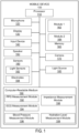
- FIG. 1 illustrates a simplified block diagram of a mobile device 100 that may incorporate one or more embodiments.
- Mobile device 100 includes a processor 110, microphone 120, display 130, input device 140, speaker 150, memory 160, camera 170, sensors 180, light source 185, and computer-readable medium 190.
- Processor 110 may be any general-purpose processor operable to carry out instructions on the mobile device 100.
- the processor 110 is coupled to other units of the mobile device 100 including microphone 120, display 130, input device 140, speaker 150, memory 160, camera 170, sensors 180, light source 185, and computer-readable medium 190.
- Microphone 120 may be any an acoustic-to-electric transducer or sensor that converts sound into an electrical signal.
- the microphone 120 may provide functionality for a user of the mobile device 100 to record audio or issue voice commands for the mobile device 100.
- Display 130 may be any device that displays information to a user. Examples may include an LCD screen, CRT monitor, or seven-segment display.
- Input device 140 may be any device that accepts input from a user. Examples may include a keyboard, keypad, or mouse. In some embodiments, the microphone 120 may also function as an input device 140.
- Speaker 150 may be any device that outputs sound to a user. Examples may include a built-in speaker or any other device that produces sound in response to an electrical audio signal and/or ultrasonic signal(s).
- Memory 160 may be any magnetic, electronic, or optical memory. Memory 160 includes two memory modules, module 1 162 and module 2 164. It can be appreciated that memory 160 may include any number of memory modules. An example of memory 160 may be dynamic random access memory (DRAM).
- DRAM dynamic random access memory
- Camera 170 is configured to capture one or more images via a lens located on the body of mobile device 100.
- the captured images may be still images or video images.
- the camera 170 may include a CMOS image sensor to capture the images.
- Various applications running on processor 110 may have access to camera 170 to capture images. It can be appreciated that camera 170 can continuously capture images without the images actually being stored within the mobile device 100. Captured images may also be referred to as image frames.
- Sensors 180 is a plurality of sensors configured to obtain data accessible by the processor.
- the sensors 180 is also physically coupled to the outer body of the mobile device 100.
- the plurality of sensors 180 may include one or more light sensors 182 and/or one or more electrodes 184.
- the light sensors 182 may be configured to facilitate measurement of reflected light from the light source 185 (described below) reflected off of blood vessels within a user of the mobile device 100 to obtain the a PPG measurement indicative of the user's blood volume.
- a portion of a user of the mobile device's 100 body may complete a circuit between a first electrode and a second electrode, e.g., when the user touches both electrodes 184.
- the electrodes 184 may be configured to facilitate measurement of heart electrical activity of the user to obtain an ECG measurement.
- the electrodes 184 may also be configured to facilitate measurement of impedance of the user of the mobile device 100 to obtain a level measurement.
- Light source 185 may be any source of light configured to emit light through a user's body.
- the light source 185 may be a LED light source.
- the emitted light may be of a wavelength that can pass through parts of a user's body.
- the light source 185 may emit LED light through a user's wrist.
- the mobile device 100 may include multiple light sources 185.
- the light emitted from light source 185 may reflect off of blood vessels within the user's body and the reflected light may be measured by one or more light sensors 182 to obtain a PPG measurement, as described above.
- emitted light may be of different wavelengths depending on different wavelengths. For example, different wavelengths of light may be appropriate to improve the signal, reduce noise, deal with dark skin colors, measure the blood's oxygen content, or penetrate to different depths of the user's body.
- Computer-readable medium 190 may be any magnetic, electronic, optical, or other computer-readable storage medium.
- Computer-readable storage medium 190 includes PPG measurement module 192, ECG measurement module 194, blood pressure measurement module 196, impedance measurement module 198, and hydration level measurement module 199.
- PPG measurement module 192 is configured to, when executed by processor 110, obtain a photoplethysmography (PPG) measurement.
- the PPG measurement may be a measurement of blood volume of a user operating the mobile device 100.
- the PPG measurement may be obtained by the PPG measurement module 192 in response to a user action.
- the PPG measurement module 192 may interface with the light source 185 and light sensors 182 in order to obtain the PPG measurement.
- the PPG measurement module 192 may direct the light source 185, or multiple light sources, to emit light through the user's body. As described above.
- the emitted light may reflect off or transmitted through blood vessels within the user's body and may be detected by one or more light sensors 182 within the mobile device 100.
- the PPG measurement module 192 may measure, by interfacing with the one or more light sensors, the amount of reflected or transmitted light detected by the one or more light sensors 182.
- the PPG measurement module 192 may then determine a PPG measurement that is indicative of the user's blood volume based on the measurement of the reflected light.
- ECG measurement module 194 is configured to, when executed by processor 110, obtain an electrocardiography (ECG) measurement.
- the ECG measurement may be a measurement of heart electrical activity of a user operating the mobile device 100.
- the ECG measurement may be obtained by the ECG measurement module 194 in response to a user action.
- the ECG measurement module 194 may interface with the electrodes 184 in order to obtain the ECG measurement.
- the ECG measurement module 194 may interface with the electrodes 184 to measure (assuming the user's body completes a circuit between the electrodes 184) electrical impulse(s) generated by the polarization and depolarization of cardiac tissue within the user's body.
- the electrical impulse(s) may be generated by the beating of the user's heart.
- the ECG measurement module 194 may interface with the electrodes 184 to measure the electrical impulse(s) automatically upon the user's body completing a circuit between the electrodes 184. The ECG measurement module 194 may then determine an ECG measurement based on the measured electrical impulse(s). It can be appreciated that ECG measurement can be obtained using two or more electrode leads.
- Blood pressure measurement module 196 is configured to, when executed by processor 110, generate a blood pressure measurement of the user based on the PPG measurement and the ECG measurement.
- a blood pressure measurement of the user based on the PPG measurement and the ECG measurement.
- Impedance measurement module 198 is configured to, when executed by processor 110, obtain an impedance measurement.
- the impedance measurement may be indicative of a hydration level of a user operating the mobile device 100.
- the impedance measurement may be obtained by the impedance measurement module 198 in response to a user action.
- impedance measurement module 198 may interface with the electrodes 184 in order to obtain the impedance measurement.
- the impedance measurement module 198 may interface with the electrodes 184 to measure (assuming the user's body completes a circuit between the electrodes 184) electrical impedance through the user's body.
- the impedance measurement module 198 may interface with the electrodes 184 to measure the electrical impedance automatically upon the user's body completing a circuit between the electrodes 184.
- Hydration level measurement module 199 is configured to, when executed by processor 110, obtain a hydration level measurement based on the impedance measurement obtained by the impedance measurement module 198.
- the hydration level measurement module 199 may determine the hydration level from the measured impedance using techniques well known in the art.
- the outer body of the mobile device 100 may be sized to be portable for a user.
- the term "portable” may refer to something that is able to be easily carried or moved, and may be a light and/or small.
- the term portable may refer to something easily transportable by the user or wearable by the user.
- the mobile device 100 may be a smartphone device or a watch wearable by the user.
- Other examples of portable devices include a head-mounted display, calculator, portable media player, digital camera, pager, personal navigation device, etc. Examples of devices that may not be considered portable include a desktop computer, traditional telephone, television, appliances, etc. It can be appreciated that the bodily function measurements can be obtained via the smartphone, watch, or any other of the mentioned devices.
- FIG. 2 illustrates a smartphone device 210 configured to obtain PPG and ECG measurements of a user, according to some embodiments.
- the smartphone device 210 is only one example of a mobile device 100.
- the smartphone device 210 may include a plurality of contacts 220. In some embodiments, a single contact 220 may be positioned at each end of the smartphone device 210.
- a device front surface 250 of the smartphone device 210 may include a contact layer including, e.g., silver metal or Indium Tin Oxide (ITO).
- ITO Indium Tin Oxide
- the smartphone device 210 may obtain both PPG and ECG measurements of the user 260.
- the device front surface 250 may be a touchscreen.
- the user 260 may hold the smartphone device 210 with his/her first hand 240 touching one or more of the contacts 220 and with his/her second hand 230 touching the device front surface 250.
- the contacts 220 and the contact layer of the device front surface 250 may complete a circuit through the user's 260 body.
- the smartphone device 210 may then measure an electrical potential through the completed circuit to determine the ECG measurement. It can be appreciated that the ECG measurement may also be obtained without the user's first hand 240 or second hand 230 contacting the device front surface 250. That is, the user's first hand 240 may make contact with a first side contact 220 and the user's second hand 230 may make contact with a second side contact 220 to complete the circuit.
- the user 260 may make contact with both side contacts 220 using only his/her first hand 240 or second hand 230 (see below for a measurement of PPG or Galvanic Skin Response (GSR)).
- sensors positioned and/or touched at other locations for example legs, feet, ankles, knees, elbows, arms, neck, head, etc. could also be used to generate PPG, GSR and possibly ECG, depending on the location and how the contact was made.
- the device front surface 250 of the smartphone device 210 may also obtain a PPG measurement of the user 260 by using an optical based technology. For example, when the user 260 touches the device front surface 250, a light source 185 may shine a light into the user's 260 skin, one or more sensors may measure the blood flow through the capillaries and thus determine a heart rate (PPG) of the user. This process is described in further detail below.
- the light source may be a dedicated light source that is part of the smartphone device 210.
- a PTT technique may be used to determine the user's blood pressure.
- the smartphone device 210 may then provide important information to the user 260, based on the determined blood pressure (described further below).
- the smartphone device 210 may obtain an impedance measurement of the user using BIA techniques.
- the impedance measurement may be obtained via the contact layer of the device front surface 250. The process of obtaining the impedance measurement is described in further detail below.
- the device front surface 250 serves multiple functions. That is, the device front surface 250 is used to obtain ECG, PPG, and/or impedance measurements as described above, and is also used as a user input device.
- the user 260 may use the device front surface 250 to provide input to applications being executed on the smartphone device 210.
- the user 260 may place the smartphone device 210 into a measurement mode.
- the smartphone device 210 may automatically detect the user's intention to obtain a bodily function measurement, e.g., from the user 260 placing his/her finger in a particular location on the device front surface 250 or touching the device front surface 250 for a predetermined period of time.
- the smartphone device 210 may regularly scan and store vital signs of the user 260 in the user's normal course of operating the device 210, without the user wanting or needed a particular vital sign report at that time.
- FIG. 3 illustrates a wristwatch device 310 configured to obtain PPG, ECG, and impedance measurements of a user, according to some embodiments.
- the wristwatch device 310 illustrated in FIG. 3 operates similarly to the smartphone device 210 in FIG. 2 . That is, the wristwatch device 310 may obtain PPG, ECG, and impedance measurements of the user 260 via a plurality of contacts. In some embodiments, one or more contacts may be placed at the bottom of the wristwatch device 310, where the contact makes a continuous contact with the user's 260 wrist while the user 260 wears the wristwatch device 310.
- the wristwatch device 310 also includes a multifunction button 320, which is used to obtain a bodily function measurement and also as a user input device.
- the multifunction button 320 may be used by the user 260 to set a date and/or time for the wristwatch device 310.
- the multifunction button may have an integrated electrode on the surface.
- the user 260 may also use the multifunction button 320 to obtain an ECG measurement by touching the button 320 to complete a circuit (via the other contacts) through the user's body.
- the multifunction button 320 may be integrated into a touchscreen of the wristwatch device 310.
- the PPG and hydration measurements may be obtained in a similar fashion as described with respect to the smartphone device of FIG. 2 , e.g., via the contacts on the wristwatch device 310.
- the PPG measurement may also be obtained using optical techniques, as described below.
- the wristwatch device 310 may be designed to be portable such that the user may easily wear the device or carry it on his/her person.
- the wristwatch device 310 may perform everyday functions other than obtaining PPG, ECG, and impedance measurements of the user.
- the wristwatch device 310 may provide the current time, a stopwatch function, a calendar function, communication functions, etc.
- the PPG, ECG, and impedance measurements functions may be available in addition to the other described functions on the wristwatch device 310.
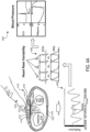
- FIG. 4A illustrates a cross sectional view 410 of the wristwatch device 310 of FIG. 3 and graphs 420, 430, and 440 showing measurements obtained by the wristwatch device, according to some embodiments.
- the cross sectional view 410 of the wristwatch device 310 shows a photodetector 412, a plurality of light emitting diodes (LED) 414, and a plurality of electrodes contacts 416. Additionally, the cross sectional view 410 also illustrates parts of a user's wrist, e.g., radial bone 418 and ulnar bone 419.
- the plurality of LEDs 414 can be infrared (IR) LEDs.
- the IR LEDs may provide advantages to the user, such as not distracting the user from normal operation of the wristwatch device 310 because the IR LEDs may not emit any visible light.
- the wristwatch device 310 may obtain PPG measurements of the user by using optical techniques.
- the LEDs 414 (typically positioned at the bottom of the wristwatch device 310 and on top of the user's wrist) may emit a light into the user's skin.
- the reflected light may be received at the photodetector 412.
- the user's blood volume may be determined based off of the reflected light as compared against time. From this data, the user's PPG measurement may be determined.
- the determination of the user's blood volume may be determined from a change in the user's blood volume. More specifically, a change in the diameter of the blood vessels that are being probed by the LEDs 414.
- the user's ECG measurement may be obtained using the plurality of contacts 416 as described above with respect to FIG. 3 .
- the plurality of contacts 416 may continuously be in contact with the user's skin while the user is wearing the wristwatch device 310 around his/her wrist. The user may then touch, with his/her hand that is not wearing the wristwatch device 310, another contact 416 that is located at another location on the wristwatch device 310 to complete the circuit through the user's body.
- the user's hydration measurements may also be obtained by using the plurality of contacts 416 and determining impedance through the user's body.
- Graph 420 illustrates the intensity of the obtained light reflections at the photodetector 412 against time.
- the duration between each pulse is approximately one second. From this graph, the user's PPG can be determined.
- Graph 430 shows a user's heart rate variability by comparing the user's ECG and the user's PPG.
- the PTT can be determined by taking the difference between a peak of an ECG pulse and the corresponding inflection point (at the same time interval) of the PPG pulse. The PTT may then be used to determine the user's blood pressure, which is well known in the art.
- FIG. 4B illustrates a cross sectional view of the wristwatch device 310 of FIG 3 . where the sensor for obtaining the PPG measurement is contained within a contact button of the wristwatch device, according to some embodiments.
- the wristwatch device 310 illustrated in FIG. 4B contains a PPG sensor 470 within a contact button 460 on the wristwatch device 310. The user may place his/her finger on the contact button 460 such that the PPG sensor 470 can obtain the PPG signal from the finger to determine the PPG measurement.
- the PPG sensor 470 may be an optical sensor.
- Certain advantages may be realized by placing the PPG sensor 470 within the contact button 460, including but not limited to, allowing for a faster and more accurate reading of the PPG signal from the user's finger as opposed to from the user's wrist. This can result in faster determination of the user's PTT. It can be appreciated that the PPG sensor 470 within the contact button 460 can provide better results than measuring the PPG from the arm/wrist due to the vascularization of the arm associated with obtaining the PPG measurement from the arm. That is, the arteries near the surface of the arm where the measurement is attempting to be obtained from can blur out the signal due to the high number of routes that blood cloud flow. However, in the finger, typically an artery runs along the inside between the user's fingers to the tip of the finger before expanding out into many capillaries. As such, a clear signal can be obtained from the finger.
- the contact button 460 may be a multi-function button operable to serve other functions of the wristwatch device 310.
- the multi-function button can be used to interact with the wristwatch device 310 for setting the time, starting/stopping a stopwatch, or any other function typically available in a wristwatch device 310.
- the wristwatch device 310 may also obtain an ECG measurement as described with respect to FIG. 4A , in accordance with some embodiments. That is, the ECG measurement can be obtained by the electrical contact 416 in contact with the user's arm/wrist and contact button 460 in contact with the user's finger, whereby the circuit is completed.
- the contact button 460 when the user touches his/her finger to the contact button 460, both the ECG measurement and the PPG measurement can be obtained.
- FIG. 4C illustrates a top view of the wristwatch device of FIG. 3 where the sensor for obtaining the PPG measurement is contained within a contact button of the wristwatch device, according to some embodiments.
- FIG. 4C illustrates the top view of the wristwatch device 310 described in FIG. 4B .
- the PPG sensor 470 is contained within the contact button 460.
- the electrical contact 416 used to obtain ECG measurement data can be located at the bottom of the wristwatch device 310.
- the contact button 460 may have an opening such that light from the PPG sensor 470 can travel through the opening to obtain an optical PPG measurement.
- the contact button 460 may made of a material that optimizes metal electrodes, such as stainless steel.
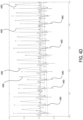
- FIG. 4D illustrates a graph showing heart activity measurements obtained from PPG measurements obtained at the finger, according to some embodiments.
- the graph shows an electrocardiogram signal 480 and a PPG signal 490 obtained at the finger of a 24-year old male.
- the PPG signal 490 does not contain much noise and the signal is smooth and/or rounded. Due to the better resolution of the PPG signal 490 provided by obtaining the measurement from the finger rather than the wrist, other information such as the heart activity can also benefit from the increased accuracy. Additional information that can be determined due to the better resolution of the PPG signal 490 can include, but is not limited to, systolic blood pressure and a measure of vascular stiffness.
- FIG. 5 is a schematic diagram 500 of a method for obtaining impedance measurements of a user, according to some embodiments.
- the mobile device may be either the smartphone device described in FIG. 2 , the wristwatch device described in FIG. 3 , or any other mobile device.
- the impedance measurement of the user may be used to determine the user's hydration level using BIA techniques.
- the user's body 510 essentially functions as a capacitance and resistance network in this illustration. When the user's body 510 makes contact with the contact points 530, an impedance converter 520 may determine the impedance value through the user's body 510. In this scenario, the user's body 510 may act as a capacitor.
- the impedance value may be a function of surface tissue impedance and deep tissue impedance.
- the impedance value may then be used to estimate a total body water content of the user's body 510.
- This figure shows measuring the impedance through one leg, the torso, and one arm. The method works the same way measuring through both arms and the chest.
- the mobile device may include phase-sensitive electronics to distinguish between electrical resistance and reactance.
- the mobile device may provide a notification to the user.
- the types of notifications are described in further detail with respect to FIG. 7 .
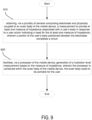
- FIG. 6 is a schematic diagram 600 of two resistors and a capacitor representing conduction through tissue, according to some embodiments.
- x c represents the capacitance of the user's cell walls
- R (ICW) represents the resistance of the body water inside of the user's cells
- R (ECW ) represents the resistance of the body water outside of the user's cells.
- the circuit shown in FIG. 6 may be used as part of the schematic diagram in FIG. 5 to determine the hydration level of the user by determining an electrical impedance through the user's body.
- FIG. 7 is a flow diagram 700 illustrating a plurality of derived metrics 720 from a plurality of sensor metrics 710, according to some embodiments.
- the plurality of sensor metrics 710 may include, but is not limited to, PPG pulse measurement, accelerometer measurements, AC biometric impedance measurements, and 2-lead ECG heart rate measurements. These sensor metrics 710 may be obtained by taking measurements via the mobile device. Based on data from the sensor metrics 710, a plurality of derived metrics 720 may be derived. These derived metrics may include, but is not limited to, heart rate, heart rate variability, stress calculation, blood pressure, and hydration state.
- the user's heart rate and/or heart rate variability may be determined.
- the PPG pulse measurement may be combined with an ECG heart rate measurement to determine the user's blood pressure using PTT techniques.
- a user's stress level may be determined. If it is determined that the user is at a high stress level, the mobile device may notify the user to take a deep breath, go for a walk, drink a glass of water, etc. As shown, the stress level may also be determined from the user's GSR data.
- the user's hydration state may be determined from data regarding the total body water of the user. If the user's hydration state is determined to be low, the mobile device may notify the user to drink a glass of water. On the other hand, if the user's hydration state is determined to be adequate, the mobile device may notify the user that to keep up the good work.
- energy calculations may be determined based upon accelerometer and gyroscope data obtained by the mobile device. For example, if the user is moving around actively, the accelerometer data may indicate a high level of movement and the mobile device may determine that the user's energy level is high. The mobile device may notify the user to continue being active. In some embodiments, the mobile device may keep track of the user's energy level throughout the day and notify the user upon predetermined intervals to become active in order to reach a threshold amount of activity for the day.
- accelerometer measurements may be used to determine the user's heart rate and/or heart rate variability. The same calculations described above may determined/calculated using these measurements.
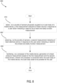
- FIG. 8 is a flow diagram 800 of an exemplary method of obtaining at least one bodily function measurement.
- a first measurement indicative of blood volume is obtained in response to a user action.
- the first measurement may be obtained via a plurality of sensors physically coupled to an outer body of a mobile device.
- the first measurement may be a photoplethysmography (PPG) measurement.
- PPG photoplethysmography
- the plurality of sensors may include at least one light sensor.
- the mobile device may also include at least one light source.
- Obtaining the first measurement may include measuring, via the at least one light sensor, reflected light from the light source reflected off of blood vessels within a user of the mobile device.
- the wearable watch obtains a PPG measurement of the user via the light sensors and light source within the wearable watch.
- the PPG measurement may be obtained by the PPG measurement module described in FIG. 1 .
- a second measurement indicative of heart electrical activity is obtained in response to the user action.
- the second measurement may be obtained via the plurality of sensors.
- the second measurement may be an electrocardiography (ECG) measurement.
- the plurality of sensors may include at least a first electrode and a second electrode.
- Obtaining the second measurement may include detecting completion of a circuit between the first electrode and the second electrode via a portion of the user's body.
- the wearable watch obtains an ECG measurement of the user via the electrodes located on the outer body of the wearable watch.
- the ECG measurement may be obtained by the ECG measurement module described in FIG. 1 .
- a blood pressure measurement based on the first measurement and the second measurement is facilitated via a processor of the mobile device.
- the processor may be contained within the outer body of the mobile device and the outer body may be sized to be portable for the user.
- the mobile device may be configured to perform a primary function and a secondary function. Facilitating the generation of the blood pressure measurement may be performed as the secondary function of the mobile device.
- the wearable watch may facilitate measurement of the user's blood pressure based on the obtained PPG and ECG measurements.
- the blood pressure may be determined by the blood pressure measurement module described in FIG. 1 .
- the mobile device is a watch.
- the mobile device is a wearable watch.
- the mobile device is a smartphone device.
- the mobile device is a smartphone device.
- At least one of the sensors is built into a multifunction surface, wherein the multifunction surface is configured to simultaneously obtain the first measurement or the second measurement and a user input.
- the smartphone device also capable of obtaining PPG and ECG measurements similar to the wearable watch
- the smartphone device includes a multifunction touchscreen surface that facilitates user input to the smartphone device.
- block 810 and block 820 may be performed by a first device and block 830 may be performed by a second device. That is, the measures of blood volume and heart electrical activity may be performed by a device separate than the generation of the blood pressure measurement.
- the measure of blood volume and heart electrical activity may be performed via a communication device worn by the user, whereas the generation of the blood pressure measurement may be performed by a server computer that receives the measures of blood volume and heart electrical activity from the communication device.
- the server computer could reside within a cloud system.
- FIG. 9 is another flow diagram 900 of an exemplary method of obtaining at least one bodily function measurement.
- a measurement to provide at least one measure of impedance associated with a user's body is obtained in response to a user action.
- the measurement may be obtained via a plurality of sensors comprising electrodes that are physically coupled to an outer body of the mobile device.
- a portion of the user's body positioned between the electrodes completes a circuit.
- the wearable watch obtains an impedance measurement of the user via the electrodes located on the outer body of the wearable watch.
- the impedance measurement may be obtained by the impedance measurement module described in FIG. 1 .
- a hydration level measurement based on the measure of impedance is facilitated via a processor of the mobile device.
- the processor is contained within the outer body of the mobile device.
- the outer body is sized to be portable for the user.
- the mobile device is configured to perform a primary function and a secondary function.
- the processor is configured to facilitate generation of the hydration level measurement as the secondary function of the mobile device.
- the wearable watch may facilitate measurement of the user's hydration level based on the obtained impedance measurement.
- the hydration level may be determined by the hydration level measurement module described in FIG. 1 .
- the multifunction surface is configured to simultaneously obtain the impedance measurement and a user input.
- the multifunction surface comprises Indium Tin Oxide (ITO).
- the multifunction surface comprises silver metal.
- the multifunction surface comprises a network of wires or a transparent conductor.
- the smartphone device also capable of obtaining impedance measurements similar to the wearable watch
- the mobile device is a watch.
- the mobile device is a wearable watch.
- the mobile device is a smartphone device.
- the mobile device is a smartphone device.
- block 910 may be performed by a first device and block 920 may be performed by a second device. That is, the measure of impedance may be performed by a device separate from the generation of the hydration level measurement.
- the measure of impedance may be performed via a communication device worn by the user, whereas the generation of the hydration level may be performed by a server computer that receives the measure of impedance from the communication device.
- the server computer could reside within a cloud system.
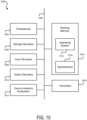
- FIG. 10 illustrates an example of a computing system in which one or more embodiments may be implemented.
- a computer system as illustrated in FIG. 10 may be incorporated as part of the above described computerized device.
- computer system 1000 can represent some of the components of a television, a computing device, a server, a desktop, a workstation, a control or interaction system in an automobile, a tablet, a netbook or any other suitable computing system.
- a computing device may be any computing device with an image capture device or input sensory unit and a user output device.
- An image capture device or input sensory unit may be a camera device.
- a user output device may be a display unit. Examples of a computing device include but are not limited to video game consoles, tablets, smart phones and any other hand-held devices.
- FIG. 10 illustrates an example of a computing system in which one or more embodiments may be implemented.
- FIG. 10 illustrates an example of a computing system in which one or more embodiments may be implemented.
- a computer system as illustrated in FIG. 10 may
- FIG. 10 provides a schematic illustration of one embodiment of a computer system 1000 that can perform the methods provided by various other embodiments, as described herein, and/or can function as the host computer system, a remote kiosk/terminal, a point-of-sale device, a telephonic or navigation or multimedia interface in an automobile, a computing device, a set-top box, a table computer and/or a computer system.
- FIG. 10 is meant only to provide a generalized illustration of various components, any or all of which may be utilized as appropriate.
- FIG. 10 therefore, broadly illustrates how individual system elements may be implemented in a relatively separated or relatively more integrated manner.
- elements of computer system 100 may be used to implement functionality of the mobile device 100 in FIG. 1 .
- the computer system 1000 is shown comprising hardware elements that can be electrically coupled via a bus 1002 (or may otherwise be in communication, as appropriate).
- the hardware elements may include one or more processors 1004, including without limitation one or more general-purpose processors and/or one or more special-purpose processors (such as digital signal processing chips, graphics acceleration processors, and/or the like); one or more input devices 1008, which can include without limitation one or more cameras, sensors, a mouse, a keyboard, a microphone configured to detect ultrasound or other sounds, and/or the like; and one or more output devices 1010, which can include without limitation a display unit such as the device used in embodiments of the invention, a printer and/or the like.
- processors 1004 including without limitation one or more general-purpose processors and/or one or more special-purpose processors (such as digital signal processing chips, graphics acceleration processors, and/or the like)
- input devices 1008 which can include without limitation one or more cameras, sensors, a mouse, a keyboard, a microphone configured to detect ultrasound or other sounds
- various input devices 1008 and output devices 1010 may be embedded into interfaces such as display devices, tables, floors, walls, and window screens. Furthermore, input devices 1008 and output devices 1010 coupled to the processors may form multi-dimensional tracking systems.
- the computer system 1000 may further include (and/or be in communication with) one or more non-transitory storage devices 1006, which can comprise, without limitation, local and/or network accessible storage, and/or can include, without limitation, a disk drive, a drive array, an optical storage device, a solid-state storage device such as a random access memory (“RAM”) and/or a read-only memory (“ROM”), which can be programmable, flash-updateable and/or the like.
- RAM random access memory
- ROM read-only memory
- Such storage devices may be configured to implement any appropriate data storage, including without limitation, various file systems, database structures, and/or the like.
- the computer system 1000 might also include a communications subsystem 1012, which can include without limitation a modem, a network card (wireless or wired), an infrared communication device, a wireless communication device and/or chipset (such as a Bluetooth TM device, an 802.11 device, a Wi-Fi device, a WiMax device, cellular communication facilities, etc.), and/or the like.
- the communications subsystem 1012 may permit data to be exchanged with a network, other computer systems, and/or any other devices described herein.
- the computer system 1000 will further comprise a non-transitory working memory 1018, which can include a RAM or ROM device, as described above.
- the computer system 1000 also can comprise software elements, shown as being currently located within the working memory 1018, including an operating system 1014, device drivers, executable libraries, and/or other code, such as one or more application programs 1016, which may comprise computer programs provided by various embodiments, and/or may be designed to implement methods, and/or configure systems, provided by other embodiments, as described herein.
- application programs 1016 may comprise computer programs provided by various embodiments, and/or may be designed to implement methods, and/or configure systems, provided by other embodiments, as described herein.
- code and/or instructions can be used to configure and/or adapt a general purpose computer (or other device) to perform one or more operations in accordance with the described methods.
- a set of these instructions and/or code might be stored on a computer-readable storage medium, such as the storage device(s) 1006 described above.
- the storage medium might be incorporated within a computer system, such as computer system 1000.
- the storage medium might be separate from a computer system (e.g., a removable medium, such as a compact disc), and/or provided in an installation package, such that the storage medium can be used to program, configure and/or adapt a general purpose computer with the instructions/code stored thereon.
- These instructions might take the form of executable code, which is executable by the computer system 1000 and/or might take the form of source and/or installable code, which, upon compilation and/or installation on the computer system 1000 (e.g., using any of a variety of generally available compilers, installation programs, compression/decompression utilities, etc.) then takes the form of executable code.
- Substantial variations may be made in accordance with specific requirements. For example, customized hardware might also be used, and/or particular elements might be implemented in hardware, software (including portable software, such as applets, etc.), or both. Further, connection to other computing devices such as network input/output devices may be employed. In some embodiments, one or more elements of the computer system 1000 may be omitted or may be implemented separate from the illustrated system. For example, the processor 1004 and/or other elements may be implemented separate from the input device 1008. In one embodiment, the processor is configured to receive images from one or more cameras that are separately implemented. In some embodiments, elements in addition to those illustrated in FIG. 10 may be included in the computer system 1000.
- Some embodiments may employ a computer system (such as the computer system 1000) to perform methods in accordance with the disclosure. For example, some or all of the procedures of the described methods may be performed by the computer system 1000 in response to processor 1004 executing one or more sequences of one or more instructions (which might be incorporated into the operating system 1014 and/or other code, such as an application program 1016) contained in the working memory 1018. Such instructions may be read into the working memory 1018 from another computer-readable medium, such as one or more of the storage device(s) 1006. Merely by way of example, execution of the sequences of instructions contained in the working memory 1018 might cause the processor(s) 1004 to perform one or more procedures of the methods described herein.
- a computer system such as the computer system 1000
- machine-readable medium and “computer-readable medium,” as used herein, refer to any medium that participates in providing data that causes a machine to operate in a specific fashion.
- various computer-readable media might be involved in providing instructions/code to processor(s) 1004 for execution and/or might be used to store and/or carry such instructions/code (e.g., as signals).
- a computer-readable medium is a physical and/or tangible storage medium.
- Such a medium may take many forms, including but not limited to, non-volatile media, volatile media, and transmission media.
- Non-volatile media include, for example, optical and/or magnetic disks, such as the storage device(s) 1006.
- Volatile media include, without limitation, dynamic memory, such as the working memory 1018.
- Transmission media include, without limitation, coaxial cables. copper wire and fiber optics, including the wires that comprise the bus 1002, as well as the various components of the communications subsystem 1012 (and/or the media by which the communications subsystem 1012 provides communication with other devices).
- transmission media can also take the form of waves (including without limitation radio. acoustic and/or light waves, such as those generated during radio-wave and infrared data communications).
- Common forms of physical and/or tangible computer-readable media include, for example, a floppy disk, a flexible disk, hard disk, magnetic tape, or any other magnetic medium, a CD-ROM, any other optical medium, punchcards, papertape, any other physical medium with patterns of holes, a RAM, a PROM, EPROM, a FLASH-EPROM, any other memory chip or cartridge, a carrier wave as described hereinafter, or any other medium from which a computer can read instructions and/or code.
- Various forms of computer-readable media may be involved in carrying one or more sequences of one or more instructions to the processor(s) 1004 for execution.
- the instructions may initially be carried on a magnetic disk and/or optical disc of a remote computer.
- a remote computer might load the instructions into its dynamic memory and send the instructions as signals over a transmission medium to be received and/or executed by the computer system 1000.
- These signals which might be in the form of electromagnetic signals, acoustic signals, optical signals and/or the like, are all examples of carrier waves on which instructions can be encoded, in accordance with various embodiments of the invention.
- the communications subsystem 1012 (and/or components thereof) generally will receive the signals, and the bus 1002 then might carry the signals (and/or the data, instructions, etc. carried by the signals) to the working memory 1018, from which the processor(s) 1004 retrieves and executes the instructions.
- the instructions received by the working memory 1018 may optionally be stored on a non-transitory storage device 1006 either before or after execution by the processor(s) 1004.
- configurations may be described as a process which is depicted as a flow diagram or block diagram. Although each may describe the operations as a sequential process, many of the operations can be performed in parallel or concurrently. In addition, the order of the operations may be rearranged. A process may have additional steps not included in the figure.
- examples of the methods may be implemented by hardware, software, firmware, middleware, microcode, hardware description languages, or any combination thereof. When implemented in software, firmware, middleware, or microcode, the program code or code segments to perform the necessary tasks may be stored in a non-transitory computer-readable medium such as a storage medium. Processors may perform the described tasks.
Landscapes
- Health & Medical Sciences (AREA)
- Life Sciences & Earth Sciences (AREA)
- Engineering & Computer Science (AREA)
- Biomedical Technology (AREA)
- Physics & Mathematics (AREA)
- Veterinary Medicine (AREA)
- Public Health (AREA)
- General Health & Medical Sciences (AREA)
- Animal Behavior & Ethology (AREA)
- Heart & Thoracic Surgery (AREA)
- Medical Informatics (AREA)
- Molecular Biology (AREA)
- Surgery (AREA)
- Pathology (AREA)
- Biophysics (AREA)
- Cardiology (AREA)
- Physiology (AREA)
- Hematology (AREA)
- Psychiatry (AREA)
- Nuclear Medicine, Radiotherapy & Molecular Imaging (AREA)
- Radiology & Medical Imaging (AREA)
- Multimedia (AREA)
- Vascular Medicine (AREA)
- Psychology (AREA)
- Anesthesiology (AREA)
- Signal Processing (AREA)
- Computer Vision & Pattern Recognition (AREA)
- Artificial Intelligence (AREA)
- Child & Adolescent Psychology (AREA)
- Developmental Disabilities (AREA)
- Educational Technology (AREA)
- Acoustics & Sound (AREA)
- Pain & Pain Management (AREA)
- Social Psychology (AREA)
- Hospice & Palliative Care (AREA)
- Measuring Pulse, Heart Rate, Blood Pressure Or Blood Flow (AREA)
- Measurement And Recording Of Electrical Phenomena And Electrical Characteristics Of The Living Body (AREA)
- Measurement Of The Respiration, Hearing Ability, Form, And Blood Characteristics Of Living Organisms (AREA)
- Measuring And Recording Apparatus For Diagnosis (AREA)
- Telephone Function (AREA)
Description
- Aspects of the disclosure relate to mobile devices, and more particularly, a system and method for obtaining at least one bodily function measurement of a user operating a mobile device.
- It is often desirable for a user to be aware his/her bodily function measurements, which may provide physiological measures of stress, measures of hydration, and other measures of general health. Physiological measures of stress may be used to communicate to a user instructions to alter his/her behavior, e.g., taking a break, taking deep breaths, etc. Measures of hydration may be used by athletes or generally active individuals to ensure that they stay hydrated to maintain physical performance. Additionally, this information may be useful for individuals who work in hot or dry environments and must maintain proper hydration. Further, this information may be useful for elderly individuals whose sense of hydration is decreased and are more prone to becoming dehydrated. Thus, important bodily function measurements may include measurements of a user's blood pressure and/or hydration state.
- A user's blood pressure may be measured using a pulse-measuring device. Typical pulse-measuring devices use either photoplethysmography (PPG) or electrocardiography (ECG) to measure a user's pulse. A user's systolic blood pressure or diastolic blood pressure may be determined using a combination of the PPG and ECG using a technique known as pulse transit time (PTT). The systolic blood pressure, along with other inputs such as pulse rate variability (PRV) and galvanic skin response (GSR) may be useful in determining the user's physiological measures of stress. However, existing mobile device solutions for obtaining PPG measurements and ECG measurements can only obtain measurements for one or the other. That is, existing mobile device solutions can only obtain a PPG measurement or an ECG measurement, but not both.
- A user's hydration state may be determined by measuring a total body water amount using a bioelectric impedance analysis (BIA). BIA measurements are typically accurate and may fall within 200ml of the actual value when performed properly. Typically, existing solutions to measure BIA require professional equipment in a clinical setting. Additionally, the few devices that exist to measure BIA outside of a clinical setting are not very mobile, e.g., they may not fit within a user's pocket or be integrated into another device that the user typically always has with them.
- Accordingly, a need exists for a mobile solution to obtain both PPG and ECG measurements used for determining a user's blood pressure and to obtain a body water content measurement used for determining a user's hydration state.
Attention is drawn toEP 2 644 089 A1
Further attention is drawn toEP 1 977 688 A2
Attention is also drawn toUS 2010 160 793 A1 (D3) describing a biosignal measurement module that includes a biosignal measurement unit for measuring an electrocardiogram signal and a pulse signal of a subject, a pose detection unit for detecting a position of the biosignal measurement module and outputting position signals, and a .processing unit for receiving the electrocardiogram signal, the pulse signal, and the position signals. The processing unit generates a height variation parameter, which indicates the height difference between the position of the biosignal measurement module and a reference position, according to the position signals. Furthermore, it calculates a current pulse transit time according to the electrocardiogram signal and the pulse signal and compensates for the current pulse transit time according to the height variation parameter to obtain a compensated pulse transit time. The processing unit obtains a blood pressure signal according to the compensated pulse transit time. - In accordance with the present invention a mobile device, and a method, as set forth in the independent claims, respectively, are provided. Preferred embodiments of the invention are described in the dependent claims.
- Certain embodiments are described that for obtaining at least one bodily function measurement of a user operating a mobile device.
- In some embodiments, a mobile device for obtaining at least one bodily function measurement comprises an outer body sized to be portable for a user, a processor contained within the outer body, and a plurality of sensors physically coupled to the outer body for obtaining data accessible by the processor. One or more sensors of the sensors is configured to obtain a first measurement indicative of blood volume in response to a user action, wherein at least one of the sensors configured to obtain the first measurement is contained within a contact button coupled to the outer body. One or more of the sensors is configured to obtain a second measurement indicative of heart electrical activity in response to the user action. The processor is configured to facilitate generation of a blood pressure measurement based on the first measurement and the second measurement.
- In some embodiments, the mobile device is configured to perform a primary function and a secondary function, and wherein the processor is configured to facilitate generation of the blood pressure measurement as the secondary function of the mobile device.
- In some embodiments, the first measurement indicative of blood volume comprises a photoplethysmography (PPG) measurement.
- In some embodiments, the second measurement indicative of heart electrical activity comprises an electrocardiography (ECG) measurement.
- In some embodiments, the one or more of the sensors is configured to obtain the first measurement comprises at least one light sensor, and wherein the mobile device further comprises at least one light source and the at least one light sensor measures reflected light from the light source reflected off of blood vessels within a user of the mobile device to obtain the first measurement.
- In some embodiments, the at least one light sensor includes an infrared (IR) light emitting diode (LED).
- In some embodiments, the one or more of the sensors is configured to obtain the second measurement indicative of heart electrical activity comprises at least a first electrode and a second electrode, and wherein a portion of a user of the mobile device's body completes a circuit between the first electrode and the second electrode.
- In some embodiments, the mobile device is a watch.
- In some embodiments, the mobile device is a smartphone device.
- In some embodiments, method for obtaining at least one bodily function measurement via a mobile device comprises obtaining, via a plurality of sensors physically coupled to an outer body of the mobile device, a first measurement indicative of blood volume in response to a user action, wherein at least one of the sensors is contained within a contact button coupled to the outer body. The method further comprises obtaining, via the plurality of sensors, a second measurement indicative of heart electrical activity in response to the user action. The method also comprises facilitating, via a processor of the mobile device, generation of a blood pressure measurement based on the first measurement and the second measurement, wherein the processor is contained within the outer body of the mobile device, the outer body sized to be portable for the user.
- In some embodiments, an apparatus for obtaining at least one bodily function measurement comprises means for obtaining, via a plurality of sensors physically coupled to an outer body of a mobile device, a first measurement indicative of blood volume in response to a user action, wherein at least one of the sensors is contained within a contact button coupled to the outer body. The method further comprises means for obtaining, via the plurality of sensors, a second measurement indicative of heart electrical activity in response to the user action. The method also comprises means for facilitating, via a processor of the mobile device, generation of a blood pressure measurement based on the first measurement and the second measurement, wherein the processor is contained within the outer body of the mobile device, the outer body sized to be portable for the user.
- In some embodiments, one or more non-transitory computer-readable media storing computer-executable instructions for obtaining at least one bodily function measurement that, when executed, cause one or more computing devices included in a mobile device to obtain, via a plurality of sensors physically coupled to an outer body of the mobile device, a first measurement indicative of blood volume in response to a user action, wherein at least one of the sensors is contained within a contact button coupled to the outer body. The computer-executable instructions, when executed, further cause the one or more computing devices included in a device to obtain, via the plurality of sensors, a second measurement indicative of heart electrical activity in response to the user action. The computer-executable instructions, when executed, further cause the one or more computing devices included in a device to facilitate, via a processor of the mobile device, generation of a blood pressure measurement based on the first measurement and the second measurement, wherein the processor is contained within the outer body of the mobile device, the outer body sized to be portable for the user.
- In some embodiments, a mobile device for obtaining at least one bodily function measurement comprises an outer body sized to be portable for a user, a processor contained within the outer body. and a plurality of sensors physically coupled to the outer body for obtaining data accessible by the processor. The plurality of sensors comprises electrodes and a portion of a user's body positioned between the electrodes completes a circuit and a measurement to provide at least one measure of impedance associated with the user's body in response to a user action. The processor is configured to facilitate generation of a hydration level measurement based on the measure of impedance.
- In some embodiments, the mobile device is configured to perform a primary function and a secondary function, and wherein the processor is configured to facilitate generation of the hydration level measurement as the secondary function of the mobile device.
- In some embodiments, at least one of the sensors is built into a multifunction surface, wherein the multifunction surface is configured to simultaneously obtain the impedance measurement and a user input.
- In some embodiments, the multifunction surface comprises silver metal.
- In some embodiments, the multifunction surface comprises Indium Tin Oxide (ITO).
- In some embodiments, the mobile device is a watch.
- In some embodiments, the mobile device is a smartphone device.
- In some embodiments, a method for obtaining at least one bodily function measurement via a mobile device comprises obtaining, via a plurality of sensors comprising electrodes and physically coupled to an outer body of the mobile device, a measurement to provide at least one measure of impedance associated with a user's body in response to a user action, wherein a portion of the user's body positioned between the electrodes completes a circuit. The method also comprises facilitating, via a processor of the mobile device, generation of a hydration level measurement based on the measure of impedance, wherein the processor is contained within the outer body of the mobile device, the outer body sized to be portable for the user.
- In some embodiments, an apparatus for obtaining at least one bodily function measurement via a mobile device comprises means for obtaining, via a plurality of sensors comprising electrodes and physically coupled to an outer body of the mobile device, a measurement to provide at least one measure of impedance associated with a user's body in response to a user action, wherein a portion of the user's body positioned between the electrodes completes a circuit. The apparatus further comprises means for facilitating, via a processor of the mobile device, generation of a hydration level measurement based on the measure of impedance, wherein the processor is contained within the outer body of the mobile device, the outer body sized to be portable for the user.
- In some embodiments, one or more non-transitory computer-readable media storing computer-executable instructions for obtaining at least one bodily function measurement that, when executed, cause one or more computing devices included in a mobile device to obtain, via a plurality of sensors comprising electrodes and physically coupled to an outer body of the mobile device, a measurement to provide at least one measure of impedance associated with a user's body in response to a user action, wherein a portion of the user's body positioned between the electrodes completes a circuit. The computer-executable instructions, when executed, further cause the one or more computing devices included in a device to facilitate, via a processor of the mobile device, generation of a hydration level measurement based on the measure of impedance, wherein the processor is contained within the outer body of the mobile device, the outer body sized to be portable for the user.
- Aspects of the disclosure are illustrated by way of example. In the accompanying figures, like reference numbers indicate similar elements, and:
-
FIG. 1 illustrates a mobile device configured to obtain PPG and ECG measurements of a user, according to some embodiments; -
FIG. 2 illustrates a smartphone device configured to obtain PPG and ECG measurements of a user, according to some embodiments; -
FIG. 3 illustrates a wristwatch device configured to obtain PPG, ECG, and impedance measurements of a user, according to some embodiments; -
FIG. 4A illustrates a cross sectional view of the wristwatch device ofFIG. 3 and graphs showing measurements obtained by the wristwatch device, according to some embodiments; -
FIG. 4B illustrates a cross sectional view of the wristwatch device ofFIG 3 . where the sensor for obtaining the PPG measurement is contained within a contact button of the wristwatch device, according to some embodiments; -
FIG. 4C illustrates a top view of the wristwatch device ofFIG. 3 where the sensor for obtaining the PPG measurement is contained within a contact button of the wristwatch device, according to some embodiments; -
FIG. 4D illustrates a graph comparing heart activity measurements between contact button contained PPG sensor and a wrist based PPG sensor, according to some embodiments; -
FIG. 5 a schematic diagram illustrating a method of obtaining impedance measurements of a user, according to some embodiments; -
FIG. 6 is a schematic diagram of two resistors and a capacitor representing conduction through tissue, according to some embodiments; -
FIG. 7 is a flow diagram illustrating a plurality of derived metrics from a plurality of sensor metrics, according to some embodiments; -
FIG. 8 is a flow diagram of an exemplary method of obtaining at least one bodily function measurement; -
FIG. 9 is another flow diagram of an exemplary method of obtaining at least one bodily function measurement; and -
FIG. 10 illustrates an example of a computing system in which one or more embodiments may be implemented. - Several illustrative embodiments will now be described with respect to the accompanying drawings, which form a part hereof. While particular embodiments, in which one or more aspects of the disclosure may be implemented, are described below, other embodiments may be used and various modifications may be made without departing from the scope of the disclosure or the spirit of the appended claims.
-
FIG. 1 illustrates a simplified block diagram of amobile device 100 that may incorporate one or more embodiments.Mobile device 100 includes aprocessor 110,microphone 120,display 130,input device 140,speaker 150,memory 160,camera 170,sensors 180,light source 185, and computer-readable medium 190. -
Processor 110 may be any general-purpose processor operable to carry out instructions on themobile device 100. Theprocessor 110 is coupled to other units of themobile device 100 includingmicrophone 120,display 130,input device 140,speaker 150,memory 160,camera 170,sensors 180,light source 185, and computer-readable medium 190. -
Microphone 120 may be any an acoustic-to-electric transducer or sensor that converts sound into an electrical signal. Themicrophone 120 may provide functionality for a user of themobile device 100 to record audio or issue voice commands for themobile device 100. -
Display 130 may be any device that displays information to a user. Examples may include an LCD screen, CRT monitor, or seven-segment display. -
Input device 140 may be any device that accepts input from a user. Examples may include a keyboard, keypad, or mouse. In some embodiments, themicrophone 120 may also function as aninput device 140. -
Speaker 150 may be any device that outputs sound to a user. Examples may include a built-in speaker or any other device that produces sound in response to an electrical audio signal and/or ultrasonic signal(s). -
Memory 160 may be any magnetic, electronic, or optical memory.Memory 160 includes two memory modules,module 1 162 andmodule 2 164. It can be appreciated thatmemory 160 may include any number of memory modules. An example ofmemory 160 may be dynamic random access memory (DRAM). -
Camera 170 is configured to capture one or more images via a lens located on the body ofmobile device 100. The captured images may be still images or video images. Thecamera 170 may include a CMOS image sensor to capture the images. Various applications running onprocessor 110 may have access tocamera 170 to capture images. It can be appreciated thatcamera 170 can continuously capture images without the images actually being stored within themobile device 100. Captured images may also be referred to as image frames. -
Sensors 180 is a plurality of sensors configured to obtain data accessible by the processor. Thesensors 180 is also physically coupled to the outer body of themobile device 100. The plurality ofsensors 180 may include one or morelight sensors 182 and/or one ormore electrodes 184. Thelight sensors 182 may be configured to facilitate measurement of reflected light from the light source 185 (described below) reflected off of blood vessels within a user of themobile device 100 to obtain the a PPG measurement indicative of the user's blood volume. A portion of a user of the mobile device's 100 body may complete a circuit between a first electrode and a second electrode, e.g., when the user touches bothelectrodes 184. Theelectrodes 184 may be configured to facilitate measurement of heart electrical activity of the user to obtain an ECG measurement. Theelectrodes 184 may also be configured to facilitate measurement of impedance of the user of themobile device 100 to obtain a level measurement. -
Light source 185 may be any source of light configured to emit light through a user's body. In some embodiments, thelight source 185 may be a LED light source. The emitted light may be of a wavelength that can pass through parts of a user's body. For example, thelight source 185 may emit LED light through a user's wrist. In some embodiments, themobile device 100 may include multiplelight sources 185. The light emitted fromlight source 185 may reflect off of blood vessels within the user's body and the reflected light may be measured by one or morelight sensors 182 to obtain a PPG measurement, as described above. It can be appreciated that emitted light may be of different wavelengths depending on different wavelengths. For example, different wavelengths of light may be appropriate to improve the signal, reduce noise, deal with dark skin colors, measure the blood's oxygen content, or penetrate to different depths of the user's body. - Computer-
readable medium 190 may be any magnetic, electronic, optical, or other computer-readable storage medium. Computer-readable storage medium 190 includesPPG measurement module 192,ECG measurement module 194, bloodpressure measurement module 196,impedance measurement module 198, and hydrationlevel measurement module 199. -
PPG measurement module 192 is configured to, when executed byprocessor 110, obtain a photoplethysmography (PPG) measurement. The PPG measurement may be a measurement of blood volume of a user operating themobile device 100. The PPG measurement may be obtained by thePPG measurement module 192 in response to a user action. ThePPG measurement module 192 may interface with thelight source 185 andlight sensors 182 in order to obtain the PPG measurement. Upon indication by the user of a need for a PPG measurement, thePPG measurement module 192 may direct thelight source 185, or multiple light sources, to emit light through the user's body. As described above. the emitted light may reflect off or transmitted through blood vessels within the user's body and may be detected by one or morelight sensors 182 within themobile device 100. ThePPG measurement module 192 may measure, by interfacing with the one or more light sensors, the amount of reflected or transmitted light detected by the one or morelight sensors 182. ThePPG measurement module 192 may then determine a PPG measurement that is indicative of the user's blood volume based on the measurement of the reflected light. -
ECG measurement module 194 is configured to, when executed byprocessor 110, obtain an electrocardiography (ECG) measurement. The ECG measurement may be a measurement of heart electrical activity of a user operating themobile device 100. The ECG measurement may be obtained by theECG measurement module 194 in response to a user action. TheECG measurement module 194 may interface with theelectrodes 184 in order to obtain the ECG measurement. Upon indication by the user of a need for an ECG measurement, theECG measurement module 194 may interface with theelectrodes 184 to measure (assuming the user's body completes a circuit between the electrodes 184) electrical impulse(s) generated by the polarization and depolarization of cardiac tissue within the user's body. In some embodiments, the electrical impulse(s) may be generated by the beating of the user's heart. In some embodiments, theECG measurement module 194 may interface with theelectrodes 184 to measure the electrical impulse(s) automatically upon the user's body completing a circuit between theelectrodes 184. TheECG measurement module 194 may then determine an ECG measurement based on the measured electrical impulse(s). It can be appreciated that ECG measurement can be obtained using two or more electrode leads. - Blood
pressure measurement module 196 is configured to, when executed byprocessor 110, generate a blood pressure measurement of the user based on the PPG measurement and the ECG measurement. According to Poon, C.C.Y.; Zhang, Y.T. "Cuff-less and Noninvasive Measurements of Arterial Blood Pressure by Pulse Transit Time", Engineering in Medicine and Biology 27th Annual Conference. 2005. IEEE, On page(s): 1 - 4, the calculation of the blood pressure measurement based on the PPG measurement and the ECG measurement is well known in the art. -
Impedance measurement module 198 is configured to, when executed byprocessor 110, obtain an impedance measurement. The impedance measurement may be indicative of a hydration level of a user operating themobile device 100. The impedance measurement may be obtained by theimpedance measurement module 198 in response to a user action. Inimpedance measurement module 198 may interface with theelectrodes 184 in order to obtain the impedance measurement. Upon indication by the user of a need for an impedance measurement, theimpedance measurement module 198 may interface with theelectrodes 184 to measure (assuming the user's body completes a circuit between the electrodes 184) electrical impedance through the user's body. In some embodiments, theimpedance measurement module 198 may interface with theelectrodes 184 to measure the electrical impedance automatically upon the user's body completing a circuit between theelectrodes 184. - Hydration
level measurement module 199 is configured to, when executed byprocessor 110, obtain a hydration level measurement based on the impedance measurement obtained by theimpedance measurement module 198. The hydrationlevel measurement module 199 may determine the hydration level from the measured impedance using techniques well known in the art. - It can be appreciated that the outer body of the
mobile device 100 may be sized to be portable for a user. It can be appreciated that the term "portable" may refer to something that is able to be easily carried or moved, and may be a light and/or small. In the context of embodiments of the present invention, the term portable may refer to something easily transportable by the user or wearable by the user. For example, themobile device 100 may be a smartphone device or a watch wearable by the user. Other examples of portable devices include a head-mounted display, calculator, portable media player, digital camera, pager, personal navigation device, etc. Examples of devices that may not be considered portable include a desktop computer, traditional telephone, television, appliances, etc. It can be appreciated that the bodily function measurements can be obtained via the smartphone, watch, or any other of the mentioned devices. -
FIG. 2 illustrates asmartphone device 210 configured to obtain PPG and ECG measurements of a user, according to some embodiments. It can be appreciated that thesmartphone device 210 is only one example of amobile device 100. Thesmartphone device 210 may include a plurality ofcontacts 220. In some embodiments, asingle contact 220 may be positioned at each end of thesmartphone device 210. In other embodiments, a devicefront surface 250 of thesmartphone device 210 may include a contact layer including, e.g., silver metal or Indium Tin Oxide (ITO). Thesmartphone device 210 may obtain both PPG and ECG measurements of theuser 260. In some embodiments, thedevice front surface 250 may be a touchscreen. - For example, the
user 260 may hold thesmartphone device 210 with his/herfirst hand 240 touching one or more of thecontacts 220 and with his/hersecond hand 230 touching thedevice front surface 250. Upon theuser 260 performing this action, thecontacts 220 and the contact layer of thedevice front surface 250 may complete a circuit through the user's 260 body. Thesmartphone device 210 may then measure an electrical potential through the completed circuit to determine the ECG measurement. It can be appreciated that the ECG measurement may also be obtained without the user'sfirst hand 240 orsecond hand 230 contacting thedevice front surface 250. That is, the user'sfirst hand 240 may make contact with afirst side contact 220 and the user'ssecond hand 230 may make contact with asecond side contact 220 to complete the circuit. Alternatively, theuser 260 may make contact with bothside contacts 220 using only his/herfirst hand 240 or second hand 230 (see below for a measurement of PPG or Galvanic Skin Response (GSR)). Alternatively, and not illustrated inFIG. 1 , sensors positioned and/or touched at other locations, for example legs, feet, ankles, knees, elbows, arms, neck, head, etc. could also be used to generate PPG, GSR and possibly ECG, depending on the location and how the contact was made. - The device
front surface 250 of thesmartphone device 210 may also obtain a PPG measurement of theuser 260 by using an optical based technology. For example, when theuser 260 touches thedevice front surface 250, alight source 185 may shine a light into the user's 260 skin, one or more sensors may measure the blood flow through the capillaries and thus determine a heart rate (PPG) of the user. This process is described in further detail below. In some embodiments, the light source may be a dedicated light source that is part of thesmartphone device 210. - Accordingly, by obtaining both the PPG and ECG measurements of the
user 260, a PTT technique may be used to determine the user's blood pressure. Thesmartphone device 210 may then provide important information to theuser 260, based on the determined blood pressure (described further below). - Additionally, the
smartphone device 210 may obtain an impedance measurement of the user using BIA techniques. In some embodiments, the impedance measurement may be obtained via the contact layer of thedevice front surface 250. The process of obtaining the impedance measurement is described in further detail below. - It can be appreciated that the
device front surface 250 serves multiple functions. That is, thedevice front surface 250 is used to obtain ECG, PPG, and/or impedance measurements as described above, and is also used as a user input device. Theuser 260 may use thedevice front surface 250 to provide input to applications being executed on thesmartphone device 210. When theuser 260 wishes to obtain a bodily function measurement using thedevice front surface 250, theuser 260 may place thesmartphone device 210 into a measurement mode. Alternatively, thesmartphone device 210 may automatically detect the user's intention to obtain a bodily function measurement, e.g., from theuser 260 placing his/her finger in a particular location on thedevice front surface 250 or touching thedevice front surface 250 for a predetermined period of time. Alternatively, thesmartphone device 210 may regularly scan and store vital signs of theuser 260 in the user's normal course of operating thedevice 210, without the user wanting or needed a particular vital sign report at that time. -
FIG. 3 illustrates awristwatch device 310 configured to obtain PPG, ECG, and impedance measurements of a user, according to some embodiments. Thewristwatch device 310 illustrated inFIG. 3 operates similarly to thesmartphone device 210 inFIG. 2 . That is, thewristwatch device 310 may obtain PPG, ECG, and impedance measurements of theuser 260 via a plurality of contacts. In some embodiments, one or more contacts may be placed at the bottom of thewristwatch device 310, where the contact makes a continuous contact with the user's 260 wrist while theuser 260 wears thewristwatch device 310. - The
wristwatch device 310 also includes amultifunction button 320, which is used to obtain a bodily function measurement and also as a user input device. For example, themultifunction button 320 may be used by theuser 260 to set a date and/or time for thewristwatch device 310. The multifunction button may have an integrated electrode on the surface. Theuser 260 may also use themultifunction button 320 to obtain an ECG measurement by touching thebutton 320 to complete a circuit (via the other contacts) through the user's body. In some embodiments, themultifunction button 320 may be integrated into a touchscreen of thewristwatch device 310. - The PPG and hydration measurements may be obtained in a similar fashion as described with respect to the smartphone device of
FIG. 2 , e.g., via the contacts on thewristwatch device 310. The PPG measurement may also be obtained using optical techniques, as described below. - The
wristwatch device 310 may be designed to be portable such that the user may easily wear the device or carry it on his/her person. In some embodiments, thewristwatch device 310 may perform everyday functions other than obtaining PPG, ECG, and impedance measurements of the user. For example, thewristwatch device 310 may provide the current time, a stopwatch function, a calendar function, communication functions, etc. The PPG, ECG, and impedance measurements functions may be available in addition to the other described functions on thewristwatch device 310. -
FIG. 4A illustrates a crosssectional view 410 of thewristwatch device 310 ofFIG. 3 andgraphs sectional view 410 of thewristwatch device 310 shows aphotodetector 412, a plurality of light emitting diodes (LED) 414, and a plurality ofelectrodes contacts 416. Additionally, the crosssectional view 410 also illustrates parts of a user's wrist, e.g.,radial bone 418 andulnar bone 419. In some embodiments, the plurality ofLEDs 414 can be infrared (IR) LEDs. The IR LEDs may provide advantages to the user, such as not distracting the user from normal operation of thewristwatch device 310 because the IR LEDs may not emit any visible light. - The
wristwatch device 310 may obtain PPG measurements of the user by using optical techniques. To obtain a PPG measurement, the LEDs 414 (typically positioned at the bottom of thewristwatch device 310 and on top of the user's wrist) may emit a light into the user's skin. The reflected light may be received at thephotodetector 412. The user's blood volume may be determined based off of the reflected light as compared against time. From this data, the user's PPG measurement may be determined. In some embodiments, the determination of the user's blood volume may be determined from a change in the user's blood volume. More specifically, a change in the diameter of the blood vessels that are being probed by theLEDs 414. - Additionally, the user's ECG measurement may be obtained using the plurality of
contacts 416 as described above with respect toFIG. 3 . It can be appreciated that in thewristwatch device 310 embodiment, the plurality ofcontacts 416 may continuously be in contact with the user's skin while the user is wearing thewristwatch device 310 around his/her wrist. The user may then touch, with his/her hand that is not wearing thewristwatch device 310, anothercontact 416 that is located at another location on thewristwatch device 310 to complete the circuit through the user's body. - Similarly, the user's hydration measurements may also be obtained by using the plurality of
contacts 416 and determining impedance through the user's body. -
Graph 420 illustrates the intensity of the obtained light reflections at thephotodetector 412 against time. In this example, the duration between each pulse is approximately one second. From this graph, the user's PPG can be determined. -
Graph 430 shows a user's heart rate variability by comparing the user's ECG and the user's PPG. As shown ingraph 440, the PTT can be determined by taking the difference between a peak of an ECG pulse and the corresponding inflection point (at the same time interval) of the PPG pulse. The PTT may then be used to determine the user's blood pressure, which is well known in the art. -
FIG. 4B illustrates a cross sectional view of thewristwatch device 310 ofFIG 3 . where the sensor for obtaining the PPG measurement is contained within a contact button of the wristwatch device, according to some embodiments. In contrast to the wristwatch device illustrated inFIG. 4A , thewristwatch device 310 illustrated inFIG. 4B contains aPPG sensor 470 within acontact button 460 on thewristwatch device 310. The user may place his/her finger on thecontact button 460 such that thePPG sensor 470 can obtain the PPG signal from the finger to determine the PPG measurement. In some embodiments, thePPG sensor 470 may be an optical sensor. - Certain advantages may be realized by placing the
PPG sensor 470 within thecontact button 460, including but not limited to, allowing for a faster and more accurate reading of the PPG signal from the user's finger as opposed to from the user's wrist. This can result in faster determination of the user's PTT. It can be appreciated that thePPG sensor 470 within thecontact button 460 can provide better results than measuring the PPG from the arm/wrist due to the vascularization of the arm associated with obtaining the PPG measurement from the arm. That is, the arteries near the surface of the arm where the measurement is attempting to be obtained from can blur out the signal due to the high number of routes that blood cloud flow. However, in the finger, typically an artery runs along the inside between the user's fingers to the tip of the finger before expanding out into many capillaries. As such, a clear signal can be obtained from the finger. - In some embodiments, the
contact button 460 may be a multi-function button operable to serve other functions of thewristwatch device 310. For example, the multi-function button can be used to interact with thewristwatch device 310 for setting the time, starting/stopping a stopwatch, or any other function typically available in awristwatch device 310. - In the implementation of
FIG. 4B , thewristwatch device 310 may also obtain an ECG measurement as described with respect toFIG. 4A , in accordance with some embodiments. That is, the ECG measurement can be obtained by theelectrical contact 416 in contact with the user's arm/wrist andcontact button 460 in contact with the user's finger, whereby the circuit is completed. Advantageously, when the user touches his/her finger to thecontact button 460, both the ECG measurement and the PPG measurement can be obtained. -
FIG. 4C illustrates a top view of the wristwatch device ofFIG. 3 where the sensor for obtaining the PPG measurement is contained within a contact button of the wristwatch device, according to some embodiments.FIG. 4C illustrates the top view of thewristwatch device 310 described inFIG. 4B . As illustrated in the figure, thePPG sensor 470 is contained within thecontact button 460. Theelectrical contact 416 used to obtain ECG measurement data can be located at the bottom of thewristwatch device 310. - In some embodiments, the
contact button 460 may have an opening such that light from thePPG sensor 470 can travel through the opening to obtain an optical PPG measurement. In some embodiments, thecontact button 460 may made of a material that optimizes metal electrodes, such as stainless steel. -
FIG. 4D illustrates a graph showing heart activity measurements obtained from PPG measurements obtained at the finger, according to some embodiments. The graph shows anelectrocardiogram signal 480 and aPPG signal 490 obtained at the finger of a 24-year old male. It can be appreciated that the PPG signal 490 does not contain much noise and the signal is smooth and/or rounded. Due to the better resolution of the PPG signal 490 provided by obtaining the measurement from the finger rather than the wrist, other information such as the heart activity can also benefit from the increased accuracy. Additional information that can be determined due to the better resolution of the PPG signal 490 can include, but is not limited to, systolic blood pressure and a measure of vascular stiffness. -
FIG. 5 is a schematic diagram 500 of a method for obtaining impedance measurements of a user, according to some embodiments. The mobile device may be either the smartphone device described inFIG. 2 , the wristwatch device described inFIG. 3 , or any other mobile device. As described above, the impedance measurement of the user may be used to determine the user's hydration level using BIA techniques. The user'sbody 510 essentially functions as a capacitance and resistance network in this illustration. When the user'sbody 510 makes contact with the contact points 530, animpedance converter 520 may determine the impedance value through the user'sbody 510. In this scenario, the user'sbody 510 may act as a capacitor. The impedance value may be a function of surface tissue impedance and deep tissue impedance. The impedance value may then be used to estimate a total body water content of the user'sbody 510. This figure shows measuring the impedance through one leg, the torso, and one arm. The method works the same way measuring through both arms and the chest. In some embodiments, the mobile device may include phase-sensitive electronics to distinguish between electrical resistance and reactance. - Upon determining the user's hydration level, the mobile device may provide a notification to the user. The types of notifications are described in further detail with respect to
FIG. 7 . -
FIG. 6 is a schematic diagram 600 of two resistors and a capacitor representing conduction through tissue, according to some embodiments. InFIG. 6 , xc represents the capacitance of the user's cell walls, R(ICW) represents the resistance of the body water inside of the user's cells, and R(ECW) represents the resistance of the body water outside of the user's cells. The circuit shown inFIG. 6 may be used as part of the schematic diagram inFIG. 5 to determine the hydration level of the user by determining an electrical impedance through the user's body. -
FIG. 7 is a flow diagram 700 illustrating a plurality of derivedmetrics 720 from a plurality ofsensor metrics 710, according to some embodiments. The plurality ofsensor metrics 710 may include, but is not limited to, PPG pulse measurement, accelerometer measurements, AC biometric impedance measurements, and 2-lead ECG heart rate measurements. Thesesensor metrics 710 may be obtained by taking measurements via the mobile device. Based on data from thesensor metrics 710, a plurality of derivedmetrics 720 may be derived. These derived metrics may include, but is not limited to, heart rate, heart rate variability, stress calculation, blood pressure, and hydration state. - For example, when a PPG pulse measurement is obtained, using the techniques described herein, the user's heart rate and/or heart rate variability may be determined. The PPG pulse measurement may be combined with an ECG heart rate measurement to determine the user's blood pressure using PTT techniques. Based on the determined blood pressure, a user's stress level may be determined. If it is determined that the user is at a high stress level, the mobile device may notify the user to take a deep breath, go for a walk, drink a glass of water, etc. As shown, the stress level may also be determined from the user's GSR data.
- In another example, when an AC bioelectric impedance measurement is obtained, using the techniques described herein, the user's hydration state may be determined from data regarding the total body water of the user. If the user's hydration state is determined to be low, the mobile device may notify the user to drink a glass of water. On the other hand, if the user's hydration state is determined to be adequate, the mobile device may notify the user that to keep up the good work.
- In another example, energy calculations may be determined based upon accelerometer and gyroscope data obtained by the mobile device. For example, if the user is moving around actively, the accelerometer data may indicate a high level of movement and the mobile device may determine that the user's energy level is high. The mobile device may notify the user to continue being active. In some embodiments, the mobile device may keep track of the user's energy level throughout the day and notify the user upon predetermined intervals to become active in order to reach a threshold amount of activity for the day.
- In some embodiments, accelerometer measurements may be used to determine the user's heart rate and/or heart rate variability. The same calculations described above may determined/calculated using these measurements.
- It is understood that the specific order or hierarchy of steps in the processes disclosed is an illustration of exemplary approaches. Based upon design preferences, it is understood that the specific order or hierarchy of steps in the processes may be rearranged. Further, some steps may be combined or omitted. The accompanying method claims present elements of the various steps in a sample order, and are not meant to be limited to the specific order or hierarchy presented.
- The previous description is provided to enable any person skilled in the art to practice the various aspects described herein. Various modifications to these aspects will be readily apparent to those skilled in the art, and the generic principles defined herein may be applied to other aspects. Moreover, nothing disclosed herein is intended to be dedicated to the public.
-
FIG. 8 is a flow diagram 800 of an exemplary method of obtaining at least one bodily function measurement. Inblock 810, a first measurement indicative of blood volume is obtained in response to a user action. The first measurement may be obtained via a plurality of sensors physically coupled to an outer body of a mobile device. In some embodiments, the first measurement may be a photoplethysmography (PPG) measurement. - In some embodiments, the plurality of sensors may include at least one light sensor. The mobile device may also include at least one light source. Obtaining the first measurement may include measuring, via the at least one light sensor, reflected light from the light source reflected off of blood vessels within a user of the mobile device. For example, in
FIG. 3 , the wearable watch obtains a PPG measurement of the user via the light sensors and light source within the wearable watch. The PPG measurement may be obtained by the PPG measurement module described inFIG. 1 . - In
block 820, a second measurement indicative of heart electrical activity is obtained in response to the user action. The second measurement may be obtained via the plurality of sensors. In some embodiments, the second measurement may be an electrocardiography (ECG) measurement. - In some embodiments, the plurality of sensors may include at least a first electrode and a second electrode. Obtaining the second measurement may include detecting completion of a circuit between the first electrode and the second electrode via a portion of the user's body. For example, in
FIG. 3 , the wearable watch obtains an ECG measurement of the user via the electrodes located on the outer body of the wearable watch. The ECG measurement may be obtained by the ECG measurement module described inFIG. 1 . - In
block 830, generation of a blood pressure measurement based on the first measurement and the second measurement is facilitated via a processor of the mobile device. The processor may be contained within the outer body of the mobile device and the outer body may be sized to be portable for the user. In some embodiments, the mobile device may be configured to perform a primary function and a secondary function. Facilitating the generation of the blood pressure measurement may be performed as the secondary function of the mobile device. For example, inFIG. 3 , the wearable watch may facilitate measurement of the user's blood pressure based on the obtained PPG and ECG measurements. The blood pressure may be determined by the blood pressure measurement module described inFIG. 1 . - In some embodiments, the mobile device is a watch. For example, in
FIG. 3 , the mobile device is a wearable watch. In other embodiments, the mobile device is a smartphone device. For example, inFIG. 2 , the mobile device is a smartphone device. - In some embodiments, at least one of the sensors is built into a multifunction surface, wherein the multifunction surface is configured to simultaneously obtain the first measurement or the second measurement and a user input. For example, in
FIG. 2 , the smartphone device (also capable of obtaining PPG and ECG measurements similar to the wearable watch) includes a multifunction touchscreen surface that facilitates user input to the smartphone device. - In some embodiments, block 810 and block 820 may be performed by a first device and block 830 may be performed by a second device. That is, the measures of blood volume and heart electrical activity may be performed by a device separate than the generation of the blood pressure measurement. For example, the measure of blood volume and heart electrical activity may be performed via a communication device worn by the user, whereas the generation of the blood pressure measurement may be performed by a server computer that receives the measures of blood volume and heart electrical activity from the communication device. In some embodiments, the server computer could reside within a cloud system.
-
FIG. 9 is another flow diagram 900 of an exemplary method of obtaining at least one bodily function measurement. Inblock 910, a measurement to provide at least one measure of impedance associated with a user's body is obtained in response to a user action. In some embodiments, the measurement may be obtained via a plurality of sensors comprising electrodes that are physically coupled to an outer body of the mobile device. In some embodiments, a portion of the user's body positioned between the electrodes completes a circuit. - For example, in
FIG. 3 , the wearable watch obtains an impedance measurement of the user via the electrodes located on the outer body of the wearable watch. The impedance measurement may be obtained by the impedance measurement module described inFIG. 1 . - In
block 920, generation of a hydration level measurement based on the measure of impedance is facilitated via a processor of the mobile device. In some embodiments, the processor is contained within the outer body of the mobile device. In some embodiments, the outer body is sized to be portable for the user. - In some embodiments, the mobile device is configured to perform a primary function and a secondary function. In some embodiments, the processor is configured to facilitate generation of the hydration level measurement as the secondary function of the mobile device. For example, in
FIG. 3 , the wearable watch may facilitate measurement of the user's hydration level based on the obtained impedance measurement. The hydration level may be determined by the hydration level measurement module described inFIG. 1 . - In some embodiments, at least one of the sensors is built into a multifunction surface. In some embodiments, the multifunction surface is configured to simultaneously obtain the impedance measurement and a user input. In some embodiments, the multifunction surface comprises Indium Tin Oxide (ITO). In some embodiments, the multifunction surface comprises silver metal. In some embodiments, the multifunction surface comprises a network of wires or a transparent conductor. For example, in
FIG. 2 , the smartphone device (also capable of obtaining impedance measurements similar to the wearable watch) includes a multifunction touchscreen surface that facilitates user input to the smartphone device. - In some embodiments, the mobile device is a watch. For example, in
FIG. 3 , the mobile device is a wearable watch. In other embodiments, the mobile device is a smartphone device. For example, inFIG. 2 , the mobile device is a smartphone device. - In some embodiments, block 910 may be performed by a first device and block 920 may be performed by a second device. That is, the measure of impedance may be performed by a device separate from the generation of the hydration level measurement. For example, the measure of impedance may be performed via a communication device worn by the user, whereas the generation of the hydration level may be performed by a server computer that receives the measure of impedance from the communication device. In some embodiments, the server computer could reside within a cloud system.
-
FIG. 10 illustrates an example of a computing system in which one or more embodiments may be implemented. A computer system as illustrated inFIG. 10 may be incorporated as part of the above described computerized device. For example,computer system 1000 can represent some of the components of a television, a computing device, a server, a desktop, a workstation, a control or interaction system in an automobile, a tablet, a netbook or any other suitable computing system. A computing device may be any computing device with an image capture device or input sensory unit and a user output device. An image capture device or input sensory unit may be a camera device. A user output device may be a display unit. Examples of a computing device include but are not limited to video game consoles, tablets, smart phones and any other hand-held devices.FIG. 10 provides a schematic illustration of one embodiment of acomputer system 1000 that can perform the methods provided by various other embodiments, as described herein, and/or can function as the host computer system, a remote kiosk/terminal, a point-of-sale device, a telephonic or navigation or multimedia interface in an automobile, a computing device, a set-top box, a table computer and/or a computer system.FIG. 10 is meant only to provide a generalized illustration of various components, any or all of which may be utilized as appropriate.FIG. 10 , therefore, broadly illustrates how individual system elements may be implemented in a relatively separated or relatively more integrated manner. In some embodiments, elements ofcomputer system 100 may be used to implement functionality of themobile device 100 inFIG. 1 . - The
computer system 1000 is shown comprising hardware elements that can be electrically coupled via a bus 1002 (or may otherwise be in communication, as appropriate). The hardware elements may include one ormore processors 1004, including without limitation one or more general-purpose processors and/or one or more special-purpose processors (such as digital signal processing chips, graphics acceleration processors, and/or the like); one ormore input devices 1008, which can include without limitation one or more cameras, sensors, a mouse, a keyboard, a microphone configured to detect ultrasound or other sounds, and/or the like; and one ormore output devices 1010, which can include without limitation a display unit such as the device used in embodiments of the invention, a printer and/or the like. - In some implementations of the embodiments of the invention,
various input devices 1008 andoutput devices 1010 may be embedded into interfaces such as display devices, tables, floors, walls, and window screens. Furthermore,input devices 1008 andoutput devices 1010 coupled to the processors may form multi-dimensional tracking systems. - The
computer system 1000 may further include (and/or be in communication with) one or morenon-transitory storage devices 1006, which can comprise, without limitation, local and/or network accessible storage, and/or can include, without limitation, a disk drive, a drive array, an optical storage device, a solid-state storage device such as a random access memory ("RAM") and/or a read-only memory ("ROM"), which can be programmable, flash-updateable and/or the like. Such storage devices may be configured to implement any appropriate data storage, including without limitation, various file systems, database structures, and/or the like. - The
computer system 1000 might also include acommunications subsystem 1012, which can include without limitation a modem, a network card (wireless or wired), an infrared communication device, a wireless communication device and/or chipset (such as a Bluetooth™ device, an 802.11 device, a Wi-Fi device, a WiMax device, cellular communication facilities, etc.), and/or the like. Thecommunications subsystem 1012 may permit data to be exchanged with a network, other computer systems, and/or any other devices described herein. In many embodiments, thecomputer system 1000 will further comprise anon-transitory working memory 1018, which can include a RAM or ROM device, as described above. - The
computer system 1000 also can comprise software elements, shown as being currently located within the workingmemory 1018, including anoperating system 1014, device drivers, executable libraries, and/or other code, such as one ormore application programs 1016, which may comprise computer programs provided by various embodiments, and/or may be designed to implement methods, and/or configure systems, provided by other embodiments, as described herein. Merely by way of example, one or more procedures described with respect to the method(s) discussed above might be implemented as code and/or instructions executable by a computer (and/or a processor within a computer); in an aspect, then, such code and/or instructions can be used to configure and/or adapt a general purpose computer (or other device) to perform one or more operations in accordance with the described methods. - A set of these instructions and/or code might be stored on a computer-readable storage medium, such as the storage device(s) 1006 described above. In some cases, the storage medium might be incorporated within a computer system, such as
computer system 1000. In other embodiments, the storage medium might be separate from a computer system (e.g., a removable medium, such as a compact disc), and/or provided in an installation package, such that the storage medium can be used to program, configure and/or adapt a general purpose computer with the instructions/code stored thereon. These instructions might take the form of executable code, which is executable by thecomputer system 1000 and/or might take the form of source and/or installable code, which, upon compilation and/or installation on the computer system 1000 (e.g., using any of a variety of generally available compilers, installation programs, compression/decompression utilities, etc.) then takes the form of executable code. - Substantial variations may be made in accordance with specific requirements. For example, customized hardware might also be used, and/or particular elements might be implemented in hardware, software (including portable software, such as applets, etc.), or both. Further, connection to other computing devices such as network input/output devices may be employed. In some embodiments, one or more elements of the
computer system 1000 may be omitted or may be implemented separate from the illustrated system. For example, theprocessor 1004 and/or other elements may be implemented separate from theinput device 1008. In one embodiment, the processor is configured to receive images from one or more cameras that are separately implemented. In some embodiments, elements in addition to those illustrated inFIG. 10 may be included in thecomputer system 1000. - Some embodiments may employ a computer system (such as the computer system 1000) to perform methods in accordance with the disclosure. For example, some or all of the procedures of the described methods may be performed by the
computer system 1000 in response toprocessor 1004 executing one or more sequences of one or more instructions (which might be incorporated into theoperating system 1014 and/or other code, such as an application program 1016) contained in the workingmemory 1018. Such instructions may be read into the workingmemory 1018 from another computer-readable medium, such as one or more of the storage device(s) 1006. Merely by way of example, execution of the sequences of instructions contained in the workingmemory 1018 might cause the processor(s) 1004 to perform one or more procedures of the methods described herein. - The terms "machine-readable medium" and "computer-readable medium," as used herein, refer to any medium that participates in providing data that causes a machine to operate in a specific fashion. In some embodiments implemented using the
computer system 1000, various computer-readable media might be involved in providing instructions/code to processor(s) 1004 for execution and/or might be used to store and/or carry such instructions/code (e.g., as signals). In many implementations, a computer-readable medium is a physical and/or tangible storage medium. Such a medium may take many forms, including but not limited to, non-volatile media, volatile media, and transmission media. Non-volatile media include, for example, optical and/or magnetic disks, such as the storage device(s) 1006. Volatile media include, without limitation, dynamic memory, such as the workingmemory 1018. Transmission media include, without limitation, coaxial cables. copper wire and fiber optics, including the wires that comprise thebus 1002, as well as the various components of the communications subsystem 1012 (and/or the media by which thecommunications subsystem 1012 provides communication with other devices). Hence, transmission media can also take the form of waves (including without limitation radio. acoustic and/or light waves, such as those generated during radio-wave and infrared data communications). - Common forms of physical and/or tangible computer-readable media include, for example, a floppy disk, a flexible disk, hard disk, magnetic tape, or any other magnetic medium, a CD-ROM, any other optical medium, punchcards, papertape, any other physical medium with patterns of holes, a RAM, a PROM, EPROM, a FLASH-EPROM, any other memory chip or cartridge, a carrier wave as described hereinafter, or any other medium from which a computer can read instructions and/or code.
- Various forms of computer-readable media may be involved in carrying one or more sequences of one or more instructions to the processor(s) 1004 for execution. Merely by way of example, the instructions may initially be carried on a magnetic disk and/or optical disc of a remote computer. A remote computer might load the instructions into its dynamic memory and send the instructions as signals over a transmission medium to be received and/or executed by the
computer system 1000. These signals, which might be in the form of electromagnetic signals, acoustic signals, optical signals and/or the like, are all examples of carrier waves on which instructions can be encoded, in accordance with various embodiments of the invention. - The communications subsystem 1012 (and/or components thereof) generally will receive the signals, and the
bus 1002 then might carry the signals (and/or the data, instructions, etc. carried by the signals) to the workingmemory 1018, from which the processor(s) 1004 retrieves and executes the instructions. The instructions received by the workingmemory 1018 may optionally be stored on anon-transitory storage device 1006 either before or after execution by the processor(s) 1004. - The methods, systems, and devices discussed above are examples. Various configurations may omit, substitute, or add various procedures or components as appropriate. For instance, in alternative configurations, the methods may be performed in an order different from that described, and/or various stages may be added, omitted, and/or combined. Also, features described with respect to certain configurations may be combined in various other configurations. Different aspects and elements of the configurations may be combined in a similar manner. Also, technology evolves and, thus, many of the elements are examples and do not limit the scope of the disclosure or claims.
- Specific details are given in the description to provide a thorough understanding of example configurations (including implementations). However, configurations may be practiced without these specific details. For example, well-known circuits, processes, algorithms, structures, and techniques have been shown without unnecessary detail in order to avoid obscuring the configurations. This description provides example configurations only. The preceding description of the configurations will provide those skilled in the art with an enabling description for implementing described techniques. Various changes may be made in the function and arrangement of elements without departing from the spirit or scope of the disclosure.
- Also, configurations may be described as a process which is depicted as a flow diagram or block diagram. Although each may describe the operations as a sequential process, many of the operations can be performed in parallel or concurrently. In addition, the order of the operations may be rearranged. A process may have additional steps not included in the figure. Furthermore, examples of the methods may be implemented by hardware, software, firmware, middleware, microcode, hardware description languages, or any combination thereof. When implemented in software, firmware, middleware, or microcode, the program code or code segments to perform the necessary tasks may be stored in a non-transitory computer-readable medium such as a storage medium. Processors may perform the described tasks.
- Having described several example configurations, various modifications, alternative constructions, and equivalents are possible as long as they comply with the wording of the following claims. For example, the above elements may be components of a larger system, wherein other rules may take precedence over or otherwise modify the application of the invention. Also, a number of steps may be undertaken before, during, or after the above elements are considered.
Claims (15)
- A mobile device (100) for obtaining at least one bodily function measurement, comprising:an outer body sized to be portable for a user;a processor (110, 1004) contained within the outer body;a plurality of sensors (180) physically coupled to the outer body for obtaining data accessible by the processor (110, 1004);wherein one or more of the sensors (180) is configured to obtain a first measurement indicative of blood volume in response to a user action, wherein at least one of the sensors (180) configured to obtain the first measurement is contained within a multifunction contact button (320) coupled to the outer body;wherein one or more of the sensors (180) is configured to obtain a second measurement indicative of heart electrical activity in response to the user action;wherein the multifunction contact button (320) is used to simultaneously obtain the first measurement or the second measurement and a user input; andwherein the processor (110, 1004) is configured to facilitate generation of a blood pressure measurement based on the first measurement and the second measurement.
- The mobile device (100) of claim 1 wherein the mobile device (100) is configured to perform a primary function and a secondary function, and wherein the processor (110, 1004) is configured to facilitate generation of the blood pressure measurement as the secondary function of the mobile device (100).
- The mobile device (100) of claim 1 wherein the one or more of the sensors (180) configured to obtain the first measurement indicative of blood volume comprises at least one light sensor (182), and wherein the mobile device (100) further comprises at least one light source (185) and the at least one light sensor (182) measures reflected light from the light source (185) reflected off of blood vessels within a user of the mobile device (100) to obtain the first measurement.
- The mobile device (100) of claim 5, wherein the at least one light source (185) comprises an infrared, IR, light emitting diode, LED.
- The mobile device (100) of claim 1 wherein the one or more of the sensors (180) configured to obtain the second measurement indicative of heart electrical activity comprises at least a first electrode (184) and a second electrode (184), and wherein a portion of a user of the mobile device's body completes a circuit between the first electrode (184) and the second electrode (184).
- A method for obtaining at least one bodily function measurement via a mobile device (100), comprising:obtaining, via a plurality of sensors (180) physically coupled to an outer body of the mobile device (100), a first measurement indicative of blood volume in response to a user action, wherein at least one of the sensors (180) is contained within a multifunction contact button (320) coupled to the outer body;obtaining, via the plurality of sensors (180), a second measurement indicative of heart electrical activity in response to the user action;wherein the multifunction contact button (320) is used to simultaneously obtain the first measurement or the second measurement and a user input; andfacilitating, via a processor (110, 1004) of the mobile device (100), generation of a blood pressure measurement based on the first measurement and the second measurement, wherein the processor (110, 1004) is contained within the outer body of the mobile device (100), the outer body sized to be portable for the user.
- The method of claim 6 wherein the mobile device (100) is configured to perform a primary function and a secondary function, and wherein the facilitating step is performed as the secondary function of the mobile device (100).
- The mobile device (100) of claim 1 or the method of claim 6 wherein the first measurement indicative of blood volume comprises a photoplethysmography, PPG, measurement.
- The mobile device (100) of claim 1 or the method of claim 6 wherein the second measurement indicative of heart electrical activity comprises an electrocardiography, ECG, measurement.
- The method of claim 6 wherein the plurality of sensors (180) comprises at least one light sensor (182) and the mobile device (100) comprises at least one light source (185), and wherein obtaining the first measurement indicative of blood volume comprises measuring, via the at least one light sensor (182), reflected light from the light source (185) reflected off of blood vessels within a user of the mobile device (100) to obtain the first measurement.
- The method of claim 10, wherein the at least one light source (185) comprises an infrared, IR, light emitting diode, LED.
- The method of claim 6 wherein the plurality of sensors (180) comprises at least a first electrode (184) and a second electrode (184), and wherein obtaining the second measurement indicative of heart electrical activity comprises detecting completion of a circuit between the first electrode (184) and the second electrode (184) via a portion of the user's body.
- The mobile device (100) of claim 1 or the method of claim 6 wherein the mobile device (100) is at least one of a smartphone device or a watch.
- The mobile device (100) of claim 1 or the method of claim 6 wherein at least one of the sensors (180) is built into a multifunction surface, wherein the multifunction surface is configured to obtain the first measurement or the second measurement and a user input.
- One or more non-transitory computer-readable media storing computer-executable instructions for constructing a representation of a planar object that, when executed, cause one or more computing devices included in a mobile device to carry out the method of any of claims 6 to 14.
Priority Applications (1)
| Application Number | Priority Date | Filing Date | Title |
|---|---|---|---|
| EP22197472.8A EP4176799B1 (en) | 2013-10-25 | 2014-10-27 | System and method for obtaining bodily function measurements using a mobile device |
Applications Claiming Priority (4)
| Application Number | Priority Date | Filing Date | Title |
|---|---|---|---|
| US201361895995P | 2013-10-25 | 2013-10-25 | |
| US14/278,062 US10478075B2 (en) | 2013-10-25 | 2014-05-15 | System and method for obtaining bodily function measurements using a mobile device |
| US14/523,588 US10052035B2 (en) | 2013-10-25 | 2014-10-24 | System and method for obtaining bodily function measurements using a mobile device |
| PCT/US2014/062425 WO2015061783A1 (en) | 2013-10-25 | 2014-10-27 | System and method for obtaining bodily function measurements using a mobile device |
Related Child Applications (2)
| Application Number | Title | Priority Date | Filing Date |
|---|---|---|---|
| EP22197472.8A Division EP4176799B1 (en) | 2013-10-25 | 2014-10-27 | System and method for obtaining bodily function measurements using a mobile device |
| EP22197472.8A Division-Into EP4176799B1 (en) | 2013-10-25 | 2014-10-27 | System and method for obtaining bodily function measurements using a mobile device |
Publications (3)
| Publication Number | Publication Date |
|---|---|
| EP3060100A1 EP3060100A1 (en) | 2016-08-31 |
| EP3060100C0 EP3060100C0 (en) | 2025-05-14 |
| EP3060100B1 true EP3060100B1 (en) | 2025-05-14 |
Family
ID=51866358
Family Applications (2)
| Application Number | Title | Priority Date | Filing Date |
|---|---|---|---|
| EP14793968.0A Active EP3060100B1 (en) | 2013-10-25 | 2014-10-27 | System and method for obtaining bodily function measurements using a mobile device |
| EP22197472.8A Active EP4176799B1 (en) | 2013-10-25 | 2014-10-27 | System and method for obtaining bodily function measurements using a mobile device |
Family Applications After (1)
| Application Number | Title | Priority Date | Filing Date |
|---|---|---|---|
| EP22197472.8A Active EP4176799B1 (en) | 2013-10-25 | 2014-10-27 | System and method for obtaining bodily function measurements using a mobile device |
Country Status (8)
| Country | Link |
|---|---|
| US (1) | US10052035B2 (en) |
| EP (2) | EP3060100B1 (en) |
| JP (4) | JP6808486B2 (en) |
| KR (2) | KR102773567B1 (en) |
| CN (2) | CN113616170A (en) |
| ES (1) | ES3064131T3 (en) |
| PL (1) | PL4176799T3 (en) |
| WO (1) | WO2015061783A1 (en) |
Families Citing this family (38)
| Publication number | Priority date | Publication date | Assignee | Title |
|---|---|---|---|---|
| NO340311B1 (en) * | 2013-02-22 | 2017-03-27 | Idex Asa | INTEGRATED FINGER PRINT SENSOR |
| NO20131423A1 (en) | 2013-02-22 | 2014-08-25 | Idex Asa | Integrated fingerprint sensor |
| US10478075B2 (en) | 2013-10-25 | 2019-11-19 | Qualcomm Incorporated | System and method for obtaining bodily function measurements using a mobile device |
| US9943237B2 (en) * | 2013-12-04 | 2018-04-17 | Welch Allyn, Inc. | Analysis of direct and indirect heartbeat data variations |
| US10932727B2 (en) * | 2015-09-25 | 2021-03-02 | Sanmina Corporation | System and method for health monitoring including a user device and biosensor |
| US10952682B2 (en) * | 2015-07-19 | 2021-03-23 | Sanmina Corporation | System and method of a biosensor for detection of health parameters |
| US20170079591A1 (en) * | 2015-09-21 | 2017-03-23 | Qualcomm Incorporated | System and method for obtaining vital measurements using a mobile device |
| US10398375B2 (en) * | 2015-12-17 | 2019-09-03 | Htc Corporation | Wearable device and physiological information monitoring system and method |
| US11166674B2 (en) * | 2015-12-29 | 2021-11-09 | Samsung Electronics Co., Ltd. | Wrist-type body composition measuring apparatus |
| CN105476607A (en) * | 2015-12-31 | 2016-04-13 | 中京宇通(北京)科技有限公司 | Human physical sign dynamic monitoring watch |
| KR102464916B1 (en) | 2016-02-01 | 2022-11-08 | 삼성전자주식회사 | Ring type wearable device |
| JP7181593B2 (en) * | 2016-03-22 | 2022-12-01 | パワードット,インコーポレイテッド | compact muscle stimulator |
| KR20170114615A (en) * | 2016-04-05 | 2017-10-16 | 엘지전자 주식회사 | Mobile terminal and method of controlling the same |
| CN105943005B (en) * | 2016-06-01 | 2019-08-06 | 合肥芯福传感器技术有限公司 | The non-invasive blood pressure detection device mixed based on photoelectricity green light pulse with electrocardiogram |
| US10335045B2 (en) | 2016-06-24 | 2019-07-02 | Universita Degli Studi Di Trento | Self-adaptive matrix completion for heart rate estimation from face videos under realistic conditions |
| US11064893B2 (en) | 2016-07-20 | 2021-07-20 | Samsung Electronics Co., Ltd. | Real time authentication based on blood flow parameters |
| WO2018025280A2 (en) * | 2016-08-05 | 2018-02-08 | Indian Institute Of Technology Bombay | Hand-based blood pressure measurement system, apparatus and method |
| KR20180020594A (en) * | 2016-08-19 | 2018-02-28 | 주식회사 현대아이티 | Biometric information linked smart board system and method thereof |
| KR102655671B1 (en) * | 2016-10-12 | 2024-04-05 | 삼성전자주식회사 | Apparatus and method for estimating bio-information |
| WO2018126426A1 (en) * | 2017-01-06 | 2018-07-12 | 深圳市鑫龙上通讯科技有限公司 | Fixed electrode type smart watch for monitoring electrocardio and blood pressure |
| DE102017204491A1 (en) * | 2017-03-17 | 2018-09-20 | Henkel Ag & Co. Kgaa | Method and apparatus for determining skin moisture content |
| US11317814B2 (en) | 2017-06-27 | 2022-05-03 | Beijing Shunyuan Kaihua Technology Limited | Systems and methods for collecting physiological information of a user |
| US20190038142A1 (en) * | 2017-08-02 | 2019-02-07 | Osram Opto Semiconductors Gmbh | Optical sensor device and electric device comprising an optical sensor device |
| JP2019048009A (en) | 2017-09-12 | 2019-03-28 | オムロンヘルスケア株式会社 | Blood pressure estimation device |
| CN107704748B (en) * | 2017-11-27 | 2021-02-19 | 广东乐心医疗电子股份有限公司 | User identification method and device and human body scale |
| US10874305B2 (en) | 2018-01-15 | 2020-12-29 | Microsoft Technology Licensing, Llc | Sensor device |
| US11357981B2 (en) | 2018-03-01 | 2022-06-14 | Adventus Ventures, Llc | Systems and methods for controlling blood pressure |
| JP7230369B2 (en) * | 2018-08-22 | 2023-03-01 | オムロンヘルスケア株式会社 | Measuring device, measuring method and measuring program |
| US10817047B2 (en) * | 2018-09-19 | 2020-10-27 | XRSpace CO., LTD. | Tracking system and tacking method using the same |
| WO2020126337A2 (en) * | 2018-12-21 | 2020-06-25 | Ams Ag | Integrated biosensing systems |
| KR102846800B1 (en) * | 2019-01-25 | 2025-08-13 | 삼성전자주식회사 | Method and apparatus for pre-processing ppg signal |
| WO2020158989A1 (en) * | 2019-01-29 | 2020-08-06 | 주식회사 인바디 | Bioimpedance measurement device and operation method thereof |
| KR102817693B1 (en) | 2019-07-24 | 2025-06-05 | 삼성전자주식회사 | Touch pen, electronic device, bio-information measurement apparatus and method |
| CN110621060A (en) * | 2019-09-29 | 2019-12-27 | 芯海科技(深圳)股份有限公司 | Electronic equipment, control method and control device thereof, and storage medium |
| WO2021188878A1 (en) | 2020-03-20 | 2021-09-23 | Georgia Tech Research Corporation | Methods and systems for non-invasive cuff-less blood pressure monitoring |
| KR20220053364A (en) | 2020-10-22 | 2022-04-29 | 삼성전자주식회사 | Wearable device and method for measuring biometric information |
| WO2025043008A1 (en) * | 2023-08-22 | 2025-02-27 | Reveal Biosensors, Inc. | Biometric signal management devices and methods |
| CN120678403A (en) * | 2024-03-20 | 2025-09-23 | 华为技术有限公司 | Blood pressure measurement method, electronic device and storage medium |
Family Cites Families (75)
| Publication number | Priority date | Publication date | Assignee | Title |
|---|---|---|---|---|
| CH612584A5 (en) * | 1977-11-01 | 1979-08-15 | Willy Mueller | Hand unit for measuring the pulse rate |
| JPS60103936A (en) * | 1983-11-11 | 1985-06-08 | セイコーインスツルメンツ株式会社 | Heart potential recorder |
| JPS63186623A (en) * | 1987-01-27 | 1988-08-02 | 松下電工株式会社 | Heart rate meter |
| JP2746649B2 (en) * | 1989-05-09 | 1998-05-06 | シチズン時計株式会社 | Electronic wrist watch that displays mental tension |
| JP3028601B2 (en) * | 1990-11-30 | 2000-04-04 | カシオ計算機株式会社 | Wristwatch type blood pressure data display device |
| JPH0483303U (en) * | 1990-11-30 | 1992-07-20 | ||
| JPH04276235A (en) * | 1991-03-04 | 1992-10-01 | Casio Comput Co Ltd | signal detection device |
| JPH06289168A (en) * | 1993-04-01 | 1994-10-18 | Casio Comput Co Ltd | Watches |
| JP2979933B2 (en) * | 1993-08-03 | 1999-11-22 | セイコーエプソン株式会社 | Pulse wave analyzer |
| JPH0788090A (en) * | 1993-09-24 | 1995-04-04 | Casio Comput Co Ltd | System blood pressure monitor |
| JP3496255B2 (en) * | 1993-10-25 | 2004-02-09 | カシオ計算機株式会社 | Heart radio wave detection device |
| JPH07194562A (en) * | 1993-12-28 | 1995-08-01 | Casio Comput Co Ltd | Heart wave measurement device |
| JP4012302B2 (en) * | 1998-03-04 | 2007-11-21 | 大和製衡株式会社 | Body fat scale |
| JP3975000B2 (en) * | 1998-04-24 | 2007-09-12 | 大和製衡株式会社 | Body fat scale |
| JPH11318845A (en) * | 1998-05-14 | 1999-11-24 | Ya Man Ltd | Corporal water content estimating device |
| JP2001178692A (en) * | 1999-12-27 | 2001-07-03 | Omi Yoshiro | Remote monitoring equipment for veterinary patient |
| JP4419261B2 (en) * | 2000-03-23 | 2010-02-24 | 株式会社デンソー | Atherosclerosis diagnostic device |
| JP2002165768A (en) * | 2000-12-04 | 2002-06-11 | Casio Comput Co Ltd | Arm-mounted measuring device |
| JP3785529B2 (en) * | 2000-12-06 | 2006-06-14 | カシオ計算機株式会社 | Blood pressure measurement system and blood pressure value calculation device |
| PT1414340E (en) * | 2001-08-06 | 2013-10-09 | Bodymedia Inc | Apparatus for monitoring health, wellness and fitness |
| US20030107487A1 (en) * | 2001-12-10 | 2003-06-12 | Ronen Korman | Method and device for measuring physiological parameters at the wrist |
| JP4055466B2 (en) | 2002-05-14 | 2008-03-05 | 松下電器産業株式会社 | Body composition detection device |
| JP2004081285A (en) * | 2002-08-23 | 2004-03-18 | Citizen Watch Co Ltd | Portable type blood pressure measuring instrument |
| KR20050055072A (en) * | 2002-10-09 | 2005-06-10 | 보디미디어 인코퍼레이티드 | Apparatus for detecting, receiving, deriving and displaying human physiological and contextual information |
| JP4360845B2 (en) * | 2003-06-18 | 2009-11-11 | セイコーインスツル株式会社 | Personal authentication device |
| CN100518630C (en) * | 2004-05-08 | 2009-07-29 | 香港中文大学 | Ring type physiological information monitoring device |
| WO2006018833A2 (en) * | 2004-08-16 | 2006-02-23 | Tadiran Spectralink Ltd. | A wearable device, system and method for measuring a pulse while a user is in motion |
| JP2006061494A (en) * | 2004-08-27 | 2006-03-09 | Omron Healthcare Co Ltd | Portable type electrocardiograph |
| US9820658B2 (en) * | 2006-06-30 | 2017-11-21 | Bao Q. Tran | Systems and methods for providing interoperability among healthcare devices |
| TWI270364B (en) | 2004-12-09 | 2007-01-11 | Dailycare Biomedical Inc | Integrated biosignal measuring apparatus |
| CN2843337Y (en) * | 2005-02-04 | 2006-12-06 | 周常安 | Wearable physiological signal measurement and transmission/reception system |
| EP1863381A4 (en) * | 2005-03-21 | 2009-09-09 | Health Smart Ltd | System for continuous blood pressure monitoring |
| JP4645259B2 (en) * | 2005-03-25 | 2011-03-09 | 株式会社デンソー | Blood pressure measurement device |
| KR100745673B1 (en) * | 2005-12-05 | 2007-08-02 | 한국전자통신연구원 | Bioindex measuring device and method |
| JP2007195690A (en) | 2006-01-25 | 2007-08-09 | Matsushita Electric Works Ltd | Portable electrocardiograph |
| JP2007236917A (en) * | 2006-02-08 | 2007-09-20 | Seiko Instruments Inc | Exercise measuring instrument |
| JP4953235B2 (en) * | 2006-09-25 | 2012-06-13 | セイコーインスツル株式会社 | Authentication apparatus and authentication method |
| JP2008167933A (en) * | 2007-01-11 | 2008-07-24 | Terumo Corp | Status monitoring apparatus and information processing method |
| JP2008183205A (en) | 2007-01-30 | 2008-08-14 | Aisin Seiki Co Ltd | Physical condition management system |
| KR20080090194A (en) | 2007-04-04 | 2008-10-08 | 엘지전자 주식회사 | Blood pressure detection method and device |
| US8419649B2 (en) | 2007-06-12 | 2013-04-16 | Sotera Wireless, Inc. | Vital sign monitor for measuring blood pressure using optical, electrical and pressure waveforms |
| WO2009033625A1 (en) * | 2007-09-07 | 2009-03-19 | Flore, Ingo | Medical measuring device for bioelectrical impedance measurement |
| WO2009036333A1 (en) | 2007-09-14 | 2009-03-19 | Corventis, Inc. | Dynamic pairing of patients to data collection gateways |
| WO2009043028A2 (en) | 2007-09-28 | 2009-04-02 | Tiax Llc | Measurement of physiological signals |
| KR101007354B1 (en) * | 2008-08-25 | 2011-01-13 | 한국전자통신연구원 | Blood pressure measuring device and method |
| US7894888B2 (en) * | 2008-09-24 | 2011-02-22 | Chang Gung University | Device and method for measuring three-lead ECG in a wristwatch |
| KR20100048359A (en) | 2008-10-31 | 2010-05-11 | 주식회사 메디슨 | Ultrasound system for providing ultrasound image with additional information |
| TWI425934B (en) | 2008-12-23 | 2014-02-11 | Ind Tech Res Inst | Biosignal measurement modules and methods |
| EP3357419A1 (en) * | 2009-02-25 | 2018-08-08 | Valencell, Inc. | Light-guiding devices and monitoring devices incorporating same |
| EP2415397B1 (en) * | 2009-04-02 | 2015-06-03 | Murata Manufacturing Co., Ltd. | Cardiac signal detection device |
| JP5146596B2 (en) * | 2009-04-30 | 2013-02-20 | 株式会社村田製作所 | Biosensor device |
| US10973414B2 (en) * | 2009-05-20 | 2021-04-13 | Sotera Wireless, Inc. | Vital sign monitoring system featuring 3 accelerometers |
| EP2477538A4 (en) | 2009-09-14 | 2013-01-09 | Carl Frederick Edman | System utilizing physiological monitoring and electronic media for health improvement |
| US10420476B2 (en) | 2009-09-15 | 2019-09-24 | Sotera Wireless, Inc. | Body-worn vital sign monitor |
| US10806351B2 (en) * | 2009-09-15 | 2020-10-20 | Sotera Wireless, Inc. | Body-worn vital sign monitor |
| US20110319786A1 (en) | 2009-11-20 | 2011-12-29 | Rebello Keith J | Apparatus and Method for Measuring Physiological Functions |
| US9451887B2 (en) | 2010-03-31 | 2016-09-27 | Nellcor Puritan Bennett Ireland | Systems and methods for measuring electromechanical delay of the heart |
| US8509882B2 (en) | 2010-06-08 | 2013-08-13 | Alivecor, Inc. | Heart monitoring system usable with a smartphone or computer |
| JP5745265B2 (en) * | 2010-12-22 | 2015-07-08 | 株式会社ソニー・コンピュータエンタテインメント | Signal processing apparatus, touch panel unit, information processing apparatus, and signal processing method |
| US8761853B2 (en) | 2011-01-20 | 2014-06-24 | Nitto Denko Corporation | Devices and methods for non-invasive optical physiological measurements |
| US8478403B2 (en) * | 2011-02-23 | 2013-07-02 | Pacesetter, Inc. | Implantable systems and methods for use therewith for monitoring and modifying arterial blood pressure without requiring an intravascular pressure transducer |
| TWI474803B (en) | 2011-03-24 | 2015-03-01 | 緯創資通股份有限公司 | ECG signal sensing module, device and computer capable of assembling the same |
| WO2012140559A1 (en) | 2011-04-11 | 2012-10-18 | Medic4All Ag | Pulse oximetry measurement triggering ecg measurement |
| DK2696754T3 (en) | 2011-04-14 | 2014-12-15 | Koninkl Philips Nv | Stress-measuring device and method |
| US8622899B2 (en) * | 2011-05-13 | 2014-01-07 | Fujitsu Limited | Continuous monitoring of stress using self-reported psychological or behavioral data |
| US9089270B2 (en) * | 2011-06-29 | 2015-07-28 | Lg Electronics Inc. | Terminal and control method thereof |
| KR101883964B1 (en) * | 2011-11-21 | 2018-08-31 | 엘지전자 주식회사 | Terminal and control method thereof |
| GB201111138D0 (en) | 2011-06-30 | 2011-08-17 | Leman Micro Devices Uk Ltd | Personal health data collection |
| US8700116B2 (en) * | 2011-09-29 | 2014-04-15 | Covidien Lp | Sensor system with pressure application |
| KR101547946B1 (en) * | 2011-12-21 | 2015-08-31 | 주식회사 엔텔리전트 게임즈 | Serious game providing apparatus for managing stress and method thereof |
| US9427165B2 (en) | 2012-03-02 | 2016-08-30 | Medtronic Monitoring, Inc. | Heuristic management of physiological data |
| US9251329B2 (en) * | 2012-03-27 | 2016-02-02 | Synaptics Incorporated | Button depress wakeup and wakeup strategy |
| US20140031646A1 (en) | 2012-03-29 | 2014-01-30 | Sergey Yakirevich | Blood pressure estimation using a hand-held device |
| KR20130111713A (en) * | 2012-04-02 | 2013-10-11 | 삼성전자주식회사 | Apparatus and method for measuring body signal |
| US10478075B2 (en) | 2013-10-25 | 2019-11-19 | Qualcomm Incorporated | System and method for obtaining bodily function measurements using a mobile device |
-
2014
- 2014-10-24 US US14/523,588 patent/US10052035B2/en active Active
- 2014-10-27 ES ES22197472T patent/ES3064131T3/en active Active
- 2014-10-27 CN CN202111085262.9A patent/CN113616170A/en active Pending
- 2014-10-27 EP EP14793968.0A patent/EP3060100B1/en active Active
- 2014-10-27 WO PCT/US2014/062425 patent/WO2015061783A1/en not_active Ceased
- 2014-10-27 KR KR1020227007120A patent/KR102773567B1/en active Active
- 2014-10-27 EP EP22197472.8A patent/EP4176799B1/en active Active
- 2014-10-27 KR KR1020167013004A patent/KR102371573B1/en active Active
- 2014-10-27 CN CN201480056685.XA patent/CN105682541A/en active Pending
- 2014-10-27 JP JP2016523994A patent/JP6808486B2/en active Active
- 2014-10-27 PL PL22197472.8T patent/PL4176799T3/en unknown
-
2020
- 2020-08-31 JP JP2020145723A patent/JP7047032B2/en active Active
-
2022
- 2022-03-07 JP JP2022034266A patent/JP7607604B2/en active Active
-
2023
- 2023-11-09 JP JP2023191551A patent/JP7622189B2/en active Active
Also Published As
| Publication number | Publication date |
|---|---|
| KR20220035501A (en) | 2022-03-22 |
| JP7622189B2 (en) | 2025-01-27 |
| JP7047032B2 (en) | 2022-04-04 |
| KR20160075585A (en) | 2016-06-29 |
| CN113616170A (en) | 2021-11-09 |
| EP4176799A2 (en) | 2023-05-10 |
| EP3060100A1 (en) | 2016-08-31 |
| PL4176799T3 (en) | 2026-04-27 |
| WO2015061783A1 (en) | 2015-04-30 |
| EP3060100C0 (en) | 2025-05-14 |
| US10052035B2 (en) | 2018-08-21 |
| KR102371573B1 (en) | 2022-03-04 |
| KR102773567B1 (en) | 2025-02-26 |
| JP6808486B2 (en) | 2021-01-06 |
| EP4176799A3 (en) | 2023-06-28 |
| JP2017500069A (en) | 2017-01-05 |
| JP2020192398A (en) | 2020-12-03 |
| CN105682541A (en) | 2016-06-15 |
| JP7607604B2 (en) | 2024-12-27 |
| JP2022066442A (en) | 2022-04-28 |
| US20150119654A1 (en) | 2015-04-30 |
| JP2024003131A (en) | 2024-01-11 |
| EP4176799B1 (en) | 2026-02-11 |
| ES3064131T3 (en) | 2026-04-22 |
| EP4176799C0 (en) | 2026-02-11 |
Similar Documents
| Publication | Publication Date | Title |
|---|---|---|
| US12290340B2 (en) | System and method for obtaining bodily function measurements using a mobile device | |
| JP7622189B2 (en) | WEARABLE DEVICE, METHOD FOR OBTAINING BODY FUNCTION MEASUREMENTS, AND COMPUTER READABLE STORAGE MEDIUM THEREOF - Patent application |
Legal Events
| Date | Code | Title | Description |
|---|---|---|---|
| PUAI | Public reference made under article 153(3) epc to a published international application that has entered the european phase |
Free format text: ORIGINAL CODE: 0009012 |
|
| 17P | Request for examination filed |
Effective date: 20160316 |
|
| AK | Designated contracting states |
Kind code of ref document: A1 Designated state(s): AL AT BE BG CH CY CZ DE DK EE ES FI FR GB GR HR HU IE IS IT LI LT LU LV MC MK MT NL NO PL PT RO RS SE SI SK SM TR |
|
| AX | Request for extension of the european patent |
Extension state: BA ME |
|
| DAX | Request for extension of the european patent (deleted) | ||
| STAA | Information on the status of an ep patent application or granted ep patent |
Free format text: STATUS: EXAMINATION IS IN PROGRESS |
|
| 17Q | First examination report despatched |
Effective date: 20200728 |
|
| GRAP | Despatch of communication of intention to grant a patent |
Free format text: ORIGINAL CODE: EPIDOSNIGR1 |
|
| STAA | Information on the status of an ep patent application or granted ep patent |
Free format text: STATUS: GRANT OF PATENT IS INTENDED |
|
| INTG | Intention to grant announced |
Effective date: 20250102 |
|
| RIC1 | Information provided on ipc code assigned before grant |
Ipc: A61B 5/332 20210101ALI20241213BHEP Ipc: A61B 5/026 20060101ALI20241213BHEP Ipc: A61B 5/00 20060101AFI20241213BHEP |
|
| GRAS | Grant fee paid |
Free format text: ORIGINAL CODE: EPIDOSNIGR3 |
|
| GRAA | (expected) grant |
Free format text: ORIGINAL CODE: 0009210 |
|
| STAA | Information on the status of an ep patent application or granted ep patent |
Free format text: STATUS: THE PATENT HAS BEEN GRANTED |
|
| AK | Designated contracting states |
Kind code of ref document: B1 Designated state(s): AL AT BE BG CH CY CZ DE DK EE ES FI FR GB GR HR HU IE IS IT LI LT LU LV MC MK MT NL NO PL PT RO RS SE SI SK SM TR |
|
| REG | Reference to a national code |
Ref country code: GB Ref legal event code: FG4D |
|
| REG | Reference to a national code |
Ref country code: CH Ref legal event code: EP |
|
| REG | Reference to a national code |
Ref country code: IE Ref legal event code: FG4D |
|
| REG | Reference to a national code |
Ref country code: DE Ref legal event code: R096 Ref document number: 602014091930 Country of ref document: DE |
|
| U01 | Request for unitary effect filed |
Effective date: 20250603 |
|
| U07 | Unitary effect registered |
Designated state(s): AT BE BG DE DK EE FI FR IT LT LU LV MT NL PT RO SE SI Effective date: 20250611 |
|
| PG25 | Lapsed in a contracting state [announced via postgrant information from national office to epo] |
Ref country code: ES Free format text: LAPSE BECAUSE OF FAILURE TO SUBMIT A TRANSLATION OF THE DESCRIPTION OR TO PAY THE FEE WITHIN THE PRESCRIBED TIME-LIMIT Effective date: 20250514 |
|
| PG25 | Lapsed in a contracting state [announced via postgrant information from national office to epo] |
Ref country code: GR Free format text: LAPSE BECAUSE OF FAILURE TO SUBMIT A TRANSLATION OF THE DESCRIPTION OR TO PAY THE FEE WITHIN THE PRESCRIBED TIME-LIMIT Effective date: 20250815 Ref country code: NO Free format text: LAPSE BECAUSE OF FAILURE TO SUBMIT A TRANSLATION OF THE DESCRIPTION OR TO PAY THE FEE WITHIN THE PRESCRIBED TIME-LIMIT Effective date: 20250814 |
|
| PG25 | Lapsed in a contracting state [announced via postgrant information from national office to epo] |
Ref country code: PL Free format text: LAPSE BECAUSE OF FAILURE TO SUBMIT A TRANSLATION OF THE DESCRIPTION OR TO PAY THE FEE WITHIN THE PRESCRIBED TIME-LIMIT Effective date: 20250514 |
|
| PGFP | Annual fee paid to national office [announced via postgrant information from national office to epo] |
Ref country code: GB Payment date: 20250911 Year of fee payment: 12 |
|
| PG25 | Lapsed in a contracting state [announced via postgrant information from national office to epo] |
Ref country code: HR Free format text: LAPSE BECAUSE OF FAILURE TO SUBMIT A TRANSLATION OF THE DESCRIPTION OR TO PAY THE FEE WITHIN THE PRESCRIBED TIME-LIMIT Effective date: 20250514 |
|
| PG25 | Lapsed in a contracting state [announced via postgrant information from national office to epo] |
Ref country code: RS Free format text: LAPSE BECAUSE OF FAILURE TO SUBMIT A TRANSLATION OF THE DESCRIPTION OR TO PAY THE FEE WITHIN THE PRESCRIBED TIME-LIMIT Effective date: 20250814 |
|
| PGFP | Annual fee paid to national office [announced via postgrant information from national office to epo] |
Ref country code: IE Payment date: 20250912 Year of fee payment: 12 |
|
| U20 | Renewal fee for the european patent with unitary effect paid |
Year of fee payment: 12 Effective date: 20250915 |
|
| PG25 | Lapsed in a contracting state [announced via postgrant information from national office to epo] |
Ref country code: IS Free format text: LAPSE BECAUSE OF FAILURE TO SUBMIT A TRANSLATION OF THE DESCRIPTION OR TO PAY THE FEE WITHIN THE PRESCRIBED TIME-LIMIT Effective date: 20250914 |
|
| PG25 | Lapsed in a contracting state [announced via postgrant information from national office to epo] |
Ref country code: SM Free format text: LAPSE BECAUSE OF FAILURE TO SUBMIT A TRANSLATION OF THE DESCRIPTION OR TO PAY THE FEE WITHIN THE PRESCRIBED TIME-LIMIT Effective date: 20250514 |
|
| PG25 | Lapsed in a contracting state [announced via postgrant information from national office to epo] |
Ref country code: CZ Free format text: LAPSE BECAUSE OF FAILURE TO SUBMIT A TRANSLATION OF THE DESCRIPTION OR TO PAY THE FEE WITHIN THE PRESCRIBED TIME-LIMIT Effective date: 20250514 |
|
| PG25 | Lapsed in a contracting state [announced via postgrant information from national office to epo] |
Ref country code: SK Free format text: LAPSE BECAUSE OF FAILURE TO SUBMIT A TRANSLATION OF THE DESCRIPTION OR TO PAY THE FEE WITHIN THE PRESCRIBED TIME-LIMIT Effective date: 20250514 |
|
| PLBI | Opposition filed |
Free format text: ORIGINAL CODE: 0009260 |
|
| REG | Reference to a national code |
Ref country code: CH Ref legal event code: L11 Free format text: ST27 STATUS EVENT CODE: U-0-0-L10-L11 (AS PROVIDED BY THE NATIONAL OFFICE) Effective date: 20260211 |
|
| PLAB | Opposition data, opponent's data or that of the opponent's representative modified |
Free format text: ORIGINAL CODE: 0009299OPPO |
|
| REG | Reference to a national code |
Ref country code: CH Ref legal event code: L10 Free format text: ST27 STATUS EVENT CODE: U-0-0-L10-L00 (AS PROVIDED BY THE NATIONAL OFFICE) Effective date: 20260218 |
|
| PLAX | Notice of opposition and request to file observation + time limit sent |
Free format text: ORIGINAL CODE: EPIDOSNOBS2 |
|
| 26 | Opposition filed |
Opponent name: PETERSEN, FRANK Effective date: 20260205 |
|
| R26 | Opposition filed (corrected) |
Opponent name: PETERSEN, FRANK Effective date: 20260205 |