JP7230369B2 - Measuring device, measuring method and measuring program - Google Patents
Measuring device, measuring method and measuring program Download PDFInfo
- Publication number
- JP7230369B2 JP7230369B2 JP2018155466A JP2018155466A JP7230369B2 JP 7230369 B2 JP7230369 B2 JP 7230369B2 JP 2018155466 A JP2018155466 A JP 2018155466A JP 2018155466 A JP2018155466 A JP 2018155466A JP 7230369 B2 JP7230369 B2 JP 7230369B2
- Authority
- JP
- Japan
- Prior art keywords
- pressure
- cuff
- user
- blood pressure
- electrocardiogram
- Prior art date
- Legal status (The legal status is an assumption and is not a legal conclusion. Google has not performed a legal analysis and makes no representation as to the accuracy of the status listed.)
- Active
Links
Images


Classifications
-
- A—HUMAN NECESSITIES
- A61—MEDICAL OR VETERINARY SCIENCE; HYGIENE
- A61B—DIAGNOSIS; SURGERY; IDENTIFICATION
- A61B5/00—Measuring for diagnostic purposes; Identification of persons
- A61B5/24—Detecting, measuring or recording bioelectric or biomagnetic signals of the body or parts thereof
- A61B5/316—Modalities, i.e. specific diagnostic methods
- A61B5/318—Heart-related electrical modalities, e.g. electrocardiography [ECG]
-
- A—HUMAN NECESSITIES
- A61—MEDICAL OR VETERINARY SCIENCE; HYGIENE
- A61B—DIAGNOSIS; SURGERY; IDENTIFICATION
- A61B5/00—Measuring for diagnostic purposes; Identification of persons
- A61B5/02—Detecting, measuring or recording pulse, heart rate, blood pressure or blood flow; Combined pulse/heart-rate/blood pressure determination; Evaluating a cardiovascular condition not otherwise provided for, e.g. using combinations of techniques provided for in this group with electrocardiography or electroauscultation; Heart catheters for measuring blood pressure
- A61B5/021—Measuring pressure in heart or blood vessels
- A61B5/022—Measuring pressure in heart or blood vessels by applying pressure to close blood vessels, e.g. against the skin; Ophthalmodynamometers
- A61B5/0225—Measuring pressure in heart or blood vessels by applying pressure to close blood vessels, e.g. against the skin; Ophthalmodynamometers the pressure being controlled by electric signals, e.g. derived from Korotkoff sounds
-
- A—HUMAN NECESSITIES
- A61—MEDICAL OR VETERINARY SCIENCE; HYGIENE
- A61B—DIAGNOSIS; SURGERY; IDENTIFICATION
- A61B5/00—Measuring for diagnostic purposes; Identification of persons
- A61B5/24—Detecting, measuring or recording bioelectric or biomagnetic signals of the body or parts thereof
- A61B5/25—Bioelectric electrodes therefor
- A61B5/279—Bioelectric electrodes therefor specially adapted for particular uses
- A61B5/291—Bioelectric electrodes therefor specially adapted for particular uses for electroencephalography [EEG]
-
- A—HUMAN NECESSITIES
- A61—MEDICAL OR VETERINARY SCIENCE; HYGIENE
- A61B—DIAGNOSIS; SURGERY; IDENTIFICATION
- A61B5/00—Measuring for diagnostic purposes; Identification of persons
- A61B5/68—Arrangements of detecting, measuring or recording means, e.g. sensors, in relation to patient
- A61B5/6801—Arrangements of detecting, measuring or recording means, e.g. sensors, in relation to patient specially adapted to be attached to or worn on the body surface
- A61B5/6802—Sensor mounted on worn items
- A61B5/681—Wristwatch-type devices
-
- A—HUMAN NECESSITIES
- A61—MEDICAL OR VETERINARY SCIENCE; HYGIENE
- A61B—DIAGNOSIS; SURGERY; IDENTIFICATION
- A61B5/00—Measuring for diagnostic purposes; Identification of persons
- A61B5/74—Details of notification to user or communication with user or patient ; user input means
- A61B5/742—Details of notification to user or communication with user or patient ; user input means using visual displays
Description
この発明は、例えば血圧及び心電を測定可能な測定装置、測定方法及び測定プログラムに関する。 The present invention relates to a measurement device, measurement method, and measurement program capable of measuring blood pressure and electrocardiogram, for example.
特許文献1には、患者の腕に装着可能な血圧測定装置が開示されている。この血圧測定装置は、脈波センサを用いて患者の脈波信号を検出し、検出した脈波信号に基づいて血圧を算出する。
一方、血圧に加えて心電を測定することに対するニーズがある。この種の測定装置では、心電測定用電極として、一対の電極が設けられる。一対の電極のいずれかがユーザの被測定部位に適切な状態で接触していない場合、有用な心電の測定結果が得られないことがある。 On the other hand, there is a need for measuring electrocardiogram in addition to blood pressure. In this type of measuring device, a pair of electrodes are provided as electrodes for electrocardiographic measurement. If one of the pair of electrodes is not in proper contact with the measurement site of the user, useful electrocardiogram measurement results may not be obtained.
本発明は、上記事情に着目してなされたものであり、一側面では、血圧及び心電を適切に測定可能な測定装置、測定方法及び測定プログラムを提供しようとするものである。 The present invention has been made in view of the above circumstances, and one aspect of the present invention is to provide a measuring device, a measuring method, and a measuring program capable of appropriately measuring blood pressure and electrocardiogram.
本発明は、上述した課題を解決するために、例えば以下の対策を講じている。 In order to solve the problems described above, the present invention takes, for example, the following measures.
すなわち、本開示の一例に係る測定装置は、押圧カフ内の圧力を表す圧力情報を取得する圧力取得部と、前記押圧カフを加圧する加圧過程と、前記加圧過程の終了後に前記押圧カフが加圧された状態を保持する加圧状態保持過程と、前記加圧状態保持過程の終了後に前記押圧カフを減圧する減圧過程とのそれぞれにおける前記押圧カフ内の圧力を、前記圧力情報に基づいて制御するカフ圧制御部と、前記圧力情報に基づいて、ユーザの血圧を算出する血圧算出部と、前記加圧状態保持過程における前記ユーザの心電を測定する心電測定部と、を備える。 That is, the measuring device according to an example of the present disclosure includes a pressure acquisition unit that acquires pressure information representing the pressure in the pressure cuff, a pressurization process that pressurizes the pressurization cuff, and the pressurization cuff after the pressurization process is completed. The pressure in the pressure cuff in each of a pressurized state holding process in which the pressurized state is maintained and a decompression process in which the pressure cuff is decompressed after the pressurized state holding process is completed is determined based on the pressure information a cuff pressure control unit that controls the cuff pressure, a blood pressure calculation unit that calculates the user's blood pressure based on the pressure information, and an electrocardiogram measurement unit that measures the user's electrocardiogram during the pressurization state holding process. .
上記構成によれば、押圧カフの加圧過程と減圧過程の間に設けられた加圧状態保持過程において心電が測定される。ここで、加圧状態保持過程では、押圧カフの膨張によって、心電測定用電極がユーザの被装着部位に対して確実に接触するとともに充分に密着する。したがって、適切な装着状態での心電を測定することができ、また、適切な心電の測定結果を得ることができる。 According to the above configuration, the electrocardiogram is measured during the pressurization state holding process provided between the pressurization process and the depressurization process of the pressure cuff. Here, in the process of maintaining the pressurized state, the expansion of the pressure cuff ensures that the electrocardiographic electrodes come into contact with and sufficiently adhere to the user's wearing site. Therefore, it is possible to measure the electrocardiogram in an appropriate wearing state, and obtain an appropriate electrocardiogram measurement result.
上記一例に係る測定装置では、前記カフ圧制御部は、前記加圧状態保持過程の継続時間を、診断に有用な心電波形を得るために必要な測定時間以上に設定する。 In the measuring device according to the above example, the cuff pressure control section sets the duration of the pressurized state holding process to be longer than the measurement time required to obtain an electrocardiographic waveform useful for diagnosis.
上記構成によれば、適切な装着状態での心電を測定することができ、かつ、診断に有用な心電波形を確実に取得することができる。 According to the above configuration, it is possible to measure an electrocardiogram in an appropriate wearing state, and to reliably acquire an electrocardiographic waveform useful for diagnosis.
上記一例に係る測定装置では、前記カフ圧制御部は、前記加圧状態保持過程における前記押圧カフ内の圧力を一定値に保持する。
上記一例に係る測定装置では、前記血圧算出部は、前記圧力情報から取得した前記加圧過程又は前記減圧過程における前記押圧カフ内の圧力の変動に基づいて、ユーザの血圧を算出する。
In the measuring device according to the above example, the cuff pressure control section maintains the pressure in the pressure cuff at a constant value during the pressurization state maintaining process .
In the measuring device according to the above example, the blood pressure calculator calculates the user's blood pressure based on the pressure variation in the pressure cuff during the pressurization process or the depressurization process acquired from the pressure information.
上記一例に係る測定装置では、前記心電測定部は、一対の心電測定用電極間で前記ユーザの心臓を介して流れる電流の電流値を表す検出情報を取得する心電検出情報取得部と、前記心電検出情報取得部が取得した検出情報に基づいて、前記押圧カフの加圧状態保持過程における前記検出情報を反映した心電波形を生成する生成部と、を備える。 In the measuring device according to the above example, the electrocardiogram measurement unit includes an electrocardiogram detection information acquisition unit that acquires detection information representing a current value of current flowing through the user's heart between the pair of electrocardiogram measurement electrodes. and a generation unit that generates an electrocardiographic waveform that reflects the detection information in the process of maintaining the pressurized state of the pressure cuff, based on the detection information acquired by the electrocardiogram detection information acquisition unit.
上記一例に係る測定装置では、前記心電検出情報取得部は、前記加圧過程から前記減圧過程にかけて検出情報を取得し、
前記生成部は、前記取得した検出情報のうち、前記加圧状態保持過程に取得された検出情報のみを反映した心電波形を生成する。
In the measuring device according to the above example, the electrocardiogram detection information acquiring unit acquires the detection information from the pressurization process to the depressurization process,
The generation unit generates an electrocardiographic waveform reflecting only the detection information acquired in the pressurized state holding process among the acquired detection information.
上記構成によれば、適切な装着状態での検出結果のみが反映された心電波形を表示させることができる。 According to the above configuration, it is possible to display an electrocardiographic waveform that reflects only the detection results in the appropriate wearing state.
上記一例に係る測定装置では、前記心電検出情報取得部は、前記検出情報として、前記加圧状態保持過程における前記電流値のみを取得する。 In the measuring device according to the above example, the electrocardiographic detection information acquisition unit acquires only the current value in the pressurized state holding process as the detection information.
上記構成によれば、適切な装着状態においてのみ心電の測定を行うことにより、患者への負担を軽減することができる。 According to the above configuration, the burden on the patient can be reduced by measuring the electrocardiogram only in an appropriate wearing state.
上記一例に係る測定装置では、前記心電測定用電極として、前記測定装置が前記ユーザに装着された状態において前記ユーザの被装着部位の皮膚に接触しない位置に配置された第1電極と、前記測定装置が前記ユーザに装着された状態において前記ユーザの被装着部位の皮膚に接触する位置に配置された第2電極とをさらに備え、前記心電検出情報取得部は、前記検出情報として、前記第1電極及び前記第2電極の間で前記ユーザの心臓を介して流れる電流を検出する。 In the measuring device according to the above example, as the electrocardiographic measurement electrodes, a first electrode is arranged at a position that does not come into contact with the skin of the user's wearing site when the measuring device is worn by the user; a second electrode disposed at a position where the measurement device is worn by the user and contacts the skin of the user's wearing site; A current flowing through the user's heart between the first electrode and the second electrode is sensed.
上記一例に係る測定装置は、表示部が設けられる第1の面と前記第1の面に対し裏面となる第2の面とを有する本体と、前記ユーザに装着された状態で加圧されることにより前記ユーザの被装着部位を外側から圧迫可能な前記押圧カフと、をさらに備え、前記第1電極は、前記本体の前記第1の面に配置され、前記第2電極は、前記本体の前記第2の面に配置される。 The measuring device according to the above example includes a main body having a first surface on which a display portion is provided and a second surface serving as a back surface with respect to the first surface, and is pressed while being worn by the user. and the pressing cuff capable of pressing the wearing part of the user from the outside, wherein the first electrode is arranged on the first surface of the main body, and the second electrode is arranged on the main body. It is arranged on the second surface.
上記一例に係る測定装置では、前記第2電極は、前記ユーザに装着され、かつ、前記押圧カフが加圧された状態において、前記押圧カフに押圧されることにより前記ユーザの被装着部位に密着する。 In the measuring device according to the above example, the second electrode is pressed by the pressure cuff in a state in which the user is worn and the pressure cuff is pressurized, so that the second electrode is in close contact with the wearing part of the user. do.
本発明によれば、血圧及び心電を適切に測定可能な測定装置、測定方法及び測定プログラムを提供することができる。 ADVANTAGE OF THE INVENTION According to this invention, the measuring apparatus, measuring method, and measuring program which can measure blood pressure and an electrocardiogram appropriately can be provided.
以下、図面を参照して実施形態について説明する。なお、以下の説明において、同一の機能及び構成を有する構成要素については、共通する参照符号を付す。また、共通する参照符号を有する複数の構成要素を区別する場合、当該共通する参照符号に後続する追加符号を更に付して区別する。なお、複数の構成要素について特に区別を要さない場合、当該複数の構成要素には、共通する参照符号のみが付され、追加符号は付さない。 Embodiments will be described below with reference to the drawings. In the following description, constituent elements having the same function and configuration are given common reference numerals. Moreover, when distinguishing a plurality of components having a common reference numeral, an additional numeral following the common reference numeral is added to distinguish them. In addition, when there is no particular need to distinguish between a plurality of constituent elements, only common reference numerals are attached to the plurality of constituent elements, and additional numerals are not attached.
1.適用例
まず、図1を用いて、本発明が適用される測定装置の一例について説明する。
1. Application Example First, an example of a measuring apparatus to which the present invention is applied will be described with reference to FIG.
血圧測定装置1は、ユーザの血圧及び心電を測定可能な測定装置の一例である。血圧測定装置1は、ユーザの被装着部位に装着される。被装着部位は、例えば、手首、上腕等である。血圧測定装置1は、副作用管理プログラムに基づいて、副作用管理処理を実行する。副作用管理処理プログラムは、心電測定プログラムの一例である。図1に示すように、血圧測定装置1は、圧力取得部2と、押圧カフ制御部3と、血圧算出部4と、心電測定部5と、出力部6とを備える。
A blood
圧力取得部2は、圧力情報を取得する。圧力情報は、押圧カフ内の圧力(カフ圧)を含む。圧力取得部2は、例えば、押圧カフに設けられた圧力センサから、圧力情報を取得する。
The
押圧カフ制御部3は、圧力情報に基づいて、押圧カフの状態を制御する。押圧カフ制御部3は、例えば、押圧カフに流体を供給するポンプ、及び、押圧カフに設けられる排気弁の駆動を制御することにより、押圧カフの状態を制御する。押圧カフ制御部3は、例えば、ポンプから押圧カフに流体を供給させることにより、押圧カフを膨張させ、押圧カフを加圧する。押圧カフ制御部3は、例えば、押圧カフから流体を排出させることにより、押圧カフを収縮させ、押圧カフを減圧する。押圧カフ制御部3は、カフ圧制御部の一例である。
The
血圧算出部4は、圧力情報に基づいて、ユーザの血圧を算出する。血圧算出部4による血圧の算出には、例えば、オシロメトリック法が用いられる。血圧算出部4は、例えば、押圧カフの加圧過程における押圧カフ内の圧力の変動に基づいて、血圧を算出する。血圧算出部4は、例えば、押圧カフの減圧過程における押圧カフ内の圧力の変動に基づいて、血圧を算出してもよい。血圧算出部4によって算出される血圧は、最高血圧、最低血圧、又はその他の指数である。 The blood pressure calculator 4 calculates the user's blood pressure based on the pressure information. For example, an oscillometric method is used for the blood pressure calculation by the blood pressure calculator 4 . The blood pressure calculator 4 calculates the blood pressure, for example, based on the variation in the pressure inside the pressure cuff during the pressurization process of the pressure cuff. The blood pressure calculator 4 may calculate the blood pressure, for example, based on the variation in the pressure inside the pressure cuff during the decompression process of the pressure cuff. The blood pressure calculated by the blood pressure calculator 4 is the systolic blood pressure, the diastolic blood pressure, or other indexes.
心電測定部5は、検出情報に基づいて、ユーザの心電を測定する。検出情報は、例えば、一対の心電測定用電極の間でユーザの心臓を介して流れる電流値を含む。心電測定部5は、検出情報に基づいて、心電波形を生成する。
The
心電測定部5は、押圧カフの加圧過程と押圧カフの減圧過程の間に、加圧状態保持過程を設定する。心電測定部5は、加圧状態保持過程における検出情報に基づいて生成された心電波形を、心電情報として生成する。
The
加圧状態保持過程は、加圧過程の終了後に開始され、減圧過程の開始前に終了する。すなわち、心電測定部5は、押圧カフの加圧の停止時から押圧カフの減圧の開始時までの間におけるユーザの心電を測定する。心電測定部5は、加圧状態保持過程において、押圧カフ内の圧力を一定値に保持する。すなわち、心電測定部5は、加圧状態保持過程において、押圧カフを加圧された状態で維持する。心電測定部5は、例えば、加圧状態保持過程において、加圧過程の終了時における圧力に、押圧カフ内の圧力を維持する制御を行う。
The pressurized state holding process is started after the pressurization process ends and ends before the depressurization process starts. That is, the
加圧状態保持過程の継続時間は、例えば、診断に有用な心電波形を得るために必要な測定時間以上に設定される。 The duration of the pressurized state holding process is set, for example, to be longer than the measurement time required to obtain an electrocardiographic waveform useful for diagnosis.
ある一例では、心電測定部5は、例えば、加圧過程から加圧状態保持過程を経て減圧過程までの間における検出情報を取得し、取得した検出情報のうち、加圧状態保持過程に取得された検出情報のみを反映した心電波形を生成する。他の一例では、心電測定部5は、例えば、加圧状態保持過程における検出情報のみを取得し、取得した検出情報を反映した心電波形を生成する。
In one example, the
出力部6は、血圧算出部4で算出された血圧情報と、心電測定部5で生成された心電情報を出力する。これにより、血圧の測定結果と心電の測定結果が、表示装置に表示される。
The
血圧及び心電の測定では、血圧測定装置1がユーザの被装着部位に装着された状態で、押圧カフの加圧過程が開始される。押圧カフは、加圧されるにつれて膨張し、ユーザの被装着部位を圧迫する。そして、押圧カフによってユーザの被装着部位が充分に圧迫された状態で、押圧カフの加圧が停止され、加圧過程が終了する。押圧カフの加圧が停止した状態では、膨張した押圧カフによって心電測定用電極がユーザの被装着部位に向かって外側から押圧されることにより、心電測定用電極がユーザの被装着部位に対して確実に接触するとともに充分に密着する。押圧カフによってユーザの被装着部位が充分に圧迫されていない状態では、心電測定用電極がユーザの被装着部位に充分に密着しない可能性がある。
In the measurement of blood pressure and electrocardiogram, the pressurization process of the pressure cuff is started while the blood
上述のような構成であれば、押圧カフが加圧された状態で保持される加圧状態保持過程における心電が測定される。前述のように、加圧過程と減圧過程の間では、押圧カフが加圧された状態で保持されるとともに、押圧カフの膨張によって、心電測定用電極がユーザの被装着部位に対して、確実に接触するとともに充分に密着する。したがって、血圧測定装置1は、適切な装着状態での心電を測定することができる。これにより、適切な心電の測定結果を得ることができる。
With the configuration as described above, the electrocardiogram is measured in the pressurized state holding process in which the pressure cuff is held in a pressurized state. As described above, between the pressurization process and the depressurization process, the pressure cuff is held in a pressurized state , and the expansion of the pressure cuff causes the electrocardiogram measurement electrodes to Make sure contact and close contact. Therefore, the blood
2.第1実施形態
上述の適用例に係る測定装置の第1実施形態について、以下に説明する。以下では、血圧測定装置を含む血圧測定システムについて説明する。
2. First Embodiment A first embodiment of the measuring device according to the application example described above will be described below. A blood pressure measurement system including a blood pressure measurement device will be described below.
2.1 全体構成例
図2は、本実施形態に係る血圧測定システムの適用場面の一例を模式的に例示する図である。本実施形態に係る血圧測定システムは、血圧の測定結果、心電の測定結果、及び、その他の情報を表示画面に表示するシステムである。
2.1 Overall Configuration Example FIG. 2 is a diagram schematically illustrating an example of an application scene of the blood pressure measurement system according to this embodiment. The blood pressure measurement system according to this embodiment is a system that displays blood pressure measurement results, electrocardiogram measurement results, and other information on a display screen.
血圧測定システムは、血圧測定装置10を備える。血圧測定装置10は、測定装置の一例である。図2の例では、血圧測定システムは、更に、携帯端末11と、医師端末12とサーバ13とを備える。血圧測定装置10及び携帯端末11のそれぞれは、複数設けられてもよい。この場合、血圧測定装置10と携帯端末11とは、近距離無線通信、又は有線通信により、接続される。携帯端末11は、ネットワークNWを経由して、サーバ13と接続することができる。携帯端末11は、更に、ネットワークNWを経由して、医師端末12と接続されてもよい。医師端末12とサーバ13とは、インターネットなどのネットワークNWを介して、接続され得る。医師端末12は、複数設けられてもよい。医師端末12とサーバ13の間の通信は、ネットワークNWを介さない、近距離無線通信又は有線通信が適用されてもよい。これにより、血圧測定装置10は、携帯端末11を介して、サーバ13(及び医師端末12)と接続され得る。即ち、血圧測定装置10は、携帯端末11を介して、サーバ13(及び医師端末12)と通信可能である。
A blood pressure measurement system includes a blood
血圧測定装置10は、任意の測定箇所に装着可能な装置である。測定箇所は、例えば、手首、上腕等である。血圧測定装置10は、測定箇所におけるユーザの血圧値を測定可能である。血圧測定装置10は、血圧値の測定結果等を含む血圧情報を、携帯端末11に送信することができる。また、血圧測定装置10は、ユーザの心電波形を測定可能である。血圧測定装置10は、測定した心電波形を含む心電情報を、携帯端末11に送信することができる。また、血圧測定装置10は、時計機能を備えており、血圧情報及び心電情報を測定日時と関連付けて携帯端末11に送信することができる。
The blood
携帯端末11は、例えば、ユーザが携帯可能な端末である。携帯端末11は、血圧測定装置10から血圧情報及び心電情報を受信する。携帯端末11は、例えば、受信した血圧情報及び心電情報を、測定日時と共に保存することができる。また、携帯端末11は、保存した血圧情報及び心電情報を、測定日時と関連付けて、適宜サーバ13に転送することができる。
The
医師端末12は、医師などの管理者が操作可能な端末である。医師などの管理者は、例えば、ユーザを診察し、検査データなどに基づいてユーザの病状を診断する。医師端末12は、病院内の図示しない検査装置などから検査データを受信して、管理者に提示することができる。医師端末12では、管理者の操作により、ユーザに関する診断情報が入力される。医師端末12は、入力された診断情報を、サーバ13に送信することができる。
The
サーバ13は、携帯端末11及び医師端末12等から送信された情報を蓄積するサーバコンピュータである。蓄積された情報は、例えば、電子カルテとして記憶される。
The
2.2 ハードウェア構成例
本実施形態に係る血圧測定システムにおける血圧測定装置のハードウェア構成の一例及び構造の一例について説明する。
2.2 Hardware Configuration Example An example of the hardware configuration and structure of the blood pressure measurement device in the blood pressure measurement system according to this embodiment will be described.
2.2.1 血圧測定装置のハードウェア構成例
まず、本実施形態に係る測定装置である血圧測定装置10のハードウェア構成例について説明する。図3は、本実施形態に係る血圧測定装置10のハードウェア構成の一例を示すブロック図である。図3に示すように、本実施形態に係る血圧測定装置10は、制御部21、記憶部22、通信部23、操作部24、表示部25、押圧カフ26、ポンプ27、圧力センサ28、電池29、第1電極30、第2電極31、及び、検出回路32を備える。血圧測定装置10は、更に、加速度センサ及び温湿度センサ等を備えてもよい。
2.2.1 Hardware configuration example of blood pressure measurement device First, a hardware configuration example of the blood
制御部21は、CPU(Central Processing Unit)、RAM(Random Access Memory)、ROM(Read Only Memory)等を含み、情報処理に応じて各構成要素の制御を行う。また、制御部21は、図示しないクロックを含み、現在の日時を取得する機能を有する。制御部21は、取得した日時を表示部25に表示する機能を有してもよい。
The
制御部21は、ポンプ27を駆動することにより、押圧カフ26を膨張及び収縮させる。また、制御部21は、押圧カフ26に設けられる排気弁の開閉の制御を行う。また、制御部21は、第1電極30及び第2電極31のそれぞれに電池29から電気エネルギーを供給させ、第1電極30及び第2電極31に互いに異なる電圧を印加する。また、制御部21は、圧力センサ28及び検出回路32による測定結果に基づき、血圧情報及び心電情報を生成する。血圧情報は、例えば、ユーザの血圧値等を含む。心電情報は、心電波形等を含む。血圧情報、及び心電情報の各々は、クロックにより取得した現在日時に基づく測定日時と関連付けられる。また、血圧情報及び心電情報の各々は、血圧測定装置10を一意に識別する機器IDと更に関連付けられてもよい。
The
また、制御部21は、心電測定プログラムに基づいて、心電測定処理を実行する。制御部21による心電測定処理については、後述する。心電測定プログラムは、心電測定処理を制御部21に実行させるためのプログラムである。心電測定プログラムは、例えば、記憶部22に記憶されている。心電測定プログラムは、測定プログラムの一例である。
In addition, the
記憶部22は、例えば、ソリッドステイトドライブ等の補助記憶装置である。血圧測定装置10が、時計型のような小型機器では無く或る程度大きな機器として構成される場合には、記憶部22は、ハードディスクドライブであってもよい。記憶部22は、制御部21で実行されるプログラム、血圧情報、心電情報及び設定情報等を記憶する。
The
通信部23は、携帯端末11との通信を司る通信インタフェースである。通信部23は、例えば、血圧情報、脈拍情報及び心電情報等を携帯端末11へ送信する。通信部23による携帯端末11との通信は、例えば、ブルートゥース(登録商標)等の近距離無線通信が適用可能であるが、これに限定されない。通信部23による通信は、例えば、LAN(Local Area Network)のようなネットワークNWを介する通信、又は通信ケーブルを用いた有線の通信が適用されてもよい。
The
操作部24は、例えば、タッチパネル及び操作ボタン等のユーザインタフェースを含む。操作部24は、当該ユーザインタフェースを介してユーザによる操作を検出し、当該操作の内容を示す信号を制御部21に出力する。
The
表示部25は、例えば、表示画面(例えば、LCD(Liquid Crystal Display)又はEL(Electroluminescence)ディスプレイ等)及びインジケータ等を含む。表示部25は、制御部21からの信号にしたがって情報を表示し、ユーザへ通知する。表示部25は、例えば、血圧値、心電波形等を表示することができる。表示部25は表示装置の一例である。
The
押圧カフ26は、例えば、帯状の空気袋である。押圧カフ26は、流体が供給されることにより、ユーザの被装着部位を外側から圧迫する。
The
ポンプ27は、例えば、圧電ポンプである。ポンプ27は、押圧カフ26に流体を供給することができる。ポンプ27から押圧カフ26に供給される流体は、例えば、空気である。ポンプ27には、ポンプ27の状態に応じて開閉が制御される排気弁が搭載される。排気弁は、ポンプ27がオン状態である場合に閉じ、押圧カフ26内に空気を封入する。一方、排気弁は、ポンプ27がオフ状態である場合に開き、押圧カフ26内の空気を大気中へ排出させる。また、排気弁は、逆止弁の機能を有する。このため、押圧カフ26内から排出される空気が逆流することが防止される。
圧力センサ28は、例えば、ピエゾ抵抗式圧力センサである。圧力センサ28は、可撓性チューブを介して、押圧カフ26内の圧力を検出する。圧力センサ28は、検出結果を制御部21へ出力する。
The
制御部21は、圧力センサ28で検出された押圧カフ26内の圧力に基づいて、ユーザの血圧値を算出する。血圧値は、例えば、最高血圧及び最低血圧等の代表的な指数を含む。この際、制御部21は、例えば、圧力センサ28での検出結果に基づいて、ユーザの血圧を、所定の時期についてスポット(非連続的)で算出する。制御部21は、例えば、圧力センサ28での検出結果を用いて圧力値の時系列データを生成し、圧力値の時系列データに基づいてユーザの血圧を所定の時期について算出する。したがって、圧力センサ28は、非連続測定型の血圧センサの一例である。非連続測定型の血圧センサには、例えば、押圧カフ26を圧力センサとして用いて血管を圧迫することで脈波を検出する手法(オシロメトリック法)が適用可能である。
The
電池29は、例えば、充電可能な2次電池である。電池29は、血圧測定装置10に搭載されている各要素へ供給する電力が溜められている。電池29は、例えば、制御部21、記憶部22、通信部23、操作部24、表示部25、押圧カフ26、ポンプ27、圧力センサ28、第1電極30、第2電極31、及び、検出回路32へ電力を供給する。
第1電極30及び第2電極31は、心電波形の測定に用いられる電極である。第1電極30及び第2電極31は、電池29から電力が供給されることにより、互いに対して電位の異なる電極として機能する。第1電極30及び第2電極31のそれぞれがユーザの皮膚に接触した状態で、第1電極30及び第2電極31のそれぞれに電力が供給されることにより、ユーザの心臓を通って、第1電極30及び第2電極31の間に電流が流れる。第1電極30及び第2電極31のそれぞれは、心電測定用電極の一例である。
The
第1電極30は、血圧測定装置10において、血圧測定装置10がユーザに装着された状態において外部に露出する部分に設けられる。また、第1電極30は、血圧測定装置10を被装着部位に装着した状態でユーザが操作可能な位置に位置する。第1電極30は、血圧測定装置10がユーザに装着された状態においてユーザの被装着部位の皮膚に接触しない。心電測定では、ユーザは、血圧測定装置10が装着された腕とは反対の腕を用いて、指で第1電極30を押圧する。
The
第2電極31は、血圧測定装置10において、血圧測定装置10を被装着部位に装着した状態で、被装着部位の皮膚に対向する位置に設けられる。第2電極31は、血圧測定装置10がユーザに装着された状態においてユーザの被装着部位の皮膚に接触する位置に配置される。
The
検出回路32は、第1電極30及び第2電極31の間でユーザの心臓を介して流れる電流を検出する。検出回路32は、検出した電流の電流値を示す電気信号を制御部21に出力する。第1電極30、第2電極31及び検出回路32は、心電センサの一例である。第1電極30及び第2電極31は、心電測定用電極の一例である。
A
2.2.2 血圧測定装置の構造例
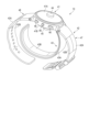
本実施形態に係る測定装置である血圧測定装置10の構造例について説明する。図4は、血圧測定装置10の構造の一例を示す斜視図である。図4の一例では、血圧測定装置10は、ユーザの手首に装着される腕時計型ウェアラブルデバイスである。図4に示すように、血圧測定装置10は、本体41と、ベルト42と、カフユニット43と、導電体44と、導電体45とを備える。手首は、被装着部位の一例である。導電体44及び導電体45は、心電測定用電極として機能する。
2.2.2 Structural Example of Blood Pressure Measuring Device A structural example of the blood
本体41は、例えば、略短円筒形状である。本体41の側面には、一対のベルト42が取付けられている。一対のベルト42のそれぞれは、一端が本体41の側面に取付けられている。一対のベルト42は、本体41において互いに対して反対側の側面に接続されている。
The
本体41は、血圧測定装置10の複数の要素を搭載可能に構成されている。本体41には、例えば、制御部21と、記憶部22と、通信部23と、操作部24と、表示部25と、電池29と、第1電極30と、第2電極31と、検出回路32とが搭載されている。
本体41は、表面41Aと、裏面41Bとを備える。表面41Aと裏面41Bは、互いに対して反対側を向く。血圧測定装置10は、表面41Aが外側を向く状態で、ユーザの手首に装着される。血圧測定装置10がユーザの手首に装着された状態では、裏面41Bは、内側を向き、ユーザの手首の皮膚に対向する。表面41Aは、第1の面の一例である。裏面41Bは、第2の面の一例である。
The
表面41Aには、例えば、表示画面が設けられる。表面41Aは、表示部25として機能する。表示画面は、例えば、LCD(Liquid Crystal Display)である。表示画面は、有機EL(Electro Luminescence)ディスプレイであってもよい。また、表示画面は、LED(Light Emitting Diode)を備えていてもよい。表示画面は、種々の情報を表示する機能を備えていればよく、これらに限定されるものではない。
For example, a display screen is provided on the surface 41A. 41 A of surfaces function as the
本体41の側面には、複数の押しボタン46が設けられている。押しボタン46は、操作部24として機能する。押しボタン46では、血圧測定装置10に対する種々の指示が入力される。例えば、押しボタン46の中のある1つでは、血圧測定を開始させる指示が入力される。また、例えば、押しボタン46の中の別のある1つでは、血圧測定及び心電測定を開始させる指示が入力される。
A plurality of
血圧測定装置10は、操作部24として、押しボタン46の代わりに、感圧式(抵抗式)または近接式(静電容量式)のタッチパネル式スイッチを備えてもよい。操作部24は、血圧測定装置10に対する種々の指示を入力する機能を備えていればよく、これらに限定されるものではない。
The blood
ベルト42は、ユーザの手首に外側から巻き付け可能に構成されている。ベルト42は、第1ベルト部47と第2ベルト部48とを備える。第1ベルト部47と第2ベルト部48は、帯状に形成されている。第1ベルト部47と第2ベルト部48は、例えば、樹脂材料によって形成され、可撓性を有する。第1ベルト部47の一端は、本体41の側面に回動可能に接続されている。第1ベルト部47の他端には、締結部材が取付けられている。第2ベルト部48の一端は、本体41の側面において第1ベルト部47が接続される側とは反対側に回動可能に接続されている。第1ベルト部47の締結部材に第2ベルト部48が係合することにより、第1ベルト部47と第2ベルト部48が締結される。第1ベルト部47と第2ベルト部48が締結されることにより、ユーザの手首に血圧測定装置10が装着される。
The
ベルト42は、外向面42Aと、内向面42Bとを有する。外向面42Aと内向面42Bは、互いに対して反対側を向く。血圧測定装置10がユーザの手首に装着された状態では、ベルト42の外向面42Aは、外側を向く。また、血圧測定装置10がユーザの手首に装着された状態では、ベルト42の内向面42Bは、内側を向く。
The
カフユニット43は、帯状の空気袋である。カフユニット43は、一端が本体41の側面に回動可能に取付けられている。カフユニット43は、ベルト42の内向面42Bに対向して配置される。カフユニット43の他端は、自由端である。このため、カフユニット43は、ベルト42の内周面から離間自在である。血圧測定装置10がユーザの手首Hに装着された状態では、カフユニット43は、ベルト42の内向面42Bとユーザの手首の間に延設される。
The
カフユニット43は、押圧カフ26として機能する。カフユニット43は、例えば、可撓性チューブを介してポンプ27と接続されている。カフユニット43には、可撓性チューブを通して、本体41から流体が供給される。流体は、例えば、空気である。カフユニット43は、本体41のポンプ27から流体が供給されることにより、膨張する。また、カフユニット43は、カフユニット43内から空気が排出されることにより、収縮する。血圧測定装置10が装着された状態でカフユニット43に流体が供給されると、カフユニット43の膨張によって、ユーザの手首が圧迫される。
The
カフユニット43は、外向面43Aと、内向面43Bと、を有する。内向面43Bは、外向面 43Aとは反対側を向く。カフユニット43の外向面43Aは、ベルト42の内向面42Bと対向する。内向面43Bは、血圧測定装置10が手首に装着された状態において、手首の皮膚と対向する。すなわち、内向面43Bの一部は、血圧測定装置10において、被装着部位に装着された状態で被装着部位の皮膚と対向する部位の一部を形成する。したがって、図4の一例では、血圧測定装置10が装着された状態において、本体41の裏面41B及びカフユニット43の内向面43Bが、ユーザの手首の皮膚に対向する。
The
導電体44は、本体41の表面41Aに取付けられている。導電体44は、電気的導電性を有する。導電体44は、本体41の内部において電池29と電気的に接続される。導電体44は、電池29から電力が供給されることにより、第1電極30として機能する。第1電極30は、血圧測定装置10を被装着部位に装着した状態で外部に露出する位置に配置されればよい。したがって、導電体44は、例えば、本体41の側面又はベルト42の外向面42A等に配置されてもよい。
A
導電体45は、本体41の裏面41Bに取付けられている。導電体45は、電気的導電性を有する。導電体45は、本体41の内部において電池29と電気的に接続される。導電体45は、電池29から電力が供給されることにより、第2電極31として機能する。第2電極31は、血圧測定装置10を被装着部位に装着した状態で、被装着部位の皮膚に対向する位置に配置されればよい。したがって、導電体45は、例えば、カフユニット43の内向面43Bに配置されてもよい。
The
2.3 機能構成例
次に、本実施形態に係る血圧測定システムの機能構成の一例について説明する。
2.3 Example of Functional Configuration Next, an example of the functional configuration of the blood pressure measurement system according to this embodiment will be described.
2.3.1 血圧測定装置の機能構成例
図5は、本実施形態に係る血圧測定システムの血圧測定装置10の機能構成の一例を模式的に示すブロック図である。
2.3.1 Functional Configuration Example of Blood Pressure Measuring Device FIG. 5 is a block diagram schematically showing an example of the functional configuration of the blood
血圧測定装置10の制御部21は、記憶部22の不揮発性メモリに記憶された心電測定プログラムを記憶部22の揮発性メモリに展開する。そして、制御部21は、揮発性メモリに展開された心電測定プログラムを解釈及び実行することで、圧力取得部61、血圧算出部62、押圧カフ制御部63、電力制御部64、電流取得部65、心電波形生成部66、及び、出力部67として機能する。
The
記憶部22の揮発性メモリは、圧力情報記憶部71、検出情報記憶部72、血圧情報記憶部73、心電情報記憶部74、及び、設定情報記憶部75として機能する。
The volatile memory of the
圧力情報記憶部71には、圧力情報が記憶される。圧力情報は、圧力センサ28で検出された押圧カフ26内の圧力を含む。
Pressure information is stored in the pressure
検出情報記憶部72には、検出回路32で検出された検出情報が記憶される。検出情報は、第1電極30及び第2電極31の間に流れる電流の電流値を含む。
Detection information detected by the
血圧情報記憶部73には、血圧情報が記憶される。血圧情報は、血圧値を含む。血圧値は、最高血圧、最低血圧、又はその他の指数である。また、血圧情報は、各血圧値についての測定日時及び測定場所を含むことができる。
Blood pressure information is stored in the blood pressure
心電情報記憶部74には、心電情報が記憶される。心電情報は、心電波形表示データ等を含む。
The electrocardiographic
設定情報記憶部75には、心電測定処理に用いられる各設定情報が記憶されている。設定情報は、心電測定処理に用いられる閾値などを含む。
The setting
圧力取得部61は、押圧カフ26内の圧力(カフ圧)を取得する。圧力取得部61は、例えば、圧力センサ28から、押圧カフ26内の圧力を取得する。圧力取得部61は、取得した圧力を、圧力情報として、記憶部22の圧力情報記憶部71に記憶する。
The
血圧算出部62は、圧力取得部61で取得された圧力情報に基づいて、血圧値を算出する。血圧値は、例えば、最高血圧、最低血圧、及びその他の指数である。血圧算出部62は、オシロメトリック法を用いて、被装着部位の圧迫時における圧力変動に基づいて、すなわち、押圧カフ26の加圧過程又は減圧過程の圧力の変動から、血圧値を算出する。血圧算出部62は、算出した血圧値を、血圧情報として、記憶部22の血圧情報記憶部73に記憶する。
The
押圧カフ制御部63は、圧力取得部61で取得された圧力情報に基づいて、押圧カフ26の状態を制御する。押圧カフ制御部63は、例えば、ポンプ27の駆動を制御することにより、押圧カフ26に供給する流体の量を制御する。押圧カフ制御部63は、カフ圧制御部の一例である。
The pressure
電力制御部64は、電池29から第1電極30及び第2電極31に供給する電力を制御する。電力制御部64は、圧力取得部61で取得された圧力情報に基づいて、第1電極30及び第2電極31に供給する電力を制御してもよい。
The
電流取得部65は、検出情報を取得する。検出情報は、例えば、検出回路32で検出された電流の電流値を含む。電流取得部65は、取得した検出情報を、記憶部22の検出情報記憶部72に記憶する。電流取得部65は、心電検出情報取得部の一例である。また、電流取得部65は、心電測定部の一例である。
The
心電波形生成部66は、圧力取得部61で取得された圧力情報と、電流取得部65で取得された検出情報とに基づいて、心電波形表示データを生成する。心電波形表示データは、表示部25に表示させるための画像データである。心電波形表示データは、心電情報として、記憶部22の心電情報記憶部74に記憶される。心電波形生成部66は、生成部の一例である。また、心電波形生成部66は、心電測定部の一例である。
The electrocardiographic
心電波形生成部66は、心電測定時間を設定する。心電測定時間は、心電測定処理において押圧カフ26の加圧過程の終了時から減圧過程の開始時までの間の時間である。これにより、心電波形生成部66は、加圧過程と減圧過程の間に、加圧状態保持過程を設定する。心電測定時間は、例えば、診断に有用な心電波形を得るために必要な測定時間である。心電測定時間は、例えば、10秒である。心電測定時間は、加圧状態保持過程の継続時間の一例である。心電測定時間は、例えば、記憶部22の設定情報記憶部75に記憶されている。
The
心電波形生成部66は、加圧過程から減圧過程にかけて、検出情報を取得する。心電波形生成部66は、取得した検出情報のうち、加圧過程及び減圧過程における検出結果をノイズであると判断する。そして、心電波形生成部66は、ノイズであると判断された検出結果を除外して、心電波形表示データを生成する。このため、例えば、押圧カフ26の加圧過程及び減圧過程における、検出回路32での検出結果は、心電波形表示データに反映されない。したがって、心電波形生成部66は、加圧状態保持過程において検出回路32で検出された電流値のみに基づいて、心電波形表示データを生成する。
The
出力部67は、血圧算出部62で算出された血圧情報を表示部25に出力し、表示部25に血圧の測定結果を表示させる。また、出力部67は、心電波形生成部66で生成された心電波形表示データを表示部25に出力し、表示部25に心電の測定結果を表示させる。
The
2.4 動作例
次に、本実施形態に係る血圧測定システムの動作例について説明する。なお、以下で説明する処理手順は一例に過ぎず、各処理は可能な限り変更されてよい。また、以下で説明する処理手順について、実施の形態に応じて、適宜、ステップの省略、置換、及び追加が可能である。
2.4 Operation Example Next, an operation example of the blood pressure measurement system according to this embodiment will be described. Note that the processing procedure described below is merely an example, and each processing may be changed as much as possible. Further, in the processing procedures described below, steps can be omitted, replaced, and added as appropriate according to the embodiment.
2.4.1 血圧測定システムの動作例
図6は、本実施形態に係る血圧測定システムを用いた心電測定における、血圧測定装置10の制御部21による処理の手順の一例を示すフローチャートである。制御部21は、例えば、血圧測定装置10をユーザの被装着部位に装着した状態で、血圧測定装置10の操作部24において心電の測定を開始させる指示が入力されたことに基づいて、心電測定処理を開始する。心電測定処理では、ユーザの血圧及び心電が測定され、血圧の測定結果及び心電の測定結果が表示部25に表示される。
2.4.1 Operation Example of Blood Pressure Measurement System FIG. 6 is a flowchart showing an example of a procedure of processing by the
図7及び図8は、図4の一例に示す血圧測定装置10をユーザの手首Hに装着した状態を示す図である。図7は、心電測定処理において押圧カフ26が膨張していない状態を示す。図8は、心電測定処理において押圧カフ26が膨張した状態を示す。手首Hは、被装着部位の一例である。
7 and 8 are diagrams showing a state in which the blood
心電測定処理では、制御部21は、まず、第1電極30及び第2電極31への電力の供給を開始する(S101)。このとき、制御部21は、ユーザに心電測定操作を促す表示を、例えば表示部25に表示させてもよい。制御部21は、ユーザに心電測定操作を促す表示として、例えば、「心電測定を開始して下さい」又は「測定ボタンを押して下さい」などと表示部25に表示させる。表示部25での表示の代わりに、音声や点灯表示等を用いて心電測定操作を促してもよい。
In the electrocardiographic measurement process, the
心電測定操作では、ユーザは、血圧測定装置10を被装着部位に装着した状態で、血圧測定装置10が装着されていない方の腕の指を、第1電極30に接触させる。第2電極31がユーザの被装着部位の皮膚に適切に接触した状態で心電測定操作が行われることにより、ユーザの心臓を介して第1電極30及び第2電極31の間に電流が流れる。検出回路32は、第1電極30及び第2電極31の間に流れる電流を検出し、検出結果を制御部21に出力する。
In the electrocardiogram measurement operation, the user touches the
次に、制御部21は、ユーザによる心電測定操作が行われたか否かを判断する(S102)。これにより、制御部21は、心電の測定を開始させるための操作が行われたか否かを判断する。制御部21は、心電測定操作が行われるまで、待機する。例えば、制御部21は、検出回路32で検出された電流波形が所定の挙動を示したことに基づいて、心電測定操作が行われたと判断する。
Next, the
心電測定操作が行われると(S102-Yes)、制御部21は、押圧カフ26の加圧を開始する(S103)。このとき、制御部21は、ポンプ27から押圧カフ26への空気の供給を開始させることにより、押圧カフ26の加圧を開始する。これにより、押圧カフ26の加圧過程が開始する。
When the electrocardiogram measurement operation is performed (S102-Yes), the
次に、制御部21は、圧力センサ28で検出された圧力Pが第1閾値Pth1以上であるか否かを判断する(S104)。すなわち、制御部21は、押圧カフ26内の圧力が所定の値以上であるか否かを判断する。第1閾値Pth1は、血圧の測定において押圧カフ26の加圧を終了する際の所定の圧力値である。第1閾値Pth1は、例えば、記憶部22の設定情報記憶部75に記憶されている。
Next, the
圧力Pが第1閾値Pth1より小さい場合(S104-No)、制御部21は、S104の判断を繰り返す。すなわち、制御部21は、押圧カフ26内の圧力が所定の値以上となるまで、押圧カフ26の加圧を継続する。圧力Pが第1閾値Pth1以上である場合(S104-Yes)、制御部21は、押圧カフ26によってユーザの手首Hが充分に圧迫されていると判断する。そして、制御部21は、押圧カフ26の加圧を停止する(S105)。このとき、制御部21は、ポンプ27から押圧カフ26への空気の供給を停止させることにより、押圧カフ26の加圧を停止する。これにより、押圧カフ26の加圧過程が終了する。
If the pressure P is smaller than the first threshold value Pth1 (S104-No), the
図7の一例に示すように、カフユニット43が膨張していない状態では、導電体45はユーザの手首Hに充分に密着していない。すなわち、押圧カフ26が充分に加圧されていない状態では、第2電極31はユーザの被装着部位に充分に密着しない。カフユニット43が加圧されることにより、導電体45はカフユニット43の膨張によって内側に向かって押圧され、ユーザの手首Hの皮膚に外側から押し付けられる。これにより、導電体45のユーザの手首Hへの密着強度が大きくなる。
As shown in the example of FIG. 7, the
図8の一例に示すように、カフユニット43内の圧力Pが第1閾値Pth1以上である場合には、導電体45がユーザの手首Hに充分な密着強度で接触する。すなわち、押圧カフ26が充分に加圧された状態では、第2電極31がユーザの被装着部位に適切に接触する。
As shown in an example of FIG. 8, when the pressure P in the
次に、制御部21は、圧力Pが第1閾値Pth1以上であると判断された時点の時刻を基準時刻T0として設定する(S106)。基準時刻T0は、押圧カフ26の加圧過程の終了時の時刻である。制御部21は、基準時刻T0からの経過時間dTを、継続的に取得する。
Next, the
次に、制御部21は、経過時間dTが閾値Tth以上であるか否かを判断する(S107)。閾値Tthは、心電測定時間の一例であり、加圧状態保持過程の継続時間の一例である。閾値Tthは、例えば、記憶部22の設定情報記憶部75に記憶されている。制御部21は、経過時間dTが閾値Tth以上であるか否かを判断することにより、加圧状態保持過程において心電測定時間が経過したか否かを判断する。加圧状態保持過程では、第2電極31がユーザの被装着部位に適切に接触した状態が維持される。
Next, the
経過時間dTが閾値Tthより小さい場合(S107-No)、制御部21は、S107の判断を繰り返す。すなわち、制御部21は、加圧状態保持過程において心電測定時間が経過するまで、待機する。
If the elapsed time dT is smaller than the threshold Tth (S107-No), the
経過時間dTが閾値Tth以上である場合(S107-Yes)、制御部21は、加圧状態保持過程において、心電測定時間が経過したと判断する。そして、制御部21は、押圧カフ26の減圧を開始する(S108)。このとき、制御部21は、押圧カフ26から空気を流出させることにより、押圧カフ26の減圧を開始する。これにより、押圧カフ26の減圧過程が開始する。押圧カフ26から空気が流出するにつれて、押圧カフ26は膨張した状態から収縮し、これにともなって、押圧カフ26からユーザの手首Hへの圧迫が緩和される。
If the elapsed time dT is equal to or greater than the threshold Tth (S107-Yes), the
次に、制御部21は、圧力センサ28で検出された圧力Pが第2閾値Pth2以下であるか否かを判断する(S109)。すなわち、制御部21は、押圧カフ26内の圧力が所定の値以下であるか否かを判断する。第2閾値Pth2は、血圧の測定において押圧カフ26の減圧過程を終了する際の所定の圧力値である。第2閾値Pth2は、例えば、記憶部22の設定情報記憶部75に記憶されている。
Next, the
圧力Pが第2閾値Pth2より大きい場合(S109-No)、制御部21は、S109の判断を繰り返す。すなわち、制御部21は、押圧カフ26内の圧力が所定の値以下となるまで、押圧カフ26の減圧を継続する。圧力Pが第2閾値Pth2以下である場合(S109-Yes)、制御部21は、押圧カフ26の減圧を停止する(S110)。このとき、制御部21は、押圧カフ26からの空気の流出を停止させることにより、押圧カフ26の減圧を停止する。これにより、押圧カフ26の減圧過程が終了する。
If the pressure P is greater than the second threshold value Pth2 (S109-No), the
次に、制御部21は、圧力センサ28で検出された押圧カフ26内の圧力Pに基づいて、血圧値を算出する(S111)。制御部21は、例えば、S103からS110までの間において取得した押圧カフ26内の圧力Pの変動に基づいて、オシロメトリック法によって、最高血圧及び最低血圧を算出する。制御部21は、最高血圧及び最低血圧に基づいて、血圧の平均値、代表値などの他の指数を算出してもよい。制御部21は、算出した血圧値を、記憶部22の血圧情報記憶部73に記憶する。
Next, the
なお、S111の血圧算出処理は、押圧カフ26の加圧過程の開始(S103)から押圧カフ26の減圧過程の終了(S110)までの期間において継続的に行われてもよい。また、S111の血圧の算出処理は、押圧カフ26の加圧過程における押圧カフ26内の圧力Pの検出結果のみに基づいて行われてもよく、押圧カフ26の減圧過程における押圧カフ26内の圧力Pの検出結果のみに基づいて行われてもよい。
The blood pressure calculation process of S111 may be continuously performed during the period from the start of the process of pressurizing the pressure cuff 26 (S103) to the end of the process of depressurization of the pressure cuff 26 (S110). Further, the blood pressure calculation processing in S111 may be performed based only on the detection result of the pressure P in the
次に、制御部21は、心電波形表示データを生成する(S112)。制御部21は、押圧カフ26の加圧の停止時から押圧カフ26の減圧の開始時までに取得された検出回路32での検出結果のみを用いて、心電波形表示データを生成する。制御部21は、例えば、加圧開始時(S103)から減圧終了時(S111)までの間における検出回路32での検出結果のうち、押圧カフ26の加圧過程及び減圧過程における検出結果をノイズであると判断し、加圧状態保持過程における検出結果のみが反映された心電波形表示データを生成する。制御部21は、生成した心電波形表示データを、心電測定の測定結果として、記憶部22の心電情報記憶部74に記憶する。
Next, the
次に、制御部21は、血圧測定の測定結果と、心電測定の測定結果とを、表示部25に表示させる(S113)。制御部21は、例えば、血圧の算出(S111)において算出された最高血圧及び最低血圧を、血圧の測定結果として、表示部25に表示させる。また、制御部21は、例えば、心電波形表示データの生成(S112)において生成された心電波形表示データを、心電測定の測定結果として、表示部25に表示させる。
Next, the
2.5 作用・効果
次に、本実施形態に係る血圧測定システムの作用及び効果の一例について説明する。
2.5 Actions and Effects Next, an example of actions and effects of the blood pressure measurement system according to this embodiment will be described.
図9は、図6の一例に示す心電測定処理における検出回路32による検出結果の一例を示す図である。図9の一例では、検出回路32による検出結果は、心電波形Aを含む。心電波形Aの横軸は、時間Tである。また、心電波形Aの縦軸は、電流Iである。
FIG. 9 is a diagram showing an example of detection results by the
心電波形Aは、第1領域A1と、第2領域A2と、第3領域A3とを有する。第1領域A1は、加圧過程における検出結果に基づく。第2領域A2は、加圧状態保持過程における検出結果に基づく。第3領域A3は、減圧過程における検出結果に基づく。 The electrocardiographic waveform A has a first area A1, a second area A2, and a third area A3. The first area A1 is based on the detection result in the pressurization process. The second area A2 is based on the detection result in the pressurized state holding process. The third area A3 is based on the detection results during the pressure reduction process.
ここで、心電の測定において、電極が被装着部位の皮膚に適切に接触していない状態では、適切な測定結果が得られないことが知られている。例えば、図7の一例に示すように、押圧カフ26の加圧過程及び減圧過程には、第2電極31がユーザの手首Hに充分な密着強度で接触しない可能性がある。このため、図9の一例に示すように、押圧カフ26の加圧過程の検出結果に基づく心電波形(第1領域A1)、及び、押圧カフ26の減圧過程の検出結果に基づく心電波形(第3領域A3)は、不安定に変動しノイズとみなすことが好ましい。
In electrocardiogram measurement, it is known that appropriate measurement results cannot be obtained if the electrodes are not in proper contact with the skin of the attachment site. For example, as shown in an example of FIG. 7, there is a possibility that the
一方、心電の測定において、電極が被装着部位の皮膚に対して適切に押圧された状態では、適切な測定結果を得ることができる。例えば、図8の一例に示すように、血圧の測定において押圧カフ26が充分に加圧された状態では、第2電極31がユーザの手首Hに向かって充分な密着強度で押圧される。このため、例えば加圧状態保持過程のように押圧カフ26の加圧過程の終了後から減圧過程の開始までの期間における、検出結果に基づく心電波形(第2領域A2)は、図9の一例に示すように、比較的安定し、適切な検出結果として用いることができる。
On the other hand, in electrocardiogram measurement, appropriate measurement results can be obtained when the electrodes are appropriately pressed against the skin of the attachment site. For example, as shown in an example of FIG. 8 , when the
本実施形態では、押圧カフ26の加圧過程の後から減圧過程の開始までの間に加圧状態保持過程が設けられる。加圧状態保持過程における検出回路32での検出結果が反映された心電波形表示データが生成される。加圧状態保持過程では、押圧カフ26の膨張によって第2電極31がユーザの被装着部位の皮膚に適切に押圧された状態で、検出回路32での検出結果が取得される。すなわち、本実施形態によれば、心電測定用電極がユーザの被装着部位に適切に接触した状態を生成し、心電測定用電極がユーザの被装着部位に適切に接触した状態において心電測定を行うことができる。
In the present embodiment, a pressurized state holding process is provided after the pressurization process of the
また、本実施形態では、押圧カフ26の加圧過程から減圧過程までの検出回路32での検出結果が取得される。また、取得された検出結果のうち、押圧カフ26の加圧過程及び減圧過程における検出結果がノイズであると判断される。そして、押圧カフ26の加圧過程及び減圧過程を除いた検出結果のみを用いて、心電波形表示データが生成される。これにより、表示部には、心電測定の測定結果として、加圧状態保持過程での検出結果のみが反映された心電データのみが表示される。したがって、本実施形態によれば、心電波形が安定した状態における検出結果、すなわち、診断に有用な心電データのみが反映された心電波形を表示することができる。
In addition, in the present embodiment, the detection result of the
2.6 変形例
なお、血圧測定装置10の第2電極31がユーザの被装着部位に適切に接触した状態でのみ、心電の測定を行ってもよい。この変形例では、制御部21は、例えば、第1電極30及び第2電極31への電力の供給、及び、検出回路32での検出を行わずに、押圧カフ26の加圧を開始する。そして、例えば、押圧カフ26の加圧の停止後に、ユーザに対して心電測定操作を指示する表示を表示部25に表示させる。そして、心電測定操作が行われたことに基づいて、第1電極30及び第2電極31への電力の供給を開始し、検出回路32での検出を開始する。そして、心電測定操作が入力されてから心電測定時間が経過したことに基づいて、第1電極30及び第2電極31への電力の供給を停止するともに、押圧カフ26の減圧を開始する。
2.6 Modification The electrocardiogram may be measured only in a state where the
本変形例では、押圧カフ26の加圧の停止後に心電の測定が開始され、心電測定時間の経過後において押圧カフ26の減圧が開始されることにより、押圧カフ26の加圧の停止後から減圧の開始までの期間内においてのみ、検出回路32での検出結果の取得が行われる。これにより、押圧カフ26の膨張によって第2電極31がユーザの被装着部位の皮膚に適切に押圧された状態でのみ、検出回路32での検出結果の取得が行われる。したがって、心電波形が安定した状態における検出結果のみを用いて、心電波形表示データを生成することができる。本変形例によれば、適切な心電の測定結果を取得可能な時間においてのみ、心電測定のための電流をユーザに流す。このため、ユーザの体に電流を流す時間を不必要に長くすることなく、適切な心電波形のみを効果的に取得することができる。これにより、ユーザの体への負担を軽減することができる。
In this modified example, electrocardiogram measurement is started after the pressurization of the
3. 実施形態等の共通構成
測定装置(1:10)は、押圧カフ内の圧力を表す圧力情報を取得する圧力取得部(2:61)と、前記押圧カフを加圧する加圧過程と、前記加圧過程の終了後に前記押圧カフが加圧された状態を保持する加圧状態保持過程と、前記加圧状態保持過程の終了後に前記押圧カフを減圧する減圧過程とのそれぞれにおける前記押圧カフ内の圧力を、前記圧力情報に基づいて制御するカフ圧制御部(3:63)と、前記圧力情報に基づいて、ユーザの血圧を算出する血圧算出部(4:62)と、前記加圧状態保持過程における前記ユーザの心電を測定する心電測定部(5:65,66)と、を備える。
3. Common configuration of embodiments etc. A measuring device (1:10) includes a pressure acquisition unit (2:61) that acquires pressure information representing the pressure in the pressure cuff, a pressurization process that pressurizes the pressure cuff, and the pressure cuff. The inside of the pressure cuff in each of a pressurized state maintaining process in which the pressurized cuff is maintained in a pressurized state after the pressurization process and a decompression process in which the pressure cuff is decompressed after the pressurized state retaining process. A cuff pressure control unit (3:63) that controls pressure based on the pressure information, a blood pressure calculation unit (4:62) that calculates the user's blood pressure based on the pressure information, and the pressurized state holding unit. an electrocardiogram measuring unit (5:65, 66) for measuring the electrocardiogram of the user in the process.
なお、本発明は、上記実施形態に限定されるものではなく、実施段階ではその要旨を逸脱しない範囲で種々に変形することが可能である。また、各実施形態は適宜組み合わせて実施してもよく、その場合組み合わせた効果が得られる。更に、上記実施形態には種々の発明が含まれており、開示される複数の構成要件から選択された組み合わせにより種々の発明が抽出され得る。例えば、実施形態に示される全構成要件からいくつかの構成要件が削除されても、課題が解決でき、効果が得られる場合には、この構成要件が削除された構成が発明として抽出され得る。 It should be noted that the present invention is not limited to the above-described embodiments, and various modifications can be made in the implementation stage without departing from the scope of the invention. Further, each embodiment may be implemented in combination as appropriate, in which case the combined effect can be obtained. Furthermore, various inventions are included in the above embodiments, and various inventions can be extracted by combinations selected from a plurality of disclosed constituent elements. For example, even if some constituent elements are deleted from all the constituent elements shown in the embodiments, if the problem can be solved and effects can be obtained, the configuration with the constituent elements deleted can be extracted as an invention.
[付記]
前記実施形態の一部または全部は、特許請求の範囲のほか以下の付記に示すように記載することも可能であるが、これに限られない。
[Appendix]
Some or all of the above embodiments can be described as described in the following appendices in addition to the scope of claims, but are not limited to this.
(付記1)
ハードウェアプロセッサ(21)とメモリ(22)とを有する測定装置であって、
前記ハードウェアプロセッサ(21)は、
押圧カフ内の圧力を表す圧力情報を取得し、前記取得した圧力情報を前記メモリ(22)に記憶させ、
前記押圧カフを加圧する加圧過程と、前記加圧過程の終了後に前記押圧カフが加圧された状態を保持する加圧状態保持過程と、前記加圧状態保持過程の終了後に前記押圧カフを減圧する減圧過程とのそれぞれにおける前記押圧カフ内の圧力を、前記メモリ(22)に記憶された圧力情報に基づいて制御し、
前記メモリ(22)に記憶された圧力情報に基づいて、ユーザの血圧を算出し、前記算出した血圧を前記メモリ(22)に記憶させ、
前記加圧状態保持過程における前記ユーザの心電を測定し、前記測定した心電を前記メモリ(22)に記憶させる、
測定装置。
(Appendix 1)
A measuring device comprising a hardware processor (21) and a memory (22), comprising:
The hardware processor (21)
acquiring pressure information representing the pressure in the pressure cuff, storing the acquired pressure information in the memory (22);
A pressurization process of pressurizing the pressurization cuff, a pressurization state holding process of holding the pressurized state of the pressurization cuff after the pressurization process, and a pressurization cuff after the pressurization state holding process. controlling the pressure in the pressure cuff in each of the decompression process of decompressing based on the pressure information stored in the memory (22);
calculating the user's blood pressure based on the pressure information stored in the memory (22), storing the calculated blood pressure in the memory (22);
measuring the electrocardiogram of the user in the pressurized state holding process, and storing the measured electrocardiogram in the memory (22);
measuring device.
1…血圧測定装置
2…圧力取得部
3…押圧カフ制御部
4…血圧算出部
5…心電測定部
6…出力部
10…血圧測定装置
11…携帯端末
12…医師端末
13…サーバ
21…制御部
22…記憶部
23…通信部
24…操作部
25…表示部
26…押圧カフ
27…ポンプ
28…圧力センサ
29…電池
30,31…電極
32…検出回路
41…本体
41A…表面
41B…裏面
42…ベルト
42A…外向面
42B…内向面
43…カフユニット
43A…外向面
43B…内向面
44,45…導電体
46…押しボタン
47,48…ベルト部
61…圧力取得部
62…血圧算出部
63…押圧カフ制御部
64…電力制御部
65…電流取得部
66…心電波形生成部
67…出力部
71…圧力情報記憶部
72…検出情報記憶部
73…血圧情報記憶部
74…心電情報記憶部
75…設定情報記憶部
A…心電波形
REFERENCE SIGNS
Claims (11)
前記本体に取り付けられ、ユーザの被装着部位に巻き付け可能なベルトと、
前記本体の側面に取り付けられ、前記ベルトと前記ユーザの被装着部位との間に延設される押圧カフと、
前記押圧カフ内の圧力を表す圧力情報を取得する圧力取得部と、
前記押圧カフを加圧する加圧過程と、前記加圧過程の終了後に前記押圧カフが加圧された状態を保持する加圧状態保持過程と、前記加圧状態保持過程の終了後に前記押圧カフを減圧する減圧過程とのそれぞれにおける前記押圧カフ内の圧力を、前記圧力情報に基づいて制御するカフ圧制御部と、
前記圧力情報に基づいて、ユーザの血圧を算出する血圧算出部と、
前記加圧状態保持過程における前記ユーザの心電を測定する心電測定部と、
一対の心電測定用電極として第1電極と第2電極と、を備え、
前記カフ圧制御部は、前記加圧状態保持過程における前記押圧カフ内の圧力を前記加圧過程の終了時における圧力に保持し、
前記第2電極は、前記押圧カフが前記ユーザに装着された状態において前記ユーザの被装着部位の皮膚に接触する位置に配置され、
前記被装着部位は、前記押圧カフが装着される部位であり、
前記第2電極は、前記本体の前記第2の面に配置され、前記加圧状態保持過程において、膨張した前記押圧カフによって前記被装着部位に押し付けられる、
測定装置。 a main body having a first surface on which a display portion is provided and a second surface that is the back surface of the first surface;
a belt that is attached to the main body and can be wrapped around a wearing part of a user;
a pressure cuff attached to the side surface of the main body and extending between the belt and the wearing part of the user;
a pressure acquisition unit that acquires pressure information representing the pressure in the pressure cuff;
A pressurization process of pressurizing the pressurization cuff, a pressurization state holding process of holding the pressurized state of the pressurization cuff after the pressurization process, and a pressurization cuff after the pressurization state holding process. a cuff pressure control unit that controls the pressure in the pressure cuff in each of the pressure reduction process and the pressure reduction process based on the pressure information;
a blood pressure calculation unit that calculates the user's blood pressure based on the pressure information;
an electrocardiogram measuring unit that measures the electrocardiogram of the user in the pressurized state holding process;
comprising a first electrode and a second electrode as a pair of electrocardiographic measurement electrodes,
The cuff pressure control unit maintains the pressure in the pressure cuff during the pressurization state holding process at the pressure at the end of the pressurization process,
The second electrode is arranged at a position in contact with the skin of the user's wearing site when the pressure cuff is worn by the user,
The attached part is a part to which the pressure cuff is attached,
The second electrode is arranged on the second surface of the main body, and is pressed against the attachment site by the inflated pressure cuff in the process of maintaining the pressurized state.
measuring device.
前記一対の心電測定用電極間で前記ユーザの心臓を介して流れる電流の電流値を表す検出情報を取得する心電検出情報取得部と、
前記心電検出情報取得部が取得した検出情報に基づいて、前記加圧状態保持過程における前記検出情報を反映した心電波形を生成する生成部と、
を備える、請求項1に記載の測定装置。 The electrocardiogram measurement unit
an electrocardiogram detection information acquisition unit that acquires detection information representing a current value of current flowing through the user's heart between the pair of electrocardiogram measurement electrodes;
a generation unit that generates an electrocardiographic waveform that reflects the detection information in the pressurized state holding process based on the detection information acquired by the electrocardiogram detection information acquisition unit;
2. The measuring device according to claim 1, comprising:
前記生成部は、前記取得した検出情報のうち、前記加圧状態保持過程に取得された検出情報のみを反映した心電波形を生成する、請求項4に記載の測定装置。 The electrocardiogram detection information acquisition unit acquires the detection information from the pressurization process to the decompression process,
5. The measuring device according to claim 4, wherein said generator generates an electrocardiographic waveform reflecting only the detection information acquired in said pressurized state holding process among said acquired detection information.
前記心電検出情報取得部は、前記検出情報として、前記第1電極及び前記第2電極の間で前記ユーザの心臓を介して流れる電流を検出する、請求項4に記載の測定装置。 The first electrode is arranged at a position where it does not contact the skin of the wearing part of the user when the pressure cuff is worn by the user,
5. The measuring device according to claim 4, wherein the electrocardiographic detection information acquiring unit detects, as the detection information, a current flowing through the user's heart between the first electrode and the second electrode.
前記第1電極は、前記本体の前記第1の面に配置される、請求項7に記載の測定装置。 The pressure cuff is pressurized while being worn by the user, so that the user's wearing part can be pressed from the outside ,
8. The measuring device of claim 7, wherein the first electrode is arranged on the first side of the body.
前記押圧カフ内の圧力を表す圧力情報を取得する過程と、
前記押圧カフを加圧する加圧過程と、前記加圧過程の終了後に前記押圧カフ内の圧力が前記加圧過程の終了時における圧力に保持されるように前記押圧カフが加圧された状態を保持する加圧状態保持過程と、前記加圧状態保持過程の終了後に前記押圧カフを減圧する減圧過程とのそれぞれにおける前記押圧カフ内の圧力を、前記圧力情報に基づいて制御する過程と、
前記圧力情報に基づいて、前記ユーザの血圧を算出する過程と、
前記加圧状態保持過程における前記ユーザの心電を測定する過程と、
を備え、
前記第2電極は、前記押圧カフが前記ユーザに装着された状態において前記ユーザの被装着部位の皮膚に接触する位置に配置され、
前記被装着部位は、前記押圧カフが装着される部位であり、
前記第2電極は、前記本体の前記第2の面に配置され、前記加圧状態保持過程において、膨張した前記押圧カフによって前記被装着部位に押し付けられる、
測定方法。 a main body having a first surface on which a display portion is provided and a second surface that is the back side of the first surface; a belt that is attached to the main body and can be wrapped around a user's wearing part; a pressure cuff attached to the side surface of the user and extending between the belt and the user's wearing site; A measurement method for measuring blood pressure and electrocardiogram,
obtaining pressure information representative of the pressure within the pressure cuff;
A pressurization process of pressurizing the pressurization cuff, and a state in which the pressurization cuff is pressurized so that the pressure in the pressurization cuff is held at the pressure at the end of the pressurization process after the pressurization process is completed. a step of controlling the pressure in the pressure cuff based on the pressure information in each of a pressurized state holding process to be held and a decompression process of depressurizing the press cuff after the pressurized state holding process is completed;
calculating the user's blood pressure based on the pressure information;
a process of measuring the electrocardiogram of the user in the pressurized state holding process;
with
The second electrode is arranged at a position in contact with the skin of the user's wearing site when the pressure cuff is worn by the user,
The attached part is a part to which the pressure cuff is attached,
The second electrode is arranged on the second surface of the main body, and is pressed against the attachment site by the inflated pressure cuff in the process of maintaining the pressurized state.
Measuring method.
Priority Applications (5)
| Application Number | Priority Date | Filing Date | Title |
|---|---|---|---|
| JP2018155466A JP7230369B2 (en) | 2018-08-22 | 2018-08-22 | Measuring device, measuring method and measuring program |
| DE112019003679.3T DE112019003679T5 (en) | 2018-08-22 | 2019-07-24 | MEASURING DEVICE, MEASURING METHOD AND MEASURING PROGRAM |
| CN201980050192.8A CN112512415A (en) | 2018-08-22 | 2019-07-24 | Measurement device, measurement method, and measurement program |
| PCT/JP2019/029026 WO2020039830A1 (en) | 2018-08-22 | 2019-07-24 | Measurement device, measurement method, and measurement program |
| US17/176,747 US20210161399A1 (en) | 2018-08-22 | 2021-02-16 | Measurement device, measurement method, and non-transitory recording medium recording measurement program |
Applications Claiming Priority (1)
| Application Number | Priority Date | Filing Date | Title |
|---|---|---|---|
| JP2018155466A JP7230369B2 (en) | 2018-08-22 | 2018-08-22 | Measuring device, measuring method and measuring program |
Publications (3)
| Publication Number | Publication Date |
|---|---|
| JP2020028421A JP2020028421A (en) | 2020-02-27 |
| JP2020028421A5 JP2020028421A5 (en) | 2021-08-26 |
| JP7230369B2 true JP7230369B2 (en) | 2023-03-01 |
Family
ID=69592548
Family Applications (1)
| Application Number | Title | Priority Date | Filing Date |
|---|---|---|---|
| JP2018155466A Active JP7230369B2 (en) | 2018-08-22 | 2018-08-22 | Measuring device, measuring method and measuring program |
Country Status (5)
| Country | Link |
|---|---|
| US (1) | US20210161399A1 (en) |
| JP (1) | JP7230369B2 (en) |
| CN (1) | CN112512415A (en) |
| DE (1) | DE112019003679T5 (en) |
| WO (1) | WO2020039830A1 (en) |
Families Citing this family (4)
| Publication number | Priority date | Publication date | Assignee | Title |
|---|---|---|---|---|
| CN117202849A (en) * | 2021-05-28 | 2023-12-08 | 欧姆龙健康医疗事业株式会社 | Biological information measuring device |
| CN117136029A (en) * | 2021-05-28 | 2023-11-28 | 欧姆龙健康医疗事业株式会社 | Biological information measuring device and control method for biological information measuring device |
| CN117119960A (en) * | 2021-05-28 | 2023-11-24 | 欧姆龙健康医疗事业株式会社 | Biological information measuring device |
| JP2024014477A (en) * | 2022-07-22 | 2024-02-01 | オムロンヘルスケア株式会社 | Biological information measuring device |
Citations (9)
| Publication number | Priority date | Publication date | Assignee | Title |
|---|---|---|---|---|
| JP2001204696A (en) | 2000-01-31 | 2001-07-31 | Matsushita Electric Ind Co Ltd | Electronic sphygmomanometer |
| JP2004065336A (en) | 2002-08-02 | 2004-03-04 | Nec Access Technica Ltd | Biological phenomenon measuring apparatus |
| US20100130876A1 (en) | 2008-11-27 | 2010-05-27 | Samsung Electronics Co., Ltd. | Portable device for measuring blood pressure and method therefor |
| US20120283583A1 (en) | 2011-05-02 | 2012-11-08 | Izmail Batkin | Apparatus and method for electrocardiogram-assisted blood pressure measurement |
| JP2014036843A (en) | 2012-07-26 | 2014-02-27 | Chang-An Chou | Cardiovascular monitoring device |
| CN204500639U (en) | 2014-12-26 | 2015-07-29 | 深圳市安科瑞仪器有限公司 | Portable physiological parameter detector |
| WO2016119656A1 (en) | 2015-01-26 | 2016-08-04 | 周常安 | Cardiovascular health monitoring device and method |
| US20160235325A1 (en) | 2015-02-17 | 2016-08-18 | Chang-An Chou | Cardiovascular monitoring device |
| US20180206734A1 (en) | 2017-01-20 | 2018-07-26 | Kentec Inc. | Wrist type apparatus for measurement of cardiovascular health, system, and method thereof |
Family Cites Families (3)
| Publication number | Priority date | Publication date | Assignee | Title |
|---|---|---|---|---|
| TWI258359B (en) * | 2005-05-20 | 2006-07-21 | Dailycare Biomedical Inc | Apparatus for evaluating cardiovascular functions |
| JP2007195693A (en) * | 2006-01-25 | 2007-08-09 | Matsushita Electric Works Ltd | Portable electrocardiographic device |
| CN107949319A (en) * | 2015-07-08 | 2018-04-20 | 细胞保护装置股份有限公司 | The configurable system for adjusting (RIC) for performing remote ischemic to subject |
-
2018
- 2018-08-22 JP JP2018155466A patent/JP7230369B2/en active Active
-
2019
- 2019-07-24 WO PCT/JP2019/029026 patent/WO2020039830A1/en active Application Filing
- 2019-07-24 DE DE112019003679.3T patent/DE112019003679T5/en active Pending
- 2019-07-24 CN CN201980050192.8A patent/CN112512415A/en active Pending
-
2021
- 2021-02-16 US US17/176,747 patent/US20210161399A1/en active Pending
Patent Citations (9)
| Publication number | Priority date | Publication date | Assignee | Title |
|---|---|---|---|---|
| JP2001204696A (en) | 2000-01-31 | 2001-07-31 | Matsushita Electric Ind Co Ltd | Electronic sphygmomanometer |
| JP2004065336A (en) | 2002-08-02 | 2004-03-04 | Nec Access Technica Ltd | Biological phenomenon measuring apparatus |
| US20100130876A1 (en) | 2008-11-27 | 2010-05-27 | Samsung Electronics Co., Ltd. | Portable device for measuring blood pressure and method therefor |
| US20120283583A1 (en) | 2011-05-02 | 2012-11-08 | Izmail Batkin | Apparatus and method for electrocardiogram-assisted blood pressure measurement |
| JP2014036843A (en) | 2012-07-26 | 2014-02-27 | Chang-An Chou | Cardiovascular monitoring device |
| CN204500639U (en) | 2014-12-26 | 2015-07-29 | 深圳市安科瑞仪器有限公司 | Portable physiological parameter detector |
| WO2016119656A1 (en) | 2015-01-26 | 2016-08-04 | 周常安 | Cardiovascular health monitoring device and method |
| US20160235325A1 (en) | 2015-02-17 | 2016-08-18 | Chang-An Chou | Cardiovascular monitoring device |
| US20180206734A1 (en) | 2017-01-20 | 2018-07-26 | Kentec Inc. | Wrist type apparatus for measurement of cardiovascular health, system, and method thereof |
Also Published As
| Publication number | Publication date |
|---|---|
| WO2020039830A1 (en) | 2020-02-27 |
| DE112019003679T5 (en) | 2021-04-22 |
| JP2020028421A (en) | 2020-02-27 |
| CN112512415A (en) | 2021-03-16 |
| US20210161399A1 (en) | 2021-06-03 |
Similar Documents
| Publication | Publication Date | Title |
|---|---|---|
| JP7230369B2 (en) | Measuring device, measuring method and measuring program | |
| US9782098B2 (en) | Cardiovascular monitoring device | |
| EP3435204A1 (en) | Apparatus and method for measuring biometric information | |
| JP7124552B2 (en) | measuring device | |
| WO2021208745A1 (en) | Blood pressure measuring method and apparatus | |
| WO2018030125A1 (en) | Fatigue assessment device, fatigue assessment method, fatigue assessment program, and biological information measurement device | |
| CN110381819B (en) | Biological information measuring apparatus and storage medium | |
| JP2020028421A5 (en) | ||
| KR101990383B1 (en) | Blood pressure measuring apparatus for measuring electrocardiogram | |
| US11478160B2 (en) | Vital information measuring apparatus, method, and program | |
| CN112040852B (en) | Blood pressure measuring device | |
| WO2019111779A1 (en) | Bioinformation measurement device, wearing assistance method, and wearing assistance program | |
| TWI624246B (en) | Blood pressure measurement device and method thereof | |
| WO2017221938A1 (en) | Biological information measurement device, biological information measurement support method, and biological information measurement support program | |
| CN113507885A (en) | Blood pressure measurement device and blood pressure measurement method | |
| US20160235307A1 (en) | Cardiovascular monitoring device | |
| JP3174904U (en) | Wrist sphygmomanometer | |
| JP2019093006A (en) | Information processing device, information processing method, and information processing program | |
| US20200315529A1 (en) | Information processing device, biological information measuring device, method, and non-transitory recording medium in which program is stored | |
| JP2009072242A (en) | Biological information measuring apparatus | |
| EP3818936A1 (en) | Biometric device for the hand | |
| WO2019087633A1 (en) | Biological information measurement device, information processing device, biological information measurement method, and program | |
| JP2001070259A (en) | Sphygmomanometer with adipometer | |
| JP2020185104A (en) | Blood pressure measuring device | |
| CN117794443A (en) | Blood pressure measuring device and blood pressure measuring system |
Legal Events
| Date | Code | Title | Description |
|---|---|---|---|
| A521 | Request for written amendment filed |
Free format text: JAPANESE INTERMEDIATE CODE: A523 Effective date: 20210715 |
|
| A621 | Written request for application examination |
Free format text: JAPANESE INTERMEDIATE CODE: A621 Effective date: 20210715 |
|
| A131 | Notification of reasons for refusal |
Free format text: JAPANESE INTERMEDIATE CODE: A131 Effective date: 20220726 |
|
| A521 | Request for written amendment filed |
Free format text: JAPANESE INTERMEDIATE CODE: A523 Effective date: 20220905 |
|
| A131 | Notification of reasons for refusal |
Free format text: JAPANESE INTERMEDIATE CODE: A131 Effective date: 20221011 |
|
| A521 | Request for written amendment filed |
Free format text: JAPANESE INTERMEDIATE CODE: A523 Effective date: 20221201 |
|
| TRDD | Decision of grant or rejection written | ||
| RD02 | Notification of acceptance of power of attorney |
Free format text: JAPANESE INTERMEDIATE CODE: A7422 Effective date: 20230113 |
|
| A01 | Written decision to grant a patent or to grant a registration (utility model) |
Free format text: JAPANESE INTERMEDIATE CODE: A01 Effective date: 20230117 |
|
| A61 | First payment of annual fees (during grant procedure) |
Free format text: JAPANESE INTERMEDIATE CODE: A61 Effective date: 20230130 |
|
| R150 | Certificate of patent or registration of utility model |
Ref document number: 7230369 Country of ref document: JP Free format text: JAPANESE INTERMEDIATE CODE: R150 |