EP3059779A1 - Mechanism for confirming locked state of electrode contact of electric vehicle and apparatus for confirming locked state of battery module electrode - Google Patents
Mechanism for confirming locked state of electrode contact of electric vehicle and apparatus for confirming locked state of battery module electrode Download PDFInfo
- Publication number
- EP3059779A1 EP3059779A1 EP13895607.3A EP13895607A EP3059779A1 EP 3059779 A1 EP3059779 A1 EP 3059779A1 EP 13895607 A EP13895607 A EP 13895607A EP 3059779 A1 EP3059779 A1 EP 3059779A1
- Authority
- EP
- European Patent Office
- Prior art keywords
- positive locking
- electrode
- bolt
- positioning
- electric vehicle
- Prior art date
- Legal status (The legal status is an assumption and is not a legal conclusion. Google has not performed a legal analysis and makes no representation as to the accuracy of the status listed.)
- Withdrawn
Links
Images
Classifications
-
- H—ELECTRICITY
- H01—ELECTRIC ELEMENTS
- H01M—PROCESSES OR MEANS, e.g. BATTERIES, FOR THE DIRECT CONVERSION OF CHEMICAL ENERGY INTO ELECTRICAL ENERGY
- H01M50/00—Constructional details or processes of manufacture of the non-active parts of electrochemical cells other than fuel cells, e.g. hybrid cells
- H01M50/50—Current conducting connections for cells or batteries
- H01M50/543—Terminals
- H01M50/552—Terminals characterised by their shape
- H01M50/561—Hollow metallic terminals, e.g. terminal bushings
-
- B—PERFORMING OPERATIONS; TRANSPORTING
- B60—VEHICLES IN GENERAL
- B60L—PROPULSION OF ELECTRICALLY-PROPELLED VEHICLES; SUPPLYING ELECTRIC POWER FOR AUXILIARY EQUIPMENT OF ELECTRICALLY-PROPELLED VEHICLES; ELECTRODYNAMIC BRAKE SYSTEMS FOR VEHICLES IN GENERAL; MAGNETIC SUSPENSION OR LEVITATION FOR VEHICLES; MONITORING OPERATING VARIABLES OF ELECTRICALLY-PROPELLED VEHICLES; ELECTRIC SAFETY DEVICES FOR ELECTRICALLY-PROPELLED VEHICLES
- B60L3/00—Electric devices on electrically-propelled vehicles for safety purposes; Monitoring operating variables, e.g. speed, deceleration or energy consumption
- B60L3/0023—Detecting, eliminating, remedying or compensating for drive train abnormalities, e.g. failures within the drive train
- B60L3/0069—Detecting, eliminating, remedying or compensating for drive train abnormalities, e.g. failures within the drive train relating to the isolation, e.g. ground fault or leak current
-
- B—PERFORMING OPERATIONS; TRANSPORTING
- B60—VEHICLES IN GENERAL
- B60L—PROPULSION OF ELECTRICALLY-PROPELLED VEHICLES; SUPPLYING ELECTRIC POWER FOR AUXILIARY EQUIPMENT OF ELECTRICALLY-PROPELLED VEHICLES; ELECTRODYNAMIC BRAKE SYSTEMS FOR VEHICLES IN GENERAL; MAGNETIC SUSPENSION OR LEVITATION FOR VEHICLES; MONITORING OPERATING VARIABLES OF ELECTRICALLY-PROPELLED VEHICLES; ELECTRIC SAFETY DEVICES FOR ELECTRICALLY-PROPELLED VEHICLES
- B60L50/00—Electric propulsion with power supplied within the vehicle
- B60L50/50—Electric propulsion with power supplied within the vehicle using propulsion power supplied by batteries or fuel cells
- B60L50/52—Electric propulsion with power supplied within the vehicle using propulsion power supplied by batteries or fuel cells characterised by DC-motors
-
- B—PERFORMING OPERATIONS; TRANSPORTING
- B60—VEHICLES IN GENERAL
- B60L—PROPULSION OF ELECTRICALLY-PROPELLED VEHICLES; SUPPLYING ELECTRIC POWER FOR AUXILIARY EQUIPMENT OF ELECTRICALLY-PROPELLED VEHICLES; ELECTRODYNAMIC BRAKE SYSTEMS FOR VEHICLES IN GENERAL; MAGNETIC SUSPENSION OR LEVITATION FOR VEHICLES; MONITORING OPERATING VARIABLES OF ELECTRICALLY-PROPELLED VEHICLES; ELECTRIC SAFETY DEVICES FOR ELECTRICALLY-PROPELLED VEHICLES
- B60L50/00—Electric propulsion with power supplied within the vehicle
- B60L50/50—Electric propulsion with power supplied within the vehicle using propulsion power supplied by batteries or fuel cells
- B60L50/60—Electric propulsion with power supplied within the vehicle using propulsion power supplied by batteries or fuel cells using power supplied by batteries
- B60L50/64—Constructional details of batteries specially adapted for electric vehicles
-
- B—PERFORMING OPERATIONS; TRANSPORTING
- B60—VEHICLES IN GENERAL
- B60L—PROPULSION OF ELECTRICALLY-PROPELLED VEHICLES; SUPPLYING ELECTRIC POWER FOR AUXILIARY EQUIPMENT OF ELECTRICALLY-PROPELLED VEHICLES; ELECTRODYNAMIC BRAKE SYSTEMS FOR VEHICLES IN GENERAL; MAGNETIC SUSPENSION OR LEVITATION FOR VEHICLES; MONITORING OPERATING VARIABLES OF ELECTRICALLY-PROPELLED VEHICLES; ELECTRIC SAFETY DEVICES FOR ELECTRICALLY-PROPELLED VEHICLES
- B60L58/00—Methods or circuit arrangements for monitoring or controlling batteries or fuel cells, specially adapted for electric vehicles
- B60L58/10—Methods or circuit arrangements for monitoring or controlling batteries or fuel cells, specially adapted for electric vehicles for monitoring or controlling batteries
- B60L58/18—Methods or circuit arrangements for monitoring or controlling batteries or fuel cells, specially adapted for electric vehicles for monitoring or controlling batteries of two or more battery modules
- B60L58/21—Methods or circuit arrangements for monitoring or controlling batteries or fuel cells, specially adapted for electric vehicles for monitoring or controlling batteries of two or more battery modules having the same nominal voltage
-
- H—ELECTRICITY
- H01—ELECTRIC ELEMENTS
- H01M—PROCESSES OR MEANS, e.g. BATTERIES, FOR THE DIRECT CONVERSION OF CHEMICAL ENERGY INTO ELECTRICAL ENERGY
- H01M10/00—Secondary cells; Manufacture thereof
- H01M10/42—Methods or arrangements for servicing or maintenance of secondary cells or secondary half-cells
- H01M10/48—Accumulators combined with arrangements for measuring, testing or indicating the condition of cells, e.g. the level or density of the electrolyte
-
- H—ELECTRICITY
- H01—ELECTRIC ELEMENTS
- H01M—PROCESSES OR MEANS, e.g. BATTERIES, FOR THE DIRECT CONVERSION OF CHEMICAL ENERGY INTO ELECTRICAL ENERGY
- H01M50/00—Constructional details or processes of manufacture of the non-active parts of electrochemical cells other than fuel cells, e.g. hybrid cells
- H01M50/20—Mountings; Secondary casings or frames; Racks, modules or packs; Suspension devices; Shock absorbers; Transport or carrying devices; Holders
- H01M50/202—Casings or frames around the primary casing of a single cell or a single battery
-
- H—ELECTRICITY
- H01—ELECTRIC ELEMENTS
- H01M—PROCESSES OR MEANS, e.g. BATTERIES, FOR THE DIRECT CONVERSION OF CHEMICAL ENERGY INTO ELECTRICAL ENERGY
- H01M50/00—Constructional details or processes of manufacture of the non-active parts of electrochemical cells other than fuel cells, e.g. hybrid cells
- H01M50/20—Mountings; Secondary casings or frames; Racks, modules or packs; Suspension devices; Shock absorbers; Transport or carrying devices; Holders
- H01M50/249—Mountings; Secondary casings or frames; Racks, modules or packs; Suspension devices; Shock absorbers; Transport or carrying devices; Holders specially adapted for aircraft or vehicles, e.g. cars or trains
-
- H—ELECTRICITY
- H01—ELECTRIC ELEMENTS
- H01M—PROCESSES OR MEANS, e.g. BATTERIES, FOR THE DIRECT CONVERSION OF CHEMICAL ENERGY INTO ELECTRICAL ENERGY
- H01M50/00—Constructional details or processes of manufacture of the non-active parts of electrochemical cells other than fuel cells, e.g. hybrid cells
- H01M50/20—Mountings; Secondary casings or frames; Racks, modules or packs; Suspension devices; Shock absorbers; Transport or carrying devices; Holders
- H01M50/262—Mountings; Secondary casings or frames; Racks, modules or packs; Suspension devices; Shock absorbers; Transport or carrying devices; Holders with fastening means, e.g. locks
- H01M50/264—Mountings; Secondary casings or frames; Racks, modules or packs; Suspension devices; Shock absorbers; Transport or carrying devices; Holders with fastening means, e.g. locks for cells or batteries, e.g. straps, tie rods or peripheral frames
-
- H—ELECTRICITY
- H01—ELECTRIC ELEMENTS
- H01M—PROCESSES OR MEANS, e.g. BATTERIES, FOR THE DIRECT CONVERSION OF CHEMICAL ENERGY INTO ELECTRICAL ENERGY
- H01M50/00—Constructional details or processes of manufacture of the non-active parts of electrochemical cells other than fuel cells, e.g. hybrid cells
- H01M50/50—Current conducting connections for cells or batteries
- H01M50/502—Interconnectors for connecting terminals of adjacent batteries; Interconnectors for connecting cells outside a battery casing
-
- H—ELECTRICITY
- H01—ELECTRIC ELEMENTS
- H01M—PROCESSES OR MEANS, e.g. BATTERIES, FOR THE DIRECT CONVERSION OF CHEMICAL ENERGY INTO ELECTRICAL ENERGY
- H01M50/00—Constructional details or processes of manufacture of the non-active parts of electrochemical cells other than fuel cells, e.g. hybrid cells
- H01M50/50—Current conducting connections for cells or batteries
- H01M50/569—Constructional details of current conducting connections for detecting conditions inside cells or batteries, e.g. details of voltage sensing terminals
-
- H—ELECTRICITY
- H01—ELECTRIC ELEMENTS
- H01M—PROCESSES OR MEANS, e.g. BATTERIES, FOR THE DIRECT CONVERSION OF CHEMICAL ENERGY INTO ELECTRICAL ENERGY
- H01M50/00—Constructional details or processes of manufacture of the non-active parts of electrochemical cells other than fuel cells, e.g. hybrid cells
- H01M50/50—Current conducting connections for cells or batteries
- H01M50/572—Means for preventing undesired use or discharge
- H01M50/574—Devices or arrangements for the interruption of current
- H01M50/579—Devices or arrangements for the interruption of current in response to shock
-
- H—ELECTRICITY
- H01—ELECTRIC ELEMENTS
- H01R—ELECTRICALLY-CONDUCTIVE CONNECTIONS; STRUCTURAL ASSOCIATIONS OF A PLURALITY OF MUTUALLY-INSULATED ELECTRICAL CONNECTING ELEMENTS; COUPLING DEVICES; CURRENT COLLECTORS
- H01R13/00—Details of coupling devices of the kinds covered by groups H01R12/70 or H01R24/00 - H01R33/00
- H01R13/64—Means for preventing incorrect coupling
- H01R13/641—Means for preventing incorrect coupling by indicating incorrect coupling; by indicating correct or full engagement
-
- H—ELECTRICITY
- H01—ELECTRIC ELEMENTS
- H01R—ELECTRICALLY-CONDUCTIVE CONNECTIONS; STRUCTURAL ASSOCIATIONS OF A PLURALITY OF MUTUALLY-INSULATED ELECTRICAL CONNECTING ELEMENTS; COUPLING DEVICES; CURRENT COLLECTORS
- H01R4/00—Electrically-conductive connections between two or more conductive members in direct contact, i.e. touching one another; Means for effecting or maintaining such contact; Electrically-conductive connections having two or more spaced connecting locations for conductors and using contact members penetrating insulation
- H01R4/28—Clamped connections, spring connections
- H01R4/30—Clamped connections, spring connections utilising a screw or nut clamping member
- H01R4/34—Conductive members located under head of screw
-
- B—PERFORMING OPERATIONS; TRANSPORTING
- B60—VEHICLES IN GENERAL
- B60L—PROPULSION OF ELECTRICALLY-PROPELLED VEHICLES; SUPPLYING ELECTRIC POWER FOR AUXILIARY EQUIPMENT OF ELECTRICALLY-PROPELLED VEHICLES; ELECTRODYNAMIC BRAKE SYSTEMS FOR VEHICLES IN GENERAL; MAGNETIC SUSPENSION OR LEVITATION FOR VEHICLES; MONITORING OPERATING VARIABLES OF ELECTRICALLY-PROPELLED VEHICLES; ELECTRIC SAFETY DEVICES FOR ELECTRICALLY-PROPELLED VEHICLES
- B60L2240/00—Control parameters of input or output; Target parameters
- B60L2240/40—Drive Train control parameters
- B60L2240/54—Drive Train control parameters related to batteries
- B60L2240/547—Voltage
-
- B—PERFORMING OPERATIONS; TRANSPORTING
- B60—VEHICLES IN GENERAL
- B60L—PROPULSION OF ELECTRICALLY-PROPELLED VEHICLES; SUPPLYING ELECTRIC POWER FOR AUXILIARY EQUIPMENT OF ELECTRICALLY-PROPELLED VEHICLES; ELECTRODYNAMIC BRAKE SYSTEMS FOR VEHICLES IN GENERAL; MAGNETIC SUSPENSION OR LEVITATION FOR VEHICLES; MONITORING OPERATING VARIABLES OF ELECTRICALLY-PROPELLED VEHICLES; ELECTRIC SAFETY DEVICES FOR ELECTRICALLY-PROPELLED VEHICLES
- B60L2240/00—Control parameters of input or output; Target parameters
- B60L2240/40—Drive Train control parameters
- B60L2240/54—Drive Train control parameters related to batteries
- B60L2240/549—Current
-
- B—PERFORMING OPERATIONS; TRANSPORTING
- B60—VEHICLES IN GENERAL
- B60L—PROPULSION OF ELECTRICALLY-PROPELLED VEHICLES; SUPPLYING ELECTRIC POWER FOR AUXILIARY EQUIPMENT OF ELECTRICALLY-PROPELLED VEHICLES; ELECTRODYNAMIC BRAKE SYSTEMS FOR VEHICLES IN GENERAL; MAGNETIC SUSPENSION OR LEVITATION FOR VEHICLES; MONITORING OPERATING VARIABLES OF ELECTRICALLY-PROPELLED VEHICLES; ELECTRIC SAFETY DEVICES FOR ELECTRICALLY-PROPELLED VEHICLES
- B60L2250/00—Driver interactions
- B60L2250/10—Driver interactions by alarm
-
- B—PERFORMING OPERATIONS; TRANSPORTING
- B60—VEHICLES IN GENERAL
- B60L—PROPULSION OF ELECTRICALLY-PROPELLED VEHICLES; SUPPLYING ELECTRIC POWER FOR AUXILIARY EQUIPMENT OF ELECTRICALLY-PROPELLED VEHICLES; ELECTRODYNAMIC BRAKE SYSTEMS FOR VEHICLES IN GENERAL; MAGNETIC SUSPENSION OR LEVITATION FOR VEHICLES; MONITORING OPERATING VARIABLES OF ELECTRICALLY-PROPELLED VEHICLES; ELECTRIC SAFETY DEVICES FOR ELECTRICALLY-PROPELLED VEHICLES
- B60L2270/00—Problem solutions or means not otherwise provided for
- B60L2270/10—Emission reduction
- B60L2270/14—Emission reduction of noise
- B60L2270/145—Structure borne vibrations
-
- B—PERFORMING OPERATIONS; TRANSPORTING
- B60—VEHICLES IN GENERAL
- B60Y—INDEXING SCHEME RELATING TO ASPECTS CROSS-CUTTING VEHICLE TECHNOLOGY
- B60Y2200/00—Type of vehicle
- B60Y2200/90—Vehicles comprising electric prime movers
- B60Y2200/91—Electric vehicles
-
- H—ELECTRICITY
- H01—ELECTRIC ELEMENTS
- H01M—PROCESSES OR MEANS, e.g. BATTERIES, FOR THE DIRECT CONVERSION OF CHEMICAL ENERGY INTO ELECTRICAL ENERGY
- H01M2200/00—Safety devices for primary or secondary batteries
- H01M2200/20—Pressure-sensitive devices
-
- H—ELECTRICITY
- H01—ELECTRIC ELEMENTS
- H01M—PROCESSES OR MEANS, e.g. BATTERIES, FOR THE DIRECT CONVERSION OF CHEMICAL ENERGY INTO ELECTRICAL ENERGY
- H01M2220/00—Batteries for particular applications
- H01M2220/20—Batteries in motive systems, e.g. vehicle, ship, plane
-
- Y—GENERAL TAGGING OF NEW TECHNOLOGICAL DEVELOPMENTS; GENERAL TAGGING OF CROSS-SECTIONAL TECHNOLOGIES SPANNING OVER SEVERAL SECTIONS OF THE IPC; TECHNICAL SUBJECTS COVERED BY FORMER USPC CROSS-REFERENCE ART COLLECTIONS [XRACs] AND DIGESTS
- Y02—TECHNOLOGIES OR APPLICATIONS FOR MITIGATION OR ADAPTATION AGAINST CLIMATE CHANGE
- Y02E—REDUCTION OF GREENHOUSE GAS [GHG] EMISSIONS, RELATED TO ENERGY GENERATION, TRANSMISSION OR DISTRIBUTION
- Y02E60/00—Enabling technologies; Technologies with a potential or indirect contribution to GHG emissions mitigation
- Y02E60/10—Energy storage using batteries
-
- Y—GENERAL TAGGING OF NEW TECHNOLOGICAL DEVELOPMENTS; GENERAL TAGGING OF CROSS-SECTIONAL TECHNOLOGIES SPANNING OVER SEVERAL SECTIONS OF THE IPC; TECHNICAL SUBJECTS COVERED BY FORMER USPC CROSS-REFERENCE ART COLLECTIONS [XRACs] AND DIGESTS
- Y02—TECHNOLOGIES OR APPLICATIONS FOR MITIGATION OR ADAPTATION AGAINST CLIMATE CHANGE
- Y02T—CLIMATE CHANGE MITIGATION TECHNOLOGIES RELATED TO TRANSPORTATION
- Y02T10/00—Road transport of goods or passengers
- Y02T10/60—Other road transportation technologies with climate change mitigation effect
- Y02T10/70—Energy storage systems for electromobility, e.g. batteries
-
- Y—GENERAL TAGGING OF NEW TECHNOLOGICAL DEVELOPMENTS; GENERAL TAGGING OF CROSS-SECTIONAL TECHNOLOGIES SPANNING OVER SEVERAL SECTIONS OF THE IPC; TECHNICAL SUBJECTS COVERED BY FORMER USPC CROSS-REFERENCE ART COLLECTIONS [XRACs] AND DIGESTS
- Y02—TECHNOLOGIES OR APPLICATIONS FOR MITIGATION OR ADAPTATION AGAINST CLIMATE CHANGE
- Y02T—CLIMATE CHANGE MITIGATION TECHNOLOGIES RELATED TO TRANSPORTATION
- Y02T90/00—Enabling technologies or technologies with a potential or indirect contribution to GHG emissions mitigation
- Y02T90/10—Technologies relating to charging of electric vehicles
- Y02T90/12—Electric charging stations
Definitions
- the present invention relates to a positive locking confirmation mechanism and a positive locking confirmation method for a terminal bolt of a battery pack in a battery box of an electric vehicle, and more particularly to a device of sensing the locking state of the terminal bolt.
- the positive locking confirmation method is applied to an electric vehicle because a great number of battery packs are connected with each other to provide electric power.
- the terminal bolts associated with the battery packs are influenced by the vibration of the electric vehicle.
- the individual battery packs are connected with a battery management unit to provide battery data to a vehicular controlling unit, and thus the influences are monitored by using the positive locking confirmation method.
- a battery pack of a large electric vehicle comprises several hundreds of batteries. These batteries are connected with each other in parallel or in series. However, if the battery contacts are not securely locked, the batteries of the battery pack are possibly loosened. Especially, when the electric vehicle is driven on a road with a poor condition, the vibration of electric vehicle may accelerate the problem of loosening the battery contacts. If the battery contacts are loosened or poorly contacted during the travelling process of the electric vehicle, the overall power system is possibly shut down or burnt out.
- the conventional electrode connecting method cannot indicate whether the electrodes are certainly locked. If the battery pack is suffered from a poor contact problem, the worker cannot immediately realize the damaged site. Under this circumstance, the time period of checking the battery pack is largely increased. Moreover, since the electric vehicle is only powered by the battery pack, the reliability of the battery pack is an important factor influencing performance of the electric vehicle.
- the method of detecting the positive locking state may use additional sensors or wires in the battery pack. Since the battery pack comprises plural batteries, the additional sensors or wires may increase the labor cost and the assembling complexity. In other words, the conventional method of detecting the positive locking state is not user-friendly.
- the present invention provides a positive locking confirmation mechanism and a positive locking confirmation method.
- the positive locking confirmation mechanism comprises a terminal bolt, a positioning bolt, a conductor, a voltage sensing contact and an electrode.
- the electrode comprises an electrode thread and a positioning thread.
- the terminal bolt is used for fixing the conductor on the electrode.
- the head portion of the terminal bolt comprises plural positioning recesses. During the process of installing the positive locking confirmation mechanism, one positioning recess of the terminal bolt is aligned with the positioning bolt. After the positioning bolt is screwed into the positioning thread through the positioning recess, the voltage sensing contact is fixed on the electrode.
- the positioning bolt is used for positioning the terminal bolt in order to confirm the positive locking state of the terminal bolt. Consequently, only when the positioning bolt is removed, the terminal bolt can be detached from the electrode or the location of the terminal bolt can be changed.
- a vehicular controlling unit For detecting the locking states of all electrodes of the battery pack, a vehicular controlling unit performs a computing process to judge whether the voltage signal is stable. Once the voltage signal received by a specified voltage sensor is unstable, the vehicular controlling unit can sense the unstable voltage signal. Before the terminal bolt is not in the positive locking state, a task of checking the connection of the electrode corresponding to the voltage sensor needs to be performed. In particular, the vehicular controlling unit issues a warning prompt to notify the user to perform the connection checking task. After the connection checking task, the possibility of detaching the terminal bolt and the conductor from the electrode thread will be minimized. Consequently, the problems of generating electric arc or surge in the electric vehicle will be avoided.
- An object of present invention provides a positive locking confirmation mechanism for increasing the efficacy of assembling the battery contacts and confirming the positive locking state of the battery contact in order to overcome the drawbacks of the conventional technology. Moreover, the positive locking confirmation mechanism can prompt the user to check the locking states of the electrodes of the large battery pack and issue a warning to the driver when the electrodes are possibly loosened.
- Another object of present invention provides a warning means of issuing a warning signal when the electrode is possibly loosened.
- the warning signal can notify the maintenance worker to check and repair the battery pack.
- Another object of present invention provides a positive locking confirmation mechanism for confirming the locking sate according to a voltage signal of the battery pack that is sensed by a voltage sensor. Consequently, the fabricating cost is reduced.
- Another object of present invention provides a positive locking confirmation mechanism for simplifying the process of assembling or disassembling the battery management unit with/from the battery packs.
- a positive locking confirmation mechanism for a battery contact of an electric vehicle.
- the positive locking confirmation mechanism includes an electrode, a terminal bolt, a positioning bolt and a sensing unit.
- the electrode includes an electrode thread and a positioning thread.
- the terminal bolt is locked on the electrode, so that a conductor is contacted with the electrode.
- a head portion of the terminal bolt comprises at least one positioning recess.
- the positioning bolt is screwed into the positioning thread, so that a sensing contact of a battery management unit is fixed on the electrode. When the positioning bolt is screwed into the positioning thread, the positioning bolt is partially received within the positioning recess.
- the sensing unit performs a computing process for determining whether the terminal bolt is in a positive locking state according to a result of judging whether a voltage signal from the sensing contact is stable.
- the controlling unit judges that the terminal bolt is in the positive locking state.
- the controlling unit if the controlling unit senses that the terminal bolt is not in the positive locking state, the controlling unit issues an identification code to a user to prompt the user to check a connection status of the terminal bolt.
- the positioning bolt is made of an insulation material.
- a non-conductive coating is formed on a contact area between the sensing contact and the positioning bolt.
- the controlling unit further includes a gyroscope for sensing a vibration frequency of the electric vehicle. Moreover, the vibration frequency of the electric vehicle is compared with a waveform of the voltage signal.
- a positive locking confirmation device for an electrode of a battery pack.
- the positive locking confirmation device includes a terminal bolt, a positioning bolt and an electrode.
- the positive locking confirmation device performs a computing process to continuously detecting whether a voltage signal from a sensing contact is stable. When the positioning bolt is locked on the electrode and partially received within a positioning recess of the terminal bolt, the terminal bolt is not rotated and the sensing contact is fixed on the electrode.
- Element numerals in the drawings is illustrated as follows: 101, electrode; 102, terminal bolt; 103, positioning recess; 104, sensing contact; 105, positioning bolt; 108, electrode thread; 114, conductor; 115, positioning thread; 410, first battery pack; 420, second battery pack; 430, third battery pack; 440, fourth battery pack; 450, second battery management unit; 460, first battery management unit; 403, negative terminal connection point; 404, positive terminal connection point; 491, connection wiring of the negative terminal connection point 403; and 495, connection wiring of the positive terminal connection point 404.
- the positive locking confirmation mechanism comprises a terminal bolt 102, a positioning bolt 105, an electrode 101, a conductor 114 and a voltage sensing contact.
- the electrode 101 comprises an electrode thread 108 for fixing the conductor 114 and the terminal bolt 102.
- a head portion of the terminal bolt 102 comprises plural positioning recesses 103 for positioning the positioning bolt 105 in a positioning thread 115 of the electrode 101.
- a process of installing the positive locking confirmation mechanism will be illustrated as follows. Firstly, the conductor 114 is placed on the electrode 101. In addition, a perforation of the conductor 114 is aligned with the electrode thread 108. Then, the terminal bolt 102 is screwed into the electrode thread 108, and thus the conductor 114 is fixed between the terminal bolt 102 and the electrode thread 108. Then, one positioning recess 103 of the terminal bolt 102 is aligned with the positioning thread 115. After the positioning bolt 105 is screwed into the positioning thread 115, the sensing contact 104 is fixed on the electrode 101. Consequently, the installation of the positioning bolt 105 can confirm the positive locking state of the terminal bolt 102.
- the positioning bolt 105 is used to confirm the positive locking state of the terminal bolt 102.
- the positioning bolt 105 stops the rotation of the terminal bolt 102 in order to confirm the positive locking state of the terminal bolt 102.
- the present invention further provides a positive locking confirmation method.
- the vehicular controlling unit performs a computing process to detect whether the voltage signal from the sensing contact of the battery management unit is stable.
- the vehicular controlling unit can recognize that the positioning bolt 105 is loosened.
- the vehicular controlling unit accepts a connection check request and indicates the identification code of the battery pack to the user or the maintenance worker. Since the vehicular controlling unit prompts the connection status of the battery pack to the user or the maintenance worker, the problems of generating electric arc or causing power shutdown during the process of driving the electric vehicle will be avoided.
- the vehicular controlling unit continuously performs a computing process to judge whether the current signal or the voltage signal is stable.
- a gyroscope is employed for sensing the vibration of the electric vehicle. If the waveform of the voltage signal detected by the vehicular controlling unit matches the vibration frequency of the electric vehicle, the vehicular controlling unit judges that the terminal bolt is no longer in the positive locking state.
- the positioning bolt is made of an insulation material. Consequently, the voltage sensor will not receive the voltage signal through the contact area between the sensing contact and the terminal bolt. Since the unstable voltage signal is amplified, the locking state can be detected in a more sensitive manner.
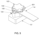
- FIG. 5 is a schematic isometric view illustrating a variant example of the positive locking confirmation mechanism.
- the head portion of the terminal bole further comprises a circular groove, and an insulation safety clip 501 is accommodated within the circular groove. Consequently, even if the positioning bolt is loosened, the positioning bolt is still received within the positioning recess.
- an insulation packing (not shown) is arranged between the positioning bolt and the sensing contact. Due to the insulation packing, the voltage signal is not transmitted between the positioning bolt and the sensing contact.
- FIG. 4 schematically illustrates a wiring configuration of the positive locking confirmation mechanism according to the embodiment of the present invention.
- two battery management units are used to detect the voltage signals from individual electrodes and the locking states of individual electrodes.
- the locking state of a negative terminal 412 of a first battery pack 410 is sensed by a first sensing contact 461 of a first battery management unit 460.
- the locking state of a positive terminal 411 of the first battery pack 410 is sensed by a second sensing contact 462 of the first battery management unit 460.
- the locking state of a positive terminal 421 of a second battery pack 420 is sensed by a third sensing contact 463 of the first battery management unit 460.
- the locking state of a positive terminal 431 of a third battery pack 430 is sensed by a fourth sensing contact 464 of the first battery management unit 460.
- the locking state of a positive terminal 441 of a fourth battery pack 440 is sensed by a fifth sensing contact 465 of the first battery management unit 460.
- the locking state of the negative terminal 412 of the first battery pack 410 is also sensed by a first sensing contact 451 of a second battery management unit 450.
- the locking state of a negative terminal 422 of the second battery pack 420 is sensed by a second sensing contact 452 of the second battery management unit 450.
- the locking state of a negative terminal 432 of the third battery pack 430 is sensed by a third sensing contact 453 of the second battery management unit 450.
- the locking state of a negative terminal 442 of the fourth battery pack 440 is sensed by a fourth sensing contact 454 of the second battery management unit 450.
- the locking state of the positive terminal 441 of the fourth battery pack 440 is also sensed by a fifth sensing contact 451 of the second battery management unit 450.
Abstract
Description
- The present invention relates to a positive locking confirmation mechanism and a positive locking confirmation method for a terminal bolt of a battery pack in a battery box of an electric vehicle, and more particularly to a device of sensing the locking state of the terminal bolt. The positive locking confirmation method is applied to an electric vehicle because a great number of battery packs are connected with each other to provide electric power. The terminal bolts associated with the battery packs are influenced by the vibration of the electric vehicle. The individual battery packs are connected with a battery management unit to provide battery data to a vehicular controlling unit, and thus the influences are monitored by using the positive locking confirmation method.
- Generally, a battery pack of a large electric vehicle comprises several hundreds of batteries. These batteries are connected with each other in parallel or in series. However, if the battery contacts are not securely locked, the batteries of the battery pack are possibly loosened. Especially, when the electric vehicle is driven on a road with a poor condition, the vibration of electric vehicle may accelerate the problem of loosening the battery contacts. If the battery contacts are loosened or poorly contacted during the travelling process of the electric vehicle, the overall power system is possibly shut down or burnt out.
- However, the conventional electrode connecting method cannot indicate whether the electrodes are certainly locked. If the battery pack is suffered from a poor contact problem, the worker cannot immediately realize the damaged site. Under this circumstance, the time period of checking the battery pack is largely increased. Moreover, since the electric vehicle is only powered by the battery pack, the reliability of the battery pack is an important factor influencing performance of the electric vehicle.
- In comparison with gasoline vehicles and diesel vehicles, batteries are the only power sources of the electric vehicles. For acquiring the reliable power source, a feasible and reliable method of detecting the positive locking state of the terminal bolt of the electric vehicle is necessary. However, the method of detecting the positive locking state may use additional sensors or wires in the battery pack. Since the battery pack comprises plural batteries, the additional sensors or wires may increase the labor cost and the assembling complexity. In other words, the conventional method of detecting the positive locking state is not user-friendly.
- Moreover, for connecting the electrodes of the battery pack of the electric vehicle, a voltage sensor (or a current sensor) and a conductive metal are locked on an electrode through a terminal bolt. Under this circumstance, the tasks of replacing the batteries or replacing the voltage sensor will be frequently done. Therefore, there is a need of providing an improved technology to overcome the above drawbacks.
- For overcoming the drawbacks of the electrode of the battery pack of the conventional electric vehicle, the present invention provides a positive locking confirmation mechanism and a positive locking confirmation method.
- The positive locking confirmation mechanism comprises a terminal bolt, a positioning bolt, a conductor, a voltage sensing contact and an electrode. The electrode comprises an electrode thread and a positioning thread. The terminal bolt is used for fixing the conductor on the electrode. The head portion of the terminal bolt comprises plural positioning recesses. During the process of installing the positive locking confirmation mechanism, one positioning recess of the terminal bolt is aligned with the positioning bolt. After the positioning bolt is screwed into the positioning thread through the positioning recess, the voltage sensing contact is fixed on the electrode.
- Moreover, the positioning bolt is used for positioning the terminal bolt in order to confirm the positive locking state of the terminal bolt. Consequently, only when the positioning bolt is removed, the terminal bolt can be detached from the electrode or the location of the terminal bolt can be changed.
- For detecting the locking states of all electrodes of the battery pack, a vehicular controlling unit performs a computing process to judge whether the voltage signal is stable. Once the voltage signal received by a specified voltage sensor is unstable, the vehicular controlling unit can sense the unstable voltage signal. Before the terminal bolt is not in the positive locking state, a task of checking the connection of the electrode corresponding to the voltage sensor needs to be performed. In particular, the vehicular controlling unit issues a warning prompt to notify the user to perform the connection checking task. After the connection checking task, the possibility of detaching the terminal bolt and the conductor from the electrode thread will be minimized. Consequently, the problems of generating electric arc or surge in the electric vehicle will be avoided.
- An object of present invention provides a positive locking confirmation mechanism for increasing the efficacy of assembling the battery contacts and confirming the positive locking state of the battery contact in order to overcome the drawbacks of the conventional technology. Moreover, the positive locking confirmation mechanism can prompt the user to check the locking states of the electrodes of the large battery pack and issue a warning to the driver when the electrodes are possibly loosened.
- Another object of present invention provides a warning means of issuing a warning signal when the electrode is possibly loosened. The warning signal can notify the maintenance worker to check and repair the battery pack.
- Another object of present invention provides a positive locking confirmation mechanism for confirming the locking sate according to a voltage signal of the battery pack that is sensed by a voltage sensor. Consequently, the fabricating cost is reduced.
- Another object of present invention provides a positive locking confirmation mechanism for simplifying the process of assembling or disassembling the battery management unit with/from the battery packs.
- In accordance with an aspect of the present invention, there is provided a positive locking confirmation mechanism for a battery contact of an electric vehicle. The positive locking confirmation mechanism includes an electrode, a terminal bolt, a positioning bolt and a sensing unit. The electrode includes an electrode thread and a positioning thread. The terminal bolt is locked on the electrode, so that a conductor is contacted with the electrode. A head portion of the terminal bolt comprises at least one positioning recess. The positioning bolt is screwed into the positioning thread, so that a sensing contact of a battery management unit is fixed on the electrode. When the positioning bolt is screwed into the positioning thread, the positioning bolt is partially received within the positioning recess. The sensing unit performs a computing process for determining whether the terminal bolt is in a positive locking state according to a result of judging whether a voltage signal from the sensing contact is stable.
- In an embodiment, if the voltage signal is stable, the controlling unit judges that the terminal bolt is in the positive locking state.
- In an embodiment, if the controlling unit senses that the terminal bolt is not in the positive locking state, the controlling unit issues an identification code to a user to prompt the user to check a connection status of the terminal bolt.
- In an embodiment, the positioning bolt is made of an insulation material.
- In an embodiment, a non-conductive coating is formed on a contact area between the sensing contact and the positioning bolt.
- In an embodiment, the controlling unit further includes a gyroscope for sensing a vibration frequency of the electric vehicle. Moreover, the vibration frequency of the electric vehicle is compared with a waveform of the voltage signal.
- In accordance with another aspect of the present invention, there is provided a positive locking confirmation device for an electrode of a battery pack. The positive locking confirmation device includes a terminal bolt, a positioning bolt and an electrode. The positive locking confirmation device performs a computing process to continuously detecting whether a voltage signal from a sensing contact is stable. When the positioning bolt is locked on the electrode and partially received within a positioning recess of the terminal bolt, the terminal bolt is not rotated and the sensing contact is fixed on the electrode.
- The above contents of the present invention will become more readily apparent to those ordinarily skilled in the art after reviewing the following detailed description and accompanying drawings, in which:
-
-
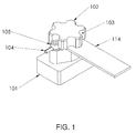
FIG. 1 is a schematic isometric view illustrating a positive locking confirmation mechanism according to an embodiment of the present invention; -
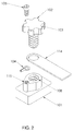
FIG. 2 is a schematic exploded view illustrating a terminal bolt of the positive locking confirmation mechanism according to the embodiment of the present invention; -
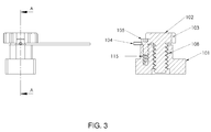
FIG. 3 is a schematic cross-sectional view illustrating a portion of the positive locking confirmation mechanism according to the embodiment of the present invention; -
FIG. 4 schematically illustrates a wiring configuration of the positive locking confirmation mechanism according to the embodiment of the present invention; and -
FIG. 5 is a schematic isometric view illustrating a variant example of the positive locking confirmation mechanism, in which the positive locking confirmation mechanism further comprises a safety clip. - Element numerals in the drawings is illustrated as follows: 101, electrode; 102, terminal bolt; 103, positioning recess; 104, sensing contact; 105, positioning bolt; 108, electrode thread; 114, conductor; 115, positioning thread; 410, first battery pack; 420, second battery pack; 430, third battery pack; 440, fourth battery pack; 450, second battery management unit; 460, first battery management unit; 403, negative terminal connection point; 404, positive terminal connection point; 491, connection wiring of the negative
terminal connection point 403; and 495, connection wiring of the positiveterminal connection point 404. - Hereinafter, a positive locking confirmation mechanism according to an embodiment of the present invention will be illustrated with reference to
FIGS. 1 to 3 . The positive locking confirmation mechanism comprises aterminal bolt 102, apositioning bolt 105, anelectrode 101, aconductor 114 and a voltage sensing contact. Theelectrode 101 comprises anelectrode thread 108 for fixing theconductor 114 and theterminal bolt 102. A head portion of theterminal bolt 102 comprises plural positioning recesses 103 for positioning thepositioning bolt 105 in apositioning thread 115 of theelectrode 101. When thepositioning bolt 105 is screwed into thepositioning thread 115, thesensing contact 104 of a battery management unit is fixed on theelectrode 101. Moreover, thepositioning bolt 105 is received in one of the plural positioning recesses 103 in order to stop rotation of theterminal bolt 102. - A process of installing the positive locking confirmation mechanism will be illustrated as follows. Firstly, the
conductor 114 is placed on theelectrode 101. In addition, a perforation of theconductor 114 is aligned with theelectrode thread 108. Then, theterminal bolt 102 is screwed into theelectrode thread 108, and thus theconductor 114 is fixed between theterminal bolt 102 and theelectrode thread 108. Then, onepositioning recess 103 of theterminal bolt 102 is aligned with thepositioning thread 115. After thepositioning bolt 105 is screwed into thepositioning thread 115, thesensing contact 104 is fixed on theelectrode 101. Consequently, the installation of thepositioning bolt 105 can confirm the positive locking state of theterminal bolt 102. - In other words, the
positioning bolt 105 is used to confirm the positive locking state of theterminal bolt 102. In particular, thepositioning bolt 105 stops the rotation of theterminal bolt 102 in order to confirm the positive locking state of theterminal bolt 102. - The present invention further provides a positive locking confirmation method. In accordance with the positive locking confirmation method, the vehicular controlling unit performs a computing process to detect whether the voltage signal from the sensing contact of the battery management unit is stable.
- In accordance with the positive locking confirmation mechanism of the prevent invention, for rotating the
terminal bolt 102, it is necessary to remove thepositioning bolt 105. Moreover, if thepositioning bolt 105 is loosened because of the vibration of the electric vehicle, it means that the voltage signal is unstable or subjected to fluctuation. According to the unstable voltage signal, the vehicular controlling unit can recognize that thepositioning bolt 105 is loosened. - In case that the sensing contact of the battery management unit is loosened from the terminal bolt of a specified battery pack and is not in the positive locking state, the voltage signal is unstable. Under this circumstance, the vehicular controlling unit accepts a connection check request and indicates the identification code of the battery pack to the user or the maintenance worker. Since the vehicular controlling unit prompts the connection status of the battery pack to the user or the maintenance worker, the problems of generating electric arc or causing power shutdown during the process of driving the electric vehicle will be avoided.
- In accordance with the positive locking confirmation method of the present invention, the vehicular controlling unit continuously performs a computing process to judge whether the current signal or the voltage signal is stable. Preferably, for performing the computing process, a gyroscope is employed for sensing the vibration of the electric vehicle. If the waveform of the voltage signal detected by the vehicular controlling unit matches the vibration frequency of the electric vehicle, the vehicular controlling unit judges that the terminal bolt is no longer in the positive locking state.
- More preferably, the positioning bolt is made of an insulation material. Consequently, the voltage sensor will not receive the voltage signal through the contact area between the sensing contact and the terminal bolt. Since the unstable voltage signal is amplified, the locking state can be detected in a more sensitive manner.
-
FIG. 5 is a schematic isometric view illustrating a variant example of the positive locking confirmation mechanism. The head portion of the terminal bole further comprises a circular groove, and aninsulation safety clip 501 is accommodated within the circular groove. Consequently, even if the positioning bolt is loosened, the positioning bolt is still received within the positioning recess. - In another embodiment, an insulation packing (not shown) is arranged between the positioning bolt and the sensing contact. Due to the insulation packing, the voltage signal is not transmitted between the positioning bolt and the sensing contact.
-
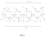
FIG. 4 schematically illustrates a wiring configuration of the positive locking confirmation mechanism according to the embodiment of the present invention. For example, two battery management units are used to detect the voltage signals from individual electrodes and the locking states of individual electrodes. - For example, the locking state of a
negative terminal 412 of afirst battery pack 410 is sensed by afirst sensing contact 461 of a firstbattery management unit 460. The locking state of apositive terminal 411 of thefirst battery pack 410 is sensed by asecond sensing contact 462 of the firstbattery management unit 460. The locking state of apositive terminal 421 of asecond battery pack 420 is sensed by athird sensing contact 463 of the firstbattery management unit 460. The locking state of apositive terminal 431 of athird battery pack 430 is sensed by afourth sensing contact 464 of the firstbattery management unit 460. The locking state of apositive terminal 441 of afourth battery pack 440 is sensed by afifth sensing contact 465 of the firstbattery management unit 460. Moreover, the locking state of thenegative terminal 412 of thefirst battery pack 410 is also sensed by afirst sensing contact 451 of a secondbattery management unit 450. The locking state of anegative terminal 422 of thesecond battery pack 420 is sensed by asecond sensing contact 452 of the secondbattery management unit 450. The locking state of anegative terminal 432 of thethird battery pack 430 is sensed by athird sensing contact 453 of the secondbattery management unit 450. The locking state of anegative terminal 442 of thefourth battery pack 440 is sensed by afourth sensing contact 454 of the secondbattery management unit 450. The locking state of thepositive terminal 441 of thefourth battery pack 440 is also sensed by afifth sensing contact 451 of the secondbattery management unit 450. - In
FIG. 4 , the locking states of the electrodes of four serially-connected battery packs are monitored by two battery management units.
Claims (7)
- A positive locking confirmation mechanism for a battery contact of an electric vehicle, the positive locking confirmation mechanism comprising:an electrode comprising an electrode thread and a positioning thread;a terminal bolt locked on the electrode, so that a conductor is contacted with the electrode, wherein a head portion of the terminal bolt comprises at least one positioning recess;a positioning bolt screwed into the positioning thread, so that a sensing contact of a battery management unit is fixed on the electrode, wherein when the positioning bolt is screwed into the positioning thread, the positioning bolt is partially received within the positioning recess; anda sensing unit, wherein the sensing unit performs a computing process for determining whether the terminal bolt is in a positive locking state according to a result of judging whether a voltage signal from the sensing contact is stable.
- The positive locking confirmation mechanism for the battery contact of the electric vehicle according to claim 1, wherein if the voltage signal is stable, the controlling unit judges that the terminal bolt is in the positive locking state.
- The positive locking confirmation mechanism for the battery contact of the electric vehicle according to claim 2, wherein if the controlling unit senses that the terminal bolt is not in the positive locking state, the controlling unit issues an identification code to a user to prompt the user to check a connection status of the terminal bolt.
- The positive locking confirmation mechanism for the battery contact of the electric vehicle according to claim 1, wherein the positioning bolt is made of an insulation material.
- The positive locking confirmation mechanism for the battery contact of the electric vehicle according to claim 1, wherein a non-conductive coating is formed on a contact area between the sensing contact and the positioning bolt.
- The positive locking confirmation mechanism for the battery contact of the electric vehicle according to claim 1, wherein the controlling unit further comprises a gyroscope for sensing a vibration frequency of the electric vehicle, wherein the vibration frequency of the electric vehicle is compared with a waveform of the voltage signal.
- A positive locking confirmation device for an electrode of a battery pack, the positive locking confirmation device comprising a terminal bolt, a positioning bolt and an electrode, wherein the positive locking confirmation device performs a computing process to continuously detecting whether a voltage signal from a sensing contact is stable, wherein when the positioning bolt is locked on the electrode and partially received within a positioning recess of the terminal bolt, the terminal bolt is not rotated and the sensing contact is fixed on the electrode.
Applications Claiming Priority (1)
| Application Number | Priority Date | Filing Date | Title |
|---|---|---|---|
| PCT/CN2013/085317 WO2015054844A1 (en) | 2013-10-16 | 2013-10-16 | Mechanism for confirming locked state of electrode contact of electric vehicle and apparatus for confirming locked state of battery module electrode |
Publications (2)
| Publication Number | Publication Date |
|---|---|
| EP3059779A1 true EP3059779A1 (en) | 2016-08-24 |
| EP3059779A4 EP3059779A4 (en) | 2017-03-15 |
Family
ID=52827549
Family Applications (1)
| Application Number | Title | Priority Date | Filing Date |
|---|---|---|---|
| EP13895607.3A Withdrawn EP3059779A4 (en) | 2013-10-16 | 2013-10-16 | Mechanism for confirming locked state of electrode contact of electric vehicle and apparatus for confirming locked state of battery module electrode |
Country Status (7)
| Country | Link |
|---|---|
| US (1) | US20160240833A1 (en) |
| EP (1) | EP3059779A4 (en) |
| JP (1) | JP6262338B2 (en) |
| KR (1) | KR20160071425A (en) |
| CN (1) | CN105637671B (en) |
| CA (1) | CA2927503A1 (en) |
| WO (1) | WO2015054844A1 (en) |
Cited By (1)
| Publication number | Priority date | Publication date | Assignee | Title |
|---|---|---|---|---|
| FR3062956A1 (en) * | 2017-02-15 | 2018-08-17 | Aptiv Technologies Limited | FEMALE ELECTRICAL CONNECTION ASSEMBLY |
Families Citing this family (10)
| Publication number | Priority date | Publication date | Assignee | Title |
|---|---|---|---|---|
| US11177543B2 (en) * | 2016-07-28 | 2021-11-16 | ETAK Systems, LLC | Battery installation with security screws for theft deterrence in cell site shelters and the like |
| FR3053794B1 (en) * | 2016-07-11 | 2019-12-20 | Renault S.A.S. | DEVICE FOR MEASURING A CURRENT WITH VERTICAL CLAMPING ON A BATTERY TERMINAL |
| US11101517B2 (en) * | 2016-07-28 | 2021-08-24 | ETAK Systems, LLC | Battery security systems and methods for telecommunication sites |
| KR102158363B1 (en) * | 2017-04-07 | 2020-09-21 | 주식회사 엘지화학 | Battery module with improved connecting structure between electrode leads and manufacturing method thereof |
| CN108297841B (en) * | 2018-01-30 | 2019-10-18 | 湖南工学院 | Electric automobile chassis battery change system |
| CN108297842B (en) * | 2018-01-30 | 2019-08-30 | 湖南工学院 | Automobile chassis battery modules and change electric system |
| JP6840104B2 (en) * | 2018-04-18 | 2021-03-10 | 本田技研工業株式会社 | Battery charger |
| JP6713524B2 (en) * | 2018-12-17 | 2020-06-24 | 本田技研工業株式会社 | Battery unit |
| KR20200127638A (en) | 2019-05-03 | 2020-11-11 | 주식회사 엘지화학 | Apparatus and method for diagnosing battery cell |
| CN111703330B (en) * | 2020-06-12 | 2022-04-19 | 北京新能源汽车股份有限公司 | Battery replacement control system, electric automobile and battery replacement control method |
Family Cites Families (15)
| Publication number | Priority date | Publication date | Assignee | Title |
|---|---|---|---|---|
| JP3365602B2 (en) * | 1996-05-09 | 2003-01-14 | トヨタ自動車株式会社 | Control method of battery output of electric vehicle and terminal connection structure of battery used for the method |
| JP3786087B2 (en) * | 2002-12-26 | 2006-06-14 | ふそうエンジニアリング株式会社 | Battery terminal |
| JP2006085945A (en) * | 2004-09-14 | 2006-03-30 | Denso Corp | Mounting structure of current sensor |
| CN101232082B (en) * | 2007-01-25 | 2010-05-26 | 深圳华粤宝电池有限公司 | Battery cover plate with new type structure and secondary battery thereof |
| JP2008241421A (en) * | 2007-03-27 | 2008-10-09 | Toyota Motor Corp | Detection device for detecting state of connection member and storage battery mechanism provided with the detection device |
| CN201344916Y (en) * | 2008-11-21 | 2009-11-11 | 比亚迪股份有限公司 | Three-electrode system testing device |
| JP4696291B2 (en) * | 2009-06-04 | 2011-06-08 | 三菱自動車工業株式会社 | Secondary battery abnormality detection device |
| KR20110133257A (en) * | 2010-06-04 | 2011-12-12 | 에스비리모티브 주식회사 | Rechargeable battery |
| KR101310733B1 (en) * | 2011-01-07 | 2013-09-24 | 주식회사 엘지화학 | Apparatus and method for managing battery pack |
| CN202189856U (en) * | 2011-08-08 | 2012-04-11 | 深圳市沃特玛电池有限公司 | Connecting structure of battery pack pole piece |
| KR101669116B1 (en) * | 2011-12-01 | 2016-10-26 | 삼성에스디아이 주식회사 | Battery module having sensing member |
| CN202507950U (en) * | 2012-03-28 | 2012-10-31 | 力帆实业(集团)股份有限公司 | High-voltage connection management system of battery pack |
| KR101280292B1 (en) * | 2012-07-02 | 2013-07-01 | 주식회사 대일프로텍 | Apparatus for error detection in receive and change electricity equipment using multi-sensor |
| JP2014229351A (en) * | 2013-05-17 | 2014-12-08 | 株式会社豊田自動織機 | Battery module |
| JP2015056266A (en) * | 2013-09-11 | 2015-03-23 | 三菱重工業株式会社 | Fastening device having fasteners, fastener loosening detection device, and battery module equipped with fastening device |
-
2013
- 2013-10-16 US US15/029,856 patent/US20160240833A1/en not_active Abandoned
- 2013-10-16 CA CA2927503A patent/CA2927503A1/en not_active Abandoned
- 2013-10-16 CN CN201380080289.6A patent/CN105637671B/en not_active Expired - Fee Related
- 2013-10-16 WO PCT/CN2013/085317 patent/WO2015054844A1/en active Application Filing
- 2013-10-16 JP JP2016523964A patent/JP6262338B2/en not_active Expired - Fee Related
- 2013-10-16 EP EP13895607.3A patent/EP3059779A4/en not_active Withdrawn
- 2013-10-16 KR KR1020167012385A patent/KR20160071425A/en active IP Right Grant
Cited By (1)
| Publication number | Priority date | Publication date | Assignee | Title |
|---|---|---|---|---|
| FR3062956A1 (en) * | 2017-02-15 | 2018-08-17 | Aptiv Technologies Limited | FEMALE ELECTRICAL CONNECTION ASSEMBLY |
Also Published As
| Publication number | Publication date |
|---|---|
| CN105637671A (en) | 2016-06-01 |
| CA2927503A1 (en) | 2015-04-23 |
| WO2015054844A1 (en) | 2015-04-23 |
| EP3059779A4 (en) | 2017-03-15 |
| JP6262338B2 (en) | 2018-01-17 |
| CN105637671B (en) | 2018-01-19 |
| KR20160071425A (en) | 2016-06-21 |
| US20160240833A1 (en) | 2016-08-18 |
| JP2016533618A (en) | 2016-10-27 |
Similar Documents
| Publication | Publication Date | Title |
|---|---|---|
| EP3059779A1 (en) | Mechanism for confirming locked state of electrode contact of electric vehicle and apparatus for confirming locked state of battery module electrode | |
| US9559464B2 (en) | Positive locking confirmation mechanism for battery contact of electric vehicle | |
| CN108604516B (en) | Relay device | |
| JP2010282816A (en) | Secondary-battery abnormality detector | |
| US20160033581A1 (en) | Abnormality diagnosis device | |
| CN103887568A (en) | Battery Management System And Integrated Battery Management Device | |
| KR100342838B1 (en) | Dsrc on-vehicle device | |
| US7459911B2 (en) | Method for detecting the connection between the energy storage mechanism and the electrical system of a vehicle | |
| US10840562B2 (en) | Energy storage system, monitoring unit for energy storage device, and method of monitoring energy storage device | |
| CN104395135A (en) | Power storage system and control device of power storage device | |
| CN104953195B (en) | Method and system for evaluating integrity of vehicle components based on resistance | |
| CN111993891B (en) | Electric vehicle data storage device and control method and monitoring system thereof | |
| CN112166532B (en) | Interlock system | |
| CN113631938B (en) | Method and system for detecting connection failure of parallel battery cells | |
| EP3059797B1 (en) | Detection apparatus for detecting locked states of multiple electrodes by using battery sensor | |
| JP2015058846A (en) | Diagnostic system | |
| US20220048392A1 (en) | Fire protection device for an at least partially electrically operated motor vehicle, and fire sensor | |
| CN105429196A (en) | Monitoring in protecting conductor during charging | |
| TWI479169B (en) | A Positive Locking Confirmation Apparatus of a Terminal Bolt utilizing a Voltage Sensor of a Battery Management Unit | |
| TW201517351A (en) | A positive locking confirmation apparatus and a method for preventing loose connection of battery terminal for electric vehicle | |
| US20220128630A1 (en) | Measurement system and method for determining a status of a power system in a vehicle using the measurement system | |
| US20150258896A1 (en) | Electric Vehicle Control Device | |
| KR100569910B1 (en) | Battery ground alarm device |
Legal Events
| Date | Code | Title | Description |
|---|---|---|---|
| PUAI | Public reference made under article 153(3) epc to a published international application that has entered the european phase |
Free format text: ORIGINAL CODE: 0009012 |
|
| 17P | Request for examination filed |
Effective date: 20160517 |
|
| AK | Designated contracting states |
Kind code of ref document: A1 Designated state(s): AL AT BE BG CH CY CZ DE DK EE ES FI FR GB GR HR HU IE IS IT LI LT LU LV MC MK MT NL NO PL PT RO RS SE SI SK SM TR |
|
| AX | Request for extension of the european patent |
Extension state: BA ME |
|
| RAP1 | Party data changed (applicant data changed or rights of an application transferred) |
Owner name: ALEEES ECO ARK (CAYMAN) CO. LTD. |
|
| DAX | Request for extension of the european patent (deleted) | ||
| A4 | Supplementary search report drawn up and despatched |
Effective date: 20170210 |
|
| RIC1 | Information provided on ipc code assigned before grant |
Ipc: B60L 11/18 20060101ALI20170206BHEP Ipc: B60L 3/00 20060101ALI20170206BHEP Ipc: H01M 2/10 20060101ALN20170206BHEP Ipc: H01M 2/30 20060101ALI20170206BHEP Ipc: H01M 10/48 20060101AFI20170206BHEP Ipc: H01M 2/20 20060101ALN20170206BHEP |
|
| 17Q | First examination report despatched |
Effective date: 20170915 |
|
| RIC1 | Information provided on ipc code assigned before grant |
Ipc: H01M 2/30 20060101ALI20171129BHEP Ipc: H01R 4/34 20060101ALN20171129BHEP Ipc: H01M 2/20 20060101ALN20171129BHEP Ipc: B60L 11/18 20060101ALI20171129BHEP Ipc: H01M 10/48 20060101AFI20171129BHEP Ipc: H01R 13/641 20060101ALN20171129BHEP Ipc: H01M 2/10 20060101ALN20171129BHEP Ipc: B60L 3/00 20060101ALI20171129BHEP |
|
| GRAP | Despatch of communication of intention to grant a patent |
Free format text: ORIGINAL CODE: EPIDOSNIGR1 |
|
| INTG | Intention to grant announced |
Effective date: 20180105 |
|
| STAA | Information on the status of an ep patent application or granted ep patent |
Free format text: STATUS: THE APPLICATION IS DEEMED TO BE WITHDRAWN |
|
| 18D | Application deemed to be withdrawn |
Effective date: 20180516 |