EP3059596A1 - Electric current measurement apparatus and electric current measurement method - Google Patents
Electric current measurement apparatus and electric current measurement method Download PDFInfo
- Publication number
- EP3059596A1 EP3059596A1 EP14853530.5A EP14853530A EP3059596A1 EP 3059596 A1 EP3059596 A1 EP 3059596A1 EP 14853530 A EP14853530 A EP 14853530A EP 3059596 A1 EP3059596 A1 EP 3059596A1
- Authority
- EP
- European Patent Office
- Prior art keywords
- current
- magnetic element
- frequency
- voltage
- electric current
- Prior art date
- Legal status (The legal status is an assumption and is not a legal conclusion. Google has not performed a legal analysis and makes no representation as to the accuracy of the status listed.)
- Granted
Links
- 238000005259 measurement Methods 0.000 title claims abstract description 218
- 238000000691 measurement method Methods 0.000 title claims description 7
- 238000012937 correction Methods 0.000 claims description 18
- 230000007246 mechanism Effects 0.000 claims description 7
- 238000000034 method Methods 0.000 description 26
- 230000008569 process Effects 0.000 description 26
- 230000000694 effects Effects 0.000 description 18
- 238000010586 diagram Methods 0.000 description 17
- 230000008859 change Effects 0.000 description 9
- 238000001228 spectrum Methods 0.000 description 7
- 230000005415 magnetization Effects 0.000 description 6
- 238000012805 post-processing Methods 0.000 description 6
- 238000007781 pre-processing Methods 0.000 description 6
- 238000013459 approach Methods 0.000 description 5
- 239000004020 conductor Substances 0.000 description 5
- 230000007423 decrease Effects 0.000 description 4
- 230000009467 reduction Effects 0.000 description 4
- 230000005355 Hall effect Effects 0.000 description 3
- 238000006243 chemical reaction Methods 0.000 description 3
- 230000003247 decreasing effect Effects 0.000 description 3
- 238000005516 engineering process Methods 0.000 description 3
- 230000006870 function Effects 0.000 description 3
- 230000035945 sensitivity Effects 0.000 description 3
- NAWXUBYGYWOOIX-SFHVURJKSA-N (2s)-2-[[4-[2-(2,4-diaminoquinazolin-6-yl)ethyl]benzoyl]amino]-4-methylidenepentanedioic acid Chemical compound C1=CC2=NC(N)=NC(N)=C2C=C1CCC1=CC=C(C(=O)N[C@@H](CC(=C)C(O)=O)C(O)=O)C=C1 NAWXUBYGYWOOIX-SFHVURJKSA-N 0.000 description 2
- 238000004458 analytical method Methods 0.000 description 2
- 239000000463 material Substances 0.000 description 2
- 238000010248 power generation Methods 0.000 description 2
- 238000005549 size reduction Methods 0.000 description 2
- 239000000758 substrate Substances 0.000 description 2
- RYGMFSIKBFXOCR-UHFFFAOYSA-N Copper Chemical compound [Cu] RYGMFSIKBFXOCR-UHFFFAOYSA-N 0.000 description 1
- 230000003321 amplification Effects 0.000 description 1
- 230000005540 biological transmission Effects 0.000 description 1
- 239000011248 coating agent Substances 0.000 description 1
- 238000000576 coating method Methods 0.000 description 1
- 229910052802 copper Inorganic materials 0.000 description 1
- 239000010949 copper Substances 0.000 description 1
- 238000001514 detection method Methods 0.000 description 1
- 238000011161 development Methods 0.000 description 1
- 230000002500 effect on skin Effects 0.000 description 1
- 238000005265 energy consumption Methods 0.000 description 1
- 230000007613 environmental effect Effects 0.000 description 1
- 239000000446 fuel Substances 0.000 description 1
- 238000009413 insulation Methods 0.000 description 1
- 239000000696 magnetic material Substances 0.000 description 1
- 238000003199 nucleic acid amplification method Methods 0.000 description 1
- 238000000206 photolithography Methods 0.000 description 1
- 238000012545 processing Methods 0.000 description 1
- 239000011347 resin Substances 0.000 description 1
- 229920005989 resin Polymers 0.000 description 1
- 229920006395 saturated elastomer Polymers 0.000 description 1
- 239000004065 semiconductor Substances 0.000 description 1
- 230000001360 synchronised effect Effects 0.000 description 1
Images


Classifications
-
- G—PHYSICS
- G01—MEASURING; TESTING
- G01R—MEASURING ELECTRIC VARIABLES; MEASURING MAGNETIC VARIABLES
- G01R15/00—Details of measuring arrangements of the types provided for in groups G01R17/00 - G01R29/00, G01R33/00 - G01R33/26 or G01R35/00
- G01R15/14—Adaptations providing voltage or current isolation, e.g. for high-voltage or high-current networks
- G01R15/20—Adaptations providing voltage or current isolation, e.g. for high-voltage or high-current networks using galvano-magnetic devices, e.g. Hall-effect devices, i.e. measuring a magnetic field via the interaction between a current and a magnetic field, e.g. magneto resistive or Hall effect devices
- G01R15/207—Constructional details independent of the type of device used
-
- G—PHYSICS
- G01—MEASURING; TESTING
- G01R—MEASURING ELECTRIC VARIABLES; MEASURING MAGNETIC VARIABLES
- G01R15/00—Details of measuring arrangements of the types provided for in groups G01R17/00 - G01R29/00, G01R33/00 - G01R33/26 or G01R35/00
- G01R15/14—Adaptations providing voltage or current isolation, e.g. for high-voltage or high-current networks
- G01R15/20—Adaptations providing voltage or current isolation, e.g. for high-voltage or high-current networks using galvano-magnetic devices, e.g. Hall-effect devices, i.e. measuring a magnetic field via the interaction between a current and a magnetic field, e.g. magneto resistive or Hall effect devices
- G01R15/205—Adaptations providing voltage or current isolation, e.g. for high-voltage or high-current networks using galvano-magnetic devices, e.g. Hall-effect devices, i.e. measuring a magnetic field via the interaction between a current and a magnetic field, e.g. magneto resistive or Hall effect devices using magneto-resistance devices, e.g. field plates
-
- G—PHYSICS
- G01—MEASURING; TESTING
- G01R—MEASURING ELECTRIC VARIABLES; MEASURING MAGNETIC VARIABLES
- G01R19/00—Arrangements for measuring currents or voltages or for indicating presence or sign thereof
- G01R19/0092—Arrangements for measuring currents or voltages or for indicating presence or sign thereof measuring current only
-
- G—PHYSICS
- G01—MEASURING; TESTING
- G01R—MEASURING ELECTRIC VARIABLES; MEASURING MAGNETIC VARIABLES
- G01R21/00—Arrangements for measuring electric power or power factor
- G01R21/08—Arrangements for measuring electric power or power factor by using galvanomagnetic-effect devices, e.g. Hall-effect devices
Definitions
- the present invention relates to an electric current measurement apparatus and an electric current measurement method that can measure a spectrum of a current flowing in a measurement target circuit.
- a large amount of harmonic current is generated in an inverter to convert direct-current power generated by an inverter power supply or a solar battery incorporated in an air conditioner, an electric vehicle (EV), and a hybrid electric vehicle (HEV) into alternating-current power of a commercial frequency.
- EV electric vehicle
- HEV hybrid electric vehicle
- the current is converted into a voltage by an ammeter (also referred to as "CT” : Current Transformer) and a shunt resistor, and the measurement using analysis (Fourier analysis) by a computer or a filter function by an electronic circuit is then performed.
- CT Current Transformer
- analysis Frier analysis
- an electric current measurement apparatus using a magnetic element is known as an electric current measurement apparatus that does not use the shunt resistor and is relatively cheap.
- the "magnetic element” is an element that changes an electrical characteristic by a magnetic field from the outside of the element. Therefore, a Hall element using a semiconductor is also handled as the magnetic element.
- the magnetic element detects a magnetic field generated by a current. Therefore, current measurement using the magnetic element becomes technology called magnetic field detection widely.
- a clamp-type ammeter is representatively used. This is inserted into a magnetic circuit in which a conductor to which a current flows is configured using a magnetic material and a magnetic field generated by the current is detected by the magnetic element (Patent Literature 1).
- Patent Literature 2 the invention in which power consumption in a measurement target circuit is measured by the magnetic element is reported (Patent Literature 2).
- Patent Literature 3 a magnetic field measurement apparatus using a magnetic impedance effect is reported (Patent Literature 3).
- the magnetic impedance effect is an effect in which, when an alternating current is flown to the magnetic element and a flow of the current is unevenly distributed on only a surface of the magnetic element by a skin effect, impedance of the magnetic element changes at high sensitivity with respect to an external magnetic field.
- the clamp-type ammeter is normally used for measurement of a direct-current magnetic field and can display only a maximum magnetic field or an effective value when a current flowing in a measurement target circuit is an alternating current.
- a power meter using the magnetic element needs to be incorporated into the measurement target circuit. That is, a current of the measurement target circuit is used. However, it is not easy to measure a current that already flows to a certain circuit.
- the magnetic field measurement apparatus using the magnetic impedance effect has high sensitivity, but measurement of the alternating current flowing in the measurement target circuit is not reported.
- an electric current measurement apparatus for measuring a current flowing in a conducting wire of a measurement target circuit includes:
- an electric current measurement method includes:
- An electric current measurement apparatus can acquire a spectrum of a current flowing in a measurement target circuit with a simple configuration such as a magnetic element, a drive current generator, and a voltage meter.
- the measurement principle approximates to heterodyne and super heterodyne.
- an exclusively used circuit to perform the heterodyne is not necessary.
- the magnetic element may execute an operation.
- measurement can be performed with precision of a band of a cutoff frequency of a low-pass filter.
- the measurement can be performed with precision of a band of several Hz, with respect to a frequency of MHz order. That is, when a high frequency current is measured, a current of a conducting wire of the measurement target circuit can be detected with a very high Q value.
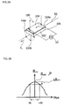
- FIG. 1 illustrates a configuration of an electric current measurement apparatus 1 according to this embodiment.
- a measurement target circuit 90 includes a power supply (referred to as "PS") 91, a load 93, and a conducting wire 92 to connect the power supply 91 and the load 93.
- the electric current measurement apparatus 1 includes a sensor unit 10, a current generator (referred to as “CG”) 12, a low-pass filter (referred to as “LPF”) 16, and a voltage meter (referred to as "VM”) 18.
- CG current generator
- LPF low-pass filter
- VM voltage meter
- a controller (Micro Processor Unit, described as “MPU") 20 to execute whole control, a memory (referred to as “MM”) 22, an A/D converter (referred to as “A/D”) 24, and an input/output device (referred to as “I/O") 26 may be further provided.
- a magnetic element 11 is disposed in the sensor unit 10.
- the magnetic element 11 may be a magnetoresistive element or a Hall element. In this embodiment, the case in which the magnetic element 11 is the magnetoresistive element is described.
- the magnetic element 11 is fixed to an inside of a casing 10a.
- a holder 10b (although not illustrated in Fig. 1 , it is described in detail with reference to Fig. 2 ) to fix a part (conducting wire 92) of the measurement target circuit 90 is disposed.
- the conducting wire 92 in which a current flows is not clamped in a magnetic circuit, it is necessary to fix a distance between the magnetic element 11 and the conducting wire 92 (current).
- Fig. 2 illustrates an example of the sensor unit 10.
- the sensor unit 10 includes the casing 10a formed of a nonmagnetic material to hold the magnetic element 11 (not illustrated in Fig. 2 ) inside and the holder 10b provided on atop surface thereof.
- current terminals 10c to connect the internal magnetic element 11 and the current generator 12 and voltage terminals 10d to measure a voltage of the magnetic element 11 are provided in the casing 10a.
- the holder 10b can fix a distance between the magnetic element 11 and the conducting wire 92. If the holder 10b is formed of a nonmagnetic material, a shape is not limited in particular. The shape of the holder 10b may be changed according to a thickness of the conducting wire 92 or a thickness of coating of the conducting wire 92. The sensor unit may be replaced with the sensor unit 10 having the holder 10b with a different shape for each thickness of the conducting wire 92.
- the conducting wire 92 is preferably fixed to a portion on or a portion below the magnetic element 11 in a thickness direction thereof. This is because a magnetoresistive effect appears to an external magnetic field of an in-plane direction with respect to a current flowing in the magnetic element 11.
- the holder 10b is preferably fixed to a position that is parallel to the current flowing in the magnetic element 11 and is adjacent to the magnetic element 11. This is because a Hall effect appears to an external magnetic field from a direction vertical to the in-plane direction, with respect to the current flowing in the magnetic element 11. According to a difference of kinds of the magnetoresistive element and the hall element, an appropriate relation of a portion to detect a voltage of the magnetic element 11 and the conducting wire 92 may be different from the above description.
- the holder 10b may be formed to fix a position relation between the magnetic element 11 and the conducting wire 92.
- a pair of drive current terminals 11a for generating the current in the magnetic element 11 and a pair of measurement voltage terminals 11b for measuring the voltage of the magnetic element 11 are provided in the magnetic element 11.
- the drive current terminal 11a is connected to the current terminal 10c provided in the casing 10a of the sensor unit 10 and the measurement voltage terminal 11b is connected to the voltage terminal 10d of the casing 10a.
- the drive current terminal 11a and the measurement voltage terminal 11b may be commonly used or may be in a position relation of a right angle.
- the drive current terminal 11a and the measurement voltage terminal 11b are often commonly used.
- the drive current terminal 11a and the measurement voltage terminal 11b are often in the position relation of the right angle.
- the current generator 12 (CG) is a current source to supply an alternating current.
- the current generator 12 is connected to the current terminal 10c of the sensor unit 10. Because the current terminal 10c of the sensor unit 10 and the drive current terminal 11a of the magnetic element 11 are connected to each other, it may be said that the current generator 12 is connected to the drive current terminal 11a.
- a frequency is preferably variable. This is because the electric current measurement apparatus 1 measures a current of a frequency almost equal to a frequency generated by the current generator 12 among currents flowing in the conducting wire 92.
- a plurality of AC current generators 12 may be provided and may be sequentially switched. Such a configuration will be illustrated in a second embodiment. When a frequency to be measured is previously known, it is not excluded that the current generator 12 supplies a current of only the frequency.
- the current generator 12 may be a constant voltage source as well as a constant current source.
- a frequency characteristic of the current flowing in the magnetic element 11 can be known by previously measuring the frequency characteristic. Therefore, measurement sensitivity depending on an amount of the current flowing in the magnetic element 11 can be corrected thereafter.
- the constant voltage source is used as the current generator 12
- impedance of the magnetic element 11 is changed according to a frequency. For this reason, an amount of flowing current is different according to the frequency. Therefore, preferably, an amount of flowing current is previously measured for each frequency and a table or a correction value is prepared.
- the voltage meter 18 is connected to the measurement voltage terminal 11b of the magnetic element 11 via the voltage terminal 10d provided in the casing 10a. Because the measurement voltage terminal 11b and the voltage terminal 10d are connected to each other, it may be said that the voltage meter 18 is connected to the measurement voltage terminal 11b.
- the voltage meter 18 may have an appropriate amplifier inside and a direct-current voltage may be measured. This is because the voltage meter 18 measures only a voltage between both ends of the magnetic element 11 through the low-pass filter 16.
- the low-pass filter 16 (referred to as the LPF) is disposed between the magnetic element 11 and the voltage meter 18.
- a cutoff frequency fc of the low-pass filter 16 may be fixed. More preferably, an active filter has an attenuation rate changed by an external control signal. In addition, in the case of a configuration in which the cutoff frequency fc can be changed, because a measurement bandwidth at the time of measuring a current can be changed, this is preferable.
- a one-chip computer is suitable for the controller 20.
- the controller 20 is connected to the current generator 12 and the voltage meter 18.
- the controller 20 may be connected to the low-pass filter 16.
- the controller 20 can transmit an instruction signal Cc to the current generator 12 to control timing for generating current and the magnitude and the frequency of the generated current.
- the cutoff frequency fc of the low-pass filter 16 can be changed by an instruction signal Cf.
- a measurement signal Sv from the voltage meter 18 can be received.
- the input/output device 26 capable of operated by an operator and the memory 22 may be connected to the controller 20. This is because the controller performs start of measurement, progress of the measurement, display of measurement data, and storage of the measurement data.
- the controller 20 can exchange an output signal Cio and an input signal Sio with the input/output device 26.
- the measurement data is included in the output signal Cio and an instruction signal for the controller 20 is included in the input signal Sio.
- the A/D converter 24 may be disposed between the controller 20 and the voltage meter 18. This is because an output of the voltage meter 18 may be an analog signal.
- the magnetic element 11 has a property that a current flow is changed by a magnetic field applied from the outside.
- the change of the current flow may be observed by a voltage of a current direction and may be observed by a voltage of a direction perpendicular to the current direction, with respect to the element.
- a representative example of the former is the magnetoresistive effect and a representative example of the latter is the Hall effect.
- Figs. 3A and 3B are graphs illustrating the magnetoresistive element and the magnetoresistive effect.
- a magnetic film 104 is formed on a strip-shaped substrate 102. A direction from one end 104a of a strip shape to the other end 104b is called a longitudinal direction.
- the magnetic film 104 is preferably formed such that a magnetization easy axis is induced in the longitudinal direction.
- a current 105 flows in the longitudinal direction.
- the magnetoresistive element is disposed such that the longitudinal direction is matched with a direction in which a current I 1 of the conducting wire 92 of the measurement target circuit flows.
- Fig. 3A an aspect where the conducting wire 92 of the measurement target circuit is disposed below the substrate 102 is illustrated.
- the external magnetic field Hex inclines magnetization of the magnetic film 104 of the longitudinal direction from the magnetization easy axis. That is, the direction of the current 105 flowing in the magnetic film 104 and the direction of the magnetization change. At this time, the magnetoresistive effect is generated and electrical resistance of the magnetic film 104 changes.
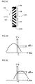
- Fig. 3B illustrates a graph illustrating a general magnetoresistive effect.
- a horizontal axis shows an external magnetic field Hex (A/m) applied from a direction perpendicular to the longitudinal direction of the magnetic film 104 and a vertical axis shows electrical resistance (hereinafter, simply referred to as a "resistance value") Rmr (Q) of the longitudinal direction of the magnetic film 104.
- the electrical resistance of the magnetic film 104 when the external magnetic field Hex is not applied is set as Rm0. If the external magnetic field Hex is applied to the magnetoresistive element 100, the electrical resistance is decreased by ⁇ Rmr.
- the decrease in the electrical resistance Rmr does not depend on the direction (positive/negative direction) of the external magnetic field Hex. That is, the magnetoresistive effect has a characteristic of an even function with respect to the external magnetic field Hex.
- the operation point P means a point when the external magnetic field Hex is zero on a curve showing the magnetoresistive effect and at this time, a value of the electrical resistance is Rm0.
- Figs. 4A and 4B illustrate an improved magnetoresistive element.
- Fig. 4C illustrates a graph corresponding to Fig. 3B .
- Fig. 4C illustrates a state in which the operation point P is moved to a point shown by a reference numeral 107 by previously applying a bias magnetic field Hbias to the magnetoresistive element.
- the bias magnetic field Hbias may be applied from the direction perpendicular to the longitudinal direction of the strip-shaped magnetoresistive element.
- Fig. 4B illustrates a magnetoresistive element 112.
- the magnetoresistive element 112 is obtained by forming an inclined continuous pattern 113 (pattern of abarberpole type) on a surface of the magnetic film 104 with a conductor such as copper. Because a current I 2 flowing between the continuous pattern 113 of the inclined conductor flows in a shortest distance of the inclined pattern, the current I 2 flows in an inclined direction when viewed from the longitudinal direction (direction where the magnetization easy axis is formed). Even though the bias magnetic field Hbias is not used, when the external magnetic field Hex is zero, the directions of the current and the magnetization are inclined in the magnetoresistive element 112. For this reason, the magnetoresistive element 112 has an effect that the bias magnetic field Hbias is applied. That is, as illustrated in Fig. 4C , the operation point P is set to the inclined portion of the characteristic curve.
- bias mechanism means not only providing a magnet for bias, but also what has an effect having an apparent bias magnetic field Hbias due to a pattern configuration of the conductor as illustrated in Fig. 4B .
- Fig. 5A illustrates amagnetoresistiveelement 115 in which two patterns of a barber pole type are disposed to face each other.
- an upper magnetoresistive element is represented by a reference numeral 116 and a lower magnetoresistive element is represented by a reference numeral 117.
- a graph showing a magnetoresistive effect of the magnetoresistive element 116 is illustrated in Fig. 5B and a graph showing a magnetoresistive effect of the magnetoresistive element 117 is illustrated in Fig. 5C .
- a center portion 115c is connected to a ground (center tap) and the current I 2 flows from one end 115a to the other end 115b. At this time, an inclined direction of the current I 2 depends on inclined patterns.
- the electrical resistance decreases by 2 ⁇ Rmr between the terminals 115a and 115b. That is, an output of a double (+6 dB) of each element can be obtained in both ends of the magnetoresistive element 115.
- the magnetic element 11 of Fig. 1 exemplifies this type. That is, the magnetic element 11 has the center tap that is connected to a ground.
- Figs. 6A and 6B illustrate a Hall element 120 and a characteristic thereof.
- a Hall effect appears when a current flowing through the Hall element 120 is unevenly distributed in the element due to a magnetic field applied from a direction perpendicular to a flow of the current and a potential difference is generated.
- the current I 2 flows from one end 120a to the other end 120b of the Hall element 120.
- the conducting wire 92 of the measurement target circuit is disposed to be adjacent to the Hall element 120.
- the external magnetic field Hex generated by the current I 1 flowing in the conducting wire 92 passes from a bottom surface 120d to a top surface 120u of the Hall element 120.
- the flowing current I 2 receives force and is distributed in a width direction 120f of the Hall element 120.
- a potential difference is generated in the width direction (120e and 120f) of the Hall element 120.
- the potential difference is called a Hall voltage
- Fig. 6B illustrates a graph showing a characteristic thereof.
- a horizontal axis shows the external magnetic field Hex.
- a vertical axis shows the Hall voltage VH.
- the Hall element 120 when the external magnetic field Hex has the predetermined magnitude, a substantially linear portion 122 is observed. If the external magnetic field Hex is more than a predetermined value, a portion 123 in which the Hall voltage VH is saturated is observed.
- An embodiment using the Hall element 120 is illustrated in a second embodiment.
- ⁇ is a proportional constant.
- the magnetic element 11 receives the magnetic field H generated by the conducting wire 92 and the resistance value Rmr is changed by the magnetoresistive effect.
- ⁇ Rmr ⁇ H
- the current I 1 flowing in the measurement target circuit 90 and the current I 2 flowing in the magnetic element 11 are represented by formulae (6) and (7), respectively.
- I 1 I 1 sin 2 ⁇ f 1 t
- I 2 I 2 sin 2 ⁇ f 2 t
- f 1 and f 2 show frequencies and t shows a time.
- n shows a circular constant.
- a voltage Vmr having two frequency components (f 1 - f 2 and f 1 + f 2 ) of ⁇ I 1 I 2 cos2 ⁇ (f 1 - f 2 )t and ⁇ I 1 I 2 cos2 ⁇ (f 1 + f 2 )t is observed in both ends of the magnetic element 11.
- ⁇ is a proportional constant.
- Vs ⁇ I 1 I 2 cos 2 ⁇ f 1 ⁇ f 2 t
- Vs ⁇ I 1 I 2
- the current I 2 of the frequency f 2 flowing in the conducting wire 92 can be observed as a current spectrum of a measurement bandwidth 2fc (when a complex filter is used, a bandwidth is fc).
- a bandwidth is fc.
- Figs. 7A to 7D illustrate this relation.
- a horizontal axis shows a frequency f and a vertical axis shows an output Vs of the voltage meter 18.
- a frequency of the current I 1 flowing in the measurement target circuit 90 is set as f 1 .
- the current I 2 of the frequency f 2 flows from the current generator 12 of the electric current measurement apparatus 1 and the current I 1 of the frequency f 1 flows in the conducting wire 92 of the measurement target circuit 90.
- signals of f 1 - f 2 and f 1 + f 2 are generated as represented by the formula (8).
- the frequency f 2 of the current generator 12 is increased. Referring to Fig. 7B , when the frequency f 2 approaches the frequency f 1 of the current I 1 flowing in the measurement target circuit 90, a value of f 1 - f 2 decreases and a frequency thereof approaches zero. In contrast, a frequency of f 1 + f 2 increases.
- f 1 - f 2 becomes a low frequency and becomes less than the cutoff frequency fc.
- a signal of the frequency f 1 - f 2 that becomes the cutoff frequency fc or less can be observed as the voltage Vs by the voltage meter 18, as represented by the formula (10). That is, by sequentially changing the frequency f 2 of the current I 2 flowing in the magnetic element 11 to measure the both end voltage of the magnetic element 11, the magnitude and the frequency f 1 of the current I 1 flowing in the conducting wire 92 can be detected.
- a horizontal axis shows the frequency f 2 of the current generator 12 and a vertical axis shows the output Vs of the voltage meter 18.
- the frequency f 2 of the current I 2 flowing in the magnetic element 11 is already known and a value of the both end voltage of the magnetic element 11 through the low-pass filter 16 can be known by the output Vs from the voltage meter 18. Therefore, values of the horizontal and vertical axes of Fig. 7D are data that can be obtained at the side of the electric current measurement apparatus 1.
- Fig. 7D can be displayed on the input/output device 26 by the controller 20.
- the horizontal axis to be the frequency f 2 of the current generator 12 and the vertical axis to be the direct-current component (Vs) of the both end voltage of the magnetic element 11, the current I 1 flowing in the conducting wire 92 of the measurement target circuit 90 can be measured.
- the vertical axis is corrected with an appropriate correction value, so that the vertical axis can be converted into strength of the current I 1 .
- a current spectrum of the measurement target circuit 90 can be obtained without using a complex circuit such as heterodyne and super heterodyne.
- n shows a natural number and f 1,n shows a frequency of an n-th current flowing in the conducting wire 92.
- amplitude of the current is I n . If the current I 2 flowing in the magnetic element 11 is set as the same as the formula (7) and the formulae (11) and (7) are substituted for the formula (5), a terminal voltage Vmr of the magnetic element 11 is represented by a formula (12).
- the current generator 12 flows a current from a minimum frequency f 2,0 to a maximum frequency f 2,n .
- current having two kinds of frequencies flows in the measurement target circuit 90. These frequencies are set as f 1,1 and f 1,2 . In this case, f 1,1 ⁇ f 1,2 is satisfied.
- the conducting wire 92 of the measurement target circuit 90 is fixed to the holder 10b (refer to Fig. 2 ) of the sensor unit 10.
- a correction value for the magnetic element 11 is already acquired.
- the correction value includes a value capable of converting the both end voltage of the magnetic element 11 to become the same frequency and the same value as the current flowing in the conducting wire 92.
- the correction value may be previously determined and may be recorded in the memory 22.
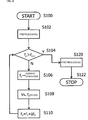
- Fig. 8 illustrates an example of a flow of the controller 20.
- An operator transmits start of measurement to the controller 20 by an output signal Cio from the input/output device 26.
- the controller 20 executes preprocessing (step S102).
- the preprocessing includes a process for setting the frequency f 2 of the current generator 12 to the minimum frequency f 2,0 .
- it is determined whether the frequency f 2 is higher than the maximum frequency f 2,n step S104). If the frequency f 2 is higher than the maximum frequency f 2,n (Y of step S104), postprocessing (step S120) is executed and the measurement ends (step S122).
- the maximum frequency f 2,n means a maximum value of a frequency that can be supplied by the current generator 12 and the minimum frequency f 2,1 means a minimum value of a frequency that can be supplied by the current generator 12. If the current generator 12 can supply an alternating current, a zero frequency (that is, a direct current) may be included in the minimum frequency. A constant current generated in the magnetic element 11 can detect a constant current overlapped in the measurement target circuit 90.
- step S106 If the frequency f 2 is not higher than the maximum frequency f 2,n (N of step S104), a value of f 2 is transmitted to the current generator 12 to make it output a current of the frequency f 2 (step S106).
- Vs both end voltage
- Vs of the magnetic element 11 through the low-pass filter 16 is measured by the voltage meter 18.
- the output Vs of the voltage meter 18 and the value of f 2 are recorded in the memory 22 (step S108).
- the frequency f 2 of the current generator 12 is changed by a predetermined frequency ⁇ f 2 (step S110).
- step S104 The controller 20 records the output Vs of the voltage meter 18 and f 2 at that time while increasing the frequency f 2 of the current generator 12, until new f 2 becomes higher than the maximum frequency f 2,n .
- the output Vs through the low-pass filter 16 represented by the formula (14) is obtained from the voltage meter 18.
- the both end voltage (Vs) of the magnetic element 11 observed through the low-pass filter 16 decreases.
- the both end voltage (Vs) of the magnetic element 11 measured through the low-pass filter 16 again increases.
- step S110 If, as a result of increasing f 2 by ⁇ f 2 in step S110, f 2 becomes higher than the maximum frequency f 2,n , the measurement ends and a flow of the process changes to Y of step S104. If the process proceeds to step S120, the controller 20 executes the postprocessing (step S120) and the process stops (step S122).
- the postprocessing may be a process for outputting the frequency f 2 and the output result Vs of the voltage meter 18 recorded in the memory 22 to the input/output device 26.
- the current generator 12 when a constant voltage oscillator of variable frequencies is used as the current generator 12, the current I 1 flowing in the magnetic element 11 is changed by the frequency f 2 . Therefore, a correction value is prepared for each frequency and the correction value is recorded in the memory 22.
- a value of the output Vs of the voltage meter 18 is preferably corrected using the correction value of the memory 22.
- Obtained data is the frequency f 2 of the current generator 12 and the output Vs of the voltage meter 18.
- a horizontal axis to be the frequency f 2 of the current generator 12 and a vertical axis to be the output Vs (it may be a value after correction using the correction value) of the voltage meter 18 to plot these data, a spectrum of the current flowing in the conducting wire 92 of the measurement target circuit 90 is obtained (refer to Fig. 7D ).
- Fig. 9 illustrates a configuration of an electric current measurement apparatus 2 according to this embodiment.
- the same components as those in the first embodiment are denoted with the same reference numerals and description thereof is omitted.
- a Hall element hereinafter, referred to as the "Hall element 31" is used as a magnetic element 31 in a sensor unit 10.
- measurement voltage terminals 31b are provided at a right angle with drive current terminals 31a. Therefore, current terminals 10c and voltage terminals 10d provided in a casing 10a of the sensor unit 10 are disposed at positions of the right angle.
- a plurality of current generators 32a, 32b, and 32c are connected to the current terminal 10c connected to the drive current terminal 31a of the Hall element 31.
- connection switches 33a, 33b, and 33c are disposed between the current generators 32a, 32b, and 32c and the current terminal 10c. Opening and closing of these connection switches 33a, 33b, and 33c are controlled by instruction signals Csa, Csb, and Csc from a controller 20.
- Output frequencies of the current generators 32a, 32b, and 32c are set as f 2,1 , f 2,2 , and f 2,3 .
- the three current generators are shown.
- the number of current generator may be one and may be two or more.
- f 2,1 may be a zero frequency, as described in the first embodiment. That is, f 2,1 may be a direct current.
- f 2,1 may be a direct current.
- I 2 an alternating-current component of a measurement target circuit 90
- bias current bias current
- step S200 when the process starts (step S200), preprocessing is executed (step S202).
- the preprocessing includes a process for setting n to 1.
- step S204 it is determined whether n is larger than the number Maxn of current generator s.
- n is not more than Maxn (N of step S204)
- a connection switch is closed such that an n-th current generator is connected to the Hall element 31 (step S206).
- an output Vs of a voltage meter 18 and a frequency f 2,n of a flowing current are recorded (step S208).
- n is incremented (step S210) and the process returns to step S204.
- step S220 postprocessing (step S220) is executed and the process stops (step S222).
- frequencies of currents flowing in the magnetic element 31 are limited to the number of current generators 32. Therefore, this is particularly effective for the case in which a frequency of a current flowing in the measurement target circuit 90 is previously determined or the case in which a frequency to be measured is previously determined.
- the electric current measurement apparatuses 1 and 2 can measure a spectrum of the current flowing in the measurement target circuit 90 with the very simple configuration.
- the current can be measured with precision of a bandwidth of a double of a cutoff frequency fc of a low-pass filter 16 and measurement with high Q is enabled.
- the example of using the magnetoresistive element as the magnetic element 11 in the first embodiment and using the Hall element as the magnetic element 11 in the second embodiment has been described. However, these elements may be changed. That is, the Hall element may be used as the magnetic element 11 according to the first embodiment and the magnetoresistive element may be used as the magnetic element 31 according to the second embodiment.
- Fig. 11 illustrates a configuration of an electric current measurement apparatus 3 according to this embodiment.
- the electric current measurement apparatus 3 has the measurement principlesimilar tosuper heterodyne. That is, a predetermined frequency band MB is previously set as an intermediate frequency. Next, a current (current I 1 of a measurement target circuit 90) of a frequency f 1 higher than the intermediate frequency is converted into a signal of a band MB by frequency conversion by a magnetic element 11 and a current generator 12. That is, a signal of a frequency of f 1 - f 2 is down-converted to the band MB. In addition, the signal of the frequency of f 1 - f 2 is amplified once as a signal of the intermediate frequency. Then, measurement using a different magnetic element and a different current generator (a frequency is f 3 ) is performed again with respect to the signal of the frequency of f 1 - f 2 .
- This technology is mainly used to exclude an influence of a negative frequency, when a transmission signal having a constant band is down-converted from a carrier signal to a baseband signal.
- a merit using this technology is particularly effective for the case in which signal strength of the frequency f 1 - f 2 down-converted to a cutoff frequency fc or less is small.
- the signal strength of the frequency f 1 - f 2 is small, an SNR of a direct-current voltage observed through a low-pass filter 16 is lowered and measurement precision is lowered.
- the magnetic element may be a magnetoresistive element or a Hall element.
- a magnetic element and a current generator not provided in the electric current measurement apparatus 1 described in the first embodiment are called a second magnetic element 41 and a second current generator 42, respectively. Therefore, the magnetic element and the current generator existing in the electric current measurement apparatus 1 are called a first magnetic element 11 and a first current generator 12, respectively.
- individual terminals are called first drive current terminals 11a and first measurement voltage terminals 11b.
- a sensor unit including a casing 10a is called a first sensor unit 10.
- Configurations of the measurement target circuit 90, the first magnetic element 11, and the first current generator 12 are the same as the configurations in the first embodiment. Therefore, a holder 10b is provided on the casing 10a and a conducting wire 92 of the measurement target circuit 90 is fixed by the holder 10b in a predetermined position relation with the first magnetic element 11.
- the first measurement voltage terminals 11b (voltage terminals 10d) are connected to a current amplifier 38.
- an output line 39 of the current amplifier 38 is connected to a ground. If the current amplifier 38 can flow a current proportional to an inter-terminal voltage of the first measurement voltage terminals 11b, a configuration is not limited in particular. For example, a voltage amplifier including a voltage booster may be used.
- the current amplifier 38 amplifies only a signal of the band MB of the intermediate frequency and does not amplify the other signals. Therefore, the current amplifier does not need to have a flat frequency characteristic. In other words, the current amplifier may have a band-pass filter of the band MB.
- the second magnetic element 41 is provided on the output line 39 of the current amplifier 38.
- the second magnetic element 41 may be the same as the magnetic element 11.
- the second magnetic element may be a Hall element.
- the second magnetic element 41 has a bias mechanism.
- the second magnetic element is provided with a bias mechanism having conductor patterns of a barber pole type and a center tap connected to a ground, illustrated in Fig. 5A .
- the second magnetic element 41 and the output line 39 are embedded in the electric current measurement apparatus 3. That is, the output line 39 and the second magnetic element 41 may not be configured separately. Therefore, like the position relation illustrated in Fig. 3A , the output line 39maybe disposed to adhere closely to a portion on or below the second magnetic element 41 in a thickness direction and may be fixed.
- the output line 39 and the second magnetic element 41 may be formed integrally.
- the second magnetic element 41 and the output line 39 may be molded by a resin or the second magnetic element 41 and the output line 39 may be manufactured integrally by photolithography.
- This portion is called a second sensor unit 40.
- a casing is not illustrated.
- the second magnetic element 41 may be stored in the casing and weather resistance may be increased.
- a holder to fix a position relation of the output line 39 and the second magnetic element 41 may be provided.
- a pair of second drive current terminals 41a and a pair of second measurement voltage terminals 41b are provided in the second magnetic element 41.
- the second current generator 42 is connected to the second drive current terminal 41a.
- a low-pass filter 16 is connected to the second measurement voltage terminal 41b.
- a voltage meter 18 is connected to the low-pass filter 16.
- the voltage meter 18 is connected to a controller 50 via an A/D converter 24.
- the configuration other than the low-pass filter 16 is the same as the configuration of the electric current measurement apparatus 1 illustrated in the first embodiment.
- the controller 50 performs processes different from those performed by the controller 20.
- the second current generator 42 generates currents of different frequencies in a longitudinal direction of the second magnetic element 41, by an instruction signal Cm of the controller 50.
- a current of the second current generator 42 is set as a current I 4 and a frequency is set as f 3 .
- the second current generator 42 may generate a current of a frequency until the band MB of Fig. 12A . In other words, a current of a frequency in the band MB may be flown.
- preprocessing is executed (step S302).
- the preprocessing includes a process for setting a frequency f 2 of the first current generator 12 to a minimum frequency f 2,1 and setting a frequency f 3 of the second current generator 42 to a minimum frequency f 3,0 .
- a frequency of a current output by the second current generator 42 may be limited to a lower frequency fmd to an upper frequency fmu of a band MB of an intermediate frequency (refer to Fig. 12B ).
- the minimum frequency f 3,0 output by the second current generator 42 is the lower frequency fmd of the band MB and the maximum frequency f 3,m is the upper frequency fmu.
- step S304 it is determined whether the frequency f 2 is higher than the maximum frequency f 2,n (step S304). If the frequency f 2 is higher than the maximum frequency f 2,n (Y of step S304), postprocessing (step S320) is executed and the measurement ends (step S322).
- the maximum frequency f 2,n means a maximum value of a frequency that can be supplied by the first current generator 12 and the minimum frequency f 2,1 means a minimum value of a frequency that can be supplied by the first current generator 12. If the first current generator 12 can supply an alternating current, a zero frequency (represented as a constant current "f 2,0 ”) may be included in the minimum frequency. As a constant current flowing in the magnetic element 11, a constant current overlapped on the measurement target circuit 90 can be detected.
- a value of f 2 is transmitted to the first current generator 12 and a current I 2 of the frequency f 2 is output to the first current generator 12 (step S306).
- Fig. 12A an example of a relation between frequencies of the current I 1 of the frequency f1 of the measurement target circuit 90 and the current I 2 of the frequency f 2 by the first current generator 12 is illustrated in Fig. 12A .
- the signals of the frequencies f 1 and f 2 are operated by the first magnetic element 11 to generate signals of f 1 - f 2 and f 1 + f 2 . These signals appear between the first measurement voltage terminals 11b.
- the current amplifier 38 to which the first measurement voltage terminal 11b is connected does not amplify frequencies other than the band MB of the intermediate frequency. Therefore, if f 1 - f 2 becomes a signal of the band MB of the intermediate frequency, a current proportional to an inter-terminal voltage of the first measurement voltage terminals 11b at that time flows from the current amplifier 38 to the output line 39. At this time, a proportional constant becomes an amplification factor of the current amplifier 38.
- the controller 50 sweeps a current of the second current generator 42. Specifically, it is determined whether the frequency f 3 is higher than the maximum frequency f 3,m (step S308). If the frequency f 3 is higher than the maximum frequency f 3,m (Y of step S308), a loop until step S314 is skipped. That is, the sweep is stopped. If the frequency f 3 is not higher than the maximum frequency f 3,m (N of step S308), a value of f 3 is transmitted to the second current generator 42 and a current of the frequency f 3 is output to the second current generator 42 (step S310).
- Fig. 12B illustrates an example of a relation of the current (frequency f 3 ) by the second current generator 42 and the current (frequency (f 1 - f 2 )) flowing in the output line 39 at that time.
- the signal of the frequency f 1 - f 2 is viewed as a fixed signal.
- the second magnetic element 41 executes an operation between the signal of the frequency f 1 - f 2 and the current of the frequency f 3 by the second current generator 42 to generate a signal of a frequency f 1 - f 2 - f 3 and a signal of a frequency f 1 - f 2 + f 3 between the second measurement voltage terminals 41b.
- step S312 the output Vs of the voltage meter 18 and the values of f 2 and f 3 are recorded in the memory 22 (step S312).
- step S314 the frequency f 3 of the second current generator 42 is changed by a predetermined frequency ⁇ f 3 (step S314).
- steps S308 to S314 a current of a certain frequency in the band MB of the intermediate frequency is down-converted to the cutoff frequency fc or less.
- Fig. 12C illustrates a relation of individual signal frequencies when the frequency of the signal (current generated by the second current generator 42) of the frequency f 3 is increased by the sweep and the signal approaches the signal of the frequency f 1 - f 2 . If the signal of the frequency f 1 - f 2 - f 3 becomes lower than the cutoff frequency fc, the signal is observed as the output voltage Vs of the direct current in the voltage meter 18.
- step S308 When it is determined in step S308 that the sweep of the current of the second current generator 42 ends (Y of step S308), the frequency f 3 is set again to an initial value f 3,0 (step S316), the frequency f 2 of the first current generator 12 is changed by the predetermined frequency ⁇ f 2 (step S318), and the process returns to step S304.
- step S304 When it is determined in step S304 that the measurement ends, the postprocessing is executed (step S320) and the process stops (step S322).
- the frequencies of f2 and f3 recorded in step S312 are plotted as illustrated in Fig. 12D where the horizontal axis shows f2 + f3 and the vertical axis shows the output Vs of the voltage meter 18. In this way, a spectrum of a current of the measurement target circuit 90 can be obtained.
- the output Vs of the vertical axis can be converted into a value of a current flowing in the measurement target circuit 90 by measuring gains of the first sensor unit 10, the current amplifier 38, and the second sensor unit 40 previously, preparing correction values, and performing compensation with the correction values.
- the correction values are stored in the memory 22 and the controller 50 can use the correction values at appropriate timing.
- f 3 is handled as the currents of the plurality of frequencies, but may be fixed to a predetermined frequency of the band MB of the intermediate frequency.
- the first current generator 12 and the second current generator 42 illustrated in Fig. 11 may change the frequencies continuously and a plurality of prepared current generators may be switched.
- a direct current may be included in the first current generator 12.
- the basic principle of the electric current measurement apparatus that can measure the frequency are described.
- a plurality of neighboring frequencies may exist and beat between signals may occur, which can make the down conversion more complicated.
- a current I 1 flowing in a conducting wire 92 and a current flowing in a magnetic element 11 are not synchronized. Therefore, phases thereof are not matched.
- an output voltage of a low-pass filter is not constant and measurement may be disabled (a measurement value is not determined). This is because a current having a frequency is not handled as a complex number. Therefore, in this embodiment, an electric current measurement apparatus 4 that can overcome a problem by handling a measurement target current as a complex number will be provided.
- Fig. 14 illustrates a configuration of the electric current measurement apparatus 4 according to the present invention.
- the electric current measurement apparatus 4 includes a first sensor unit 10 having a first magnetic element 11 and a second sensor unit 40 having a second magnetic element 41, a holder 10b that fixes a position relation of a conducting wire 92 in which a current I 1 to be measured flows and the first sensor unit 10 and the second sensor unit 40, a current generator 12 that applies a signal of a frequency f 1 to the first magnetic element 11, a phase converter 13 that applies a current the phase of which is deviated by n/2 from that of a signal of the current generator 12 to the second magnetic element 41, a first low-pass filter 16 and a second low-pass filter 17 that limit a band with respect to an inter-terminal voltage of the first magnetic element 11 and the second magnetic element 41, an amplitude vector operator 44 (VAA) that calculates a square root of a sum of squares of outputs (voltage values) of the first low-pass filter 16 and the second low
- a first instrumentation amplifier 46 and a second instrumentation amplifier 47 that amplify outputs of the first magnetic element 11 and the second magnetic element 41 may be included.
- an A/D converter 24 may be provided in a rear step of the amplitude vector operator 44.
- phase vector operator 45 (VA ⁇ ) that calculates an arctangent value from the outputs of the first low-pass filter 16 and the second low-pass filter 17 may be provided.
- the A/D converter 25 may be connected to the output of the vector operator 45.
- the amplitude vector operator 44 and the phase vector operator 45 may be executed by software by the controller 52 or other processing unit.
- the first magnetic element 11 and the second magnetic element 41 may have the configuration of Figs. 4A to 4C or Figs. 5A to 5C .
- the first magnetic element and the second magnetic element may be configured as a bridge circuit to obtain a large differential output.
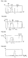
- Fig. 15 illustrates configurations of the first sensor unit 10 (first magnetic element 11) and the second sensor unit 40 (second magnetic element 41) in a case where the bridge circuit is used. Because the first sensor unit 10 and the second sensor unit 40 have the same configuration, the configuration of only the first sensor unit 10 will be described herein.
- the first sensor unit 10 includes a first magnetic element 115, a bridge resistor 60, and a bridge resistor 61.
- One end of the bridge resistor 60 is coupled with one end of the bridge resistor 61 and these one ends become one terminal of a first drive current terminal 11a (current terminal 10c).
- the other end of the bridge resistor 60 is connected to one end 115a of the first magnetic element 115, and the other end of the bridge resistor 61 is connected to the other end 115b of the first magnetic element 115.
- the first magnetic element 115 is considered as a magnetic element obtained by connecting an upper magnetoresistive element 116 and a lower magnetoresistive element 117 in the drawing ( Fig. 15 ) in series. Therefore, if a center portion 115c is used as a terminal, a bridge circuit configured by connecting a serial connection portion of the bridge resistor 60 and the magnetoresistive element 116 and a serial connection portion of the bridge resistor 61 and the magnetoresistive element 117 in parallel is formed.
- the center portion 115c becomes the other end of the first drive current terminal 11a (current terminal 10c).
- one end 115a and the other end 115b of the first magnetic element 115 become a voltage terminal 10d (measurement voltage terminal 11b).
- the second sensor unit 40 may also have the same configuration.
- the current generator 12 receives an instruction signal Cc from the controller 52 and outputs a current having a frequency and strength according to an instruction.
- the phase converter 13 receives a current supplied from the current generator 12 and outputs a current I 4 a phase of which is deviated by ⁇ /2 from a phase of a current I 2 output by the current generator 12.
- the amplitude vector operator 44 and the phase vector operator 45 transmit each of the outputs as signals Sva and Sv ⁇ to the controller 52, respectively.
- the controller 52 is connected to the current generator 12, the amplitude vector operator 44, and the phase vector operator 45.
- an instruction signal Cc is transmitted to the current generator 12 to control an output value output by the current generator 12, a frequency, and output timing.
- the signals Sva from the amplitude vector operator 44 and Sv ⁇ from the phase vector operator 45 are obtained and a relation of the frequency of the current output by the current generator 12 and the signals Sva and Sv ⁇ is output to an input/output device 26.
- a magnetic field is generated around the conducting wire 92 by the current I 1 flowing in the conducting wire 92 of the measurement target circuit 90. Meanwhile, an alternating current I 2 flows in the first magnetic element 11.
- an alternating current I 4 which has the same frequency as a frequency of the alternating current I 2 and of which a phase is deviated by n/2 from a phase of the alternating current I 2 flows to the second magnetic element 41.
- An output voltage appearing between the measurement voltage terminals 11b (41b) of the first magnetic element 11 (second magnetic element 41) affected by the magnetic field generated by the current I 1 flowing in the conducting wire 92 while flowing the alternating current I 2 becomes a multiplication result of the current I 1 flowing in the conducting wire 92 and the current I 2 flowing in the first magnetic element 11.
- a current which is a real signal and flowing in the conducting wire 92 is multiplied by a current a phase of which is deviated by n/2, a real number component and an imaginary number component are generated. From these components, amplitude of the real signal and a phase difference of the alternating current I 2 and the current I 1 flowing in the conducting wire 92 can be acquired.
- the current I 1 flowing in the conducting wire 92 is set as Acos (2 ⁇ f 1 t + ⁇ 1 ).
- A shows amplitude.
- Signals output from the current generator 12 and the phase converter 13 are set as cos (2 ⁇ f 2 t + ⁇ 2 ) and sin (2 ⁇ f 2 t + ⁇ 2 ) , respectively.
- B is represented by a formula (17).
- the obtained amplitude W does not depend on the frequency f 1 of the current I 1 flowing in the conducting wire 92, the frequencies f 2 of the currents I 2 and I 4 flown from the current generator 12 and the phase converter 13, and ⁇ 1 and ⁇ 2 . Therefore, a stabilized value can be obtained.
- the controller 52 can display a relation of the frequency output to the current generator 12 and the amplitude W on the input/output device 26.
- a table or a correction value for converting the obtained amplitude W into a current value is stored in the memory 22. Therefore, the amplitude W may be converted into a value of a current flowing in the conducting wire 92 and may be displayed on the input/output device 26.
- An electric current measurement apparatus can be used as an electric current measurement apparatus capable of being incorporated into a device as well as a stationary electric current measurement apparatus.
Abstract
Description
- The present invention relates to an electric current measurement apparatus and an electric current measurement method that can measure a spectrum of a current flowing in a measurement target circuit.
- Recently, use of natural energy such as solar power generation and wind power generation, development of new energy such as fuel cells, and energy saving of various things including vehicles and home appliances are actively progressed due to an environmental problem. Reduction of energy consumption and reduction of power consumption are important problems of Japan and the whole world in the future.
- It is said that one of solutions thereof is measurement and display of power consumption of an electric apparatus and an electronic apparatus, and management control of storage and consumption of power. To realize this, a measurement apparatus having small size and light weight and a low cost is necessary.
- For example, a large amount of harmonic current is generated in an inverter to convert direct-current power generated by an inverter power supply or a solar battery incorporated in an air conditioner, an electric vehicle (EV), and a hybrid electric vehicle (HEV) into alternating-current power of a commercial frequency.
- In measurement of the harmonic current, the current is converted into a voltage by an ammeter (also referred to as "CT" : Current Transformer) and a shunt resistor, and the measurement using analysis (Fourier analysis) by a computer or a filter function by an electronic circuit is then performed.
- In measurement of a high frequency/harmonic current, measurement precision greatly depends on a frequency characteristic (magnetic characteristic) of the CT used for the measurement, and there is a large problem in the measurement precision and reliability in a high frequency region. At the same time, the CT having a superior high frequency characteristic is generally expensive. At the same time, in the current measurement by the CT, a size of (a casing of) the CT becomes a problem. As a result, these factors obstruct size reduction and cost reduction of the device.
- In addition, in a measurement method using the shunt resistor, enormous energy lost as a heat when a large current flows becomes a problem and insulation measures are necessary in many cases. Similar to the case of the CT, these factors obstruct the size reduction and the cost reduction of the device.
- Meanwhile, in the related art, an electric current measurement apparatus using a magnetic element is known as an electric current measurement apparatus that does not use the shunt resistor and is relatively cheap. In the present specification and claims, the "magnetic element" is an element that changes an electrical characteristic by a magnetic field from the outside of the element. Therefore, a Hall element using a semiconductor is also handled as the magnetic element.
- The magnetic element detects a magnetic field generated by a current. Therefore, current measurement using the magnetic element becomes technology called magnetic field detection widely. A clamp-type ammeter is representatively used. This is inserted into a magnetic circuit in which a conductor to which a current flows is configured using a magnetic material and a magnetic field generated by the current is detected by the magnetic element (Patent Literature 1).
- In addition, the invention in which power consumption in a measurement target circuit is measured by the magnetic element is reported (Patent Literature 2). In addition, a magnetic field measurement apparatus using a magnetic impedance effect is reported (Patent Literature 3). The magnetic impedance effect is an effect in which, when an alternating current is flown to the magnetic element and a flow of the current is unevenly distributed on only a surface of the magnetic element by a skin effect, impedance of the magnetic element changes at high sensitivity with respect to an external magnetic field.
-
- Patent Literature 1:
JP 07-104011 A - Patent Literature 2:
WO2012/105459 - Patent Literature 3:
JP 2007-322125 A - The clamp-type ammeter is normally used for measurement of a direct-current magnetic field and can display only a maximum magnetic field or an effective value when a current flowing in a measurement target circuit is an alternating current. In addition, a power meter using the magnetic element needs to be incorporated into the measurement target circuit. That is, a current of the measurement target circuit is used. However, it is not easy to measure a current that already flows to a certain circuit.
- The magnetic field measurement apparatus using the magnetic impedance effect has high sensitivity, but measurement of the alternating current flowing in the measurement target circuit is not reported.
- In addition, when a plurality of frequencies are overlapped in the measurement target circuit or frequencies of flowing currents are not known, these measurement apparatuses cannot measure the frequencies and the flowing currents.
- However, as described above, to measure power consumption of the electric apparatus or the electronic apparatus or manage storage or consumption of the power, it is necessary to detect a frequency component and an amount of each current flowing in a conducting wire to which currents of numerous frequencies overlapped flow. When the inverter is used in particular, a frequency change and a current value for each frequency need to be detected.
- The present invention has been made in view of the above problem. More specifically, according to the present invention, an electric current measurement apparatus for measuring a current flowing in a conducting wire of a measurement target circuit, includes:
- a magnetic element which is provided with drive current terminals and measurement voltage terminals;
- a holder which fixes a position relation of the magnetic element and the conducting wire;
- a current generator which outputs an alternating current of at least one frequency between the drive current terminals;
- a voltage meter which measures a voltage between the measurement voltage terminals; and
- a low-pass filter which is provided between the measurement voltage terminals and the voltage meter.
- According to the present invention, an electric current measurement method includes:
- a step of flowing an alternating current to a magnetic element disposed in the vicinity of a conducting wire to which a current of a measurement target circuit flows;
- a step of observing an inter-terminal voltage of the magnetic element through a low-pass filter;
- a step of changing a frequency of the alternating current; and
- a step of recording the inter-terminal voltage observed through the low-pass filter and the frequency of the alternating current.
- An electric current measurement apparatus according to the present invention can acquire a spectrum of a current flowing in a measurement target circuit with a simple configuration such as a magnetic element, a drive current generator, and a voltage meter. In addition, the measurement principle approximates to heterodyne and super heterodyne. However, an exclusively used circuit to perform the heterodyne is not necessary. In other words, the magnetic element may execute an operation.
- In addition, measurement can be performed with precision of a band of a cutoff frequency of a low-pass filter. For example, the measurement can be performed with precision of a band of several Hz, with respect to a frequency of MHz order. That is, when a high frequency current is measured, a current of a conducting wire of the measurement target circuit can be detected with a very high Q value.
-
-
Fig. 1 is a diagram illustrating a configuration of an electric current measurement apparatus according to the present invention. -
Fig. 2 is a partially enlarged view of a sensor unit. -
Figs. 3A and 3B are diagrams illustrating the principle of a magnetoresistive element. -
Figs. 4A to 4C are diagrams illustrating a bias mechanism. -
Figs. 5A to 5C are diagrams illustrating the case in which two barber poles are formed to face each other. -
Figs. 6A and 6B are diagrams illustrating the principle of a Hall element. -
Figs. 7A to 7D are diagrams illustrating the principle of current measurement according to the present invention. -
Fig. 8 is a diagram illustrating a process flow of the electric current measurement apparatus. -
Fig. 9 is a diagram illustrating another structure of the electric current measurement apparatus. -
Fig. 10 is a diagram illustrating a process flow of the electric current measurement apparatus illustrated inFig. 9 . -
Fig. 11 is a diagram illustrating a configuration of an electric current measurement apparatus having an intermediate frequency amplifier. -
Figs. 12A to 12D are diagrams illustrating the measurement principle of the electric current measurement apparatus ofFig. 11 . -
Fig. 13 is a diagram illustrating a measurement flow of the electric current measurement apparatus ofFig. 11 . -
Fig. 14 is a diagram illustrating a configuration of an electric current measurement apparatus executing a complex process. -
Fig. 15 is a diagram illustrating another configuration of the sensor unit. - Hereinafter, an electric current measurement apparatus according to the present invention will be described with reference to the drawings. The following description exemplifies an embodiment of the present invention and the present invention is not limited thereto. The following embodiment can be changed without departing from the gist of the present invention.
-
Fig. 1 illustrates a configuration of an electriccurrent measurement apparatus 1 according to this embodiment. Ameasurement target circuit 90 includes a power supply (referred to as "PS") 91, aload 93, and aconducting wire 92 to connect thepower supply 91 and theload 93. The electriccurrent measurement apparatus 1 includes asensor unit 10, a current generator (referred to as "CG") 12, a low-pass filter (referred to as "LPF") 16, and a voltage meter (referred to as "VM") 18. - A controller (Micro Processor Unit, described as "MPU") 20 to execute whole control, a memory (referred to as "MM") 22, an A/D converter (referred to as "A/D") 24, and an input/output device (referred to as "I/O") 26 may be further provided. A
magnetic element 11 is disposed in thesensor unit 10. Themagnetic element 11 may be a magnetoresistive element or a Hall element. In this embodiment, the case in which themagnetic element 11 is the magnetoresistive element is described. - In the
sensor unit 10, themagnetic element 11 is fixed to an inside of acasing 10a. In addition, aholder 10b (although not illustrated inFig. 1 , it is described in detail with reference toFig. 2 ) to fix a part (conducting wire 92) of themeasurement target circuit 90 is disposed. In the electriccurrent measurement apparatus 1 according to the present invention, because theconducting wire 92 in which a current flows is not clamped in a magnetic circuit, it is necessary to fix a distance between themagnetic element 11 and the conducting wire 92 (current). -
Fig. 2 illustrates an example of thesensor unit 10. Thesensor unit 10 includes thecasing 10a formed of a nonmagnetic material to hold the magnetic element 11 (not illustrated inFig. 2 ) inside and theholder 10b provided on atop surface thereof. In addition,current terminals 10c to connect the internalmagnetic element 11 and thecurrent generator 12 andvoltage terminals 10d to measure a voltage of themagnetic element 11 are provided in thecasing 10a. - The
holder 10b can fix a distance between themagnetic element 11 and theconducting wire 92. If theholder 10b is formed of a nonmagnetic material, a shape is not limited in particular. The shape of theholder 10b may be changed according to a thickness of theconducting wire 92 or a thickness of coating of theconducting wire 92. The sensor unit may be replaced with thesensor unit 10 having theholder 10b with a different shape for each thickness of theconducting wire 92. - When the
magnetic element 11 is the magnetoresistive element, theconducting wire 92 is preferably fixed to a portion on or a portion below themagnetic element 11 in a thickness direction thereof. This is because a magnetoresistive effect appears to an external magnetic field of an in-plane direction with respect to a current flowing in themagnetic element 11. - Meanwhile, when the Hall element is used for the
magnetic element 11, theholder 10b is preferably fixed to a position that is parallel to the current flowing in themagnetic element 11 and is adjacent to themagnetic element 11. This is because a Hall effect appears to an external magnetic field from a direction vertical to the in-plane direction, with respect to the current flowing in themagnetic element 11. According to a difference of kinds of the magnetoresistive element and the hall element, an appropriate relation of a portion to detect a voltage of themagnetic element 11 and theconducting wire 92 may be different from the above description. Theholder 10b may be formed to fix a position relation between themagnetic element 11 and theconducting wire 92. - Referring to
Fig. 1 again, a pair of drivecurrent terminals 11a for generating the current in themagnetic element 11 and a pair ofmeasurement voltage terminals 11b for measuring the voltage of themagnetic element 11 are provided in themagnetic element 11. The drivecurrent terminal 11a is connected to thecurrent terminal 10c provided in thecasing 10a of thesensor unit 10 and themeasurement voltage terminal 11b is connected to thevoltage terminal 10d of thecasing 10a. - Because the
magnetic element 11 used in thesensor unit 10 may be either the magnetoresistive element or the Hall element, the drivecurrent terminal 11a and themeasurement voltage terminal 11b may be commonly used or may be in a position relation of a right angle. When themagnetic element 11 is the magnetoresistive element, the drivecurrent terminal 11a and themeasurement voltage terminal 11b are often commonly used. In addition, when themagnetic element 11 is the Hall element, the drivecurrent terminal 11a and themeasurement voltage terminal 11b are often in the position relation of the right angle. - The current generator 12 (CG) is a current source to supply an alternating current. The
current generator 12 is connected to the current terminal 10c of thesensor unit 10. Because the current terminal 10c of thesensor unit 10 and the drive current terminal 11a of themagnetic element 11 are connected to each other, it may be said that thecurrent generator 12 is connected to the drivecurrent terminal 11a. - In the
current generator 12, a frequency is preferably variable. This is because the electriccurrent measurement apparatus 1 measures a current of a frequency almost equal to a frequency generated by thecurrent generator 12 among currents flowing in theconducting wire 92. A plurality of ACcurrent generators 12 may be provided and may be sequentially switched. Such a configuration will be illustrated in a second embodiment. When a frequency to be measured is previously known, it is not excluded that thecurrent generator 12 supplies a current of only the frequency. - In addition, the
current generator 12 may be a constant voltage source as well as a constant current source. A frequency characteristic of the current flowing in themagnetic element 11 can be known by previously measuring the frequency characteristic. Therefore, measurement sensitivity depending on an amount of the current flowing in themagnetic element 11 can be corrected thereafter. Particularly, when the constant voltage source is used as thecurrent generator 12, impedance of themagnetic element 11 is changed according to a frequency. For this reason, an amount of flowing current is different according to the frequency. Therefore, preferably, an amount of flowing current is previously measured for each frequency and a table or a correction value is prepared. - The
voltage meter 18 is connected to themeasurement voltage terminal 11b of themagnetic element 11 via thevoltage terminal 10d provided in thecasing 10a. Because themeasurement voltage terminal 11b and thevoltage terminal 10d are connected to each other, it may be said that thevoltage meter 18 is connected to themeasurement voltage terminal 11b. Thevoltage meter 18 may have an appropriate amplifier inside and a direct-current voltage may be measured. This is because thevoltage meter 18 measures only a voltage between both ends of themagnetic element 11 through the low-pass filter 16. - In addition, the low-pass filter 16 (referred to as the LPF) is disposed between the
magnetic element 11 and thevoltage meter 18. A cutoff frequency fc of the low-pass filter 16 may be fixed. More preferably, an active filter has an attenuation rate changed by an external control signal. In addition, in the case of a configuration in which the cutoff frequency fc can be changed, because a measurement bandwidth at the time of measuring a current can be changed, this is preferable. - A one-chip computer is suitable for the
controller 20. Of course, other configuration is not excluded. Thecontroller 20 is connected to thecurrent generator 12 and thevoltage meter 18. When the cutoff frequency fc of the low-pass filter 16 is variable and can be controlled by thecontroller 20, thecontroller 20 may be connected to the low-pass filter 16. Thecontroller 20 can transmit an instruction signal Cc to thecurrent generator 12 to control timing for generating current and the magnitude and the frequency of the generated current. In addition, the cutoff frequency fc of the low-pass filter 16 can be changed by an instruction signal Cf. In addition, a measurement signal Sv from thevoltage meter 18 can be received. - The input/
output device 26 capable of operated by an operator and thememory 22 may be connected to thecontroller 20. This is because the controller performs start of measurement, progress of the measurement, display of measurement data, and storage of the measurement data. Thecontroller 20 can exchange an output signal Cio and an input signal Sio with the input/output device 26. The measurement data is included in the output signal Cio and an instruction signal for thecontroller 20 is included in the input signal Sio. In addition, the A/D converter 24 may be disposed between thecontroller 20 and thevoltage meter 18. This is because an output of thevoltage meter 18 may be an analog signal. - Next, the
magnetic element 11 will be described in detail. Themagnetic element 11 has a property that a current flow is changed by a magnetic field applied from the outside. The change of the current flow may be observed by a voltage of a current direction and may be observed by a voltage of a direction perpendicular to the current direction, with respect to the element. A representative example of the former is the magnetoresistive effect and a representative example of the latter is the Hall effect. -
Figs. 3A and 3B are graphs illustrating the magnetoresistive element and the magnetoresistive effect. In amagnetoresistive element 100, amagnetic film 104 is formed on a strip-shapedsubstrate 102. A direction from oneend 104a of a strip shape to theother end 104b is called a longitudinal direction. Themagnetic film 104 is preferably formed such that a magnetization easy axis is induced in the longitudinal direction. - In the
magnetoresistive element 100, a current 105 flows in the longitudinal direction. In addition, the magnetoresistive element is disposed such that the longitudinal direction is matched with a direction in which a current I1 of theconducting wire 92 of the measurement target circuit flows. InFig. 3A , an aspect where theconducting wire 92 of the measurement target circuit is disposed below thesubstrate 102 is illustrated. When the current I1 flows in theconducting wire 92, an external magnetic field Hex is generated in a surrounding portion thereof. The external magnetic field Hex inclines magnetization of themagnetic film 104 of the longitudinal direction from the magnetization easy axis. That is, the direction of the current 105 flowing in themagnetic film 104 and the direction of the magnetization change. At this time, the magnetoresistive effect is generated and electrical resistance of themagnetic film 104 changes. -
Fig. 3B illustrates a graph illustrating a general magnetoresistive effect. A horizontal axis shows an external magnetic field Hex (A/m) applied from a direction perpendicular to the longitudinal direction of themagnetic film 104 and a vertical axis shows electrical resistance (hereinafter, simply referred to as a "resistance value") Rmr (Q) of the longitudinal direction of themagnetic film 104. The electrical resistance of themagnetic film 104 when the external magnetic field Hex is not applied is set as Rm0. If the external magnetic field Hex is applied to themagnetoresistive element 100, the electrical resistance is decreased by ΔRmr. - In addition, the decrease in the electrical resistance Rmr does not depend on the direction (positive/negative direction) of the external magnetic field Hex. That is, the magnetoresistive effect has a characteristic of an even function with respect to the external magnetic field Hex. In addition, when the external magnetic field Hex is small, the electrical resistance Rmr changes in only the vicinity of a peak value (in the vicinity of Hex = 0) of the even function. For this reason, the change ΔRmr of the electrical resistance is small and linearity is also low. That is, if an operation point P is at a point where the external magnetic field Hex is zero, this is not preferable for an element used for a sensor. The operation point P means a point when the external magnetic field Hex is zero on a curve showing the magnetoresistive effect and at this time, a value of the electrical resistance is Rm0.
-
Figs. 4A and 4B illustrate an improved magnetoresistive element.Fig. 4C illustrates a graph corresponding toFig. 3B .Fig. 4C illustrates a state in which the operation point P is moved to a point shown by areference numeral 107 by previously applying a bias magnetic field Hbias to the magnetoresistive element. As such, by setting the operation point P to an inclined portion of a characteristic curve showing the magnetoresistive effect, even though the external magnetic field Hex is small, the change in the electrical resistance Rmr increases and the direction of the external magnetic field Hex can be distinguished in the direction of the change of the resistance value. More specifically, as illustrated inFig. 4A , the bias magnetic field Hbias may be applied from the direction perpendicular to the longitudinal direction of the strip-shaped magnetoresistive element. -
Fig. 4B illustrates amagnetoresistive element 112. Themagnetoresistive element 112 is obtained by forming an inclined continuous pattern 113 (pattern of abarberpole type) on a surface of themagnetic film 104 with a conductor such as copper. Because a current I2 flowing between thecontinuous pattern 113 of the inclined conductor flows in a shortest distance of the inclined pattern, the current I2 flows in an inclined direction when viewed from the longitudinal direction (direction where the magnetization easy axis is formed). Even though the bias magnetic field Hbias is not used, when the external magnetic field Hex is zero, the directions of the current and the magnetization are inclined in themagnetoresistive element 112. For this reason, themagnetoresistive element 112 has an effect that the bias magnetic field Hbias is applied. That is, as illustrated inFig. 4C , the operation point P is set to the inclined portion of the characteristic curve. - In the present specification, bias mechanism means not only providing a magnet for bias, but also what has an effect having an apparent bias magnetic field Hbias due to a pattern configuration of the conductor as illustrated in
Fig. 4B . -
Fig. 5A illustratesamagnetoresistiveelement 115 in which two patterns of a barber pole type are disposed to face each other. In the drawing, an upper magnetoresistive element is represented by areference numeral 116 and a lower magnetoresistive element is represented by areference numeral 117. In addition, a graph showing a magnetoresistive effect of themagnetoresistive element 116 is illustrated inFig. 5B and a graph showing a magnetoresistive effect of themagnetoresistive element 117 is illustrated inFig. 5C . - In the
magnetoresistive element 115, acenter portion 115c is connected to a ground (center tap) and the current I2 flows from oneend 115a to theother end 115b. At this time, an inclined direction of the current I2 depends on inclined patterns. - At this time, in the
magnetoresistive element 116, electrical resistance between the terminal 115a and thecenter portion 115c is decreased by ΔRmr and in themagnetoresistive element 117, electrical resistance between thecenter portion 115c and the terminal 115b is increased by ΔRmr. Because thecenter portion 115c is connected to a ground, the electrical resistance in themagnetoresistive element 117 increases to a minus side. - Therefore, the electrical resistance decreases by 2ΔRmr between the
terminals magnetoresistive element 115. Themagnetic element 11 ofFig. 1 exemplifies this type. That is, themagnetic element 11 has the center tap that is connected to a ground. -
Figs. 6A and 6B illustrate aHall element 120 and a characteristic thereof. A Hall effect appears when a current flowing through theHall element 120 is unevenly distributed in the element due to a magnetic field applied from a direction perpendicular to a flow of the current and a potential difference is generated. - The current I2 flows from one
end 120a to theother end 120b of theHall element 120. Meanwhile, theconducting wire 92 of the measurement target circuit is disposed to be adjacent to theHall element 120. The external magnetic field Hex generated by the current I1 flowing in theconducting wire 92 passes from abottom surface 120d to atop surface 120u of theHall element 120. In this case, the flowing current I2 receives force and is distributed in awidth direction 120f of theHall element 120. By the uneven distribution, a potential difference is generated in the width direction (120e and 120f) of theHall element 120. The potential difference is called a Hall voltage -
Fig. 6B illustrates a graph showing a characteristic thereof. A horizontal axis shows the external magnetic field Hex. In addition, a vertical axis shows the Hall voltage VH. In theHall element 120, when the external magnetic field Hex has the predetermined magnitude, a substantiallylinear portion 122 is observed. If the external magnetic field Hex is more than a predetermined value, aportion 123 in which the Hall voltage VH is saturated is observed. An embodiment using theHall element 120 is illustrated in a second embodiment. - Next, the measurement principle of the electric
current measurement apparatus 1 according to the present invention will be described with reference toFig. 1 again. It is assumed that the current I1 flows in themeasurement target circuit 90 and the current I2 flows in themagnetic element 11. A magnetic field H generated in the vicinity of theconducting wire 92 of themeasurement target circuit 90 by theconducting wire 92 is represented by a formula (1). In the following description of formulae, the magnetic field H may be replaced with the external magnetic field Hex.
- Here, α is a proportional constant. When the
magnetic element 11 is disposed in the vicinity of theconducting wire 92, themagnetic element 11 receives the magnetic field H generated by theconducting wire 92 and the resistance value Rmr is changed by the magnetoresistive effect. When a change in the resistance value is set as ΔRmr, ΔRmr is represented by a formula (2).
- Here, β is also a proportional constant. If the formula (1) is substituted for the formula (2), a formula (3) is obtained.

- Because the current I2 flows to the
magnetic element 11, a change ΔVmr of a voltage between the terminals of themagnetic element 11 is represented by a formula (4), by the formula (3).
- Assuming that electrical resistance of the
magnetic element 11 when the magnetic field H is not applied from the outside is set as Rm0, the both end voltage Vmr of themagnetic element 11 is represented by a formula (5).
- The current I1 flowing in the
measurement target circuit 90 and the current I2 flowing in themagnetic element 11 are represented by formulae (6) and (7), respectively.

- Here, f1 and f2 show frequencies and t shows a time. "n" shows a circular constant.
- When the formulae (6) and (7) are substituted for the formula (5) and the formulae (1) to (3) are considered, the both end voltage Vmr of the
magnetic element 11 is represented by a formula (8).
- As represented by the formula (8), a voltage Vmr having two frequency components (f1 - f2 and f1 + f2) of αβγI1I2cos2π(f1 - f2)t and αβγI1I2cos2π(f1 + f2)t is observed in both ends of the
magnetic element 11. In addition, γ is a proportional constant. - Here, by observing the both end voltage Vmr of the
magnetic element 11 through the low-pass filter 16 having a cutoff frequency fc which is | f1 - f2 | (| | shows an absolute value) or less, the frequency component of f1 + f2 is not observed. At this time, a voltage Vs is represented by a formula (9).
- If the cutoff frequency fc is sufficiently decreased and a frequency f2 of the current I2 flowing in the
magnetic element 11 is sequentially changed, a voltage Vs represented by a formula (10) is observed when the frequency f2 is in the vicinity of the frequency f1.
- This is because f1 - f2 approaches zero and thus a term of cosine (cos) of the formula (9) is regarded as 1.
- That is, the current I2 of the frequency f2 flowing in the
conducting wire 92 can be observed as a current spectrum of a measurement bandwidth 2fc (when a complex filter is used, a bandwidth is fc). As such, applying the signal of the frequency f2 to the signal of the frequency f1 to obtain a signal of a frequency f1 - f2 lower than f1 is called down conversion. -
Figs. 7A to 7D illustrate this relation. InFigs. 7A to 7C , a horizontal axis shows a frequency f and a vertical axis shows an output Vs of thevoltage meter 18. A frequency of the current I1 flowing in themeasurement target circuit 90 is set as f1. Referring toFig. 7A , the current I2 of the frequency f2 flows from thecurrent generator 12 of the electriccurrent measurement apparatus 1 and the current I1 of the frequency f1 flows in theconducting wire 92 of themeasurement target circuit 90. In this case, in both ends of themagnetic element 11, signals of f1 - f2 and f1 + f2 are generated as represented by the formula (8). - Next, the frequency f2 of the
current generator 12 is increased. Referring toFig. 7B , when the frequency f2 approaches the frequency f1 of the current I1 flowing in themeasurement target circuit 90, a value of f1 - f2 decreases and a frequency thereof approaches zero. In contrast, a frequency of f1 + f2 increases. - Referring to
Fig. 7C , when the frequency f2 of the current I2 of thecurrent generator 12 further approaches the frequency f1 of the current I1, f1 - f2 becomes a low frequency and becomes less than the cutoff frequency fc. A signal of the frequency f1 - f2 that becomes the cutoff frequency fc or less can be observed as the voltage Vs by thevoltage meter 18, as represented by the formula (10). That is, by sequentially changing the frequency f2 of the current I2 flowing in themagnetic element 11 to measure the both end voltage of themagnetic element 11, the magnitude and the frequency f1 of the current I1 flowing in theconducting wire 92 can be detected. - In
Fig. 7D , a horizontal axis shows the frequency f2 of thecurrent generator 12 and a vertical axis shows the output Vs of thevoltage meter 18. At the side of the electriccurrent measurement apparatus 1, the frequency f2 of the current I2 flowing in themagnetic element 11 is already known and a value of the both end voltage of themagnetic element 11 through the low-pass filter 16 can be known by the output Vs from thevoltage meter 18. Therefore, values of the horizontal and vertical axes ofFig. 7D are data that can be obtained at the side of the electriccurrent measurement apparatus 1.Fig. 7D can be displayed on the input/output device 26 by thecontroller 20. - As such, by setting the horizontal axis to be the frequency f2 of the
current generator 12 and the vertical axis to be the direct-current component (Vs) of the both end voltage of themagnetic element 11, the current I1 flowing in theconducting wire 92 of themeasurement target circuit 90 can be measured. The vertical axis is corrected with an appropriate correction value, so that the vertical axis can be converted into strength of the current I1. As described above, in the electriccurrent measurement apparatus 1 according to the present invention, a current spectrum of themeasurement target circuit 90 can be obtained without using a complex circuit such as heterodyne and super heterodyne. - This relation is realized as well even when frequencies f1 of the current I1 flowing in the
measurement target circuit 90 are plural. For example, the current I1 flowing in themeasurement target circuit 90 represented by the formula (6) is represented by a formula (11).
- Here, n shows a natural number and f1,n shows a frequency of an n-th current flowing in the
conducting wire 92. At this time, amplitude of the current is In. If the current I2 flowing in themagnetic element 11 is set as the same as the formula (7) and the formulae (11) and (7) are substituted for the formula (5), a terminal voltage Vmr of themagnetic element 11 is represented by a formula (12).
- By setting the cutoff frequency fc lower than | f1,n - f2 |, Vmr is represented by a formula (13).

- Similar to the case in which the current I1 of the
measurement target circuit 90 has only the frequency f1, by sequentially changing the frequency f2 of the current I2 flowing in themagnetic element 11, a voltage Vs observed when f2 is in the vicinity of f1,n is represented by a formula (14).
- In addition, a bandwidth when the voltage is measured is 2fc. The above description is realized equally even when the
magnetic element 11 is the Hall element. - Assuming the above description, an operation of the electric
current measurement apparatus 1 will be described with reference toFig. 1 again. Thecurrent generator 12 flows a current from a minimum frequency f2,0 to a maximum frequency f2,n. For simplification, it is assumed that current having two kinds of frequencies flows in themeasurement target circuit 90. These frequencies are set as f1,1 and f1,2. In this case, f1,1 < f1,2 is satisfied. Theconducting wire 92 of themeasurement target circuit 90 is fixed to theholder 10b (refer toFig. 2 ) of thesensor unit 10. In addition, it is assumed that a correction value for themagnetic element 11 is already acquired. - The correction value includes a value capable of converting the both end voltage of the
magnetic element 11 to become the same frequency and the same value as the current flowing in theconducting wire 92. In addition, the correction value may be previously determined and may be recorded in thememory 22. - The following process flow is executed by the
controller 20, but may be executed manually.Fig. 8 illustrates an example of a flow of thecontroller 20. An operator transmits start of measurement to thecontroller 20 by an output signal Cio from the input/output device 26. When the measurement starts (step S100), thecontroller 20 executes preprocessing (step S102). The preprocessing includes a process for setting the frequency f2 of thecurrent generator 12 to the minimum frequency f2,0. In addition, it is determined whether the frequency f2 is higher than the maximum frequency f2,n (step S104). If the frequency f2 is higher than the maximum frequency f2,n (Y of step S104), postprocessing (step S120) is executed and the measurement ends (step S122). - Here, the maximum frequency f2,n means a maximum value of a frequency that can be supplied by the
current generator 12 and the minimum frequency f2,1 means a minimum value of a frequency that can be supplied by thecurrent generator 12. If thecurrent generator 12 can supply an alternating current, a zero frequency (that is, a direct current) may be included in the minimum frequency. A constant current generated in themagnetic element 11 can detect a constant current overlapped in themeasurement target circuit 90. - If the frequency f2 is not higher than the maximum frequency f2,n (N of step S104), a value of f2 is transmitted to the
current generator 12 to make it output a current of the frequency f2 (step S106). In addition, the both end voltage (Vs) of themagnetic element 11 through the low-pass filter 16 is measured by thevoltage meter 18. Next, the output Vs of thevoltage meter 18 and the value of f2 are recorded in the memory 22 (step S108). Next, the frequency f2 of thecurrent generator 12 is changed by a predetermined frequency Δf2 (step S110). - In addition, the process returns to step S104. The
controller 20 records the output Vs of thevoltage meter 18 and f2 at that time while increasing the frequency f2 of thecurrent generator 12, until new f2 becomes higher than the maximum frequency f2,n. - If the frequency f2 of the
current generator 12 becomes a value in the vicinity of f1,1, the output Vs through the low-pass filter 16 represented by the formula (14) is obtained from thevoltage meter 18. In addition, if a difference of f2 with f1,1 increases, the both end voltage (Vs) of themagnetic element 11 observed through the low-pass filter 16 decreases. In addition, if f2 becomes a value in the vicinity of f1,2, the both end voltage (Vs) of themagnetic element 11 measured through the low-pass filter 16 again increases. - If, as a result of increasing f2 by Δf2 in step S110, f2 becomes higher than the maximum frequency f2,n, the measurement ends and a flow of the process changes to Y of step S104. If the process proceeds to step S120, the
controller 20 executes the postprocessing (step S120) and the process stops (step S122). - Here, the postprocessing (step S120) may be a process for outputting the frequency f2 and the output result Vs of the
voltage meter 18 recorded in thememory 22 to the input/output device 26. Particularly, when a constant voltage oscillator of variable frequencies is used as thecurrent generator 12, the current I1 flowing in themagnetic element 11 is changed by the frequency f2. Therefore, a correction value is prepared for each frequency and the correction value is recorded in thememory 22. When a measurement result is displayed, a value of the output Vs of thevoltage meter 18 is preferably corrected using the correction value of thememory 22. - Obtained data is the frequency f2 of the
current generator 12 and the output Vs of thevoltage meter 18. By setting a horizontal axis to be the frequency f2 of thecurrent generator 12 and a vertical axis to be the output Vs (it may be a value after correction using the correction value) of thevoltage meter 18 to plot these data, a spectrum of the current flowing in theconducting wire 92 of themeasurement target circuit 90 is obtained (refer toFig. 7D ). - In the above process flow, after the frequency is measured from the minimum frequency to the maximum frequency of the
current generator 12, a result is displayed. However, a range of frequencies to be measured may be determined and the frequency may be measured or a value for each measurement may be displayed. After the measurement ends, the process does not stop and the process may proceed to step S102 for the following measurement. -
Fig. 9 illustrates a configuration of an electriccurrent measurement apparatus 2 according to this embodiment. The same components as those in the first embodiment are denoted with the same reference numerals and description thereof is omitted. In the electriccurrent measurement apparatus 2, a Hall element (hereinafter, referred to as the "Hall element 31") is used as amagnetic element 31 in asensor unit 10. In theHall element 31,measurement voltage terminals 31b are provided at a right angle with drivecurrent terminals 31a. Therefore,current terminals 10c andvoltage terminals 10d provided in acasing 10a of thesensor unit 10 are disposed at positions of the right angle. - In addition, a plurality of
current generators current terminal 10c connected to the drive current terminal 31a of theHall element 31. In addition,connection switches current generators current terminal 10c. Opening and closing of theseconnection switches controller 20. Output frequencies of thecurrent generators - Here, the three current generators are shown. However, the number of current generator may be one and may be two or more.
- Here, f2,1 may be a zero frequency, as described in the first embodiment. That is, f2,1 may be a direct current. When the frequency is zero, an alternating-current component of a
measurement target circuit 90 cannot be measured. However, when a constant bias current flows in themeasurement target circuit 90, a current (constant current) having a frequency of zero is supplied as I2 to thesensor unit 10, so that a constant current component (bias current) in themeasurement target circuit 90 can be measured. - A flow of a process by the
controller 20 described below is almost the same as the flow of the process illustrated inFig. 8 . In addition, it is assumed that the number of current generators 32 is Maxn. In the case ofFig. 9 , Maxn is 3. Referring toFig. 10 , when the process starts (step S200), preprocessing is executed (step S202). The preprocessing includes a process for setting n to 1. Next, it is determined whether n is larger than the number Maxn of current generator s (step S204). - If n is not more than Maxn (N of step S204), a connection switch is closed such that an n-th current generator is connected to the Hall element 31 (step S206). At this time, an output Vs of a
voltage meter 18 and a frequency f2,n of a flowing current are recorded (step S208). Next, n is incremented (step S210) and the process returns to step S204. - If n is more than the number Maxn of current generators(Y of step S204), postprocessing (step S220) is executed and the process stops (step S222).
- In the electric
current measurement apparatus 2, frequencies of currents flowing in themagnetic element 31 are limited to the number of current generators 32. Therefore, this is particularly effective for the case in which a frequency of a current flowing in themeasurement target circuit 90 is previously determined or the case in which a frequency to be measured is previously determined. - As described above, the electric
current measurement apparatuses measurement target circuit 90 with the very simple configuration. In addition, even when a current of a high frequency is measured, the current can be measured with precision of a bandwidth of a double of a cutoff frequency fc of a low-pass filter 16 and measurement with high Q is enabled. - In addition, the example of using the magnetoresistive element as the
magnetic element 11 in the first embodiment and using the Hall element as themagnetic element 11 in the second embodiment has been described. However, these elements may be changed. That is, the Hall element may be used as themagnetic element 11 according to the first embodiment and the magnetoresistive element may be used as themagnetic element 31 according to the second embodiment. -
Fig. 11 illustrates a configuration of an electriccurrent measurement apparatus 3 according to this embodiment. The electriccurrent measurement apparatus 3 has the measurement principlesimilar tosuper heterodyne. That is, a predetermined frequency band MB is previously set as an intermediate frequency. Next, a current (current I1 of a measurement target circuit 90) of a frequency f1 higher than the intermediate frequency is converted into a signal of a band MB by frequency conversion by amagnetic element 11 and acurrent generator 12. That is, a signal of a frequency of f1 - f2 is down-converted to the band MB. In addition, the signal of the frequency of f1 - f2 is amplified once as a signal of the intermediate frequency. Then, measurement using a different magnetic element and a different current generator (a frequency is f3) is performed again with respect to the signal of the frequency of f1 - f2. - This technology is mainly used to exclude an influence of a negative frequency, when a transmission signal having a constant band is down-converted from a carrier signal to a baseband signal.
- A merit using this technology is particularly effective for the case in which signal strength of the frequency f1 - f2 down-converted to a cutoff frequency fc or less is small. When the signal strength of the frequency f1 - f2 is small, an SNR of a direct-current voltage observed through a low-
pass filter 16 is lowered and measurement precision is lowered. - However, by converting the signal of the frequency f1 - f2 to a frequency (intermediate frequency) higher than the cutoff frequency fc and amplifying the converted signal once, so that an SNR of a voltage Vs observed through the low-
pass filter 16 can be increased. When a signal having a predetermined band is overlapped to a current to be measured, the signal of the band can be demodulated. - In
Fig. 11 , description is given using the configuration ofFig. 1 basically. However, this can be equally applied to the configuration ofFig. 9 . That is, the magnetic element may be a magnetoresistive element or a Hall element. - In the electric
current measurement apparatus 3, two sets of magnetic elements and current generators are used. A magnetic element and a current generator not provided in the electriccurrent measurement apparatus 1 described in the first embodiment are called a secondmagnetic element 41 and a secondcurrent generator 42, respectively. Therefore, the magnetic element and the current generator existing in the electriccurrent measurement apparatus 1 are called a firstmagnetic element 11 and a firstcurrent generator 12, respectively. In addition, individual terminals are called first drivecurrent terminals 11a and firstmeasurement voltage terminals 11b. In addition, a sensor unit including acasing 10a is called afirst sensor unit 10. - Configurations of the
measurement target circuit 90, the firstmagnetic element 11, and the firstcurrent generator 12 are the same as the configurations in the first embodiment. Therefore, aholder 10b is provided on thecasing 10a and aconducting wire 92 of themeasurement target circuit 90 is fixed by theholder 10b in a predetermined position relation with the firstmagnetic element 11. - In the electric
current measurement apparatus 3, the firstmeasurement voltage terminals 11b (voltage terminals 10d) are connected to acurrent amplifier 38. In addition, anoutput line 39 of thecurrent amplifier 38 is connected to a ground. If thecurrent amplifier 38 can flow a current proportional to an inter-terminal voltage of the firstmeasurement voltage terminals 11b, a configuration is not limited in particular. For example, a voltage amplifier including a voltage booster may be used. - In addition, the
current amplifier 38 amplifies only a signal of the band MB of the intermediate frequency and does not amplify the other signals. Therefore, the current amplifier does not need to have a flat frequency characteristic. In other words, the current amplifier may have a band-pass filter of the band MB. - The second
magnetic element 41 is provided on theoutput line 39 of thecurrent amplifier 38. The secondmagnetic element 41 may be the same as themagnetic element 11. Here, the case in which the second magnetic element will be the magnetoresistive element is described. However, the second magnetic element may be a Hall element. Similar to the firstmagnetic element 11, the secondmagnetic element 41 has a bias mechanism. Here, it is assumed that the second magnetic element is provided with a bias mechanism having conductor patterns of a barber pole type and a center tap connected to a ground, illustrated inFig. 5A . - The second
magnetic element 41 and theoutput line 39 are embedded in the electriccurrent measurement apparatus 3. That is, theoutput line 39 and the secondmagnetic element 41 may not be configured separately. Therefore, like the position relation illustrated inFig. 3A , the output line 39maybe disposed to adhere closely to a portion on or below the secondmagnetic element 41 in a thickness direction and may be fixed. - That is, the
output line 39 and the secondmagnetic element 41 may be formed integrally. Specifically, the secondmagnetic element 41 and theoutput line 39 may be molded by a resin or the secondmagnetic element 41 and theoutput line 39 may be manufactured integrally by photolithography. This portion is called asecond sensor unit 40. In thesecond sensor unit 40, a casing is not illustrated. However, the secondmagnetic element 41 may be stored in the casing and weather resistance may be increased. In addition, a holder to fix a position relation of theoutput line 39 and the secondmagnetic element 41 may be provided. - A pair of second drive
current terminals 41a and a pair of secondmeasurement voltage terminals 41b are provided in the secondmagnetic element 41. The secondcurrent generator 42 is connected to the second drivecurrent terminal 41a. In addition, a low-pass filter 16 is connected to the secondmeasurement voltage terminal 41b. Avoltage meter 18 is connected to the low-pass filter 16. Thevoltage meter 18 is connected to acontroller 50 via an A/D converter 24. The configuration other than the low-pass filter 16 is the same as the configuration of the electriccurrent measurement apparatus 1 illustrated in the first embodiment. Thecontroller 50 performs processes different from those performed by thecontroller 20. - The second
current generator 42 generates currents of different frequencies in a longitudinal direction of the secondmagnetic element 41, by an instruction signal Cm of thecontroller 50. A current of the secondcurrent generator 42 is set as a current I4 and a frequency is set as f3. The secondcurrent generator 42 may generate a current of a frequency until the band MB ofFig. 12A . In other words, a current of a frequency in the band MB may be flown. - Next, an operation (process of the controller 50) of the electric
current measurement apparatus 3 will be described using a configuration diagram ofFig. 11 , measurement principle diagrams ofFigs. 12A to 12D , and a flow diagram ofFig. 13 . To simplify the description, it is assumed that a current of a frequency f1 flows in themeasurement target circuit 90. Even when currents of a plurality of frequencies flow in the measurement target circuit, the currents of the plurality of frequencies can be measured by the following process. - When the process starts (step S300), preprocessing is executed (step S302). The preprocessing includes a process for setting a frequency f2 of the first
current generator 12 to a minimum frequency f2,1 and setting a frequency f3 of the secondcurrent generator 42 to a minimum frequency f3,0. - Here, a frequency of a current output by the second
current generator 42 may be limited to a lower frequency fmd to an upper frequency fmu of a band MB of an intermediate frequency (refer toFig. 12B ). Here, it is assumed that the minimum frequency f3,0 output by the secondcurrent generator 42 is the lower frequency fmd of the band MB and the maximum frequency f3,m is the upper frequency fmu. - Next, it is determined whether the frequency f2 is higher than the maximum frequency f2,n (step S304). If the frequency f2 is higher than the maximum frequency f2,n (Y of step S304), postprocessing (step S320) is executed and the measurement ends (step S322).
- Here, the maximum frequency f2,n means a maximum value of a frequency that can be supplied by the first
current generator 12 and the minimum frequency f2,1 means a minimum value of a frequency that can be supplied by the firstcurrent generator 12. If the firstcurrent generator 12 can supply an alternating current, a zero frequency (represented as a constant current "f2,0") may be included in the minimum frequency. As a constant current flowing in themagnetic element 11, a constant current overlapped on themeasurement target circuit 90 can be detected. - Next, if the frequency f2 is not higher than the maximum frequency f2,n (N of step S304), a value of f2 is transmitted to the first
current generator 12 and a current I2 of the frequency f2 is output to the first current generator 12 (step S306). At this time, an example of a relation between frequencies of the current I1 of the frequency f1 of themeasurement target circuit 90 and the current I2 of the frequency f2 by the firstcurrent generator 12 is illustrated inFig. 12A . The signals of the frequencies f1 and f2 are operated by the firstmagnetic element 11 to generate signals of f1 - f2 and f1 + f2. These signals appear between the firstmeasurement voltage terminals 11b. - Meanwhile, the
current amplifier 38 to which the firstmeasurement voltage terminal 11b is connected does not amplify frequencies other than the band MB of the intermediate frequency. Therefore, if f1 - f2 becomes a signal of the band MB of the intermediate frequency, a current proportional to an inter-terminal voltage of the firstmeasurement voltage terminals 11b at that time flows from thecurrent amplifier 38 to theoutput line 39. At this time, a proportional constant becomes an amplification factor of thecurrent amplifier 38. - Next, the
controller 50 sweeps a current of the secondcurrent generator 42. Specifically, it is determined whether the frequency f3 is higher than the maximum frequency f3,m (step S308). If the frequency f3 is higher than the maximum frequency f3,m (Y of step S308), a loop until step S314 is skipped. That is, the sweep is stopped. If the frequency f3 is not higher than the maximum frequency f3,m (N of step S308), a value of f3 is transmitted to the secondcurrent generator 42 and a current of the frequency f3 is output to the second current generator 42 (step S310). -
Fig. 12B illustrates an example of a relation of the current (frequency f3) by the secondcurrent generator 42 and the current (frequency (f1 - f2)) flowing in theoutput line 39 at that time. In thesecond sensor unit 40, the signal of the frequency f1 - f2 is viewed as a fixed signal. The secondmagnetic element 41 executes an operation between the signal of the frequency f1 - f2 and the current of the frequency f3 by the secondcurrent generator 42 to generate a signal of a frequency f1 - f2 - f3 and a signal of a frequency f1 - f2 + f3 between the secondmeasurement voltage terminals 41b. - Next, the output Vs of the
voltage meter 18 and the values of f2 and f3 are recorded in the memory 22 (step S312). Next, the frequency f3 of the secondcurrent generator 42 is changed by a predetermined frequency Δf3 (step S314). By repeating steps S308 to S314, a current of a certain frequency in the band MB of the intermediate frequency is down-converted to the cutoff frequency fc or less. -
Fig. 12C illustrates a relation of individual signal frequencies when the frequency of the signal (current generated by the second current generator 42) of the frequency f3 is increased by the sweep and the signal approaches the signal of the frequency f1 - f2. If the signal of the frequency f1 - f2 - f3 becomes lower than the cutoff frequency fc, the signal is observed as the output voltage Vs of the direct current in thevoltage meter 18. - When it is determined in step S308 that the sweep of the current of the second
current generator 42 ends (Y of step S308), the frequency f3 is set again to an initial value f3,0 (step S316), the frequency f2 of the firstcurrent generator 12 is changed by the predetermined frequency Δf2 (step S318), and the process returns to step S304. When it is determined in step S304 that the measurement ends, the postprocessing is executed (step S320) and the process stops (step S322). - The frequencies of f2 and f3 recorded in step S312 are plotted as illustrated in
Fig. 12D where the horizontal axis shows f2 + f3 and the vertical axis shows the output Vs of thevoltage meter 18. In this way, a spectrum of a current of themeasurement target circuit 90 can be obtained. The output Vs of the vertical axis can be converted into a value of a current flowing in themeasurement target circuit 90 by measuring gains of thefirst sensor unit 10, thecurrent amplifier 38, and thesecond sensor unit 40 previously, preparing correction values, and performing compensation with the correction values. The correction values are stored in thememory 22 and thecontroller 50 can use the correction values at appropriate timing. - In this embodiment, f3 is handled as the currents of the plurality of frequencies, but may be fixed to a predetermined frequency of the band MB of the intermediate frequency. In addition, the first
current generator 12 and the secondcurrent generator 42 illustrated inFig. 11 may change the frequencies continuously and a plurality of prepared current generators may be switched. In addition, a direct current may be included in the firstcurrent generator 12. - In the first, second, and third embodiments, the basic principle of the electric current measurement apparatus that can measure the frequency are described. In an actual use case, a plurality of neighboring frequencies may exist and beat between signals may occur, which can make the down conversion more complicated. In addition, in the actual use case, a current I1 flowing in a
conducting wire 92 and a current flowing in amagnetic element 11 are not synchronized. Therefore, phases thereof are not matched. - When the phases are not matched, an output voltage of a low-pass filter is not constant and measurement may be disabled (a measurement value is not determined). This is because a current having a frequency is not handled as a complex number. Therefore, in this embodiment, an electric
current measurement apparatus 4 that can overcome a problem by handling a measurement target current as a complex number will be provided. -
Fig. 14 illustrates a configuration of the electriccurrent measurement apparatus 4 according to the present invention. The electriccurrent measurement apparatus 4 includes afirst sensor unit 10 having a firstmagnetic element 11 and asecond sensor unit 40 having a secondmagnetic element 41, aholder 10b that fixes a position relation of aconducting wire 92 in which a current I1 to be measured flows and thefirst sensor unit 10 and thesecond sensor unit 40, acurrent generator 12 that applies a signal of a frequency f1 to the firstmagnetic element 11, aphase converter 13 that applies a current the phase of which is deviated by n/2 from that of a signal of thecurrent generator 12 to the secondmagnetic element 41, a first low-pass filter 16 and a second low-pass filter 17 that limit a band with respect to an inter-terminal voltage of the firstmagnetic element 11 and the secondmagnetic element 41, an amplitude vector operator 44 (VAA) that calculates a square root of a sum of squares of outputs (voltage values) of the first low-pass filter 16 and the second low-pass filter 17, and acontroller 52 that is coupled to theamplitude vector operator 44 and amemory 22. - In addition, a
first instrumentation amplifier 46 and asecond instrumentation amplifier 47 that amplify outputs of the firstmagnetic element 11 and the secondmagnetic element 41 may be included. When an output of theamplitude vector operator 44 is digitally processed, an A/D converter 24 may be provided in a rear step of theamplitude vector operator 44. - In addition, a phase vector operator 45 (VAθ) that calculates an arctangent value from the outputs of the first low-
pass filter 16 and the second low-pass filter 17 may be provided. The A/D converter 25 may be connected to the output of thevector operator 45. Theamplitude vector operator 44 and thephase vector operator 45 may be executed by software by thecontroller 52 or other processing unit. - The first
magnetic element 11 and the secondmagnetic element 41 may have the configuration ofFigs. 4A to 4C orFigs. 5A to 5C . However, the first magnetic element and the second magnetic element may be configured as a bridge circuit to obtain a large differential output.Fig. 15 illustrates configurations of the first sensor unit 10 (first magnetic element 11) and the second sensor unit 40 (second magnetic element 41) in a case where the bridge circuit is used. Because thefirst sensor unit 10 and thesecond sensor unit 40 have the same configuration, the configuration of only thefirst sensor unit 10 will be described herein. - Referring to
Fig. 15 , thefirst sensor unit 10 includes a firstmagnetic element 115, abridge resistor 60, and abridge resistor 61. One end of thebridge resistor 60 is coupled with one end of thebridge resistor 61 and these one ends become one terminal of a first drivecurrent terminal 11a (current terminal 10c). The other end of thebridge resistor 60 is connected to oneend 115a of the firstmagnetic element 115, and the other end of thebridge resistor 61 is connected to theother end 115b of the firstmagnetic element 115. - The first
magnetic element 115 is considered as a magnetic element obtained by connecting anupper magnetoresistive element 116 and a lowermagnetoresistive element 117 in the drawing (Fig. 15 ) in series. Therefore, if acenter portion 115c is used as a terminal, a bridge circuit configured by connecting a serial connection portion of thebridge resistor 60 and themagnetoresistive element 116 and a serial connection portion of thebridge resistor 61 and themagnetoresistive element 117 in parallel is formed. - Here, the
center portion 115c becomes the other end of the first drivecurrent terminal 11a (current terminal 10c). In addition, oneend 115a and theother end 115b of the firstmagnetic element 115 become avoltage terminal 10d (measurement voltage terminal 11b). Thesecond sensor unit 40 may also have the same configuration. - Referring to
Fig. 14 , thecurrent generator 12 receives an instruction signal Cc from thecontroller 52 and outputs a current having a frequency and strength according to an instruction. In addition, thephase converter 13 receives a current supplied from thecurrent generator 12 and outputs a current I4 a phase of which is deviated by π/2 from a phase of a current I2 output by thecurrent generator 12. - The
amplitude vector operator 44 calculates a square root of a sum of squares, when the outputs of the first low-pass filter 16 and the second low-pass filter 17 are set as X and Y, respectively. More specifically, if the square root of the sum of the squares is set as W, W is represented by a formula (15).
- The
phase vector operator 45 calculates an arctangent value, when the outputs of the first low-pass filter 16 and the second low-pass filter 17 are set as X and Y, respectively. More specifically, if the arctangent value is set as Θ, Θ is represented by a formula (16).
- The
amplitude vector operator 44 and thephase vector operator 45 transmit each of the outputs as signals Sva and Svθ to thecontroller 52, respectively. - The
controller 52 is connected to thecurrent generator 12, theamplitude vector operator 44, and thephase vector operator 45. In addition, an instruction signal Cc is transmitted to thecurrent generator 12 to control an output value output by thecurrent generator 12, a frequency, and output timing. In addition, the signals Sva from theamplitude vector operator 44 and Svθ from thephase vector operator 45 are obtained and a relation of the frequency of the current output by thecurrent generator 12 and the signals Sva and Svθ is output to an input/output device 26. - Next, an operation of the electric
current measurement apparatus 4 will be described with reference toFig. 14 . A magnetic field is generated around theconducting wire 92 by the current I1 flowing in theconducting wire 92 of themeasurement target circuit 90. Meanwhile, an alternating current I2 flows in the firstmagnetic element 11. In addition, an alternating current I4 which has the same frequency as a frequency of the alternating current I2 and of which a phase is deviated by n/2 from a phase of the alternating current I2 flows to the secondmagnetic element 41. - When a current having the same frequency component as the frequency of the current flowing in the first
magnetic element 11 and the secondmagnetic element 41 flows in theconducting wire 92, a direct-current voltage is obtained from the first low-pass filter 16 and the second low-pass filter 17, as described in the first embodiment. - An output voltage appearing between the
measurement voltage terminals 11b (41b) of the first magnetic element 11 (second magnetic element 41) affected by the magnetic field generated by the current I1 flowing in theconducting wire 92 while flowing the alternating current I2 becomes a multiplication result of the current I1 flowing in theconducting wire 92 and the current I2 flowing in the firstmagnetic element 11. As well known, if a current which is a real signal and flowing in theconducting wire 92 is multiplied by a current a phase of which is deviated by n/2, a real number component and an imaginary number component are generated. From these components, amplitude of the real signal and a phase difference of the alternating current I2 and the current I1 flowing in theconducting wire 92 can be acquired. - This will be described simple below. The current I1 flowing in the
conducting wire 92 is set as Acos (2πf1t + θ1). Here, A shows amplitude. Signals output from thecurrent generator 12 and thephase converter 13 are set as cos (2πf2t + θ2) and sin (2πf2t + θ2) , respectively. When the signals are expressed by complex numbers and a result thereof is set as B, B is represented by a formula (17).
- Here, if the frequency f2 of the current I2 of the
current generator 12 becomes equal to the frequency f1 of the current I1 flowing in theconducting wire 92, a formula (18) is obtained.
- If B is extracted by a low-pass filter, 1/2 {Aexp[j(θ1 - θ2]} can be obtained. These components are 1/2Acos[(θ1 - θ2] and 1/2Asin[(θ1-θ2]. These are outputs of the first low-
pass filter 16 and the second low-pass filter 17. Therefore, if X is set as 1/2Acos [(θ1 - θ2] and Y is set as 1/2Asin [(θ1 - θ2], amplitude W and a phase Θ can be obtained as represented by the formulae (15) and (16). - Here, the obtained amplitude W does not depend on the frequency f1 of the current I1 flowing in the
conducting wire 92, the frequencies f2 of the currents I2 and I4 flown from thecurrent generator 12 and thephase converter 13, and θ1 and θ2. Therefore, a stabilized value can be obtained. Thecontroller 52 can display a relation of the frequency output to thecurrent generator 12 and the amplitude W on the input/output device 26. A table or a correction value for converting the obtained amplitude W into a current value is stored in thememory 22. Therefore, the amplitude W may be converted into a value of a current flowing in theconducting wire 92 and may be displayed on the input/output device 26. - An electric current measurement apparatus according to the present invention can be used as an electric current measurement apparatus capable of being incorporated into a device as well as a stationary electric current measurement apparatus. Reference Signs List
-
- 1, 2, 3
- electric current measurement apparatus
- 10
- sensor unit
- 10a
- casing
- 10b
- holder
- 10c
- current terminal
- 10d
- voltage terminal
- 11
- magnetic element (magnetoresistive element)
- 11a
- drive current terminal
- 11b
- measurement voltage terminal
- 12
- current generator (first current generator)
- 13
- phase current source (n/2 phase converter)
- 16
- (first) low-pass filter
- 17
- (second) low-pass filter
- 18
- voltage meter
- 20
- controller
- 22
- memory
- 24
- A/D converter
- 25
- A/D converter
- 26
- input/output device
- 31
- magnetic element (Hall element)
- 31a
- drive current terminal
- 31b
- measurement voltage terminal
- 32a, 32b, 32c
- current generator
- 33a, 33b, 33c
- connection switch
- 38
- current amplifier
- 39
- output line
- 40
- second sensor unit
- 41
- second magnetic element
- 41a
- second drive current terminal
- 41b
- second measurement voltage terminal
- 42
- second current generator
- 43
- phase converter
- 44
- vector operator (amplitude)
- 45
- vector operator (phase)
- 46
- first instrumentation amplifier
- 47
- second instrumentation amplifier
- 50
- controller
- 52
- controller
- 60
- bridge resistor
- 61
- bridge resistor
- 90
- measurement target circuit
- 91
- power supply
- 92
- conducting wire
- 93
- load
Claims (27)
- An electric current measurement apparatus configured to measure a current flowing in a wire of a measurement target circuit, the apparatus comprising:a magnetic element which is provided with drive current terminals and measurement voltage terminals;a holder which fixes a position relation of the magnetic element and the wire;a current generator which is capable of outputting an alternating current of at least one frequency between the drive current terminals;a voltage meter which measures a voltage between the measurement voltage terminals; anda low-pass filter which is provided between the measurement voltage terminals and the voltage meter.
- The electric current measurement apparatus according to claim 1, further comprising:a controller which is connected to at least the voltage meter and a memory.
- The electric current measurement apparatus according to claim 2, wherein a correction value to correct a value measured by the voltage meter is recorded in the memory.
- The electric current measurement apparatus according to claim 2 or 3, wherein the controller is further connected to the current generator and the controller controls a frequency of the current generator.
- The electric current measurement apparatus according to any one of claims 2 to 4, wherein the controller is further connected to the low-pass filter and controls a cutoff frequency or an attenuation rate of the low-pass filter.
- The electric current measurement apparatus according to any one of claims 1 to 5, wherein the magnetic element is a magnetoresistive element having a bias mechanism.
- The electric current measurement apparatus according to any one of claims 1 to 5, wherein the magnetic element is a Hall element.
- An electric current measurement apparatus configured to measure a current flowing in a wire of a measurement target circuit, the apparatus comprising:a first magnetic element which is provided with first drive current terminals and first measurement voltage terminals;a second magnetic element which is provided with second drive current terminals and second measurement voltage terminals;a holder which fixes a position relation of the first magnetic element and the second magnetic element and the wire;a first current generator which is capable of outputting an alternating current of at least one frequency between the first drive current terminals;a phase converter which outputs an alternating current having a phase deviated by n/2 from a phase of the alternating current output by the first current generator, between the second drive current terminals;a first low-pass filter which is connected between the first measurement voltage terminals;a second low-pass filter which is connected between the second measurement voltage terminals; andan amplitude vector operator to which the first low-pass filter and the second low-pass filter are connected, the amplitude vector operator calculating a square root of a sum of squares of outputs of the first and second low-pass filters.
- The electric current measurement apparatus according to claim 8, further comprising:a first voltage amplifier which is disposed between the first measurement voltage terminals and the first low-pass filter; anda second voltage amplifier which is disposed between the second measurement voltage terminals and the second low-pass filter.
- The electric current measurement apparatus according to claim 8 or 9, further comprising:a phase vector operator to which the first low-pass filter and the second low-pass filter are connected, the phase vector operator calculating an arctangent value of outputs of the first and second low-pass filters.
- The electric current measurement apparatus according to any one of claims 8 to 10, further comprising:a controller which is connected to the amplitude vector operator and a memory.
- The electric current measurement apparatus according to claim 11, wherein a correction value to correct a value measured by the voltage meter is recorded in the memory.
- The electric current measurement apparatus according to claim 11 or 12, wherein the controller is further connected to the first current generator and controls a frequency of the first current generator.
- The electric current measurement apparatus according to any one of claims 11 to 13, wherein the controller is further connected to the first low-pass filter and the second low-pass filter and controls a cutoff frequency or an attenuation rate of the first low-pass filter and the second low-pass filter.
- The electric current measurement apparatus according to any one of claims 8 to 14, wherein at least one of the magnetic element and the second magnetic element is a magnetoresistive element having a bias mechanism.
- The electric current measurement apparatus according to any one of claims 8 to 15, wherein at least one of the magnetic element and the second magnetic element is a Hall element.
- An electric current measurement apparatus configured to measure a current flowing in a wire of a measurement target circuit, the apparatus comprising:a first magnetic element which is provided with first drive current terminals and first measurement voltage terminals;a holder which fixes a position relation of the first magnetic element and the wire;a first current generator which is capable of outputting an alternating current of at least one frequency between the first drive current terminals;a current amplifier which generates a current proportional to a voltage between the first measurement voltage terminals in an output line;a second magnetic element which is disposed in a predetermined position relation with regard to the output line and is provided with second drive current terminals and second measurement voltage terminals;a second current generator which is capable of outputting an alternating current of at least one frequency between the second drive current terminals;a voltage meter which measures an output between the second measurement voltage terminals; anda low-pass filter which is provided between the second measurement voltage terminals and the voltage meters.
- The electric current measurement apparatus according to claim 17, further comprising:a controller which is connected to at least the voltage meter and a memory.
- The electric current measurement apparatus according to claim 18, wherein a correction value to correct a value measured by the voltage meter is recorded in the memory.
- The electric current measurement apparatus according to claim 17 or 18, wherein the controller is further connected to the first current generator and controls a frequency of the first current generator.
- The electric current measurement apparatus according to any one of claims 17 to 20, wherein the controller is further connected to the second current generator and controls a frequency of the second current generator.
- The electric current measurement apparatus according to any one of claims 18 to 21, wherein the controller is further connected to the low-pass filter and controls a cutoff frequency or an attenuation rate of the low-pass filter.
- The electric current measurement apparatus according to any one of claims 17 to 22, wherein at least one of the magnetic element and the second magnetic element is a magnetoresistive element having a bias mechanism.
- The electric current measurement apparatus according to any one of claims 17 to 22, wherein at least one of the magnetic element and the second magnetic element is a Hall element.
- An electric current measurement method comprising:a step of generating an alternating current in a magnetic element disposed in a vicinity of a wire in which a current of a measurement target circuit flows;a step of observing a voltage between terminals of the magnetic element through a low-pass filter;a step of changing a frequency of the alternating current; anda step of recording the voltage between the terminals observed through the low-pass filter and the frequency of the alternating current.
- An electric current measurement method comprising:a step of generating a first alternating current in a first magnetic element disposed at a position separated by a predetermined distance from a wire in which a current of a measurement target circuit flows;a step of generating a current proportional to a voltage between terminals of the first magnetic element in an output line;a step of generating a second alternating current of a frequency lower than a frequency of the first alternating current in a second magnetic element disposed at a position separated by the predetermined distance from the output line;a step of observing a voltage between terminals of the second magnetic element through a low-pass filter;a step of recording the voltage between the terminals of the second magnetic element observed through the low-pass filter and the frequencies of the first alternating current and the second alternating current; anda step of changing the frequencies of the first alternating current and the second alternating current.
- An electric current measurement method comprising:a step of generating a first alternating current in a first magnetic element disposed at a position separated by a predetermined distance from a wire in which a current of a measurement target circuit flows;a step of generating a current having a wavelength deviated by n/2 from a wavelength of the first alternating current in a second magnetic element disposed at a position separated by the predetermined distance from the conducting wire;a step of obtaining a first observation value of a voltage between terminals of the first magnetic element through a first low-pass filter;a step of obtaining a second observation value of a voltage between terminals of the secondmagnetic element through a second low-pass filter; anda step of calculating a square root of a sum of squares of the first observation value and the second observation value.
Priority Applications (2)
| Application Number | Priority Date | Filing Date | Title |
|---|---|---|---|
| EP17172923.9A EP3244218B1 (en) | 2013-10-17 | 2014-09-10 | Electric current measurement apparatus |
| EP17172922.1A EP3244217B1 (en) | 2013-10-17 | 2014-09-10 | Electric current measurement apparatus |
Applications Claiming Priority (2)
| Application Number | Priority Date | Filing Date | Title |
|---|---|---|---|
| JP2013216852 | 2013-10-17 | ||
| PCT/JP2014/004648 WO2015056397A1 (en) | 2013-10-17 | 2014-09-10 | Electric current measurement apparatus and electric current measurement method |
Related Child Applications (4)
| Application Number | Title | Priority Date | Filing Date |
|---|---|---|---|
| EP17172922.1A Division EP3244217B1 (en) | 2013-10-17 | 2014-09-10 | Electric current measurement apparatus |
| EP17172922.1A Division-Into EP3244217B1 (en) | 2013-10-17 | 2014-09-10 | Electric current measurement apparatus |
| EP17172923.9A Division EP3244218B1 (en) | 2013-10-17 | 2014-09-10 | Electric current measurement apparatus |
| EP17172923.9A Division-Into EP3244218B1 (en) | 2013-10-17 | 2014-09-10 | Electric current measurement apparatus |
Publications (3)
| Publication Number | Publication Date |
|---|---|
| EP3059596A1 true EP3059596A1 (en) | 2016-08-24 |
| EP3059596A4 EP3059596A4 (en) | 2016-11-30 |
| EP3059596B1 EP3059596B1 (en) | 2019-05-15 |
Family
ID=52827859
Family Applications (3)
| Application Number | Title | Priority Date | Filing Date |
|---|---|---|---|
| EP17172923.9A Active EP3244218B1 (en) | 2013-10-17 | 2014-09-10 | Electric current measurement apparatus |
| EP17172922.1A Active EP3244217B1 (en) | 2013-10-17 | 2014-09-10 | Electric current measurement apparatus |
| EP14853530.5A Active EP3059596B1 (en) | 2013-10-17 | 2014-09-10 | Electric current measurement apparatus and electric current measurement method |
Family Applications Before (2)
| Application Number | Title | Priority Date | Filing Date |
|---|---|---|---|
| EP17172923.9A Active EP3244218B1 (en) | 2013-10-17 | 2014-09-10 | Electric current measurement apparatus |
| EP17172922.1A Active EP3244217B1 (en) | 2013-10-17 | 2014-09-10 | Electric current measurement apparatus |
Country Status (5)
| Country | Link |
|---|---|
| US (1) | US10557874B2 (en) |
| EP (3) | EP3244218B1 (en) |
| JP (3) | JP6288684B2 (en) |
| CN (1) | CN105745547B (en) |
| WO (1) | WO2015056397A1 (en) |
Families Citing this family (5)
| Publication number | Priority date | Publication date | Assignee | Title |
|---|---|---|---|---|
| US10411758B2 (en) | 2014-11-21 | 2019-09-10 | Osaka City University | Drive control apparatus that receives power and a plurality of frequency-multiplexed control signals |
| WO2019035323A1 (en) * | 2017-08-15 | 2019-02-21 | 公立大学法人大阪市立大学 | Signal processing system and signal processing method |
| US10983173B2 (en) * | 2018-07-13 | 2021-04-20 | Lindsey Manufacturing Co. | Active current monitor |
| JP2020085574A (en) * | 2018-11-20 | 2020-06-04 | Tdk株式会社 | Detection circuit |
| JP7199749B1 (en) | 2021-07-15 | 2023-01-06 | 株式会社トラフィック・シム | Current identification device and calibration method |
Family Cites Families (24)
| Publication number | Priority date | Publication date | Assignee | Title |
|---|---|---|---|---|
| CH651672A5 (en) * | 1980-12-24 | 1985-09-30 | Landis & Gyr Ag | Magnetoresistive current detector. |
| DE3642478A1 (en) * | 1986-12-12 | 1988-06-23 | Bitzer Berthold | Device and circuit arrangement for measuring electrical power and its time integral |
| US5172052A (en) * | 1990-07-23 | 1992-12-15 | Iimorrow, Inc. | Current sensor assembly and method |
| JP3316056B2 (en) | 1993-10-06 | 2002-08-19 | 日置電機株式会社 | Clamp sensor |
| DE19601727C1 (en) * | 1996-01-18 | 1997-04-30 | Siemens Ag | Magneto-optical current converter including Faraday sensor |
| JPH11223505A (en) * | 1997-12-03 | 1999-08-17 | Mitsutoyo Corp | Induction type position measurement device |
| DE19834153A1 (en) * | 1998-07-29 | 2000-02-10 | Lust Antriebstechnik Gmbh | Process for evaluating signals from magnetoresistive sensors |
| JP2000055998A (en) | 1998-08-05 | 2000-02-25 | Tdk Corp | Magnetic sensor device and current sensor device |
| JP2001305163A (en) | 2000-04-18 | 2001-10-31 | Stanley Electric Co Ltd | Current sensor |
| JP2002131342A (en) | 2000-10-19 | 2002-05-09 | Canon Electronics Inc | Current sensor |
| EP1746430A1 (en) * | 2005-07-22 | 2007-01-24 | Liaisons Electroniques-Mecaniques Lem S.A. | Orthogonal fluxgate magnetic field sensor |
| JP4776696B2 (en) * | 2006-02-24 | 2011-09-21 | コミサリア ア レネルジ アトミク | Method and apparatus for nondestructive evaluation of defects in metal objects |
| US7294995B1 (en) * | 2006-05-08 | 2007-11-13 | Tektronix, Inc. | Current probing system |
| CN101438180A (en) * | 2006-05-10 | 2009-05-20 | 皇家飞利浦电子股份有限公司 | Magneto-resistive sensors with improved output signal characteristics |
| GB0609439D0 (en) * | 2006-05-12 | 2006-06-21 | Robertson Paul | Magnetic sensor |
| JP2007322125A (en) | 2006-05-30 | 2007-12-13 | Uchihashi Estec Co Ltd | Magnetic impedance effect sensor and method for detecting external magnetic field |
| JP5472670B2 (en) | 2007-01-29 | 2014-04-16 | セイコーエプソン株式会社 | Ink set, ink jet recording method and recorded matter |
| US8085010B2 (en) * | 2007-08-24 | 2011-12-27 | The Powerwise Group, Inc. | TRIAC/SCR-based energy savings device for reducing a predetermined amount of voltage using pulse width modulation |
| JP5250109B2 (en) | 2009-06-12 | 2013-07-31 | アルプス・グリーンデバイス株式会社 | Magnetic balanced current sensor |
| JP2011017618A (en) | 2009-07-09 | 2011-01-27 | Tamura Seisakusho Co Ltd | Electric current sensor |
| CN103477235B (en) | 2011-02-01 | 2016-11-23 | 株式会社Sirc | Sensor element and the power-measuring device of use sensor element |
| JP2013124875A (en) * | 2011-12-13 | 2013-06-24 | Japan Aviation Electronics Industry Ltd | Current sensor |
| JP2013156029A (en) * | 2012-01-26 | 2013-08-15 | Toyota Industries Corp | Current sensor |
| JP2013200253A (en) | 2012-03-26 | 2013-10-03 | Panasonic Corp | Power measurement device |
-
2014
- 2014-09-10 CN CN201480057307.3A patent/CN105745547B/en active Active
- 2014-09-10 WO PCT/JP2014/004648 patent/WO2015056397A1/en active Application Filing
- 2014-09-10 EP EP17172923.9A patent/EP3244218B1/en active Active
- 2014-09-10 EP EP17172922.1A patent/EP3244217B1/en active Active
- 2014-09-10 US US15/029,318 patent/US10557874B2/en active Active
- 2014-09-10 JP JP2015542496A patent/JP6288684B2/en active Active
- 2014-09-10 EP EP14853530.5A patent/EP3059596B1/en active Active
-
2017
- 2017-07-21 JP JP2017141590A patent/JP6457025B2/en active Active
- 2017-07-21 JP JP2017141591A patent/JP6457026B2/en active Active
Also Published As
| Publication number | Publication date |
|---|---|
| JP2017201333A (en) | 2017-11-09 |
| EP3059596A4 (en) | 2016-11-30 |
| JPWO2015056397A1 (en) | 2017-03-09 |
| EP3244218B1 (en) | 2019-05-29 |
| EP3244218A2 (en) | 2017-11-15 |
| EP3244218A3 (en) | 2018-01-17 |
| EP3244217A3 (en) | 2018-01-17 |
| EP3244217B1 (en) | 2019-05-22 |
| US20160223595A1 (en) | 2016-08-04 |
| EP3244217A2 (en) | 2017-11-15 |
| JP6457026B2 (en) | 2019-01-23 |
| CN105745547B (en) | 2019-04-05 |
| JP6288684B2 (en) | 2018-03-07 |
| WO2015056397A1 (en) | 2015-04-23 |
| US10557874B2 (en) | 2020-02-11 |
| CN105745547A (en) | 2016-07-06 |
| JP6457025B2 (en) | 2019-01-23 |
| EP3059596B1 (en) | 2019-05-15 |
| JP2017201332A (en) | 2017-11-09 |
Similar Documents
| Publication | Publication Date | Title |
|---|---|---|
| JP6457025B2 (en) | Current measuring device and current measuring method | |
| US10352967B2 (en) | Non-contact electrical parameter measurement systems | |
| US10488470B2 (en) | Method for measuring an electrical current and current sensor | |
| CN107328980A (en) | Multicore cable noninvasive current measurement method and measurement apparatus | |
| CN103885000A (en) | Alternating current induced magnetic field sensor with measuring frequency scanning function | |
| CN106018915A (en) | Current detector | |
| US6713998B2 (en) | Method for measuring the resistance and the inductance of a line | |
| CN102597791B (en) | Instrument and method for measuring the loss factor of an electrical apparatus | |
| US7417424B2 (en) | Magnetic-field-measuring device | |
| CN103454489B (en) | The loss power scaling method of matching network and system | |
| CN103460057B (en) | Contactlessly determine method and the equipment of electromotive force | |
| US11946988B2 (en) | Vehicle battery current sensing system | |
| CN115524533B (en) | Electrical quantity integrated measurement device and method | |
| Cataliotti et al. | Characterization of clamp-on current transformers under nonsinusoidal conditions | |
| KR101487337B1 (en) | Apparatus and Method for testing wideband alternating current magnetic sensor using series RLC resonance | |
| CN117572309B (en) | Magnetic particle spectrometer based on harmonic phase deflection, quantification method and storage medium | |
| CN117452164A (en) | Non-invasive electromagnetic field cooperative induction type distribution network type lightning arrester resistive current measurement method and system | |
| JP2022180295A (en) | Signal injection device and impedance measurement device | |
| CN115792346A (en) | Alternating current measuring and calculating method based on microwave frequency shift method and quantum current transformer | |
| CN115629230A (en) | Power grid current use measurement method | |
| Wilks | Hall effect based electrical energy metering device with fraud detection and instantaneous voltage, current and power outputs | |
| CN112505421A (en) | Measuring circuit for direct current resistance of dry-type air-core reactor |
Legal Events
| Date | Code | Title | Description |
|---|---|---|---|
| PUAI | Public reference made under article 153(3) epc to a published international application that has entered the european phase |
Free format text: ORIGINAL CODE: 0009012 |
|
| 17P | Request for examination filed |
Effective date: 20160422 |
|
| AK | Designated contracting states |
Kind code of ref document: A1 Designated state(s): AL AT BE BG CH CY CZ DE DK EE ES FI FR GB GR HR HU IE IS IT LI LT LU LV MC MK MT NL NO PL PT RO RS SE SI SK SM TR |
|
| AX | Request for extension of the european patent |
Extension state: BA ME |
|
| A4 | Supplementary search report drawn up and despatched |
Effective date: 20161028 |
|
| RIC1 | Information provided on ipc code assigned before grant |
Ipc: G01R 19/00 20060101AFI20161024BHEP Ipc: G01R 15/20 20060101ALI20161024BHEP Ipc: G01R 21/08 20060101ALI20161024BHEP |
|
| DAX | Request for extension of the european patent (deleted) | ||
| GRAP | Despatch of communication of intention to grant a patent |
Free format text: ORIGINAL CODE: EPIDOSNIGR1 |
|
| STAA | Information on the status of an ep patent application or granted ep patent |
Free format text: STATUS: GRANT OF PATENT IS INTENDED |
|
| INTG | Intention to grant announced |
Effective date: 20181122 |
|
| GRAS | Grant fee paid |
Free format text: ORIGINAL CODE: EPIDOSNIGR3 |
|
| GRAA | (expected) grant |
Free format text: ORIGINAL CODE: 0009210 |
|
| STAA | Information on the status of an ep patent application or granted ep patent |
Free format text: STATUS: THE PATENT HAS BEEN GRANTED |
|
| AK | Designated contracting states |
Kind code of ref document: B1 Designated state(s): AL AT BE BG CH CY CZ DE DK EE ES FI FR GB GR HR HU IE IS IT LI LT LU LV MC MK MT NL NO PL PT RO RS SE SI SK SM TR |
|
| REG | Reference to a national code |
Ref country code: CH Ref legal event code: EP |
|
| REG | Reference to a national code |
Ref country code: DE Ref legal event code: R096 Ref document number: 602014046992 Country of ref document: DE |
|
| REG | Reference to a national code |
Ref country code: IE Ref legal event code: FG4D |
|
| REG | Reference to a national code |
Ref country code: NL Ref legal event code: MP Effective date: 20190515 |
|
| REG | Reference to a national code |
Ref country code: LT Ref legal event code: MG4D |
|
| PG25 | Lapsed in a contracting state [announced via postgrant information from national office to epo] |
Ref country code: ES Free format text: LAPSE BECAUSE OF FAILURE TO SUBMIT A TRANSLATION OF THE DESCRIPTION OR TO PAY THE FEE WITHIN THE PRESCRIBED TIME-LIMIT Effective date: 20190515 Ref country code: PT Free format text: LAPSE BECAUSE OF FAILURE TO SUBMIT A TRANSLATION OF THE DESCRIPTION OR TO PAY THE FEE WITHIN THE PRESCRIBED TIME-LIMIT Effective date: 20190915 Ref country code: SE Free format text: LAPSE BECAUSE OF FAILURE TO SUBMIT A TRANSLATION OF THE DESCRIPTION OR TO PAY THE FEE WITHIN THE PRESCRIBED TIME-LIMIT Effective date: 20190515 Ref country code: NL Free format text: LAPSE BECAUSE OF FAILURE TO SUBMIT A TRANSLATION OF THE DESCRIPTION OR TO PAY THE FEE WITHIN THE PRESCRIBED TIME-LIMIT Effective date: 20190515 Ref country code: AL Free format text: LAPSE BECAUSE OF FAILURE TO SUBMIT A TRANSLATION OF THE DESCRIPTION OR TO PAY THE FEE WITHIN THE PRESCRIBED TIME-LIMIT Effective date: 20190515 Ref country code: FI Free format text: LAPSE BECAUSE OF FAILURE TO SUBMIT A TRANSLATION OF THE DESCRIPTION OR TO PAY THE FEE WITHIN THE PRESCRIBED TIME-LIMIT Effective date: 20190515 Ref country code: NO Free format text: LAPSE BECAUSE OF FAILURE TO SUBMIT A TRANSLATION OF THE DESCRIPTION OR TO PAY THE FEE WITHIN THE PRESCRIBED TIME-LIMIT Effective date: 20190815 Ref country code: HR Free format text: LAPSE BECAUSE OF FAILURE TO SUBMIT A TRANSLATION OF THE DESCRIPTION OR TO PAY THE FEE WITHIN THE PRESCRIBED TIME-LIMIT Effective date: 20190515 Ref country code: LT Free format text: LAPSE BECAUSE OF FAILURE TO SUBMIT A TRANSLATION OF THE DESCRIPTION OR TO PAY THE FEE WITHIN THE PRESCRIBED TIME-LIMIT Effective date: 20190515 |
|
| PG25 | Lapsed in a contracting state [announced via postgrant information from national office to epo] |
Ref country code: RS Free format text: LAPSE BECAUSE OF FAILURE TO SUBMIT A TRANSLATION OF THE DESCRIPTION OR TO PAY THE FEE WITHIN THE PRESCRIBED TIME-LIMIT Effective date: 20190515 Ref country code: GR Free format text: LAPSE BECAUSE OF FAILURE TO SUBMIT A TRANSLATION OF THE DESCRIPTION OR TO PAY THE FEE WITHIN THE PRESCRIBED TIME-LIMIT Effective date: 20190816 Ref country code: BG Free format text: LAPSE BECAUSE OF FAILURE TO SUBMIT A TRANSLATION OF THE DESCRIPTION OR TO PAY THE FEE WITHIN THE PRESCRIBED TIME-LIMIT Effective date: 20190815 Ref country code: LV Free format text: LAPSE BECAUSE OF FAILURE TO SUBMIT A TRANSLATION OF THE DESCRIPTION OR TO PAY THE FEE WITHIN THE PRESCRIBED TIME-LIMIT Effective date: 20190515 |
|
| REG | Reference to a national code |
Ref country code: AT Ref legal event code: MK05 Ref document number: 1134075 Country of ref document: AT Kind code of ref document: T Effective date: 20190515 |
|
| PG25 | Lapsed in a contracting state [announced via postgrant information from national office to epo] |
Ref country code: AT Free format text: LAPSE BECAUSE OF FAILURE TO SUBMIT A TRANSLATION OF THE DESCRIPTION OR TO PAY THE FEE WITHIN THE PRESCRIBED TIME-LIMIT Effective date: 20190515 Ref country code: DK Free format text: LAPSE BECAUSE OF FAILURE TO SUBMIT A TRANSLATION OF THE DESCRIPTION OR TO PAY THE FEE WITHIN THE PRESCRIBED TIME-LIMIT Effective date: 20190515 Ref country code: EE Free format text: LAPSE BECAUSE OF FAILURE TO SUBMIT A TRANSLATION OF THE DESCRIPTION OR TO PAY THE FEE WITHIN THE PRESCRIBED TIME-LIMIT Effective date: 20190515 Ref country code: CZ Free format text: LAPSE BECAUSE OF FAILURE TO SUBMIT A TRANSLATION OF THE DESCRIPTION OR TO PAY THE FEE WITHIN THE PRESCRIBED TIME-LIMIT Effective date: 20190515 Ref country code: RO Free format text: LAPSE BECAUSE OF FAILURE TO SUBMIT A TRANSLATION OF THE DESCRIPTION OR TO PAY THE FEE WITHIN THE PRESCRIBED TIME-LIMIT Effective date: 20190515 Ref country code: SK Free format text: LAPSE BECAUSE OF FAILURE TO SUBMIT A TRANSLATION OF THE DESCRIPTION OR TO PAY THE FEE WITHIN THE PRESCRIBED TIME-LIMIT Effective date: 20190515 |
|
| REG | Reference to a national code |
Ref country code: DE Ref legal event code: R097 Ref document number: 602014046992 Country of ref document: DE |
|
| PG25 | Lapsed in a contracting state [announced via postgrant information from national office to epo] |
Ref country code: SM Free format text: LAPSE BECAUSE OF FAILURE TO SUBMIT A TRANSLATION OF THE DESCRIPTION OR TO PAY THE FEE WITHIN THE PRESCRIBED TIME-LIMIT Effective date: 20190515 Ref country code: IT Free format text: LAPSE BECAUSE OF FAILURE TO SUBMIT A TRANSLATION OF THE DESCRIPTION OR TO PAY THE FEE WITHIN THE PRESCRIBED TIME-LIMIT Effective date: 20190515 |
|
| PLBE | No opposition filed within time limit |
Free format text: ORIGINAL CODE: 0009261 |
|
| STAA | Information on the status of an ep patent application or granted ep patent |
Free format text: STATUS: NO OPPOSITION FILED WITHIN TIME LIMIT |
|
| PG25 | Lapsed in a contracting state [announced via postgrant information from national office to epo] |
Ref country code: TR Free format text: LAPSE BECAUSE OF FAILURE TO SUBMIT A TRANSLATION OF THE DESCRIPTION OR TO PAY THE FEE WITHIN THE PRESCRIBED TIME-LIMIT Effective date: 20190515 |
|
| 26N | No opposition filed |
Effective date: 20200218 |
|
| PG25 | Lapsed in a contracting state [announced via postgrant information from national office to epo] |
Ref country code: PL Free format text: LAPSE BECAUSE OF FAILURE TO SUBMIT A TRANSLATION OF THE DESCRIPTION OR TO PAY THE FEE WITHIN THE PRESCRIBED TIME-LIMIT Effective date: 20190515 |
|
| PG25 | Lapsed in a contracting state [announced via postgrant information from national office to epo] |
Ref country code: MC Free format text: LAPSE BECAUSE OF FAILURE TO SUBMIT A TRANSLATION OF THE DESCRIPTION OR TO PAY THE FEE WITHIN THE PRESCRIBED TIME-LIMIT Effective date: 20190515 Ref country code: SI Free format text: LAPSE BECAUSE OF FAILURE TO SUBMIT A TRANSLATION OF THE DESCRIPTION OR TO PAY THE FEE WITHIN THE PRESCRIBED TIME-LIMIT Effective date: 20190515 |
|
| REG | Reference to a national code |
Ref country code: CH Ref legal event code: PL |
|
| PG25 | Lapsed in a contracting state [announced via postgrant information from national office to epo] |
Ref country code: CH Free format text: LAPSE BECAUSE OF NON-PAYMENT OF DUE FEES Effective date: 20190930 Ref country code: LI Free format text: LAPSE BECAUSE OF NON-PAYMENT OF DUE FEES Effective date: 20190930 Ref country code: LU Free format text: LAPSE BECAUSE OF NON-PAYMENT OF DUE FEES Effective date: 20190910 Ref country code: IE Free format text: LAPSE BECAUSE OF NON-PAYMENT OF DUE FEES Effective date: 20190910 |
|
| REG | Reference to a national code |
Ref country code: BE Ref legal event code: MM Effective date: 20190930 |
|
| PG25 | Lapsed in a contracting state [announced via postgrant information from national office to epo] |
Ref country code: BE Free format text: LAPSE BECAUSE OF NON-PAYMENT OF DUE FEES Effective date: 20190930 |
|
| PG25 | Lapsed in a contracting state [announced via postgrant information from national office to epo] |
Ref country code: CY Free format text: LAPSE BECAUSE OF FAILURE TO SUBMIT A TRANSLATION OF THE DESCRIPTION OR TO PAY THE FEE WITHIN THE PRESCRIBED TIME-LIMIT Effective date: 20190515 |
|
| PG25 | Lapsed in a contracting state [announced via postgrant information from national office to epo] |
Ref country code: IS Free format text: LAPSE BECAUSE OF FAILURE TO SUBMIT A TRANSLATION OF THE DESCRIPTION OR TO PAY THE FEE WITHIN THE PRESCRIBED TIME-LIMIT Effective date: 20190915 |
|
| PG25 | Lapsed in a contracting state [announced via postgrant information from national office to epo] |
Ref country code: HU Free format text: LAPSE BECAUSE OF FAILURE TO SUBMIT A TRANSLATION OF THE DESCRIPTION OR TO PAY THE FEE WITHIN THE PRESCRIBED TIME-LIMIT; INVALID AB INITIO Effective date: 20140910 Ref country code: MT Free format text: LAPSE BECAUSE OF FAILURE TO SUBMIT A TRANSLATION OF THE DESCRIPTION OR TO PAY THE FEE WITHIN THE PRESCRIBED TIME-LIMIT Effective date: 20190515 |
|
| PG25 | Lapsed in a contracting state [announced via postgrant information from national office to epo] |
Ref country code: MK Free format text: LAPSE BECAUSE OF FAILURE TO SUBMIT A TRANSLATION OF THE DESCRIPTION OR TO PAY THE FEE WITHIN THE PRESCRIBED TIME-LIMIT Effective date: 20190515 |
|
| PGFP | Annual fee paid to national office [announced via postgrant information from national office to epo] |
Ref country code: GB Payment date: 20230920 Year of fee payment: 10 |
|
| PGFP | Annual fee paid to national office [announced via postgrant information from national office to epo] |
Ref country code: FR Payment date: 20230928 Year of fee payment: 10 Ref country code: DE Payment date: 20230920 Year of fee payment: 10 |