EP3059541B1 - Method of preserving heat exchange surface and method of cooling moist air - Google Patents
Method of preserving heat exchange surface and method of cooling moist air Download PDFInfo
- Publication number
- EP3059541B1 EP3059541B1 EP13895540.6A EP13895540A EP3059541B1 EP 3059541 B1 EP3059541 B1 EP 3059541B1 EP 13895540 A EP13895540 A EP 13895540A EP 3059541 B1 EP3059541 B1 EP 3059541B1
- Authority
- EP
- European Patent Office
- Prior art keywords
- heat exchange
- carrier
- frost
- exchange surface
- temperature
- Prior art date
- Legal status (The legal status is an assumption and is not a legal conclusion. Google has not performed a legal analysis and makes no representation as to the accuracy of the status listed.)
- Active
Links
- 238000001816 cooling Methods 0.000 title claims description 56
- 238000000034 method Methods 0.000 title claims description 25
- XLYOFNOQVPJJNP-UHFFFAOYSA-N water Chemical compound O XLYOFNOQVPJJNP-UHFFFAOYSA-N 0.000 claims description 209
- 230000015572 biosynthetic process Effects 0.000 claims description 60
- 238000009833 condensation Methods 0.000 claims description 58
- 230000005494 condensation Effects 0.000 claims description 58
- 239000002184 metal Substances 0.000 claims description 37
- 229910052751 metal Inorganic materials 0.000 claims description 37
- 238000012546 transfer Methods 0.000 claims description 33
- 238000000859 sublimation Methods 0.000 claims description 25
- 230000008022 sublimation Effects 0.000 claims description 25
- 239000000969 carrier Substances 0.000 claims description 15
- 238000007791 dehumidification Methods 0.000 claims description 9
- 239000007788 liquid Substances 0.000 claims description 7
- 239000000835 fiber Substances 0.000 claims description 4
- 238000011017 operating method Methods 0.000 claims description 4
- 230000002940 repellent Effects 0.000 claims description 3
- 239000005871 repellent Substances 0.000 claims description 3
- 238000011144 upstream manufacturing Methods 0.000 claims description 3
- 229920005989 resin Polymers 0.000 claims description 2
- 239000011347 resin Substances 0.000 claims description 2
- 238000001179 sorption measurement Methods 0.000 claims description 2
- 239000013078 crystal Substances 0.000 description 62
- 239000012298 atmosphere Substances 0.000 description 52
- 229920006395 saturated elastomer Polymers 0.000 description 52
- 230000012010 growth Effects 0.000 description 22
- 238000007710 freezing Methods 0.000 description 14
- 230000008014 freezing Effects 0.000 description 14
- 238000002474 experimental method Methods 0.000 description 11
- 239000002245 particle Substances 0.000 description 10
- 230000007423 decrease Effects 0.000 description 9
- 239000000463 material Substances 0.000 description 9
- 239000003795 chemical substances by application Substances 0.000 description 7
- 230000004907 flux Effects 0.000 description 7
- RYGMFSIKBFXOCR-UHFFFAOYSA-N Copper Chemical compound [Cu] RYGMFSIKBFXOCR-UHFFFAOYSA-N 0.000 description 6
- 229910052802 copper Inorganic materials 0.000 description 6
- 239000010949 copper Substances 0.000 description 6
- 230000007246 mechanism Effects 0.000 description 6
- 230000008569 process Effects 0.000 description 6
- 238000009826 distribution Methods 0.000 description 5
- 239000012530 fluid Substances 0.000 description 5
- 230000005484 gravity Effects 0.000 description 5
- 239000002826 coolant Substances 0.000 description 4
- 239000007789 gas Substances 0.000 description 4
- 239000000843 powder Substances 0.000 description 4
- 238000007711 solidification Methods 0.000 description 4
- 230000008023 solidification Effects 0.000 description 4
- 239000012528 membrane Substances 0.000 description 3
- 238000011160 research Methods 0.000 description 3
- 238000000926 separation method Methods 0.000 description 3
- 238000010257 thawing Methods 0.000 description 3
- IJGRMHOSHXDMSA-UHFFFAOYSA-N Atomic nitrogen Chemical compound N#N IJGRMHOSHXDMSA-UHFFFAOYSA-N 0.000 description 2
- 229920001342 Bakelite® Polymers 0.000 description 2
- LFQSCWFLJHTTHZ-UHFFFAOYSA-N Ethanol Chemical compound CCO LFQSCWFLJHTTHZ-UHFFFAOYSA-N 0.000 description 2
- 240000006829 Ficus sundaica Species 0.000 description 2
- ATJFFYVFTNAWJD-UHFFFAOYSA-N Tin Chemical compound [Sn] ATJFFYVFTNAWJD-UHFFFAOYSA-N 0.000 description 2
- 239000004637 bakelite Substances 0.000 description 2
- 230000006866 deterioration Effects 0.000 description 2
- 230000007613 environmental effect Effects 0.000 description 2
- 239000010419 fine particle Substances 0.000 description 2
- 230000009545 invasion Effects 0.000 description 2
- 238000003754 machining Methods 0.000 description 2
- 238000012423 maintenance Methods 0.000 description 2
- 238000005259 measurement Methods 0.000 description 2
- 238000010297 mechanical methods and process Methods 0.000 description 2
- 238000004321 preservation Methods 0.000 description 2
- 230000001737 promoting effect Effects 0.000 description 2
- 230000001629 suppression Effects 0.000 description 2
- 239000004593 Epoxy Substances 0.000 description 1
- JOYRKODLDBILNP-UHFFFAOYSA-N Ethyl urethane Chemical compound CCOC(N)=O JOYRKODLDBILNP-UHFFFAOYSA-N 0.000 description 1
- 241000233866 Fungi Species 0.000 description 1
- 239000004698 Polyethylene Substances 0.000 description 1
- 229910000831 Steel Inorganic materials 0.000 description 1
- 239000000853 adhesive Substances 0.000 description 1
- 230000001070 adhesive effect Effects 0.000 description 1
- 239000012267 brine Substances 0.000 description 1
- 230000008859 change Effects 0.000 description 1
- 238000004581 coalescence Methods 0.000 description 1
- 230000007797 corrosion Effects 0.000 description 1
- 238000005260 corrosion Methods 0.000 description 1
- 238000005520 cutting process Methods 0.000 description 1
- 230000003247 decreasing effect Effects 0.000 description 1
- 238000010586 diagram Methods 0.000 description 1
- 238000007599 discharging Methods 0.000 description 1
- 230000000694 effects Effects 0.000 description 1
- 238000005516 engineering process Methods 0.000 description 1
- 238000005530 etching Methods 0.000 description 1
- 238000011156 evaluation Methods 0.000 description 1
- 238000007667 floating Methods 0.000 description 1
- 230000005226 mechanical processes and functions Effects 0.000 description 1
- 239000000155 melt Substances 0.000 description 1
- 238000012986 modification Methods 0.000 description 1
- 230000004048 modification Effects 0.000 description 1
- 229910052757 nitrogen Inorganic materials 0.000 description 1
- 238000000053 physical method Methods 0.000 description 1
- -1 polyethylene Polymers 0.000 description 1
- 229920000573 polyethylene Polymers 0.000 description 1
- 229920001296 polysiloxane Polymers 0.000 description 1
- 238000003825 pressing Methods 0.000 description 1
- 230000002265 prevention Effects 0.000 description 1
- 238000012545 processing Methods 0.000 description 1
- 238000004080 punching Methods 0.000 description 1
- 238000001454 recorded image Methods 0.000 description 1
- 238000005488 sandblasting Methods 0.000 description 1
- 230000034655 secondary growth Effects 0.000 description 1
- HPALAKNZSZLMCH-UHFFFAOYSA-M sodium;chloride;hydrate Chemical compound O.[Na+].[Cl-] HPALAKNZSZLMCH-UHFFFAOYSA-M 0.000 description 1
- 230000003068 static effect Effects 0.000 description 1
- 239000010959 steel Substances 0.000 description 1
- 238000004781 supercooling Methods 0.000 description 1
- 230000001052 transient effect Effects 0.000 description 1
- 239000006200 vaporizer Substances 0.000 description 1
Images


Classifications
-
- F—MECHANICAL ENGINEERING; LIGHTING; HEATING; WEAPONS; BLASTING
- F28—HEAT EXCHANGE IN GENERAL
- F28F—DETAILS OF HEAT-EXCHANGE AND HEAT-TRANSFER APPARATUS, OF GENERAL APPLICATION
- F28F19/00—Preventing the formation of deposits or corrosion, e.g. by using filters or scrapers
- F28F19/002—Preventing the formation of deposits or corrosion, e.g. by using filters or scrapers by using inserts or attachments
-
- F—MECHANICAL ENGINEERING; LIGHTING; HEATING; WEAPONS; BLASTING
- F25—REFRIGERATION OR COOLING; COMBINED HEATING AND REFRIGERATION SYSTEMS; HEAT PUMP SYSTEMS; MANUFACTURE OR STORAGE OF ICE; LIQUEFACTION SOLIDIFICATION OF GASES
- F25B—REFRIGERATION MACHINES, PLANTS OR SYSTEMS; COMBINED HEATING AND REFRIGERATION SYSTEMS; HEAT PUMP SYSTEMS
- F25B47/00—Arrangements for preventing or removing deposits or corrosion, not provided for in another subclass
- F25B47/003—Arrangements for preventing or removing deposits or corrosion, not provided for in another subclass for preventing corrosion
-
- F—MECHANICAL ENGINEERING; LIGHTING; HEATING; WEAPONS; BLASTING
- F25—REFRIGERATION OR COOLING; COMBINED HEATING AND REFRIGERATION SYSTEMS; HEAT PUMP SYSTEMS; MANUFACTURE OR STORAGE OF ICE; LIQUEFACTION SOLIDIFICATION OF GASES
- F25B—REFRIGERATION MACHINES, PLANTS OR SYSTEMS; COMBINED HEATING AND REFRIGERATION SYSTEMS; HEAT PUMP SYSTEMS
- F25B47/00—Arrangements for preventing or removing deposits or corrosion, not provided for in another subclass
- F25B47/006—Arrangements for preventing or removing deposits or corrosion, not provided for in another subclass for preventing frost
-
- F—MECHANICAL ENGINEERING; LIGHTING; HEATING; WEAPONS; BLASTING
- F25—REFRIGERATION OR COOLING; COMBINED HEATING AND REFRIGERATION SYSTEMS; HEAT PUMP SYSTEMS; MANUFACTURE OR STORAGE OF ICE; LIQUEFACTION SOLIDIFICATION OF GASES
- F25D—REFRIGERATORS; COLD ROOMS; ICE-BOXES; COOLING OR FREEZING APPARATUS NOT OTHERWISE PROVIDED FOR
- F25D21/00—Defrosting; Preventing frosting; Removing condensed or defrost water
- F25D21/04—Preventing the formation of frost or condensate
-
- F—MECHANICAL ENGINEERING; LIGHTING; HEATING; WEAPONS; BLASTING
- F28—HEAT EXCHANGE IN GENERAL
- F28F—DETAILS OF HEAT-EXCHANGE AND HEAT-TRANSFER APPARATUS, OF GENERAL APPLICATION
- F28F13/00—Arrangements for modifying heat-transfer, e.g. increasing, decreasing
- F28F13/04—Arrangements for modifying heat-transfer, e.g. increasing, decreasing by preventing the formation of continuous films of condensate on heat-exchange surfaces, e.g. by promoting droplet formation
-
- F—MECHANICAL ENGINEERING; LIGHTING; HEATING; WEAPONS; BLASTING
- F28—HEAT EXCHANGE IN GENERAL
- F28F—DETAILS OF HEAT-EXCHANGE AND HEAT-TRANSFER APPARATUS, OF GENERAL APPLICATION
- F28F13/00—Arrangements for modifying heat-transfer, e.g. increasing, decreasing
- F28F13/18—Arrangements for modifying heat-transfer, e.g. increasing, decreasing by applying coatings, e.g. radiation-absorbing, radiation-reflecting; by surface treatment, e.g. polishing
- F28F13/185—Heat-exchange surfaces provided with microstructures or with porous coatings
- F28F13/187—Heat-exchange surfaces provided with microstructures or with porous coatings especially adapted for evaporator surfaces or condenser surfaces, e.g. with nucleation sites
-
- F—MECHANICAL ENGINEERING; LIGHTING; HEATING; WEAPONS; BLASTING
- F28—HEAT EXCHANGE IN GENERAL
- F28F—DETAILS OF HEAT-EXCHANGE AND HEAT-TRANSFER APPARATUS, OF GENERAL APPLICATION
- F28F17/00—Removing ice or water from heat-exchange apparatus
-
- F—MECHANICAL ENGINEERING; LIGHTING; HEATING; WEAPONS; BLASTING
- F28—HEAT EXCHANGE IN GENERAL
- F28F—DETAILS OF HEAT-EXCHANGE AND HEAT-TRANSFER APPARATUS, OF GENERAL APPLICATION
- F28F19/00—Preventing the formation of deposits or corrosion, e.g. by using filters or scrapers
- F28F19/006—Preventing deposits of ice
-
- F—MECHANICAL ENGINEERING; LIGHTING; HEATING; WEAPONS; BLASTING
- F25—REFRIGERATION OR COOLING; COMBINED HEATING AND REFRIGERATION SYSTEMS; HEAT PUMP SYSTEMS; MANUFACTURE OR STORAGE OF ICE; LIQUEFACTION SOLIDIFICATION OF GASES
- F25D—REFRIGERATORS; COLD ROOMS; ICE-BOXES; COOLING OR FREEZING APPARATUS NOT OTHERWISE PROVIDED FOR
- F25D2317/00—Details or arrangements for circulating cooling fluids; Details or arrangements for circulating gas, e.g. air, within refrigerated spaces, not provided for in other groups of this subclass
- F25D2317/04—Treating air flowing to refrigeration compartments
- F25D2317/041—Treating air flowing to refrigeration compartments by purification
- F25D2317/0411—Treating air flowing to refrigeration compartments by purification by dehumidification
Definitions
- the present invention relates to a operating method to preserve a heat exchange surface. More specifically, the present invention relates to a operating method to preserve a heat exchange surface which is capable of providing the maintenance-free heat exchange surface by preventing the transfer of mass on a heat exchange surface that has a large temperature differential with the surroundings and a method of cooling moist air which is capable of highly efficiently and stably cooling moist air, in a case where moist air is cooled through the heat exchange surface, or in a case where heat is adsorbed from moist air with temperature below 0°C, within the temperature boundary layer.
- a dropwise condensation, a frost formation, or a freezing frequently occurs on a side of the heat exchange surface contacting air under the condition that a temperature of the heat exchange surface (referred to as a cooling surface hereinafter) is lower than that of air.
- a condition of water vapor in an atmosphere corresponds to a water-saturated atmosphere (including super-saturated state) under air temperature higher than 0°C
- water droplets are generated by water vapor being condensed to condensation nuclei in an atmosphere, and then, falls and accumulates on the cooling surface, whereby water vapor is condensed to such accumulated water droplets by a repetition of the above growth and combining into one process to form into big droplets.
- a gravity force exerting on such big droplets exceeds an adhesion force between the big droplets and the cooling surface, the big droplets flows (falls) down on the cooling surface.
- a condition of water vapor in an atmosphere corresponds to the water-saturated atmosphere (including super-saturated state) under air temperature between 0°C and -40°C
- super-cooled water droplets are generated by the water vapor being condensed to condensation nuclei in an atmosphere, and then, fall and accumulate on the cooling surface, whereby the super-cooled water droplets grow to be joined to each other, and then, become frozen, and as a result, the water vapor sublimates to the frozen ice particles to cause the formation of frost.
- a condition of water vapor in an atmosphere corresponds to an ice super-saturated atmosphere and does not correspond to the water-saturated atmosphere under air temperature between 0°C and -40°C
- ice crystals are generated by water vapor being sublimated to sublimation nuclei in the atmosphere, and then, fall and accumulate on the cooling surface, whereby water vapor are sublimated to such accumulated ice crystals to cause the formation of frost.
- a condition of water vapor in the atmosphere corresponds to a water-saturated atmosphere (including super-saturated state) under the condition that the air temperature is below -40°C
- the water vapor is caused to condensate to the condensation nuclei in the atmosphere to immediately form into frozen particles, and then, frozen particles having fallen and accumulated on the cooling surface to form frost in a powder form.
- the water vapor is caused to sublimate to sublimation nuclei in the atmosphere to immediately form into ice crystals, and then, the water vapor sublimates to ice crystals having fallen and accumulated on the cooling surface to form frost.
- the above explanation is based on the assumption that the condensation nuclei or the sublimation nuclei exist in the atmosphere within the temperature boundary layer near the cooling surface.
- the condensation nuclei or the sublimation nuclei also exist on the cooling surface, the condensation or the sublimation phenomenon can directly occur on the cooling surface. This follows that, even if the super-saturated phenomenon does not occur in the air, the condensation or the sublimation phenomenon can occur on the cooling surface, only if the condition of the cooling surface corresponds to the surroundings.
- the dew is a cause of a deterioration of a hygienic aspect such as generation of fungus, the corrosion, the electrical leak, or a smear of the heat exchange surface S, while the formation of the frost or the freezing is a cause for a decrease of the amount of heat exchange along with a thermal resistant layer caused by a liquid membrane on the heat exchange surface S upon the generation of dew, since a frost layer or an ice layer forms another thermal resistant layer upon the heat exchange and its physical thickness hinders an air-passage.
- the frost or the ice melts, the problem same as the case of the dropwise condensation generating dew occurs.
- various kinds of technologies for defrosting or dehumidifying the heat exchange surface S has been adopted.
- a patent publication 1 discloses an agent for adjusting a humidity using multi-cellular material, or an agent for preventing dew.
- the agent for adjusting a humidity using multi-cellular material are constituted by agglomerating fine particles at a nano level without a gap between the particles being lost each of which particle does not include multi-cellular characteristics.
- multi-cellular material including an empty hole at a nano level between fine particles is adopted, so that a multi-cellular structure including a distribution of fine holes in which a diameter of fine hole ranges between 1nm and 10 nm.
- the amount of adsorbing water vapor increases at the range of relative humidity of between 75% and 93%.
- an isothermic adsorbing curve rises near about 80%, and the amount of adsorbing water vapor between relative humidity of 75% and 93% is about 12 mass%, so that water vapor adsorbed between the relative humidity of 75% and 93% is emitted at the relative humidity 70%, whereby an ability for preventing dew is recovered, under the isothermic adsorbing curve.
- a frost layer becomes a thermal resistant layer, because of its low thermal conductivity, or grown frost can block a passage of the moist air which is a target to be cooled, so that an efficiency of exchanging heat can decrease, on the whole.
- a patent publication 2 which is considered to be closest prior art regarding the subject-matter of claim 7, discloses a heat exchanger which can utilize a solidification heat, while at the same time, can continuously operate for a long time by making it easy to mechanically remove frost.
- this heat exchanger is the one which can adsorb heat from the moist air and includes fine concave and convex portions on its surface.
- a flat portion with a minimum width being between 100 ⁇ m and 500 ⁇ m is formed, and a minimum width of the concave portion is between 100 ⁇ m and 1000 ⁇ m.
- Frost crystals P4 can vertically grow on the flat portion of the upper surface of the convex portion, by providing the convex and concave portions on the surface of the heat exchanger. Since the frost crystals P4 grow on the convex portions, while a gap is formed around the concave portions, the frost crystals P4 in a comb-teeth form are formed.
- Such a comb-teeth form is structurally weak, the frost crystals P4 can be readily removed by a mechanical device such as a brush, a scraper, etc.. This allow for the heat exchanger to be continuously operated for a long time, while at the same time to utilize the solidification heat.
- a patent publication 3 discloses a member for preventing a frost formation. More specifically, in this member, a water repellant portion and a hydrophilic portion whose hydrophilic property is higher than the water repellant portion are formed in a predetermined pattern.
- a frost is difficult to form on the water repellant portion due to its high water repellant property, while a frost is easy to form on the hydrophilic portion. Accordingly, a frost on the hydrophilic portion grows until its size becomes the one which cannot resist on an air flow, and then, it collapses, since a frost cannot grow on the water repellant portion, while a frost can largely grow on the hydrophilic portion. Such a growth and a collapse of frost is repeated.
- a frost formation can be suppressed by promoting a repetition of the growth and the collapse of frost by means of the formation of the water repellant portion and the hydrophilic portion in a predetermined pattern.
- a patent publication 4 which is considered as closest prior art for claims 1 and 10, discloses a device for reducing the frost formation on a cooler. More specifically, this device is disposed near the heat exchanger for cooling including a heat transfer tube and a plurality of fins each of which is attached on the heat transfer tube, and includes a jetting means including a plurality of nozzles disposed perpendicular, or parallel to the direction in which planes of the fins extend, and a driving means for driving the jetting means in a reciprocal manner. The jetting means moves parallel or perpendicular to the direction in which planes of the fins extend to jet the moist air.
- the moist air is jetted to the entire area of the fins of the heat exchanger for cooling by discharging the moist air along the surface of the fins of the cooler, so that water droplets in a super-cooled state before they are formed into frosts and the frozen frost can be removed by exerting a fluid pressure on the frost formed on the surface of the fin, since the frost formation can be reduced by a small amount of the moist air without halting the operation of the cooling device, the efficiency of the cooling operation can be maintained at a high level, and the cost for preventing the frost formation and removing the frost can be reduced.
- the device for reducing frost formation for the cooler forcibly removes the frost by jetting moist air to the frost formed on the surface of the fin, so that it neither prevents the frost formation, nor utilizes the frost formed on the surface of the fin.
- a maintenance has to be carried out in such a way that the formed frost does not block an opening of the nozzle, since the device for reducing frost formation is disposed near the heat exchanger for cooling.
- patent publications 5 which is considered closest prior art for claim 2, and 6 disclose a net for removing iced frost or iced snow which removes snow from a wind-shield of an automobile, in a case where ice or frost is adhered to the wind-shield of the automobile, or in a case where snow is accumulated thereon.
- this net for removing iced frost or iced snow is constituted by wires with a predetermined width arranged in a planar mesh with a predetermined width and is directly laid on the wind-shield of the automobile.
- the width of the wire is determined in accordance with the thickness of the formed ice, frost, or snow, while the width of the mesh is determined in accordance with the adhesion force of the wires to the formed ice, frost, or snow.
- the width of the wire is set to be between 2 millimeter and 6 millimeter, while the width of the mesh is set to be between 10 millimeter and 50 millimeter (patent publication 5). If the thickness of the ice, frost, or the snow is below 2 millimeter, the width of the wire is set to be between 0.5 millimeter and 2 millimeter, while the width of the mesh is set to be between 1 millimeter and 10 millimeter (patent publication 6).
- the net for removing iced frost or iced snow merely removes iced frost or iced snow by pulling or removing the net which has been simply formed and has become in one piece with the iced frost or iced snow formed on the wind-shield of the automobile, like a case where the frost is not formed on the wind-shield of the automobile which is under a roof of a parking facility.
- the heat exchange surface cannot be preserved for a long time, and a maintenance of the heat exchange operation on the cooling surface becomes difficult with time.
- a method of preserving the heat exchange surface according to the present invention is configured according to claim 1.
- the technical meaning of the freezing point is to be defined in this specification as follows.
- a moist air When a moist air is cooled, water vapor in the atmosphere becomes a super-saturated state (refer to as a water super-saturated state) in which the water vapor cannot maintain its gas state any longer, so that the condensation phenomenon sets in.
- An air temperature at this state is referred to as dew point.
- the water vapor in a case where an ambient temperature is below 0°C, the water vapor can become either an ice super-saturated state or a water super-saturated state.
- a carrier including the heat conduction ratio higher than that of moist air is provided to be disposed opposed to the heat exchange surface and within the temperature boundary layer, so that moist air is dehumidified by condensing water vapor in the moist air, or by causing it to form into frost, on the surface of the carrier, whereby the amount of water vapor in the moist air reaching the heat exchange surface is
- condensing water vapor in the moist air takes place on the surface of the carrier opposed to the heat exchange surface whose temperature is below the dew point of the moist air to flow the condensed liquid down along the surface of the carrier, under the condition that the temperature of the moist air within the temperature boundary layer determined in accordance with the temperature of the heat exchange surface and the air flow thereon is above 0°C.
- the carrier is shaped to be a planar structure with a fixed form or formless cross section in which non-opening portions each of which including a predetermined width and openings are arranged in an alternate manner and is disposed away from the heat exchange surface with a predetermined distance.
- planar carrier is shaped to be a mesh-form including openings with a predetermined widths and wires with predetermined widths and thicknesses.
- the width of the planar carrier is between 100 ⁇ m and 2000 ⁇ m
- the width of the opening is between 100 ⁇ m and 1000 ⁇ m
- the distance between the surface of the carrier at the side of the temperature boundary layer and the heat exchange surface is above 100 ⁇ m.
- the carrier is shaped to be a three-dimensional structure with voids constituted by fibers with predetermined lengths and a fixed form or formless cross section being superimposed in a non-woven manner.
- planar carriers are disposed along the heat exchange surface to be separated from each other so as to define a gap of an opening between adjacent carriers and that a portion of the carriers upstream of the heat exchange surface is disposed in a main air flow outside the temperature boundary layer, whereby heat transfer through the heat exchange surface is promoted by guiding the air flow inside the carriers within the temperature boundary layer.
- the three-dimensional carriers are thickened in such a way that a portion of the carrier is disposed in the main air flow outside the temperature boundary layer, whereby heat transfer through the heat exchange surface is promoted by guiding the air flow inside the carrier within the temperature boundary layer.
- water repellent treatment is carried out on the surface of the carrier to vary the surface condition of the carrier so as to improve the dehumidification performance by the sublimation, or the condensation of the water vapor on the surface of the carrier and so as not to block the openings by the formed liquid.
- the surface of the carrier is set to possess an adsorption performance to vary the surface condition of the carrier so as to improve the dehumidification performance by the sublimation, or the condensation of the water vapor on the surface of the carrier.
- the fibers of the carrier is made of high water absorptivity resin to enhance the water absorptivity, water retentivity, and capillary water absorptivity of the carrier to improve the dehumidification performance by the sublimation, or the condensation of the water vapor on the surface of the carrier.
- the method of cooling moist air through a heat exchange surface includes a step of taking out the carrier with the frost formed thereon at the side of the temperature boundary layer to utilize the frost so as to use the amount of heat of the frost.
- the method of cooling moist air through a heat exchange surface whose temperature is below 0 °C includes a step of providing the carrier made of material the heat conduction ratio of which is low and disposing the carrier near and within the temperature boundary layer and setting the temperature of the surface of the carrier as high as possible to suppress the amount of the frost growing on the surface of the carrier, whereby a sensible heat exchange through the heat exchange surface as well as a latent heat exchange through the surface of the carrier is carried out.
- the method of cooling moist air through a heat exchange surface whose temperature is below 0 °C includes a step of providing the carrier made of material the heat conduction ratio of which is high and disposing the carrier near and within the temperature boundary layer and setting the temperature of the surface of the carrier as low as possible to increase the amount of the frost growing on the surface of the carrier, whereby the sensible heat exchange through the heat exchange surface as well as the latent heat exchange through the surface of the carrier is promoted.
- a size, a material, a specific numerical limitation, etc. are only examples for making it easy to grasp the present invention, so that these elements are not intended to limit the present invention, unless explicitly described otherwise, in particular.
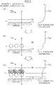
- a planar carrier with openings is disposed in an atmosphere of a moist air outside of the heat exchanger HX.
- the heat exchanger HX includes the thickness t and an outer surface of the heat exchanger HX forms a heat exchange surface S by flowing coolant with temperature of Tc inside of the heat exchanger HX.
- Tin of the moist air flowing along the cooling surface constitutes a temperature distribution in which a slow slope is formed within a temperature boundary layer BL formed based on the surface of the heat exchange surface S to a low Tout of the cooling surface.
- the following explanation is under the condition that the temperature of the air is between 0°C and -40°C.
- Such floating condensed droplets PI fall down and accumulate to form a group of droplets on the surface of the carrier C.
- the group of droplets grows by a coalescence of the droplets PI newly falling down and accumulating, or by water vapor being condensed in the atmosphere.
- the droplets are super-cooled in many cases, but when they grow up to 100 ⁇ m, a super-cooled state is lost, so that a frozen ice surface is formed.
- water vapor begins to sublimate to the frozen ice surface, so that frost crystals P4 are rapidly formed. Since the openings O are closed by the formation of the frost, the frost with air-passage characteristics grow thick.
- the water vapor in the moist air grows into the frost crystals P4, so that the amount of the water vapor reaching the heat exchange surface S through the carrier C decreases due to the water vapor being caught by the frost crystals P4, whereby the growth of the frost on the heat exchange surface S is halted.
- the amount of heat transfer is gradually decreased due to an increase of a thermal resistance of the frost layer, in a case where the frost crystals P4 grow on the heat exchange surface S, a stable heat exchange transfer is attained by such gradual decrease of the amount of the heat transfer being halted.
- a latent heat transfer through the carrier C is conducted due to the fact that the formation of the frost occurs in the same manner as a case of that through the conventional heat exchange surface S, the total amount of heat exchange increases more than that under the growth of the frost only on the heat exchange surface S.
- the thickness of the temperature boundary layer BL varies in accordance with environmental conditions. Normally, the environmental conditions include the ambient temperature and the flow of fluid, however, an explanation about such conditions are omitted here. What is explained about here is a case how the frost layer grows on the surface of the carrier C within a temperature boundary layer BL in Fig.1 within which nothing exists as shown in Fig. 2(A) . As shown in Fig. 2(B) , the thin temperature boundary layer BL in Fig. 2(A) becomes thick by the carrier C being disposed therewithin. In addition, as shown in Fig. 2(C) , the more the frost grows, the thicker the temperature boundary layer BL becomes.
- the frost may grow within a constant temperature boundary layer BL within which nothing exists by the carrier C being disposed therewithin, even if the thickness of the temperature boundary layer BL is very thin, the temperature boundary layer BL becomes thick under the condition that the heat conduction ratio of the carrier C is higher than that of air. This follows that it is considered to be feasible to vary and thicken the thickness of the temperature boundary layer BL by disposing at least a portion of the carrier C within the temperature boundary layer BL, so that there is considered to be much room for utilizing the above-described phenomenon.
- a condition of water vapor in an atmosphere corresponds to a water-saturated atmosphere (including super-saturated state) under air temperature higher than 0°C (zone A)
- water droplets are generated by water vapor being condensed to condensation nuclei in an atmosphere, and then, falls and accumulates on the cooling surface, whereby water vapor is condensed to such accumulated water droplets by a repetition of the above growth and combining into one process to form into big droplets.
- a gravity force exerting on such big droplets exceeds an adhesion force between the big droplets and the cooling surface, the big droplets flows (falls) down on the cooling surface.
- a condition of water vapor in an atmosphere corresponds to the water-saturated atmosphere (including super-saturated state) under air temperature between 0°C and -40°C (zone C)
- super-cooled water droplets are generated by the water vapor being condensed to condensation nuclei in an atmosphere, and then, fall and accumulate on the cooling surface, whereby the super-cooled water droplets grow to be joined to each other, and then, become frozen, and as a result, the water vapor sublimates to the frozen ice particles to cause the formation of frost.
- a condition of water vapor in an atmosphere corresponds to an ice super-saturated atmosphere and does not correspond to the water-saturated atmosphere under air temperature between 0°C and -40°C(zone B)
- ice crystals are generated by water vapor being sublimated to sublimation nuclei in the atmosphere, and then, falls and accumulates on the cooling surface, whereby water vapor are sublimated to such accumulated ice crystals to cause the formation of frost.
- the water vapor in the atmosphere corresponds to the water-saturated atmosphere (including super-saturated state) under the condition that the air temperature is below -40°C (zone D)
- the water vapor is caused to condensate to the condensation nuclei in the atmosphere to immediately form into frozen particles, and then, frozen particles having fallen and accumulated on the cooling surface to form frost in a powder form.
- the water vapor in the atmosphere corresponds to the ice super-saturated state and does not correspond to the water-saturated state under the condition that the air temperature is below -40°C(zone E)
- the water vapor is caused to sublimate to sublimation nuclei in the atmosphere to immediately form into ice crystals, and then, the water vapor sublimates to ice crystals having fallen and accumulated on the cooling surface to form frost.
- the above explanation is based on the assumption that the condensation nuclei or the sublimation nuclei exist in the atmosphere within the temperature boundary layer BL near the cooling surface.
- the condensation nuclei or the sublimation nuclei also exist on the heat exchange surface S, the condensation or the sublimation phenomenon can directly occur on the heat exchange surface S. This follows that, even if the super-saturated phenomenon does not occur in the air, the condensation or the sublimation phenomenon can occur on the heat exchange surface S, only if the condition of the heat exchange surface S corresponds to the surroundings.
- the condensation or the sublimation phenomenon can occur only on the surface of the carrier C, so long as the surface of the carrier C corresponds to the super-saturated state.
- the condensed droplets PI grow into big super-cooled water droplets P3 by a repetition of the above joint, and the big super-cooled water droplets P3 becomes frozen particles.
- Fig.4 (D) water vapor in the air sublimates to the frozen particles, so that the frost begins to grow. Since a rapid growth of the frost on the surface of the carrier C begins, water vapor is caught by the surface of the carrier C, so that the amount of water vapor flowing into the atmosphere on the heat exchange surface S decreases, whereby the super-saturated phenomenon is mitigated.
- a portion of a flow of the fluid is guided to the side of the carrier C to promote the flow of the fluid passing thorough the openings O of the carrier C, whereby the formation of the frost on the heat exchange surface S and the heat transfer through the heat exchange surface S can be promoted.
- the structure of the carrier C and the heat transfer promoter N in Fig. 5(A) is constituted only by the carrier C.
- a plurality of the normal planar carriers C are separated from each other in the flow direction in such a way that only a portion at the upstream side is disposed outside of the temperature boundary layer.
- the carrier C may be sized in such a way that condensed water droplets accumulates to form a group of the super-cooled water droplets P3 and may have any cross section shape.
- the opening O may be sized in such a way that the frost layer having grown on the carrier C closes the opening O at the growing stage.
- the opening O between the adjacent carriers C may be blocked by the growth of the frost on the adjacent carriers C.
- the depth of the carrier C may be any, so long as a space between the carrier C and the heat exchange surface S is kept.
- the carrier C is provided on the heat exchange surface S, since an area for the sensible heat exchange through the heat exchange surface S decreases, it is considered to be important that the carrier C is kept away from the heat exchange surface S in a case where the latent heat exchange and the sensible heat exchange are intended to be separated from each other by means of the carrier C.
- the concrete explanation of the heat exchange surface S is omitted here, but, needless to say, the configuration of the heat exchanger HX is selected so as to prevent such an invasion of the water vapor.
- the cross sectional shapes of the carrier C is shown in Figs. 6(A), 6(B) , and 6(C) .
- Any cross sectional shape of the carrier C can be adopted, as shown in Figs. 6(A), 6(B) , and 6(C) .
- the carrier C includes the openings O, the openings O can be formed by a mechanical cutting operation, an electric discharge machining, a sandblasting method, an etching method, etc., or by a pressing machining. Any method can be adopted.
- a wire in a meshed form such as a metal mesh, or a punching metal, a metal lath (expand metal) can be utilized.
- the width of the carrier C is between 100 ⁇ m and 2000 ⁇ m
- the width L of the opening O is between 100 ⁇ m and 1000 ⁇ m
- the depth between the surface of the carrier C and the heat exchange surface S is above 100 ⁇ m .
- the carrier C in a non-woven form can be adopted, as shown in Fig.7 (A) . According to such a non-woven carrier C, it is technically advantageous to attain a sufficient function without providing gaps on the heat exchange surface S.
- a portion of the carrier C outside the temperature boundary layer BL can be functioned as the heat transfer promoter N.
- the treatment of the frost differs in accordance with "the preservation of the heat exchange surface S " ,” the utilization of the frost " and “the separation of the latent heat exchange and the sensible heat exchange "
- the target of each of "the preservation of the heat exchange surface S " and " the separation of the latent heat exchange and the sensible heat exchange” is the heat exchange surface S itself or to exchange heat through the heat exchange surface S and the surface of the carrier C, and has nothing to do with the treatment of the frost itself.
- defrosting methods hot gas, water sprinkling, off-cycle defrosting, an electrical heater, brine sprinkling, etc.
- a new idea of an utilization of jet flow by an air nozzle, or a mechanical process by using a brush can be adopted.
- the technique of vibrating the carrier C also can be adopted.
- the carrier C on which the frost has grown with time is replaced by a new carrier C on which no frost is formed, and the replaced carrier C with frost is utilized on the spot, or moved to a place where the frost is peeled off from the surface of the carrier C by the physical method such as the jet flow, the vibration, or the mechanical method such as the brush to be utilized for a certain application.
- the carrier C with frost can be utilized as it is, in accordance with applications.
- the carrier C may be replaced, since the frost needs to be treated highly efficiently due to the formation of the frost on the surface of the carrier C in order to maintain the high efficiency of the latent heat exchange.
- a second embodiment of the present invention is now explained about, with reference to Fig.8 .
- the technical feature of this embodiment lies in the fact that the relationship between the carrier C and the heat exchange surface S under the dropwise condensation state is specified.
- the heat exchange surface S With respect to the relationship between the carrier C and the heat exchange surface S under the dropwise condensation phenomenon occurring at the temperature above 0 °C, the heat exchange surface S is oriented to be vertical. This vertical orientation is needed in order for the condensed droplets P1 to drop by gravity. As shown in Fig.8 , a general technical problem of the condensation phenomena on the heat exchange surface S is the decrease of the heat transfer through the heat exchange surface S due to the formation of a water membrane on the heat exchange surface S caused by a surface tension of the condensed droplets P1.
- a good heat exchange can be maintained without the formation of such a water membrane by disposing the carrier C within the temperature boundary layer BL of the heat exchange surface S so as to treat the condensed droplets PI on the surface of the carrier C to drop them by gravity.
- the heat exchange can be improved, as compared with a case of the heat exchange only on the heat exchange surface S.
- the generation of dew can be caused to improve the heat transfer based on the condensation by effecting the water repellent finishing on the surface of the carrier C, while at the same time, a good condensation phenomena can be caused, since the condensed droplets with small diameters can drop by gravity.
- the plugging of the opening O by the condensed droplets can be prevented.
- the size of the opening O needs to be smaller than that is needed for the formation of the frost, since a secondary growth of the frost so as to plug the opening O is not expected to occur, unlike the first embodiment, so that the water droplets tend to easily reach the heat exchange surface S through the opening O.
- the positive generation of dew on the heat exchange surface S is halted, since the condensation on the surface of the carrier C decreases the water vapor in the atmosphere, so that the water droplets having passed through the opening O in the atmosphere of the space between the heat exchange surface S and the carrier C are reduced.
- the inventors confirmed the effectiveness of the present invention by carrying out an experiment concerning the suppression of the frost crystals P4 in which a micro object is disposed within the temperature boundary layer to utilize the condensation and the solidification occurring within the temperature boundary layer to grow the frost crystals P4 within temperature boundary layer to control their growth, with a view to realizing a phenomenon in which the frost crystals P4 is not adhered on the heat exchange surface S.
- An experimental small chamber a thermostatic system for maintaining the temperature and the humidity in the experimental small chamber constant, a measurement system, an observation system, and a heat transfer section are provided.
- the temperature and the humidity in the experimental small chamber are controlled by an air conditioner, a humidifier, a dehumidifier and a heater, while the temperature and the humidity in the experimental chamber are measured by a Asman wet-and-dry bulb thermometer disposed in the experimental small chamber.
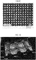
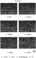
- Figs.9 and 10 show a photograph and a three-dimensional image of the metal mesh used in this research.
- the metal mesh is planar-woven with 100 ⁇ m diameter made of steel (SUS304) wires and has an aperture of 150 ⁇ m.
- a space is provided between the heat exchange surface S and the metal mesh and the micro object is disposed within the temperature boundary layer.
- the frosting phenomenon is a transient process because the frost layer changes with time. It should be noted that the present experiments were conducted under the condition that the heat exchange surface temperature changed with time.
- the heat flux qf [W/m2] on the surface was obtained by using the recorded temperature and the lumped-thermal-mass approximation, which is possible because the heat exchange surface is made of oxygen-free copper.
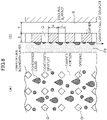
- Fig. 11 shows a schematic diagram of the heat exchange surface.
- the heat exchange surface consists of 5 oxygen-free cupper plates, each 40mm wide, 18mm long, and 10mm thick.
- the heat exchange surface is flat and has been polished sufficiently.
- the inventors paid attention to the size of the super-cooled water droplets P3 to vary the configuration of the heat exchange surface S by artificially providing fine concave and convex surfaces with several hundred u m on the heat exchange surface S, and as a result, succeeded in preventing the frost crystals P4 from growing on the heat exchange surface S ( a portion of the heat exchange surface S).
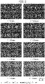
- Fig.12 shows a typical example of an observation result of the process of the formation and the growth of the frost crystals P4, in a case where fine grooves in a mesh form are machined on the cooling surface.
- the super-cooled water droplets P3 are generated on the convex surface to be coalesced into big droplets with time after the start of the experiment.
- the super-cooled water droplets P3 having repeatedly coalesced becomes a single droplet on the square convex surface to form into a protruded plateau ice after the super-cooled state is lost.
- the super-cooled state lasts up to fifteen minutes after the start of the experiment, based on the fact that a white ring by a light is confirmed on the central portion.
- a metal mesh with a size substantially same as the convex portion in Fig.12 is selected as the micro object disposed within the temperature boundary layer and is rested on the heat exchange surface S.
- Fig. 13 shows an observation result of the formation of the frost crystals P4 in a case where the metal mesh in Fig.10 is rested on the flat heat exchange surface S.
- the observation was carried out from above. According to the observation, it was confirmed that the super-cooled water droplets P3 are generated on the heat exchange surface S and the surface of the metal mesh, and that a plurality of the frost crystals P4 were generated from the protruded plateau ice on the metal mesh after the loss of the super-cooled state. On the other hand, the frost crystals P4 were not confirmed on the heat exchange surface S.
- Fig.14 is a sketch illustrating the mechanism of the formation and the growth of the frost crystals P4.
- the growing speed of the frost crystals P4 is the fastest at the convex portion of the metal mesh, while spherical ice is adhered on the heat exchange surface S after the loss of the super-cooled state, however, the frost crystals P4 was not formed due to the size of the ice being below 150 ⁇ m.
- Fig.15 shows an observation result from side
- Fig.16 is a sketch drafted based on the observation result. As shown in Figs. 15 and 16 , it was confirmed that the frost crystals P4 are formed to grow on the surface of the metal mesh, but that the frost crystals P4 are not formed to grow on the heat exchange surface S.
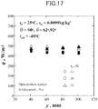
- Fig.17 shows a relationship between a heat flux and a temperature of the heat exchange surface S.
- the temperature of the heat exchange surface S in a case where the metal mesh is attached is not a temperature of the surface of the metal mesh, but that of the surface of the heat transfer portion made of oxygen-free copper.
- Fig. 17 it was confirmed that the metal mesh does not influence much on the heat flux, since there is not a peculiar difference of the heat flux between the two cases.
- Fig.18 shows a temperature distribution within the temperature boundary layer on the basis of the position of the surface of the frost layer.
- the thickness of the frost layer was measured based on the surface of the frost layer.
- the heat exchange surface S on which the frost crystals P4 are adhered is oriented to be horizontally upward.
- the heat exchange surface S is an end face of a square pillar made of oxygen-free copper with 50mm wide, 50mm long, and a copper plate with the thickness of 1mm is adhered to the end face by epoxy adhesion to form the heat exchange surface.
- the temperature of the surface of the heat exchange surface S is measured by adhering CA thermocouple (diameter :100 ⁇ m) to the underside of the copper plate.
- the temperature of the surface of frost layer is measured by a thermocouple.
- the thermocouple is attached in an arc form to a support portion made of Bakelight with a thermal insulating effect to be mounted on a traverse device horizontally and vertically movable relative to the heat exchange surface S through a metal supporting rod.
- the measurement was conducted in such a way that the temperature within the temperature boundary layer BL is measured by a digital scope, while the temperature of the moist air portion at the position where the thickness of the frost layer is measured is measured as a frost layer surface temperature.
- the heat transfer portion the side of which is thermally insulated by adhesive made of foamed urethane and silicone was disposed in the experimental small chamber made of Dan puller. It was confirmed that the frost layer surface temperature was below 0°C, so that the frost crystals P4 grew, in a case where the metal mesh is provided.
- dehumidification was carried out within the temperature boundary layer BL by disposing the planar carrier C or the mesh carrier C within the temperature boundary layer BL determined in accordance with the temperature of the exchange surface S, the planar carrier C or the mesh does not need to be disposed, so long as dehumidification is secured within the temperature boundary layer BL.
- the mesh carrier C is disposed within the temperature boundary layer BL determined in accordance with the temperature of the exchange surface S, and then, is replaced, other physical object by which the formation of the frost is promoted may be disposed, so long as the formation of the frost or the dew on the heat exchange surface S can be prevented.
Description
- The present invention relates to a operating method to preserve a heat exchange surface. More specifically, the present invention relates to a operating method to preserve a heat exchange surface which is capable of providing the maintenance-free heat exchange surface by preventing the transfer of mass on a heat exchange surface that has a large temperature differential with the surroundings and a method of cooling moist air which is capable of highly efficiently and stably cooling moist air, in a case where moist air is cooled through the heat exchange surface, or in a case where heat is adsorbed from moist air with temperature below 0°C, within the temperature boundary layer.
- In a case where heat is exchanged between a fluid and a dry air through a heat exchange surface, a dropwise condensation, a frost formation, or a freezing frequently occurs on a side of the heat exchange surface contacting air under the condition that a temperature of the heat exchange surface (referred to as a cooling surface hereinafter) is lower than that of air.
- Here, conditions for occurrence of the frost formation, or the condensation phenomenon is explained about, with reference to
Fig.3 . If a condition of water vapor in an atmosphere corresponds to a water-saturated atmosphere ( including super-saturated state) under air temperature higher than 0°C, water droplets are generated by water vapor being condensed to condensation nuclei in an atmosphere, and then, falls and accumulates on the cooling surface, whereby water vapor is condensed to such accumulated water droplets by a repetition of the above growth and combining into one process to form into big droplets. When a gravity force exerting on such big droplets exceeds an adhesion force between the big droplets and the cooling surface, the big droplets flows (falls) down on the cooling surface. - If a condition of water vapor in an atmosphere corresponds to the water-saturated atmosphere ( including super-saturated state) under air temperature between 0°C and -40°C, super-cooled water droplets are generated by the water vapor being condensed to condensation nuclei in an atmosphere, and then, fall and accumulate on the cooling surface, whereby the super-cooled water droplets grow to be joined to each other, and then, become frozen, and as a result, the water vapor sublimates to the frozen ice particles to cause the formation of frost.
- If a condition of water vapor in an atmosphere corresponds to an ice super-saturated atmosphere and does not correspond to the water-saturated atmosphere under air temperature between 0°C and -40°C, ice crystals are generated by water vapor being sublimated to sublimation nuclei in the atmosphere, and then, fall and accumulate on the cooling surface, whereby water vapor are sublimated to such accumulated ice crystals to cause the formation of frost.
- Now, the condensation or the sublimation phenomenon is explained about in more detail. When a moist air is cooled, water vapor in the atmosphere becomes a super-saturated state (refer to as a water super-saturated state) in which the water vapor cannot maintain its gas state any longer, so that the condensation phenomenon sets in. An air temperature at this state is referred to as dew point. In addition, in a case where an ambient temperature is below 0°C, the water vapor can become either an ice super-saturated state or a water super-saturated state. This is because the amount of super-saturated water vapor under the ice state is smaller than that under the water state, the ice super-saturated phenomenon precedes over the water super-saturated phenomenon, so that the water vapor over the amount of the super-saturated water vapor emerges as ice crystals (referred to as ice crystal hereinafter) by sublimating to the ice crystal nuclei in the atmosphere. An air temperature at the stage is referred to as a freezing point. In this connection, if the water vapor is further cooled under a low temperature to become a water super-saturated condition where a condensation phenomenon sets in, like the case of the air temperature above 0°C, however, under the condition of the air temperature is below -40°C, the condensed droplets immediately become the super-cooled droplets without being frozen. An air temperature at the stage is also referred to as dew point, like a case of the air temperature above 0°C. The super-cooled droplets stochastically become frozen with time. Since the water vapor pressure of the ice is lower than that of the surroundings, water vapor positively sublimates to such an icy surface, whereby frost crystals P4 rapidly start to grow.
- In addition, in a case where a condition of water vapor in the atmosphere corresponds to a water-saturated atmosphere ( including super-saturated state) under the condition that the air temperature is below -40°C, the water vapor is caused to condensate to the condensation nuclei in the atmosphere to immediately form into frozen particles, and then, frozen particles having fallen and accumulated on the cooling surface to form frost in a powder form. In this connection, if the temperature of the cooling surface is below -40°C, but the air temperature in the atmosphere is above -40°C warmer than the cooling surface, the accumulated powder frost gets thick, and if the temperature of the surface of the frost layer becomes above -40°C due to that it is exposed to the atmosphere, water vapor sublimates to the frost to cause the formation and the growth of the frost.
- Further, in a case where a condition of water vapor in the atmosphere corresponds to an ice super-saturated atmosphere and does not correspond to the water-saturated atmosphere under the condition that the air temperature is below -40°C, the water vapor is caused to sublimate to sublimation nuclei in the atmosphere to immediately form into ice crystals, and then, the water vapor sublimates to ice crystals having fallen and accumulated on the cooling surface to form frost.
- In this connection, the above explanation is based on the assumption that the condensation nuclei or the sublimation nuclei exist in the atmosphere within the temperature boundary layer near the cooling surface. However, since the condensation nuclei or the sublimation nuclei also exist on the cooling surface, the condensation or the sublimation phenomenon can directly occur on the cooling surface. This follows that, even if the super-saturated phenomenon does not occur in the air, the condensation or the sublimation phenomenon can occur on the cooling surface, only if the condition of the cooling surface corresponds to the surroundings.
- The dew is a cause of a deterioration of a hygienic aspect such as generation of fungus, the corrosion, the electrical leak, or a smear of the heat exchange surface S, while the formation of the frost or the freezing is a cause for a decrease of the amount of heat exchange along with a thermal resistant layer caused by a liquid membrane on the heat exchange surface S upon the generation of dew, since a frost layer or an ice layer forms another thermal resistant layer upon the heat exchange and its physical thickness hinders an air-passage. Needless to say, if the frost or the ice melts, the problem same as the case of the dropwise condensation generating dew occurs. Such being the case, conventionally, various kinds of technologies for defrosting or dehumidifying the heat exchange surface S has been adopted.
- In this connection, a patent publication 1 discloses an agent for adjusting a humidity using multi-cellular material, or an agent for preventing dew.
- More specifically, the agent for adjusting a humidity using multi-cellular material, or the agent for preventing dew, are constituted by agglomerating fine particles at a nano level without a gap between the particles being lost each of which particle does not include multi-cellular characteristics. In other words, multi-cellular material including an empty hole at a nano level between fine particles is adopted, so that a multi-cellular structure including a distribution of fine holes in which a diameter of fine hole ranges between 1nm and 10 nm. Based on a capillary condensation theory by Kevin, the amount of adsorbing water vapor increases at the range of relative humidity of between 75% and 93%. More concretely, an isothermic adsorbing curve rises near about 80%, and the amount of adsorbing water vapor between relative humidity of 75% and 93% is about 12 mass%, so that water vapor adsorbed between the relative humidity of 75% and 93% is emitted at the
relative humidity 70%, whereby an ability for preventing dew is recovered, under the isothermic adsorbing curve. - By such an agent for adjusting a humidity using multi-cellular material, or an agent for preventing dew, water vapor in moist air which causes dew is adsorbed, while at the same time, the ability for preventing dew can be recovered by adsorbed water vapor being emitted, so that the agent can be repeatedly used. In addition, water vapor in the moist air can be caught due to the diameter of the fine hole being between 1 nm and 10nm. However, in a case where super-cooled condensed droplets are generated in the moist air under the condition that the temperature of moist air is below 0°C, humidity cannot be adjusted, or the generation of dew cannot be prevented by catching super-cooled condensed droplets, since the diameter of super-cooled condensed droplets is at least 1 µ m.
- In this respect, it has been desired to realize a method of preserving the maintenance-free heat exchange surface by preventing mass transfer on the heat exchange surface whose temperature largely differs from the surroundings, in case of a device for cooling moist air for a refrigerator processing moist air with temperature of below 0°C.
- On the other hand, in a case where moist air is cooled to below 0°C by a device for cooling moist air, in particular, or in a case where heat is adsorbed from the moist air by a LNG vaporizer, not dew, but frost formation or freezing can occur on the cooling surface which constitutes the heat exchange surface.
- In such a case, a frost layer becomes a thermal resistant layer, because of its low thermal conductivity, or grown frost can block a passage of the moist air which is a target to be cooled, so that an efficiency of exchanging heat can decrease, on the whole.
- In this respect, a patent publication 2, which is considered to be closest prior art regarding the subject-matter of claim 7, discloses a heat exchanger which can utilize a solidification heat, while at the same time, can continuously operate for a long time by making it easy to mechanically remove frost.
- More specifically, this heat exchanger is the one which can adsorb heat from the moist air and includes fine concave and convex portions on its surface. On an upper surface of the convex portion, a flat portion with a minimum width being between 100 µ m and 500 µ m is formed, and a minimum width of the concave portion is between 100 µ m and 1000 µ m. Frost crystals P4 can vertically grow on the flat portion of the upper surface of the convex portion, by providing the convex and concave portions on the surface of the heat exchanger. Since the frost crystals P4 grow on the convex portions, while a gap is formed around the concave portions, the frost crystals P4 in a comb-teeth form are formed. Such a comb-teeth form is structurally weak, the frost crystals P4 can be readily removed by a mechanical device such as a brush, a scraper, etc.. This allow for the heat exchanger to be continuously operated for a long time, while at the same time to utilize the solidification heat.
- Further, a patent publication 3 discloses a member for preventing a frost formation. More specifically, in this member, a water repellant portion and a hydrophilic portion whose hydrophilic property is higher than the water repellant portion are formed in a predetermined pattern.
- A frost is difficult to form on the water repellant portion due to its high water repellant property, while a frost is easy to form on the hydrophilic portion. Accordingly, a frost on the hydrophilic portion grows until its size becomes the one which cannot resist on an air flow, and then, it collapses, since a frost cannot grow on the water repellant portion, while a frost can largely grow on the hydrophilic portion. Such a growth and a collapse of frost is repeated.
- As described above, a frost formation can be suppressed by promoting a repetition of the growth and the collapse of frost by means of the formation of the water repellant portion and the hydrophilic portion in a predetermined pattern.
- However, in a case where a frost formation is prevented by the process or the treatment of the heat exchange surface, as disclosed by the patent publications 2 and 3, a frost formation can inevitably occur with time, so that a state in which a frost is not formed cannot be maintained for a long time.
- On the other hand, since the situation in which frost is formed can vary, in accordance with the conditions on the temperature and the humidity of the coolant or the moist air, or the variation of the state in which the moist air flows, it is difficult to meet the variation of such conditions.
- Further, although it is possible to accelerate a sensible heat exchange, since the frost formation of the moist air on the cooling surface can be prevented, a latent heat exchange (solidification heat) involved by change of phase of water vapor is excluded, so that the method of exchanging heat in total is not necessarily improved.
- In this connection, a patent publication 4, which is considered as closest prior art for
claims 1 and 10, discloses a device for reducing the frost formation on a cooler. More specifically, this device is disposed near the heat exchanger for cooling including a heat transfer tube and a plurality of fins each of which is attached on the heat transfer tube, and includes a jetting means including a plurality of nozzles disposed perpendicular, or parallel to the direction in which planes of the fins extend, and a driving means for driving the jetting means in a reciprocal manner. The jetting means moves parallel or perpendicular to the direction in which planes of the fins extend to jet the moist air. The plurality of nozzles arranged in one row and move parallel or perpendicular to the direction in which planes of the fins extend to jet the moist air. The moist air is jetted to the entire area of the fins of the heat exchanger for cooling by discharging the moist air along the surface of the fins of the cooler, so that water droplets in a super-cooled state before they are formed into frosts and the frozen frost can be removed by exerting a fluid pressure on the frost formed on the surface of the fin, since the frost formation can be reduced by a small amount of the moist air without halting the operation of the cooling device, the efficiency of the cooling operation can be maintained at a high level, and the cost for preventing the frost formation and removing the frost can be reduced. - However, the device for reducing frost formation for the cooler forcibly removes the frost by jetting moist air to the frost formed on the surface of the fin, so that it neither prevents the frost formation, nor utilizes the frost formed on the surface of the fin. In addition, a maintenance has to be carried out in such a way that the formed frost does not block an opening of the nozzle, since the device for reducing frost formation is disposed near the heat exchanger for cooling.
- In this respect,
patent publications 5, which is considered closest prior art for claim 2, and 6 disclose a net for removing iced frost or iced snow which removes snow from a wind-shield of an automobile, in a case where ice or frost is adhered to the wind-shield of the automobile, or in a case where snow is accumulated thereon. - More specifically, this net for removing iced frost or iced snow is constituted by wires with a predetermined width arranged in a planar mesh with a predetermined width and is directly laid on the wind-shield of the automobile.
- By such a net for removing iced frost or iced snow, ice, frost, or snow accumulated on the wind-shield through opening portion of the mesh can be removed by pulling or removing the net which has become in one piece with the ice, or the frost formed in the opening portions of the mesh, or the snow accumulated in the opening portions of the mesh.
- Such being the case, since the ice, frost, or snow to be removed and the net become in one piece, the width of the wire is determined in accordance with the thickness of the formed ice, frost, or snow, while the width of the mesh is determined in accordance with the adhesion force of the wires to the formed ice, frost, or snow.
- In more detail, if the thickness of the ice, frost, or the snow is about 3 millimeter, the width of the wire is set to be between 2 millimeter and 6 millimeter, while the width of the mesh is set to be between 10 millimeter and 50 millimeter (patent publication 5). If the thickness of the ice, frost, or the snow is below 2 millimeter, the width of the wire is set to be between 0.5 millimeter and 2 millimeter, while the width of the mesh is set to be between 1 millimeter and 10 millimeter (patent publication 6).
- In either of the above cases, the net for removing iced frost or iced snow merely removes iced frost or iced snow by pulling or removing the net which has been simply formed and has become in one piece with the iced frost or iced snow formed on the wind-shield of the automobile, like a case where the frost is not formed on the wind-shield of the automobile which is under a roof of a parking facility.
- As described above, in the conventional heat exchange surface, the heat exchange surface cannot be preserved for a long time, and a maintenance of the heat exchange operation on the cooling surface becomes difficult with time.
- In short, a technical idea in which the condensation or frost formation phenomenon is caused separately from the cooling surface is neither suggested nor disclosed in the conventional heat exchange surface.
- Patent Publication 1:
Japanese Patent Publication No. 4599592 - Patent Publication 2:
Japanese Patent Laid-open Publication 2012-82989 - Patent Publication 3:
Japanese Patent Laid-open Publication 2003-240487 - Patent Publication 4:
Japanese Patent Laid-open Publication 2008-64326 - Patent Publication 5:
Japanese Utility Model Publication No. 3169488 - Patent Publication 6:
Japanese Patent Publication No. 4224121 - Furthermore,
documents DE 10 2011 102 216 A1 ,EP 1 318 371 A2 ,DE 203 11 452 U1 ,EP 1 219 912 A1 andDE 10 2008 041 480 A1DE2510755A is considered as being the closest prior art. - In view of the technical problem described above, it is an object of the present invention to provide an operating method to preserve a heat exchange surface which is capable of making the heat exchange surface on a maintenance-free basis by preventing mass transfer on the heat exchange surface the temperature of which largely differs from its surroundings.
- In the present invention, after an attention is paid to the condensation, the frost formation, or the freezing phenomena occurring on the heat exchange surface, an innovative idea in which the condensation, the frost formation, or the freezing phenomena is caused to occur separately from the cooling surface is devised.
- In order to attain the above object, a method of preserving the heat exchange surface according to the present invention is configured according to claim 1.
- In this connection, the technical meaning of the freezing point is to be defined in this specification as follows. When a moist air is cooled, water vapor in the atmosphere becomes a super-saturated state (refer to as a water super-saturated state) in which the water vapor cannot maintain its gas state any longer, so that the condensation phenomenon sets in. An air temperature at this state is referred to as dew point. In addition, in a case where an ambient temperature is below 0°C, the water vapor can become either an ice super-saturated state or a water super-saturated state. This is because the amount of super-saturated water vapor under the ice state is smaller than that under the water state, the ice super-saturated phenomenon precedes over the water super-saturated phenomenon, so that the water vapor over the amount of the super-saturated water vapor emerges as ice crystals (referred to as ice crystal hereinafter) by sublimating to the ice crystal nuclei in the atmosphere. An air temperature at the stage is referred to as a freezing point. In this connection, if the water vapor is further cooled under a low temperature to become a water super-saturated condition where a condensation phenomenon sets in like the case of the air temperature above 0°C, however, under the condition of the air temperature is below -40°C, the condensed droplets immediately become the super-cooled droplets without being frozen. An air temperature at the stage is also referred to as dew point, like a case of the air temperature above 0°C.
- According to the above configuration, in the heat exchange surface for cooling moist air contacting the heat exchange surface, within a temperature boundary layer determined in accordance with the temperature of the heat exchange surface and the air flow thereon, in a case where the temperature is below the dew point under the condition that the temperature of air in the temperature boundary layer is above 0 °C, or in a case where the temperature is below the freezing point under the condition that the temperature of air in the temperature boundary layer is below 0 °C, when the moist air is cooled to below 0°C through the heat exchange surface, or when heat is absorbed form the moist air the temperature of which is below 0°C, a carrier including the heat conduction ratio higher than that of moist air is provided to be disposed opposed to the heat exchange surface and within the temperature boundary layer, so that moist air is dehumidified by condensing water vapor in the moist air, or by causing it to form into frost, on the surface of the carrier, whereby the amount of water vapor in the moist air reaching the heat exchange surface is reduced, and as a result, highly efficient and stable cooling on the heat exchange surface can be effected without the frost growing into a thermal resistant layer by suppressing the dropwise condensation generating dew or the frost formation on the heat exchange surface.
- According to this invention, condensing water vapor in the moist air takes place on the surface of the carrier opposed to the heat exchange surface whose temperature is below the dew point of the moist air to flow the condensed liquid down along the surface of the carrier, under the condition that the temperature of the moist air within the temperature boundary layer determined in accordance with the temperature of the heat exchange surface and the air flow thereon is above 0°C.
- Further, sublimating water vapor in the moist air to a surface of ice formed by condensation, super-cooling, takes place on the surface of the carrier opposed to the heat exchange surface whose temperature is below the dew point of the moist air to cause it to grow into frost crystals P4, whereby the moist air is dehumidified to suppress the frost formation on the heat exchange surface, under the condition that the temperature of the moist air within the temperature boundary layer determined in accordance with the temperature of the heat exchange surface and the air flow thereon is between 0°C and -40°C.
- Still further, it is preferred to further include a step of growing the water vapors in the moist air into ice crystals formed by condensing and solidifying (freezing), on the surface of the carrier opposed to the heat exchange surface whose temperature is below the dew point of the moist air to cause it to grow into ice crystals, whereby the moist air is dehumidified to suppress the frost formation on the heat exchange surface, under the condition that the temperature of the moist air within the temperature boundary layer determined in accordance with the temperature of the heat exchange surface and the air flow thereon is below -40°C.
- More still further, it is preferred to further include a step of sublimating water vapor in the moist air, on the surface of the carrier opposed to the heat exchange surface whose temperature is above the dew point of the moist air and below the freezing point to grow it into frost crystals P4, whereby the moist air is dehumidified to suppress the frost formation on the heat exchange surface, under the condition that the temperature of the moist air within the temperature boundary layer determined in accordance with the temperature of the heat exchange surface and the air flow thereon is below 0°C.
- It is preferred that the carrier is shaped to be a planar structure with a fixed form or formless cross section in which non-opening portions each of which including a predetermined width and openings are arranged in an alternate manner and is disposed away from the heat exchange surface with a predetermined distance.
- Further, it is preferred that the planar carrier is shaped to be a mesh-form including openings with a predetermined widths and wires with predetermined widths and thicknesses.
- Still further, it is preferred that the width of the planar carrier is between 100 µ m and 2000 µ m, the width of the opening is between 100 µ m and 1000 µ m, and the distance between the surface of the carrier at the side of the temperature boundary layer and the heat exchange surface is above 100 µ m.
- Still further, it is preferred that the carrier is shaped to be a three-dimensional structure with voids constituted by fibers with predetermined lengths and a fixed form or formless cross section being superimposed in a non-woven manner.
- Still further, it is preferred that the planar carriers are disposed along the heat exchange surface to be separated from each other so as to define a gap of an opening between adjacent carriers and that a portion of the carriers upstream of the heat exchange surface is disposed in a main air flow outside the temperature boundary layer, whereby heat transfer through the heat exchange surface is promoted by guiding the air flow inside the carriers within the temperature boundary layer.
- Still further, it is preferred that the three-dimensional carriers are thickened in such a way that a portion of the carrier is disposed in the main air flow outside the temperature boundary layer, whereby heat transfer through the heat exchange surface is promoted by guiding the air flow inside the carrier within the temperature boundary layer.
- Still further, it is preferred that water repellent treatment is carried out on the surface of the carrier to vary the surface condition of the carrier so as to improve the dehumidification performance by the sublimation, or the condensation of the water vapor on the surface of the carrier and so as not to block the openings by the formed liquid.
- Still further, it is preferred that the surface of the carrier is set to possess an adsorption performance to vary the surface condition of the carrier so as to improve the dehumidification performance by the sublimation, or the condensation of the water vapor on the surface of the carrier.
- Still further, it is preferred that the fibers of the carrier is made of high water absorptivity resin to enhance the water absorptivity, water retentivity, and capillary water absorptivity of the carrier to improve the dehumidification performance by the sublimation, or the condensation of the water vapor on the surface of the carrier.
- Still further, it is preferred that the method of cooling moist air through a heat exchange surface according to the present invention includes a step of taking out the carrier with the frost formed thereon at the side of the temperature boundary layer to utilize the frost so as to use the amount of heat of the frost.
- Still further, it is preferred that the method of cooling moist air through a heat exchange surface whose temperature is below 0 °C according to the present invention includes a step of providing the carrier made of material the heat conduction ratio of which is low and disposing the carrier near and within the temperature boundary layer and setting the temperature of the surface of the carrier as high as possible to suppress the amount of the frost growing on the surface of the carrier, whereby a sensible heat exchange through the heat exchange surface as well as a latent heat exchange through the surface of the carrier is carried out.
- According to the above configuration, in the heat exchange surface for cooling moist air contacting the heat exchange surface whose temperature is below 0°C, within the temperature boundary layer determined in accordance with the temperature of the heat exchange surface and the air flow thereon, in a case where the temperature of air in the temperature boundary layer is below the freezing point, when the carrier including the heat conduction ratio higher than that of moist air is provided to be disposed opposed to the heat exchange surface and within the temperature boundary layer, moist air is dehumidified by condensing or sublimating water vapor in the moist air on the surface of the carrier, whereby the amount of water vapor in the moist air reaching the heat exchange surface is reduced, and as a result, highly efficient and stable cooling on the heat exchange surface can be effected without the frost growing into a thermal resistant layer by suppressing the dropwise condensation generating dew or the frost formation on the heat exchange surface, while at the same time, the time period for the frost being saturated on the surface of the carrier is lengthened to delay the deterioration of air-passage characteristics of the moist air, whereby the continuous latent heat exchange through the surface of the carrier is accomplished by providing the carrier made of material the heat conduction ratio of which is low and disposing the carrier near and within the temperature boundary layer and setting the temperature of the surface of the carrier as high as possible to suppress the amount of the frost growing on the surface of the carrier.
- Still further, it is preferred that the method of cooling moist air through a heat exchange surface whose temperature is below 0 °C according to the present invention includes a step of providing the carrier made of material the heat conduction ratio of which is high and disposing the carrier near and within the temperature boundary layer and setting the temperature of the surface of the carrier as low as possible to increase the amount of the frost growing on the surface of the carrier, whereby the sensible heat exchange through the heat exchange surface as well as the latent heat exchange through the surface of the carrier is promoted.
- According to the above configuration, in the heat exchange surface for cooling moist air contacting the heat exchange surface whose temperature is below 0°C, within a temperature boundary layer determined in accordance with the temperature of the heat exchange surface and the air flow thereon, in a case where the temperature of air in the temperature boundary layer is below the freezing point, when the carrier including the heat conduction ratio higher than that of moist air is provided to be disposed opposed to the heat exchange surface and within the temperature boundary layer, moist air is dehumidified by condensing or sublimating water vapor in the moist air on the surface of the carrier, whereby the amount of water vapor in the moist air reaching the heat exchange surface is reduced, and as a result, highly efficient and stable cooling on the heat exchange surface can be effected without the frost growing into a thermal resistant layer by suppressing the dropwise condensation generating dew or the frost formation on the heat exchange surface, while at the same time, the latent heat exchange through the surface of the carrier is promoted by providing the carrier made of material the heat conduction ratio of which is high and disposing the carrier near and within the temperature boundary layer and setting the temperature of the surface of the carrier as low as possible to increase the amount of the frost growing on the surface of the carrier.
- A first embodiment of the present invention is described in detail, with reference to the drawings.
- In the following embodiments, a size, a material, a specific numerical limitation, etc. are only examples for making it easy to grasp the present invention, so that these elements are not intended to limit the present invention, unless explicitly described otherwise, in particular.
- In the following description, with respect to the same elements as those in the following embodiments, an explanation thereabout is omitted by attaching the same reference numbers to those elements.
- With an example of a case where an air is cooled to below 0°C by using coolant by means of an heat exchanger HX, the embodiment of the present invention is explained about, with reference to the drawings.
- As shown in
Fig.1 , a planar carrier with openings is disposed in an atmosphere of a moist air outside of the heat exchanger HX. - The heat exchanger HX includes the thickness t and an outer surface of the heat exchanger HX forms a heat exchange surface S by flowing coolant with temperature of Tc inside of the heat exchanger HX.
- Tin of the moist air flowing along the cooling surface constitutes a temperature distribution in which a slow slope is formed within a temperature boundary layer BL formed based on the surface of the heat exchange surface S to a low Tout of the cooling surface. The following explanation is under the condition that the temperature of the air is between 0°C and -40°C.
- At this stage, in a case where the planar carrier C including openings in the temperature boundary layer BL is formed so as to secure a gap relative to the heat exchange surface S, water vapor in the moist air becomes a saturated state (the temperature of air becomes the dew point) at the opposite side of the heat exchange surface S in the carrier C, due to the lowering of its temperature, so that the condensation occurs in the condensation nuclei in the air.
- Such floating condensed droplets PI fall down and accumulate to form a group of droplets on the surface of the carrier C.
- The group of droplets grows by a coalescence of the droplets PI newly falling down and accumulating, or by water vapor being condensed in the atmosphere.
- The droplets are super-cooled in many cases, but when they grow up to 100 µ m, a super-cooled state is lost, so that a frozen ice surface is formed. At this stage, water vapor begins to sublimate to the frozen ice surface, so that frost crystals P4 are rapidly formed. Since the openings O are closed by the formation of the frost, the frost with air-passage characteristics grow thick. At this stage, the water vapor in the moist air grows into the frost crystals P4, so that the amount of the water vapor reaching the heat exchange surface S through the carrier C decreases due to the water vapor being caught by the frost crystals P4, whereby the growth of the frost on the heat exchange surface S is halted.
- In this state, a sensible heat exchange is stably conducted through the heat exchange surface S by the formation of the frost on the surface of the carrier C disposed within the temperature boundary layer BL.
- Although the amount of heat transfer is gradually decreased due to an increase of a thermal resistance of the frost layer, in a case where the frost crystals P4 grow on the heat exchange surface S, a stable heat exchange transfer is attained by such gradual decrease of the amount of the heat transfer being halted. In addition, since a latent heat transfer through the carrier C is conducted due to the fact that the formation of the frost occurs in the same manner as a case of that through the conventional heat exchange surface S, the total amount of heat exchange increases more than that under the growth of the frost only on the heat exchange surface S.
- Such being the case, a new heat exchange configuration in which the latent heat exchange through the surface of the carrier C and the conventional sensible heat exchange through the heat exchange surface S are separated from each other is attained by an innovative idea in which the carrier C including the openings S is formed within the temperature boundary layer BL of the heat exchange surface S.
- In this connection, with respect to the temperature boundary layer BL described above, the thickness of the temperature boundary layer BL varies in accordance with environmental conditions. Normally, the environmental conditions include the ambient temperature and the flow of fluid, however, an explanation about such conditions are omitted here. What is explained about here is a case how the frost layer grows on the surface of the carrier C within a temperature boundary layer BL in
Fig.1 within which nothing exists as shown inFig. 2(A) . As shown inFig. 2(B) , the thin temperature boundary layer BL inFig. 2(A) becomes thick by the carrier C being disposed therewithin. In addition, as shown inFig. 2(C) , the more the frost grows, the thicker the temperature boundary layer BL becomes. Such being the case, although the frost may grow within a constant temperature boundary layer BL within which nothing exists by the carrier C being disposed therewithin, even if the thickness of the temperature boundary layer BL is very thin, the temperature boundary layer BL becomes thick under the condition that the heat conduction ratio of the carrier C is higher than that of air. This follows that it is considered to be feasible to vary and thicken the thickness of the temperature boundary layer BL by disposing at least a portion of the carrier C within the temperature boundary layer BL, so that there is considered to be much room for utilizing the above-described phenomenon. - Here, conditions for occurrence of the frost formation, or the condensation phenomenon is explained about, with reference to
Fig.3 . If a condition of water vapor in an atmosphere corresponds to a water-saturated atmosphere ( including super-saturated state) under air temperature higher than 0°C (zone A), water droplets are generated by water vapor being condensed to condensation nuclei in an atmosphere, and then, falls and accumulates on the cooling surface, whereby water vapor is condensed to such accumulated water droplets by a repetition of the above growth and combining into one process to form into big droplets. When a gravity force exerting on such big droplets exceeds an adhesion force between the big droplets and the cooling surface, the big droplets flows (falls) down on the cooling surface. - If a condition of water vapor in an atmosphere corresponds to the water-saturated atmosphere ( including super-saturated state) under air temperature between 0°C and -40°C (zone C), super-cooled water droplets are generated by the water vapor being condensed to condensation nuclei in an atmosphere, and then, fall and accumulate on the cooling surface, whereby the super-cooled water droplets grow to be joined to each other, and then, become frozen, and as a result, the water vapor sublimates to the frozen ice particles to cause the formation of frost.
- If a condition of water vapor in an atmosphere corresponds to an ice super-saturated atmosphere and does not correspond to the water-saturated atmosphere under air temperature between 0°C and -40°C(zone B), ice crystals are generated by water vapor being sublimated to sublimation nuclei in the atmosphere, and then, falls and accumulates on the cooling surface, whereby water vapor are sublimated to such accumulated ice crystals to cause the formation of frost.
- Now, the condensation or the sublimation phenomenon is explained about in more detail. When a moist air is cooled, water vapor in the atmosphere becomes a super-saturated state (refer to as a water super-saturated state) in which the water vapor cannot maintain its gas state any longer, so that the condensation phenomenon sets in. An air temperature at this state is referred to as dew point. In addition, in a case where an ambient temperature is below 0°C, the water vapor can become either an ice super-saturated state or a water super-saturated state. This is because the amount of super-saturated water vapor under the ice state is smaller than that under the water state, the ice super-saturated phenomenon precedes over the water super-saturated phenomenon, so that the water vapor over the amount of the super-saturated water vapor emerges as ice crystals (referred to as ice crystal hereinafter) by sublimating to the ice crystal nuclei in the atmosphere. An air temperature at the stage is referred to as a freezing point.
- In this connection, if the water vapor is further cooled under a low temperature to become a water super-saturated condition where a condensation phenomenon sets in, like the case of the air temperature above 0°C, however, under the condition of the air temperature is below -40°C, the condensed droplets immediately become the super-cooled droplets without being frozen. An air temperature at the stage is also referred to as dew point, like a case of the air temperature above 0°C. The super-cooled droplets stochastically become frozen with time. Since the water vapor pressure of the ice is lower than that of the surroundings, water vapor positively sublimates to such an icy surface, whereby frost crystals P4 rapidly start to grow.
- In addition, in a case where a condition of the water vapor in the atmosphere corresponds to the water-saturated atmosphere ( including super-saturated state) under the condition that the air temperature is below -40°C (zone D), the water vapor is caused to condensate to the condensation nuclei in the atmosphere to immediately form into frozen particles, and then, frozen particles having fallen and accumulated on the cooling surface to form frost in a powder form.
- In this connection, if the temperature of the cooling surface is below -40°C, but the air temperature in the atmosphere is above -40°C warmer than the cooling surface, the accumulated powder frost gets thick, and if the temperature of the surface of the frost layer becomes above -40°C due to that it is exposed to the atmosphere, water vapor sublimates to the frost to cause the formation and the growth of the frost.
- Further, in a case where a condition of the water vapor in the atmosphere correspond s to the ice super-saturated state and does not correspond to the water-saturated state under the condition that the air temperature is below -40°C(zone E), the water vapor is caused to sublimate to sublimation nuclei in the atmosphere to immediately form into ice crystals, and then, the water vapor sublimates to ice crystals having fallen and accumulated on the cooling surface to form frost.
- In this connection, the above explanation is based on the assumption that the condensation nuclei or the sublimation nuclei exist in the atmosphere within the temperature boundary layer BL near the cooling surface. However, since the condensation nuclei or the sublimation nuclei also exist on the heat exchange surface S, the condensation or the sublimation phenomenon can directly occur on the heat exchange surface S. This follows that, even if the super-saturated phenomenon does not occur in the air, the condensation or the sublimation phenomenon can occur on the heat exchange surface S, only if the condition of the heat exchange surface S corresponds to the surroundings.
- That is to say, even if the surroundings of the heat exchange surface S does not correspond to the super-saturated state, the condensation or the sublimation phenomenon can occur only on the surface of the carrier C, so long as the surface of the carrier C corresponds to the super-saturated state.
- The above phenomena has not been made clear yet, but is surmised as follows.
- Explaining about a case where temperature is above -40°C at which the super-cooled state occurs, since many condensation or sublimation nuclei exists at the initial stage in the atmosphere including the carrier C, as shown in
Fig.4(A) , a super-saturated state occurs, so that condensed droplets PI in the atmosphere begin to float. Thereafter, as shown inFig. 4(B) , the condensed droplets PI accumulate on the surface of the carrier C and the heat exchange surface S, and then, they grow on the heat exchange surface S due to the condensation or the sublimation of newly fed water vapor. - Then, as shown in
Fig.4(C) , the condensed droplets PI grow into big super-cooled water droplets P3 by a repetition of the above joint, and the big super-cooled water droplets P3 becomes frozen particles. At this stage, as shown inFig.4 (D) , water vapor in the air sublimates to the frozen particles, so that the frost begins to grow. Since a rapid growth of the frost on the surface of the carrier C begins, water vapor is caught by the surface of the carrier C, so that the amount of water vapor flowing into the atmosphere on the heat exchange surface S decreases, whereby the super-saturated phenomenon is mitigated. - Then, as shown in
Fig. 4(E) , since the frost grows at an upper area between the carriers C, a large amount of water vapor becomes unable to flow into an space between the carrier C and the heat exchange surface S, and as a result, water vapor forms into the frost on the surface of the carrier C, while, water vapor does not form into the frost on the heat exchange surface S. In this connection, since the sensible heat exchange without the formation of the frost can be maintained on the heat exchange surface S due to the fact that the convection current still exists, the amount of the sensible heat exchange can be maintained at the same level as that at the initial stage. A best heat exchange configuration can be achieved by a combination of this sensible heat exchange through the heat exchange surface S and the latent heat exchange through the surface of the carrier C. - In this connection, although the above phenomenon occurred by arranging the surface of the carrier C parallel to the heat exchange surface S was explained about, the above phenomenon is attributed to the mechanism in which the formation of the frost on the heat exchange surface S can be prevented due to the fact that the water vapor does not form the super-saturated state on the heat exchange surface S. Accordingly, even if a heat transfer promoter N for promoting the heat transfer through the heat exchange surface S constituting a flow for destroying the temperature boundary layer is utilized, the sensible heat transfer can be promoted by removing water vapor by means of the carrier C at last, since the heat transfer by the convection current can be increased.
- For example, as shown in
Fig. 5(A) , if the heat transfer promotor N in a plate form is disposed outside the carrier C, a portion of a flow of the fluid is guided to the side of the carrier C to promote the flow of the fluid passing thorough the openings O of the carrier C, whereby the formation of the frost on the heat exchange surface S and the heat transfer through the heat exchange surface S can be promoted. InFig. 5(B) , the structure of the carrier C and the heat transfer promoter N inFig. 5(A) is constituted only by the carrier C. A plurality of the normal planar carriers C are separated from each other in the flow direction in such a way that only a portion at the upstream side is disposed outside of the temperature boundary layer. - The relationship between the shape, the size and the opening O of the carrier C, and the heat exchange surface S is now explained about, with reference to
Figs. 6(A) to 6(C) . - In a case where the growth of the frost in the atmosphere the temperature of which is between 0°C and -40°C, the carrier C may be sized in such a way that condensed water droplets accumulates to form a group of the super-cooled water droplets P3 and may have any cross section shape. The opening O may be sized in such a way that the frost layer having grown on the carrier C closes the opening O at the growing stage.
- The opening O between the adjacent carriers C may be blocked by the growth of the frost on the adjacent carriers C.
- In addition, the depth of the carrier C may be any, so long as a space between the carrier C and the heat exchange surface S is kept.
- In a case where the carrier C is provided on the heat exchange surface S, since an area for the sensible heat exchange through the heat exchange surface S decreases, it is considered to be important that the carrier C is kept away from the heat exchange surface S in a case where the latent heat exchange and the sensible heat exchange are intended to be separated from each other by means of the carrier C.
- In this connection, it was explained that the provision of the space between the heat exchange surface S and the carrier C matters for the water vapor passing through the opening O, and this is assumed that an invasion of the water vapor into the illustrated space from the right and the left side thereof does not occur.
- Since there are various kinds of configurations of the heat exchange surface S depending on the heat exchanger HX, the concrete explanation of the heat exchange surface S is omitted here, but, needless to say, the configuration of the heat exchanger HX is selected so as to prevent such an invasion of the water vapor.
- Examples of the cross sectional shapes of the carrier C is shown in
Figs. 6(A), 6(B) , and6(C) . Any cross sectional shape of the carrier C can be adopted, as shown inFigs. 6(A), 6(B) , and6(C) . Since the carrier C includes the openings O, the openings O can be formed by a mechanical cutting operation, an electric discharge machining, a sandblasting method, an etching method, etc., or by a pressing machining. Any method can be adopted. In addition, a wire in a meshed form such as a metal mesh, or a punching metal, a metal lath (expand metal) can be utilized. - With respect to the size of the carrier C, the width of the carrier C is between 100 µ m and 2000 µ m, the width L of the opening O is between 100 µ m and 1000 µ m, and the depth between the surface of the carrier C and the heat exchange surface S is above 100 µ m . In addition, since the carriers C do not have to be arranged in a planar manner, the carrier C in a non-woven form can be adopted, as shown in
Fig.7 (A) . According to such a non-woven carrier C, it is technically advantageous to attain a sufficient function without providing gaps on the heat exchange surface S. - In addition, as shown in
Fig.7 (B) in which the carrier C is disposed outside the temperature boundary layer BL, a portion of the carrier C outside the temperature boundary layer BL can be functioned as the heat transfer promoter N. - It is fundamentally crucial that by the dehumidification of the carrier C by means of the condensation or the sublimation, to suppress the condensation or the sublimation on the heat exchange surface S, and one more important matter is how to treat the frost having grown on the surface of the carrier C under the condition of the temperature below 0°C. Since the frost grows thick to form into a thermal resistance layer with time, whereby the growth of the frost decreases while the air-passage is hindered, and as a result, the heat transfer is deteriorated, the treatment of the frost is needed to maintain the heat transfer.
- The treatment of the frost differs in accordance with " the preservation of the heat exchange surface S " ," the utilization of the frost " and " the separation of the latent heat exchange and the sensible heat exchange "
- The target of each of " the preservation of the heat exchange surface S " and " the separation of the latent heat exchange and the sensible heat exchange " is the heat exchange surface S itself or to exchange heat through the heat exchange surface S and the surface of the carrier C, and has nothing to do with the treatment of the frost itself.
- Accordingly, there are various kinds of methods for attaining the above target, since any treatment of the frost does not matter.
- That is to say, conventional defrosting methods (hot gas, water sprinkling, off-cycle defrosting, an electrical heater, brine sprinkling, etc.) can be adopted. A new idea of an utilization of jet flow by an air nozzle, or a mechanical process by using a brush can be adopted. The technique of vibrating the carrier C also can be adopted.
- In case of " the utilization of the frost ", a secondary utilization of the frost is needed under a concept that the frost is deemed a heat storing body. More specifically, the carrier C on which the frost has grown with time is replaced by a new carrier C on which no frost is formed, and the replaced carrier C with frost is utilized on the spot, or moved to a place where the frost is peeled off from the surface of the carrier C by the physical method such as the jet flow, the vibration, or the mechanical method such as the brush to be utilized for a certain application. In addition, in a case where the frost is utilized for the heat storing body, the carrier C with frost can be utilized as it is, in accordance with applications.
- In case of " the separation of the latent heat exchange and the sensible heat exchange ", the carrier C may be replaced, since the frost needs to be treated highly efficiently due to the formation of the frost on the surface of the carrier C in order to maintain the high efficiency of the latent heat exchange.
- A second embodiment of the present invention is now explained about, with reference to
Fig.8 . The technical feature of this embodiment lies in the fact that the relationship between the carrier C and the heat exchange surface S under the dropwise condensation state is specified. - With respect to the relationship between the carrier C and the heat exchange surface S under the dropwise condensation phenomenon occurring at the temperature above 0 °C, the heat exchange surface S is oriented to be vertical. This vertical orientation is needed in order for the condensed droplets P1 to drop by gravity. As shown in
Fig.8 , a general technical problem of the condensation phenomena on the heat exchange surface S is the decrease of the heat transfer through the heat exchange surface S due to the formation of a water membrane on the heat exchange surface S caused by a surface tension of the condensed droplets P1. In this embodiment, a good heat exchange can be maintained without the formation of such a water membrane by disposing the carrier C within the temperature boundary layer BL of the heat exchange surface S so as to treat the condensed droplets PI on the surface of the carrier C to drop them by gravity. - Since the latent heat exchange due to the condensation phenomena on the surface of the carrier C is added, the heat exchange can be improved, as compared with a case of the heat exchange only on the heat exchange surface S. In this connection, the generation of dew can be caused to improve the heat transfer based on the condensation by effecting the water repellent finishing on the surface of the carrier C, while at the same time, a good condensation phenomena can be caused, since the condensed droplets with small diameters can drop by gravity. In addition, the plugging of the opening O by the condensed droplets can be prevented.
- With respect to the relationship among the width W of the carrier C, the width L of the opening O, and the depth, it is considered that the size of the opening O needs to be smaller than that is needed for the formation of the frost, since a secondary growth of the frost so as to plug the opening O is not expected to occur, unlike the first embodiment, so that the water droplets tend to easily reach the heat exchange surface S through the opening O. In this connection, it is surmised that the positive generation of dew on the heat exchange surface S is halted, since the condensation on the surface of the carrier C decreases the water vapor in the atmosphere, so that the water droplets having passed through the opening O in the atmosphere of the space between the heat exchange surface S and the carrier C are reduced.
- The inventors confirmed the effectiveness of the present invention by carrying out an experiment concerning the suppression of the frost crystals P4 in which a micro object is disposed within the temperature boundary layer to utilize the condensation and the solidification occurring within the temperature boundary layer to grow the frost crystals P4 within temperature boundary layer to control their growth, with a view to realizing a phenomenon in which the frost crystals P4 is not adhered on the heat exchange surface S.
- In this research, the suppression of the formation of the frost on the heat exchange surface S was studied by a metal mesh being disposed within the temperature boundary layer BL to cause the frost crystals P4 to grow on the metal mesh.
- An experimental small chamber, a thermostatic system for maintaining the temperature and the humidity in the experimental small chamber constant, a measurement system, an observation system, and a heat transfer section are provided. The temperature and the humidity in the experimental small chamber are controlled by an air conditioner, a humidifier, a dehumidifier and a heater, while the temperature and the humidity in the experimental chamber are measured by a Asman wet-and-dry bulb thermometer disposed in the experimental small chamber.
-
Figs.9 and 10 show a photograph and a three-dimensional image of the metal mesh used in this research. The metal mesh is planar-woven with 100 µ m diameter made of steel (SUS304) wires and has an aperture of 150 µ m. - The heat exchange surface S is made of oxygen-free cupper and polished into a mirror surface (angle of contact by static droplet, θ = 62°), and the metal mesh in
Fig.10 is rested and fixed on the heat exchange surface S. In addition, a space is provided between the heat exchange surface S and the metal mesh and the micro object is disposed within the temperature boundary layer. - The observations of the formation and the growth of the frost crystals P4 were made with a digital microscope, focusing both on the heat exchange surface S and the metal mesh, and digitally recording the images. An analytical software was then used to analyze the recorded images.
- The observation experiments were carried out under the following conditions: heat exchange surface temperature tw =-25°C, the heat exchange surface S (upward-facing) orientation θ =0°.
- The frosting phenomenon is a transient process because the frost layer changes with time. It should be noted that the present experiments were conducted under the condition that the heat exchange surface temperature changed with time. The heat flux qf [W/m2] on the surface was obtained by using the recorded temperature and the lumped-thermal-mass approximation, which is possible because the heat exchange surface is made of oxygen-free copper.
-
Fig. 11 shows a schematic diagram of the heat exchange surface. The heat exchange surface consists of 5 oxygen-free cupper plates, each 40mm wide, 18mm long, and 10mm thick. The heat exchange surface is flat and has been polished sufficiently. The sides and the rear of these plates have been insulted with fabric-laminated Bakelite. Further, the rear side of the plates have been thermally insulated with Isowool (having a heat conduction ratio k = 0.07W/m/K at 400°C). In order to reduce heat transfer from Bakelite into the cooling surface as much as possible, oxygen-free copper plates have been embedded into the heat exchange surface. Note that care has been taken to prevent frost formation on the cooling surface during its initial cooling to a predetermined temperature and before the start of the experiment by covering the heat exchange surface with a polyethylene sheet. To cool the heat transfer section to a predetermined temperature, it was dipped in dewar filled with liquid ethanol, which is cooled by liquid nitrogen to a desired temperature. Next, the heat exchange surface was maintained at the predetermined temperature for 10 minutes, and was placed to be oriented vertically in the experimental small chamber to start the experiment. Additional experiments have been carried under each experimental condition with the heat transfer section covered by an insulating member to evaluate the heat loss, which is necessary for the accurate evaluation of the heat flux. - The heat-flux experiments were carried out under the following conditions: moist air temperature, ta =-25°C ; initial heat exchange surface temperature tw =-40°C; wettability of heat exchange surface or angle of contact, θ = 62°; and at distance from the leading edge of the heat exchange surface, y =41, 61, 81 and 101 mm.
- The inventors paid attention to the size of the super-cooled water droplets P3 to vary the configuration of the heat exchange surface S by artificially providing fine concave and convex surfaces with several hundred u m on the heat exchange surface S, and as a result, succeeded in preventing the frost crystals P4 from growing on the heat exchange surface S ( a portion of the heat exchange surface S).
- At present, the area in which the frost crystals P4 are not formed amounts to 75% of the entire heat exchange surface S.
Fig.12 shows a typical example of an observation result of the process of the formation and the growth of the frost crystals P4, in a case where fine grooves in a mesh form are machined on the cooling surface. - In a case where the fine grooves in a mesh form are machined, although the convex portion is shaped to be a square, the super-cooled water droplets P3 are generated on the convex surface to be coalesced into big droplets with time after the start of the experiment. The super-cooled water droplets P3 having repeatedly coalesced becomes a single droplet on the square convex surface to form into a protruded plateau ice after the super-cooled state is lost.
- The super-cooled state lasts up to fifteen minutes after the start of the experiment, based on the fact that a white ring by a light is confirmed on the central portion.
- Next, a plurality of the frost crystals P4 are generated from the protruded plateau ice. In this connection, during the growth of the frost crystals P4, the existence of the frost crystals P4 was not confirmed on the groove portion.
- Based on the above observation result, we investigated to form the frost crystals P4 within the temperature boundary layer.
- Firstly, a metal mesh with a size substantially same as the convex portion in
Fig.12 is selected as the micro object disposed within the temperature boundary layer and is rested on the heat exchange surface S.Fig. 13 shows an observation result of the formation of the frost crystals P4 in a case where the metal mesh inFig.10 is rested on the flat heat exchange surface S. In this connection, the observation was carried out from above. According to the observation, it was confirmed that the super-cooled water droplets P3 are generated on the heat exchange surface S and the surface of the metal mesh, and that a plurality of the frost crystals P4 were generated from the protruded plateau ice on the metal mesh after the loss of the super-cooled state. On the other hand, the frost crystals P4 were not confirmed on the heat exchange surface S. - In addition, when the metal mesh is removed from the heat exchange surface S, the frost formed on the metal mesh immediately melted. Further, the growth of the frost crystals P4 on the heat exchange surface S contacting the metal mesh was not confirmed.
Fig.14 is a sketch illustrating the mechanism of the formation and the growth of the frost crystals P4. The growing speed of the frost crystals P4 is the fastest at the convex portion of the metal mesh, while spherical ice is adhered on the heat exchange surface S after the loss of the super-cooled state, however, the frost crystals P4 was not formed due to the size of the ice being below 150 µ m. - Next, the experiment was carried out on the condition that a space between the metal mesh used in the observation with respect to
Fig.13 and the heat exchange surface S was provided. -
Fig.15 shows an observation result from side, andFig.16 is a sketch drafted based on the observation result. As shown inFigs. 15 and16 , it was confirmed that the frost crystals P4 are formed to grow on the surface of the metal mesh, but that the frost crystals P4 are not formed to grow on the heat exchange surface S. - Base on the above results, it is considered that we confirmed the effectiveness of the method of controlling the mechanism of the formation and the growth of the frost crystals P4 proposed by this research. In addition, it is considered that the prevention of the formation of the frost on the heat exchange surface S was accomplished, since the frost layer did not grow on the heat exchange surface S at the time when the metal mesh was removed.
- The comparison of the experimental result between the case where the metal mesh is disposed within the temperature boundary layer BL and the case where the metal mesh is not disposed within the temperature boundary layer BL (the smooth surface) is carried out.
Fig.17 shows a relationship between a heat flux and a temperature of the heat exchange surface S. In this connection, the temperature of the heat exchange surface S in a case where the metal mesh is attached is not a temperature of the surface of the metal mesh, but that of the surface of the heat transfer portion made of oxygen-free copper. As clearly shown inFig. 17 , it was confirmed that the metal mesh does not influence much on the heat flux, since there is not a peculiar difference of the heat flux between the two cases. -
Fig.18 shows a temperature distribution within the temperature boundary layer on the basis of the position of the surface of the frost layer. In this connection, the thickness of the frost layer was measured based on the surface of the frost layer. The heat exchange surface S on which the frost crystals P4 are adhered is oriented to be horizontally upward. - The heat exchange surface S is an end face of a square pillar made of oxygen-free copper with 50mm wide, 50mm long, and a copper plate with the thickness of 1mm is adhered to the end face by epoxy adhesion to form the heat exchange surface. The temperature of the surface of the heat exchange surface S is measured by adhering CA thermocouple (diameter :100 µ m) to the underside of the copper plate. The temperature of the surface of frost layer is measured by a thermocouple. The thermocouple is attached in an arc form to a support portion made of Bakelight with a thermal insulating effect to be mounted on a traverse device horizontally and vertically movable relative to the heat exchange surface S through a metal supporting rod. The measurement was conducted in such a way that the temperature within the temperature boundary layer BL is measured by a digital scope, while the temperature of the moist air portion at the position where the thickness of the frost layer is measured is measured as a frost layer surface temperature. The heat transfer portion the side of which is thermally insulated by adhesive made of foamed urethane and silicone was disposed in the experimental small chamber made of Dan puller. It was confirmed that the frost layer surface temperature was below 0°C, so that the frost crystals P4 grew, in a case where the metal mesh is provided.
- The embodiments of the present invention are described in detail above. A person skilled in the art may make various modifications and changes insofar as they are not out of the scope of the present invention.
- For example, in this embodiment, although dehumidification was carried out within the temperature boundary layer BL by disposing the planar carrier C or the mesh carrier C within the temperature boundary layer BL determined in accordance with the temperature of the exchange surface S, the planar carrier C or the mesh does not need to be disposed, so long as dehumidification is secured within the temperature boundary layer BL.
- For example, in this embodiment, although the mesh carrier C is disposed within the temperature boundary layer BL determined in accordance with the temperature of the exchange surface S, and then, is replaced, other physical object by which the formation of the frost is promoted may be disposed, so long as the formation of the frost or the dew on the heat exchange surface S can be prevented.
-
-
FIG. 1 is a general side view illustrating a first embodiment of the present invention. -
FIG. 2 is a schematic view illustrating a temperature distribution in accordance with the situation in which the frost is formed on the carrier C, in the first embodiment of the present invention. -
FIG. 3 is a conceptual graph illustrating the occurrence of the frost formation and the condensation phenomena using the water saturated and ice saturated curves. -
FIG. 4 is a schematic view illustrating a situation in which the frost is formed on the carrier C, in the first embodiment of the present invention. -
FIG. 5A is a schematic view illustrating an alternative of the carrier C in the first embodiment of the present invention. -
FIG. 5B is a schematic view illustrating an alternative of the carrier C in the first embodiment of the present invention. -
FIG. 6A is a schematic view illustrating a further alternative of the carrier C in the first embodiment of the present invention. -
FIG. 6B is a schematic view illustrating a further alternative of the carrier C in the first embodiment of the present invention. -
FIG. 6C is a schematic view illustrating an alternative of the carrier C in the first embodiment of the present invention. -
FIG. 7A is a schematic view illustrating an alternative of the carrier C in the first embodiment of the present invention. -
FIG. 7B is a schematic view illustrating an alternative of the carrier C in the first embodiment of the present invention. -
FIG. 8 is a conceptual view illustrating a condensation phenomenon on the surface of the carrier C and the heat exchange surface S in a second embodiment of the present invention. -
FIG. 9 is a planar photograph illustrating a metal net in the embodiment of the present invention. -
FIG.10 is a three-dimensional image illustrating the metal net in the embodiment of the present invention. -
FIG.11 is a plan view and a side view each illustrating the metal net in the embodiment of the present invention. -
FIG.12 is a view illustrating the process in which the frost crystals P4 grow in a case where the heat exchange surface S is groove-machined. -
FIG.13 is a view illustrating the observation result of the formation of the frost crystals P4 in a case where the metal net is disposed on the heat exchange surface S inFig.9 , in the embodiment of the present invention. -
FIG.14 is a sketch illustrating the formation of the frost crystals P4 and the mechanism of the growth of the frost inFig.13 . -
FIG.15 is a side view illustrating the observation result of the formation of the frost crystals P4 in a case where a gap is provided between the metal net inFig.9 and the heat exchange surface S, in the embodiment of the present invention. -
FIG.16 is a sketch illustrating the formation of the frost crystals P4 and the mechanism of the growth of the frost inFig.15 . -
FIG.17 is a graph illustrating a relationship between the heat flux and the temperature of the heat exchange surface S, in a case where the metal net is disposed within the temperature boundary layer and in a case where the metal net is not disposed within the temperature boundary layer, in the embodiment of the present invention. -
FIG. 18 is a graph illustrating a temperature distribution within the temperature boundary layer BL based on the surface of the frost layer, in the embodiment of the present invention. -
- HX
- heat exchanger
- C
- carrier
- S
- surface of heat exchanger
- O
- opening
- N
- heat transfer promotor
- BL
- temperature boundary layer
- Tc
- coolant temperature
- Tin
- temperature at inner surface of heat exchanger
- Tout
- temperature at outer surface of heat exchanger
- Tair
- temperature of moist air
- Tm
- temperature of main air flow
- W
- width of mesh
- L
- width of opening
- t
- thickness of heat exchanger
- Y
- gap
- P1
- condensation liquid droplet
- P3
- super-cooled water droplet
- P4
- frost
Claims (3)
- Operating method to preserve a heat exchange surface (S) by suppressing the formation of dew and frost (P4) on a heat exchange surface (S) by involving: a step for preparing a carrier (C) being a metal mesh, which has a heat conduction ratio higher than that of the moist air if the air temperature in a temperature boundary layer (BL), which is determined in accordance with the temperature and airflow on the heat exchange surface (S), is below the dew-point under the condition the air temperature in the temperature boundary layer (BL) is above 0°C, or below the freezing-point under the condition the air temperature in the temperature boundary layer (BL) is below 0°C, said carrier (C) being arranged within the temperature boundary layer (BL) and on the heat exchange surface (S), which is in contact with moist air and is used for cooling, and a step for removing moisture from the air by condensing or sublimating water vapor in the moist air on the surface of the carrier (C) opposite to the heat exchange surface by arranging the carrier (C) within temperature boundary layer (BL).
- Method to preserve a heat exchange surface (S) according to claim 1, wherein the carrier (C) is shaped to be a planar structure with a fixed form or formless cross section in which non-opening portions each of which including a predetermined width and openings (O) are arranged in an alternate manner and is disposed away from the heat exchange surface (S) with a predetermined distance; wherein preferablyA) the carrier (C) is shaped to be a mesh-form including openings (O) with a predetermined widths (L) and wires with predetermined widths and thicknesses; orB) the width of the carrier (C) is between 100 µm and 2000 µm, the width of the opening (O) is between 100 µm and 1000 µm, and the distance between the surface of the carrier (C) at the side of the temperature boundary layer (BL) and the heat exchange surface (S) is above I00 µm; orC) a plurality of the planar carriers (C) are disposed to be separated from each other in the direction of heat flow, a portion of the planar carriers (C) upstream in the direction of heat flow is disposed in a main air flow outside the temperature boundary layer (BL) and the planar carriers (C) adjacent to each other in the direction of heat flow are disposed in such a way that their openings (O) are overlapped to each other, whereby heat transfer through the heat exchange surface (S) is promoted by guiding the air flow toward the carriers (C) within the temperature boundary layer (BL); orD) water repellent treatment is carried out on the surface of the carrier (C) to vary the surface condition of the carrier (C) so as to improve the dehumidification performance by the sublimation, or the condensation of the water vapor on the surface of the carrier (C) and so as not to block the openings (O) under the liquid condition; orE) the surface of the carrier (C) is set to possess adsorption performance to vary the surface condition of the carrier (C) so as to improve the dehumidification performance by the sublimation, or the condensation of the water vapor on the surface of the carrier (C); orF) the fibers of the carrier (C) is made of high water absorptivity resin to enhance the water absorptivity, water retentivity, and capillary water absorptivity of the carrier (C) to improve the dehumidification performance by the sublimation, or the condensation of the water vapor on the surface of the carrier (C).
- Method to preserve a heat exchange surface (S) according to claim 1, wherein the carrier (C) is shaped to be a three-dimensional structure with voids constituted by fibers with predetermined lengths and a fixed form or formless cross section being superimposed in a non-woven manner,
wherein preferably the three-dimensional carriers (C) are thickened in such a way that a portion of the carrier (C) is disposed in a main air flow outside the temperature boundary layer (BL), whereby heat transfer of the heat exchange surface (S) is promoted by guiding the air flow inside the carrier (C) within the temperature boundary layer (BL).
Applications Claiming Priority (1)
| Application Number | Priority Date | Filing Date | Title |
|---|---|---|---|
| PCT/JP2013/006134 WO2015056285A1 (en) | 2013-10-15 | 2013-10-15 | Method of preserving heat exchange surface and method of cooling moist air |
Publications (3)
| Publication Number | Publication Date |
|---|---|
| EP3059541A1 EP3059541A1 (en) | 2016-08-24 |
| EP3059541A4 EP3059541A4 (en) | 2017-12-27 |
| EP3059541B1 true EP3059541B1 (en) | 2022-06-22 |
Family
ID=52827760
Family Applications (1)
| Application Number | Title | Priority Date | Filing Date |
|---|---|---|---|
| EP13895540.6A Active EP3059541B1 (en) | 2013-10-15 | 2013-10-15 | Method of preserving heat exchange surface and method of cooling moist air |
Country Status (6)
| Country | Link |
|---|---|
| US (1) | US10371466B2 (en) |
| EP (1) | EP3059541B1 (en) |
| JP (1) | JP5940226B2 (en) |
| KR (1) | KR101722650B1 (en) |
| CN (1) | CN105723177B (en) |
| WO (1) | WO2015056285A1 (en) |
Families Citing this family (5)
| Publication number | Priority date | Publication date | Assignee | Title |
|---|---|---|---|---|
| JP6617019B2 (en) * | 2015-12-22 | 2019-12-04 | 株式会社前川製作所 | Heat exchanger and heat exchanger defrosting method |
| JP6347558B2 (en) * | 2016-07-26 | 2018-06-27 | 株式会社Natomics | Condensation or frost control carrier |
| FR3058904B1 (en) * | 2016-11-18 | 2021-10-08 | Air Liquide | MIST FILTRATION DEHUMIDIFICATION DEVICE |
| CN115388481A (en) | 2017-01-12 | 2022-11-25 | 尼蓝宝股份有限公司 | Control system for controlling temperature and relative humidity |
| CN107167025B (en) * | 2017-05-17 | 2019-06-14 | 北京化工大学 | A kind of complex method inhibiting outdoor low temperature wall surface frosting |
Family Cites Families (46)
| Publication number | Priority date | Publication date | Assignee | Title |
|---|---|---|---|---|
| JPS5020371Y2 (en) | 1971-05-25 | 1975-06-20 | ||
| US3771323A (en) * | 1972-05-17 | 1973-11-13 | Dualjet Corp | Refrigerated reach-in display compartment |
| US3835660A (en) * | 1973-01-12 | 1974-09-17 | Philco Ford Corp | Refrigerator cabinet construction |
| JPS5320148A (en) | 1976-08-10 | 1978-02-24 | Toshiba Corp | Refrigeration cycle |
| US4114065A (en) * | 1976-12-09 | 1978-09-12 | General Electric Company | Refrigerator cabinet and method of constructing |
| US4075866A (en) * | 1977-01-07 | 1978-02-28 | General Motors Corporation | Refrigerator defroster-humidifier |
| US4211090A (en) * | 1978-12-06 | 1980-07-08 | General Electric Company | Household refrigerator with air circulation and cooling arrangement |
| US4328680A (en) * | 1980-10-14 | 1982-05-11 | General Electric Company | Heat pump defrost control apparatus |
| JPS59155481U (en) * | 1983-04-04 | 1984-10-18 | 日立プラント建設株式会社 | air cooler |
| US4643248A (en) * | 1986-02-14 | 1987-02-17 | Water Services Of America, Inc. | Protection of heat exchanger tube ends |
| US4923002A (en) * | 1986-10-22 | 1990-05-08 | Thermal-Werke, Warme-Kalte-Klimatechnik GmbH | Heat exchanger rib |
| US5014774A (en) * | 1989-06-02 | 1991-05-14 | General Motors Corporation | Biocidal coated air conditioning evaporator |
| JPH06102274B2 (en) | 1989-11-30 | 1994-12-14 | 千代田化工建設株式会社 | Friction welding pressure control method |
| JPH0439595A (en) | 1990-06-05 | 1992-02-10 | Furukawa Electric Co Ltd:The | Meshy fin and mesh type heat exchanger |
| US5042575A (en) * | 1990-08-27 | 1991-08-27 | General Motors Corporation | Evaporator core having biocidal fixture |
| JP3003820B2 (en) | 1992-04-30 | 2000-01-31 | 松下冷機株式会社 | Freezer refrigerator |
| JPH06117734A (en) * | 1992-10-05 | 1994-04-28 | Hitachi Ltd | Heat exchanger |
| JPH07294173A (en) | 1994-04-27 | 1995-11-10 | Daikin Ind Ltd | Mesh fin type heat exchanger for air conditioner |
| JP3160488B2 (en) | 1995-01-11 | 2001-04-25 | 三菱重工業株式会社 | Method of preventing stress during turbine up / down speed |
| DE10065797A1 (en) * | 2000-12-30 | 2002-07-04 | Creavis Tech & Innovation Gmbh | Device for accelerating condensation using structured surfaces |
| AU2002238775B2 (en) * | 2001-03-13 | 2006-08-31 | Applied Design And Engineering Limited | Use of heat in cold storage appliances |
| DE10159860C2 (en) * | 2001-12-06 | 2003-12-04 | Sdk Technik Gmbh | Heat transfer surface with an electroplated microstructure of protrusions |
| JP4029628B2 (en) * | 2002-02-20 | 2008-01-09 | 株式会社豊田中央研究所 | Anti-frosting member and heat exchanger |
| NL1022794C2 (en) * | 2002-10-31 | 2004-09-06 | Oxycell Holding Bv | Method for manufacturing a heat exchanger, as well as heat exchanger obtained with the method. |
| CN2672578Y (en) * | 2003-06-30 | 2005-01-19 | 河南新飞电器有限公司 | Frost-free refrigerator |
| DE20311452U1 (en) * | 2003-07-25 | 2003-10-09 | Sdk Technik Gmbh | Cooling system for cooling power electronic circuits uses an evaporator and condensing system |
| KR100533650B1 (en) * | 2003-09-25 | 2005-12-06 | 한국과학기술연구원 | Frostless heat exchanger and method thereof |
| DE10347022A1 (en) * | 2003-10-07 | 2005-05-04 | Nikolaus Vida | Transportation and heat exchange device for flowing media e.g. gases, liquids, multipurpose mixture, has several dimples provided and arranged periodically on at least one surface on which media flows |
| DE112005000437T5 (en) * | 2004-02-25 | 2007-02-01 | Arena Industries, LLC (n.d.Ges.d.Staates Delaware), Lake Forest | Photocatalysts, electrets and hydrophobic surfaces used for filtering, cleaning, disinfecting and deodorizing |
| GB0415549D0 (en) * | 2004-07-12 | 2004-08-11 | Oxycell Holding Bv | Heat exchange device |
| JP4599592B2 (en) | 2005-05-24 | 2010-12-15 | 独立行政法人産業技術総合研究所 | Anti-condensation agent |
| JP2007003110A (en) | 2005-06-24 | 2007-01-11 | Fuji Koki Corp | Auxiliary cooling device |
| JP4769112B2 (en) | 2006-03-31 | 2011-09-07 | 古河スカイ株式会社 | Aluminum coating material and aluminum fin material for heat exchanger using the same |
| DE102006016559A1 (en) * | 2006-04-07 | 2007-10-11 | Air Liquide Deutschland Gmbh | Heat exchanger for a mobile refrigerated vehicle |
| JP2008064326A (en) | 2006-09-04 | 2008-03-21 | Hidetoshi Okubo | Frost formation decreasing device for cooler |
| JP4224121B1 (en) | 2008-05-16 | 2009-02-12 | 有限会社ハウスおじさん | Ice and snow removal net |
| JP5231887B2 (en) | 2008-07-18 | 2013-07-10 | シャープ株式会社 | Air conditioner indoor unit |
| US20100038061A1 (en) * | 2008-08-15 | 2010-02-18 | Wessex Incorporated | Tube shields having a thermal protective layer |
| DE102008041480A1 (en) * | 2008-08-22 | 2010-02-25 | BSH Bosch und Siemens Hausgeräte GmbH | Refrigerating appliance and evaporator |
| JP5360714B2 (en) * | 2009-06-05 | 2013-12-04 | 中村物産有限会社 | Moisture absorption and desorption functional pipe, pipe inner wall condensation prevention method using the same, and geothermal exchanger using the same |
| JP2010286127A (en) | 2009-06-09 | 2010-12-24 | Daikin Ind Ltd | Adsorption heat exchanger |
| JP3160488U (en) | 2009-12-09 | 2010-07-01 | 有限会社ハウスおじさん | Defrosting net |
| JP5989961B2 (en) | 2010-10-07 | 2016-09-07 | 東京電力ホールディングス株式会社 | Heat exchanger |
| DE102011102216A1 (en) * | 2011-05-21 | 2012-11-22 | Franz Hegele | Ice storage for use as seasonal storage for heat pump in e.g. room of apartment during winter season, has container formed as film bag, where vaporizer of pump is provided with surface preventing formation of ice crystals and ice adhesion |
| JP5447438B2 (en) | 2011-05-24 | 2014-03-19 | 三菱電機株式会社 | refrigerator |
| WO2013022467A2 (en) * | 2011-08-05 | 2013-02-14 | Massachusetts Institute Of Technology | Liquid-impregnated surfaces, methods of making, and devices incorporating the same |
-
2013
- 2013-10-15 CN CN201380079973.2A patent/CN105723177B/en active Active
- 2013-10-15 US US15/029,496 patent/US10371466B2/en active Active
- 2013-10-15 EP EP13895540.6A patent/EP3059541B1/en active Active
- 2013-10-15 JP JP2015542417A patent/JP5940226B2/en not_active Expired - Fee Related
- 2013-10-15 KR KR1020167012596A patent/KR101722650B1/en active IP Right Grant
- 2013-10-15 WO PCT/JP2013/006134 patent/WO2015056285A1/en active Application Filing
Also Published As
| Publication number | Publication date |
|---|---|
| EP3059541A4 (en) | 2017-12-27 |
| JPWO2015056285A1 (en) | 2017-03-09 |
| CN105723177A (en) | 2016-06-29 |
| WO2015056285A1 (en) | 2015-04-23 |
| US20160273849A1 (en) | 2016-09-22 |
| US10371466B2 (en) | 2019-08-06 |
| EP3059541A1 (en) | 2016-08-24 |
| KR101722650B1 (en) | 2017-04-03 |
| CN105723177B (en) | 2018-08-31 |
| KR20160070134A (en) | 2016-06-17 |
| JP5940226B2 (en) | 2016-06-29 |
Similar Documents
| Publication | Publication Date | Title |
|---|---|---|
| EP3059541B1 (en) | Method of preserving heat exchange surface and method of cooling moist air | |
| Wu et al. | Investigation of the possibility of frost release from a cold surface | |
| Liu et al. | An experimental study on minimizing frost deposition on a cold surface under natural convection conditions by use of a novel anti-frosting paint. Part I. Anti-frosting performance and comparison with the uncoated metallic surface | |
| Peng et al. | Influence of groove orientation on dropwise condensation on hydrophobic and hierarchical superhydrophobic surfaces with microgroove arrays | |
| WO2012147288A1 (en) | Water-repellent substrate, heat exchanger using water-repellent substrate, and method for producing water-repellent substrate | |
| CA2497259A1 (en) | Dewpoint cooler | |
| Zhao et al. | Promote anti-/de-frosting by suppressing directional ice bridging | |
| Seo et al. | Influence of lubricant-mediated droplet coalescence on frosting delay on lubricant impregnated surfaces | |
| Park et al. | Using frost to promote Cassie ice on hydrophilic pillars | |
| Zuo et al. | Suppressing condensation frosting using micropatterned ice walls | |
| JP6347558B2 (en) | Condensation or frost control carrier | |
| JP6022099B1 (en) | Condensation or frost control carrier and heat exchanger having the carrier | |
| JP2017150756A (en) | Heat exchanger and manufacturing method of fin | |
| Zhang et al. | Frost propagation and distribution on cold plate surface under forced convection | |
| JP6940270B2 (en) | Heat exchanger | |
| WO2022085267A1 (en) | Heat exchange system, and practical apparatus comprising heat exchange system | |
| KR101102009B1 (en) | Heat Exchanger for Air conditioner | |
| KR102230206B1 (en) | Structure for making fluid curtain on surface | |
| JPH07127991A (en) | Heat exchanger | |
| EP3355046B1 (en) | Device and method for removing water contained in gas phase substance by phase-changing water into frost phase | |
| Vasilyev et al. | Technical solution for protection of heat pump evaporators against freezing the moisture condensed | |
| Chavan et al. | Dynamic Defrosting on Superhydrophobic and Biphilic Surfaces | |
| JP2021092380A (en) | Heat exchanger for exchanging heat with air and plate material to which droplet adheres | |
| JP4529459B2 (en) | Air conditioner | |
| Ahmadi et al. | Condensation Frosting |
Legal Events
| Date | Code | Title | Description |
|---|---|---|---|
| PUAI | Public reference made under article 153(3) epc to a published international application that has entered the european phase |
Free format text: ORIGINAL CODE: 0009012 |
|
| 17P | Request for examination filed |
Effective date: 20160513 |
|
| AK | Designated contracting states |
Kind code of ref document: A1 Designated state(s): AL AT BE BG CH CY CZ DE DK EE ES FI FR GB GR HR HU IE IS IT LI LT LU LV MC MK MT NL NO PL PT RO RS SE SI SK SM TR |
|
| AX | Request for extension of the european patent |
Extension state: BA ME |
|
| DAX | Request for extension of the european patent (deleted) | ||
| A4 | Supplementary search report drawn up and despatched |
Effective date: 20171123 |
|
| RIC1 | Information provided on ipc code assigned before grant |
Ipc: F25D 21/04 20060101ALI20171117BHEP Ipc: F28F 19/00 20060101ALI20171117BHEP Ipc: F28F 1/32 20060101AFI20171117BHEP Ipc: F28F 13/04 20060101ALI20171117BHEP Ipc: F28F 13/18 20060101ALI20171117BHEP Ipc: F28F 17/00 20060101ALI20171117BHEP |
|
| STAA | Information on the status of an ep patent application or granted ep patent |
Free format text: STATUS: EXAMINATION IS IN PROGRESS |
|
| 17Q | First examination report despatched |
Effective date: 20200512 |
|
| STAA | Information on the status of an ep patent application or granted ep patent |
Free format text: STATUS: EXAMINATION IS IN PROGRESS |
|
| R17C | First examination report despatched (corrected) |
Effective date: 20200727 |
|
| STAA | Information on the status of an ep patent application or granted ep patent |
Free format text: STATUS: EXAMINATION IS IN PROGRESS |
|
| GRAP | Despatch of communication of intention to grant a patent |
Free format text: ORIGINAL CODE: EPIDOSNIGR1 |
|
| STAA | Information on the status of an ep patent application or granted ep patent |
Free format text: STATUS: GRANT OF PATENT IS INTENDED |
|
| INTG | Intention to grant announced |
Effective date: 20220216 |
|
| GRAS | Grant fee paid |
Free format text: ORIGINAL CODE: EPIDOSNIGR3 |
|
| GRAA | (expected) grant |
Free format text: ORIGINAL CODE: 0009210 |
|
| STAA | Information on the status of an ep patent application or granted ep patent |
Free format text: STATUS: THE PATENT HAS BEEN GRANTED |
|
| AK | Designated contracting states |
Kind code of ref document: B1 Designated state(s): AL AT BE BG CH CY CZ DE DK EE ES FI FR GB GR HR HU IE IS IT LI LT LU LV MC MK MT NL NO PL PT RO RS SE SI SK SM TR |
|
| REG | Reference to a national code |
Ref country code: GB Ref legal event code: FG4D |
|
| REG | Reference to a national code |
Ref country code: CH Ref legal event code: EP |
|
| REG | Reference to a national code |
Ref country code: DE Ref legal event code: R096 Ref document number: 602013081926 Country of ref document: DE |
|
| REG | Reference to a national code |
Ref country code: AT Ref legal event code: REF Ref document number: 1500015 Country of ref document: AT Kind code of ref document: T Effective date: 20220715 |
|
| REG | Reference to a national code |
Ref country code: IE Ref legal event code: FG4D |
|
| REG | Reference to a national code |
Ref country code: LT Ref legal event code: MG9D |
|
| REG | Reference to a national code |
Ref country code: NL Ref legal event code: MP Effective date: 20220622 |
|
| PG25 | Lapsed in a contracting state [announced via postgrant information from national office to epo] |
Ref country code: SE Free format text: LAPSE BECAUSE OF FAILURE TO SUBMIT A TRANSLATION OF THE DESCRIPTION OR TO PAY THE FEE WITHIN THE PRESCRIBED TIME-LIMIT Effective date: 20220622 Ref country code: NO Free format text: LAPSE BECAUSE OF FAILURE TO SUBMIT A TRANSLATION OF THE DESCRIPTION OR TO PAY THE FEE WITHIN THE PRESCRIBED TIME-LIMIT Effective date: 20220922 Ref country code: LT Free format text: LAPSE BECAUSE OF FAILURE TO SUBMIT A TRANSLATION OF THE DESCRIPTION OR TO PAY THE FEE WITHIN THE PRESCRIBED TIME-LIMIT Effective date: 20220622 Ref country code: HR Free format text: LAPSE BECAUSE OF FAILURE TO SUBMIT A TRANSLATION OF THE DESCRIPTION OR TO PAY THE FEE WITHIN THE PRESCRIBED TIME-LIMIT Effective date: 20220622 Ref country code: GR Free format text: LAPSE BECAUSE OF FAILURE TO SUBMIT A TRANSLATION OF THE DESCRIPTION OR TO PAY THE FEE WITHIN THE PRESCRIBED TIME-LIMIT Effective date: 20220923 Ref country code: FI Free format text: LAPSE BECAUSE OF FAILURE TO SUBMIT A TRANSLATION OF THE DESCRIPTION OR TO PAY THE FEE WITHIN THE PRESCRIBED TIME-LIMIT Effective date: 20220622 Ref country code: BG Free format text: LAPSE BECAUSE OF FAILURE TO SUBMIT A TRANSLATION OF THE DESCRIPTION OR TO PAY THE FEE WITHIN THE PRESCRIBED TIME-LIMIT Effective date: 20220922 |
|
| REG | Reference to a national code |
Ref country code: AT Ref legal event code: MK05 Ref document number: 1500015 Country of ref document: AT Kind code of ref document: T Effective date: 20220622 |
|
| PG25 | Lapsed in a contracting state [announced via postgrant information from national office to epo] |
Ref country code: RS Free format text: LAPSE BECAUSE OF FAILURE TO SUBMIT A TRANSLATION OF THE DESCRIPTION OR TO PAY THE FEE WITHIN THE PRESCRIBED TIME-LIMIT Effective date: 20220622 Ref country code: LV Free format text: LAPSE BECAUSE OF FAILURE TO SUBMIT A TRANSLATION OF THE DESCRIPTION OR TO PAY THE FEE WITHIN THE PRESCRIBED TIME-LIMIT Effective date: 20220622 |
|
| PG25 | Lapsed in a contracting state [announced via postgrant information from national office to epo] |
Ref country code: NL Free format text: LAPSE BECAUSE OF FAILURE TO SUBMIT A TRANSLATION OF THE DESCRIPTION OR TO PAY THE FEE WITHIN THE PRESCRIBED TIME-LIMIT Effective date: 20220622 |
|
| PG25 | Lapsed in a contracting state [announced via postgrant information from national office to epo] |
Ref country code: SM Free format text: LAPSE BECAUSE OF FAILURE TO SUBMIT A TRANSLATION OF THE DESCRIPTION OR TO PAY THE FEE WITHIN THE PRESCRIBED TIME-LIMIT Effective date: 20220622 Ref country code: SK Free format text: LAPSE BECAUSE OF FAILURE TO SUBMIT A TRANSLATION OF THE DESCRIPTION OR TO PAY THE FEE WITHIN THE PRESCRIBED TIME-LIMIT Effective date: 20220622 Ref country code: RO Free format text: LAPSE BECAUSE OF FAILURE TO SUBMIT A TRANSLATION OF THE DESCRIPTION OR TO PAY THE FEE WITHIN THE PRESCRIBED TIME-LIMIT Effective date: 20220622 Ref country code: PT Free format text: LAPSE BECAUSE OF FAILURE TO SUBMIT A TRANSLATION OF THE DESCRIPTION OR TO PAY THE FEE WITHIN THE PRESCRIBED TIME-LIMIT Effective date: 20221024 Ref country code: ES Free format text: LAPSE BECAUSE OF FAILURE TO SUBMIT A TRANSLATION OF THE DESCRIPTION OR TO PAY THE FEE WITHIN THE PRESCRIBED TIME-LIMIT Effective date: 20220622 Ref country code: EE Free format text: LAPSE BECAUSE OF FAILURE TO SUBMIT A TRANSLATION OF THE DESCRIPTION OR TO PAY THE FEE WITHIN THE PRESCRIBED TIME-LIMIT Effective date: 20220622 Ref country code: CZ Free format text: LAPSE BECAUSE OF FAILURE TO SUBMIT A TRANSLATION OF THE DESCRIPTION OR TO PAY THE FEE WITHIN THE PRESCRIBED TIME-LIMIT Effective date: 20220622 Ref country code: AT Free format text: LAPSE BECAUSE OF FAILURE TO SUBMIT A TRANSLATION OF THE DESCRIPTION OR TO PAY THE FEE WITHIN THE PRESCRIBED TIME-LIMIT Effective date: 20220622 |
|
| PGFP | Annual fee paid to national office [announced via postgrant information from national office to epo] |
Ref country code: FR Payment date: 20221222 Year of fee payment: 10 |
|
| PG25 | Lapsed in a contracting state [announced via postgrant information from national office to epo] |
Ref country code: PL Free format text: LAPSE BECAUSE OF FAILURE TO SUBMIT A TRANSLATION OF THE DESCRIPTION OR TO PAY THE FEE WITHIN THE PRESCRIBED TIME-LIMIT Effective date: 20220622 Ref country code: IS Free format text: LAPSE BECAUSE OF FAILURE TO SUBMIT A TRANSLATION OF THE DESCRIPTION OR TO PAY THE FEE WITHIN THE PRESCRIBED TIME-LIMIT Effective date: 20221022 |
|
| REG | Reference to a national code |
Ref country code: DE Ref legal event code: R097 Ref document number: 602013081926 Country of ref document: DE |
|
| PG25 | Lapsed in a contracting state [announced via postgrant information from national office to epo] |
Ref country code: AL Free format text: LAPSE BECAUSE OF FAILURE TO SUBMIT A TRANSLATION OF THE DESCRIPTION OR TO PAY THE FEE WITHIN THE PRESCRIBED TIME-LIMIT Effective date: 20220622 |
|
| PG25 | Lapsed in a contracting state [announced via postgrant information from national office to epo] |
Ref country code: DK Free format text: LAPSE BECAUSE OF FAILURE TO SUBMIT A TRANSLATION OF THE DESCRIPTION OR TO PAY THE FEE WITHIN THE PRESCRIBED TIME-LIMIT Effective date: 20220622 |
|
| PLBE | No opposition filed within time limit |
Free format text: ORIGINAL CODE: 0009261 |
|
| STAA | Information on the status of an ep patent application or granted ep patent |
Free format text: STATUS: NO OPPOSITION FILED WITHIN TIME LIMIT |
|
| 26N | No opposition filed |
Effective date: 20230323 |
|
| PG25 | Lapsed in a contracting state [announced via postgrant information from national office to epo] |
Ref country code: MC Free format text: LAPSE BECAUSE OF FAILURE TO SUBMIT A TRANSLATION OF THE DESCRIPTION OR TO PAY THE FEE WITHIN THE PRESCRIBED TIME-LIMIT Effective date: 20220622 |
|
| PGFP | Annual fee paid to national office [announced via postgrant information from national office to epo] |
Ref country code: DE Payment date: 20221215 Year of fee payment: 10 |
|
| REG | Reference to a national code |
Ref country code: CH Ref legal event code: PL |
|
| REG | Reference to a national code |
Ref country code: BE Ref legal event code: MM Effective date: 20221031 |
|
| GBPC | Gb: european patent ceased through non-payment of renewal fee |
Effective date: 20221015 |
|
| PG25 | Lapsed in a contracting state [announced via postgrant information from national office to epo] |
Ref country code: LU Free format text: LAPSE BECAUSE OF NON-PAYMENT OF DUE FEES Effective date: 20221015 |
|
| PG25 | Lapsed in a contracting state [announced via postgrant information from national office to epo] |
Ref country code: LI Free format text: LAPSE BECAUSE OF NON-PAYMENT OF DUE FEES Effective date: 20221031 Ref country code: CH Free format text: LAPSE BECAUSE OF NON-PAYMENT OF DUE FEES Effective date: 20221031 |
|
| PG25 | Lapsed in a contracting state [announced via postgrant information from national office to epo] |
Ref country code: SI Free format text: LAPSE BECAUSE OF FAILURE TO SUBMIT A TRANSLATION OF THE DESCRIPTION OR TO PAY THE FEE WITHIN THE PRESCRIBED TIME-LIMIT Effective date: 20220622 |
|
| PG25 | Lapsed in a contracting state [announced via postgrant information from national office to epo] |
Ref country code: BE Free format text: LAPSE BECAUSE OF NON-PAYMENT OF DUE FEES Effective date: 20221031 |
|
| PG25 | Lapsed in a contracting state [announced via postgrant information from national office to epo] |
Ref country code: IE Free format text: LAPSE BECAUSE OF NON-PAYMENT OF DUE FEES Effective date: 20221015 Ref country code: GB Free format text: LAPSE BECAUSE OF NON-PAYMENT OF DUE FEES Effective date: 20221015 |
|
| PG25 | Lapsed in a contracting state [announced via postgrant information from national office to epo] |
Ref country code: IT Free format text: LAPSE BECAUSE OF FAILURE TO SUBMIT A TRANSLATION OF THE DESCRIPTION OR TO PAY THE FEE WITHIN THE PRESCRIBED TIME-LIMIT Effective date: 20220622 |
|
| PG25 | Lapsed in a contracting state [announced via postgrant information from national office to epo] |
Ref country code: HU Free format text: LAPSE BECAUSE OF FAILURE TO SUBMIT A TRANSLATION OF THE DESCRIPTION OR TO PAY THE FEE WITHIN THE PRESCRIBED TIME-LIMIT; INVALID AB INITIO Effective date: 20131015 |