EP3059079A1 - Press device, production line, and press device production method - Google Patents
Press device, production line, and press device production method Download PDFInfo
- Publication number
- EP3059079A1 EP3059079A1 EP14854379.6A EP14854379A EP3059079A1 EP 3059079 A1 EP3059079 A1 EP 3059079A1 EP 14854379 A EP14854379 A EP 14854379A EP 3059079 A1 EP3059079 A1 EP 3059079A1
- Authority
- EP
- European Patent Office
- Prior art keywords
- work
- press device
- metal mold
- metal
- metal molds
- Prior art date
- Legal status (The legal status is an assumption and is not a legal conclusion. Google has not performed a legal analysis and makes no representation as to the accuracy of the status listed.)
- Granted
Links
Images











Classifications
-
- B—PERFORMING OPERATIONS; TRANSPORTING
- B21—MECHANICAL METAL-WORKING WITHOUT ESSENTIALLY REMOVING MATERIAL; PUNCHING METAL
- B21D—WORKING OR PROCESSING OF SHEET METAL OR METAL TUBES, RODS OR PROFILES WITHOUT ESSENTIALLY REMOVING MATERIAL; PUNCHING METAL
- B21D22/00—Shaping without cutting, by stamping, spinning, or deep-drawing
- B21D22/02—Stamping using rigid devices or tools
-
- B—PERFORMING OPERATIONS; TRANSPORTING
- B21—MECHANICAL METAL-WORKING WITHOUT ESSENTIALLY REMOVING MATERIAL; PUNCHING METAL
- B21D—WORKING OR PROCESSING OF SHEET METAL OR METAL TUBES, RODS OR PROFILES WITHOUT ESSENTIALLY REMOVING MATERIAL; PUNCHING METAL
- B21D37/00—Tools as parts of machines covered by this subclass
- B21D37/10—Die sets; Pillar guides
- B21D37/12—Particular guiding equipment, e.g. pliers; Special arrangements for interconnection or cooperation of dies
-
- B—PERFORMING OPERATIONS; TRANSPORTING
- B30—PRESSES
- B30B—PRESSES IN GENERAL
- B30B1/00—Presses, using a press ram, characterised by the features of the drive therefor, pressure being transmitted directly, or through simple thrust or tension members only, to the press ram or platen
- B30B1/18—Presses, using a press ram, characterised by the features of the drive therefor, pressure being transmitted directly, or through simple thrust or tension members only, to the press ram or platen by screw means
-
- B—PERFORMING OPERATIONS; TRANSPORTING
- B30—PRESSES
- B30B—PRESSES IN GENERAL
- B30B15/00—Details of, or accessories for, presses; Auxiliary measures in connection with pressing
- B30B15/007—Means for maintaining the press table, the press platen or the press ram against tilting or deflection
-
- B—PERFORMING OPERATIONS; TRANSPORTING
- B30—PRESSES
- B30B—PRESSES IN GENERAL
- B30B15/00—Details of, or accessories for, presses; Auxiliary measures in connection with pressing
- B30B15/02—Dies; Inserts therefor; Mounting thereof; Moulds
- B30B15/028—Loading or unloading of dies, platens or press rams
Definitions
- the present invention relates to a press device, a manufacturing line, and a manufacturing method of a press device.
- Patent Literature 1 discloses a press device capable of reducing the maximum load exerted on a work when a press forming is performed.
- a plurality of drive units support an upper mold plate and a lower mold plate.
- the upper mold of the metal mold is fixed on the bottom side of the upper mold plate and the lower mold of the metal mold is fixed on the top side of the lower mold plate.
- the plurality of drive units can be independently controlled. Therefore, by lowering the upper mold plate while swinging it, the maximum load in the forming process can be reduced.
- Patent literature 1 Japanese Unexamined Patent Application Publication No. 2012-125834
- the present invention has been made to solve the above-described problem and an object thereof is to provide a press device that is not unnecessarily large for works and hence has high design flexibility, a manufacturing line, and a manufacturing method of such a press device.
- a press device includes:
- the first and second metal molds preferably include a plurality of processing parts, to which the work is sent, according to the number of processing steps for the work, and the plurality of processing parts are preferably arranged at unequal pitches in a work sending direction.
- the first and second metal molds preferably include a plurality of processing parts, to which the work is sent, according to the number of processing steps for the work, and the plurality of processing parts are preferably arranged in a staggered manner as viewed from a work sandwiching direction.
- the first and second metal molds preferably include a plurality of processing parts, to which the work is sent, according to the number of processing steps for the work, and the plurality of processing parts are preferably arranged in a point symmetry as viewed from a work sandwiching direction.
- the first and second metal molds preferably include a plurality of sets of processing parts in order to press a plurality of works for which the numbers of processing steps are different from each other.
- the press device preferably further includes a third metal mold disposed so that the first metal mold is positioned between the second and third metal molds, when the first metal mold moves to the third metal mold side, the work is preferably processed by sandwiching the work between the third and first metal molds, and when the first metal molds moves to the second metal mold side, the work is preferably processed by sandwiching the work between the second and first metal molds.
- the plurality of control means are preferably individually controlled.
- a manufacturing line according to the present invention includes:
- a manufacturing method of a press device is a manufacturing method of a press device, the press device including:
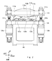
- FIG. 1 is a perspective view showing a configuration of the press device 100
- Fig. 2 is a front view showing the configuration of the press device 100.
- the press device 100 includes a first metal mold 110, a second metal mold 120, drive means 130a to 130d, and a base 140.
- the press device 100 sandwiches a work between the first and second metal molds 110 and 120, and thereby processes the work.
- the base 140 is fixed to the ground and supports the first and second metal molds 110 and 120, and the drive means 130a to 130d.
- the second metal mold 120 is fixed on the base 140, which is fixed to the ground.
- the first and second metal molds 110 and 120 are metal molds for sandwiching a work therebetween and thereby processing the work.
- the first metal mold 110 functions as an upper mold and the second metal mold 120 functions as a lower mold.
- the first metal mold 110 includes connection parts 111a to 111d for connecting with the drive means 130a to 130d.
- the second metal mold 120 includes connection parts 121a to 121d for connecting with the drive means 130a to 130d.
- One ends of the drive means 130a to 130d are connected to the connection parts 111a to 111d, respectively, of the first metal mold 110.
- the other ends of the drive means 130a to 130d are connected to the connection parts 121a to 121d, respectively, of the second metal mold 120.
- the drive means 130a to 130d can be easily removed from the connection parts 111a to 111d and the connection parts 121a to 121 d.
- Fig. 3 is a cross section of the first metal mold 110.
- Fig. 4 is a rear view of the first metal mold 110 removed from the press device 100.
- processing parts 112a to 112c are provided in the first metal mold 110.
- processing parts 122a to 122c are provided in the second metal mold 120.
- the processing parts 112a to 112c and the processing parts 122a to 122c are made of a metal having a strength higher than that of the work.
- the work can be processed by applying a pressure onto the molds in a state where the work is sandwiched between the processing parts 112a to 112c of the first metal mold 110 and the processing parts 122a to 122c of the second metal mold 120.
- the first metal mold 110 includes reinforcement parts 113a to 113d.
- a pressure is applied by connecting the drive means 130a to 130d at the comers of the first and second metal molds 110 and 120, a large bending stress is exerted on the first and second metal molds 110 and 120.
- warping occurs in the first and second metal molds 110 and 120 due to this bending stress.
- first and second metal molds 110 and 120 it is conceivable to ensure the rigidity of the first and second metal molds 110 and 120 by increasing the plate thicknesses of the first and second metal molds 110 and 120 in order to reduce the warping of the first and second metal molds 110 and 120.
- the plate thicknesses are increased, the weight of the metal molds increases, thus requiring large drive means 130a to 130d capable of producing large forces.
- the size and weight of the press device 100 increase. Therefore, it is conceivable to dispose a reinforcement part(s) on the peripheries of the first and second metal molds 110 and 120 in order to increase the strength of the metal molds without increasing their plate thicknesses.
- At least one of the first and second metal molds 110 and 120 preferably includes a reinforcement part.
- both of the first and second metal molds 110 and 120 may have reinforcement parts.
- the reinforcement part(s) may be provided on both of the front and rear surfaces or may be provided on only one of the front and rear surfaces.
- the reinforcement part is preferably disposed between neighboring connection parts.
- a reinforcement part 113a in Fig. 1 a hogback-shaped (or arc-shaped) rib having such a shape that an area near the connection part 111a is connected with an area near the connection part 111b by both ends of the arc can be used.
- the drive means 130a to 130d change the distance between the first and second metal molds 110 and 120. As shown in Fig. 5 , the drive means 130a to 130d are connected to the connection parts 111a to 111d, respectively of the first metal mold 110 and the connection parts 121 a to 121 d, respectively, of the second metal mold 120. Hydraulic means may be used for the drive means 130a to 130d. Alternatively, the drive means may be formed by combining servo-motors and ball screws. In the press device 100, the drive means 130a to 130d are formed by combining servo-motors and ball screws.
- the press device 100 can reduce the necessary maximum pressuring force compared to that in the crank press method.
- rotational energy accumulated in a flywheel is consumed little by little in each process. Therefore, the energy necessary for processing in each process needs to be calculated in a serial manner, thus requiring a large maximum pressuring force as a whole in the press device.
- the energy necessary for processing can be supplied in a continuous manner. Therefore, the pressuring force does not decrease during the process. Consequently, the energy necessary for each process can be calculated in a parallel manner, thus making it possible to reduce the necessary maximum pressuring force by shifting the processing timing in each process from one process to another process.
- the press device 100 does not use the plates, and the first and second metal molds 110 and 120, to which the drive means 130a to 130d are attached, are not deformed due to the driving forces generated by the drive means 130a to 130d.
- the plurality of drive means 130a to 130d can be individually controlled. This feature enables the first metal mold 110 to be moved freely.
- the pressuring force applied to the first metal mold 110 can be changed on a place-by-place basis by changing the force applied by each of the drive means 130a to 130d.
- the angle at which the first metal mold 110 comes into contact with the work can be changed by changing the driving speed of each of the drive means 130a to 130d so that one end of the first metal mold 110 is swiftly lowered while the other end of the first metal mold 110 is slowly lowered.
- Fig. 6 is a graph showing a movement of the first metal mold 110 when the connection parts 111a to 111d of the first metal mold 110 are moved in a disorderly manner.
- the horizontal axis in Fig. 6 indicates the time and the vertical axis indicates where the connection parts 111a to 111d of the first metal mold 110 are located between the upper dead point and the lower dead point.
- the first and second metal molds 110 and 120 may include a plurality of processing parts 112 and 122, to which a work is sent, according to the number of processing steps for the work.
- a forming process including a plurality of steps can be carried out by using a pair of metal molds (the first and second metal molds 110 and 120).
- FIG. 9 An arrangement of processing parts 122a to 122c in the rectangular second metal mold 120 having a length A in the work sending direction (left/right direction) is explained with reference to Figs. 9 and 10 .
- a plurality of the processing parts 122a to 122c are arranged at equal pitches such as intervals P1 in the work sending direction (left/right direction).
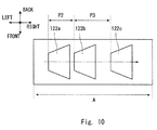
- the distance between the processing parts 122a and 122b in the work sending direction (left/right direction) is P2 and the distance between the processing parts 122b and 122c is P3. That is, the plurality of processing parts 122a to 122c are arranged at unequal pitches.
- a conveyance device using a link mechanism For the conveyance of a work in a crank-press type press device 100 using progressive metal molds, a conveyance device using a link mechanism is often used.
- the conveyance device using a link mechanism can convey works only in a straight line and its conveyance pitches are regular intervals.
- a revolute robot for conveying a work it is possible to automatically position the work in the processing parts 122a to 122c even for a metal mold in which the processing parts 122a to 122c are arranged at uneven pitches.
- the arrangement of the plurality of processing parts 122a to 122c at uneven pitches enables more flexible metal mold designs. Further, since the restriction for even pitches is eliminated, the distances between the processing parts can be reduced.
- a plurality of processing parts 122a to 122c are arranged in a staggered manner as viewed in the work sandwiching direction (up/down direction).
- a work is sent to the processing part 122a, to the processing part 122b, and to the processing part 122c in this order.
- the length of the second metal mold 120 in the work sending direction (left/right direction) is B and the length in (the front/back direction) is C, though the sizes of the processing parts 122a to 122c are the same as those in Figs. 9 and 10 .
- the second metal mold 120 is shortened in the left/right direction compared to the case where the processing parts 122a to 122c are arranged in a row, thus making it possible to reduce the size of the metal mold as a whole. Consequently, it is possible to improve the rigidity of the metal mold against bending.
- a revolute robot for conveying a work, it is possible to automatically position the work in the processing parts 122a to 122c even for a metal mold in which the processing parts 122a to 122c are disposed in a staggered manner.
- processing parts are arranged in two rows, there are cases where an operator cannot reach the row on the far side (the processing parts 122a and 122c) with his/her hand, thus making the conveyance of the work difficult.
- the use of a revolute robot makes it possible to cope with such an arrangement where an operator cannot reach a work with his/her hand.
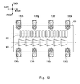
- a plurality of processing parts 122a to 122d are arranged in a point symmetry as viewed in the work sandwiching direction (up/down direction).
- a work is sent to the processing part 122a, to the processing part 122b, to the processing part 122c, and to the processing part 122d in this order.
- the second metal mold 120 is shortened in the left/right direction compared to the case where the processing parts 122a to 122d are arranged in a row, thus making it possible to reduce the size of the metal mold as a whole. Consequently, it is possible to improve the rigidity of the metal mold against bending.
- the first and second metal molds 110 and 120 include two sets of processing parts 301 and 302 in order to press a plurality of works for which the numbers of processing steps are different from each other.
- the number of sets of processing parts is not limited to two. That is, it may be any number equal to two or greater. For example, the number of sets may be three or greater.
- By providing a plurality of sets of processing parts a plurality of components can be processed by using one press device. As a result, the number of press devices in a factory can be reduced and hence the cost can be reduced.
- the pressuring force necessary for the presswork increases as the number of processing parts increases, the necessary pressuring force can be achieved by increasing the number of drive means.
- Fig. 14 shows an example of an arrangement in a case where the drive means have a two-axis configuration. The two axes are the minimum necessary number of the driving means in order to perform presswork while changing the pressuring force on the left side of the mold from that on the right side thereof and/or changing the pressing speed on the left side of the mold from that on the right side thereof.
- the drive means 130a and 130b are arranged near the centers of the short sides of the first metal mold 110 and are opposed to each other in the left/right direction.
- Fig. 15 shows an example of an arrangement in a case where the drive means have a three-axis configuration.
- a uniform pressuring force can be generated by arranging drive means 130a to 130c at regular intervals of 120 degrees in a peripheral section of the circular first metal mold 110.
- Fig. 16 shows an example of an arrangement in a case where the drive means have a four-axis configuration.
- a uniform pressuring force can be generated by arranging drive means 130a to 130c at the four corners of the first metal mold 110.
- Fig. 17 shows an example of an arrangement in a case where the drive means have a six-axis configuration or greater.
- 2n drive means 130F 1 -130F n and 130R 1 -130R n are arranged at regular intervals on the long sides of the first metal mold 110. This configuration makes it possible to generate a large pressuring force and generate a uniform pressuring force on the metal mold.
- a method for manufacturing a press device 100 is explained with reference to Fig. 18 .
- the shapes of the processing parts of the first and second metal molds 110 and 120 are determined in accordance with the shape of a component to be processed (ST401). In addition to the shapes of the processing parts, the arrangement of the processing parts in the mold is also determined.
- the positions of the connection parts in the first and second metal molds 110 and 120 are determined (ST402).
- the pressuring force necessary for the presswork can be calculated based on the shapes of the processing parts and the arrangement thereof in the mold.
- the number and arrangement of the drive means are determined so that the necessary pressuring force is obtained. Further, the positions of the connection parts are determined according to the determined number and arrangement of the drive means.
- the number of the drive means is four and four connection parts are arranged in each of the first and second metal molds 110 and 120.
- the first and second metal molds 110 and 120 are manufactured (ST403).
- the first and second metal molds 110 and 120 are manufactured by, for example, machining using a carbide tool.
- the first and second metal molds 110 and 120 are connected to each other through the plurality of drive means 130a to 130d (ST404).
- the drive means 130a to 130d are connected to the connection parts 111a to 111d, respectively, of the first metal mold 110 and the connection parts 121a to 121 d, respectively, of the second metal mold 120.
- the second metal mold 120 is fixed on the base 140.
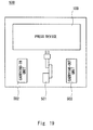
- the manufacturing line 500 includes the press device 100, a conveyance robot 501, a carrying-in unit 502, and a carrying-out unit 503.
- a work sent from the preceding process is carried into the carrying-in unit 502.
- the work, which has been processed by the press device 100 is carried out from the carrying-out unit 503 to the subsequent process.
- the conveyance robot 501 moves the work. That is, the conveyance robot 501 moves the work from the carrying-in unit 502 and positions it in the processing part of the press device 100, moves the work from one process site to another in the press device 100, and moves the work, which has been processed by the press device 100, to the carrying-out unit 503.
- a revolute robot is used as the conveyance robot 501.
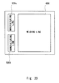
- a number of manufacturing lines 500 can be installed in a factory.
- a manufacturing line 500s for components S and a manufacturing line 500t for components T can be installed adjacent to a welding line 600.
- the line that is installed adjacent to the manufacturing lines 500s and 500t is not limited to the welding line 600. That is, an assembling line and/or a processing line may be installed adjacent to the manufacturing lines 500s and 500t.
- a press device 700 according to a second exemplary embodiment is explained with reference to Fig. 21 .
- the press device 700 includes a first metal mold 710, a second metal mold 720, a third metal mold 730, drive means 130a to 130d, a base 140, and poles 740a and 740b.
- the press device 700 sandwiches works between the first and second metal molds 710 and 720 and between the first and third metal molds 710 and 730, and thereby processes the works.
- the second metal mold 720 is fixed on the base 140 and the poles 740a and 740b are disposed in arranged positions in the second metal mold 720.
- Two through holes are formed in the first metal mold 710, and the first metal mold 710 is disposed so that it can be moved along the poles 740a and 740b through these through holes.
- the third metal mold 730 is fixed at the tops of the poles 740a and 740b.
- the first metal mold 710 can be vertically moved by the drive means 130a to 130d.
- the third metal mold 730 is disposed so that the first metal mold 710 is positioned between the second and third metal molds 720 and 730. That is, the third metal mold 730 is disposed above the first metal mold 710 in Fig. 21 .
- the first metal mold 710 includes connection parts 711a to 711d, lower processing parts 712a to 712c, and upper processing parts 714a and 714b.
- the second metal mold 720 includes connection parts 721a to 721d and processing parts 722a to 722c.
- the third metal mold 730 includes processing parts 732a and 732b and reinforcement parts 733a and 733b.
- FIG. 22 An operation of the press device 700 is explained with reference to Figs. 22 and 23 .
- Fig. 22 when the first metal mold 710 moves to the second metal mold 720 side, a work is processed by sandwiching the work between the upper processing parts 722a to 722c of the second metal mold 720 and the lower processing parts 712a to 712c of the first metal mold 710.
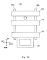
- the space between the first and third metal molds 710 and 730 is widened, a work can be easily placed on the processing parts 714a and 714b of the first metal mold 710 or a work that has been already placed there can be easily moved.
- the first metal mold 710 functions as an upper mold
- the second metal mold 720 functions as a lower mold in the press device 700.
- the first metal mold 710 moves to the third metal mold 730 side, a work is processed by sandwiching the work between the lower processing parts 732a and 732b of the third metal mold 730 and the upper processing parts 714a and 714b of the first metal mold 710.
- the space between the first and second metal molds 710 and 720 is widened, a work can be easily placed on the processing parts 722a to 722c of the second metal mold 720 or a work that has been already placed there can be easily moved.
- the first metal mold 710 functions as a lower mold and the third metal mold 730 functions as an upper mold in the press device 700.
- one presswork is performed by one reciprocating vertical motion of a metal mold.
- presswork can be performed twice by one reciprocating vertical motion of the first metal mold 710.
- the present invention is not limited to the above-described first exemplary embodiment, and it can be modified as appropriate without departing from the sprit and scope of the present invention.
- the press device according to the present invention is not limited to those in which the number of sets of metal molds is one or two. That is, the press device according to the present invention can also be applied to those where the number of sets of metal molds is three or more.
Landscapes
- Engineering & Computer Science (AREA)
- Mechanical Engineering (AREA)
- Press Drives And Press Lines (AREA)
- Control Of Presses (AREA)
- Mounting, Exchange, And Manufacturing Of Dies (AREA)
- Bending Of Plates, Rods, And Pipes (AREA)
Abstract
Description
- The present invention relates to a press device, a manufacturing line, and a manufacturing method of a press device.
- Various press devices are used for forming metal components. For example,
Patent Literature 1 discloses a press device capable of reducing the maximum load exerted on a work when a press forming is performed. In the press device disclosed inPatent Literature 1, a plurality of drive units support an upper mold plate and a lower mold plate. The upper mold of the metal mold is fixed on the bottom side of the upper mold plate and the lower mold of the metal mold is fixed on the top side of the lower mold plate. The plurality of drive units can be independently controlled. Therefore, by lowering the upper mold plate while swinging it, the maximum load in the forming process can be reduced. - Patent literature 1:
Japanese Unexamined Patent Application Publication No. 2012-125834 - In the press device disclosed in
Patent Literature 1, when a plurality of types of works are formed, it is necessary to adjust the size of the plates according to the size of the largest work. Therefore, the flexibility of design is low and the plates are unnecessarily large for the other works. As a result, the overall size of the press device including the plates increases. - The present invention has been made to solve the above-described problem and an object thereof is to provide a press device that is not unnecessarily large for works and hence has high design flexibility, a manufacturing line, and a manufacturing method of such a press device.
- A press device according to the present invention includes:
- a first metal mold;
- a second metal mold, the first and second metal molds being configured to sandwich a work therebetween and thereby process the work; and
- a plurality of drive means disposed to connect the first metal mold with the second metal mold, the plurality of drive means being configured to change a distance between the first and second metal molds, in which
- each of the first and second metal molds includes a connection part for connecting with the drive means, and at least one of the first and second metal molds includes a reinforcement part.
- In the present invention,
the first and second metal molds preferably include a plurality of processing parts, to which the work is sent, according to the number of processing steps for the work, and the plurality of processing parts are preferably arranged at unequal pitches in a work sending direction. - In the present invention,
the first and second metal molds preferably include a plurality of processing parts, to which the work is sent, according to the number of processing steps for the work, and the plurality of processing parts are preferably arranged in a staggered manner as viewed from a work sandwiching direction. - In the present invention,
the first and second metal molds preferably include a plurality of processing parts, to which the work is sent, according to the number of processing steps for the work, and the plurality of processing parts are preferably arranged in a point symmetry as viewed from a work sandwiching direction. - In the present invention,
the first and second metal molds preferably include a plurality of sets of processing parts in order to press a plurality of works for which the numbers of processing steps are different from each other. - In the present invention,
the press device preferably further includes a third metal mold disposed so that the first metal mold is positioned between the second and third metal molds,
when the first metal mold moves to the third metal mold side, the work is preferably processed by sandwiching the work between the third and first metal molds, and
when the first metal molds moves to the second metal mold side, the work is preferably processed by sandwiching the work between the second and first metal molds. - In the present invention,
the plurality of control means are preferably individually controlled. - A manufacturing line according to the present invention includes:
- the above-described press device; and
- a conveyance robot that conveys the work.
- A manufacturing method of a press device according to the present invention is
a manufacturing method of a press device,
the press device including: - a first metal mold;
- a second metal mold, the first and second metal molds being configured to sandwich a work therebetween and thereby process the work; and
- a plurality of drive means disposed to connect the first metal mold with the second metal mold, the plurality of drive means being configured to change a distance between the first and second metal molds,
- in which each of the first and second metal molds includes a connection part for connecting with the drive means, and
- in which the manufacturing method includes:
- a step of determining shapes of processing parts of the first and second metal molds in accordance with a shape of a component to be processed;
- a step of determining positions of the connection parts in the first and second metal molds;
- a step of manufacturing the first and second metal molds; and
- a step of connecting the first and second metal molds by the plurality of drive means.
- According to the present invention, it is possible to provide a press device that is not unnecessarily large for works and hence has high design flexibility, a manufacturing line, and a manufacturing method of such a press device.
-
-
Fig. 1 is a perspective view showing a configuration of a press device according to a first exemplary embodiment; -
Fig. 2 is a front view showing the configuration of the press device according to the first exemplary embodiment; -
Fig. 3 is a cross section of a first metal mold of the press device according to the first exemplary embodiment; -
Fig. 4 is a perspective view showing a configuration of the first metal mold removed from the press device according to the first exemplary embodiment; -
Fig. 5 shows a state where drive means is connected to the press device according to the first exemplary embodiment; -
Fig. 6 is a graph showing a movement of the first metal mold in the press device according to the first exemplary embodiment when connection parts of the first metal mold are moved in a disorderly manner; -
Fig. 7 is a schematic diagram showing a movement of the first metal mold in the press device according to the first exemplary embodiment when the connection parts of the first metal mold are moved in the disorderly manner; -
Fig. 8 is a graph showing how to move the first metal mold to prevent cracks in a work in the press device according to the first exemplary embodiment; -
Fig. 9 is a schematic diagram showing a second metal mold in which a plurality of processing parts are arranged at equal pitches in the press device according to the first exemplary embodiment; -
Fig. 10 is a schematic diagram showing a second metal mold in which a plurality of processing parts are arranged at unequal pitches in the press device according to the first exemplary embodiment; -
Fig. 11 is a schematic diagram showing a second metal mold in which a plurality of processing parts are arranged in a staggered manner in the press device according to the first exemplary embodiment; -
Fig. 12 is a schematic diagram showing a second metal mold in which a plurality of processing parts are arranged in a point symmetry in the press device according to the first exemplary embodiment; -
Fig. 13 is a schematic diagram showing a second metal mold including two sets of processing parts in the press device according to the first exemplary embodiment; -
Fig. 14 is a schematic diagram showing an example of an arrangement in the press device according to the first exemplary embodiment in a case where drive means have a two-axis configuration; -
Fig. 15 is a schematic diagram showing an example of an arrangement in the press device according to the first exemplary embodiment in a case where drive means have a three-axis configuration; -
Fig. 16 is a schematic diagram showing an example of an arrangement in the press device according to the first exemplary embodiment in a case where drive means have a four-axis configuration; -
Fig. 17 is a schematic diagram showing an example of an arrangement in the press device according to the first exemplary embodiment in a case where drive means have a six-axis configuration or greater; -
Fig. 18 is a flowchart showing a manufacturing method of a press device according to the first exemplary embodiment; -
Fig. 19 is a schematic diagram showing a configuration of a manufacturing line using a press device according to the first exemplary embodiment; -
Fig. 20 is a schematic diagram showing a manufacturing line in which a manufacturing line using a press device according to the first exemplary embodiment is combined with a welding line; -
Fig. 21 is a perspective view showing a configuration of a press device according to a second exemplary embodiment; -
Fig. 22 is a first diagram showing a motion of the press device according to the second exemplary embodiment; and -
Fig. 23 is a second diagram showing a motion of the press device according to the second exemplary embodiment. - Exemplary embodiments according to the present invention are explained hereinafter with reference to the drawings.
- A
press device 100 according to a first exemplary embodiment of the present invention is explained with reference toFigs. 1 to 5 .Fig. 1 is a perspective view showing a configuration of thepress device 100 andFig. 2 is a front view showing the configuration of thepress device 100. Thepress device 100 includes afirst metal mold 110, asecond metal mold 120, drive means 130a to 130d, and abase 140. Thepress device 100 sandwiches a work between the first andsecond metal molds - The
base 140 is fixed to the ground and supports the first andsecond metal molds second metal mold 120 is fixed on thebase 140, which is fixed to the ground. - The first and
second metal molds press device 100, thefirst metal mold 110 functions as an upper mold and thesecond metal mold 120 functions as a lower mold. Thefirst metal mold 110 includesconnection parts 111a to 111d for connecting with the drive means 130a to 130d. Thesecond metal mold 120 includesconnection parts 121a to 121d for connecting with the drive means 130a to 130d. One ends of the drive means 130a to 130d are connected to theconnection parts 111a to 111d, respectively, of thefirst metal mold 110. The other ends of the drive means 130a to 130d are connected to theconnection parts 121a to 121d, respectively, of thesecond metal mold 120. The drive means 130a to 130d can be easily removed from theconnection parts 111a to 111d and theconnection parts 121a to 121 d. -
Fig. 3 is a cross section of thefirst metal mold 110.Fig. 4 is a rear view of thefirst metal mold 110 removed from thepress device 100. As shown inFigs. 3 and4 ,processing parts 112a to 112c are provided in thefirst metal mold 110. Further, processingparts 122a to 122c are provided in thesecond metal mold 120. Theprocessing parts 112a to 112c and theprocessing parts 122a to 122c are made of a metal having a strength higher than that of the work. The work can be processed by applying a pressure onto the molds in a state where the work is sandwiched between theprocessing parts 112a to 112c of thefirst metal mold 110 and theprocessing parts 122a to 122c of thesecond metal mold 120. - The
first metal mold 110 includesreinforcement parts 113a to 113d. In thepress device 100, since a pressure is applied by connecting the drive means 130a to 130d at the comers of the first andsecond metal molds second metal molds second metal molds - It is conceivable to ensure the rigidity of the first and
second metal molds second metal molds second metal molds press device 100 increase. Therefore, it is conceivable to dispose a reinforcement part(s) on the peripheries of the first andsecond metal molds - Therefore, at least one of the first and
second metal molds second metal molds second metal molds reinforcement part 113a inFig. 1 , a hogback-shaped (or arc-shaped) rib having such a shape that an area near theconnection part 111a is connected with an area near theconnection part 111b by both ends of the arc can be used. - The drive means 130a to 130d change the distance between the first and
second metal molds Fig. 5 , the drive means 130a to 130d are connected to theconnection parts 111a to 111d, respectively of thefirst metal mold 110 and theconnection parts 121 a to 121 d, respectively, of thesecond metal mold 120. Hydraulic means may be used for the drive means 130a to 130d. Alternatively, the drive means may be formed by combining servo-motors and ball screws. In thepress device 100, the drive means 130a to 130d are formed by combining servo-motors and ball screws. - By using the plurality of drive means 130a to 130d, the
press device 100 can reduce the necessary maximum pressuring force compared to that in the crank press method. In a press device using the crank press method, rotational energy accumulated in a flywheel is consumed little by little in each process. Therefore, the energy necessary for processing in each process needs to be calculated in a serial manner, thus requiring a large maximum pressuring force as a whole in the press device. In contrast to this, in a press device using a servo press method or a hydraulic press method, the energy necessary for processing can be supplied in a continuous manner. Therefore, the pressuring force does not decrease during the process. Consequently, the energy necessary for each process can be calculated in a parallel manner, thus making it possible to reduce the necessary maximum pressuring force by shifting the processing timing in each process from one process to another process. - The
press device 100 does not use the plates, and the first andsecond metal molds - In the
press device 100, the plurality of drive means 130a to 130d can be individually controlled. This feature enables thefirst metal mold 110 to be moved freely. The pressuring force applied to thefirst metal mold 110 can be changed on a place-by-place basis by changing the force applied by each of the drive means 130a to 130d. Further, the angle at which thefirst metal mold 110 comes into contact with the work can be changed by changing the driving speed of each of the drive means 130a to 130d so that one end of thefirst metal mold 110 is swiftly lowered while the other end of thefirst metal mold 110 is slowly lowered. -
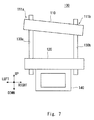
Fig. 6 is a graph showing a movement of thefirst metal mold 110 when theconnection parts 111a to 111d of thefirst metal mold 110 are moved in a disorderly manner. The horizontal axis inFig. 6 indicates the time and the vertical axis indicates where theconnection parts 111a to 111d of thefirst metal mold 110 are located between the upper dead point and the lower dead point. When thefirst metal mold 110 is moved as shown inFig. 6 , thefirst metal mold 110 is inclined so that theconnection part 111b side is lowered more than theconnection part 111a is as shown inFig. 7 . - Further, as shown in
Fig. 8 , when thefirst metal mold 110 is being moved from the upper dead point to the lower dead point, it is possible to temporarily stop thefirst meat mold 110 halfway between these points and then return thefirst metal mold 110 toward the upper dead point and then move thefirst metal mold 110 toward the lower dead point again. In this way, it is possible to reduce the bending stress exerted on the work during the forming process and thereby prevent or suppress cracks in the work. Further, it is possible to improve the accuracy of drawing press forming. Note that the horizontal axis inFig. 8 indicates the time and the vertical axis indicates where theconnection parts 111a to 111d of thefirst metal mold 110 are located between the upper dead point and the lower dead point. InFig. 8 , the drive means 130a to 130d perform the same movements. - Various arrangements of the processing parts 112 and 122 in the first and
second metal molds Figs. 9 to 13 . - The first and
second metal molds second metal molds 110 and 120). - An arrangement of
processing parts 122a to 122c in the rectangularsecond metal mold 120 having a length A in the work sending direction (left/right direction) is explained with reference toFigs. 9 and10 . InFig. 9 , a plurality of theprocessing parts 122a to 122c are arranged at equal pitches such as intervals P1 in the work sending direction (left/right direction). In contrast to this, inFig. 10 , the distance between theprocessing parts parts processing parts 122a to 122c are arranged at unequal pitches. - For the conveyance of a work in a crank-press
type press device 100 using progressive metal molds, a conveyance device using a link mechanism is often used. The conveyance device using a link mechanism can convey works only in a straight line and its conveyance pitches are regular intervals. However, by using a revolute robot for conveying a work, it is possible to automatically position the work in theprocessing parts 122a to 122c even for a metal mold in which theprocessing parts 122a to 122c are arranged at uneven pitches. The arrangement of the plurality ofprocessing parts 122a to 122c at uneven pitches enables more flexible metal mold designs. Further, since the restriction for even pitches is eliminated, the distances between the processing parts can be reduced. - In
Fig. 11 , a plurality ofprocessing parts 122a to 122c are arranged in a staggered manner as viewed in the work sandwiching direction (up/down direction). A work is sent to theprocessing part 122a, to theprocessing part 122b, and to theprocessing part 122c in this order. InFig. 11 , the length of thesecond metal mold 120 in the work sending direction (left/right direction) is B and the length in (the front/back direction) is C, though the sizes of theprocessing parts 122a to 122c are the same as those inFigs. 9 and10 . As a result, thesecond metal mold 120 is shortened in the left/right direction compared to the case where theprocessing parts 122a to 122c are arranged in a row, thus making it possible to reduce the size of the metal mold as a whole. Consequently, it is possible to improve the rigidity of the metal mold against bending. - By using a revolute robot for conveying a work, it is possible to automatically position the work in the
processing parts 122a to 122c even for a metal mold in which theprocessing parts 122a to 122c are disposed in a staggered manner. In the case where processing parts are arranged in two rows, there are cases where an operator cannot reach the row on the far side (theprocessing parts - In
Fig. 12 , a plurality ofprocessing parts 122a to 122d are arranged in a point symmetry as viewed in the work sandwiching direction (up/down direction). A work is sent to theprocessing part 122a, to theprocessing part 122b, to theprocessing part 122c, and to theprocessing part 122d in this order. Thesecond metal mold 120 is shortened in the left/right direction compared to the case where theprocessing parts 122a to 122d are arranged in a row, thus making it possible to reduce the size of the metal mold as a whole. Consequently, it is possible to improve the rigidity of the metal mold against bending. By using a revolute robot for conveying a work, it is possible to automatically position the work in theprocessing parts 122a to 122d even for a metal mold in which theprocessing parts 122a to 122d are disposed in a point symmetry. Further, although the length of thesecond metal mold 120 in the work sending direction (left/right direction) is B and the length in (the front/back direction) is C as in the case ofFig. 11 , the number of processing parts that can be arranged in thesecond metal mold 120 is larger than that in the case ofFig. 11 by one. - In
Fig. 13 , the first andsecond metal molds parts - An arrangement of drive means is explained with reference to
Figs. 14 to 17 . The number and arrangement of the drive means are determined based on the shapes of the first andsecond metal molds press device 100 can generate.Fig. 14 shows an example of an arrangement in a case where the drive means have a two-axis configuration. The two axes are the minimum necessary number of the driving means in order to perform presswork while changing the pressuring force on the left side of the mold from that on the right side thereof and/or changing the pressing speed on the left side of the mold from that on the right side thereof. The drive means 130a and 130b are arranged near the centers of the short sides of thefirst metal mold 110 and are opposed to each other in the left/right direction. -
Fig. 15 shows an example of an arrangement in a case where the drive means have a three-axis configuration. A uniform pressuring force can be generated by arranging drive means 130a to 130c at regular intervals of 120 degrees in a peripheral section of the circularfirst metal mold 110. -
Fig. 16 shows an example of an arrangement in a case where the drive means have a four-axis configuration. A uniform pressuring force can be generated by arranging drive means 130a to 130c at the four corners of thefirst metal mold 110. -
Fig. 17 shows an example of an arrangement in a case where the drive means have a six-axis configuration or greater. In total, 2n drive means 130F1-130Fn and 130R1-130Rn are arranged at regular intervals on the long sides of thefirst metal mold 110. This configuration makes it possible to generate a large pressuring force and generate a uniform pressuring force on the metal mold. - A method for manufacturing a
press device 100 is explained with reference toFig. 18 . - Firstly, the shapes of the processing parts of the first and
second metal molds - Next, the positions of the connection parts in the first and
second metal molds press device 100, the number of the drive means is four and four connection parts are arranged in each of the first andsecond metal molds - Next, the first and
second metal molds second metal molds - The first and
second metal molds connection parts 111a to 111d, respectively, of thefirst metal mold 110 and theconnection parts 121a to 121 d, respectively, of thesecond metal mold 120. At this time, thesecond metal mold 120 is fixed on thebase 140. - A
manufacturing line 500 using thepress device 100 is explained with reference toFig. 19 . Themanufacturing line 500 includes thepress device 100, aconveyance robot 501, a carrying-inunit 502, and a carrying-outunit 503. - A work sent from the preceding process is carried into the carrying-in
unit 502. The work, which has been processed by thepress device 100, is carried out from the carrying-outunit 503 to the subsequent process. Theconveyance robot 501 moves the work. That is, theconveyance robot 501 moves the work from the carrying-inunit 502 and positions it in the processing part of thepress device 100, moves the work from one process site to another in thepress device 100, and moves the work, which has been processed by thepress device 100, to the carrying-outunit 503. For example a revolute robot is used as theconveyance robot 501. By combining thepress device 100 with theconveyance robot 501, a small and low-cost manufacturing line 500 can be constructed. - Since the cost of the
manufacturing line 500 is low, a number ofmanufacturing lines 500 can be installed in a factory. For example, as shown inFig. 20 , amanufacturing line 500s for components S and amanufacturing line 500t for components T can be installed adjacent to awelding line 600. The line that is installed adjacent to themanufacturing lines welding line 600. That is, an assembling line and/or a processing line may be installed adjacent to themanufacturing lines - As a result, in comparison to related-art lot production, it is possible to supply only the necessary number of components to the subsequent process when they are required, thus eliminating the need for storing excess components and enabling the manufacturing cost to be lowered.
- As has been explained above, according to the present invention, it is possible to provide a press device that is not unnecessarily large for works and hence has high design flexibility, a manufacturing line, and a manufacturing method of such a press device.
- A
press device 700 according to a second exemplary embodiment is explained with reference toFig. 21 . Thepress device 700 includes afirst metal mold 710, asecond metal mold 720, athird metal mold 730, drive means 130a to 130d, abase 140, andpoles press device 700 sandwiches works between the first andsecond metal molds third metal molds - In the
press device 700, thesecond metal mold 720 is fixed on thebase 140 and thepoles second metal mold 720. Two through holes are formed in thefirst metal mold 710, and thefirst metal mold 710 is disposed so that it can be moved along thepoles third metal mold 730 is fixed at the tops of thepoles first metal mold 710 can be vertically moved by the drive means 130a to 130d. - The
third metal mold 730 is disposed so that thefirst metal mold 710 is positioned between the second andthird metal molds third metal mold 730 is disposed above thefirst metal mold 710 inFig. 21 . - The
first metal mold 710 includesconnection parts 711a to 711d,lower processing parts 712a to 712c, andupper processing parts second metal mold 720 includesconnection parts 721a to 721d and processing parts 722a to 722c. Thethird metal mold 730 includesprocessing parts reinforcement parts - An operation of the
press device 700 is explained with reference toFigs. 22 and23 . As shown inFig. 22 , when thefirst metal mold 710 moves to thesecond metal mold 720 side, a work is processed by sandwiching the work between the upper processing parts 722a to 722c of thesecond metal mold 720 and thelower processing parts 712a to 712c of thefirst metal mold 710. In this state, since the space between the first andthird metal molds processing parts first metal mold 710 or a work that has been already placed there can be easily moved. In this case, thefirst metal mold 710 functions as an upper mold and thesecond metal mold 720 functions as a lower mold in thepress device 700. - As shown in
Fig. 23 , when thefirst metal mold 710 moves to thethird metal mold 730 side, a work is processed by sandwiching the work between thelower processing parts third metal mold 730 and theupper processing parts first metal mold 710. In this state, since the space between the first andsecond metal molds second metal mold 720 or a work that has been already placed there can be easily moved. In this case, thefirst metal mold 710 functions as a lower mold and thethird metal mold 730 functions as an upper mold in thepress device 700. - In an ordinary press device, one presswork is performed by one reciprocating vertical motion of a metal mold. In contrast to this, in the
press device 700 according to this exemplary embodiment, presswork can be performed twice by one reciprocating vertical motion of thefirst metal mold 710. As a result, since the number of processes that can be carried out by one press device increases, the number of press devices used in the whole processes can be reduced. Consequently, the manufacturing cost can be reduced. Further, since the number of components that can be simultaneously processed by one press device increases, it can be expected that the manufacturing cost can be reduced owing to the improvement in the productivity. - Note that the present invention is not limited to the above-described first exemplary embodiment, and it can be modified as appropriate without departing from the sprit and scope of the present invention. For example, the press device according to the present invention is not limited to those in which the number of sets of metal molds is one or two. That is, the press device according to the present invention can also be applied to those where the number of sets of metal molds is three or more.
- This application is based upon and claims the benefit of priority from
Japanese patent application No. 2013-215540 -
- 100, 700 PRESS DEVICE
- 110,710 FIRST METAL MOLD
- 120, 720 SECOND METAL MOLD
- 111a-111d, 121a-121d, 711a-711d, 721a-721d CONNECTION PART
- 112a-112c, 122a-122c, 712a-712c, 722a-722c, 714a, 714b, 732a, 732b PROCESSING PART
- 113a-113d, 733a, 733b REINFORCEMENT PART
- 130a-130d DRIVE MEANS
- 140 BASE
- 500 MANUFACTURING LINE
- 600 WELDING LINE
- 730 THIRD METAL MOLD
- 740a, 740b POLE
Claims (9)
- A press device comprising:a first metal mold;a second metal mold, the first and second metal molds being configured to sandwich a work therebetween and thereby process the work; anda plurality of drive means disposed to connect the first metal mold with the second metal mold, the plurality of drive means being configured to change a distance between the first and second metal molds, whereineach of the first and second metal molds comprises a connection part for connecting with the drive means, and at least one of the first and second metal molds comprises a reinforcement part.
- The press device according to Claim 1, wherein the first and second metal molds comprise a plurality of processing parts, to which the work is sent, according to the number of processing steps for the work, and the plurality of processing parts are arranged at unequal pitches in a work sending direction.
- The press device according to Claim 1, wherein the first and second metal molds comprise a plurality of processing parts, to which the work is sent, according to the number of processing steps for the work, and the plurality of processing parts are arranged in a staggered manner as viewed from a work sandwiching direction.
- The press device according to Claim 1, wherein the first and second metal molds comprise a plurality of processing parts, to which the work is sent, according to the number of processing steps for the work, and the plurality of processing parts are arranged in a point symmetry as viewed from a work sandwiching direction.
- The press device according to Claim 1, wherein the first and second metal molds comprise a plurality of sets of processing parts in order to press a plurality of works for which the numbers of processing steps are different from each other.
- The press device according to any one of Claims 1 to 5, further comprising a third metal mold disposed so that the first metal mold is positioned between the second and third metal molds, wherein
when the first metal mold moves to the third metal mold side, the work is processed by sandwiching the work between the third and first metal molds, and
when the first metal molds moves to the second metal mold side, the work is processed by sandwiching the work between the second and first metal molds. - The press device according to any one of Claims 1 to 6, wherein the plurality of control means are individually controlled.
- A manufacturing line comprising:a press device according to any one of Claims 1 to 7; anda conveyance robot that conveys the work.
- A manufacturing method of a press device,
the press device comprising:a first metal mold;a second metal mold, the first and second metal molds being configured to sandwich a work therebetween and thereby process the work; anda plurality of drive means disposed to connect the first metal mold with the second metal mold, the plurality of drive means being configured to change a distance between the first and second metal molds,wherein each of the first and second metal molds comprises a connection part for connecting with the drive means, andwherein the manufacturing method comprises:a step of determining shapes of processing parts of the first and second metal molds in accordance with a shape of a component to be processed;a step of determining positions of the connection parts in the first and second metal molds;a step of manufacturing the first and second metal molds; anda step of connecting the first and second metal molds by the plurality of drive means.
Applications Claiming Priority (2)
| Application Number | Priority Date | Filing Date | Title |
|---|---|---|---|
| JP2013215540A JP5967049B2 (en) | 2013-10-16 | 2013-10-16 | Press equipment, production line |
| PCT/JP2014/004652 WO2015056398A1 (en) | 2013-10-16 | 2014-09-10 | Press device, production line, and press device production method |
Publications (3)
| Publication Number | Publication Date |
|---|---|
| EP3059079A1 true EP3059079A1 (en) | 2016-08-24 |
| EP3059079A4 EP3059079A4 (en) | 2016-12-28 |
| EP3059079B1 EP3059079B1 (en) | 2022-09-21 |
Family
ID=52827860
Family Applications (1)
| Application Number | Title | Priority Date | Filing Date |
|---|---|---|---|
| EP14854379.6A Active EP3059079B1 (en) | 2013-10-16 | 2014-09-10 | Press device and press device production method |
Country Status (6)
| Country | Link |
|---|---|
| US (1) | US10369610B2 (en) |
| EP (1) | EP3059079B1 (en) |
| JP (1) | JP5967049B2 (en) |
| CN (1) | CN105612049B (en) |
| BR (1) | BR112016008099B1 (en) |
| WO (1) | WO2015056398A1 (en) |
Families Citing this family (7)
| Publication number | Priority date | Publication date | Assignee | Title |
|---|---|---|---|---|
| CN106391964B (en) * | 2016-10-17 | 2018-01-23 | 燕山大学 | A kind of freedom degree parallel connection forging press |
| JP7063074B2 (en) * | 2018-04-11 | 2022-05-09 | トヨタ紡織株式会社 | Press processing equipment |
| CN109049823B (en) * | 2018-08-01 | 2020-07-24 | 江铃汽车股份有限公司 | Anti-unbalance-loading device and press equipment comprising same |
| JP7132879B2 (en) * | 2019-03-28 | 2022-09-07 | 株式会社アマダ | Mold press device and mold press method |
| WO2025018593A1 (en) * | 2023-07-19 | 2025-01-23 | 삼성전자 주식회사 | Compression device |
| CN116673400B (en) * | 2023-08-03 | 2023-09-26 | 龙口通力汽车零部件制造有限公司 | Fender mould |
| CN117862308B (en) * | 2024-01-29 | 2024-08-06 | 昆山陆新新材料科技有限公司 | Rapid die pressing forming equipment and method for processing aluminum alloy metal plate |
Family Cites Families (14)
| Publication number | Priority date | Publication date | Assignee | Title |
|---|---|---|---|---|
| JPH04253598A (en) * | 1991-01-31 | 1992-09-09 | Toyota Motor Corp | Multi-stage pressurizing device |
| JPH08174295A (en) * | 1994-12-27 | 1996-07-09 | Komatsu Ltd | Press machine |
| JP2001001186A (en) * | 1999-06-23 | 2001-01-09 | Yamada Dobby Co Ltd | Double action slide press |
| JP2001079735A (en) * | 1999-09-13 | 2001-03-27 | Orii & Mec Corp | Multi-section processing equipment for strip materials |
| JP3682011B2 (en) * | 2001-10-23 | 2005-08-10 | 株式会社放電精密加工研究所 | Press machine |
| JP2003145299A (en) * | 2001-11-08 | 2003-05-20 | Toyota Motor Corp | Method of using press machine and press machine |
| JP4852087B2 (en) * | 2004-02-12 | 2012-01-11 | 株式会社キマタ | Press mold equipment |
| KR100899624B1 (en) * | 2004-07-29 | 2009-05-27 | 도요타 지도샤(주) | Press molder |
| CN102458709B (en) * | 2009-06-09 | 2014-07-30 | 夏伊洛工业公司 | Apparatus, system and method for manufacturing metal parts |
| JP5714823B2 (en) * | 2010-02-01 | 2015-05-07 | 小島プレス工業株式会社 | Molding equipment |
| CN103328198B (en) | 2010-11-30 | 2015-12-16 | 小岛冲压工业株式会社 | Stamping machine |
| JP5760422B2 (en) * | 2010-12-15 | 2015-08-12 | トヨタ自動車株式会社 | Press apparatus and press method |
| JP5764920B2 (en) | 2010-12-17 | 2015-08-19 | トヨタ自動車株式会社 | Press machine |
| JP5953682B2 (en) * | 2011-09-12 | 2016-07-20 | 日立金属株式会社 | Forging equipment |
-
2013
- 2013-10-16 JP JP2013215540A patent/JP5967049B2/en not_active Expired - Fee Related
-
2014
- 2014-09-10 CN CN201480050225.6A patent/CN105612049B/en not_active Expired - Fee Related
- 2014-09-10 EP EP14854379.6A patent/EP3059079B1/en active Active
- 2014-09-10 WO PCT/JP2014/004652 patent/WO2015056398A1/en not_active Ceased
- 2014-09-10 BR BR112016008099-8A patent/BR112016008099B1/en not_active IP Right Cessation
- 2014-09-10 US US14/916,711 patent/US10369610B2/en not_active Expired - Fee Related
Also Published As
| Publication number | Publication date |
|---|---|
| WO2015056398A1 (en) | 2015-04-23 |
| BR112016008099B1 (en) | 2022-04-19 |
| EP3059079B1 (en) | 2022-09-21 |
| CN105612049A (en) | 2016-05-25 |
| BR112016008099A2 (en) | 2017-08-01 |
| JP2015077609A (en) | 2015-04-23 |
| US10369610B2 (en) | 2019-08-06 |
| JP5967049B2 (en) | 2016-08-10 |
| EP3059079A4 (en) | 2016-12-28 |
| US20160214160A1 (en) | 2016-07-28 |
| CN105612049B (en) | 2017-04-26 |
Similar Documents
| Publication | Publication Date | Title |
|---|---|---|
| EP3059079B1 (en) | Press device and press device production method | |
| EP2571659B1 (en) | Robot cell apparatus and production system | |
| RU2534651C2 (en) | Machine with variable linear geometry for continuous forming of pipes with square cross-section | |
| CN106271075A (en) | Welding splicing mechanical hand and laser assembly solder system | |
| JP6588743B2 (en) | Roll forging machine and its roll forging method | |
| KR100838512B1 (en) | Jig Device for Rack Making | |
| WO2021060274A1 (en) | Method for manufacturing press-formed article, press-formed article, and press-forming device | |
| JP5656804B2 (en) | Assembly robot device | |
| JP2013000857A (en) | Robot hand | |
| JP6761485B2 (en) | Work machine | |
| KR101432092B1 (en) | roller type panel bending device | |
| JP2012125810A (en) | Press device and pressing method | |
| JP5434769B2 (en) | Gripping device and method | |
| JP3201031U (en) | Spring wire machine molding machine | |
| CN109807218A (en) | A kind of multistation spinning machine | |
| WO2018173657A1 (en) | Welding path specification method, program, teaching program and welding robot system | |
| JP6565469B2 (en) | Vibration control device and processing machine | |
| JP3237925U (en) | Table for processing machine | |
| JP5942976B2 (en) | Processing apparatus and bending method | |
| JP2011025354A (en) | Production system | |
| JP2021023963A (en) | Sheet metal flexural processing method | |
| KR101282059B1 (en) | Apparatus for screwing using asymmetry multi-gantry | |
| CN106011437B (en) | The carburizing and quenching frock of bent axle | |
| KR101417939B1 (en) | bending machine | |
| JP6011322B2 (en) | Press machine |
Legal Events
| Date | Code | Title | Description |
|---|---|---|---|
| PUAI | Public reference made under article 153(3) epc to a published international application that has entered the european phase |
Free format text: ORIGINAL CODE: 0009012 |
|
| 17P | Request for examination filed |
Effective date: 20160317 |
|
| AK | Designated contracting states |
Kind code of ref document: A1 Designated state(s): AL AT BE BG CH CY CZ DE DK EE ES FI FR GB GR HR HU IE IS IT LI LT LU LV MC MK MT NL NO PL PT RO RS SE SI SK SM TR |
|
| AX | Request for extension of the european patent |
Extension state: BA ME |
|
| A4 | Supplementary search report drawn up and despatched |
Effective date: 20161128 |
|
| RIC1 | Information provided on ipc code assigned before grant |
Ipc: B30B 15/00 20060101ALI20161122BHEP Ipc: B21D 22/02 20060101ALI20161122BHEP Ipc: B21D 37/20 20060101ALI20161122BHEP Ipc: B30B 15/02 20060101AFI20161122BHEP Ipc: B30B 1/18 20060101ALI20161122BHEP Ipc: B21D 37/12 20060101ALI20161122BHEP Ipc: B30B 15/14 20060101ALI20161122BHEP |
|
| DAX | Request for extension of the european patent (deleted) | ||
| STAA | Information on the status of an ep patent application or granted ep patent |
Free format text: STATUS: EXAMINATION IS IN PROGRESS |
|
| 17Q | First examination report despatched |
Effective date: 20170608 |
|
| GRAP | Despatch of communication of intention to grant a patent |
Free format text: ORIGINAL CODE: EPIDOSNIGR1 |
|
| STAA | Information on the status of an ep patent application or granted ep patent |
Free format text: STATUS: GRANT OF PATENT IS INTENDED |
|
| INTG | Intention to grant announced |
Effective date: 20220524 |
|
| GRAS | Grant fee paid |
Free format text: ORIGINAL CODE: EPIDOSNIGR3 |
|
| GRAA | (expected) grant |
Free format text: ORIGINAL CODE: 0009210 |
|
| STAA | Information on the status of an ep patent application or granted ep patent |
Free format text: STATUS: THE PATENT HAS BEEN GRANTED |
|
| AK | Designated contracting states |
Kind code of ref document: B1 Designated state(s): AL AT BE BG CH CY CZ DE DK EE ES FI FR GB GR HR HU IE IS IT LI LT LU LV MC MK MT NL NO PL PT RO RS SE SI SK SM TR |
|
| REG | Reference to a national code |
Ref country code: GB Ref legal event code: FG4D |
|
| REG | Reference to a national code |
Ref country code: CH Ref legal event code: EP |
|
| REG | Reference to a national code |
Ref country code: DE Ref legal event code: R096 Ref document number: 602014085024 Country of ref document: DE |
|
| REG | Reference to a national code |
Ref country code: IE Ref legal event code: FG4D |
|
| REG | Reference to a national code |
Ref country code: AT Ref legal event code: REF Ref document number: 1519764 Country of ref document: AT Kind code of ref document: T Effective date: 20221015 |
|
| REG | Reference to a national code |
Ref country code: LT Ref legal event code: MG9D |
|
| REG | Reference to a national code |
Ref country code: NL Ref legal event code: MP Effective date: 20220921 |
|
| PG25 | Lapsed in a contracting state [announced via postgrant information from national office to epo] |
Ref country code: SE Free format text: LAPSE BECAUSE OF FAILURE TO SUBMIT A TRANSLATION OF THE DESCRIPTION OR TO PAY THE FEE WITHIN THE PRESCRIBED TIME-LIMIT Effective date: 20220921 Ref country code: RS Free format text: LAPSE BECAUSE OF FAILURE TO SUBMIT A TRANSLATION OF THE DESCRIPTION OR TO PAY THE FEE WITHIN THE PRESCRIBED TIME-LIMIT Effective date: 20220921 Ref country code: NO Free format text: LAPSE BECAUSE OF FAILURE TO SUBMIT A TRANSLATION OF THE DESCRIPTION OR TO PAY THE FEE WITHIN THE PRESCRIBED TIME-LIMIT Effective date: 20221221 Ref country code: LV Free format text: LAPSE BECAUSE OF FAILURE TO SUBMIT A TRANSLATION OF THE DESCRIPTION OR TO PAY THE FEE WITHIN THE PRESCRIBED TIME-LIMIT Effective date: 20220921 Ref country code: LT Free format text: LAPSE BECAUSE OF FAILURE TO SUBMIT A TRANSLATION OF THE DESCRIPTION OR TO PAY THE FEE WITHIN THE PRESCRIBED TIME-LIMIT Effective date: 20220921 Ref country code: FI Free format text: LAPSE BECAUSE OF FAILURE TO SUBMIT A TRANSLATION OF THE DESCRIPTION OR TO PAY THE FEE WITHIN THE PRESCRIBED TIME-LIMIT Effective date: 20220921 |
|
| REG | Reference to a national code |
Ref country code: AT Ref legal event code: MK05 Ref document number: 1519764 Country of ref document: AT Kind code of ref document: T Effective date: 20220921 |
|
| PG25 | Lapsed in a contracting state [announced via postgrant information from national office to epo] |
Ref country code: HR Free format text: LAPSE BECAUSE OF FAILURE TO SUBMIT A TRANSLATION OF THE DESCRIPTION OR TO PAY THE FEE WITHIN THE PRESCRIBED TIME-LIMIT Effective date: 20220921 Ref country code: GR Free format text: LAPSE BECAUSE OF FAILURE TO SUBMIT A TRANSLATION OF THE DESCRIPTION OR TO PAY THE FEE WITHIN THE PRESCRIBED TIME-LIMIT Effective date: 20221222 |
|
| PG25 | Lapsed in a contracting state [announced via postgrant information from national office to epo] |
Ref country code: SM Free format text: LAPSE BECAUSE OF FAILURE TO SUBMIT A TRANSLATION OF THE DESCRIPTION OR TO PAY THE FEE WITHIN THE PRESCRIBED TIME-LIMIT Effective date: 20220921 Ref country code: RO Free format text: LAPSE BECAUSE OF FAILURE TO SUBMIT A TRANSLATION OF THE DESCRIPTION OR TO PAY THE FEE WITHIN THE PRESCRIBED TIME-LIMIT Effective date: 20220921 Ref country code: PT Free format text: LAPSE BECAUSE OF FAILURE TO SUBMIT A TRANSLATION OF THE DESCRIPTION OR TO PAY THE FEE WITHIN THE PRESCRIBED TIME-LIMIT Effective date: 20230123 Ref country code: ES Free format text: LAPSE BECAUSE OF FAILURE TO SUBMIT A TRANSLATION OF THE DESCRIPTION OR TO PAY THE FEE WITHIN THE PRESCRIBED TIME-LIMIT Effective date: 20220921 Ref country code: CZ Free format text: LAPSE BECAUSE OF FAILURE TO SUBMIT A TRANSLATION OF THE DESCRIPTION OR TO PAY THE FEE WITHIN THE PRESCRIBED TIME-LIMIT Effective date: 20220921 Ref country code: AT Free format text: LAPSE BECAUSE OF FAILURE TO SUBMIT A TRANSLATION OF THE DESCRIPTION OR TO PAY THE FEE WITHIN THE PRESCRIBED TIME-LIMIT Effective date: 20220921 |
|
| PG25 | Lapsed in a contracting state [announced via postgrant information from national office to epo] |
Ref country code: SK Free format text: LAPSE BECAUSE OF FAILURE TO SUBMIT A TRANSLATION OF THE DESCRIPTION OR TO PAY THE FEE WITHIN THE PRESCRIBED TIME-LIMIT Effective date: 20220921 Ref country code: PL Free format text: LAPSE BECAUSE OF FAILURE TO SUBMIT A TRANSLATION OF THE DESCRIPTION OR TO PAY THE FEE WITHIN THE PRESCRIBED TIME-LIMIT Effective date: 20220921 Ref country code: IS Free format text: LAPSE BECAUSE OF FAILURE TO SUBMIT A TRANSLATION OF THE DESCRIPTION OR TO PAY THE FEE WITHIN THE PRESCRIBED TIME-LIMIT Effective date: 20230121 Ref country code: EE Free format text: LAPSE BECAUSE OF FAILURE TO SUBMIT A TRANSLATION OF THE DESCRIPTION OR TO PAY THE FEE WITHIN THE PRESCRIBED TIME-LIMIT Effective date: 20220921 |
|
| P01 | Opt-out of the competence of the unified patent court (upc) registered |
Effective date: 20230427 |
|
| REG | Reference to a national code |
Ref country code: DE Ref legal event code: R097 Ref document number: 602014085024 Country of ref document: DE |
|
| REG | Reference to a national code |
Ref country code: DE Ref legal event code: R084 Ref document number: 602014085024 Country of ref document: DE |
|
| PG25 | Lapsed in a contracting state [announced via postgrant information from national office to epo] |
Ref country code: NL Free format text: LAPSE BECAUSE OF FAILURE TO SUBMIT A TRANSLATION OF THE DESCRIPTION OR TO PAY THE FEE WITHIN THE PRESCRIBED TIME-LIMIT Effective date: 20220921 Ref country code: AL Free format text: LAPSE BECAUSE OF FAILURE TO SUBMIT A TRANSLATION OF THE DESCRIPTION OR TO PAY THE FEE WITHIN THE PRESCRIBED TIME-LIMIT Effective date: 20220921 |
|
| PLBE | No opposition filed within time limit |
Free format text: ORIGINAL CODE: 0009261 |
|
| STAA | Information on the status of an ep patent application or granted ep patent |
Free format text: STATUS: NO OPPOSITION FILED WITHIN TIME LIMIT |
|
| PG25 | Lapsed in a contracting state [announced via postgrant information from national office to epo] |
Ref country code: DK Free format text: LAPSE BECAUSE OF FAILURE TO SUBMIT A TRANSLATION OF THE DESCRIPTION OR TO PAY THE FEE WITHIN THE PRESCRIBED TIME-LIMIT Effective date: 20220921 |
|
| 26N | No opposition filed |
Effective date: 20230622 |
|
| PG25 | Lapsed in a contracting state [announced via postgrant information from national office to epo] |
Ref country code: SI Free format text: LAPSE BECAUSE OF FAILURE TO SUBMIT A TRANSLATION OF THE DESCRIPTION OR TO PAY THE FEE WITHIN THE PRESCRIBED TIME-LIMIT Effective date: 20220921 |
|
| REG | Reference to a national code |
Ref country code: DE Ref legal event code: R119 Ref document number: 602014085024 Country of ref document: DE |
|
| REG | Reference to a national code |
Ref country code: CH Ref legal event code: PL |
|
| PG25 | Lapsed in a contracting state [announced via postgrant information from national office to epo] |
Ref country code: LU Free format text: LAPSE BECAUSE OF NON-PAYMENT OF DUE FEES Effective date: 20230910 |
|
| REG | Reference to a national code |
Ref country code: BE Ref legal event code: MM Effective date: 20230930 |
|
| GBPC | Gb: european patent ceased through non-payment of renewal fee |
Effective date: 20230910 |
|
| PG25 | Lapsed in a contracting state [announced via postgrant information from national office to epo] |
Ref country code: LU Free format text: LAPSE BECAUSE OF NON-PAYMENT OF DUE FEES Effective date: 20230910 Ref country code: IT Free format text: LAPSE BECAUSE OF FAILURE TO SUBMIT A TRANSLATION OF THE DESCRIPTION OR TO PAY THE FEE WITHIN THE PRESCRIBED TIME-LIMIT Effective date: 20220921 Ref country code: MC Free format text: LAPSE BECAUSE OF FAILURE TO SUBMIT A TRANSLATION OF THE DESCRIPTION OR TO PAY THE FEE WITHIN THE PRESCRIBED TIME-LIMIT Effective date: 20220921 |
|
| REG | Reference to a national code |
Ref country code: IE Ref legal event code: MM4A |
|
| PG25 | Lapsed in a contracting state [announced via postgrant information from national office to epo] |
Ref country code: IE Free format text: LAPSE BECAUSE OF NON-PAYMENT OF DUE FEES Effective date: 20230910 |
|
| PG25 | Lapsed in a contracting state [announced via postgrant information from national office to epo] |
Ref country code: GB Free format text: LAPSE BECAUSE OF NON-PAYMENT OF DUE FEES Effective date: 20230910 |
|
| PG25 | Lapsed in a contracting state [announced via postgrant information from national office to epo] |
Ref country code: CH Free format text: LAPSE BECAUSE OF NON-PAYMENT OF DUE FEES Effective date: 20230930 |
|
| PG25 | Lapsed in a contracting state [announced via postgrant information from national office to epo] |
Ref country code: IE Free format text: LAPSE BECAUSE OF NON-PAYMENT OF DUE FEES Effective date: 20230910 Ref country code: GB Free format text: LAPSE BECAUSE OF NON-PAYMENT OF DUE FEES Effective date: 20230910 Ref country code: FR Free format text: LAPSE BECAUSE OF NON-PAYMENT OF DUE FEES Effective date: 20230930 Ref country code: DE Free format text: LAPSE BECAUSE OF NON-PAYMENT OF DUE FEES Effective date: 20240403 Ref country code: CH Free format text: LAPSE BECAUSE OF NON-PAYMENT OF DUE FEES Effective date: 20230930 |
|
| PG25 | Lapsed in a contracting state [announced via postgrant information from national office to epo] |
Ref country code: BE Free format text: LAPSE BECAUSE OF NON-PAYMENT OF DUE FEES Effective date: 20230930 |
|
| PG25 | Lapsed in a contracting state [announced via postgrant information from national office to epo] |
Ref country code: BG Free format text: LAPSE BECAUSE OF FAILURE TO SUBMIT A TRANSLATION OF THE DESCRIPTION OR TO PAY THE FEE WITHIN THE PRESCRIBED TIME-LIMIT Effective date: 20220921 |
|
| PG25 | Lapsed in a contracting state [announced via postgrant information from national office to epo] |
Ref country code: BG Free format text: LAPSE BECAUSE OF FAILURE TO SUBMIT A TRANSLATION OF THE DESCRIPTION OR TO PAY THE FEE WITHIN THE PRESCRIBED TIME-LIMIT Effective date: 20220921 |
|
| PG25 | Lapsed in a contracting state [announced via postgrant information from national office to epo] |
Ref country code: CY Free format text: LAPSE BECAUSE OF FAILURE TO SUBMIT A TRANSLATION OF THE DESCRIPTION OR TO PAY THE FEE WITHIN THE PRESCRIBED TIME-LIMIT; INVALID AB INITIO Effective date: 20140910 |
|
| PG25 | Lapsed in a contracting state [announced via postgrant information from national office to epo] |
Ref country code: HU Free format text: LAPSE BECAUSE OF FAILURE TO SUBMIT A TRANSLATION OF THE DESCRIPTION OR TO PAY THE FEE WITHIN THE PRESCRIBED TIME-LIMIT; INVALID AB INITIO Effective date: 20140910 |
|
| PG25 | Lapsed in a contracting state [announced via postgrant information from national office to epo] |
Ref country code: TR Free format text: LAPSE BECAUSE OF FAILURE TO SUBMIT A TRANSLATION OF THE DESCRIPTION OR TO PAY THE FEE WITHIN THE PRESCRIBED TIME-LIMIT Effective date: 20220921 |