EP3058847B1 - Ensemble de rail de glissement - Google Patents
Ensemble de rail de glissement Download PDFInfo
- Publication number
- EP3058847B1 EP3058847B1 EP15155567.9A EP15155567A EP3058847B1 EP 3058847 B1 EP3058847 B1 EP 3058847B1 EP 15155567 A EP15155567 A EP 15155567A EP 3058847 B1 EP3058847 B1 EP 3058847B1
- Authority
- EP
- European Patent Office
- Prior art keywords
- rail
- pushing member
- actuator
- running carriage
- base
- Prior art date
- Legal status (The legal status is an assumption and is not a legal conclusion. Google has not performed a legal analysis and makes no representation as to the accuracy of the status listed.)
- Active
Links
- 230000002159 abnormal effect Effects 0.000 description 9
- 238000006073 displacement reaction Methods 0.000 description 9
- 230000000903 blocking effect Effects 0.000 description 3
- 230000000712 assembly Effects 0.000 description 1
- 238000000429 assembly Methods 0.000 description 1
- 238000005096 rolling process Methods 0.000 description 1
Images


Classifications
-
- A—HUMAN NECESSITIES
- A47—FURNITURE; DOMESTIC ARTICLES OR APPLIANCES; COFFEE MILLS; SPICE MILLS; SUCTION CLEANERS IN GENERAL
- A47B—TABLES; DESKS; OFFICE FURNITURE; CABINETS; DRAWERS; GENERAL DETAILS OF FURNITURE
- A47B88/00—Drawers for tables, cabinets or like furniture; Guides for drawers
- A47B88/40—Sliding drawers; Slides or guides therefor
- A47B88/49—Sliding drawers; Slides or guides therefor with double extensible guides or parts
- A47B88/493—Sliding drawers; Slides or guides therefor with double extensible guides or parts with rollers, ball bearings, wheels, or the like
-
- A—HUMAN NECESSITIES
- A47—FURNITURE; DOMESTIC ARTICLES OR APPLIANCES; COFFEE MILLS; SPICE MILLS; SUCTION CLEANERS IN GENERAL
- A47B—TABLES; DESKS; OFFICE FURNITURE; CABINETS; DRAWERS; GENERAL DETAILS OF FURNITURE
- A47B2210/00—General construction of drawers, guides and guide devices
- A47B2210/0002—Guide construction for drawers
- A47B2210/0029—Guide bearing means
- A47B2210/0037—Rollers
- A47B2210/004—Rollers cages therefor, e.g. for telescopic slides
-
- A—HUMAN NECESSITIES
- A47—FURNITURE; DOMESTIC ARTICLES OR APPLIANCES; COFFEE MILLS; SPICE MILLS; SUCTION CLEANERS IN GENERAL
- A47B—TABLES; DESKS; OFFICE FURNITURE; CABINETS; DRAWERS; GENERAL DETAILS OF FURNITURE
- A47B2210/00—General construction of drawers, guides and guide devices
- A47B2210/0002—Guide construction for drawers
- A47B2210/0064—Guide sequencing or synchronisation
- A47B2210/0081—Telescopic drawer rails with stop blocks, e.g. synchronization buffers
Definitions
- the present invention relates to a slide rail assembly. More particularly, the present invention relates to a slide rail assembly whose first rail is connected with a correction mechanism for correcting errors in differential movement of a running carriage relative to a second rail.
- slide rail assemblies are used with drawers and the like.
- a slide rail assembly typically includes a first rail, a second rail longitudinally displaceable relative to the first rail, and a running carriage mounted between the first rail and the second rail.
- the running carriage serves to carry the second rail and facilitate displacement of the second rail relative to the first rail.
- the running carriage is moved relative to the second rail in a differential manner; that is to say, the distance by which the running carriage is displaced is a specific proportion of the distance by which the second rail is displaced.
- precise differential movement is not always guaranteed. Errors may occur in differential movement of the running carriage relative to the second rail.
- US 2010/0045153 A1 discloses a slide rail assembly comprising a first rail, and a center rail as a second rail and a running carriage slidably mounted between the first rail and the second rail.
- U.S. Patent No. 7,309,115 B2 discloses a slide rail assembly according to the preamble of claim 1.
- the specification and drawings of U.S. Patent No.7,309,115 B2 disclose a pull-out guide assembly for drawers, wherein the pull-out guide assembly includes a support rail (1), a pull-out rail (2), and a running carriage (3) movably mounted between the support rail (1) and the pull-out rail (2).
- the running carriage (3) can be differentially moved relative to the pull-out rail (2) between a front end position and a rear end position.
- the running carriage (3) is mounted with a stop device for correcting errors in differential movement of the running carriage (3) relative to the rails.
- the present invention relates to a slide rail assembly according to claim 1.
- a correction mechanism is connected to a first rail and can correct errors in differential movement of a running carriage relative to a second rail.
- a slide rail assembly includes a first rail, a second rail, a running carriage, a correction mechanism, and an actuator.
- the second rail can be longitudinally displaced relative to the first rail.
- the running carriage is slidably mounted to the first rail, carries the second rail, and can be moved together with the second rail in a differential manner with respect to the second rail.
- the correction mechanism includes a base connected to the first rail and a pushing member movably connected to the base, wherein the pushing member can be displaced between a horizontal position and an inclined position.
- the actuator is connected to the second rail and corresponds to the pushing member at the horizontal position. The pushing member at the horizontal position is able to be driven by the actuator to displace to the inclined position and hence displace the running carriage to a position.
- the first rail is mountable to the cabinet.
- the second rail is movably mounted between the first rail and the third rail and can be longitudinally displaced relative to the first rail.
- the third rail carries the drawer.
- the running carriage is slidably mounted to the first rail, carries the second rail, and can be moved together with the second rail in a differential manner with respect to the second rail.
- the pushing member is movably connected between the first rail and the second rail and can be displaced between a horizontal position and an inclined position.
- the actuator is connected to the second rail and corresponds to the pushing member at the horizontal position.
- the pushing member at the horizontal position is able to be driven by the actuator to displace to the inclined position and hence displace the running carriage to a position.
- the pushing member is movably connected to the first rail, either directly or via a base.
- a slide rail assembly includes a first rail, a second rail, a running carriage, a pushing member, and an actuator.
- the second rail can be longitudinally displaced relative to the first rail.
- the running carriage is slidably mounted to the first rail, carries the second rail, and can be moved together with the second rail in a differential manner with respect to the second rail.
- the pushing member is movably connected to the first rail and can be displaced between a horizontal position and an inclined position.
- the actuator is connected to the second rail and corresponds to the pushing member at the horizontal position. The pushing member at the horizontal position is able to be driven by the actuator to displace to the inclined position and hence displace the running carriage to a position.
- the second rail is longitudinally displaceable relative to the first rail between a retracted position and an extended position.
- the actuator drives the pushing member while the second rail is displaced from the retracted position toward the extended position; consequently, the pushing member is displaced from the horizontal position to the inclined position and displaces the running carriage so as to correct the error.
- the actuator releases the pushing member once the pushing member is at the inclined position.
- the actuator is integrally formed with the second rail.
- the running carriage carries the second rail via at least one roller.
- the base further includes a horizontal portion and an inclined portion inclined with respect to the horizontal portion, and the pushing member can be displaced between the horizontal portion and the inclined portion.
- the pushing member further includes at least one contact portion so that, when the pushing member is displaced relative to the base, the at least one contact portion is in contact with one of the horizontal portion and the inclined portion of the base.
- the first rail comprises a horizontal portion and an inclined portion inclined with respect to the horizontal portion, and the pushing member is displaceable between the horizontal portion and the inclined portion.
- the pushing member further comprises at least one contact portion for contact with one of the horizontal portion and the inclined portion of the first rail when the pushing member is displaced relative to the first rail.
- the correction mechanism on the first rail can correct differential movement errors of the running carriage with respect to the second rail, if any.
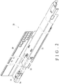
- the slide rail assembly 20 in an embodiment of the present invention is applied to a cabinet 22 having a drawer 24.
- the drawer 24 can be pushed into and pulled out of the cabinet 22 via the slide rail assembly 20.
- FIG. 2 shows the slide rail assembly 20 in an extended state.
- the slide rail assembly 20 includes a first rail 26, a second rail 30, and a third rail 32.
- the first rail 26 is mounted to the cabinet 22 via a mounting portion 28.
- the second rail 30 is movably mounted between the first rail 26 and the third rail 32.
- the second rail 30 and the third rail 32 can be longitudinally displaced relative to the first rail 26.
- the third rail 32 serves to carry the drawer 24.
- a correction mechanism 34 is connected to the first rail 26.
- the correction mechanism 34 in this embodiment is connected to the first rail 26 at a position adjacent to an end portion of the first rail 26 by way of example only and not as a limitation. As the correction mechanism 34 is connected to the first rail 26, the correction mechanism 34 can be viewed as a part of the first rail 26.
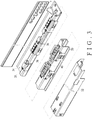
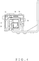
- FIG. 3 and FIG. 4 show the first rail 26, the second rail 30, and the third rail 32 in an exploded view and an assembled view respectively.
- a running carriage 36 is slidably mounted to the first rail 26 and is configured for carrying the second rail 30.
- the running carriage 36 includes at least one roller 38 (or ball) for carrying the second rail 30 and facilitating displacement of the second rail 30 relative to the first rail 26.
- an actuator 40 is connected to the second rail 30.
- the actuator 40 can be, but is not limited to, a projection or a bar-like member.
- the actuator 40 is integrally formed with the second rail 30 and can be viewed as a portion of the second rail 30.
- the correction mechanism 34 includes a base 42 and a pushing member 44.
- the base 42 can be connected (mounted) to and thus fixed in position on the first rail 26 or be integrally formed with the first rail 26.
- the pushing member 44 corresponds to and is movably connected to the base 42.
- the base 42 includes a horizontal portion 46 (which extends in the same direction as the length direction of the first rail 26), an inclined portion 48 inclined at an angle with respect to the horizontal portion 46, and a blocking wall 49 located on the other side of the base 42 (i.e., on a different side from the horizontal portion 46).
- the pushing member 44 includes at least one contact portion, a to-be-blocked portion 51 to be blocked by the blocking wall 49 of the base 42, and an arm portion 53 elastically connected to the pushing member 44.
- the at least one contact portion includes a first contact portion 50a and a second contact portion 50b by way of example.
- both the first contact portion 50a and the second contact portion 50b of the pushing member 44 are in contact with and lie on the horizontal portion 46 of the base 42.
- the pushing member 44 is displaced from the horizontal position P1 to an inclined position (second position) P2 with respect to the base 42, the first contact portion 50a of the pushing member 44 is in contact with and lies on the horizontal portion 46 of the base 42 while the second contact portion 50b of the pushing member 44 is in contact with and lies on the inclined portion 48 of the base 42; as a result, the pushing member 44 is tilted with respect to the base 42 by an angle ⁇ .
- the to-be-blocked portion 51 of the pushing member 44 is blocked by the blocking wall 49 of the base 42 such that the pushing member 44 is kept at the inclined position P2.
- FIG. 7A to FIG. 7C show the pushing member 44 at the inclined position P2 with respect to the base 42.
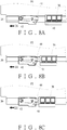
- FIG. 7A to FIG. 7C also show a normal state in which, while the second rail 30 is longitudinally displaced relative to the first rail 26 in a first direction D1 from a retracted position toward an extended position (please note that, in FIG. 7A ⁇ FIG. 7C , the displacement and position of the second rail 30 relative to the first rail 26 are represented by those of the actuator 40), the running carriage 36 is moved together with the second rail (the actuator 40) in the intended (or normal) differential manner with respect to the second rail (the actuator 40).
- the running carriage 36 is synchronously and precisely moved by a distance which is a specific proportion (e.g., one half) of the distance by which the second rail (the actuator 40) is displaced.
- the actuator 40 does not correspond to any portion (e.g., the arm portion 53) of the pushing member 44 and therefore is unable to drive the pushing member 44 while the second rail is displaced relative to the first rail 26 from the retracted position toward the extended position.
- FIG. 8A to FIG. 8C also show the pushing member 44 at the inclined position P2 with respect to the base 42.
- FIG. 8A to FIG. 8C show a normal state in which, while the second rail 30 is longitudinally displaced relative to the first rail 26 in a second direction D2 from the extended position toward the retracted position (please note that, in FIG. 8A ⁇ FIG. 8C , the displacement and position of the second rail 30 relative to the first rail 26 are represented by those of the actuator 40), the running carriage 36 is differentially moved relative to the second rail (the actuator 40) in the intended (or normal) manner.
- FIG. 9A to FIG. 9D wherein the pushing member 44 is initially at the inclined position P2 with respect to the base 42, an abnormal state is shown in which, due to an error in differential movement of the running carriage 36 relative to the second rail (the actuator 40), there is also an error in the position of the running carriage 36 while the running carriage 36 is differentially moved relative to the second rail (the actuator 40).
- the distance by which the running carriage 36 is differentially moved relative to the second rail (the actuator 40) is not the preset proportion of the distance by which the second rail (the actuator 40) is displaced.
- the running carriage 36 contacts the pushing member 44 (see FIG. 9C ) while the second rail (the actuator 40) is retracted from the extended position in the second direction D2.
- the pushing member 44 will be driven by the running carriage 36 such that the second contact portion 50b of the pushing member 44 moves from the inclined portion 48 of the base 42 to the horizontal portion 46 of the base 42; in consequence, the pushing member 44 is displaced relative to the base 42 from the inclined position P2 to the horizontal position P1 (see FIG. 9D ).
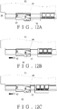
- FIG. 10A to FIG. 10C A detailed description of how to correct the aforesaid abnormal condition is given below with reference to FIG. 10A to FIG. 10C , in which the pushing member 44 is initially at the horizontal position P1 with respect to the base 42, and in which the actuator 40 corresponds to the arm portion 53 of the pushing member 44 at the horizontal position P1.
- the second rail (the actuator 40) is displaced relative to the first rail 26 in the first direction D1 from the retracted position toward the extended position so that, during the displacement, the actuator 40 pushes the arm portion 53 due to the corresponding relationship between the actuator 40 and the pushing member 44.
- the arm portion 53 drives the pushing member 44 from the horizontal position P1 with respect to the base 42 to the inclined position P2, in order for the pushing member 44 to displace the running carriage 36 to a predetermined position (see FIG. 10B ) where the running carriage 36 can be differentially moved relative to the second rail (the actuator 40) in a normal manner.
- the error in differential movement of the running carriage 36 relative to the second rail (the actuator 40) is corrected.
- the actuator 40 will release the pushing member 44 having been driven to the inclined position P2; in consequence, the actuator 40 no longer corresponds to the arm portion 53 of the pushing member 44 and can drive the pushing member 44 no more, thus allowing the running carriage 36 to be differentially moved relative to the second rail (the actuator 40) in a normal manner again.
- the running carriage 36 can be moved relative to the second rail 30 (the actuator 40) in the intended differential manner as the second rail 30 is displaced relative to the first rail 26 in the first direction D1 from the retracted position (please note that, in FIG. 11A ⁇ FIG. 11D , the displacement and position of the second rail 30 relative to the first rail 26 are represented by those of the actuator 40). Should the pushing member 44 be at the horizontal position P1 with respect to the base 42, the actuator 40 will drive the pushing member 44 from the horizontal position P1 to the inclined position P2 during displacement.
- the pushing member 44 at the inclined position P2 is unable to drive the running carriage 36 (i.e., the pushing member 44 will not correct differential movement of the running carriage 36).
- the pushing member 44 is at the horizontal position P1 with respect to the base 42 due to external factors or by accident.
- the second rail 30 can be displaced relative to the first rail 26 in the second direction D2 from the extended position (please note that, in FIG. 12A ⁇ FIG. 12C , the displacement and position of the second rail 30 relative to the first rail 26 are represented by those of the actuator 40) in order for the actuator 40 to push and thereby elastically bend the arm portion 53 of the pushing member 44 (see FIG. 12B ) during the displacement.
- the actuator 40 corresponds to the arm portion 53 of the pushing member 44 again.
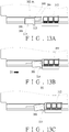
- FIG. 13A to FIG. 13C show the correction mechanism 300 in another embodiment of the present invention.
- the correction mechanism 300 is different from its counterpart in the previous embodiment substantially in that the first rail 26 is directly formed with a horizontal portion 302 and an inclined portion 304.
- the pushing member 306 While the pushing member 306 is displaced, at least one contact portion of the pushing member 306 (e.g., the first contact portion 308 or the second contact portion 310) is in contact with one of the horizontal portion 302 and the inclined portion 304.
- the second rail the actuator 3114 can be displaced in the first direction D1 from the retracted position toward the extended position in order for the actuator 314 to drive the pushing member 306 from the horizontal position P1 to the inclined position P2, and for the pushing member 306 at the inclined position P2 to displace, and thereby correct the differential movement error of, the running carriage 312.
- the actuator 314 releases the pushing member 306 once the pushing member 306 is at the inclined position P2.
Claims (4)
- Ensemble de glissières (20), caractérisée par le fait qu'elle comprend:un premier rail (26) ;un deuxième rail (30) pouvant être déplacé longitudinalement par rapport au premier rail (26) entre une position rétractée et une position étendue;un chariot de roulement (36, 312) monté de manière coulissante sur le premier rail (26), transportant le deuxième rail (30), et déplaçable simultanément avec le deuxième rail (30) d'une manière différentielle par rapport au deuxième rail (30) ;un élément de poussée (44, 306) raccordé de manière mobile entre le premier rail (26) et le deuxième rail (30) et déplaçable entre une position horizontale (P1) et une position inclinée (P2) ; etun déclencheur (40, 314) raccordé au deuxième rail (30), le déclencheur (40, 314) correspondant à l'élément de poussée (44, 306) lorsque l'élément de poussée (44, 306) est en position horizontale (p1);l'élément de poussée (44, 306) en position horizontale (P1) est capable d'être entraîné par le déclencheur (40, 314) pour déplacer la position inclinée (P2) et par delà déplacer le chariot de roulement (36, 312) vers une position,en cas d'erreur dans le mouvement différentiel du chariot de roulement (36, 312), le déclencheur (40, 314) entraîne l'élément de poussée (44, 306) alors que le deuxième rail (30) est déplacé de la position rétractée vers la position étendue, de sorte que l'élément de poussée (44, 306) est déplacé de la position horizontale (P1) vers la position inclinée (P2) et déplace le chariot de roulement (36, 312) pour corriger l'erreur, le déclencheur (40, 314) libérant l'élément de poussée (44, 306) une fois l'élément de poussée (44, 306) en position inclinée (P2),caractérisé en ce queun mécanisme de correction (34, 300) est raccordé au premier rail (26), le mécanisme de correction (34, 300) comprenant l'élément de poussée (44, 306),l'élément de poussée (44, 306) est raccordé de manière mobile au premier rail (26) ou à une base (42) raccordée au premier rail (26); etle premier rail (26) ou la base (42) comprennent une partie horizontale (46, 302) et une partie inclinée (48, 304) inclinée par rapport à la la partie horizontale (46, 302), et l'élément de poussée (44, 306) est déplaçable entre la partie horizontale (46, 302) et la partie inclinée (48, 304), etl'élément de poussée (44, 306) comprend en outre au moins une partie de contact (50a, 50b, 308, 310) pour un contact avec soit la partie horizontale (46, 302) soit la partie inclinée (48, 304) du premier rail (26) ou la base (42) lorsque l'élément de poussée (44, 306) est déplacé par rapport au premier rail (26) ou à la base (42).
- L'ensemble de glissières (20) selon la revendication 1, caractérisée par le fait que le déclencheur (40, 314) fait partie intégrante du deuxième rail (30).
- L'ensemble de glissières (20) selon l'une des revendications 1-2, caractérisée par le fait que le chariot de roulement (36, 312) transporte le deuxième rail (30) via au moins une roulette (38).
- L'ensemble de glissières (20) selon l'une des revendications 1-3, caractérisée par le fait qu'elle comprend en outre un troisième rail (32) et étant applicable à une armoire (22), l'armoire (22) comportant un tiroir (24), dans lequel le premier rail (26) est montable sur l'armoire (22), le deuxième rail (30) est monté de manière mobile entre le premier rail (26) et le troisième rail (32), et le troisième rail (32) transporte le tiroir (24).
Priority Applications (1)
| Application Number | Priority Date | Filing Date | Title |
|---|---|---|---|
| EP15155567.9A EP3058847B1 (fr) | 2015-02-18 | 2015-02-18 | Ensemble de rail de glissement |
Applications Claiming Priority (1)
| Application Number | Priority Date | Filing Date | Title |
|---|---|---|---|
| EP15155567.9A EP3058847B1 (fr) | 2015-02-18 | 2015-02-18 | Ensemble de rail de glissement |
Publications (2)
| Publication Number | Publication Date |
|---|---|
| EP3058847A1 EP3058847A1 (fr) | 2016-08-24 |
| EP3058847B1 true EP3058847B1 (fr) | 2017-04-05 |
Family
ID=52477664
Family Applications (1)
| Application Number | Title | Priority Date | Filing Date |
|---|---|---|---|
| EP15155567.9A Active EP3058847B1 (fr) | 2015-02-18 | 2015-02-18 | Ensemble de rail de glissement |
Country Status (1)
| Country | Link |
|---|---|
| EP (1) | EP3058847B1 (fr) |
Families Citing this family (2)
| Publication number | Priority date | Publication date | Assignee | Title |
|---|---|---|---|---|
| AT519982B1 (de) * | 2017-08-17 | 2018-12-15 | Blum Gmbh Julius | Schubladenausziehführung |
| TWI740796B (zh) * | 2021-03-22 | 2021-09-21 | 南俊國際股份有限公司 | 伸縮滑軌支撐滑輪結構 |
Family Cites Families (2)
| Publication number | Priority date | Publication date | Assignee | Title |
|---|---|---|---|---|
| AT6364U1 (de) | 2002-08-29 | 2003-09-25 | Blum Gmbh Julius | Ausziehführungsgarnitur für schubladen |
| AT505120B1 (de) * | 2007-05-07 | 2012-04-15 | Blum Gmbh Julius | Ausziehführung für schubladen |
-
2015
- 2015-02-18 EP EP15155567.9A patent/EP3058847B1/fr active Active
Non-Patent Citations (1)
| Title |
|---|
| None * |
Also Published As
| Publication number | Publication date |
|---|---|
| EP3058847A1 (fr) | 2016-08-24 |
Similar Documents
| Publication | Publication Date | Title |
|---|---|---|
| US9498061B2 (en) | Slide rail assembly | |
| EP3175736B1 (fr) | Assemblage de glissieres | |
| EP3387952B1 (fr) | Ensemble de couloir coulissant | |
| EP3143901B1 (fr) | Glissière télescopique | |
| EP3398481B1 (fr) | Ensemble de rails de glissement | |
| EP3461244B1 (fr) | Ensemble rail coulissant et son mécanisme de guidage | |
| EP3292789B1 (fr) | Ensemble de rail coulissant | |
| EP3387950B1 (fr) | Ensemble de rails de glissement | |
| EP3537857B1 (fr) | Ensemble rail coulissant et son dispositif de support | |
| EP3440961B1 (fr) | Ensemble rail de glissière et kit rail de celui-ci | |
| JP2019005548A (ja) | スライドレールアセンブリ | |
| EP3058847B1 (fr) | Ensemble de rail de glissement | |
| EP3056116B1 (fr) | Ensemble de rail de glissement | |
| EP3378354A1 (fr) | Agencement d'engrenages pour système de meubles | |
| US9526334B2 (en) | Slide rail assembly | |
| CN107581807B (zh) | 安装机构 | |
| EP3824764A1 (fr) | Ensemble rail coulissant et son dispositif de retour | |
| TWI522065B (zh) | 滑軌總成 | |
| US10888158B1 (en) | Slide rail assembly | |
| JP6342688B2 (ja) | スライドレールのストッパー装置 | |
| TWI517812B (zh) | 滑軌總成 | |
| CN109419190B (zh) | 滑轨总成及其滑轨套件 | |
| US10973322B1 (en) | Slide rail assembly | |
| CN112971407B (zh) | 滑轨总成 | |
| CN112932117B (zh) | 滑轨总成及其回归装置 |
Legal Events
| Date | Code | Title | Description |
|---|---|---|---|
| PUAI | Public reference made under article 153(3) epc to a published international application that has entered the european phase |
Free format text: ORIGINAL CODE: 0009012 |
|
| 17P | Request for examination filed |
Effective date: 20160504 |
|
| AK | Designated contracting states |
Kind code of ref document: A1 Designated state(s): AL AT BE BG CH CY CZ DE DK EE ES FI FR GB GR HR HU IE IS IT LI LT LU LV MC MK MT NL NO PL PT RO RS SE SI SK SM TR |
|
| AX | Request for extension of the european patent |
Extension state: BA ME |
|
| RIC1 | Information provided on ipc code assigned before grant |
Ipc: A47B 88/10 20060101AFI20160829BHEP |
|
| GRAP | Despatch of communication of intention to grant a patent |
Free format text: ORIGINAL CODE: EPIDOSNIGR1 |
|
| INTG | Intention to grant announced |
Effective date: 20161010 |
|
| GRAS | Grant fee paid |
Free format text: ORIGINAL CODE: EPIDOSNIGR3 |
|
| REG | Reference to a national code |
Ref country code: DE Ref legal event code: R079 Ref document number: 602015002071 Country of ref document: DE Free format text: PREVIOUS MAIN CLASS: A47B0088100000 Ipc: A47B0088493000 |
|
| GRAA | (expected) grant |
Free format text: ORIGINAL CODE: 0009210 |
|
| AK | Designated contracting states |
Kind code of ref document: B1 Designated state(s): AL AT BE BG CH CY CZ DE DK EE ES FI FR GB GR HR HU IE IS IT LI LT LU LV MC MK MT NL NO PL PT RO RS SE SI SK SM TR |
|
| REG | Reference to a national code |
Ref country code: GB Ref legal event code: FG4D |
|
| RIC1 | Information provided on ipc code assigned before grant |
Ipc: A47B 88/493 20170101AFI20170301BHEP |
|
| REG | Reference to a national code |
Ref country code: CH Ref legal event code: EP |
|
| REG | Reference to a national code |
Ref country code: AT Ref legal event code: REF Ref document number: 880954 Country of ref document: AT Kind code of ref document: T Effective date: 20170415 |
|
| REG | Reference to a national code |
Ref country code: IE Ref legal event code: FG4D |
|
| REG | Reference to a national code |
Ref country code: DE Ref legal event code: R096 Ref document number: 602015002071 Country of ref document: DE |
|
| REG | Reference to a national code |
Ref country code: NL Ref legal event code: MP Effective date: 20170405 |
|
| REG | Reference to a national code |
Ref country code: LT Ref legal event code: MG4D |
|
| REG | Reference to a national code |
Ref country code: AT Ref legal event code: MK05 Ref document number: 880954 Country of ref document: AT Kind code of ref document: T Effective date: 20170405 |
|
| PG25 | Lapsed in a contracting state [announced via postgrant information from national office to epo] |
Ref country code: NL Free format text: LAPSE BECAUSE OF FAILURE TO SUBMIT A TRANSLATION OF THE DESCRIPTION OR TO PAY THE FEE WITHIN THE PRESCRIBED TIME-LIMIT Effective date: 20170405 |
|
| PG25 | Lapsed in a contracting state [announced via postgrant information from national office to epo] |
Ref country code: FI Free format text: LAPSE BECAUSE OF FAILURE TO SUBMIT A TRANSLATION OF THE DESCRIPTION OR TO PAY THE FEE WITHIN THE PRESCRIBED TIME-LIMIT Effective date: 20170405 Ref country code: AT Free format text: LAPSE BECAUSE OF FAILURE TO SUBMIT A TRANSLATION OF THE DESCRIPTION OR TO PAY THE FEE WITHIN THE PRESCRIBED TIME-LIMIT Effective date: 20170405 Ref country code: LT Free format text: LAPSE BECAUSE OF FAILURE TO SUBMIT A TRANSLATION OF THE DESCRIPTION OR TO PAY THE FEE WITHIN THE PRESCRIBED TIME-LIMIT Effective date: 20170405 Ref country code: ES Free format text: LAPSE BECAUSE OF FAILURE TO SUBMIT A TRANSLATION OF THE DESCRIPTION OR TO PAY THE FEE WITHIN THE PRESCRIBED TIME-LIMIT Effective date: 20170405 Ref country code: NO Free format text: LAPSE BECAUSE OF FAILURE TO SUBMIT A TRANSLATION OF THE DESCRIPTION OR TO PAY THE FEE WITHIN THE PRESCRIBED TIME-LIMIT Effective date: 20170705 Ref country code: HR Free format text: LAPSE BECAUSE OF FAILURE TO SUBMIT A TRANSLATION OF THE DESCRIPTION OR TO PAY THE FEE WITHIN THE PRESCRIBED TIME-LIMIT Effective date: 20170405 |
|
| PG25 | Lapsed in a contracting state [announced via postgrant information from national office to epo] |
Ref country code: SE Free format text: LAPSE BECAUSE OF FAILURE TO SUBMIT A TRANSLATION OF THE DESCRIPTION OR TO PAY THE FEE WITHIN THE PRESCRIBED TIME-LIMIT Effective date: 20170405 Ref country code: BG Free format text: LAPSE BECAUSE OF FAILURE TO SUBMIT A TRANSLATION OF THE DESCRIPTION OR TO PAY THE FEE WITHIN THE PRESCRIBED TIME-LIMIT Effective date: 20170705 Ref country code: LV Free format text: LAPSE BECAUSE OF FAILURE TO SUBMIT A TRANSLATION OF THE DESCRIPTION OR TO PAY THE FEE WITHIN THE PRESCRIBED TIME-LIMIT Effective date: 20170405 Ref country code: PL Free format text: LAPSE BECAUSE OF FAILURE TO SUBMIT A TRANSLATION OF THE DESCRIPTION OR TO PAY THE FEE WITHIN THE PRESCRIBED TIME-LIMIT Effective date: 20170405 Ref country code: RS Free format text: LAPSE BECAUSE OF FAILURE TO SUBMIT A TRANSLATION OF THE DESCRIPTION OR TO PAY THE FEE WITHIN THE PRESCRIBED TIME-LIMIT Effective date: 20170405 Ref country code: IS Free format text: LAPSE BECAUSE OF FAILURE TO SUBMIT A TRANSLATION OF THE DESCRIPTION OR TO PAY THE FEE WITHIN THE PRESCRIBED TIME-LIMIT Effective date: 20170805 |
|
| REG | Reference to a national code |
Ref country code: DE Ref legal event code: R097 Ref document number: 602015002071 Country of ref document: DE |
|
| PG25 | Lapsed in a contracting state [announced via postgrant information from national office to epo] |
Ref country code: CZ Free format text: LAPSE BECAUSE OF FAILURE TO SUBMIT A TRANSLATION OF THE DESCRIPTION OR TO PAY THE FEE WITHIN THE PRESCRIBED TIME-LIMIT Effective date: 20170405 Ref country code: EE Free format text: LAPSE BECAUSE OF FAILURE TO SUBMIT A TRANSLATION OF THE DESCRIPTION OR TO PAY THE FEE WITHIN THE PRESCRIBED TIME-LIMIT Effective date: 20170405 Ref country code: RO Free format text: LAPSE BECAUSE OF FAILURE TO SUBMIT A TRANSLATION OF THE DESCRIPTION OR TO PAY THE FEE WITHIN THE PRESCRIBED TIME-LIMIT Effective date: 20170405 Ref country code: DK Free format text: LAPSE BECAUSE OF FAILURE TO SUBMIT A TRANSLATION OF THE DESCRIPTION OR TO PAY THE FEE WITHIN THE PRESCRIBED TIME-LIMIT Effective date: 20170405 Ref country code: SK Free format text: LAPSE BECAUSE OF FAILURE TO SUBMIT A TRANSLATION OF THE DESCRIPTION OR TO PAY THE FEE WITHIN THE PRESCRIBED TIME-LIMIT Effective date: 20170405 |
|
| PLBE | No opposition filed within time limit |
Free format text: ORIGINAL CODE: 0009261 |
|
| STAA | Information on the status of an ep patent application or granted ep patent |
Free format text: STATUS: NO OPPOSITION FILED WITHIN TIME LIMIT |
|
| PG25 | Lapsed in a contracting state [announced via postgrant information from national office to epo] |
Ref country code: SM Free format text: LAPSE BECAUSE OF FAILURE TO SUBMIT A TRANSLATION OF THE DESCRIPTION OR TO PAY THE FEE WITHIN THE PRESCRIBED TIME-LIMIT Effective date: 20170405 Ref country code: IT Free format text: LAPSE BECAUSE OF FAILURE TO SUBMIT A TRANSLATION OF THE DESCRIPTION OR TO PAY THE FEE WITHIN THE PRESCRIBED TIME-LIMIT Effective date: 20170405 |
|
| 26N | No opposition filed |
Effective date: 20180108 |
|
| REG | Reference to a national code |
Ref country code: CH Ref legal event code: PL |
|
| PG25 | Lapsed in a contracting state [announced via postgrant information from national office to epo] |
Ref country code: MC Free format text: LAPSE BECAUSE OF FAILURE TO SUBMIT A TRANSLATION OF THE DESCRIPTION OR TO PAY THE FEE WITHIN THE PRESCRIBED TIME-LIMIT Effective date: 20170405 |
|
| REG | Reference to a national code |
Ref country code: BE Ref legal event code: MM Effective date: 20180228 |
|
| PG25 | Lapsed in a contracting state [announced via postgrant information from national office to epo] |
Ref country code: LI Free format text: LAPSE BECAUSE OF NON-PAYMENT OF DUE FEES Effective date: 20180228 Ref country code: CH Free format text: LAPSE BECAUSE OF NON-PAYMENT OF DUE FEES Effective date: 20180228 Ref country code: LU Free format text: LAPSE BECAUSE OF NON-PAYMENT OF DUE FEES Effective date: 20180218 |
|
| REG | Reference to a national code |
Ref country code: FR Ref legal event code: ST Effective date: 20181031 |
|
| PG25 | Lapsed in a contracting state [announced via postgrant information from national office to epo] |
Ref country code: FR Free format text: LAPSE BECAUSE OF NON-PAYMENT OF DUE FEES Effective date: 20180228 Ref country code: BE Free format text: LAPSE BECAUSE OF NON-PAYMENT OF DUE FEES Effective date: 20180228 |
|
| PG25 | Lapsed in a contracting state [announced via postgrant information from national office to epo] |
Ref country code: MT Free format text: LAPSE BECAUSE OF NON-PAYMENT OF DUE FEES Effective date: 20180218 |
|
| PG25 | Lapsed in a contracting state [announced via postgrant information from national office to epo] |
Ref country code: TR Free format text: LAPSE BECAUSE OF FAILURE TO SUBMIT A TRANSLATION OF THE DESCRIPTION OR TO PAY THE FEE WITHIN THE PRESCRIBED TIME-LIMIT Effective date: 20170405 |
|
| PG25 | Lapsed in a contracting state [announced via postgrant information from national office to epo] |
Ref country code: PT Free format text: LAPSE BECAUSE OF FAILURE TO SUBMIT A TRANSLATION OF THE DESCRIPTION OR TO PAY THE FEE WITHIN THE PRESCRIBED TIME-LIMIT Effective date: 20170405 |
|
| PG25 | Lapsed in a contracting state [announced via postgrant information from national office to epo] |
Ref country code: CY Free format text: LAPSE BECAUSE OF FAILURE TO SUBMIT A TRANSLATION OF THE DESCRIPTION OR TO PAY THE FEE WITHIN THE PRESCRIBED TIME-LIMIT Effective date: 20170405 Ref country code: MK Free format text: LAPSE BECAUSE OF NON-PAYMENT OF DUE FEES Effective date: 20170405 Ref country code: HU Free format text: LAPSE BECAUSE OF FAILURE TO SUBMIT A TRANSLATION OF THE DESCRIPTION OR TO PAY THE FEE WITHIN THE PRESCRIBED TIME-LIMIT; INVALID AB INITIO Effective date: 20150218 Ref country code: GR Free format text: LAPSE BECAUSE OF FAILURE TO SUBMIT A TRANSLATION OF THE DESCRIPTION OR TO PAY THE FEE WITHIN THE PRESCRIBED TIME-LIMIT Effective date: 20170405 |
|
| PG25 | Lapsed in a contracting state [announced via postgrant information from national office to epo] |
Ref country code: AL Free format text: LAPSE BECAUSE OF FAILURE TO SUBMIT A TRANSLATION OF THE DESCRIPTION OR TO PAY THE FEE WITHIN THE PRESCRIBED TIME-LIMIT Effective date: 20170405 |
|
| PG25 | Lapsed in a contracting state [announced via postgrant information from national office to epo] |
Ref country code: SI Free format text: LAPSE BECAUSE OF NON-PAYMENT OF DUE FEES Effective date: 20180218 |
|
| PGFP | Annual fee paid to national office [announced via postgrant information from national office to epo] |
Ref country code: IE Payment date: 20230207 Year of fee payment: 9 |
|
| PGFP | Annual fee paid to national office [announced via postgrant information from national office to epo] |
Ref country code: GB Payment date: 20230207 Year of fee payment: 9 Ref country code: DE Payment date: 20230209 Year of fee payment: 9 |
|
| PGFP | Annual fee paid to national office [announced via postgrant information from national office to epo] |
Ref country code: IE Payment date: 20240206 Year of fee payment: 10 |