EP3058192B1 - Moteur thermique à combustion basée sur la compression isotherme - Google Patents
Moteur thermique à combustion basée sur la compression isotherme Download PDFInfo
- Publication number
- EP3058192B1 EP3058192B1 EP14864879.3A EP14864879A EP3058192B1 EP 3058192 B1 EP3058192 B1 EP 3058192B1 EP 14864879 A EP14864879 A EP 14864879A EP 3058192 B1 EP3058192 B1 EP 3058192B1
- Authority
- EP
- European Patent Office
- Prior art keywords
- volume
- combustion engine
- engine
- fuel
- cylinder
- Prior art date
- Legal status (The legal status is an assumption and is not a legal conclusion. Google has not performed a legal analysis and makes no representation as to the accuracy of the status listed.)
- Active
Links
- 238000002485 combustion reaction Methods 0.000 title claims description 145
- 230000006835 compression Effects 0.000 title claims description 50
- 238000007906 compression Methods 0.000 title claims description 50
- 239000000446 fuel Substances 0.000 claims description 126
- 238000000034 method Methods 0.000 claims description 29
- 238000002347 injection Methods 0.000 claims description 26
- 239000007924 injection Substances 0.000 claims description 26
- 230000004044 response Effects 0.000 claims description 5
- 238000012544 monitoring process Methods 0.000 claims description 4
- 239000003570 air Substances 0.000 description 136
- 239000000203 mixture Substances 0.000 description 19
- CURLTUGMZLYLDI-UHFFFAOYSA-N Carbon dioxide Chemical compound O=C=O CURLTUGMZLYLDI-UHFFFAOYSA-N 0.000 description 14
- 238000013461 design Methods 0.000 description 9
- 230000001133 acceleration Effects 0.000 description 7
- 229910002092 carbon dioxide Inorganic materials 0.000 description 7
- 239000001569 carbon dioxide Substances 0.000 description 7
- 239000007789 gas Substances 0.000 description 7
- 239000012080 ambient air Substances 0.000 description 5
- 230000008901 benefit Effects 0.000 description 5
- 230000009919 sequestration Effects 0.000 description 5
- 230000003068 static effect Effects 0.000 description 5
- 239000002918 waste heat Substances 0.000 description 4
- OKTJSMMVPCPJKN-UHFFFAOYSA-N Carbon Chemical compound [C] OKTJSMMVPCPJKN-UHFFFAOYSA-N 0.000 description 3
- 229910052799 carbon Inorganic materials 0.000 description 3
- 238000010276 construction Methods 0.000 description 3
- 230000001419 dependent effect Effects 0.000 description 3
- 238000010586 diagram Methods 0.000 description 3
- 230000009467 reduction Effects 0.000 description 3
- 230000001172 regenerating effect Effects 0.000 description 3
- 230000003197 catalytic effect Effects 0.000 description 2
- 230000008859 change Effects 0.000 description 2
- 230000003247 decreasing effect Effects 0.000 description 2
- 238000010304 firing Methods 0.000 description 2
- 238000010438 heat treatment Methods 0.000 description 2
- 229910044991 metal oxide Inorganic materials 0.000 description 2
- 150000004706 metal oxides Chemical class 0.000 description 2
- 238000005086 pumping Methods 0.000 description 2
- 230000002000 scavenging effect Effects 0.000 description 2
- 238000012546 transfer Methods 0.000 description 2
- 229920000049 Carbon (fiber) Polymers 0.000 description 1
- 230000009286 beneficial effect Effects 0.000 description 1
- 239000002551 biofuel Substances 0.000 description 1
- 239000004917 carbon fiber Substances 0.000 description 1
- 239000002131 composite material Substances 0.000 description 1
- 238000001816 cooling Methods 0.000 description 1
- 230000008878 coupling Effects 0.000 description 1
- 238000010168 coupling process Methods 0.000 description 1
- 238000005859 coupling reaction Methods 0.000 description 1
- 238000005474 detonation Methods 0.000 description 1
- 230000009977 dual effect Effects 0.000 description 1
- 230000006698 induction Effects 0.000 description 1
- 239000007788 liquid Substances 0.000 description 1
- VNWKTOKETHGBQD-UHFFFAOYSA-N methane Chemical compound C VNWKTOKETHGBQD-UHFFFAOYSA-N 0.000 description 1
- 238000013021 overheating Methods 0.000 description 1
- 238000006467 substitution reaction Methods 0.000 description 1
- 238000011144 upstream manufacturing Methods 0.000 description 1
Images


Classifications
-
- F—MECHANICAL ENGINEERING; LIGHTING; HEATING; WEAPONS; BLASTING
- F02—COMBUSTION ENGINES; HOT-GAS OR COMBUSTION-PRODUCT ENGINE PLANTS
- F02B—INTERNAL-COMBUSTION PISTON ENGINES; COMBUSTION ENGINES IN GENERAL
- F02B21/00—Engines characterised by air-storage chambers
-
- F—MECHANICAL ENGINEERING; LIGHTING; HEATING; WEAPONS; BLASTING
- F02—COMBUSTION ENGINES; HOT-GAS OR COMBUSTION-PRODUCT ENGINE PLANTS
- F02D—CONTROLLING COMBUSTION ENGINES
- F02D13/00—Controlling the engine output power by varying inlet or exhaust valve operating characteristics, e.g. timing
- F02D13/02—Controlling the engine output power by varying inlet or exhaust valve operating characteristics, e.g. timing during engine operation
- F02D13/0276—Actuation of an additional valve for a special application, e.g. for decompression, exhaust gas recirculation or cylinder scavenging
-
- F—MECHANICAL ENGINEERING; LIGHTING; HEATING; WEAPONS; BLASTING
- F02—COMBUSTION ENGINES; HOT-GAS OR COMBUSTION-PRODUCT ENGINE PLANTS
- F02B—INTERNAL-COMBUSTION PISTON ENGINES; COMBUSTION ENGINES IN GENERAL
- F02B29/00—Engines characterised by provision for charging or scavenging not provided for in groups F02B25/00, F02B27/00 or F02B33/00 - F02B39/00; Details thereof
- F02B29/04—Cooling of air intake supply
-
- F—MECHANICAL ENGINEERING; LIGHTING; HEATING; WEAPONS; BLASTING
- F02—COMBUSTION ENGINES; HOT-GAS OR COMBUSTION-PRODUCT ENGINE PLANTS
- F02B—INTERNAL-COMBUSTION PISTON ENGINES; COMBUSTION ENGINES IN GENERAL
- F02B33/00—Engines characterised by provision of pumps for charging or scavenging
-
- F—MECHANICAL ENGINEERING; LIGHTING; HEATING; WEAPONS; BLASTING
- F02—COMBUSTION ENGINES; HOT-GAS OR COMBUSTION-PRODUCT ENGINE PLANTS
- F02B—INTERNAL-COMBUSTION PISTON ENGINES; COMBUSTION ENGINES IN GENERAL
- F02B33/00—Engines characterised by provision of pumps for charging or scavenging
- F02B33/44—Passages conducting the charge from the pump to the engine inlet, e.g. reservoirs
-
- F—MECHANICAL ENGINEERING; LIGHTING; HEATING; WEAPONS; BLASTING
- F02—COMBUSTION ENGINES; HOT-GAS OR COMBUSTION-PRODUCT ENGINE PLANTS
- F02B—INTERNAL-COMBUSTION PISTON ENGINES; COMBUSTION ENGINES IN GENERAL
- F02B37/00—Engines characterised by provision of pumps driven at least for part of the time by exhaust
- F02B37/04—Engines with exhaust drive and other drive of pumps, e.g. with exhaust-driven pump and mechanically-driven second pump
-
- F—MECHANICAL ENGINEERING; LIGHTING; HEATING; WEAPONS; BLASTING
- F02—COMBUSTION ENGINES; HOT-GAS OR COMBUSTION-PRODUCT ENGINE PLANTS
- F02B—INTERNAL-COMBUSTION PISTON ENGINES; COMBUSTION ENGINES IN GENERAL
- F02B2275/00—Other engines, components or details, not provided for in other groups of this subclass
- F02B2275/14—Direct injection into combustion chamber
-
- F—MECHANICAL ENGINEERING; LIGHTING; HEATING; WEAPONS; BLASTING
- F02—COMBUSTION ENGINES; HOT-GAS OR COMBUSTION-PRODUCT ENGINE PLANTS
- F02B—INTERNAL-COMBUSTION PISTON ENGINES; COMBUSTION ENGINES IN GENERAL
- F02B3/00—Engines characterised by air compression and subsequent fuel addition
- F02B3/06—Engines characterised by air compression and subsequent fuel addition with compression ignition
- F02B3/08—Methods of operating
-
- F—MECHANICAL ENGINEERING; LIGHTING; HEATING; WEAPONS; BLASTING
- F02—COMBUSTION ENGINES; HOT-GAS OR COMBUSTION-PRODUCT ENGINE PLANTS
- F02D—CONTROLLING COMBUSTION ENGINES
- F02D33/00—Controlling delivery of fuel or combustion-air, not otherwise provided for
- F02D33/003—Controlling the feeding of liquid fuel from storage containers to carburettors or fuel-injection apparatus ; Failure or leakage prevention; Diagnosis or detection of failure; Arrangement of sensors in the fuel system; Electric wiring; Electrostatic discharge
- F02D33/006—Controlling the feeding of liquid fuel from storage containers to carburettors or fuel-injection apparatus ; Failure or leakage prevention; Diagnosis or detection of failure; Arrangement of sensors in the fuel system; Electric wiring; Electrostatic discharge depending on engine operating conditions, e.g. start, stop or ambient conditions
-
- F—MECHANICAL ENGINEERING; LIGHTING; HEATING; WEAPONS; BLASTING
- F02—COMBUSTION ENGINES; HOT-GAS OR COMBUSTION-PRODUCT ENGINE PLANTS
- F02M—SUPPLYING COMBUSTION ENGINES IN GENERAL WITH COMBUSTIBLE MIXTURES OR CONSTITUENTS THEREOF
- F02M23/00—Apparatus for adding secondary air to fuel-air mixture
- F02M2023/008—Apparatus for adding secondary air to fuel-air mixture by injecting compressed air directly into the combustion chamber
-
- Y—GENERAL TAGGING OF NEW TECHNOLOGICAL DEVELOPMENTS; GENERAL TAGGING OF CROSS-SECTIONAL TECHNOLOGIES SPANNING OVER SEVERAL SECTIONS OF THE IPC; TECHNICAL SUBJECTS COVERED BY FORMER USPC CROSS-REFERENCE ART COLLECTIONS [XRACs] AND DIGESTS
- Y02—TECHNOLOGIES OR APPLICATIONS FOR MITIGATION OR ADAPTATION AGAINST CLIMATE CHANGE
- Y02T—CLIMATE CHANGE MITIGATION TECHNOLOGIES RELATED TO TRANSPORTATION
- Y02T10/00—Road transport of goods or passengers
- Y02T10/10—Internal combustion engine [ICE] based vehicles
- Y02T10/12—Improving ICE efficiencies
Definitions
- Traditional combustion engines include an intake stroke followed by a compression stroke. Generally, a mixture of air and fuel is introduced into a combustion chamber of the engine during the intake stroke and thereafter compressed by a piston during the compression stroke. Compression of the air/fuel mixture significantly increases the temperature and pressure of the mixture. Autoignition may occur when the compressed air/fuel mixture reaches a temperature that causes it to spontaneously ignite prior to a spark plug firing to ignite the air/fuel mixture and may cause damage to the engine. Accordingly, design features of traditional combustion engines such as static compression ratio, forced induction capacity, power density, fuel economy, and fueling options are constrained by the limits of autoignition.
- JP H07-54659 discloses an air intake, isothermal compression heat engine.
- the engine comprises a combustor which is connected to a compressor by a combination of an air feeding pipe, a pressure accumulating tank, an exhaust pipe, an air fuel mixing device and an air feeding valve.
- US 2007/0157894 discloses a split-cycle air hybrid engine which operatively connects an air reservoir to a split-cycle engine.
- WO 01/16470 discloses an internal combustion engine and method in which separate compression and power cylinders are used and regenerator or a pair of regenerators is mounted between them to provide heat for hot-air ignition.
- the invention is directed to an isothermal compression based combustion engine according to claim 1 and to a method of operating an isothermal compression based combustion engine according to claim 2.
- the IsoC engine may inject ambient temperature compressed air into a combustion engine immediately prior to a combustion event in order to increase the efficiency of the engine.
- the IsoC engine may also comprise a turbocharger coupled to an isothermal compressor and the exhaust stream from the combustion engine to increase airflow into the compressor.
- the IsoC engine may further comprise capacitance air tanks that may be employed to drive the combustion engine pistons and allow combustion to be selectively terminated to increase fuel efficiency and curtail emissions.
- the IsoC engine may also be compatible with regenerative braking.
- the IsoC engine may also employ lean burns (e.g.
- the IsoC engine may also comprise a carbon sequestration filter to further decrease net carbon emissions. Additionally, the components supporting IsoC engine efficiency may provide the hardware necessary to operate the engine as a dual-drive hybrid platform. The high pressure pneumatic components of the IsoC engine that facilitate thermal efficiency may also allow the engine to operate as a zero-emissions air motor using no combustion at all.
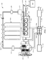
- an isothermal compression based combustion (IsoC) engine 100 is shown according to an embodiment of the disclosure.
- the IsoC engine 100 is a combustion engine that continuously substitutes an isothermally-cooled compression charge (the charge being at, or very near ambient temperature) for the hot adiabatic compression leveraged in traditional combustion engine cycles.
- the absence of compression heat inside the IsoC engine 100 cylinders 156 prior to spark-ignition substantially eliminates autoignition as a design boundary for the isothermally compressed combustion engine.
- the IsoC engine 100 comprises an intercooled, multistage compressor 102 configured to collect and compress ambient air while rejecting the heat of compression, at least one capacitance tank 104 configured to store the cooled compressed air, and a combustion engine 106 configured to power a drive drain or other apparatus as a result of injecting isothermally compressed air from the at least one capacitance tank 104 and/or fuel supplied by the fuel system 140 into a plurality of cylinders 156 of the combustion engine 106.
- the IsoC engine 100 may also comprise a turbocharger 108 configured to increase the flow of air to the compressor 102.
- the compressor 102 is configured to isothermally compress air and pass the compressed air to at least one capacitance tank 104 coupled to the compressor 102.
- the compressor 102 is generally configured as an intercooled, multistage piston compressor.
- the compressor 102 may be a scroll-type compressor.
- the compressor 102 may be a rotary-type compressor.
- the compressor 102 may be any other type of suitable compressor capable of increasing the pressure of a body of air received by the compressor 102.
- the compressor 102 comprises at least one compressor fan 138 and at least one heat exchanger 158 configured to dissipate heat caused by compressing the air within the compressor 102.
- the compressor fan 138 is configured to generate a passing airflow across the heat exchanger 158 to facilitate heat transfer between the passing airflow and the heat exchanger 158.
- the heat exchanger 158 may include fins, heat sinks, intercoolers, and/or any combination of fins, heat sinks, intercoolers, and other features that are configured to promote heat transfer between a passing airflow and the heat exchanger 158.
- heat rejected from the heat exchanger 158 of the compressor 102 may be purposed to provide cabin heating, oil heating in cold climates, and/or other ancillary uses.
- the heat exchanger 158 of the compressor 102 may also be configured for liquid cooling.
- the compressor 102 By rejecting heat caused by the compression of air within the compressor 102, the compressor 102 is capable of isothermally compressing the air within the compressor 102.
- the isothermally compressed air may have a temperature that is substantially similar to the temperature of the ambient air entering the compressor 102.
- the passing airflow may dissipate the heat into ambient air or alternatively be diverted through a compressor exhaust 132.
- the compressor exhaust 132 may be coupled to a hot side 108b of the turbocharger 108.
- heat energy rejected by the heat exchanger 158 of the compressor 102 may be recovered by the turbocharger 108 to further increase the efficiency of the compressor 102 and/or the IsoC engine 100.
- the compressor 102 supplies isothermally compressed air to the at least one capacitance tank 104 through a line dryer 112 disposed between the compressor 102 and the at least one capacitance tank 104.
- the line dryer 112 is configured to remove moisture from the isothermally compressed air coming from the compressor 102.
- a check valve 114 may also be disposed between the compressor 102 and the at least one capacitance tank 104. The check valve is configured to prevent isothermally compressed air from a downstream side closer to the at least one capacitance tank 104 from flowing in an upstream direction towards the compressor 102.
- an external fill port 116 may be disposed between the check valve 114 and the at least one capacitance tank 104.
- the external fill port 116 is configured to couple to an external compressed air source to allow the at least one capacitance tank 104 to receive compressed air through the external fill port 116 from the external compressed air source. Further, the check valve 114 may also prevent compressed air received from an external compressed air source through the external fill port 116 to flow towards the compressor 102.
- the IsoC engine 100 is disclosed as having at least one capacitance tank 104, it will be appreciated that the IsoC engine 100 may include a plurality of capacitance tanks 104.
- the capacitance tanks 104 are generally configured to store isothermally compressed air received from the compressor 102. Further, the capacitance tanks 104 are configured to supply a charge of isothermally compressed air to the combustion engine 106.
- the capacitance tanks 104 may generally comprise a lightweight, high-strength construction. In some embodiments, the capacitance tanks 104 may comprise a carbon fiber composite construction.
- the capacitance tanks 104 may be charged to a pressure of up to about 3,447 kPa (500 pounds per square inch, psi), up to about 6,895 kPa (1,000 psi), up to about 13,790 kPa (2,000 psi), up to about 20,684 kPa (3,000 psi), up to about 27,579 kPa (4,000 psi), and/or up to about 34,474 kPa (5,000 psi).
- the IsoC engine 100 includes a shutoff valve 118.
- the shutoff valve 118 is selectively operable to substantially restrict and/or substantially prevent compressed air stored in the capacitance tanks 104 from passing into the combustion engine 106.
- the shutoff valve 118 may be a manually-controlled shutoff valve.
- the shutoff valve 118 may be an electronically-controlled valve that may be selectively operated to allow or restrict the flow of compressed air from the capacitance tanks 104 to the combustion engine 106.
- the shutoff valve 118 may be pneumatically actuated by a sudden change in pressure as a fail-safe emergency cutoff.
- the IsoC engine 100 may also include a carbon dioxide sequestration filter 120 between the capacitance tanks 104 and the combustion engine 106.
- the carbon dioxide sequestration filter 120 may generally comprise a cartridge of granulated metal oxides that may sequester free atmospheric carbon dioxide as the associated IsoC engine 100 is operating.
- the capacitance tanks 104 are configured to supply charges of isothermally compressed air into the cylinders 156 of the combustion engine 106.
- the capacitance tanks 104 supply the compressed air through a pressure regulator 122 and to a common air rail 124, where the compressed air is substantially evenly distributed to a plurality of air injectors 126.
- the pressure regulator 122 may generally be configured to selectively control, limit, and/or restrict the pressure of the compressed air entering the common air rail and/or the cylinders 156 of the combustion engine 106. However, in some embodiments, the pressure regulator 122 may be configured to selectively allow a substantially unrestricted flow of compressed air to the common air rail 124, and/or vary the pressure as a type of throttle in some operating modes and conditions.
- each cylinder 156 receives compressed air through a single air injector 126.
- each cylinder 156 of the combustion engine 106 may receive compressed air through a plurality of air injectors 126.
- the air injectors 126 of the IsoC engine 100 may be actuated mechanically, pneumatically, hydraulically and/or electromagnetically. It will be appreciated that the delivery of the compressed air from the capacitance tanks 104 to the air injectors 126 and into the cylinders 156 of the combustion engine may be electronically controlled.
- the IsoC engine 100 also comprises a fuel system 140 that is configured to supply fuel to each of the plurality of cylinders 156 of the combustion engine 106.
- the fuel system 140 comprises a fuel reservoir 142 configured to store a volume of fuel, a fuel pump 144 configured to pump fuel from the fuel reservoir 142, a fuel filter 146 configured to remove particulates from the fuel, a fuel rail 148, and a plurality of fuel injectors 150.
- the fuel system 140 is configured to store a volume of fuel in the fuel reservoir 142 and pump fuel from the fuel reservoir 142 through the fuel filter 146 to the fuel rail 148, where the fuel is substantially evenly distributed to the plurality of fuel injectors 150.
- the fuel system 140 is configured to deliver fuel to the cylinders 156 of the combustion engine 106 simultaneously with isothermally compressed air from the capacitance tanks 104. However, in some embodiments and modes of operation, only compressed air may be injected into the cylinders 156 of the combustion engine 106. Furthermore, it will be appreciated that the delivery of the fuel through the fuel system 140 may be electronically controlled.
- the combustion engine 106 is generally configured to operate in response to combusting a mixture of compressed air delivered from the capacitance tanks 104 and fuel delivered from the fuel system 140. In some embodiments, the combustion engine 106 may also be configured to operate in response to only injecting compressed air from the capacitance tanks 104 into the cylinders 156 of the combustion engine 106. In some embodiments, the combustion engine 106 may comprise a four-stroke combustion engine. However, in other embodiments, the combustion engine 106 may comprise a two-stroke combustion engine.
- the combustion engine generally comprises a plurality of cylinders 156, each cylinder having a piston 160 that is driven by a crankshaft 136. The combustion engine 106 is further configured to expel exhaust gases through an exhaust manifold 128.
- the combustion engine 106 is generally coupled to the compressor 102 by a crankshaft 136 through a selectively engaged compressor clutch 130. Accordingly, the compressor 102 is selectively driven by the combustion engine 106 through selective engagement of the compressor clutch 130. By engaging the compressor clutch 130, the rotation of the crankshaft 136 caused by operating the combustion engine 106 drives the compressor 102.
- the compressor clutch 130 may comprise additional design and safety elements such as gearing, slip-clutching, and governing the speed and torque delivered from the combustion engine 106 to the compressor 102. Further, according to the invention, the compressor clutch 130 may be selectively disengaged when the IsoC engine 100 is operating as a compressed air motor.
- the IsoC engine 100 comprises a turbocharger 108.
- the turbocharger 108 is coupled to the exhaust manifold 128 and configured to recover energy from exhaust gases that may otherwise be lost.
- the turbocharger 128 may be described as having a cold side 108a and a hot side 108b.
- the hot side 108b of the turbocharger 108 receives exhaust gases from the combustion engine 106 through the exhaust manifold 128 and passes the exhaust gases through an exhaust pipe 152 to the atmosphere.
- the turbocharger 108 may also pass the exhaust gases through a catalytic converter 154.
- the exhaust gases passing through the hot side 108b of the turbocharger 108 rotate a shaft in the turbocharger 108 and cause a second impeller compressor on the cold side 108a of the turbocharger 108 to draw ambient air through the air filter 110 and force the air into the compressor 102 through an intake pipe 134.
- the turbocharger 108 when configured to force-induce the compressor 102, acts as an additional pumping stage, thus improving volumetric delivery while reducing the work demand at the compressor 102 and/or a crankshaft 136 of the compressor 102.
- the output of the turbocharger 108 may also be intercooled prior to passing air into the compressor 102.
- heat rejected from the compressor 102 by the heat exchanger 158 may be diverted to the hot side 108b of the turbocharger 108 and may be recovered by the turbocharger 108 to further increase the efficiency of the compressor 102 and/or the IsoC engine 100.
- the turbocharger 108 may increase the volumetric delivery of the compressor 102 utilizing energy recovered from the exhaust of the combustion engine 106 and/or heat rejected at the compressor 102.
- the IsoC engine 100 may not include a turbocharger 108. In such embodiments without a turbocharger 108, the compressor 102 may be directly coupled to the air filter 110 and configured to draw air directly through the air filter 110 via natural aspiration.
- the IsoC engine 100 is operated by injecting a charge of isothermally compressed air into a cylinder 156 of the combustion engine 106 and injecting fuel supplied by the fuel system 140.
- the charge of compressed air and the fuel may then atomize and/or mix and be combusted to turn the crankshaft 136 of the combustion engine 106.
- the charge of compressed air may be injected simultaneously with the fuel injection.
- the charge of compressed air may be injected prior to the fuel injection and/or after the fuel injection.
- the IsoC engine 100 is configured to selectively cease fuel injection and operate as a zero-emissions compressed air motor by injecting the charge of compressed air to force the piston 160 in the associated cylinder 156 down away from a top dead center (TDC) position.
- the IsoC engine 100 is also configured to selectively resume fuel injection and operate the combustion engine 106 by resuming combustion of the compressed air and fuel mixture.
- the charge of isothermally compressed air from the capacitance tanks 104 may be injected into a cylinder when the associated piston 160 is positioned at or near the TDC position.
- TDC refers to when a piston 160 within a cylinder 156 is located farthest from the crankshaft 136.
- TDC also refers to when the force upon the crankshaft 136 is substantially aligned with a longitudinal axis that extends through the center of the cylinder 156.
- a piston 160 is positioned at TDC when the associated crankshaft 136 angle is at 0 degrees.
- any negative angle such as -5 degrees refers to the angle of rotation of the crankshaft 136 prior to a piston 160 reaching its TDC within an associated cylinder 156
- any positive angle such as +5 degrees refers to the angle of rotation of the crankshaft 136 after the piston 160 has passed its TDC within an associated cylinder 156.
- the IsoC engine 100 may be configured as a two-stroke combustion engine or alternatively as a four-stroke combustion engine, wherein fuel from the fuel system 140 is also injected into cylinders 156 of the combustion engine 106.
- Operation of the IsoC engine 100 when the combustion engine 106 comprises a two-stroke combustion engine includes a power stroke and an exhaust stroke and may be further characterized by the omission of a conventional intake stroke and the omission of a conventional adiabatic compression stroke within the cylinders 156 of the combustion engine 106.
- a charge of isothermally compressed air from the capacitance tanks 104 is injected into a cylinder 156 of the combustion engine 106 when the piston 160 of an associated cylinder 156 is at or near TDC.
- the charge of isothermally compressed air from the capacitance tanks 104 may also be described as being injected just prior to ignition when fuel from the fuel system 140 is also added into the cylinder 156.
- the injection of compressed air into a cylinder 156 may occur when the piston 160 of a cylinder 156 is at TDC (0 degrees). However, in other embodiments, the injection of compressed air into a cylinder 156 may occur when the angle of rotation of the crankshaft 136 is between about -30 degrees to about +30 degrees, about -20 degrees to about +20 degrees, about -15 degrees to about +15 degrees, about -10 degrees to about +10 degrees, about -5 degrees to about +5 degrees, about -2 degrees to about +2 degrees, and/or about -1 degrees to about +1 degrees.
- the injection of compressed air into a cylinder 156 may begin when the associated piston 160 is positioned at TDC and continue until the angle of rotation of the crankshaft 136 is about +1 degrees, about +2 degrees, about +3 degrees, about +5 degrees, about +10 degrees, at about +15 degrees, and/or about +30 degrees.
- the injection of compressed air into a cylinder 156 may begin when the angle of rotation of the crankshaft 136 is between about -30 degrees, about -15 degrees, about -10 degrees, about -5 degrees, about -3 degrees, about -2 degrees, and/or about 0 degrees and continue until the angle of rotation of the crankshaft 136 is about TDC, about +1 degrees, about +2 degrees, about +3 degrees, about +5 degrees, about +10 degrees, about +15 degrees, and/or about +30 degrees.
- the timing and duration of the injection of the compressed air may further be dependent on crankshaft 136 rotational speed and/or other operating or design parameters of the combustion engine 106.
- the two-stroke combustion engine configuration of the IsoC engine 100 eliminates the hot adiabatic compression leveraged in traditional combustion engine cycles. By injecting a charge of isothermally compressed air at or near the TDC position, adiabatic compression heat is not introduced into the cycle and the compressed air-fuel mixture remains cool to the threshold of spark ignition. Consequently, the two-stroke IsoC engine 100 has substantially no autoignition or detonation constraints, allowing designs and embodiments that may include higher static compression ratios of up to about 100:1, greater flexibility in fueling choices, improved thermal efficiency, lowered emissions, and the capacity to operate efficiently on very lean air-fuel mixtures. Accordingly, an IsoC engine 100 may combust lean mixtures (e.g.
- the air-to-fuel ratio may be about 15:1, about 20:1, about 25:1, about 30:1, about 40:1, about 50:1, about 60:1, and/or about 70:1.
- the IsoC engine 100 may obtain an equivalent and/or greater amount of power from combusting a lean air-to-fuel ratio mixture as a traditional adiabatic compression engine would obtain combusting a stoichiometric air-to-fuel mixture. Accordingly, the IsoC engine 100 may allow for greater power output with a lower fuel requirement, thereby giving the IsoC engine 100 a higher fuel efficiency than the fuel efficiency of a traditional adiabatic compression engine.
- an IsoC engine 100 may comprise a combustion engine 106 of a much lighter duty construction than a traditional combustion engine having a substantially similar static compression ratio.
- Operation of the IsoC engine 100 when the combustion engine 106 comprises a four-stroke combustion engine includes an air motor power stroke, a compression stroke, a combustion power stroke, and an exhaust stroke and may be further characterized by the substitution of the air motor power stroke for a conventional intake stroke within the four-stroke cycle.
- operation of the IsoC engine 100 in a four-stroke configuration may be further described as a four-stroke cycle composed of two interlaced and alternating two-stroke cycles: (1) a two-stroke air motor sub-cycle and (2) a two-stroke combustion engine sub-cycle, wherein the two types of power strokes are executed on alternating rotations of the crankshaft 136 and the "exhaust" from the air power stroke becomes the "intake" for the internal combustion process.
- a charge of isothermally compressed air from the capacitance tanks 104 is injected into a cylinder 156 of the combustion engine 106 when the piston 160 of the associated cylinder 156 is at or near TDC at the beginning of the air motor power stroke.
- the injection of compressed air into a cylinder 156 may begin when the associated piston 160 is positioned at TDC and continue until the angle of rotation of the crankshaft 136 is about +1 degrees, about +2 degrees, about +3 degrees, about +5 degrees, about +10 degrees, about +15 degrees, and/or about +30 degrees.
- the injection of compressed air into a cylinder 156 may begin when the angle of rotation of the crankshaft 136 is between about -30 degrees, about -15 degrees, about -10 degrees, about -5 degrees, about -3 degrees, about -2 degrees, and/or about 0 degrees and continue until the angle of rotation of the crankshaft 136 is about TDC, about +1 degrees, about +2 degrees, about +3 degrees, about +5 degrees, about +10 degrees, about +15 degrees, and/or about +30 degrees.
- the timing and duration of the injection of the compressed air may further be dependent on crankshaft 136 rotational speed and/or other operating or design parameters of the combustion engine 106.
- the charge of compressed air may fill the cylinder 156 and absorb waste heat lingering from a previous combustion event.
- the charge of compressed air may gain additional expansion as a result of absorbing the waste heat. Accordingly, the air within the cylinder 156 may propel the piston 160 downward.
- the propulsion of the piston away from the TDC position may significantly reduce and/or eliminate conventional pumping losses by substituting a compressed air power stroke for the conventional intake event. Accordingly, the injection of the charge of isothermally compressed air may increase power output of the IsoC engine 100 via the scavenging of waste heat without injecting additional fuel into the cylinder.
- the charge of compressed air injected into a cylinder 156 may be dependent on the static compression ratio of the combustion engine 106.
- a charge of compressed air having a pressure of about 1,014 kPA (147 psi; about 10 bar) may be injected at about TDC into a cylinder 156 for a combustion engine 106 having a compression ratio of about 10:1. This would result in about 101.4 kPa (14.7 psi) of pressure within the cylinder 156 after expansion when the piston 160 is at bottom dead center (BDC) position.
- the pressure of the charge of compressed air injected into the cylinder 156 may be adjusted so that the pressure inside the cylinder 156 of the combustion engine 106 at BDC is about 101.4 kPa (14.7 psi) and/or any other pressure that promotes proper combustion within the cylinder 156.
- the compression stroke may begin in a cooler environment as compared to a traditional adiabatic compression engine because the isothermal compression charge introduced at TDC has been expanded at a ratio of 10:1 when the piston 160 reaches BDC, giving it a temperature below that of the ambient air at the beginning of the upstroke.
- the heated surfaces of the cylinder 156 may drive a more aggressive expansion of the compressed gases during the compressed air power stroke, scavenging this waste heat and delivering it to the crankshaft 136 in the form of additional work.
- the crankshaft 136 may experience a decreased load on the upstroke that promotes a cooler compression charge and an increased efficiency from a combustion event that occurs when fuel is injected into the cylinder 156 as the piston 160 returns to the TDC position.
- the power stroke and the exhaust stroke of the four-stroke IsoC engine 100 may be substantially similar to the power stroke and the exhaust stroke of a traditional four-stroke adiabatic compression engine.
- the IsoC engine 100 may be installed in a vehicle and configured to propel the vehicle. It is contemplated by this disclosure that the IsoC engine 100 may be employed in various applications, including but not limited to, vehicles, heavy machinery, power plants, generator sets, combustion engine-powered tools and equipment, surface and submarine sea craft, and any other suitable combustion engine-powered apparatus where increased fuel efficiency, decreased emissions, reduced operating temperatures and/or less restrictive design constraints may be beneficial.
- Embodiments of both the two-stroke combustion engine configuration and the four-stroke combustion engine configuration of the IsoC engine 100 may also provide additional benefits.
- the IsoC engine 100 By coupling the compressor 102 to the combustion engine 106 through the crankshaft 136 via a selectively engaged compressor clutch 130, the IsoC engine 100 is configured for regenerative braking which may further increase the efficiency of the IsoC engine 100.
- energy may be transferred to the compressor 102 through the crankshaft 136 by engaging the compressor clutch 130.
- the compressor 102 may thus recover energy normally lost during deceleration and use this energy to isothermally compress additional air and replenish a supply of compressed air stored in the capacitance tanks 104.
- the "braking charge” may be used to propel a vehicle or other piece of equipment from an idle position, further reducing fuel consumption and emissions.
- the IsoC engine 100 may also comprise no idling requirement, similar to current gas-electric hybrid applications.
- the IsoC engine 100 may shut down completely by discontinuing the injection of compressed air from the capacitance tanks 104 or by selectively operating the shutoff valve 118. Additionally, the IsoC engine 100 may also cease fuel delivery from the fuel system 140. The IsoC engine 100 may then be restarted as a compressed air motor utilizing compressed air injection only.
- the IsoC engine 100 may resume compressed air injection into the combustion engine 106 and may further resume fuel injection and fuel combustion of the compressed air and fuel mixture when the fuel combustion may be performed with a maximum efficiency.
- the dual drive functionality of the IsoC engine 100 operating as both a combustion engine and a compressed air motor, may be selectively managed to optimize performance, efficiency and emissions.
- the IsoC engine 100 may also be configured for a zero emissions mode.
- the IsoC engine 100 may be operated by driving the pistons 160 of the combustion engine 106 without fuel from the fuel system 140 and only with a charge of compressed air provided by the capacitance tanks 104.
- the IsoC engine 100 may utilize its zero emissions air-motor mode first and resort to fuel combustion only when combustion can be performed with a maximum efficiency. Further, at highway speeds and/or during extended cruising, fuel combustion may be selectively engaged to provide continuous power and replenish any depleted capacity of the capacitance tanks 104.
- the IsoC engine 100 may also be configured to decrease carbon emissions.
- the IsoC engine 100 comprises a carbon dioxide sequestration filter 120 between the capacitance tanks 104 and the combustion engine 106.
- the carbon dioxide sequestration filter 120 comprises a replaceable cartridge of granulated metal oxides that may sequester carbon dioxide during continuous duty operation. Fueling the IsoC engine 100 using a true carbon-neutral biofuel while the pneumatic hardware is configured to sequester free atmospheric carbon dioxide may lead to a net carbon-negative operating cycle.
- the IsoC engine 100 may also be configured for grid-powered operation.
- the IsoC engine 100 comprises an external fill port 116 configured to couple to an external compressed air source to allow the at least one capacitance tank 104 to receive compressed air through the external fill port 116 from the external compressed air source.
- the capacitance tanks 104 may be filled using a stationary pump and/or other fixed or mobile compressed air source.
- the IsoC engine 100 may be configured to take advantage of some or all of the efficiency increasing benefits described herein. Such benefits as increased static compression ratios, improved lean burn capacity, greater flexibility in fueling options, regenerative braking, no engine idling requirement, and a zero emissions air motor mode may be selectively employed to maximize the efficiency of a vehicle or other apparatus having an IsoC engine 100. Accordingly, by recovering otherwise rejected heat energy and selectively implementing fuel combustion, the IsoC engine 100 is capable of attaining a substantial increase in fuel efficiency over a traditional adiabatic compression engine. In some embodiments, the IsoC engine 100 may also attain higher fuel efficiencies than traditional gas-electric hybrid vehicles.
- a passenger vehicle having an IsoC engine 100 may attain fuel efficiencies of at least about 40 miles per gallon (mpg), at least about 50 mpg, at least about 60 mpg, at least about 70 mpg, at least about 80 mpg, and/or at least about 90 mpg.
- the IsoC engine 100 may be selectively configured so that its attributes are directed towards maximizing power density and power output rather than fuel economy, for high performance and racing purposes, and other applications where fuel efficiency is considered secondary to the requirement to maximize power output and performance.
- Electronic control system 200 is electronically coupled to the IsoC engine 100 of FIG. 1 .
- Electronic control system 200 comprises an electronic control unit (ECU) 202 configured to monitor operating parameters of the IsoC engine 100 through a plurality of sensor inputs 206.
- ECU 202 also comprises a plurality of control outputs 208 and is configured to control the operation of the IsoC engine 100 through the plurality of control outputs 208 in response to monitoring operation of the IsoC engine 100 through the sensor inputs 206.
- the electronic control system 200 also comprises a user interface 204 that may be configured for selectively inputting a demand for power, efficiency, acceleration, and/or reduction of acceleration from an IsoC engine 100.
- the user interface 202 may comprise a pedal, a toggle switch, a throttle, a trigger, or any other adjustable means for selectively inputting a demand for power, efficiency, acceleration, and/or reduction of acceleration in a vehicle or other apparatus comprising an IsoC engine 100.
- the ECU 202 may generally be configured as an Application Specific Integrated Circuit (ASIC) and/or comprise a general purpose processor.
- the ECU 202 may also be configured to be programmable and/or store one or more fuel maps and air maps to allow the ECU 202 to control operation of the IsoC engine 100 through the control outputs 208 as a result of monitoring the sensor inputs 206.
- the ECU 202 may more heavily employ the compressed air from the capacitance tanks 204 at low crankshaft 136 rotational speeds and more heavily employ the fuel system 140 at high crankshaft 136 rotational speeds in a manner similar to traditional hybrid gas-electric engines.
- the ECU 202 may be configured to manage pressures and temperatures throughout the IsoC engine 100, govern the balance between air-motor and fuel combustion drive modes, and modify combustion mixtures as a result of one or more fuel maps stored in the ECU 202.
- the ECU 202 may monitor the plurality of sensors inputs 206 that may communicate information to the ECU 202. Such information may include temperature and/or pressure of the compressor 102, the combustion engine 106, the turbocharger 108, the pressure regulator 122, the air rail 124, the air injectors 126, the exhaust manifold 128, the compressor exhaust 132, the intake pipe 134, the fuel system 140, the fuel reservoir 142, the fuel pump 144, the fuel rail 148, the fuel injectors 150, the exhaust pipe 152, the catalytic converter 154, the cylinders 156, and/or any other component of the IsoC engine 100.
- information may include temperature and/or pressure of the compressor 102, the combustion engine 106, the turbocharger 108, the pressure regulator 122, the air rail 124, the air injectors 126, the exhaust manifold 128, the compressor exhaust 132, the intake pipe 134, the fuel system 140, the fuel reservoir 142, the fuel pump 144, the fuel rail 148, the fuel inject
- the sensor inputs 206 may communicate information to the ECU 202 that is related to the air capacitance level of the capacitance tanks 104, the status of the check valve 114, connection status to the external fill port 116, function of the air injectors 126, fuel level in the fuel reservoir 142, function of the fuel injectors 150, crankshaft 136 angle, crankshaft 136 rotational speed, and/or any other operating and/or status parameter necessary for the ECU 202 to exhibit control of the IsoC engine 100.
- the ECU 202 may control the IsoC engine 100 through the plurality of control outputs 208.
- the control outputs 208 may generally comprise selectively operating the compressor 102, dispersing compressed air from the capacitance tanks 104, selectively operating the combustion engine 106, selectively operating the shutoff valve 118, selectively adjusting the pressure regulator 122, selectively controlling and/or operating the air injectors 126, selectively engaging and disengaging the compressor clutch 130, selectively operating the compressor fan 138, selectively controlling and/or operating the fuel system 140, and/or selectively controlling and/or operating the fuel injectors 150.
- the ECU 202 may also control the IsoC engine 100 through the plurality of control outputs 208 as a result of a change in a demand for power, efficiency, acceleration, and/or reduction in acceleration received by the ECU 202 through the user interface 204.
- the ECU 202 may also control the IsoC engine 100 through the control outputs 208 in accordance with preloaded fuel maps and/or air maps stored in the ECU 202. Additionally, the ECU 202 may be configured to continuously vary the timing of compressed air injection, the timing of fuel injection, and the timing of spark ignition.
- the method 300 may begin at block 302 by isothermally compressing air using a compressor 102.
- the compressor 102 may isothermally compress the air by dissipating heat through at least one heat exchanger 158.
- the method may continue at block 304 by storing the compressed air in at least one capacitance tank 104.
- the method may continue at block 306 by selectively injecting a volume of isothermally compressed air into a cylinder 156 of a combustion engine 106 when an associated piston 160 is at about top dead center (TDC).
- TDC top dead center
- the method may continue at block 308 by selectively injecting a volume of fuel into the cylinder 156.
- the volume of fuel may be injected simultaneously with the compressed air.
- the volume of fuel may be injected during the air-motor power stroke and/or the compression stroke of the four-stroke combustion engine 106.
- no volume of fuel may be injected into the cylinder 156.
- the method may conclude at block 310 combusting the mixture of the volume of isothermally compressed air and the volume of fuel in the cylinder of the combustion engine 106.
- combusting the mixture of the volume of isothermally compressed air and the volume of fuel may be initiated by selectively firing a spark plug in the cylinder 156 of the combustion engine 106.
- the method 400 may begin at block 402 by selectively injecting a volume of isothermally compressed air into a cylinder 156 of a combustion engine 106 when an associated piston 160 is at about top dead center (TDC).
- the method may continue at block 404 by selectively injecting a volume of fuel into the cylinder 156.
- the volume of fuel may be injected simultaneously with the compressed air.
- the volume of fuel may be injected during the air-motor power stroke and/or the compression stroke of the four-stroke combustion engine.
- no volume of fuel may be injected into the cylinder 156.
- the method may continue at block 406 by selectively receiving an input through a user interface 204.
- the method may conclude at block 408 by selectively adjusting at least one of the volume of compressed air and the volume of fuel injected into a cylinder 156 of the combustion engine 106.
- selectively adjusting at least one of the volume of compressed air and the volume of fuel may be implemented by the ECU 202 communicating with and/or controlling at least one control output 208. Further, in some embodiments, the ECU 202 may implement the selective adjustment of at least one of the volume of compressed air and the volume of fuel in response to communicating with at least one sensor input 206.
- R R l +k ⁇ (R u -R l ), wherein k is a variable ranging from 1 percent to 100 percent with a 1 percent increment, i.e., k is 1 percent, 2 percent, 3 percent, 4 percent, 5 percent, ..., 50 percent, 51 percent, 52 percent, ..., 95 percent, 96 percent, 97 percent, 98 percent, 99 percent, or 100 percent. Unless otherwise stated, the term "about” shall mean plus or minus 10 percent of the subsequent value. Moreover, any numerical range defined by two R numbers as defined above is also specifically disclosed.
Landscapes
- Engineering & Computer Science (AREA)
- Chemical & Material Sciences (AREA)
- Combustion & Propulsion (AREA)
- Mechanical Engineering (AREA)
- General Engineering & Computer Science (AREA)
- Physics & Mathematics (AREA)
- Thermal Sciences (AREA)
- Supercharger (AREA)
- Output Control And Ontrol Of Special Type Engine (AREA)
- Electrical Control Of Air Or Fuel Supplied To Internal-Combustion Engine (AREA)
- Control Of Vehicle Engines Or Engines For Specific Uses (AREA)
- Hybrid Electric Vehicles (AREA)
Claims (14)
- Moteur (100) à combustion à compression isotherme (IsoC), comprenant :une unité de commande électronique (202) ;un moteur à combustion (106) ;un compresseur (102) pouvant être engagé de manière sélective dans le moteur à combustion et conçu pour comprimer isothermiquement un volume d'air, le compresseur (102) pouvant être mis en prise de manière sélective avec un vilebrequin (136) du moteur à combustion (102) par l'intermédiaire d'un embrayage de compresseur (130), et dans lequel le vilebrequin (136) est configuré pour faire fonctionner le compresseur (102) lorsque l'embrayage de compresseur (130) est en prise ; etau moins un réservoir de capacité (104) couplé au compresseur (102) et configuré pour stocker le volume d'air comprimé isotherme ;dans lequel le moteur à combustion (106) est configuré pour :recevoir au moins une partie du volume d'air comprimé isotherme provenant d'au moins un réservoir de capacité (104) dans un cylindre (156) du moteur à combustion (106) ;injecter de manière sélective un volume de carburant dans le cylindre (156) et allumer le volume de carburant en présence du volume d'air comprimé isothermique dans le cylindre (156) pendant que le compresseur est en prise avec le moteur à combustion ; et omettre de manière sélective l'injection d'un volume de carburant et augmenter le volume d'air comprimé isotherme dans le cylindre (156) en n'utilisant aucune combustion pendant que le compresseur est désengagé du moteur à combustion.
- Procédé (300) d'exploitation d'un moteur (100) à combustion à compression isotherme (IsoC), comprenant les étapes consistant à :comprimer isothermiquement un volume d'air avec un compresseur (102), le compresseur (102) pouvant être mise en prise de manière sélective avec un vilebrequin (136) d'un moteur à combustion (102) par l'intermédiaire d'un embrayage de compresseur (130), et dans lequel le vilebrequin (136) est configuré pour faire fonctionner le compresseur (102) lorsque l'embrayage de compresseur (130) est en prise ;faire passer le volume d'air comprimé isotherme dans ledit au moins un réservoir de capacité (104) ;stocker le volume d'air comprimé isothermiquement dans le au moins un réservoir de capacité (104) ;injecter au moins une partie du volume d'air comprimé isotherme dans un cylindre (156) du moteur à combustion (106) à partir desdits au moins un réservoir de capacité lorsqu'un piston associé (160) se trouve à peu près à une position de point mort haut (TDC) ;injecter de manière sélective un volume de carburant dans le cylindre (156) et allumer le volume de carburant en présence du volume d'air comprimé isothermique dans le cylindre (156) pendant que le compresseur est en prise avec le moteur à combustion ; etomettre de manière sélective l'injection d'un volume de carburant et augmenter le volume d'air comprimé isotherme dans le cylindre (156) en n'utilisant aucune combustion pendant que le compresseur est désengagé du moteur à combustion.
- Moteur (100) IsoC selon la revendication 1, dans lequel le volume d'air comprimé isotherme est reçu dans le cylindre (156) du moteur à combustion (106) lorsqu'un piston associé (160) fait une rotation d'environ 20 degrés avant le point mort haut (TDC) et une rotation d'environ 20 degrés au-delà de la position TDC.
- Moteur (100) IsoC selon la revendication 1 ou procédé (300) selon la revendication 2, dans lequel le compresseur (102) comprend un compresseur à refroidissement intermédiaire à plusieurs étages et est configuré pour dissiper la chaleur générée à la suite de la compression du volume d'air.
- Moteur (100) IsoC selon la revendication 1 ou procédé (300) selon la revendication 2, dans lequel le volume d'air comprimé isotherme reçu dans le cylindre (156) comprend une température voisine de la température ambiante de l'environnement.
- Moteur (100) IsoC selon la revendication 1 ou procédé (300) selon la revendication 2, dans lequel l'injection d'au moins une partie du volume d'air comprimé isotherme provenant desdits au moins un réservoir de capacité (104) dans le cylindre (156) empêche l'auto-inflammation du volume de carburant injecté de manière sélective dans le cylindre (156).
- Moteur (100) IsoC selon la revendication 1 ou procédé (300) selon la revendication 2, comprenant en outre : un turbocompresseur (108) entraîné par un flux d'échappement du moteur à combustion (106) et configuré pour forcer à induire une admission (134) du compresseur (102).
- Moteur (100) IsoC selon la revendication 1 ou procédé (300) selon la revendication 2, dans lequel le moteur à combustion (106) comprend un cycle de fonctionnement à deux temps comprenant une course d'échappement et une course de travail, et dans lequel la réception d'au moins une partie du volume de volume d'air comprimé isotherme provenant desdits au moins un réservoir de capacité (104) et dans un cylindre (156) et l'injection sélective du volume de carburant dans le cylindre (156) ont lieu sensiblement simultanément.
- Moteur (100) IsoC selon la revendication 1 ou procédé (300) selon la revendication 2, dans lequel le moteur à combustion (106) comprend un cycle de fonctionnement à quatre temps comprenant une course de puissance de moteur pneumatique, une course de compression, une course de puissance de combustion, et une course d'échappement, dans lequel l'injection d'au moins une partie du volume d'air comprimé isotherme dans le cylindre (156) a lieu lorsqu'un piston associé (160) se trouve à peu près à une position de point mort haut (TDC) au niveau de le début de la course de puissance de moteur pneumatique, et dans lequel l'injection sélective du volume de carburant a lieu pendant au moins une des courses parmi la course de puissance de moteur pneumatique et la course de compression.
- Moteur (100) IsoC selon la revendication 1, dans lequel l'injection sélective d'un volume de carburant dans le cylindre (156) du moteur à combustion (106) a lieu simultanément avec l'injection d'au moins une partie du volume d'air comprimé isotherme.
- Procédé (300) selon la revendication 2, dans lequel le fait d'omettre de manière sélective l'injection d'un volume de carburant et d'augmenter la partie du volume d'air comprimé isothermiquement dans le cylindre (156) sans utiliser de combustion provoque le fonctionnement du moteur à combustion (106).
- Procédé (300) selon la revendication 2, dans lequel l'injection d'au moins une partie du volume d'air comprimé isotherme dans le cylindre (156) du moteur à combustion (106) et l'injection de manière sélective du volume de carburant dans le cylindre (156) du moteur à combustion (106) se produisent sensiblement simultanément.
- Moteur (100) IsoC selon la revendication 1 ou procédé (400) selon la revendication 2, comprenant l'étape consistant à :
régler de manière sélective au moins un des volumes parmi le volume d'air comprimé isothermiquement et le volume de carburant injecté dans un cylindre (156) du moteur à combustion (106) au cours de rotations ultérieures d'un vilebrequin (136) du moteur à combustion (106). - Moteur (100) IsoC selon la revendication 1 ou procédé (400) selon la revendication 2, dans lequel le réglage sélectif d'au moins un volume parmi le volume d'air comprimé isotherme et le volume de carburant injecté dans le cylindre (156) peut être mis en œuvre par une unité de commande électronique (ECU) (202) en réponse à la surveillance d'au moins une entrée de capteur (206) et en communication ultérieure avec au moins une sortie de commande (208).
Applications Claiming Priority (3)
| Application Number | Priority Date | Filing Date | Title |
|---|---|---|---|
| US201361906467P | 2013-11-20 | 2013-11-20 | |
| US201461935025P | 2014-02-03 | 2014-02-03 | |
| PCT/US2014/066694 WO2015077496A1 (fr) | 2013-11-20 | 2014-11-20 | Moteur thermique à combustion basée sur la compression isotherme |
Publications (3)
| Publication Number | Publication Date |
|---|---|
| EP3058192A1 EP3058192A1 (fr) | 2016-08-24 |
| EP3058192A4 EP3058192A4 (fr) | 2017-04-12 |
| EP3058192B1 true EP3058192B1 (fr) | 2020-02-26 |
Family
ID=53172013
Family Applications (1)
| Application Number | Title | Priority Date | Filing Date |
|---|---|---|---|
| EP14864879.3A Active EP3058192B1 (fr) | 2013-11-20 | 2014-11-20 | Moteur thermique à combustion basée sur la compression isotherme |
Country Status (13)
| Country | Link |
|---|---|
| US (2) | US9464579B2 (fr) |
| EP (1) | EP3058192B1 (fr) |
| JP (1) | JP6110996B2 (fr) |
| KR (1) | KR101801499B1 (fr) |
| CN (1) | CN105745414B (fr) |
| AU (1) | AU2014352881B2 (fr) |
| BR (1) | BR112016011425B1 (fr) |
| CA (1) | CA2928863C (fr) |
| DK (1) | DK3058192T3 (fr) |
| HK (1) | HK1221496A1 (fr) |
| MX (1) | MX2016006069A (fr) |
| RU (1) | RU2622457C1 (fr) |
| WO (1) | WO2015077496A1 (fr) |
Families Citing this family (8)
| Publication number | Priority date | Publication date | Assignee | Title |
|---|---|---|---|---|
| US9464579B2 (en) | 2013-11-20 | 2016-10-11 | Richard W. Dortch, JR. | Isothermal compression based combustion engine |
| WO2017058959A1 (fr) | 2015-09-28 | 2017-04-06 | Sturman Digital Systems, Llc | Moteurs hydrauliques numériques totalement souples à auto-optimisation et procédés avec préchauffage |
| JP6568808B2 (ja) * | 2016-01-29 | 2019-08-28 | 日立オートモティブシステムズ株式会社 | 燃料噴射弁の制御装置 |
| FI20160094A (fi) * | 2016-04-11 | 2017-10-12 | Timo Janhunen | Menetelmä polttomoottorin kaasunvaihdon kuristushäviöiden minimoimiseksi |
| WO2017188671A1 (fr) * | 2016-04-25 | 2017-11-02 | 김진수 | Dispositif d'augmentation de pression d'admission utilisant la pression de l'air |
| FR3066227B1 (fr) * | 2017-05-09 | 2019-06-07 | Peugeot Citroen Automobiles Sa | Moteur a combustion interne avec compression isotherme haute pression d’un flux d’air admis |
| CN108547701A (zh) * | 2018-04-03 | 2018-09-18 | 苏伟 | 全工况分道分时增压进气内燃机可变压缩比技术 |
| RU2767659C1 (ru) * | 2021-09-13 | 2022-03-18 | Антон Васильевич Голубев | Устройство впрыска воздуха в ДВС |
Citations (1)
| Publication number | Priority date | Publication date | Assignee | Title |
|---|---|---|---|---|
| US20110220083A1 (en) * | 2010-03-15 | 2011-09-15 | Scuderi Group, Llc | Split-cycle engine having a crossover expansion valve for load control |
Family Cites Families (28)
| Publication number | Priority date | Publication date | Assignee | Title |
|---|---|---|---|---|
| US4040400A (en) | 1975-09-02 | 1977-08-09 | Karl Kiener | Internal combustion process and engine |
| US4592309A (en) * | 1981-05-28 | 1986-06-03 | Williams Gerald J | Internal combustion engine |
| DE3906312C1 (fr) | 1989-02-28 | 1989-12-21 | Man Nutzfahrzeuge Ag, 8000 Muenchen, De | |
| US5016597A (en) * | 1989-05-17 | 1991-05-21 | Outboard Marine Corporation | Crankshaft driven compressor for supplying air to a fuel injection mechanism |
| JP2844082B2 (ja) * | 1989-07-04 | 1999-01-06 | 株式会社いすゞセラミックス研究所 | 断熱エンジン |
| JPH0754659A (ja) * | 1993-08-10 | 1995-02-28 | Masami Tanemura | 吸気圧縮行程別置形熱機関 |
| EP1214506B1 (fr) * | 1999-08-31 | 2005-08-10 | Richard Patton | Moteur a combustion interne dote d'un regenerateur et d'un allumage a air chaud |
| GB0007917D0 (en) | 2000-03-31 | 2000-05-17 | Npower | An engine |
| RU2214525C2 (ru) * | 2000-04-18 | 2003-10-20 | Константин Евгеньевич Стародетко | Способ работы силовой установки с поршневым двигателем внутреннего сгорания (его варианты) и силовая установка для осуществления способов |
| FR2833650B1 (fr) * | 2001-12-14 | 2004-12-24 | Peugeot Citroen Automobiles Sa | Systeme de motorisation pour vehicule automobile |
| KR100933384B1 (ko) * | 2003-02-12 | 2009-12-22 | 디-제이 엔지니어링 인코포레이티드 | 공기 분사식 내연기관 |
| JP3925493B2 (ja) * | 2003-12-16 | 2007-06-06 | マツダ株式会社 | エンジンの始動装置 |
| DE102004005518A1 (de) | 2004-02-04 | 2005-09-01 | Meta Motoren- Und Energie-Technik Gmbh | Verfahren zum Steuern des Betriebes einer aufgeladenen Kolbenbrennkraftmaschine sowie Kolbenbrennkraftmaschine |
| US7353786B2 (en) | 2006-01-07 | 2008-04-08 | Scuderi Group, Llc | Split-cycle air hybrid engine |
| US7793638B2 (en) * | 2006-04-20 | 2010-09-14 | Sturman Digital Systems, Llc | Low emission high performance engines, multiple cylinder engines and operating methods |
| US7942117B2 (en) * | 2006-05-27 | 2011-05-17 | Robinson Thomas C | Engine |
| KR100862155B1 (ko) * | 2007-07-31 | 2008-10-09 | 콘티넨탈 오토모티브 시스템 주식회사 | 바이 퓨얼 차량의 연료 분사 시기 제어 방법 |
| CN101566091A (zh) * | 2008-04-25 | 2009-10-28 | 王建全 | 低燃油微排放往复式内燃机 |
| US20100031934A1 (en) | 2008-08-08 | 2010-02-11 | Seyyed Farhad Tayyari | Internal combustion external compression engine |
| FR2936841B1 (fr) * | 2008-10-03 | 2012-06-01 | Billat Pierre | Structure d'echangeur thermique et chambre de compression ou de detente isotherme. |
| CN101769199A (zh) * | 2008-12-30 | 2010-07-07 | 刘邦健 | 独立供气的无压缩行程内燃机 |
| CN102498272B (zh) | 2009-08-03 | 2015-07-01 | 苏黎世联邦理工学院 | 具有用于渡过涡轮迟滞的连接的压力罐的涡轮增压往复活塞式发动机及操作所述发动机的方法 |
| CN101713329A (zh) * | 2009-11-17 | 2010-05-26 | 王建全 | 联缸往复式内燃机 |
| JP4927157B2 (ja) * | 2009-12-08 | 2012-05-09 | ▲ふく▼楊 久慶 | ハイブリッドエンジン |
| US8520061B2 (en) | 2009-12-14 | 2013-08-27 | 3M Innovative Properties Company | Zero-D dimming for 3D displays |
| US8567191B2 (en) * | 2011-03-25 | 2013-10-29 | General Electric Company | Methods and systems for controlling transient engine response |
| US9464579B2 (en) | 2013-11-20 | 2016-10-11 | Richard W. Dortch, JR. | Isothermal compression based combustion engine |
| CN104806313B (zh) * | 2015-05-06 | 2016-05-25 | 中国科学院工程热物理研究所 | 一种等温压缩空气储能系统及方法 |
-
2014
- 2014-11-20 US US14/549,375 patent/US9464579B2/en active Active
- 2014-11-20 RU RU2016116329A patent/RU2622457C1/ru active
- 2014-11-20 CA CA2928863A patent/CA2928863C/fr active Active
- 2014-11-20 AU AU2014352881A patent/AU2014352881B2/en active Active
- 2014-11-20 EP EP14864879.3A patent/EP3058192B1/fr active Active
- 2014-11-20 DK DK14864879.3T patent/DK3058192T3/da active
- 2014-11-20 MX MX2016006069A patent/MX2016006069A/es active IP Right Grant
- 2014-11-20 JP JP2016533104A patent/JP6110996B2/ja active Active
- 2014-11-20 CN CN201480063232.XA patent/CN105745414B/zh active Active
- 2014-11-20 KR KR1020167016109A patent/KR101801499B1/ko active IP Right Grant
- 2014-11-20 WO PCT/US2014/066694 patent/WO2015077496A1/fr active Application Filing
- 2014-11-20 BR BR112016011425-6A patent/BR112016011425B1/pt active IP Right Grant
-
2016
- 2016-08-10 HK HK16109516.8A patent/HK1221496A1/zh unknown
- 2016-10-07 US US15/288,894 patent/US9957902B2/en active Active
Patent Citations (1)
| Publication number | Priority date | Publication date | Assignee | Title |
|---|---|---|---|---|
| US20110220083A1 (en) * | 2010-03-15 | 2011-09-15 | Scuderi Group, Llc | Split-cycle engine having a crossover expansion valve for load control |
Also Published As
| Publication number | Publication date |
|---|---|
| AU2014352881A1 (en) | 2016-05-12 |
| US20170022908A1 (en) | 2017-01-26 |
| CN105745414B (zh) | 2017-12-12 |
| US9464579B2 (en) | 2016-10-11 |
| KR101801499B1 (ko) | 2017-11-24 |
| BR112016011425B1 (pt) | 2022-05-17 |
| RU2622457C1 (ru) | 2017-06-15 |
| WO2015077496A1 (fr) | 2015-05-28 |
| HK1221496A1 (zh) | 2017-06-02 |
| AU2014352881B2 (en) | 2016-12-01 |
| BR112016011425A2 (pt) | 2017-09-26 |
| JP6110996B2 (ja) | 2017-04-05 |
| CA2928863A1 (fr) | 2015-05-28 |
| EP3058192A4 (fr) | 2017-04-12 |
| KR20160085889A (ko) | 2016-07-18 |
| CA2928863C (fr) | 2019-02-12 |
| JP2016537557A (ja) | 2016-12-01 |
| DK3058192T3 (da) | 2020-05-25 |
| US9957902B2 (en) | 2018-05-01 |
| MX2016006069A (es) | 2017-04-27 |
| CN105745414A (zh) | 2016-07-06 |
| EP3058192A1 (fr) | 2016-08-24 |
| US20150136071A1 (en) | 2015-05-21 |
Similar Documents
| Publication | Publication Date | Title |
|---|---|---|
| EP3058192B1 (fr) | Moteur thermique à combustion basée sur la compression isotherme | |
| CN102434326B (zh) | 内燃发动机 | |
| EP2011962B1 (fr) | Moteur rotatif à cycle composé | |
| EP2872765B1 (fr) | Moteur diesel à rapport de compression variable | |
| EP2006178A1 (fr) | Véhicule hybride, système de propulsion de véhicule hybride et procédé de dispositif de traitement de gaz d'échappement dans un tel système | |
| MX2009001586A (es) | Motor de seis ciclos con regenerador. | |
| CN104254678A (zh) | 用于内燃机的高压火花点火及分层设备 | |
| CN109891069B (zh) | 改善发动机制动和瞬态性能的增压系统和方法 | |
| CN102400773A (zh) | 具有发动机的机动车以及发动机运行方法 | |
| CN108167084A (zh) | 一种点燃与压燃方式结合的旋转活塞发动机电喷控制方法 | |
| CN103890343B (zh) | 用于改进的发动机冷却及能量产生的系统和方法 | |
| CN103967587A (zh) | 分缸式二级压缩发动机 | |
| US11920546B2 (en) | Buffered internal combustion engine | |
| GB2592864A (en) | Improved hybrid engine | |
| RU2485334C1 (ru) | Способ работы двигателя внутреннего сгорания | |
| TR2022001886U5 (tr) | Hi̇bri̇t araçlarda ve jeneratörlerde termal kayip oranini azaltan bi̇r si̇stem yapilanmasi | |
| Agarwal | A STUDY OF SIX STROKE ENGINE | |
| Langham | Starterless, High-Efficiency Automobile Engine and Powertrain | |
| CN103925082A (zh) | 二级压缩内燃机 | |
| CN102400781A (zh) | 混合动力内增压发动机 | |
| SK6055Y2 (sk) | Double-stroke internal combustion piston engines using fuel energy and energy exhaust | |
| SK6056Y2 (sk) | Four-stroke internal combustion piston engines using fuel energy and energy exhaust |
Legal Events
| Date | Code | Title | Description |
|---|---|---|---|
| PUAI | Public reference made under article 153(3) epc to a published international application that has entered the european phase |
Free format text: ORIGINAL CODE: 0009012 |
|
| 17P | Request for examination filed |
Effective date: 20160426 |
|
| AK | Designated contracting states |
Kind code of ref document: A1 Designated state(s): AL AT BE BG CH CY CZ DE DK EE ES FI FR GB GR HR HU IE IS IT LI LT LU LV MC MK MT NL NO PL PT RO RS SE SI SK SM TR |
|
| AX | Request for extension of the european patent |
Extension state: BA ME |
|
| DAX | Request for extension of the european patent (deleted) | ||
| A4 | Supplementary search report drawn up and despatched |
Effective date: 20170310 |
|
| RIC1 | Information provided on ipc code assigned before grant |
Ipc: F02B 41/00 20060101ALI20170306BHEP Ipc: F02B 29/04 20060101ALI20170306BHEP Ipc: F02B 17/00 20060101ALI20170306BHEP Ipc: F02D 13/02 20060101ALI20170306BHEP Ipc: F02B 21/00 20060101ALI20170306BHEP Ipc: F02D 33/02 20060101ALI20170306BHEP Ipc: F02M 35/10 20060101ALI20170306BHEP Ipc: F02D 23/00 20060101ALI20170306BHEP Ipc: F02B 33/00 20060101AFI20170306BHEP Ipc: F02B 33/44 20060101ALI20170306BHEP Ipc: F02M 23/00 20060101ALI20170306BHEP Ipc: F02B 37/04 20060101ALI20170306BHEP |
|
| STAA | Information on the status of an ep patent application or granted ep patent |
Free format text: STATUS: EXAMINATION IS IN PROGRESS |
|
| 17Q | First examination report despatched |
Effective date: 20180522 |
|
| GRAP | Despatch of communication of intention to grant a patent |
Free format text: ORIGINAL CODE: EPIDOSNIGR1 |
|
| STAA | Information on the status of an ep patent application or granted ep patent |
Free format text: STATUS: GRANT OF PATENT IS INTENDED |
|
| INTG | Intention to grant announced |
Effective date: 20190920 |
|
| GRAS | Grant fee paid |
Free format text: ORIGINAL CODE: EPIDOSNIGR3 |
|
| GRAA | (expected) grant |
Free format text: ORIGINAL CODE: 0009210 |
|
| STAA | Information on the status of an ep patent application or granted ep patent |
Free format text: STATUS: THE PATENT HAS BEEN GRANTED |
|
| AK | Designated contracting states |
Kind code of ref document: B1 Designated state(s): AL AT BE BG CH CY CZ DE DK EE ES FI FR GB GR HR HU IE IS IT LI LT LU LV MC MK MT NL NO PL PT RO RS SE SI SK SM TR |
|
| REG | Reference to a national code |
Ref country code: GB Ref legal event code: FG4D |
|
| REG | Reference to a national code |
Ref country code: CH Ref legal event code: EP |
|
| REG | Reference to a national code |
Ref country code: AT Ref legal event code: REF Ref document number: 1237891 Country of ref document: AT Kind code of ref document: T Effective date: 20200315 |
|
| REG | Reference to a national code |
Ref country code: IE Ref legal event code: FG4D |
|
| REG | Reference to a national code |
Ref country code: DE Ref legal event code: R096 Ref document number: 602014061679 Country of ref document: DE |
|
| REG | Reference to a national code |
Ref country code: DK Ref legal event code: T3 Effective date: 20200520 Ref country code: FI Ref legal event code: FGE |
|
| REG | Reference to a national code |
Ref country code: NO Ref legal event code: T2 Effective date: 20200226 |
|
| REG | Reference to a national code |
Ref country code: NL Ref legal event code: FP |
|
| REG | Reference to a national code |
Ref country code: SE Ref legal event code: TRGR |
|
| PG25 | Lapsed in a contracting state [announced via postgrant information from national office to epo] |
Ref country code: RS Free format text: LAPSE BECAUSE OF FAILURE TO SUBMIT A TRANSLATION OF THE DESCRIPTION OR TO PAY THE FEE WITHIN THE PRESCRIBED TIME-LIMIT Effective date: 20200226 |
|
| REG | Reference to a national code |
Ref country code: LT Ref legal event code: MG4D |
|
| PG25 | Lapsed in a contracting state [announced via postgrant information from national office to epo] |
Ref country code: BG Free format text: LAPSE BECAUSE OF FAILURE TO SUBMIT A TRANSLATION OF THE DESCRIPTION OR TO PAY THE FEE WITHIN THE PRESCRIBED TIME-LIMIT Effective date: 20200526 Ref country code: GR Free format text: LAPSE BECAUSE OF FAILURE TO SUBMIT A TRANSLATION OF THE DESCRIPTION OR TO PAY THE FEE WITHIN THE PRESCRIBED TIME-LIMIT Effective date: 20200527 Ref country code: IS Free format text: LAPSE BECAUSE OF FAILURE TO SUBMIT A TRANSLATION OF THE DESCRIPTION OR TO PAY THE FEE WITHIN THE PRESCRIBED TIME-LIMIT Effective date: 20200626 Ref country code: LV Free format text: LAPSE BECAUSE OF FAILURE TO SUBMIT A TRANSLATION OF THE DESCRIPTION OR TO PAY THE FEE WITHIN THE PRESCRIBED TIME-LIMIT Effective date: 20200226 Ref country code: HR Free format text: LAPSE BECAUSE OF FAILURE TO SUBMIT A TRANSLATION OF THE DESCRIPTION OR TO PAY THE FEE WITHIN THE PRESCRIBED TIME-LIMIT Effective date: 20200226 |
|
| PG25 | Lapsed in a contracting state [announced via postgrant information from national office to epo] |
Ref country code: ES Free format text: LAPSE BECAUSE OF FAILURE TO SUBMIT A TRANSLATION OF THE DESCRIPTION OR TO PAY THE FEE WITHIN THE PRESCRIBED TIME-LIMIT Effective date: 20200226 Ref country code: SK Free format text: LAPSE BECAUSE OF FAILURE TO SUBMIT A TRANSLATION OF THE DESCRIPTION OR TO PAY THE FEE WITHIN THE PRESCRIBED TIME-LIMIT Effective date: 20200226 Ref country code: EE Free format text: LAPSE BECAUSE OF FAILURE TO SUBMIT A TRANSLATION OF THE DESCRIPTION OR TO PAY THE FEE WITHIN THE PRESCRIBED TIME-LIMIT Effective date: 20200226 Ref country code: SM Free format text: LAPSE BECAUSE OF FAILURE TO SUBMIT A TRANSLATION OF THE DESCRIPTION OR TO PAY THE FEE WITHIN THE PRESCRIBED TIME-LIMIT Effective date: 20200226 Ref country code: CZ Free format text: LAPSE BECAUSE OF FAILURE TO SUBMIT A TRANSLATION OF THE DESCRIPTION OR TO PAY THE FEE WITHIN THE PRESCRIBED TIME-LIMIT Effective date: 20200226 Ref country code: LT Free format text: LAPSE BECAUSE OF FAILURE TO SUBMIT A TRANSLATION OF THE DESCRIPTION OR TO PAY THE FEE WITHIN THE PRESCRIBED TIME-LIMIT Effective date: 20200226 Ref country code: PT Free format text: LAPSE BECAUSE OF FAILURE TO SUBMIT A TRANSLATION OF THE DESCRIPTION OR TO PAY THE FEE WITHIN THE PRESCRIBED TIME-LIMIT Effective date: 20200719 Ref country code: RO Free format text: LAPSE BECAUSE OF FAILURE TO SUBMIT A TRANSLATION OF THE DESCRIPTION OR TO PAY THE FEE WITHIN THE PRESCRIBED TIME-LIMIT Effective date: 20200226 |
|
| REG | Reference to a national code |
Ref country code: AT Ref legal event code: MK05 Ref document number: 1237891 Country of ref document: AT Kind code of ref document: T Effective date: 20200226 |
|
| REG | Reference to a national code |
Ref country code: DE Ref legal event code: R097 Ref document number: 602014061679 Country of ref document: DE |
|
| PLBE | No opposition filed within time limit |
Free format text: ORIGINAL CODE: 0009261 |
|
| STAA | Information on the status of an ep patent application or granted ep patent |
Free format text: STATUS: NO OPPOSITION FILED WITHIN TIME LIMIT |
|
| PG25 | Lapsed in a contracting state [announced via postgrant information from national office to epo] |
Ref country code: AT Free format text: LAPSE BECAUSE OF FAILURE TO SUBMIT A TRANSLATION OF THE DESCRIPTION OR TO PAY THE FEE WITHIN THE PRESCRIBED TIME-LIMIT Effective date: 20200226 |
|
| 26N | No opposition filed |
Effective date: 20201127 |
|
| PG25 | Lapsed in a contracting state [announced via postgrant information from national office to epo] |
Ref country code: SI Free format text: LAPSE BECAUSE OF FAILURE TO SUBMIT A TRANSLATION OF THE DESCRIPTION OR TO PAY THE FEE WITHIN THE PRESCRIBED TIME-LIMIT Effective date: 20200226 Ref country code: PL Free format text: LAPSE BECAUSE OF FAILURE TO SUBMIT A TRANSLATION OF THE DESCRIPTION OR TO PAY THE FEE WITHIN THE PRESCRIBED TIME-LIMIT Effective date: 20200226 |
|
| PG25 | Lapsed in a contracting state [announced via postgrant information from national office to epo] |
Ref country code: MC Free format text: LAPSE BECAUSE OF FAILURE TO SUBMIT A TRANSLATION OF THE DESCRIPTION OR TO PAY THE FEE WITHIN THE PRESCRIBED TIME-LIMIT Effective date: 20200226 |
|
| PG25 | Lapsed in a contracting state [announced via postgrant information from national office to epo] |
Ref country code: LU Free format text: LAPSE BECAUSE OF NON-PAYMENT OF DUE FEES Effective date: 20201120 |
|
| REG | Reference to a national code |
Ref country code: BE Ref legal event code: MM Effective date: 20201130 |
|
| PG25 | Lapsed in a contracting state [announced via postgrant information from national office to epo] |
Ref country code: TR Free format text: LAPSE BECAUSE OF FAILURE TO SUBMIT A TRANSLATION OF THE DESCRIPTION OR TO PAY THE FEE WITHIN THE PRESCRIBED TIME-LIMIT Effective date: 20200226 Ref country code: MT Free format text: LAPSE BECAUSE OF FAILURE TO SUBMIT A TRANSLATION OF THE DESCRIPTION OR TO PAY THE FEE WITHIN THE PRESCRIBED TIME-LIMIT Effective date: 20200226 Ref country code: CY Free format text: LAPSE BECAUSE OF FAILURE TO SUBMIT A TRANSLATION OF THE DESCRIPTION OR TO PAY THE FEE WITHIN THE PRESCRIBED TIME-LIMIT Effective date: 20200226 |
|
| PG25 | Lapsed in a contracting state [announced via postgrant information from national office to epo] |
Ref country code: MK Free format text: LAPSE BECAUSE OF FAILURE TO SUBMIT A TRANSLATION OF THE DESCRIPTION OR TO PAY THE FEE WITHIN THE PRESCRIBED TIME-LIMIT Effective date: 20200226 Ref country code: AL Free format text: LAPSE BECAUSE OF FAILURE TO SUBMIT A TRANSLATION OF THE DESCRIPTION OR TO PAY THE FEE WITHIN THE PRESCRIBED TIME-LIMIT Effective date: 20200226 |
|
| PG25 | Lapsed in a contracting state [announced via postgrant information from national office to epo] |
Ref country code: BE Free format text: LAPSE BECAUSE OF NON-PAYMENT OF DUE FEES Effective date: 20201130 |
|
| PGFP | Annual fee paid to national office [announced via postgrant information from national office to epo] |
Ref country code: NL Payment date: 20231126 Year of fee payment: 10 |
|
| REG | Reference to a national code |
Ref country code: DE Ref legal event code: R082 Ref document number: 602014061679 Country of ref document: DE Representative=s name: KRAUS & LEDERER PARTGMBB, DE |
|
| PGFP | Annual fee paid to national office [announced via postgrant information from national office to epo] |
Ref country code: GB Payment date: 20231127 Year of fee payment: 10 |
|
| PGFP | Annual fee paid to national office [announced via postgrant information from national office to epo] |
Ref country code: SE Payment date: 20231127 Year of fee payment: 10 Ref country code: NO Payment date: 20231129 Year of fee payment: 10 Ref country code: IT Payment date: 20231122 Year of fee payment: 10 Ref country code: IE Payment date: 20231127 Year of fee payment: 10 Ref country code: FR Payment date: 20231127 Year of fee payment: 10 Ref country code: FI Payment date: 20231127 Year of fee payment: 10 Ref country code: DK Payment date: 20231127 Year of fee payment: 10 Ref country code: DE Payment date: 20231129 Year of fee payment: 10 Ref country code: CH Payment date: 20231201 Year of fee payment: 10 |